WO2014077142A1 - クロマトグラフィー試験片、クロマトグラフィー試験方法及びメンブレン - Google Patents
クロマトグラフィー試験片、クロマトグラフィー試験方法及びメンブレン Download PDFInfo
- Publication number
- WO2014077142A1 WO2014077142A1 PCT/JP2013/079740 JP2013079740W WO2014077142A1 WO 2014077142 A1 WO2014077142 A1 WO 2014077142A1 JP 2013079740 W JP2013079740 W JP 2013079740W WO 2014077142 A1 WO2014077142 A1 WO 2014077142A1
- Authority
- WO
- WIPO (PCT)
- Prior art keywords
- membrane
- marker
- chromatographic test
- test piece
- sample
- Prior art date
- Legal status (The legal status is an assumption and is not a legal conclusion. Google has not performed a legal analysis and makes no representation as to the accuracy of the status listed.)
- Ceased
Links
Images




Classifications
-
- G—PHYSICS
- G01—MEASURING; TESTING
- G01N—INVESTIGATING OR ANALYSING MATERIALS BY DETERMINING THEIR CHEMICAL OR PHYSICAL PROPERTIES
- G01N33/00—Investigating or analysing materials by specific methods not covered by groups G01N1/00 - G01N31/00
- G01N33/48—Biological material, e.g. blood, urine; Haemocytometers
- G01N33/50—Chemical analysis of biological material, e.g. blood, urine; Testing involving biospecific ligand binding methods; Immunological testing
- G01N33/53—Immunoassay; Biospecific binding assay; Materials therefor
- G01N33/543—Immunoassay; Biospecific binding assay; Materials therefor with an insoluble carrier for immobilising immunochemicals
- G01N33/54366—Apparatus specially adapted for solid-phase testing
- G01N33/54386—Analytical elements
- G01N33/54387—Immunochromatographic test strips
- G01N33/54388—Immunochromatographic test strips based on lateral flow
-
- G—PHYSICS
- G01—MEASURING; TESTING
- G01N—INVESTIGATING OR ANALYSING MATERIALS BY DETERMINING THEIR CHEMICAL OR PHYSICAL PROPERTIES
- G01N21/00—Investigating or analysing materials by the use of optical means, i.e. using sub-millimetre waves, infrared, visible or ultraviolet light
- G01N21/17—Systems in which incident light is modified in accordance with the properties of the material investigated
- G01N21/47—Scattering, i.e. diffuse reflection
-
- G—PHYSICS
- G01—MEASURING; TESTING
- G01N—INVESTIGATING OR ANALYSING MATERIALS BY DETERMINING THEIR CHEMICAL OR PHYSICAL PROPERTIES
- G01N21/00—Investigating or analysing materials by the use of optical means, i.e. using sub-millimetre waves, infrared, visible or ultraviolet light
- G01N21/62—Systems in which the material investigated is excited whereby it emits light or causes a change in wavelength of the incident light
- G01N21/63—Systems in which the material investigated is excited whereby it emits light or causes a change in wavelength of the incident light optically excited
- G01N21/64—Fluorescence; Phosphorescence
- G01N21/645—Specially adapted constructive features of fluorimeters
-
- G—PHYSICS
- G01—MEASURING; TESTING
- G01N—INVESTIGATING OR ANALYSING MATERIALS BY DETERMINING THEIR CHEMICAL OR PHYSICAL PROPERTIES
- G01N21/00—Investigating or analysing materials by the use of optical means, i.e. using sub-millimetre waves, infrared, visible or ultraviolet light
- G01N21/84—Systems specially adapted for particular applications
- G01N21/86—Investigating moving sheets
Definitions
- the present invention relates to a chromatographic test piece, a chromatographic test method, and a membrane.
- a chromatographic test piece that is supplied with a sample and developed in a predetermined development direction is used.
- the chromatographic test piece includes a housing case that opens upward, and a membrane that is accommodated in the housing case and that allows the sample to be transferred and developed in a predetermined development direction.
- test lines and control lines are provided in a strip shape at intervals as a plurality of detection target areas for detecting the presence or absence or amount of the analyte.
- the test line is a line on which a capture ligand (antigen-specific antibody) that specifically captures a complex of an analyte (eg, antigen) and a labeled ligand (eg, antibody) in a sample is immobilized.
- the control line is a line on which a capture ligand (labeled antibody-specific antibody) that specifically captures the labeled ligand is immobilized.
- test line when performing a chromatographic test, if the position of the test line is not known, there is a problem that it takes time to obtain a test result. Specifically, when the test line is not colored, it takes time to confirm that there is no color in the area other than the test line unless the position of the test line is known. Further, when a test line is colored, if there are a plurality of test lines, it takes time to confirm which test line is colored by data analysis or image analysis.
- the first technique has been proposed in the technical field of chromatographic tests in which the detection or quantification of an analyte is performed by detecting the fluorescence generated from the detection target region, and the fluorescence is transmitted from the control line regardless of the presence or amount of the analyte. Utilizing this phenomenon, the position of the control line is detected by fluorescence detection, and then the position of the test line is specified using this position as a reference position (see, for example, Patent Document 1).
- a marker for specifying a position is provided in advance in a housing case for storing a membrane, and the position of the test line is specified using the position of the marker as a reference position.
- the position of the control line that is, the reference position is not accurately specified, and as a result, the position of the test line is accurately specified. It will disappear.
- the positional relationship between the marker position (reference position) and the test line changes, and the position of the test line is changed. It will not be accurately identified.
- the detection method of the marker and the detection method of the color in the detection target region are different, for example, when detecting the color of the detection target region visually while detecting the marker with fluorescence generated from the marker, When detecting the color of the detection target region with the fluorescence generated from the detection target region while visually detecting the marker, the detection of the marker and the detection of the color of the detection target region are performed by separate work / equipment. This must be done, increasing the cost of the test.
- a marker for specifying the position is provided on the membrane separately from the control line.
- the marker is simply provided on the membrane, the marker component flows due to the development of the sample.
- the exact position of the marker cannot be specified, and the position of the test line cannot be specified correctly, or the void in the membrane is blocked with the marker component, and the sample development due to capillary action is hindered.
- the complexation reaction between the analyte in the sample and the labeled ligand and the complex capture reaction in the test line are hindered, resulting in a decrease in analyte detection accuracy.
- the present invention has been made in view of the circumstances as described above, and a chromatographic test piece, a chromatogram capable of accurately specifying the position of each detection target region without reducing the detection accuracy of the analyte. It is an object of the present invention to provide a graphic test method and a membrane.
- a chromatographic test piece reflecting one aspect of the present invention, Used for detecting or quantifying analytes in a sample in a chromatographic test using a fluorescently labeled ligand.
- the sample is supplied and developed in a predetermined development direction, and a scan is performed to detect the presence or absence of fluorescence.
- a plurality of detection target areas for detecting the presence or absence or amount of the analyte, arranged in a state of being separated in the development direction A marker that includes a cationic material to produce fluorescence; Is provided.
- chromatographic test strip of the present invention is used to detect or quantify the analyte in the sample.
- the membrane reflecting one aspect of the present invention Used for detecting or quantifying analytes in a sample in a chromatographic test using a fluorescently labeled ligand.
- the sample is supplied and developed in a predetermined development direction, and a scan is performed to detect the presence or absence of fluorescence.
- a membrane provided in a chromatographic test piece The membrane
- the sample to be supplied is propagated and developed in the development direction, In the scan area where scanning is performed, A plurality of detection target areas for detecting the presence or absence or amount of the analyte, arranged in a state of being separated in the development direction, A marker that includes a cationic material to produce fluorescence; Is provided.
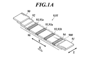
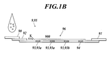
- FIG. 1A is a perspective view showing an example of an external configuration of a chromatographic test piece 9 (hereinafter referred to as a test piece 9), and FIG. 1B is a side view.
- the test piece 9 is used for detecting or quantifying the analyte in the sample in the chromatographic test.
- the test piece 9 is supplied with the sample and developed, and in the chromatography test apparatus 1 (see FIG. 2) described later. A scan for detecting the presence or absence of fluorescence is performed.
- the test piece 9 is formed in a rectangular plate shape that is long in the development direction K of the sample. As shown in FIG. 1B, the test piece 9 is in a case (not shown) that opens upward. And a test strip 95.
- test strip 95 is formed in a rectangular sheet shape that is long in the developing direction K, and a sample pad 90 is provided at one end of the upper surface, and an absorption pad 91 is provided at the other end.
- the sample pad 90 is a portion where a liquid sample is dropped and supplied. Further, the absorption pad 91 is a part that absorbs the sample dropped on the sample pad 90 and develops the sample in the deployment direction K by capillary action.
- a conjugate pad 92 is disposed on the downstream side in the development direction K with respect to the sample pad 90.
- the conjugate pad 92 includes a fluorescently labeled ligand that binds to the analyte contained in the sample. While moving the sample supplied from the sample pad 90 to the downstream side in the development direction K, the analyte in the sample. Is bound to a fluorescently labeled ligand. Details of the sample, the analyte, and the fluorescently labeled ligand will be described later.
- a membrane 96 extends from the lower surface of the conjugate pad 92 to the lower surface of the absorption pad 91, and the sample supplied from the conjugate pad 92 is transmitted and developed in the development direction K. Yes.
- the membrane 96 is made of a microporous inactive substance (a substance that does not react with an analyte, various ligands, various phosphors, etc.) that exhibits capillary action and develops the sample as soon as the sample is added.
- the membrane 96 a fibrous or non-woven fibrous matrix composed of polyurethane, polyester, polyethylene, polyvinyl chloride, polyvinylidene fluoride, nylon, nitrocellulose, cellulose derivatives such as cellulose acetate, or the like , Filter paper, glass fiber filter paper, cloth, cotton and the like.
- a membrane composed of a cellulose derivative or nylon, a filter paper, a glass fiber filter paper, etc. are preferably used, more preferably a nitrocellulose membrane, a mixed nitrocellulose ester (mixture of nitrocellulose and cellulose acetate) membrane, a nylon membrane, a filter paper. Is used.
- the scan area 900 is a rectangular area and is located on the inner side of both ends of the membrane 96 in the development direction K. Further, in FIG. 1 and FIGS. 3 and 4 described later, for the sake of convenience, the detection target region 93 and the marker 94 are shown so as to be visible, but may be provided so as not to be visible.
- the three detection target regions 93 are formed in a band shape and are spaced apart from each other in the development direction K by a predetermined interval, and are orthogonal to the development direction K, that is, the width direction of the test piece 9 (hereinafter referred to as detection). Extending in the line direction Z).
- the interval between the detection target areas 93 is constant at about 2 mm, and the length (width) of the detection target areas 93 in the development direction K is about 1 mm to 3 mm and equal to each other. .
- the two upstream detection target areas 93 are test lines 93a, and the most downstream detection target area 93 is a control line 93b.
- the test line 93a is an area also called a detection zone.
- a capture ligand that specifically captures the complex of the analyte and the fluorescently labeled ligand in the sample is immobilized on the test line 93a.
- one test line 93a captures a complex of an A-type influenza antigen as an analyte and a fluorescently labeled ligand
- the other test line 93a is an analyte.
- a complex of a type B influenza antigen as a light and a fluorescently labeled ligand is captured.
- control line 93b is an area also referred to as a reference zone.
- a capture ligand that specifically captures the fluorescently labeled ligand is immobilized on the control line 93b.
- test line 93a and control line 93b are formed on the membrane 96 by the same coating apparatus (for example, an ink jet printer). Further, as the capture ligands in the test line 93a and the control line 93b, conventionally known ligands can be used according to the type of analyte or fluorescent labeling ligand.
- the marker 94 is a region where fluorescence is generated, and in the present embodiment, the marker 94 is formed in a band shape and extends in a direction orthogonal to the development direction K, that is, the detection line direction Z.
- the marker 94 is disposed downstream of at least one detection target region 93 in the development direction K among the three detection target regions 93. In the present embodiment, the entire three detection target regions 93 are arranged. It is arrange
- the distance between the most downstream detection target region 93 and the marker 94 is equal to the interval between the detection target regions 93, and the length (width) of the marker 94 in the development direction K is the length of the detection target region 93. It is equal to (width).
- the marker 94 described above contains a phosphor, and preferably further contains a carrier carrying the phosphor.
- these phosphors and carriers those described later as phosphors and carriers (insoluble particles) in the fluorescently labeled ligand can be used.
- the wavelength region of the fluorescence generated from the marker 94 and the wavelength region of the fluorescence generated from the detection target region 93 overlap at least a part of wavelengths.
- at least one of the phosphor and the carrier contained in the marker 94 is cationic. Specifically, when the marker 94 does not contain a carrier, the phosphor is cationic, and when the marker 94 contains a carrier, the phosphor is cationic or the carrier is cationic.
- the phosphor of the marker 94 has an indocyanine skeleton represented by the following chemical structural formula, and emits fluorescence with excitation light in the range of 600 to 800 nm.
- examples of the cationic carrier include latex particles introduced with a primary amine.
- examples of such a carrier include “Polybead Amino Microspheres” (particle size 0.20 ⁇ m, manufactured by Polysciences, Inc., where “Polybead” is a registered trademark).
- cationic phosphors examples include BODIPY dyes, dyes having an indocyanine skeleton, coumarin dyes (such as AMCA), anilinonaphthalene sulfonic acid (ANS) dyes, Prodan dyes, Hoechst dyes, oranges. Yellow, YOYO dye (orange yellow dimer), thiazole orange, TOTO dye (thiazole orange dimer), and the like.
- phosphors having an indocyanine skeleton include, for example, Alexa Fluor 647 (where "Alexa Fluor” is a registered trademark), Cy5, Cy5.5, “S0830” (manufactured by DKSH Japan Ltd.) It is a cyanine dye.
- the above markers 94 are formed on the membrane 96 by the same coating apparatus as the test line 93a and the control line 93b.
- the sample is not particularly limited as long as it can contain proteins, saccharides, nucleic acids, various physiologically active substances and the like as analytes. Examples thereof include biological samples that can contain the target analyte, food extracts, and the like. Biological samples include whole blood, serum, plasma, urine, saliva, sputum, nasal or throat swab, cerebrospinal fluid, amniotic fluid, nipple discharge, tears, sweat, skin exudate, tissue, cells, and stool. And the like.
- the sample may be pretreated with an analyte in order to easily cause a specific binding reaction between the fluorescently labeled ligand or the capture ligand of the test line 93a and the analyte.
- pretreatment include chemical treatments using various chemicals such as acids, bases, surfactants, and physical treatments using heating, stirring, ultrasonic waves, etc. It may be used.
- the analyte is a substance that is not normally exposed on the surface, such as an influenza virus NP antigen
- a nonionic surfactant may be used in consideration of specific binding reaction, for example, binding reactivity between ligand and analyte such as antigen-antibody reaction. .
- the sample may be appropriately diluted with a solvent (water, physiological saline, buffer, or the like) used in a normal immunological analysis method or a water-miscible organic solvent.
- a solvent water, physiological saline, buffer, or the like
- Analytes include tumor markers, signaling substances, hormones and other proteins (including polypeptides, oligopeptides, etc.), nucleic acids (single or double stranded DNA, RNA, polynucleotides, oligonucleotides, PNA ( And other molecules such as lipids, test substances 93a, and other molecules such as lipids, and other molecules such as lipids (including oligosaccharides, polysaccharides, sugar chains, etc.) or sugar chains.
- CEA carcinoembryonic antigen
- HER2 protein HER2 protein
- PSA prostate specific antigen
- CA19-9 ⁇ -fetoprotein
- IPA immunity Inhibitory acidic protein
- CA15-3 CA125
- estrogen receptor progesterone Scepter
- IPA immunity Inhibitory acidic protein
- CA15-3 CA125
- estrogen receptor progesterone Scepter
- fecal occult blood troponin I, troponin T, CK-MB, CRP
- HCG human chorionic gonadotropin
- LH luteinizing hormone
- FSH follicle stimulating hormone
- syphilis antibody influenza virus, human hemoglobin, chlamydia antigen , Group A ⁇ -streptococcal antigen, HBs antibody, HBs antigen, rotavirus, adenovirus, albumin, glycated albumin and the like.
- the fluorescently labeled ligand is obtained by labeling a ligand that specifically binds to an analyte with fluorescent particles containing a phosphor.
- a ligand is a molecule or molecular fragment that recognizes an analyte contained in a sample or is recognized by the analyte and can specifically bind to the analyte.
- molecules or molecular fragments include nucleic acids (DNA, RNA, polynucleotides, oligonucleotides, PNA (peptide nucleic acids), etc., or nucleosides, nucleotides and their modified molecules, although they may be single-stranded.
- protein polypeptide, oligopeptide, etc.
- amino acid including modified amino acid
- carbohydrate oligo, etc., polysaccharide, substance containing sugar chain, etc.
- lipid or these The modified molecule, complex, etc. are mentioned.
- antibody includes a polyclonal antibody or a monoclonal antibody, an antibody obtained by genetic recombination, and an antibody fragment.
- the fluorescent particle means a particle in which a phosphor is directly or indirectly fixed to a carrier as an insoluble particle by chemical or physical bonding or adsorption.
- the fluorescently labeled ligand may be one in which fluorescent particles are directly bonded to the ligand, or one in which the ligand and fluorescent particles are bonded via a linker molecule, The ligand may be fixed to insoluble particles.
- the insoluble particles (carrier) constituting the fluorescent particles for example, synthetic polymer particles, inorganic compound particles, or polysaccharide particles are used.
- the synthetic polymer particles are not particularly limited, and examples thereof include latex particles and polylactic acid particles, and latex particles are preferable.
- the material of the latex particles is not particularly limited.
- the inorganic compound particles are not particularly limited, and examples thereof include metal particles such as gold, silver and platinum, or metal oxide particles such as metal colloid particles, porous glass particles, silica and alumina.
- the polysaccharide particles are not particularly limited, and examples thereof include agarose particles, dextran particles, cellulose particles, and chitosan particles.
- the phosphor contained in the fluorescent particles is not particularly limited.
- fluorescent particles when excited with light having a wavelength in the range of 200 to 700 nm (ultraviolet to near infrared light) as excitation light, Examples thereof exhibit fluorescence having a wavelength within the range of 400 to 900 nm (visible to near infrared light fluorescence).
- Specific phosphors include fluorescein dye molecules, rhodamine dye molecules, AlexaFluor (Invitrogen) dye molecules, BODIPY (Invitrogen) dye molecules, cascade dye molecules, coumarin dye molecules, and eosin dyes.
- Examples thereof include a dye molecule, an NBD dye molecule, a pyrene dye molecule, a Texas Red dye molecule, and a cyanine dye molecule. More specifically, 5-carboxy-fluorescein, 6-carboxy-fluorescein, 5,6-dicarboxy-fluorescein, 6-carboxy-2 ′, 4,4 ′, 5 ′, 7,7′-hexachlorofluorescein, 6-carboxy-2 ′, 4,7,7′-tetrachlorofluorescein, 6-carboxy-4 ′, 5′-dichloro-2 ′, 7′-dimethoxyfluorescein, naphthofluorescein, 5-carboxy-rhodamine, 6- Carboxy-rhodamine, 5,6-dicarboxy-rhodamine, rhodamine 6G, tetramethylrhodamine, X-rhodamine, and Alexa Fluor 350, Alexa Fluor405,
- phosphors that emit fluorescence with excitation light in the range of 600 to 800 nm have indocyanine skeletons such as Cy3.5, Alixa Fluor 647, Cy5, Cy5.5, AlexaFluor 680, Cy7, AlexaFluor 790.
- indocyanine skeletons such as Cy3.5, Alixa Fluor 647, Cy5, Cy5.5, AlexaFluor 680, Cy7, AlexaFluor 790.
- organic dyes such as acriflavine and DDAO
- cyanine derivatives such as brilliant blue and brilliant green
- fluorescent proteins such as allophycocyanin.
- the insoluble particles constituting the fluorescent particles are particles made of a polymer compound such as latex particles
- the phosphor is exposed to the surface of the particles or as long as it can be detected at the time of fluorescence detection. It may be kneaded so that it exists near the surface of the particle, or may be adsorbed on the surface of the particle.
- the method of immobilizing the ligand on fluorescent particles or insoluble particles can be roughly classified into a method of physically adsorbing the ligand to the fluorescent particles or insoluble particles and a method of covalent bonding as a chemical bond.
- the former includes, for example, a method in which the above-mentioned ligand is added to a solution in which silica particles or gold particles are colloidally dispersed as insoluble particles, and then left for a predetermined time for physical adsorption.
- the method has the advantage of simple operation.
- the latter includes, for example, a method in which a carboxyl group introduced on the particle surface of fluorescent particles or insoluble particles and an amino group of the above ligand are bonded by an amide bond using a condensing agent, or a fluorescent particle or There is a method of binding an insoluble particle and the ligand, and such a method has an advantage that the ligand can be introduced quantitatively and irreversibly into a fluorescent particle or an insoluble particle.
- a blocking agent such as bovine serum albumin solution is added to block the particle surface where the antibody is not bound. Is preferred.
- FIG. 2 is a perspective view showing an example of the external configuration of the chromatography test apparatus 1.
- the chromatography test apparatus 1 detects or quantifies an analyte on a test piece 9, and includes an insertion slot 10, a switch group 11, a display 12, and a printer unit 13. ing.
- the insertion port 10 is an opening for inserting the test piece 9 into the chromatography test apparatus 1 or discharging the test piece 9 in the chromatography test apparatus 1.
- the switch group 11 has a plurality of switches for giving various instructions to the chromatography test apparatus 1.
- the display 12 displays various types of information such as the analysis result of the test piece 9, and is an LCD (Liquid Crystal Display) in the present embodiment.
- the printer unit 13 prints out various information such as the analysis result of the test piece 9.
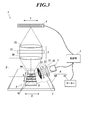
- FIG. 3 is a schematic diagram showing an example of the internal configuration of the chromatography test apparatus 1.
- the chromatography test apparatus 1 includes a light source 2, an irradiation optical system 3, a line sensor 4, a detection optical system 5, a scanning device 6, and a control unit 7.
- the light source 2 emits light and is a laser light source in the present embodiment.
- the wavelength of the laser light source is preferably in the range of 630 nm to 780 nm, although it depends on the type of fluorescently labeled ligand used.
- the irradiation optical system 3 is an optical system that guides the light emitted from the light source 2 to the test piece 9 and emits the irradiation light S with respect to the test piece 9.
- the lenses 30, 32, A band-pass filter 31 and an aperture 33 are included.
- the irradiation light S refers to a portion of the light irradiated from the light source 2 toward the test piece 9 until it hits the test piece 9 after passing through the irradiation optical system 3.
- the lens 30 converts the light emitted from the light source 2 into parallel light and makes it incident on the band-pass filter 31.
- the bandpass filter 31 passes only the frequency components that excite the fluorescently labeled ligand and the marker 94 of the test piece 9 to generate fluorescence among the frequency components of the light emitted from the light source 2.
- the lens 32 collects the light that has passed through the bandpass filter 31 on the test piece 9.
- the aperture 33 prevents the unnecessary light from hitting the test piece 9 by blocking the peripheral portion of the convergent light emitted from the lens 32.
- the line sensor 4 is a light receiving sensor that performs photoelectric conversion by a plurality of pixels arranged in a line, and is arranged extending in a predetermined longitudinal direction Y. As described above, by using the line sensor 4 as the light receiving sensor, it is possible to simplify the control of the signal processing and the configuration of the scanning mechanism as compared with the case where the area sensor or the photodiode is used as the light receiving sensor.
- a conventionally known sensor such as a line CCD, a line CMOS, or a one-dimensional photodiode can be used.
- the detection optical system 5 is an optical system that guides the detection target light T generated in the test piece 9 due to the irradiation light S to the line sensor 4.
- the lenses 50 and 52 and the bandpass filter 51 are used. And have.
- the detection target light T is a portion of the light generated by the test piece 9 due to the light emitted from the light source 2 until it enters the detection optical system 5 and is excited. It includes fluorescence generated by the fluorescently labeled ligand and the marker 94, reflected light from the test piece 9, and scattered light.
- the lens 50 is configured to convert the detection target light T generated in the test piece 9 into parallel light and enter the bandpass filter 51.
- the band-pass filter 51 is configured to pass only the frequency components of the fluorescence generated by the fluorescently labeled ligand and the marker 94 among the frequency components of the detection target light T.
- the lens 52 condenses the light that has passed through the bandpass filter 51 on the line sensor 4.
- the scanning device 6 scans at least one optical element in the irradiation optical system 3 or the detection optical system 5 or the test piece 9 in the scanning direction X as a scanning object, so that the irradiation spot of the irradiation light S is irradiated on the test piece 9.
- a plate-like support base 60 that supports the test piece 9 from below and a motor 61 that reciprocates the support base 60 in the scanning direction X are used.
- the test piece 9 is scanned in the scanning direction X together with the support base 60 as a scanning object.
- the motor 61 a conventionally known motor such as a stepping motor, a voice coil motor, or a DC motor can be used.
- the scanning direction X is parallel to the developing direction K, and is orthogonal to the longitudinal direction Y of the line sensor 4.
- the control unit 7 executes predetermined processing according to an instruction input from the switch group 11, performs an instruction to each functional unit, data transfer, and the like, and comprehensively controls the chromatography test apparatus 1, Various operations are performed.
- the control unit 7 detects or quantifies the analyte based on the output signal from the line sensor 4.
- 3 illustrates a state in which the control unit 7 is connected to the light source 2, the line sensor 4, the motor 61, and the like, but the connection target of the control unit 7 is not limited to these.
- the test piece 9 is inserted into the insertion port of the chromatography test apparatus 1. 10 is inserted.
- the time from when the sample is dropped to when the fluorescently labeled ligand is bound to the control line 93b is generally about 10 minutes after the sample is dropped.
- the control unit 7 performs a scanning process (hereinafter referred to as a preliminary scanning process) for detecting the position and width of the marker 94 on the test piece 9. Specifically, in this preliminary scanning process, first, the control unit 7 drives the motor 61 to move the test piece 9 by one step in the scanning direction X, thereby irradiating the irradiation spot on the test piece 9 with the irradiation light S. Is moved from the downstream end to the upstream end side in the scan area 900.
- a predetermined amount smaller than the width of the marker 94 in the scanning direction X is set in advance.
- control unit 7 After the control unit 7 turns on the light source 2 to irradiate the light, it acquires light reception signal data at each pixel from the line sensor 4 and turns off the light source 2. Then, the control unit 7 repeats the above process until the entire area of the marker 94 is detected in the scanning direction X, and then ends the preliminary scanning process.
- the control unit 7 calculates and specifies the positions of the test line 93a and the control line 93b based on the position of the marker 94 detected by the preliminary scanning process, and also controls the control line. Based on the amount of light at 93b, the power of the light source 2 is changed, the threshold used for detection of the test line 93a is changed, and then scanning processing for detecting the presence or amount of the analyte in the test line 93a, that is, main scanning. Process. As this main scanning process, a conventionally known process can be used.
- the control unit 7 changes the power of the light source 2 with reference to the light amount at the marker 94 instead of using the light amount at the control line 93b as a reference, and changes the threshold used for detection of the test line 93a. Also good.
- the reference light amount is not affected by the intensity of the capture reaction of the labeled ligand.
- the housing case and the membrane 96 are separated from each other. It is possible to prevent the position specifying accuracy of the test line 93a from being affected by the alignment accuracy. Further, since the marker 94 generates fluorescence, the position of the test line 93a is determined by the strength of the capture reaction, unlike the conventional case where the capture region of the fluorescently labeled ligand that flows along with the sample, that is, the position of the control line is the reference position. It is possible to prevent the accuracy from being affected. Accordingly, the position of each detection target region 93 can be accurately specified.
- the marker 94 since the marker 94 generates fluorescence, the position of the marker 94 can be detected using equipment for detecting fluorescence from the detection target region 93. Therefore, since it is not necessary to provide new equipment for detecting and quantifying the position of the marker 94, it is possible to prevent the test cost from increasing. In addition, since the marker 94 is cationic, it is less likely to be water-soluble in the sample as compared with the case of being anionic.
- the component of the marker 94 can be prevented from flowing due to the development of the sample, the exact position of the marker 94 cannot be specified, and the position of the test line cannot be specified accurately, or the void in the membrane 96 Is blocked by the component of the marker 94 and the development of the sample due to capillarity is inhibited, the complexation reaction between the analyte in the sample and the fluorescently labeled ligand, and the complex capture reaction in the test line 93a is inhibited. It is possible to prevent the light detection accuracy and quantitative accuracy from being lowered.
- the marker for detecting the fluorescence from the detection target region 93 is used.
- the position 94 can be reliably detected. Therefore, it is possible to reliably prevent the cost of the test from being increased by providing new equipment for detecting and quantifying the position of the marker 94.
- the marker 94 is disposed downstream of the at least one detection target region 93 in the development direction K, the analyte in the sample and the fluorescently labeled ligand that flows along with the sample are located at the position of the marker 94. Even when the dam is blocked, data relating to detection and quantification of the analyte can be obtained in at least one detection target region 93.
- the marker 94 is disposed on the downstream side in the development direction K from the whole of the plurality of detection target regions 93, the analyte in the sample and the fluorescently labeled ligand that flows along with the sample are the markers 94. Even in the case of being dammed up at the position, data relating to detection and quantification of the analyte can be obtained in all the detection target regions 93.
- the position specifying accuracy of the test line 93a is affected by the alignment accuracy of each member. Can be prevented.
- the marker 94 contains a phosphor carrier, it is possible to reliably prevent the components of the marker 94 from flowing due to the development of the sample. Therefore, the exact position of the marker 94 cannot be specified, and the position of the test line 93a cannot be specified accurately, or the complexing reaction between the analyte in the sample and the fluorescently labeled ligand, or the capture reaction of the complex in the test line. It is possible to reliably prevent the detection accuracy and quantitative accuracy of the analyte from being impaired.
- the phosphor since the phosphor is supported on the carrier, the phosphor is not easily dissolved in water due to the cationic nature, and even if it is difficult to uniformly coat the membrane 96, the phosphor and the carrier
- the composite can be uniformly dispersed in a solvent and applied uniformly on the membrane 96.
- the reference light amount is different from the case where the light amount at the control line 93b is used as the reference light amount. Is not affected by the intensity of the capture reaction of the fluorescently labeled ligand, so that the analyte can be detected and quantified accurately.
- the operation check and calibration of the chromatography test apparatus 1 are performed using this amount of light. Can do.
- the test piece 9A in the present modification includes a test strip 95A and a transparent cover member 901 disposed on the test strip 95A as shown in FIG. ing.
- the cover member 901 does not necessarily have to be transparent as long as fluorescence generated in the test strip 95A can be detected from above the cover member 901.
- the test strip 95A has a membrane 96A.
- the membrane 96A has the same configuration as the membrane 96 in the above embodiment except that the marker 94 is not provided.
- the cover member 901 is a member that covers the upper surface of the test strip 95A, and preferably covers the region from the upper surface of the conjugate pad 92 to the most downstream detection target region 93 of the upper surface of the membrane 96A. ing. It is preferable that there is a space between the cover member 901 and the upper surface of the membrane 96A so that a sample containing an analyte can be developed on the membrane 96A, and if necessary, the lower surface of the cover member 901 and / or the membrane 96A. A spacer or the like may be formed on the upper surface. However, the cover member 901 may cover the upper surface of the membrane 96A with an adhesive. For example, in the hydrophilic film, the pressure-sensitive adhesive layer may be formed on the entire surface or the peripheral edge of the surface facing the membrane 96A.
- a liquid impermeable sheet made of PET or the like may be used, or a hydrophilic film may be used.
- the hydrophilic film refers to a film in which at least the both surfaces of the film are in contact with the membrane 96A (lower side), and the “hydrophilic” refers to a water contact angle in the air. It means having a surface of 50 ° or less, preferably 40 ° or less, more preferably 30 ° or less.
- the “water contact angle” is a static contact angle formed between water in the air and the film surface, and more specifically, an angle formed between water and the film surface generated when water is dropped on the film. is there. In other words, the “water contact angle” is an angle formed between the gas-liquid interface of the water droplet and the film surface at the point where the gas-liquid interface of the water droplet contacts the film surface.
- This water contact angle can be evaluated by measuring the water contact angle in air by various conventionally known methods such as the ⁇ / 2 method. More specifically, the water contact angle is determined by dropping 2 ⁇ l of pure water in an atmosphere of 23 ° C. and 50% RH and using a contact angle meter (Kyowa Interface Chemical Co., Ltd., model: CA-X150). , ⁇ / 2 method.
- the hydrophilic film is not particularly limited as long as it has a hydrophilic surface as described above.
- the hydrophilic film may be, for example, a film made of a hydrophilic polymer such as cellophane. Further, it may be a film obtained by adding a modifier to a hydrophobic polymer and obtained from a polymer or a composition imparted with hydrophilicity, or at least a membrane 96A of a film made of a hydrophobic polymer. It may be a film obtained by surface-treating the surface on the side in contact with the surface to impart hydrophilicity.
- the hydrophobic polymer has a water contact angle of more than 50 ° on the surface, for example, polyester resins such as polyethylene terephthalate and polyethylene naphthalate, polyolefin resins such as polyethylene, polypropylene, polyisobutylene and polybutadiene, polycarbonate
- polyester resins such as polyethylene terephthalate and polyethylene naphthalate
- polyolefin resins such as polyethylene, polypropylene, polyisobutylene and polybutadiene
- polycarbonate examples include polymethyl methacrylate resin, polyvinyl chloride resin, cellulose ester resin, polyimide resin, polyamide resin, polysulfone resin, AS resin, ABS resin, melamine resin, polyvinyl acetate, and polyvinyl fluoride.
- polyvinyl alcohol polyvinyl pyrrolidone
- modified polyvinyl alcohol a copolymer with acrylamide, unsaturated carboxylic acid, sulfonic acid monomer, cationic monomer, unsaturated silane monomer, unsaturated ethylene oxide monomer, etc.
- Modified polyvinylpyrrolidone copolymer with vinyl acetate, unsaturated imidazole, vinyl caprolactone, etc.
- hydrophilic acrylic polymer polyacrylic acid, polyacrylates, polyacrylamide, polyisopropylacrylamide, polyformamide, polyethylene glycol, Starch, modified starch, gelatin, casein, algin, cellulose compounds (carboxymethylcellulose, methylcellulose, ethylcellulose, hydroxyethylcellulose), hydrophilic Hydrophilic polymers such as tan polymers, cellulose compounds, water-soluble nylon, polyvinyl formal, polyvinyl acetal, polyvinyl benz
- the modifier is a hydrophilic polymer or polysaccharide
- a crosslinking agent such as a carbodiimide compound, a polyisocyanate compound, an oxazoline compound, or an epoxy compound is added to the hydrophobic polymer together with the modifier to make the polymer hydrophobic.
- the polymer and the modifier may be cross-linked.
- inorganic oxide particles may be added to the hydrophobic polymer as the inorganic oxide, or an inorganic oxide in which the inorganic oxide is dispersed in water.
- a sol may be added.
- the inorganic oxide as the modifier may have a photocatalytic action such as amorphous titania or hydrous titania.
- Surface treatment of hydrophobic film includes irradiation with radiation, ultraviolet rays, arc, direct current glow, high frequency, micro-electrochemical treatment such as plasma treatment by corona discharge, etc., coupling with hydrophilic groups such as hydroxyl groups and carboxyl groups Chemical surface treatment with an agent or the like can be mentioned.
- a coupling agent a silane coupling agent, a titanium coupling agent, etc. are mentioned.
- the color tone and transparency of the cover member 901 are preferably such that the absorption and scattering of irradiation light and excitation light do not substantially affect the measurement of fluorescence intensity.
- a hydrophilic transparent film is used as such a cover member 901
- specific examples thereof include a TAC film having a high light transmittance, and a polyolefin film such as polycarbonate and polypropylene.
- the sample can be rapidly developed as compared with the case of using the liquid impermeable sheet, and the sample development time is short.
- the analyte can be detected or quantified with good sensitivity.
- a marker 94A is provided on the upper surface of the cover member 901 described above.
- the marker 94 ⁇ / b> A is a region that includes a cationic material and generates fluorescence, like the marker 94 in the above embodiment, and extends in the detection line direction Z. Unlike the marker 94 in the above-described embodiment, the marker 94A does not contact the sample developed on the membrane 96A. It is possible.
- the detection target region 93 is provided in the membrane 96, and the marker 94 is the cover member 901. Therefore, it is possible to reliably prevent the component of the marker 94 from flowing due to the development of the sample. Accordingly, the exact position of the marker 94 cannot be specified, and the position of the test line 93a cannot be specified correctly, or the void in the membrane 96 is blocked with the components of the marker 94, and the sample development due to capillary action is inhibited. To prevent degradation of analyte detection accuracy and quantification accuracy due to inhibition of the complexation reaction between the analyte in the sample and the fluorescently labeled ligand and the complex capture reaction in the test line 93a. Can do.
- the detection target areas 93 are described as three, but may be two, four or more. Also, two of the three detection target areas 93 have been described as the test lines 93a and one as the control lines 93b, but all three may be the test lines 93a.
- test strip 95 has been described as a long rectangular shape, other arbitrary shapes such as an L shape may be used. In this case, the sample is developed along the shape of the test strip 95 from the addition position.
- the sample is added to one end of the test strip 95, it may be added to the central portion.
- the sample is developed on the test strip 95 from the addition position toward the end (periphery).
- the detection target region 93 and the marker 94 have been described as shapes extending in a direction orthogonal to the development direction K, at least one of the extending directions may be the other direction, or a shape that does not extend in one direction, for example, It is good also as a circle.
- one marker 94 is provided on the test strip 95, a plurality of markers 94 may be provided.
- the same number of markers 94 as the detection target area 93 may be disposed in the vicinity of the detection target area 93.
- the marker 94A is described as being provided on the upper surface of the cover member 901. However, as long as the marker 94A is not swept away by the sample developed on the membrane 96A, the marker 94A is disposed on the lower surface of the cover member 901. It may be provided.
- insoluble carrier dispersion carrying cationic phosphor As a cationic phosphor contained in the marker 94, 2- [5- [1,1-Dimethyl-3- (3-methyl-butyl) -1,3-dihydro-benzo [e] indol-2-ylidene] -penta-1,3-dienyl] -1,1-dimethyl-3- (3-methyl-butyl) -1H-benzo [e] indolium hexafluorophosphate (product number “S0830”, manufactured by DKSH Japan Ltd.) .
- This phosphor has an indocyanine skeleton.
- polystyrene latex particles having a particle size of 220 nm (product number “IMMUTEX P2219” (where “IMMUTEX” is a registered trademark), manufactured by JSR Corporation) were used as a water-insoluble carrier carrying a phosphor.
- polystyrene latex particles “P2219” were suspended in 400 ⁇ L of DMSO (dimethyl sulfoxide) and heated to 120 ° C.
- DMSO dimethyl sulfoxide
- 20 ⁇ L of a DMSO solution of a cationic phosphor “S0830” (the phosphor concentration was 100 mg / mL) was added and heated at 120 ° C. for 1 hour.
- 5 mL of a water / ethanol mixed solvent is added to this suspension to suspend it, and the particles are collected by centrifugation (15000 ⁇ G, 30 min).
- an aqueous solution of 0.5 wt% Triton-X100 (surfactant) is used.
- the particles were washed to prepare a dispersion of latex particles carrying a cationic phosphor (however, the concentration of latex particles was 0.1 wt%).
- test line 93a As the detection target region 93, 11.7 mm from the downstream end in the scan region 900 out of the upper surface of the membrane 96 made of trinitrocellulose (Millipore, white, width 60 mm ⁇ length 350 mm), Separate capture ligands were applied at 14.7 mm and 17.7 mm positions, respectively.
- the test line 93a formed at the most upstream position is the test line 93a 1
- the test line 93a formed at the second most upstream position is the test line 93a 2
- the test is formed at the most downstream position.
- the capture ligand of the test line 93a 1 is defined as capture ligand (1)
- the analyte captured by the capture ligand (1) is defined as analyte (1)
- the capture ligand of the test line 93a 2 is the capture ligand (2)
- the analyte captured by the capture ligand (2) is the analyte (2)
- the capture ligand of the test line 93a 3 is the capture ligand (3
- the analyte captured by the capture ligand (3) is defined as analyte (3).
- the latex particle dispersion adjusted as described above was applied to a position 20.7 mm from the downstream end in the scan region 900.
- a positive pressure spray device “BioJet” manufactured by BioDot was used for coating.
- a test strip (hereinafter referred to as a test strip of the example) 95 was manufactured using this membrane 96.
- a test strip (hereinafter, referred to as a test strip of the comparative example) 95H in which the marker 94 is not formed was manufactured.
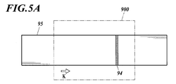
- the test line 93a is shown so as not to be visible, and in FIG. 5A, the marker 94 is shown so as to be visible.
- the present invention is suitable for a chromatographic test piece, a chromatographic test method, and a membrane that need to specify the position of the detection target region accurately.
Landscapes
- Health & Medical Sciences (AREA)
- Immunology (AREA)
- Life Sciences & Earth Sciences (AREA)
- Chemical & Material Sciences (AREA)
- Engineering & Computer Science (AREA)
- Pathology (AREA)
- General Physics & Mathematics (AREA)
- General Health & Medical Sciences (AREA)
- Biochemistry (AREA)
- Analytical Chemistry (AREA)
- Physics & Mathematics (AREA)
- Urology & Nephrology (AREA)
- Molecular Biology (AREA)
- Hematology (AREA)
- Biomedical Technology (AREA)
- Food Science & Technology (AREA)
- Medicinal Chemistry (AREA)
- Microbiology (AREA)
- Cell Biology (AREA)
- Biotechnology (AREA)
- Nuclear Medicine, Radiotherapy & Molecular Imaging (AREA)
- Investigating, Analyzing Materials By Fluorescence Or Luminescence (AREA)
Abstract
蛍光標識リガンドを用いたクロマトグラフィー試験で試料内のアナライトを検出または定量するために使用され、試料を供給されて所定の展開方向Kに展開させるとともに、蛍光の有無を検知するためのスキャンが行われるクロマトグラフィー試験片9は、スキャンの行われるスキャン領域900内に、展開方向Kに離間した状態で配設された、アナライトの有無または量を検知するための複数の検知対象領域93と、カチオン性の材料を含んで蛍光を生じるマーカー94と、を備える。
Description
本発明は、クロマトグラフィー試験片、クロマトグラフィー試験方法及びメンブレンに関するものである。
従来、アナライトを検出または定量するクロマトグラフィー試験においては、試料を供給されて所定の展開方向に展開させるクロマトグラフィー試験片が用いられている。このクロマトグラフィー試験片には、上方に開口したハウジングケースと、当該ハウジングケース内に収容されるとともに、試料を伝わらせて所定の展開方向に展開させるメンブレンとが具備されている。このメンブレンには、アナライトの有無または量を検知するための複数の検知対象領域として、テストライン及びコントロールラインが間隔をおいて短冊状に設けられている。このうち、テストラインとは、試料中のアナライト(例えば抗原)と、標識リガンド(例えば抗体)との複合体を特異的に捕捉する捕捉リガンド(抗原特異的抗体)が固定化されたラインであり、コントロールラインとは、標識リガンドを特異的に捕捉する捕捉リガンド(標識抗体特異的抗体)が固定化されたラインである。
このようなクロマトグラフィー試験片においては、一端に液状の試料が滴下されると、標識リガンドとアナライトとの結合が促された後、毛細管現象により複合体と標識リガンドがクロマトグラフィー試験片内を他端に向かって移動する結果、テストライン及びコントロールラインでそれぞれ複合体(アナライトと標識リガンドとの複合体)または標識リガンドが捕捉されるので、両ラインの呈色を光学的に検出することによって、アナライトが定性的あるいは定量的に検出される。
ところで、クロマトグラフィー試験を行う際、テストラインの位置が分からないと、試験結果を出すのに時間が掛かってしまうという問題がある。具体的には、テストラインが呈色していない場合には、テストラインの位置が分からないと、テストライン以外の領域でも呈色が無いことを確認するために時間が掛かってしまう。また、テストラインが呈色している場合には、テストラインが複数存在すると、何れのテストラインが呈色しているのかをデータ解析や画像解析により確認するために時間が掛かってしまう。
そのため、近年、テストラインの位置を特定するための2つの技術が提案されている。
1つ目の技術は、検知対象領域から生じる蛍光の検出によってアナライトの検出または定量を行うクロマトグラフィー試験の技術分野において提案されており、アナライトの有無や量に係らずコントロールラインから蛍光が生じることを利用し、蛍光検出によってコントロールラインの位置を検出した後、この位置を基準位置としてテストラインの位置を特定するようになっている(例えば特許文献1参照)。
1つ目の技術は、検知対象領域から生じる蛍光の検出によってアナライトの検出または定量を行うクロマトグラフィー試験の技術分野において提案されており、アナライトの有無や量に係らずコントロールラインから蛍光が生じることを利用し、蛍光検出によってコントロールラインの位置を検出した後、この位置を基準位置としてテストラインの位置を特定するようになっている(例えば特許文献1参照)。
また、2つ目の技術は、メンブレンを格納するハウジングケースに位置特定用のマーカーを予め設けておき、このマーカーの位置を基準位置としてテストラインの位置を特定するようになっている。
しかしながら、上記1つ目の技術では、コントロールラインにおける標識リガンドの捕捉反応が弱い場合に、コントロールラインの位置、つまり基準位置が正確に特定されず、その結果、テストラインの位置が正確に特定されなくなってしまう。
また、上記2つ目の技術では、ハウジングケースとメンブレンとの位置合わせの精度が低い場合に、マーカーの位置(基準位置)とテストラインとの位置関係が変化してしまい、テストラインの位置が正確に特定されなくなってしまう。また、マーカーの検出手法と検知対象領域での呈色の検出手法とが異なる場合、例えば、マーカーから生じる蛍光で当該マーカーを検出しつつ、検知対象領域の呈色を目視で検出する場合や、目視でマーカーを検出しつつ、検知対象領域から生じる蛍光で当該検知対象領域の呈色を検出する場合には、マーカーの検出と、検知対象領域の呈色の検出とを別々の作業・設備で行わなければならず、試験のコストが高くなってしまう。
一方、これらの問題を考慮すると、コントロールラインとは別に位置特定用のマーカーをメンブレンに設けることも考えられるが、単純にメンブレンにマーカーを設けると、試料の展開によってマーカー成分が流れてしまう。そして、この場合には、マーカーの正確な位置が特定できずにテストラインの位置が正確に特定されなくなったり、メンブレン内の空隙がマーカー成分で塞がれて毛細管現象による試料の展開が阻害されたり、試料中のアナライトと標識リガンドとの複合化反応やテストラインにおける複合体の捕捉反応が阻害されてアナライトの検出精度が低下したりすることとなる。
そこで、本発明は以上のような事情に鑑みてなされたものであり、アナライトの検出精度を低下させることなく、各検知対象領域の位置を正確に特定することのできるクロマトグラフィー試験片、クロマトグラフィー試験方法及びメンブレンを提供することを目的とするものである。
上記課題を解決するため、本発明の一側面を反映したクロマトグラフィー試験片は、
蛍光標識リガンドを用いたクロマトグラフィー試験で試料内のアナライトを検出または定量するために使用され、試料を供給されて所定の展開方向に展開させるとともに、蛍光の有無を検知するためのスキャンが行われるクロマトグラフィー試験片において、
スキャンの行われるスキャン領域内に、
前記展開方向に離間した状態で配設された、アナライトの有無または量を検知するための複数の検知対象領域と、
カチオン性の材料を含んで蛍光を生じるマーカーと、
を備える。
蛍光標識リガンドを用いたクロマトグラフィー試験で試料内のアナライトを検出または定量するために使用され、試料を供給されて所定の展開方向に展開させるとともに、蛍光の有無を検知するためのスキャンが行われるクロマトグラフィー試験片において、
スキャンの行われるスキャン領域内に、
前記展開方向に離間した状態で配設された、アナライトの有無または量を検知するための複数の検知対象領域と、
カチオン性の材料を含んで蛍光を生じるマーカーと、
を備える。
また、本発明の一側面を反映したクロマトグラフィー試験方法は、
本発明のクロマトグラフィー試験片を用いて試料内のアナライトを検出または定量する。
本発明のクロマトグラフィー試験片を用いて試料内のアナライトを検出または定量する。
また、本発明の一側面を反映したメンブレンは、
蛍光標識リガンドを用いたクロマトグラフィー試験で試料内のアナライトを検出または定量するために使用され、試料を供給されて所定の展開方向に展開させるとともに、蛍光の有無を検知するためのスキャンが行われるクロマトグラフィー試験片に備えられるメンブレンにおいて、
当該メンブレンは、
供給される試料を伝わらせて前記展開方向に展開させるものであり、
スキャンの行われるスキャン領域内に、
前記展開方向に離間した状態で配設された、アナライトの有無または量を検知するための複数の検知対象領域と、
カチオン性の材料を含んで蛍光を生じるマーカーと、
が設けられている。
蛍光標識リガンドを用いたクロマトグラフィー試験で試料内のアナライトを検出または定量するために使用され、試料を供給されて所定の展開方向に展開させるとともに、蛍光の有無を検知するためのスキャンが行われるクロマトグラフィー試験片に備えられるメンブレンにおいて、
当該メンブレンは、
供給される試料を伝わらせて前記展開方向に展開させるものであり、
スキャンの行われるスキャン領域内に、
前記展開方向に離間した状態で配設された、アナライトの有無または量を検知するための複数の検知対象領域と、
カチオン性の材料を含んで蛍光を生じるマーカーと、
が設けられている。
本発明によれば、アナライトの検出精度を低下させることなく、各検知対象領域の位置を正確に特定することができる。
以下、本発明を図示の実施の形態に基づいて説明するが、本発明は該実施の形態に限られない。なお、図中、同一あるいは同等の部分には同一の番号を付与し、重複する説明は省略する。
(1.クロマトグラフィー試験片)
始めに、本発明に係るクロマトグラフィー試験片について、図1を用いて説明する。ここで、図1Aはクロマトグラフィー試験片9(以下、試験片9とする)の外観構成の一例を示す斜視図であり、図1Bは側面図である。
始めに、本発明に係るクロマトグラフィー試験片について、図1を用いて説明する。ここで、図1Aはクロマトグラフィー試験片9(以下、試験片9とする)の外観構成の一例を示す斜視図であり、図1Bは側面図である。
試験片9は、クロマトグラフィー試験で試料内のアナライトを検出または定量するために使用されるものであり、試料を供給されて展開させるとともに、後述のクロマトグラフィー試験装置1(図2参照)において、蛍光の有無を検知するためのスキャンが行われるようになっている。
この試験片9は、図1Aに示すように、試料の展開方向Kに長尺な矩形板状に形成されており、図1Bに示すように、上方に開口したケース(図示せず)内に、テストストリップ95を有している。
(1-1.テストストリップ)
テストストリップ95は、展開方向Kに長尺な矩形シート状に形成されており、上面における一端部にはサンプルパッド90が設けられ、他端部には吸収パッド91が設けられている。
テストストリップ95は、展開方向Kに長尺な矩形シート状に形成されており、上面における一端部にはサンプルパッド90が設けられ、他端部には吸収パッド91が設けられている。
このうち、サンプルパッド90は、液状の試料が滴下されて供給される部分である。また、吸収パッド91は、サンプルパッド90に滴下された試料を吸収することにより、当該試料を毛細管現象によって展開方向Kに展開させる部分である。
サンプルパッド90に対して展開方向Kの下流側には、コンジュゲートパッド92が配設されている。このコンジュゲートパッド92は、試料中に含まれるアナライトと結合する蛍光標識リガンドを含んでおり、サンプルパッド90から供給される試料を展開方向Kの下流側に移動させつつ、試料内のアナライトを蛍光標識リガンドと結合させるようになっている。なお、試料やアナライト、蛍光標識リガンドの詳細は後述する。
コンジュゲートパッド92の下面から吸収パッド91の下面までの間には、メンブレン96が延在しており、コンジュゲートパッド92から供給される試料を伝わらせて展開方向Kに展開させるようになっている。メンブレン96は、毛管現象を示し、試料を添加すると同時に当該試料が展開するような微細多孔性の不活性物質(アナライト、各種リガンド、各種蛍光体などと反応しない物質)で形成されている。具体的には、メンブレン96としては、ポリウレタン、ポリエステル、ポリエチレン、ポリ塩化ビニル、ポリフッ化ビニリデン、ナイロン、ニトロセルロース又は酢酸セルロース等のセルロース誘導体等で構成される繊維状又は不織繊維状マトリクス、膜、濾紙、ガラス繊維濾紙、布、綿等が挙げられる。中でも、好ましくはセルロース誘導体やナイロンで構成される膜、濾紙、ガラス繊維濾紙等が用いられ、より好ましくはニトロセルロース膜、混合ニトロセルロースエステル(ニトロセルロースと酢酸セルロースの混合物)膜、ナイロン膜、濾紙が用いられる。
このメンブレン96の上面のうち、後述のクロマトグラフィー試験装置1によってスキャンの行われるスキャン領域900内には、アナライトの有無または量を検知するための3つの検知対象領域93と、検知対象領域93の位置を特定するためのマーカー94とが設けられている。なお、本実施の形態においては、スキャン領域900は矩形状の領域となっており、展開方向Kにおけるメンブレン96の両端よりも内側に位置している。また、図1や、後述の図3,図4においては、便宜上、検知対象領域93やマーカー94を視認できるように図示しているが、視認できないように設けられてもよい。
3つの検知対象領域93は、帯状に形成されており、展開方向Kに所定の間隔を空けて離間して配設され、展開方向Kの直交方向、つまり試験片9の幅方向(以下、検知ライン方向Zとする)にそれぞれ延在している。なお、本実施の形態においては、検知対象領域93の間隔は2mm程度で一定となっており、展開方向Kにおける検知対象領域93の長さ(幅)は1mm~3mm程度で互いに等しくなっている。
これら3つの検知対象領域93のうち、上流側の2つの検知対象領域93はテストライン93aとなっており、最も下流側の検知対象領域93はコントロールライン93bとなっている。
テストライン93aは、検出ゾーンとも称される領域である。このテストライン93aには、試料中のアナライトと蛍光標識リガンドとの複合体を特異的に捕捉する捕捉リガンドが固定化されている。なお、本実施の形態においては2つのテストライン93aのうち、一方のテストライン93aはアナライトとしてのA型のインフルエンザ抗原と蛍光標識リガンドとの複合体を捕捉し、他方のテストライン93aはアナライトとしてのB型のインフルエンザ抗原と蛍光標識リガンドとの複合体を捕捉するようになっている。
また、コントロールライン93bは、参照ゾーンとも称される領域である。このコントロールライン93bには、蛍光標識リガンドを特異的に捕捉する捕捉リガンドが固定化されている。
なお、以上のテストライン93a及びコントロールライン93bは、同一の塗布装置(例えばインクジェットプリンタなど)によってメンブレン96上に形成されている。また、テストライン93a及びコントロールライン93bにおける捕捉リガンドとしては、アナライトや蛍光標識リガンドの種類に応じて、従来より公知のものを用いることができる。
マーカー94は、蛍光を生じる領域であり、本実施の形態においては、帯状に形成されて、展開方向Kの直交方向、つまり検知ライン方向Zに延在している。このマーカー94は、3つの検知対象領域93のうち少なくとも1つの検知対象領域93よりも展開方向Kの下流側に配設されており、本実施の形態においては、3つの検知対象領域93の全体よりも展開方向Kの下流側に配設されている。なお、最も下流側の検知対象領域93とマーカー94との間隔は検知対象領域93同士の間隔と等しくなっており、展開方向Kにおけるマーカー94の長さ(幅)は検知対象領域93の長さ(幅)と等しくなっている。
以上のマーカー94は、蛍光体を含有しており、好ましくは、蛍光体を担持する担体を更に含有している。
これら蛍光体,担体としては、蛍光標識リガンドにおける蛍光体,担体(不溶性粒子)として後述されるもの等を用いることができる。但し、マーカー94から生じる蛍光の波長領域と、検知対象領域93から生じる蛍光の波長領域とは、少なくとも1部の波長が重複するようになっている。また、本発明においては、マーカー94に含まれる蛍光体及び担体のうち、少なくとも一方はカチオン性となっている。具体的には、マーカー94に担体が含まれない場合には、蛍光体がカチオン性であり、マーカー94に担体が含まれる場合には、蛍光体がカチオン性であるか、担体がカチオン性であるか、或いは蛍光体及び担体の両方がカチオン性である。また、好ましくは、マーカー94の蛍光体は、下記の化学構造式で示されるインドシアニン骨格を有し、600~800nmの範囲内の励起光で蛍光発光する。
これら蛍光体,担体としては、蛍光標識リガンドにおける蛍光体,担体(不溶性粒子)として後述されるもの等を用いることができる。但し、マーカー94から生じる蛍光の波長領域と、検知対象領域93から生じる蛍光の波長領域とは、少なくとも1部の波長が重複するようになっている。また、本発明においては、マーカー94に含まれる蛍光体及び担体のうち、少なくとも一方はカチオン性となっている。具体的には、マーカー94に担体が含まれない場合には、蛍光体がカチオン性であり、マーカー94に担体が含まれる場合には、蛍光体がカチオン性であるか、担体がカチオン性であるか、或いは蛍光体及び担体の両方がカチオン性である。また、好ましくは、マーカー94の蛍光体は、下記の化学構造式で示されるインドシアニン骨格を有し、600~800nmの範囲内の励起光で蛍光発光する。
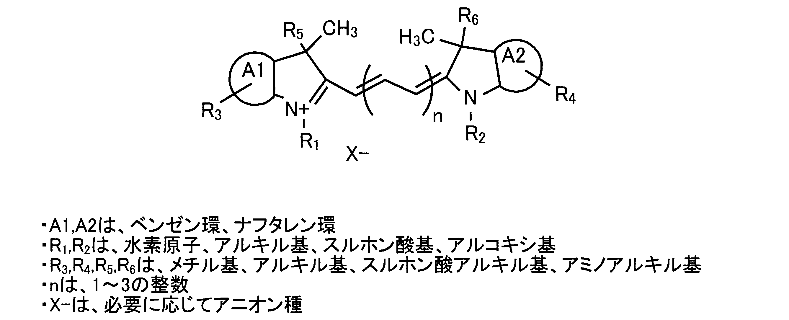
ここで、カチオン性の担体としては、1級アミン導入のラテックス粒子などが挙げられる。このような担体としては、例えば「Polybead Amino Microspheres」(粒径0.20μm, Polysciences社製。但し「Polybead」は登録商標)などが挙げられる。
また、カチオン性の蛍光体としては、BODIPY系色素や、インドシアニン骨格を有する色素、クマリン色素(Aminomethyl coumarin:例えばAMCA等)、アニリノナフタレンスルホン酸(ANS)色素、Prodan色素、Hoechst色素、オレンジイエロー、YOYO色素(オレンジイエローの2量体)、チアゾールオレンジ、TOTO色素(チアゾールオレンジの2量体)等が挙げられる。
また、インドシアニン骨格を有する蛍光体(インドレニン系)とは、例えばAlexa Fluor 647(但し「Alexa Fluor」は登録商標),Cy5, Cy5.5, 「S0830」(DKSHジャパン株式会社製)などのシアニン系色素である。
以上のマーカー94は、テストライン93aやコントロールライン93bと同一の塗布装置によってメンブレン96上に形成されている。
(1-2.試料及びアナライト)
試料は、アナライトとして、蛋白質、糖類、核酸、各種生理活性物質などを含み得るものである限り特に限定されるものではない。例えば、目的のアナライトを含み得る生体試料や食品の抽出液等が挙げられる。なお、生体試料としては、全血、血清、血漿、尿、唾液、喀痰、鼻腔又は咽頭拭い液、髄液、羊水、乳頭分泌液、涙、汗、皮膚からの浸出液、組織や細胞および便からの抽出液等が挙げられる。
試料は、アナライトとして、蛋白質、糖類、核酸、各種生理活性物質などを含み得るものである限り特に限定されるものではない。例えば、目的のアナライトを含み得る生体試料や食品の抽出液等が挙げられる。なお、生体試料としては、全血、血清、血漿、尿、唾液、喀痰、鼻腔又は咽頭拭い液、髄液、羊水、乳頭分泌液、涙、汗、皮膚からの浸出液、組織や細胞および便からの抽出液等が挙げられる。
また、試料には、必要に応じて、蛍光標識リガンドやテストライン93aの捕捉リガンドと、アナライトとの特異的な結合反応が生じやすくするために、アナライトの前処理を行ってもよい。ここで、前処理としては、酸、塩基、界面活性剤等の各種化学薬品等を用いた化学的処理や、加熱・撹拌・超音波等を用いた物理的処理が挙げられ、これらの両方を用いても良い。特に、アナライトがインフルエンザウイルスNP抗原等の、通常は表面に露出していない物質である場合、界面活性剤等による処理を行うのが好ましい。この目的に使用される界面活性剤として、特異的な結合反応、例えば、抗原抗体反応等のリガンドとアナライトとの結合反応性を考慮して、非イオン性界面活性剤が用いられてもよい。
また、試料は、通常の免疫学的分析法で用いられる溶媒(水、生理食塩水、または緩衝液等)や水混和有機溶媒で適宜希釈されていてもよい。
アナライトとしては、腫瘍マーカー、シグナル伝達物質、ホルモン等のタンパク質(ポリペプチド、オリゴペプチド等を含む)、核酸(一本鎖または二本鎖の、DNA、RNA、ポリヌクレオチド、オリゴヌクレオチド、PNA(ペプチド核酸)等を含む)または核酸を有する物質、糖(オリゴ糖、多糖類、糖鎖等を含む)または糖鎖を有する物質、脂質などその他の分子が挙げられ、蛍光標識リガンドやテストライン93aの捕捉リガンドに特異的に結合するものである限り特に限定されないが、例えば、癌胎児性抗原(CEA)、HER2タンパク、前立腺特異抗原(PSA)、CA19-9、α-フェトプロテイン(AFP)、免疫抑制酸性タンパク(IPA)、CA15-3、CA125、エストロゲンレセプター、プロゲステロンレセプター、便潜血、トロポニンI、トロポニンT、CK-MB、CRP、ヒト絨毛性ゴナドトロピン(HCG)、黄体形成ホルモン(LH)、卵胞刺激ホルモン(FSH)、梅毒抗体、インフルエンザウイルス、ヒトヘモグロビン、クラミジア抗原、A群β溶連菌抗原、HBs抗体、HBs抗原、ロタウイルス、アデノウイルス、アルブミン、糖化アルブミン等が挙げられる。これらの中でも非イオン性界面活性剤により可溶化される抗原が好ましく、ウイルス核タンパク質のように自己集合体を形成する抗原がより好ましい。
アナライトとしては、腫瘍マーカー、シグナル伝達物質、ホルモン等のタンパク質(ポリペプチド、オリゴペプチド等を含む)、核酸(一本鎖または二本鎖の、DNA、RNA、ポリヌクレオチド、オリゴヌクレオチド、PNA(ペプチド核酸)等を含む)または核酸を有する物質、糖(オリゴ糖、多糖類、糖鎖等を含む)または糖鎖を有する物質、脂質などその他の分子が挙げられ、蛍光標識リガンドやテストライン93aの捕捉リガンドに特異的に結合するものである限り特に限定されないが、例えば、癌胎児性抗原(CEA)、HER2タンパク、前立腺特異抗原(PSA)、CA19-9、α-フェトプロテイン(AFP)、免疫抑制酸性タンパク(IPA)、CA15-3、CA125、エストロゲンレセプター、プロゲステロンレセプター、便潜血、トロポニンI、トロポニンT、CK-MB、CRP、ヒト絨毛性ゴナドトロピン(HCG)、黄体形成ホルモン(LH)、卵胞刺激ホルモン(FSH)、梅毒抗体、インフルエンザウイルス、ヒトヘモグロビン、クラミジア抗原、A群β溶連菌抗原、HBs抗体、HBs抗原、ロタウイルス、アデノウイルス、アルブミン、糖化アルブミン等が挙げられる。これらの中でも非イオン性界面活性剤により可溶化される抗原が好ましく、ウイルス核タンパク質のように自己集合体を形成する抗原がより好ましい。
(1-3.蛍光標識リガンド)
蛍光標識リガンドは、アナライトに特異的に結合するリガンドを、蛍光体を含む蛍光粒子で標識化してなるものである。
蛍光標識リガンドは、アナライトに特異的に結合するリガンドを、蛍光体を含む蛍光粒子で標識化してなるものである。
このうち、リガンドは、試料に含まれるアナライトを認識し、またはアナライトに認識されて、アナライトと特異的に結合できる分子または分子断片である。このような分子または分子断片としては、例えば、核酸(DNA、RNA、ポリヌクレオチド、オリゴヌクレオチド、PNA(ペプチド核酸)等、またはヌクレオシド、ヌクレオチドおよびそれらの修飾分子。但し、一本鎖であっても二本鎖であっても良い。)、蛋白質(ポリペプチド、オリゴペプチド等)、アミノ酸(修飾アミノ酸も含む)、糖質(オリゴ等、多糖類、糖鎖を含む物質等)、脂質、またはこれらの修飾分子、複合体等が挙げられる。
上記蛋白質としては、例えば、抗体やレクチン等が挙げられる。なお、本明細書において、「抗体」との用語は、ポリクローナル抗体またはモノクローナル抗体、遺伝子組み換えにより得られた抗体、および抗体断片を包含する。
また、リガンドを蛍光粒子で「標識化する」とは、蛍光粒子に、上述のリガンドが直接的にまたは間接的に、化学的または物理的な結合や吸着等で固定されることを意味する。さらに、蛍光粒子とは、不溶性粒子としての担体に、蛍光体が直接的にまたは間接的に、化学的または物理的な結合や吸着等で固定されてなる粒子を意味する。例えば、蛍光標識リガンドは、上記リガンドに蛍光粒子が直接結合してなるものであってもよいし、上記リガンドと蛍光粒子とが、リンカー分子を介して結合してなるものや、蛍光体と上記リガンドとがそれぞれ不溶性粒子に固定されてなるものであってもよい。
蛍光粒子を構成する不溶性粒子(担体)としては、例えば、合成高分子粒子、無機化合物粒子または多糖類粒子が用いられる。前記合成高分子粒子としては、特に制限されないが、例えば、ラテックス粒子、ポリ乳酸粒子等があげられ、好ましくは、ラテックス粒子である。前記ラテックス粒子の材質としては、特に制限されないが、例えば、ポリスチレン、スチレン-ブタジエン共重合体、スチレン-アクリレート共重合体、スチレン-マレイン酸共重合体、ポリエチレンイミン、ポリアクリル酸、ポリメタクリル酸、ポリメチルメタクリレート等があげられ、好ましくは、ポリスチレン、スチレン-アクリレート共重合体である。前記無機化合物粒子としては、特に制限されないが、例えば、金、銀、白金のような金属粒子、または金属コロイド粒子、多孔性ガラス粒子、シリカ、アルミナ等の金属酸化物粒子があげられる。前記多糖類粒子としては、特に制限されないが、例えば、アガロース粒子、デキストラン粒子、セルロース粒子、キトサン粒子等があげられる。
蛍光粒子に含まれる蛍光体としては、特に限定されるものではないが、例えば、励起光として、200~700nmの範囲内の波長の光(紫外~近赤外光)により励起されたときに、400~900nmの範囲内の波長の蛍光(可視~近赤外光の蛍光)を示すものが挙げられる。具体的な蛍光体としては、フルオレセイン系色素分子、ローダミン系色素分子、AlexaFluor(インビトロジェン社製)系色素分子、BODIPY(インビトロジェン社製)系色素分子、カスケード系色素分子、クマリン系色素分子、エオジン系色素分子、NBD系色素分子、ピレン系色素分子、TexasRed系色素分子、シアニン系色素分子等を挙げることができる。さらに具体的には、5-カルボキシ-フルオレセイン、6-カルボキシ-フルオレセイン、5,6-ジカルボキシ-フルオレセイン、6-カルボキシ-2’,4,4’,5’,7,7’-ヘキサクロロフルオレセイン、6-カルボキシ-2’,4,7,7’-テトラクロロフルオレセイン、6-カルボキシ-4’,5’-ジクロロ-2’,7’-ジメトキシフルオレセイン、ナフトフルオレセイン、5-カルボキシ-ローダミン、6-カルボキシ-ローダミン、5,6-ジカルボキシ-ローダミン、ローダミン6G、テトラメチルローダミン、X-ローダミン、及びAlexa Fluor 350,Alexa Fluor405、Alexa Fluor 430、Alexa Fluor 488、AlexaFluor 500、Alexa Fluor 514、Alexa Fluor532、Alexa Fluor 546、Alexa Fluor 555、AlexaFluor 568、Alexa Fluor 594、Alexa Fluor610、Alexa Fluor 633、Alexa Fluor 635、AlexaFluor 647、Alexa Fluor 660、Alexa Fluor680、Alexa Fluor 700、Alexa Fluor 750、BODIPYFL,BODIPY TMR、BODIPY 493/503、BODIPY 530/550、BODIPY558/568、BODIPY564/570、BODIPY 576/589、BODIPY581/591、BODIPY 630/650、BODIPY650/665(以上インビトロジェン社製)、メトキシクマリン、エオジン、NBD、ピレン、Cy5(登録商標)、Cy5.5、Cy7等を挙げることができる。単独でも複数種を混合したものを用いてもよい。
また、特に600~800nmの範囲内の励起光で蛍光発光する蛍光体としては、Cy3.5,Alixa Flor 647,Cy5, Cy5.5,AlexaFluor 680、Cy7,AlexaFluor 790等のインドシアニン骨格を有した有機色素、アクリフラビン、DDAO等のアクリジン誘導体、ブリリアントブルー、ブリリアントグリーン等のシアニン誘導体、アロフィコシアニン等の蛍光蛋白質などが挙げられる。
なお、蛍光粒子を構成する不溶性粒子が、ラテックス粒子などの高分子化合物製の粒子である場合、蛍光体が、該粒子の表面に露出するように、あるいは、蛍光検出時に検出可能な限り、該粒子の表面近くに存在するように、練り込まれていてもよいし、該粒子の表面に吸着されていてもよい。
上記リガンドを、蛍光粒子または不溶性粒子に固定化させる方法としては、上記リガンドを蛍光粒子または不溶性粒子に物理的に吸着による方法と、化学的な結合として共有結合による方法に大別できる。前者としては、例えば、不溶性粒子として、シリカ粒子や金粒子がコロイド状に分散した溶液に、上記リガンドを添加した後、所定の時間放置して物理吸着させるような方法が挙げられ、このような方法には操作が簡便であるという利点がある。一方、後者としては、例えば、蛍光粒子または不溶性粒子の粒子表面に導入したカルボキシル基と上記リガンドのアミノ基を縮合剤の使用によりアミド結合で結合する方法や、いわゆる架橋試薬を用いて蛍光粒子または不溶性粒子と上記リガンドとを結合する方法が挙げられ、このような方法には上記リガンドを蛍光粒子または不溶性粒子に定量的かつ不可逆的に導入できるという利点がある。また、上記のような方法により、上記リガンドを蛍光粒子または不溶性粒子に固定した後は、牛血清アルブミン溶液のようなブロッキング剤を添加して抗体が未結合な状態である粒子表面をブロッキングすることが好ましい。
(2.クロマトグラフィー試験装置)
(2-1.外観構成)
続いて、クロマトグラフィー試験装置の外観構成について、図2を用いて説明する。
ここで、図2はクロマトグラフィー試験装置1の外観構成の一例を示す斜視図である。
(2-1.外観構成)
続いて、クロマトグラフィー試験装置の外観構成について、図2を用いて説明する。
ここで、図2はクロマトグラフィー試験装置1の外観構成の一例を示す斜視図である。
この図に示すように、クロマトグラフィー試験装置1は、試験片9上におけるアナライトを検出または定量するものであり、挿入口10と、スイッチ群11と、ディスプレイ12と、プリンタ部13とを備えている。
このうち、挿入口10は、クロマトグラフィー試験装置1に対して試験片9を挿入したり、クロマトグラフィー試験装置1内の試験片9を排出したりするための開口部である。スイッチ群11は、クロマトグラフィー試験装置1に対して各種の指示を行うための複数のスイッチを有している。ディスプレイ12は、試験片9の分析結果など、各種の情報を表示するものであり、本実施の形態においてはLCD(Liquid Crystal Display)となっている。プリンタ部13は、試験片9の分析結果など、各種の情報をプリントアウトするものである。
(2-2.内部構成)
続いて、クロマトグラフィー試験装置1の内部構成について、図3を用いて説明する。
ここで、図3はクロマトグラフィー試験装置1の内部構成の一例を示す模式図である。
続いて、クロマトグラフィー試験装置1の内部構成について、図3を用いて説明する。
ここで、図3はクロマトグラフィー試験装置1の内部構成の一例を示す模式図である。
この図に示すように、クロマトグラフィー試験装置1は、光源2と、照射光学系3と、ラインセンサ4と、検出光学系5と、走査装置6と、制御部7とを備えている。
光源2は、光を出射するものであり、本実施の形態においては、レーザ光源となっている。このレーザ光源の波長は、使用する蛍光標識リガンドの種類に依存するものの、630nm~780nmの範囲であることが好ましい。
照射光学系3は、光源2から出射された光を試験片9に導いて、当該試験片9に対する照射光Sを出射する光学系であり、本実施の形態においては、レンズ30,32と、バンドパスフィルター31と、アパーチャ33とを有している。なお、本実施の形態において照射光Sとは、光源2から試験片9に向かって照射された光のうち、照射光学系3を通過した後、試験片9に当たるまでの部分をいう。
レンズ30は、光源2から出射された光を平行光に変換してバンドパスフィルター31に入射させるようになっている。バンドパスフィルター31は、光源2から出射された光の各周波数成分のうち、試験片9の蛍光標識リガンドやマーカー94を励起して蛍光を生じさせる周波数成分のみを通過させるようになっている。レンズ32は、バンドパスフィルター31を通過した光を試験片9上に集光するようになっている。アパーチャ33は、レンズ32から出射される収束光の周辺部分を遮ることにより、試験片9に不要な光が当たるのを防止するようになっている。
ラインセンサ4は、ライン状に配列された複数の画素によって光電変換を行う受光センサであり、所定の長手方向Yに延在して配設されている。このように受光センサとしてラインセンサ4を用いることにより、受光センサとしてエリアセンサやフォトダイオードを用いる場合と比較して、信号処理の制御や走査機構の構成を簡略化することができる。なお、ラインセンサ4としては、ラインCCDやラインCMOS、1次元に配列されたフォトダイオードなど、従来より公知のものを用いることができる。
検出光学系5は、照射光Sに起因して試験片9で生じる検出対象光Tをラインセンサ4に導く光学系であり、本実施の形態においては、レンズ50,52と、バンドパスフィルター51とを有している。なお、本実施の形態において検出対象光Tとは、光源2からの出射光に起因して試験片9で発生する光のうち、検出光学系5に入射するまでの部分をいい、励起された蛍光標識リガンドやマーカー94で生じる蛍光や、試験片9での反射光、散乱光を含んでいる。
レンズ50は、試験片9で生じる検出対象光Tを平行光に変換してバンドパスフィルター51に入射させるようになっている。バンドパスフィルター51は、検出対象光Tの各周波数成分うち、蛍光標識リガンドやマーカー94で生じた蛍光の周波数成分のみを通過させるようになっている。レンズ52は、バンドパスフィルター51を通過した光をラインセンサ4上に集光するようになっている。
走査装置6は、照射光学系3若しくは検出光学系5における少なくとも1つの光学素子、または試験片9を走査対象物として走査方向Xに走査させることで、照射光Sによる照射スポットを試験片9のスキャン領域900内で走査させるものであり、本実施の形態においては、試験片9を下方から支持する板状の支持台60と、当該支持台60を走査方向Xに往復運動させるモータ61とを有し、試験片9を走査対象物として支持台60ごと走査方向Xに走査させるようになっている。ここで、モータ61としてはステッピングモータやボイスコイルモータ、DCモータなど、従来より公知のモータを用いることができる。また、本実施の形態においては、走査方向Xは展開方向Kと平行となっており、また、ラインセンサ4の長手方向Yと直交している。
制御部7は、スイッチ群11から入力される指示に応じて所定の処理を実行し、各機能部への指示やデータの転送等を行い、クロマトグラフィー試験装置1を統括的に制御するとともに、種々の演算を行うものである。例えば、この制御部7は、ラインセンサ4からの出力信号に基づいてアナライトを検出または定量するようになっている。なお、図3では制御部7が光源2やラインセンサ4、モータ61などに接続された状態を図示しているが、制御部7の接続対象はこれらに限定されるものではない。
なお、以上のようなクロマトグラフィー試験装置1としては、例えば上記特許文献1に記載の装置を用いることができる。
続いて、クロマトグラフィー試験装置1を用いて行われるクロマトグラフィー試験方法について説明する。
まず、試験片9に試料が供給されて当該試験片9におけるコントロールライン93b、つまり最も下流側の検知対象領域93に蛍光標識リガンドが結合した後に、試験片9がクロマトグラフィー試験装置1の挿入口10に挿入される。試料の滴下からコントロールライン93bに蛍光標識リガンドが結合するまでの時間は、一般に試料の滴下から10分程度である。
次に、制御部7が、試験片9上でのマーカー94の位置や幅などを検出するための走査処理(以下、予備走査処理とする)を行う。具体的には、この予備走査処理においてまず制御部7は、モータ61を駆動して試験片9を1ステップ分だけ走査方向Xに移動させることで、照射光Sによる試験片9上の照射スポットをスキャン領域900内の下流端から上流端の側に向かって移動させる。ここで、1ステップ分の移動量としては、走査方向Xにおけるマーカー94の幅より小さい所定量が予め設定されている。次に、制御部7が光源2を点灯させて光を照射させた後、ラインセンサ4から各画素での受光信号のデータを取得して、光源2を消灯させる。そして、制御部7は、走査方向Xにおいてマーカー94の全域が検出されるまで上述の処理を繰り返した後、予備走査処理を終了する。
以上の予備走査処理が終了したら、次に制御部7は、予備走査処理で検知されたマーカー94の位置に基づいて、テストライン93aやコントロールライン93bの位置を算出して特定するとともに、コントロールライン93bでの光量に基づいて、光源2のパワーを変更し、テストライン93aの検知に用いる閾値を変更した後、テストライン93aにおけるアナライトの有無または量を検知するための走査処理、つまり本走査処理を行う。なお、この本走査処理としては、従来より公知の処理を用いることができる。但し、このとき制御部7は、コントロールライン93bでの光量を基準とする代わりに、マーカー94での光量を基準として光源2のパワーを変更し、テストライン93aの検知に用いる閾値を変更しても良い。この場合には、コントロールライン93bでの光量を基準光量として用いる場合と異なり、基準光量が標識リガンドの捕捉反応の強弱などに影響を受けないこととなる。
以上のように、本実施形態によれば、スキャン領域900内にマーカー94が設けられているので、ハウジングケースに位置特定用のマーカーを予め設ける従来の場合と異なり、ハウジングケースとメンブレン96との位置合わせの精度によってテストライン93aの位置特定精度が影響を受けてしまうのを防止することができる。更に、マーカー94は蛍光を生じるので、試料と一緒に流される蛍光標識リガンドの捕捉領域、つまりコントロールラインの位置を基準位置とする従来の場合と異なり、捕捉反応の強弱によってテストライン93aの位置特定精度が影響を受けてしまうのを防止することができる。従って、各検知対象領域93の位置を正確に特定することができる。
また、マーカー94は蛍光を生じるので、検知対象領域93からの蛍光を検出する設備を用いて、マーカー94の位置を検出することができる。従って、マーカー94位置の検出,定量用に新たな設備を設ける必要がないため、試験のコストが高くなってしまうのを防止することができる。
また、マーカー94はカチオン性であるので、アニオン性である場合と比較して、試料に水溶し難い。従って、試料の展開によってマーカー94の成分が流れてしまうのを防ぐことができるため、マーカー94の正確な位置が特定できずにテストラインの位置が正確に特定されなくなったり、メンブレン96内の空隙がマーカー94の成分で塞がれて毛細管現象による試料の展開が阻害されたり、試料中のアナライトと蛍光標識リガンドとの複合化反応やテストライン93aにおける複合体の捕捉反応が阻害されてアナライトの検出精度,定量精度が低下したりするのを防止することができる。
また、マーカー94は蛍光を生じるので、検知対象領域93からの蛍光を検出する設備を用いて、マーカー94の位置を検出することができる。従って、マーカー94位置の検出,定量用に新たな設備を設ける必要がないため、試験のコストが高くなってしまうのを防止することができる。
また、マーカー94はカチオン性であるので、アニオン性である場合と比較して、試料に水溶し難い。従って、試料の展開によってマーカー94の成分が流れてしまうのを防ぐことができるため、マーカー94の正確な位置が特定できずにテストラインの位置が正確に特定されなくなったり、メンブレン96内の空隙がマーカー94の成分で塞がれて毛細管現象による試料の展開が阻害されたり、試料中のアナライトと蛍光標識リガンドとの複合化反応やテストライン93aにおける複合体の捕捉反応が阻害されてアナライトの検出精度,定量精度が低下したりするのを防止することができる。
また、マーカー94から生じる蛍光の波長領域と、検知対象領域93から生じる蛍光の波長領域とは少なくとも1部の波長が重複するので、検知対象領域93からの蛍光を検出する設備を用いて、マーカー94の位置を確実に検出することができる。従って、マーカー94位置の検出,定量用に新たな設備を設けることで試験のコストが高くなってしまうのを、確実に防止することができる。
また、マーカー94は少なくとも1つの検知対象領域93よりも展開方向Kの下流側に配設されているので、試料内のアナライトや、試料と一緒に流される蛍光標識リガンドがマーカー94の位置で堰き止められてしまう場合であっても、少なくとも1つの検知対象領域93で、アナライトの検出,定量に関するデータを得ることができる。
また、マーカー94は、複数の検知対象領域93の全体よりも展開方向Kの下流側に配設されているので、試料内のアナライトや、試料と一緒に流される蛍光標識リガンドがマーカー94の位置で堰き止められてしまう場合であっても、全ての検知対象領域93で、アナライトの検出,定量に関するデータを得ることができる。
また、検知対象領域93及びマーカー94はメンブレン96に設けられているので、別々の部材に設けられている場合と異なり、各部材の位置合わせの精度によってテストライン93aの位置特定精度が影響を受けてしまうのを防止することができる。
また、マーカー94が蛍光体の担体を含有する場合には、試料の展開によってマーカー94の成分が流れてしまうのを確実に防ぐことができる。従って、マーカー94の正確な位置が特定できずにテストライン93aの位置が正確に特定されなくなったり、試料中のアナライトと蛍光標識リガンドとの複合化反応やテストラインにおける複合体の捕捉反応が阻害されて、アナライトの検出精度,定量精度が低下したりするのを確実に防止することができる。また、蛍光体が担体に担持されるので、蛍光体が単体ではカチオン性の性質に起因して水溶し難く、メンブレン96上に均一に塗布し難い場合であっても、蛍光体と担体との複合体を溶媒中に均一に分散させ、メンブレン96上に均一に塗布することができる。
また、マーカー94での光量を基準として光源2のパワーを変更し、テストライン93aの検知に用いる閾値を変更する場合には、コントロールライン93bでの光量を基準光量として用いる場合と異なり、基準光量が蛍光標識リガンドの捕捉反応の強弱などに影響を受けないため、アナライトの検知や定量を正確に行うことができる。また、蛍光標識リガンドの捕捉反応や試料の展開状態によらず、常に一定の光量をマーカー94から得ることができるため、この光量を用いてクロマトグラフィー試験装置1の動作確認やキャリブレーションを行うことができる。
[変形例]
続いて、上記実施形態における試験片9の変形例について説明する。なお、上記実施形態と同様の構成要素には同一の符号を付し、その説明を省略する。
続いて、上記実施形態における試験片9の変形例について説明する。なお、上記実施形態と同様の構成要素には同一の符号を付し、その説明を省略する。
本変形例における試験片9Aは、上記実施形態における試験片9とは異なり、図4に示すように、テストストリップ95Aと、当該テストストリップ95A上に配設された透明なカバー部材901とを備えている。なお、テストストリップ95Aで生じる蛍光をカバー部材901の上方から検知できる限りにおいて、カバー部材901は必ずしも透明でなくても良い。
テストストリップ95Aは、メンブレン96Aを有している。このメンブレン96Aは、マーカー94が設けられていない点を除き、上記実施形態におけるメンブレン96と同様の構成となっている。
カバー部材901は、テストストリップ95Aの上面を覆う部材であり、好ましくは、コンジュゲートパッド92の上面から、メンブレン96Aの上面のうち、最も下流側の検知対象領域93までの領域を覆うようになっている。カバー部材901とメンブレン96Aの上面との間は、アナライトを含む試料がメンブレン96A上を展開できる程度の空間があることが好ましく、必要に応じて、カバー部材901の下面および/またはメンブレン96Aの上面に、スペーサーなどが形成されていてもよい。但し、カバー部材901が粘着剤を介してメンブレン96Aの上面を被覆していてもよい。例えば、親水性フィルムにおいて、そのメンブレン96Aに向き合う面の全体や周縁部などに、粘着剤層が形成されていてもよい。
このカバー部材901としては、PET製などの液体不透過性シートを用いても良いし、親水性フィルムを用いても良い。
ここで、親水性フィルムとは、少なくともフィルム両面のうち、メンブレン96Aに接する側(下側)の面が親水性を有するフィルムを指し、さらに「親水性」とは、空気中における水接触角が50°以下、好ましくは40°以下、より好ましくは30°以下の表面を有することを指す。また、「水接触角」は、空気中における水とフィルム表面とが為す静的接触角であり、より具体的には、フィルムに水を滴下した際に生じる水とフィルム表面とのなす角度である。さらに換言すれば、「水接触角」は、水滴の気-液界面がフィルム表面と接する点において、この水滴の気-液界面とフィルム表面とがなす角度である。一般に、フィルム表面の親水性が高いほど、水接触角は小さい(すなわち0°に近い)。この水接触角は、空気中での水接触角として、θ/2法など種々の従来公知の方法により測定することによって評価できる。より具体的には、上記水接触角は、23℃、50%RHの雰囲気下で、純水2μリットルを滴下し、接触角計(協和界面化学社製、型式:CA-X150)を用いて、θ/2法により算出される。
親水性フィルムは、上記のような親水性の表面を有するものであれば特に限定されない。親水性フィルムは、例えば、セロハンなどの親水性ポリマーからなるフィルムであってもよい。また、疎水性ポリマーに改質剤を添加して調製される、親水性が付与されたポリマーまたは組成物から得られたフィルムであってもよいし、疎水性ポリマーからなるフィルムの、少なくともメンブレン96Aに接する側の表面を、親水性を付与するために表面処理して得られたフィルムであってもよい。
上記疎水性ポリマーとは、その表面の水接触角が通常50°を超えるものであり、例えば、ポリエチレンテレフタレート、ポリエチレンナフタレートなどのポリエステル樹脂、ポリエチレン、ポリプロピレン、ポリイソブチレン、ポリブタジエン等のポリオレフィン樹脂、ポリカーボネート樹脂、ポリメチルメタクリレート樹脂、ポリ塩化ビニル樹脂、セルロースエステル樹脂、ポリイミド樹脂、ポリアミド樹脂、ポリスルホン樹脂、AS樹脂、ABS樹脂、メラミン樹脂、ポリ酢酸ビニル、ポリフッ化ビニルなどが挙げられる。
また、改質剤としては、ポリビニルアルコール、ポリビニルピロリドン、変性ポリビニルアルコール(アクリルアミド、不飽和カルボン酸、スルホン酸モノマー、カチオン性モノマー、不飽和シランモノマー、不飽和エチレンオキサイドモノマー等との共重合体)、変性ポリビニルピロリドン(酢酸ビニル、不飽和イミダゾール、ビニルカプロラクトン等との共重合体)、親水性アクリル系ポリマー、ポリアクリル酸、ポリアクリル酸塩類、ポリアクリルアミド、ポリイソプロピルアクリルアミド、ポリホルムアミド、ポリエチレングリコール、デンプン、変性デンプン、ゼラチン、カゼイン、アルギン、セルロース化合物(カルボキシメチルセルロース、メチルセルロース、エチルセルロース、ヒドロキシエチルセルロース)、親水性ウレタン系ポリマー、セルロース化合物、水溶性ナイロン、ポリビニルホルマール、ポリビニルアセタール、ポリビニルベンザール、ポリウレタン、セロハンなどの親水性ポリマー;キチン類、キトサン類などの多糖類;ソルビタン脂肪酸エステル、ポリオキシエチレンソルビタン脂肪酸エステル、グリセリン脂肪酸エステル、ポリグリセリン脂肪酸エステル、プロピレングリコール脂肪酸エステル、高級アルコール脂肪酸エステル、多価アルコール脂肪酸エステル、ポリオキシエチレングリセリン脂肪酸エステル、ポリオキシエチレングリセリン脂肪酸エステル、ポリオキシエチレンアルキルエーテル、ポリオキシエチレンフェニルエーテルなどの防曇剤(界面活性剤);シリカ、アルミナ、イットリア、ジルコニア、チタニアなどの無機酸化物;が挙げられる。
なお、改質剤が親水性ポリマーや多糖類である場合、疎水性ポリマーに、該改質剤とともに、カルボジイミド化合物、ポリイソシアネート化合物、オキサゾリン化合物、エポキシ化合物などの架橋剤を添加して、疎水性ポリマーと前記改質剤とを架橋させてもよい。
また、改質剤が無機酸化物である場合、疎水性ポリマーに、該無機酸化物として、無機酸化物の粒子を添加してもよいし、水に無機酸化物が分散されてなる無機酸化物ゾルを添加してもよい。改質剤としての無機酸化物は、無定形チタニア、含水チタニアなどの光触媒作用を有するものであってもよい。
疎水性フィルムの表面処理としては、放射線、紫外線等の照射、アーク、直流グロー、高周波、マイクロはコロナ放電等によるプラズマ処理などの電気化学処理、水酸基やカルボキシル基等の親水性基を有するカップリング剤等による化学的な表面処理が挙げられる。なお、カップリング剤としては、シランカップリング剤、チタンカップリング剤などが挙げられる。
なお、カバー部材901の色調や透明性は、照射光および励起光の吸収,散乱が蛍光強度の測定に対して実質的に影響しない程度であることが好ましい。このようなカバー部材901として親水性透明フィルムを用いる場合、その具体例としては、高い光透過率を有するTACフィルムや、ポリカーボネート、ポリプロピレンなどのポリオレフィン製フィルムが挙げられる。
カバー部材901として、以上のような親水性フィルムを用いる場合には、液体不透過性シートを用いる場合と比較して、試料を迅速に展開することができ、また、試料の展開時間が短くても良好な感度でアナライトを検出または定量することができる。
以上のカバー部材901の上面には、マーカー94Aが設けられている。
マーカー94Aは、上記実施形態におけるマーカー94と同様に、カチオン性の材料を含んで蛍光を生じる領域であり、検知ライン方向Zに延在している。このマーカー94Aは、上記実施形態におけるマーカー94と異なり、メンブレン96A上を展開する試料に接することがないため、検知対象領域93よりも展開方向Kの下流側に限らず、任意の位置に配設可能となっている。
マーカー94Aは、上記実施形態におけるマーカー94と同様に、カチオン性の材料を含んで蛍光を生じる領域であり、検知ライン方向Zに延在している。このマーカー94Aは、上記実施形態におけるマーカー94と異なり、メンブレン96A上を展開する試料に接することがないため、検知対象領域93よりも展開方向Kの下流側に限らず、任意の位置に配設可能となっている。
以上のような試験片9Aによれば、上記実施形態における試験片9と同様の効果を得ることができるのは勿論のこと、検知対象領域93がメンブレン96に設けられ、マーカー94がカバー部材901に設けられているので、試料の展開によってマーカー94の成分が流れてしまうのを確実に防ぐことができる。従って、マーカー94の正確な位置が特定できずにテストライン93aの位置が正確に特定されなくなったり、メンブレン96内の空隙がマーカー94の成分で塞がれて毛細管現象による試料の展開が阻害されたり、試料中のアナライトと蛍光標識リガンドとの複合化反応やテストライン93aにおける複合体の捕捉反応が阻害されてアナライトの検出精度,定量精度が低下したりするのを確実に防止することができる。
なお、本発明を適用可能な実施形態は、上述した実施形態や変形例に限定されることなく、本発明の趣旨を逸脱しない範囲で適宜変更可能である。
例えば、上記の実施形態においては、検知対象領域93を3つとして説明したが、2つや4つ以上としても良い。また、3つの検知対象領域93のうち2つをテストライン93a、1つをコントロールライン93bとして説明したが、3つ全てをテストライン93aとしても良い。
また、テストストリップ95を長尺な矩形状として説明したが、L字状など、他の任意の形状としても良い。この場合、試料は添加位置からテストストリップ95の形状に沿って展開することとなる。
また、テストストリップ95の一端に試料を添加することとして説明したが、中央部に添加することとしても良い。この場合には、試料はテストストリップ95上を添加位置から端部(周縁部)に向って展開することとなる。
また、検知対象領域93及びマーカー94を展開方向Kの直交方向に延在する形状として説明したが、少なくとも一方の延在方向を他の方向としても良いし、一方向に延在しない形状、例えば円形などとしても良い。
また、マーカー94がテストストリップ95に1つ設けられていることとして説明したが、複数設けられることとしても良い。例えば、検知対象領域93と同数のマーカー94がそれぞれ検知対象領域93の近傍に配設されることとしても良い。
また、上記の変形例においては、マーカー94Aがカバー部材901の上面に設けられていることとして説明したが、メンブレン96A上を展開する試料によってマーカー94Aが流されない限りにおいて、カバー部材901の下面に設けられていても良い。
以下、実施例を挙げて本発明を具体的に説明するが、本発明はこれらに限定されるものではない。
[1.カチオン性の蛍光体を担持した不溶性担体分散液の調製]
マーカー94に含まれるカチオン性の蛍光体として、2-[5-[1,1-Dimethyl-3-(3-methyl-butyl)-1,3-dihydro-benzo[e]indol-2-ylidene]-penta-1,3-dienyl]-1,1-dimethyl-3-(3-methyl-butyl)-1H-benzo[e]indolium hexafluorophosphate (製品品番「S0830」, DKSHジャパン株式会社製)を使用した。なお、この蛍光体はインドシアニン骨格を有している
。
マーカー94に含まれるカチオン性の蛍光体として、2-[5-[1,1-Dimethyl-3-(3-methyl-butyl)-1,3-dihydro-benzo[e]indol-2-ylidene]-penta-1,3-dienyl]-1,1-dimethyl-3-(3-methyl-butyl)-1H-benzo[e]indolium hexafluorophosphate (製品品番「S0830」, DKSHジャパン株式会社製)を使用した。なお、この蛍光体はインドシアニン骨格を有している
。
また、蛍光体を担持する水不溶性の担体として、粒径が220nmのポリスチレンラテックス粒子(製品品番「IMMUTEX P2219」(但し「IMMUTEX」は登録商標), JSR株式会社製)を使用した。
そして、50mgのポリスチレンラテックス粒子「P2219」を400μLのDMSO(ジメチルスルホキシド)に懸濁し、120℃に加熱した。この懸濁液にカチオン性の蛍光体「S0830」のDMSO溶液(但し、蛍光体の濃度は100mg/mL)を20μL加え、120℃で1時間加熱した。その後、この懸濁液に水/エタノール混合溶媒を5mL加えて懸濁し、遠心分離(15000xG, 30min)で粒子を回収した後、さらに0.5wt%のTriton-X100(界面活性剤)の水溶液で粒子を洗浄し、カチオン性の蛍光体を担持したラテックス粒子の分散液(但しラテックス粒子の濃度は0.1wt%)を調製した。
[2.蛍光マーカーを塗布したテストストリップ95の作製]
検知対象領域93としてテストライン93aを形成するために、トリニトロセルロース製のメンブレン96(Millipore社製、白色、幅60mm×長さ350mm)の上面のうち、スキャン領域900における下流端から11.7mm、14.7mm、17.7mmの位置に、それぞれ別個の捕捉リガンドを塗布した。以下、最も上流側の位置に形成されるテストライン93aをテストライン93a1、2番目に上流側の位置に形成されるテストライン93aをテストライン93a2、最も下流側の位置に形成されるテストライン93aをテストライン93a3とする。また、テストライン93a1の捕捉リガンドを捕捉リガンド(1)とし、当該捕捉リガンド(1)によって捕捉されるアナライトをアナライト(1)とする。同様に、テストライン93a2の捕捉リガンドを捕捉リガンド(2)とし、当該捕捉リガンド(2)によって捕捉されるアナライトをアナライト(2)とし、テストライン93a3の捕捉リガンドを捕捉リガンド(3)とし、当該捕捉リガンド(3)によって捕捉されるアナライトをアナライト(3)とする。
検知対象領域93としてテストライン93aを形成するために、トリニトロセルロース製のメンブレン96(Millipore社製、白色、幅60mm×長さ350mm)の上面のうち、スキャン領域900における下流端から11.7mm、14.7mm、17.7mmの位置に、それぞれ別個の捕捉リガンドを塗布した。以下、最も上流側の位置に形成されるテストライン93aをテストライン93a1、2番目に上流側の位置に形成されるテストライン93aをテストライン93a2、最も下流側の位置に形成されるテストライン93aをテストライン93a3とする。また、テストライン93a1の捕捉リガンドを捕捉リガンド(1)とし、当該捕捉リガンド(1)によって捕捉されるアナライトをアナライト(1)とする。同様に、テストライン93a2の捕捉リガンドを捕捉リガンド(2)とし、当該捕捉リガンド(2)によって捕捉されるアナライトをアナライト(2)とし、テストライン93a3の捕捉リガンドを捕捉リガンド(3)とし、当該捕捉リガンド(3)によって捕捉されるアナライトをアナライト(3)とする。
次に、マーカー94を形成するために、スキャン領域900における下流端から20.7mmの位置に、上述のように調整したラテックス粒子の分散液を塗布した。塗布には陽圧噴霧装置「BioJet」(BioDot社製)を用いた。
次に、メンブレン96に45℃の温風を10分間吹き付けた後、乾燥させた。
そして、図5Aに示すように、このメンブレン96を用いてテストストリップ(以下、実施例のテストストリップとする)95を作製した。また、図6Aに示すように、比較例として、マーカー94を形成していないテストストリップ(以下、比較例のテストストリップとする)95Hを作製した。なお、図5A,図6Aにおいては便宜上、テストライン93aを視認できないように図示し、図5Aにおいてはマーカー94を視認できるように図示している。
そして、図5Aに示すように、このメンブレン96を用いてテストストリップ(以下、実施例のテストストリップとする)95を作製した。また、図6Aに示すように、比較例として、マーカー94を形成していないテストストリップ(以下、比較例のテストストリップとする)95Hを作製した。なお、図5A,図6Aにおいては便宜上、テストライン93aを視認できないように図示し、図5Aにおいてはマーカー94を視認できるように図示している。
[3.検知対象領域93の反応]
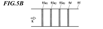
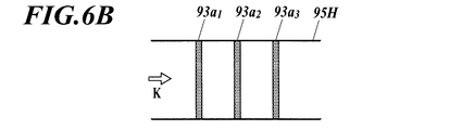
実施例,比較例のテストストリップ95,95Hに、アナライト(1)~(3)をそれぞれ含有する試料を滴下して展開させた後、このテストストリップ95,95H上で蛍光検出による画像撮影を行ったところ、図5B,図6Bに示すような画像が得られた。
実施例,比較例のテストストリップ95,95Hに、アナライト(1)~(3)をそれぞれ含有する試料を滴下して展開させた後、このテストストリップ95,95H上で蛍光検出による画像撮影を行ったところ、図5B,図6Bに示すような画像が得られた。
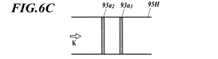
同様に、実施例,比較例のテストストリップ95,95Hに、アナライト(2),(3)をそれぞれ含有する試料を滴下して展開させた後、このテストストリップ95,95H上で蛍光検出による画像撮影を行ったところ、図5C,図6Cに示すような画像が得られた。
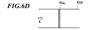
同様に、実施例,比較例のテストストリップ95,95Hに、アナライト(2)を含有する試料を滴下して展開させた後、このテストストリップ95,95H上で蛍光検出による画像撮影を行ったところ、図5D,図6Dに示すような画像が得られた。
[4.評価]
図5B~図5D,図6B~図6Dから明らかなように、マーカー94を設けたテストストリップ95では、マーカー94を設けていないテストストリップ95Hと同様に、アナライトが精度よく検出されることが分かる。また、テストストリップ95では、テストストリップ95Hと異なり、各テストライン93aの位置を正確に特定し、何れのテストライン93aから蛍光が検出されているかを容易に把握可能であることが分かる。
図5B~図5D,図6B~図6Dから明らかなように、マーカー94を設けたテストストリップ95では、マーカー94を設けていないテストストリップ95Hと同様に、アナライトが精度よく検出されることが分かる。また、テストストリップ95では、テストストリップ95Hと異なり、各テストライン93aの位置を正確に特定し、何れのテストライン93aから蛍光が検出されているかを容易に把握可能であることが分かる。
なお、明細書、請求の範囲、図面および要約を含む2012年11月14日に出願された日本語特許出願No.2012-249906号の全ての開示は、そのまま本出願の一部に組み込まれる。
以上のように、本発明は、検知対象領域の位置を正確に特定する必要のあるクロマトグラフィー試験片、クロマトグラフィー試験方法及びメンブレンに適している。
9,9A クロマトグラフィー試験片
93 検知対象領域
93a テストライン(検知対象領域)
93b コントロールライン(検知対象領域)
94,94A マーカー
96,96A メンブレン
900 スキャン領域
901 カバー部材
93 検知対象領域
93a テストライン(検知対象領域)
93b コントロールライン(検知対象領域)
94,94A マーカー
96,96A メンブレン
900 スキャン領域
901 カバー部材
Claims (21)
- 蛍光標識リガンドを用いたクロマトグラフィー試験で試料内のアナライトを検出または定量するために使用され、試料を供給されて所定の展開方向に展開させるとともに、蛍光の有無を検知するためのスキャンが行われるクロマトグラフィー試験片において、
スキャンの行われるスキャン領域内に、
前記展開方向に離間した状態で配設された、アナライトの有無または量を検知するための複数の検知対象領域と、
カチオン性の材料を含んで蛍光を生じるマーカーと、
を備えるクロマトグラフィー試験片。 - 請求項1記載のクロマトグラフィー試験片において、
前記マーカーは、カチオン性の蛍光体を含有するクロマトグラフィー試験片。 - 請求項2記載のクロマトグラフィー試験片において、
前記マーカーは、
前記蛍光体を担持する担体を含有するクロマトグラフィー試験片。 - 請求項1記載のクロマトグラフィー試験片において、
前記マーカーは、
蛍光体と、
前記蛍光体を担持するカチオン性の担体とを含有するクロマトグラフィー試験片。 - 請求項4記載のクロマトグラフィー試験片において、
前記蛍光体は、カチオン性であるクロマトグラフィー試験片。 - 請求項1~5の何れか一項に記載のクロマトグラフィー試験片において、
前記蛍光体は、インドシアニン骨格を有する化合物であるクロマトグラフィー試験片。 - 請求項1~6の何れか一項に記載のクロマトグラフィー試験片において、
前記マーカーは、
前記複数の検知対象領域のうち少なくとも1つの検知対象領域よりも前記展開方向の下流側に配設されているクロマトグラフィー試験片。 - 請求項7記載のクロマトグラフィー試験片において、
前記マーカーは、
前記複数の検知対象領域の全体よりも前記展開方向の下流側に配設されているクロマトグラフィー試験片。 - 請求項1~8の何れか一項に記載のクロマトグラフィー試験片において、
前記マーカーから生じる蛍光の波長領域と、
前記検知対象領域から生じる蛍光の波長領域とは、少なくとも1部の波長が重複するクロマトグラフィー試験片。 - 請求項1~9の何れか一項に記載のクロマトグラフィー試験片において、
供給される試料を伝わらせて前記展開方向に展開させるメンブレンを備え、
前記複数の検知対象領域及び前記マーカーは、前記メンブレンに設けられているクロマトグラフィー試験片。 - 請求項1~9の何れか一項に記載のクロマトグラフィー試験片において、
供給される試料を伝わらせて前記展開方向に展開させるメンブレンと、
前記メンブレンの上面を覆うカバー部材と、を備え、
前記複数の検知対象領域は、前記メンブレンに設けられ、
前記マーカーは、前記カバー部材に設けられているクロマトグラフィー試験片。 - 請求項1~11の何れか一項に記載のクロマトグラフィー試験片を用いて試料内のアナライトを検出または定量するクロマトグラフィー試験方法。
- 蛍光標識リガンドを用いたクロマトグラフィー試験で試料内のアナライトを検出または定量するために使用され、試料を供給されて所定の展開方向に展開させるとともに、蛍光の有無を検知するためのスキャンが行われるクロマトグラフィー試験片に備えられるメンブレンにおいて、
当該メンブレンは、
供給される試料を伝わらせて前記展開方向に展開させるものであり、
スキャンの行われるスキャン領域内に、
前記展開方向に離間した状態で配設された、アナライトの有無または量を検知するための複数の検知対象領域と、
カチオン性の材料を含んで蛍光を生じるマーカーと、
が設けられているメンブレン。 - 請求項13記載のメンブレンにおいて、
前記マーカーは、カチオン性の蛍光体を含有するメンブレン。 - 請求項14記載のメンブレンにおいて、
前記マーカーは、
前記蛍光体を担持する担体を含有するメンブレン。 - 請求項13記載のメンブレンにおいて、
前記マーカーは、
蛍光体と、
前記蛍光体を担持するカチオン性の担体とを含有するメンブレン。 - 請求項16記載のメンブレンにおいて、
前記蛍光体は、カチオン性であるメンブレン。 - 請求項13~17の何れか一項に記載のメンブレンにおいて、
前記蛍光体は、インドシアニン骨格を有する化合物であるメンブレン。 - 請求項13~18の何れか一項に記載のメンブレンにおいて、
前記マーカーは、
前記複数の検知対象領域のうち少なくとも1つの検知対象領域よりも前記展開方向の下流側に配設されているメンブレン。 - 請求項19記載のメンブレンにおいて、
前記マーカーは、
前記複数の検知対象領域よりも前記展開方向の下流側に配設されているメンブレン。 - 請求項13~20の何れか一項に記載のメンブレンにおいて、
前記マーカーから生じる蛍光の波長領域と、
前記検知対象領域から生じる蛍光の波長領域とは、少なくとも1部の波長が重複するメンブレン。
Priority Applications (1)
| Application Number | Priority Date | Filing Date | Title |
|---|---|---|---|
| JP2014546938A JPWO2014077142A1 (ja) | 2012-11-14 | 2013-11-01 | クロマトグラフィー試験片、クロマトグラフィー試験方法及びメンブレン |
Applications Claiming Priority (2)
| Application Number | Priority Date | Filing Date | Title |
|---|---|---|---|
| JP2012249906 | 2012-11-14 | ||
| JP2012-249906 | 2012-11-14 |
Publications (1)
| Publication Number | Publication Date |
|---|---|
| WO2014077142A1 true WO2014077142A1 (ja) | 2014-05-22 |
Family
ID=50731058
Family Applications (1)
| Application Number | Title | Priority Date | Filing Date |
|---|---|---|---|
| PCT/JP2013/079740 Ceased WO2014077142A1 (ja) | 2012-11-14 | 2013-11-01 | クロマトグラフィー試験片、クロマトグラフィー試験方法及びメンブレン |
Country Status (2)
| Country | Link |
|---|---|
| JP (1) | JPWO2014077142A1 (ja) |
| WO (1) | WO2014077142A1 (ja) |
Cited By (6)
| Publication number | Priority date | Publication date | Assignee | Title |
|---|---|---|---|---|
| JP2017538943A (ja) * | 2014-12-19 | 2017-12-28 | メルク パテント ゲゼルシャフト ミット ベシュレンクテル ハフツングMerck Patent Gesellschaft mit beschraenkter Haftung | クロマトグラフ試料を光学的に検知する方法及び装置 |
| WO2018043687A3 (ja) * | 2016-08-31 | 2018-04-26 | 積水化学工業株式会社 | 診断薬用蛍光粒子及びそれを用いた免疫測定試薬 |
| WO2018168907A1 (ja) * | 2017-03-14 | 2018-09-20 | デンカ生研株式会社 | 検体の展開を制御し得る、糖鎖抗原を抽出し測定するためのイムノクロマト試験片 |
| WO2019058903A1 (ja) * | 2017-09-20 | 2019-03-28 | 帝人株式会社 | クロマトグラフィー媒体用基材、クロマトグラフィー媒体及びイムノクロマトグラフ用ストリップ |
| JPWO2018179983A1 (ja) * | 2017-03-30 | 2019-04-11 | 帝人株式会社 | イムノクロマトグラフ用血球分離膜及びイムノクロマトグラフ用ストリップ |
| WO2022210312A1 (ja) * | 2021-04-01 | 2022-10-06 | 富士フイルム株式会社 | 検査装置 |
Citations (4)
| Publication number | Priority date | Publication date | Assignee | Title |
|---|---|---|---|---|
| JP2001004613A (ja) * | 1999-06-18 | 2001-01-12 | Matsushita Electric Ind Co Ltd | クロマトグラフィー分析装置 |
| WO2012086376A1 (ja) * | 2010-12-20 | 2012-06-28 | コニカミノルタオプト株式会社 | クロマトグラフィー分析装置 |
| JP2012198083A (ja) * | 2011-03-22 | 2012-10-18 | Konica Minolta Advanced Layers Inc | クロマトグラフィー分析装置及びクロマトグラフィー分析方法 |
| JP2012215494A (ja) * | 2011-04-01 | 2012-11-08 | Konica Minolta Medical & Graphic Inc | イムノクロマト測定法ならびにそれに用いられるキットおよびシステム |
-
2013
- 2013-11-01 JP JP2014546938A patent/JPWO2014077142A1/ja active Pending
- 2013-11-01 WO PCT/JP2013/079740 patent/WO2014077142A1/ja not_active Ceased
Patent Citations (4)
| Publication number | Priority date | Publication date | Assignee | Title |
|---|---|---|---|---|
| JP2001004613A (ja) * | 1999-06-18 | 2001-01-12 | Matsushita Electric Ind Co Ltd | クロマトグラフィー分析装置 |
| WO2012086376A1 (ja) * | 2010-12-20 | 2012-06-28 | コニカミノルタオプト株式会社 | クロマトグラフィー分析装置 |
| JP2012198083A (ja) * | 2011-03-22 | 2012-10-18 | Konica Minolta Advanced Layers Inc | クロマトグラフィー分析装置及びクロマトグラフィー分析方法 |
| JP2012215494A (ja) * | 2011-04-01 | 2012-11-08 | Konica Minolta Medical & Graphic Inc | イムノクロマト測定法ならびにそれに用いられるキットおよびシステム |
Cited By (12)
| Publication number | Priority date | Publication date | Assignee | Title |
|---|---|---|---|---|
| JP2017538943A (ja) * | 2014-12-19 | 2017-12-28 | メルク パテント ゲゼルシャフト ミット ベシュレンクテル ハフツングMerck Patent Gesellschaft mit beschraenkter Haftung | クロマトグラフ試料を光学的に検知する方法及び装置 |
| WO2018043687A3 (ja) * | 2016-08-31 | 2018-04-26 | 積水化学工業株式会社 | 診断薬用蛍光粒子及びそれを用いた免疫測定試薬 |
| JPWO2018043687A1 (ja) * | 2016-08-31 | 2019-08-15 | 積水化学工業株式会社 | 診断薬用蛍光粒子及びそれを用いた免疫測定試薬 |
| WO2018168907A1 (ja) * | 2017-03-14 | 2018-09-20 | デンカ生研株式会社 | 検体の展開を制御し得る、糖鎖抗原を抽出し測定するためのイムノクロマト試験片 |
| JP2018151331A (ja) * | 2017-03-14 | 2018-09-27 | デンカ生研株式会社 | 検体の展開を制御し得る、糖鎖抗原を抽出し測定するためのイムノクロマト試験片 |
| JPWO2018179983A1 (ja) * | 2017-03-30 | 2019-04-11 | 帝人株式会社 | イムノクロマトグラフ用血球分離膜及びイムノクロマトグラフ用ストリップ |
| WO2019058903A1 (ja) * | 2017-09-20 | 2019-03-28 | 帝人株式会社 | クロマトグラフィー媒体用基材、クロマトグラフィー媒体及びイムノクロマトグラフ用ストリップ |
| JPWO2019058903A1 (ja) * | 2017-09-20 | 2019-11-14 | 帝人株式会社 | クロマトグラフィー媒体用基材、クロマトグラフィー媒体及びイムノクロマトグラフ用ストリップ |
| WO2022210312A1 (ja) * | 2021-04-01 | 2022-10-06 | 富士フイルム株式会社 | 検査装置 |
| JPWO2022210312A1 (ja) * | 2021-04-01 | 2022-10-06 | ||
| US20240019427A1 (en) * | 2021-04-01 | 2024-01-18 | Fujifilm Corporation | Assay apparatus |
| JP7839149B2 (ja) | 2021-04-01 | 2026-04-01 | 富士フイルム株式会社 | 検査装置 |
Also Published As
| Publication number | Publication date |
|---|---|
| JPWO2014077142A1 (ja) | 2017-01-05 |
Similar Documents
| Publication | Publication Date | Title |
|---|---|---|
| JP6248030B2 (ja) | アナライトの検出または定量方法、アナライトを検出または定量するためのキット、およびアナライトを検出または定量するためのラテラルフロー型クロマト法用テストストリップ | |
| US10036750B2 (en) | Immunochromatography, and detection device and reagent for the same | |
| JP5994890B2 (ja) | アナライト検出プローブ | |
| US9726605B2 (en) | Fluorescence immuno-chromatography, kit and test strip for the same | |
| JP2013120120A (ja) | ラテラルフロー型クロマト法用テストストリップ、およびそれを用いたアナライトの検出または定量方法 | |
| JP5652393B2 (ja) | Spfs−lpfs系による測定方法に供するプラズモン励起センサおよびアッセイ法 | |
| WO2014077142A1 (ja) | クロマトグラフィー試験片、クロマトグラフィー試験方法及びメンブレン | |
| US11371987B2 (en) | Method of amplifying detection light using light-reflecting material, in immunochromatography | |
| JP2008216046A (ja) | ローカルプラズモン増強蛍光センサ | |
| JP5006459B1 (ja) | 標識用複合粒子 | |
| WO2014047737A1 (en) | Microfluidic chip for multi-analyte detection | |
| JP2010145272A (ja) | プラズモン励起センサを用いたアッセイ法 | |
| JP5825190B2 (ja) | アナライトを検出または定量するためのラテラルフロー型クロマト法用テストストリップ | |
| JP5480222B2 (ja) | 蛍光イムノクロマトグラフィー法、これに用いるキット及びテストストリップ | |
| JP2012215494A (ja) | イムノクロマト測定法ならびにそれに用いられるキットおよびシステム | |
| JP2008203172A (ja) | 表面プラズモン増強蛍光検出方法 | |
| JP7683852B2 (ja) | イムノクロマトアッセイ用メンブレン、イムノクロマトアッセイ用テストストリップ、および検査方法 | |
| KR102268785B1 (ko) | 표면에서 노로바이러스를 검출하기 위한 장치 및 방법 |
Legal Events
| Date | Code | Title | Description |
|---|---|---|---|
| 121 | Ep: the epo has been informed by wipo that ep was designated in this application |
Ref document number: 13854557 Country of ref document: EP Kind code of ref document: A1 |
|
| ENP | Entry into the national phase |
Ref document number: 2014546938 Country of ref document: JP Kind code of ref document: A |
|
| NENP | Non-entry into the national phase |
Ref country code: DE |
|
| 122 | Ep: pct application non-entry in european phase |
Ref document number: 13854557 Country of ref document: EP Kind code of ref document: A1 |