WO2014077057A1 - 光画像計測装置 - Google Patents
光画像計測装置 Download PDFInfo
- Publication number
- WO2014077057A1 WO2014077057A1 PCT/JP2013/077470 JP2013077470W WO2014077057A1 WO 2014077057 A1 WO2014077057 A1 WO 2014077057A1 JP 2013077470 W JP2013077470 W JP 2013077470W WO 2014077057 A1 WO2014077057 A1 WO 2014077057A1
- Authority
- WO
- WIPO (PCT)
- Prior art keywords
- image
- unit
- signal light
- tomographic
- tomographic image
- Prior art date
- Legal status (The legal status is an assumption and is not a legal conclusion. Google has not performed a legal analysis and makes no representation as to the accuracy of the status listed.)
- Ceased
Links
Images







Classifications
-
- G—PHYSICS
- G06—COMPUTING OR CALCULATING; COUNTING
- G06T—IMAGE DATA PROCESSING OR GENERATION, IN GENERAL
- G06T7/00—Image analysis
- G06T7/70—Determining position or orientation of objects or cameras
- G06T7/73—Determining position or orientation of objects or cameras using feature-based methods
-
- A—HUMAN NECESSITIES
- A61—MEDICAL OR VETERINARY SCIENCE; HYGIENE
- A61B—DIAGNOSIS; SURGERY; IDENTIFICATION
- A61B3/00—Apparatus for testing the eyes; Instruments for examining the eyes
- A61B3/10—Objective types, i.e. instruments for examining the eyes independent of the patients' perceptions or reactions
- A61B3/12—Objective types, i.e. instruments for examining the eyes independent of the patients' perceptions or reactions for looking at the eye fundus, e.g. ophthalmoscopes
-
- A—HUMAN NECESSITIES
- A61—MEDICAL OR VETERINARY SCIENCE; HYGIENE
- A61B—DIAGNOSIS; SURGERY; IDENTIFICATION
- A61B3/00—Apparatus for testing the eyes; Instruments for examining the eyes
- A61B3/0016—Operational features thereof
- A61B3/0025—Operational features thereof characterised by electronic signal processing, e.g. eye models
-
- A—HUMAN NECESSITIES
- A61—MEDICAL OR VETERINARY SCIENCE; HYGIENE
- A61B—DIAGNOSIS; SURGERY; IDENTIFICATION
- A61B3/00—Apparatus for testing the eyes; Instruments for examining the eyes
- A61B3/10—Objective types, i.e. instruments for examining the eyes independent of the patients' perceptions or reactions
- A61B3/1005—Objective types, i.e. instruments for examining the eyes independent of the patients' perceptions or reactions for measuring distances inside the eye, e.g. thickness of the cornea
-
- A—HUMAN NECESSITIES
- A61—MEDICAL OR VETERINARY SCIENCE; HYGIENE
- A61B—DIAGNOSIS; SURGERY; IDENTIFICATION
- A61B3/00—Apparatus for testing the eyes; Instruments for examining the eyes
- A61B3/10—Objective types, i.e. instruments for examining the eyes independent of the patients' perceptions or reactions
- A61B3/102—Objective types, i.e. instruments for examining the eyes independent of the patients' perceptions or reactions for optical coherence tomography [OCT]
-
- A—HUMAN NECESSITIES
- A61—MEDICAL OR VETERINARY SCIENCE; HYGIENE
- A61B—DIAGNOSIS; SURGERY; IDENTIFICATION
- A61B3/00—Apparatus for testing the eyes; Instruments for examining the eyes
- A61B3/10—Objective types, i.e. instruments for examining the eyes independent of the patients' perceptions or reactions
- A61B3/12—Objective types, i.e. instruments for examining the eyes independent of the patients' perceptions or reactions for looking at the eye fundus, e.g. ophthalmoscopes
- A61B3/1225—Objective types, i.e. instruments for examining the eyes independent of the patients' perceptions or reactions for looking at the eye fundus, e.g. ophthalmoscopes using coherent radiation
-
- A—HUMAN NECESSITIES
- A61—MEDICAL OR VETERINARY SCIENCE; HYGIENE
- A61B—DIAGNOSIS; SURGERY; IDENTIFICATION
- A61B3/00—Apparatus for testing the eyes; Instruments for examining the eyes
- A61B3/10—Objective types, i.e. instruments for examining the eyes independent of the patients' perceptions or reactions
- A61B3/14—Arrangements specially adapted for eye photography
- A61B3/15—Arrangements specially adapted for eye photography with means for aligning, spacing or blocking spurious reflection ; with means for relaxing
- A61B3/152—Arrangements specially adapted for eye photography with means for aligning, spacing or blocking spurious reflection ; with means for relaxing for aligning
-
- G—PHYSICS
- G01—MEASURING; TESTING
- G01B—MEASURING LENGTH, THICKNESS OR SIMILAR LINEAR DIMENSIONS; MEASURING ANGLES; MEASURING AREAS; MEASURING IRREGULARITIES OF SURFACES OR CONTOURS
- G01B9/00—Measuring instruments characterised by the use of optical techniques
- G01B9/02—Interferometers
- G01B9/0209—Low-coherence interferometers
- G01B9/02091—Tomographic interferometers, e.g. based on optical coherence
-
- G—PHYSICS
- G02—OPTICS
- G02B—OPTICAL ELEMENTS, SYSTEMS OR APPARATUS
- G02B27/00—Optical systems or apparatus not provided for by any of the groups G02B1/00 - G02B26/00, G02B30/00
- G02B27/0075—Optical systems or apparatus not provided for by any of the groups G02B1/00 - G02B26/00, G02B30/00 with means for altering, e.g. increasing, the depth of field or depth of focus
-
- G—PHYSICS
- G06—COMPUTING OR CALCULATING; COUNTING
- G06T—IMAGE DATA PROCESSING OR GENERATION, IN GENERAL
- G06T11/00—Two-dimensional [2D] image generation
- G06T11/60—Creating or editing images; Combining images with text
-
- G—PHYSICS
- G06—COMPUTING OR CALCULATING; COUNTING
- G06T—IMAGE DATA PROCESSING OR GENERATION, IN GENERAL
- G06T2207/00—Indexing scheme for image analysis or image enhancement
- G06T2207/10—Image acquisition modality
- G06T2207/10072—Tomographic images
- G06T2207/10101—Optical tomography; Optical coherence tomography [OCT]
-
- G—PHYSICS
- G06—COMPUTING OR CALCULATING; COUNTING
- G06T—IMAGE DATA PROCESSING OR GENERATION, IN GENERAL
- G06T2207/00—Indexing scheme for image analysis or image enhancement
- G06T2207/30—Subject of image; Context of image processing
- G06T2207/30004—Biomedical image processing
- G06T2207/30041—Eye; Retina; Ophthalmic
Definitions
- the present invention relates to an optical image measurement technique for acquiring an image of an object using optical coherence tomography (OCT).
- OCT optical coherence tomography
- OCT that forms an image representing the surface form or internal form of an object using a light beam from a laser light source or the like has attracted attention. Since OCT has no invasiveness to the human body like X-ray CT, it is expected to be applied particularly in the medical field and the biological field. For example, in the field of ophthalmology, an apparatus for forming an image of the fundus oculi or cornea has been put into practical use.
- Patent Document 1 discloses an apparatus using a so-called “Fourier Domain OCT (Fourier Domain OCT)” technique. That is, this device irradiates a target with a beam of low coherence light, superimposes the reflected light and reference light to generate interference light, acquires the spectral intensity distribution of this interference light, and performs Fourier transform Is used to image the form of the object in the depth direction (z direction). Further, this apparatus includes a galvanometer mirror that scans a light beam (signal light) in one direction (x direction) orthogonal to the z direction, thereby forming an image of a desired measurement target region of the object. ing.
- Fourier Domain OCT Frourier Domain OCT
- An image formed by this apparatus is a two-dimensional tomographic image in the depth direction (z direction) along the scanning direction (x direction) of the light beam.
- This method is also called a spectral domain.
- a spectral domain type OCT apparatus is also disclosed in Patent Document 2.
- Patent Document 3 the wavelength of light irradiated on an object is scanned (wavelength sweep), and interference intensity obtained by superimposing reflected light of each wavelength and reference light is detected to obtain a spectral intensity distribution.
- An OCT apparatus is described that obtains an image of the form of an object by performing Fourier transform on the acquired image.
- Such an OCT apparatus is called a swept source type.
- the swept source type is a kind of Fourier domain type.
- Patent Document 4 discloses a configuration in which OCT is applied to the ophthalmic field.
- An apparatus using OCT has an advantage in that a high-definition image can be acquired, and further, a tomographic image and a three-dimensional image can be acquired.
- a conventional OCT apparatus uses an optical system having a large NA (Numerical Aperture) in order to improve the lateral resolution.
- NA Numerical Aperture
- the depth of focus becomes shallow, and blurring tends to occur in the image. That is, the lateral resolution and the sharpness of the entire image are in a trade-off relationship, and it has been difficult to achieve both of them with the conventional technology.
- An object of the present invention is to provide a technique capable of acquiring a high overall lateral resolution and a sharp image.
- the invention according to claim 1 includes a scanning unit that changes the irradiation position of the signal light on the object, and a focusing position changing unit that changes the focusing position of the signal light, An image that forms a tomographic image based on an optical system that detects interference light between the return light from the object of each signal light and the reference light and a plurality of interference light detection results corresponding to a plurality of irradiation positions of the signal light A control unit that repeatedly irradiates the plurality of irradiation positions with the signal light while changing the in-focus position by controlling the optical system, and a result of the repeated signal light irradiation; And a combined tomographic image forming unit that forms one combined tomographic image based on two or more tomographic images formed by the image forming unit.
- the invention according to claim 2 is the optical image measurement device according to claim 1, wherein the synthetic tomographic image forming unit corresponds to a corresponding in-focus position for each of the two or more tomographic images. And a partial image specifying unit that specifies a partial image including the image region to be formed, and the combined tomographic image is formed by combining the two or more specified partial images.
- the invention according to claim 3 is the optical image measurement device according to claim 2, wherein the synthetic tomographic image forming unit analyzes the two or more partial images to thereby analyze the two or more parts.
- a position adjustment unit that adjusts the relative position of the image is included, and the combined tomographic image is formed by combining the two or more partial images that have been adjusted in relative position.
- the invention according to claim 4 is the optical image measurement device according to claim 3, wherein the position adjustment unit analyzes each of the two or more partial images to thereby obtain a characteristic part of the target object. Including a feature image region specifying unit that specifies a feature image region corresponding to the above, and adjusting the relative positions of the two or more partial images based on the specified feature image region.
- the invention according to claim 5 is the optical image measurement device according to any one of claims 1 to 4, wherein the optical system and the object are repeatedly exposed during repetitive signal light irradiation. A displacement detection unit for detecting displacement; the control unit newly executes repetitive signal light irradiation based on the detected displacement; and the synthetic tomographic image forming unit is newly executed.
- the composite tomographic image is formed based on two or more new tomographic images formed based on the result of repetitive signal light irradiation.
- the invention according to claim 6 is the optical image measurement device according to any one of claims 1 to 4, wherein the optical system and the object are repeatedly exposed during repetitive signal light irradiation. It has a displacement detection part which detects a displacement, The control part makes report part output report information based on detected displacement, It is characterized by the above-mentioned.
- the invention according to claim 7 is the optical image measurement device according to any one of claims 1 to 6, wherein the optical image measurement device is repetitive based on the thickness of the predetermined layer of the object acquired in advance.
- the invention according to claim 8 is the optical image measurement device according to claim 7, wherein the predetermined layer is analyzed by analyzing a tomographic image acquired before repetitive signal light irradiation. It has a layer thickness calculation part which calculates thickness.
- the invention according to claim 9 is the optical image measurement device according to claim 7 or claim 8, wherein the optical system includes a numerical aperture changing unit that changes the numerical aperture, and the depth of focus is A numerical aperture determining unit configured to determine a numerical aperture value to be less than a predetermined layer thickness; and the control unit controls the numerical aperture changing unit to set the numerical aperture to the determined value. It is characterized by that.
- the invention according to claim 10 is the optical image measurement device according to any one of claims 1 to 9, wherein the control unit is configured to perform the plurality of the plurality of signal lights in the repetitive signal light irradiation.
- the focus position is changed stepwise for each repetition of the signal light irradiation with respect to the irradiation position, and the combined tomographic image forming unit has a rectangular shape including an image area corresponding to the corresponding focus position in each tomographic image.
- the synthetic tomographic image is formed based on the partial image.
- the invention according to claim 11 is the optical image measurement device according to any one of claims 1 to 9, wherein the control unit performs the focusing in repetitive signal light irradiation.
- the position is continuously changed, and the synthetic tomographic image forming unit forms the synthetic tomographic image in each tomographic image based on a parallelogram partial image including an image region corresponding to a corresponding in-focus position. It is characterized by.
- the invention according to claim 12 is the optical image measurement device according to any one of claims 1 to 11, wherein the composite tomographic image forming unit is configured to each of the two or more tomographic images.
- the invention according to claim 13 is the optical image measurement device according to any one of claims 1 to 11, wherein the composite tomographic image forming unit is configured to receive each of the two or more tomographic images.
- optical image measurement device forms a tomographic image or a three-dimensional image of an object using OCT.
- images acquired by OCT may be collectively referred to as OCT images.
- a measurement operation for forming an OCT image may be referred to as OCT measurement.
- OCT measurement it is possible to use suitably the description content of the literature described in this specification as the content of the following embodiment. Also, various configurations described in the following embodiments and modifications can be arbitrarily combined.
- a fundus oculi observation device that performs OCT measurement of the fundus by applying Fourier domain type OCT with the object being an eye to be examined (fundus)
- the fundus oculi observation device can acquire both an OCT image and a fundus image of the fundus using a spectral domain OCT technique.
- the configuration according to the present invention can be applied to an optical image measurement apparatus using a type other than the spectral domain, for example, a swept source OCT technique.
- an apparatus combining an OCT apparatus and a fundus camera will be described.
- a fundus imaging apparatus other than the fundus camera for example, an SLO, a slit lamp, an ophthalmic surgical microscope, and the like has a configuration according to this embodiment. It is also possible to combine OCT apparatuses. In addition, the configuration according to this embodiment can be incorporated into a single OCT apparatus.
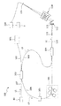
- the fundus oculi observation device (optical image measurement device) 1 includes a fundus camera unit 2, an OCT unit 100, and an arithmetic control unit 200.
- the retinal camera unit 2 has almost the same optical system as a conventional retinal camera.
- the OCT unit 100 is provided with an optical system for acquiring an OCT image of the fundus.
- the arithmetic control unit 200 includes a computer that executes various arithmetic processes and control processes.
- the fundus camera unit 2 shown in FIG. 1 is provided with an optical system for obtaining a two-dimensional image (fundus image) representing the surface form of the fundus oculi Ef of the eye E to be examined.
- the fundus image includes an observation image and a captured image.
- the observation image is, for example, a monochrome moving image formed at a predetermined frame rate using near infrared light.
- the captured image may be, for example, a color image obtained by flashing visible light, or a monochrome still image using near infrared light or visible light as illumination light.
- the fundus camera unit 2 may be configured to be able to acquire images other than these, such as a fluorescein fluorescent image, an indocyanine green fluorescent image, a spontaneous fluorescent image, and the like.
- the fundus camera unit 2 is provided with a chin rest and a forehead for supporting the subject's face. Further, the fundus camera unit 2 is provided with an illumination optical system 10 and a photographing optical system 30.
- the illumination optical system 10 irradiates the fundus oculi Ef with illumination light.
- the photographing optical system 30 guides the fundus reflection light of the illumination light to an imaging device (CCD image sensor (sometimes simply referred to as a CCD) 35, 38).
- CCD image sensor sometimes simply referred to as a CCD
- the observation light source 11 of the illumination optical system 10 is composed of, for example, a halogen lamp.
- the light (observation illumination light) output from the observation light source 11 is reflected by the reflection mirror 12 having a curved reflection surface, passes through the condensing lens 13, passes through the visible cut filter 14, and is converted into near infrared light. Become. Further, the observation illumination light is once converged in the vicinity of the photographing light source 15, reflected by the mirror 16, and passes through the relay lenses 17 and 18, the diaphragm 19 and the relay lens 20. Then, the observation illumination light is reflected at the peripheral portion (region around the hole portion) of the aperture mirror 21, passes through the dichroic mirror 46, and is refracted by the objective lens 22 to illuminate the fundus oculi Ef.
- An LED Light Emitting Diode
- the fundus reflection light of the observation illumination light is refracted by the objective lens 22, passes through the dichroic mirror 46, passes through the hole formed in the central region of the perforated mirror 21, passes through the dichroic mirror 55, and is a focusing lens. It is reflected by the mirror 32 via 31. Further, the fundus reflection light passes through the half mirror 39A, is reflected by the dichroic mirror 33, and forms an image on the light receiving surface of the CCD image sensor 35 by the condenser lens.
- the CCD image sensor 35 detects fundus reflected light at a predetermined frame rate, for example. On the display device 3, an image (observation image) based on fundus reflection light detected by the CCD image sensor 35 is displayed. In addition, when the focus (focus) of the photographing optical system is adjusted to the anterior segment, an observation image of the anterior segment of the eye E is displayed.
- the photographing light source 15 is constituted by, for example, a xenon lamp.
- the light (imaging illumination light) output from the imaging light source 15 is applied to the fundus oculi Ef through the same path as the observation illumination light.
- the fundus reflection light of the imaging illumination light is guided to the dichroic mirror 33 through the same path as that of the observation illumination light, passes through the dichroic mirror 33, is reflected by the mirror 36, and is reflected by the condenser lens 37 of the CCD image sensor 38.
- An image is formed on the light receiving surface.
- On the display device 3 an image (captured image) based on fundus reflection light detected by the CCD image sensor 38 is displayed.
- the display device 3 that displays the observation image and the display device 3 that displays the captured image may be the same or different.
- an infrared captured image is displayed. It is also possible to use an LED as a photographing light source.
- the LCD (Liquid Crystal Display) 39 displays a fixation target and an eyesight measurement index.
- the fixation target is an index for fixing the eye E to be examined, and is used at the time of fundus photographing or OCT measurement.
- a part of the light output from the LCD 39 is reflected by the half mirror 39A, reflected by the mirror 32, passes through the focusing lens 31 and the dichroic mirror 55, passes through the hole of the perforated mirror 21, and reaches the dichroic.
- the light passes through the mirror 46, is refracted by the objective lens 22, and is projected onto the fundus oculi Ef.
- the fixation position of the eye E can be changed by changing the display position of the fixation target on the screen of the LCD 39.
- As the fixation position of the eye E for example, a position for acquiring an image centered on the macular portion of the fundus oculi Ef, or a position for acquiring an image centered on the optic disc as in the case of a conventional fundus camera And a position for acquiring an image centered on the fundus center between the macula and the optic disc. It is also possible to arbitrarily change the display position of the fixation target.
- the fundus camera unit 2 is provided with an alignment optical system 50 and a focus optical system 60 as in the conventional fundus camera.
- the alignment optical system 50 generates an index (alignment index) for performing alignment (alignment) of the apparatus optical system with respect to the eye E.
- the focus optical system 60 generates an index (split index) for focusing on the fundus oculi Ef.
- the light (alignment light) output from the LED 51 of the alignment optical system 50 is reflected by the dichroic mirror 55 via the apertures 52 and 53 and the relay lens 54, passes through the hole of the perforated mirror 21, and reaches the dichroic mirror 46. And is projected onto the cornea of the eye E by the objective lens 22.
- the corneal reflection light of the alignment light passes through the objective lens 22, the dichroic mirror 46 and the hole, part of which passes through the dichroic mirror 55, passes through the focusing lens 31, is reflected by the mirror 32, and is half mirror
- the light passes through 39A, is reflected by the dichroic mirror 33, and is projected onto the light receiving surface of the CCD image sensor 35 by the condenser lens.
- the light reception image (alignment index) by the CCD image sensor 35 is displayed on the display device 3 together with the observation image.
- the user performs alignment by performing the same operation as that of a conventional fundus camera. Further, the arithmetic control unit 200 may perform alignment by analyzing the position of the alignment index and moving the optical system (auto-alignment function).
- the reflecting surface of the reflecting rod 67 is obliquely provided on the optical path of the illumination optical system 10.
- the light (focus light) output from the LED 61 of the focus optical system 60 passes through the relay lens 62, is separated into two light beams by the split indicator plate 63, passes through the two-hole aperture 64, and is reflected by the mirror 65, The light is focused on the reflecting surface of the reflecting bar 67 by the condenser lens 66 and reflected. Further, the focus light passes through the relay lens 20, is reflected by the perforated mirror 21, passes through the dichroic mirror 46, is refracted by the objective lens 22, and is projected onto the fundus oculi Ef.
- the fundus reflection light of the focus light is detected by the CCD image sensor 35 through the same path as the corneal reflection light of the alignment light.
- a light reception image (split index) by the CCD image sensor 35 is displayed on the display device 3 together with the observation image.
- the arithmetic and control unit 200 analyzes the position of the split index and moves the focusing lens 31 and the focus optical system 60 to perform focusing as in the conventional case (autofocus function). Alternatively, focusing may be performed manually while visually checking the split indicator.
- the dichroic mirror 46 combines the optical path for fundus imaging and the optical path for OCT measurement.
- the dichroic mirror 46 reflects light in a wavelength band used for OCT measurement and transmits light for fundus photographing.
- a collimator lens unit 40, an optical path length changing unit 41, a galvano scanner 42, a focusing lens 43, a mirror 44, and a relay lens 45 are provided in this order from the OCT unit 100 side. ing.
- the members arranged in the optical path for OCT measurement and the members included in the OCT unit 100 are examples of the “optical system”.
- the collimator lens unit 40 turns the light (signal light LS) emitted from the optical fiber 107 into a parallel light flux. Further, the collimator lens unit 40 causes the return light of the signal light LS from the eye E to be incident on the optical fiber 107.
- the collimator lens unit 40 is provided with a numerical aperture changing unit 40A that changes the numerical aperture (NA) in OCT measurement by changing the beam diameter of the parallel light flux.
- the numerical aperture changing unit 40A is configured by, for example, a unit capable of selectively arranging a plurality of lenses having different refractive powers in the optical path, or a unit capable of moving the lenses along the optical axis direction.
- the numerical aperture in OCT measurement is changed by changing the beam diameter of the signal light LS.
- the optical path length changing unit 41 is movable in the direction of the arrow shown in FIG. 1, and changes the optical path length of the optical path for OCT measurement. This change in the optical path length is used for correcting the optical path length according to the axial length of the eye E or adjusting the interference state.
- the optical path length changing unit 41 includes, for example, a corner cube and a mechanism for moving the corner cube.
- the galvano scanner 42 changes the traveling direction of light (signal light LS) passing through the optical path for OCT measurement. Thereby, the fundus oculi Ef can be scanned with the signal light LS.
- the galvano scanner 42 includes, for example, a galvano mirror that scans the signal light LS in the x direction, a galvano mirror that scans in the y direction, and a mechanism that drives these independently. Thereby, the signal light LS can be scanned in an arbitrary direction on the xy plane.
- the focusing lens 43 is movable in the direction of the arrow shown in FIG. 1, and changes the focus position (focus position) in OCT measurement.
- the OCT unit 100 is provided with an optical system for acquiring an OCT image of the fundus oculi Ef.
- This optical system has the same configuration as a conventional spectral domain type OCT apparatus. That is, this optical system divides low-coherence light into reference light and signal light, and generates interference light by causing interference between the signal light passing through the fundus oculi Ef and the reference light passing through the reference optical path. It is configured to detect spectral components. This detection result (detection signal) is sent to the arithmetic control unit 200.
- a wavelength swept light source is provided instead of a light source that outputs a low coherence light source, and an optical member that spectrally decomposes interference light is not provided.
- a known technique according to the type of optical coherence tomography can be arbitrarily applied.
- the light source unit 101 outputs a broadband low-coherence light L0.
- the low coherence light L0 includes, for example, a near-infrared wavelength band (about 800 nm to 900 nm) and has a temporal coherence length of about several tens of micrometers. Note that near-infrared light having a wavelength band invisible to the human eye, for example, a center wavelength of about 1040 to 1060 nm, may be used as the low-coherence light L0.
- the light source unit 101 includes a super luminescent diode (Super Luminescent Diode: SLD), an LED, and an optical output device such as an SOA (Semiconductor Optical Amplifier).
- SLD Super Luminescent Diode
- LED an LED
- SOA semiconductor Optical Amplifier
- the low coherence light L0 output from the light source unit 101 is guided to the fiber coupler 103 by the optical fiber 102, and is divided into the signal light LS and the reference light LR.
- the reference light LR is guided by the optical fiber 104 and reaches an optical attenuator (attenuator) 105.
- the optical attenuator 105 automatically adjusts the amount of the reference light LR guided to the optical fiber 104 under the control of the arithmetic control unit 200 using a known technique.
- the reference light LR whose light amount has been adjusted by the optical attenuator 105 is guided by the optical fiber 104 and reaches the polarization adjuster (polarization controller) 106.
- the polarization adjuster 106 is, for example, a device that adjusts the polarization state of the reference light LR guided in the optical fiber 104 by applying a stress from the outside to the optical fiber 104 in a loop shape.
- the configuration of the polarization adjuster 106 is not limited to this, and any known technique can be used.
- the reference light LR whose polarization state is adjusted by the polarization adjuster 106 reaches the fiber coupler 109.
- the signal light LS generated by the fiber coupler 103 is guided by the optical fiber 107 and converted into a parallel light beam by the collimator lens unit 40. Further, the signal light LS reaches the dichroic mirror 46 via the optical path length changing unit 41, the galvano scanner 42, the focusing lens 43, the mirror 44, and the relay lens 45. The signal light LS is reflected by the dichroic mirror 46, is refracted by the objective lens 22, and is applied to the fundus oculi Ef. The signal light LS is scattered (including reflection) at various depth positions of the fundus oculi Ef.
- the backscattered light (return light) of the signal light LS from the fundus oculi Ef travels in the same direction as the forward path in the reverse direction, is guided to the fiber coupler 103, and reaches the fiber coupler 109 via the optical fiber.
- the fiber coupler 109 causes the backscattered light of the signal light LS and the reference light LR that has passed through the optical fiber 104 to interfere with each other.
- the interference light LC generated thereby is guided by the optical fiber 110 and emitted from the emission end 111. Further, the interference light LC is converted into a parallel light beam by the collimator lens 112, dispersed (spectral decomposition) by the diffraction grating 113, condensed by the condenser lens 114, and projected onto the light receiving surface of the CCD image sensor 115.
- the diffraction grating 113 shown in FIG. 2 is a transmission type, other types of spectroscopic elements such as a reflection type diffraction grating may be used.
- the CCD image sensor 115 is a line sensor, for example, and detects each spectral component of the split interference light LC and converts it into electric charges.
- the CCD image sensor 115 accumulates this electric charge, generates a detection signal, and sends it to the arithmetic control unit 200.
- a Michelson type interferometer is used, but any type of interferometer such as a Mach-Zehnder type can be appropriately used.
- any type of interferometer such as a Mach-Zehnder type can be appropriately used.
- another form of image sensor for example, a CMOS (Complementary Metal Oxide Semiconductor) image sensor or the like can be used.
- CMOS Complementary Metal Oxide Semiconductor
- the configuration of the arithmetic control unit 200 will be described.
- the arithmetic control unit 200 analyzes the detection signal input from the CCD image sensor 115 and forms an OCT image of the fundus oculi Ef.
- the arithmetic processing for this is the same as that of a conventional spectral domain type OCT apparatus.
- the arithmetic control unit 200 controls each part of the fundus camera unit 2, the display device 3, and the OCT unit 100. For example, the arithmetic control unit 200 displays an OCT image of the fundus oculi Ef on the display device 3.
- the arithmetic control unit 200 controls the operation of the observation light source 11, the imaging light source 15 and the LEDs 51 and 61, the operation control of the LCD 39, the movement control of the focusing lenses 31 and 43, and the reflector 67. Movement control, movement control of the focus optical system 60, operation control of the numerical aperture changing unit 40A, movement control of the optical path length changing unit 41, operation control of the galvano scanner 42, and the like are performed.
- the arithmetic control unit 200 performs operation control of the light source unit 101, operation control of the optical attenuator 105, operation control of the polarization adjuster 106, operation control of the CCD image sensor 115, and the like.
- the arithmetic control unit 200 includes, for example, a microprocessor, a RAM, a ROM, a hard disk drive, a communication interface, and the like, as in a conventional computer.
- a computer program for controlling the fundus oculi observation device 1 is stored in a storage device such as a hard disk drive.
- the arithmetic control unit 200 may include various circuit boards, for example, a circuit board for forming an OCT image.
- the arithmetic control unit 200 may include an operation device (input device) such as a keyboard and a mouse, and a display device such as an LCD.
- the fundus camera unit 2, the display device 3, the OCT unit 100, and the calculation control unit 200 may be configured integrally (that is, in a single housing) or separated into two or more cases. It may be.
- Control system The configuration of the control system of the fundus oculi observation device 1 will be described with reference to FIGS.
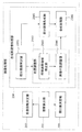
- the control system of the fundus oculi observation device 1 is configured around the control unit 210.
- the control unit 210 includes, for example, the aforementioned microprocessor, RAM, ROM, hard disk drive, communication interface, and the like.
- the control unit 210 is provided with a main control unit 211 and a storage unit 212.
- the main control unit 211 performs the various controls described above.
- the main control unit 211 controls the focusing drive unit 31A, the numerical aperture changing unit 40A, the optical path length changing unit 41, the galvano scanner 42, and the focusing driving unit 43A of the fundus camera unit 2.
- the main control unit 211 also controls the light source unit 101, the optical attenuator 105, and the polarization adjuster 106 of the OCT unit 100.
- the focusing drive unit 31A moves the focusing lens 31 in the optical axis direction. Thereby, the focus position of the photographic optical system 30 is changed.
- the focusing drive unit 43A moves the focusing lens 43 along the optical axis. Thereby, the focus position of the optical system for OCT measurement is changed.
- the in-focus position defines the amount of the signal light LS incident on the optical fiber 107 via the collimator lens unit 40. That is, the optimum focusing position is realized by arranging the focusing lens 43 at a position where the fiber end of the optical fiber 107 on the collimator lens unit 40 side and the fundus oculi Ef are optically conjugate.
- Each of the focusing driving unit 31A and the focusing driving unit 43A includes an actuator such as a pulse motor and a mechanism for transmitting the driving force generated by the actuator to the focusing lens 43.
- the main control unit 211 can also control an optical system drive unit (not shown) to move the optical system provided in the fundus camera unit 2 three-dimensionally. This control is used in alignment and tracking. Tracking is to move the apparatus optical system in accordance with the eye movement of the eye E. When tracking is performed, alignment and focusing are performed in advance. Tracking is a function of maintaining a suitable positional relationship in which the alignment and focus are achieved by causing the position of the apparatus optical system to follow the eye movement.
- the main control unit 211 performs a process of writing data to the storage unit 212 and a process of reading data from the storage unit 212.
- the storage unit 212 stores various data. Examples of the data stored in the storage unit 212 include OCT image image data, fundus image data, and examined eye information.
- the eye information includes information about the subject such as patient ID and name, and information about the eye such as left / right eye identification information.
- the storage unit 212 stores various programs and data for operating the fundus oculi observation device 1.
- the image forming unit 220 forms tomographic image data of the fundus oculi Ef based on the detection signal from the CCD image sensor 115. This process includes processes such as noise removal (noise reduction), filter processing, dispersion compensation, and FFT (Fast Fourier Transform) as in the conventional spectral domain type optical coherence tomography. In the case of another type of OCT apparatus, the image forming unit 220 executes a known process corresponding to the type.
- the image forming unit 220 includes, for example, the circuit board described above. In this specification, “image data” and “image” based thereon may be identified.
- the image processing unit 230 performs various types of image processing and analysis processing on the image formed by the image forming unit 220. For example, the image processing unit 230 executes various correction processes such as image brightness correction. The image processing unit 230 performs various types of image processing and analysis processing on the image (fundus image, anterior eye image, etc.) obtained by the fundus camera unit 2.
- the image processing unit 230 executes known image processing such as interpolation processing for interpolating pixels between tomographic images to form image data of a three-dimensional image of the fundus oculi Ef.
- image data of a three-dimensional image means image data in which pixel positions are defined by a three-dimensional coordinate system.
- image data of a three-dimensional image there is image data composed of voxels arranged three-dimensionally. This image data is called volume data or voxel data.
- the image processing unit 230 When displaying an image based on volume data, the image processing unit 230 performs a rendering process (such as volume rendering or MIP (Maximum Intensity Projection)) on the volume data, and views the image from a specific line-of-sight direction.
- Image data of a pseudo three-dimensional image is formed. This pseudo three-dimensional image is displayed on a display device such as the display unit 240A.
- stack data of a plurality of tomographic images is image data of a three-dimensional image.
- the stack data is image data obtained by three-dimensionally arranging a plurality of tomographic images obtained along a plurality of scanning lines based on the positional relationship of the scanning lines. That is, stack data is image data obtained by expressing a plurality of tomographic images originally defined by individual two-dimensional coordinate systems by one three-dimensional coordinate system (that is, by embedding them in one three-dimensional space). is there.
- the image processing unit 230 includes a layer thickness calculation unit 231, an iteration number determination unit 232, a numerical aperture determination unit 233, and a synthetic tomographic image formation unit 234.
- the layer thickness calculation unit 231 calculates the thickness of the predetermined layer of the fundus oculi Ef by analyzing the tomographic image of the fundus oculi Ef. This process includes a process of specifying a boundary (upper end and lower end) of a predetermined layer of the fundus oculi Ef and a process of obtaining a distance between the specified upper end and lower end.
- the predetermined layer indicates a layer of the fundus oculi Ef to be observed.
- the layer tissue of the fundus oculi Ef includes the retina, choroid and sclera.
- the retina has a multi-layered structure, including inner boundary membrane, nerve fiber layer, ganglion cell layer, inner plexiform layer inner granular layer, outer reticular layer, outer granular layer, outer boundary membrane, photoreceptor layer and retinal pigment Has an epithelial layer.
- the predetermined layer the retina, choroid or sclera, or one or more layer tissues included in the retina are applied.
- the predetermined layer is set in advance. Further, the predetermined layer may be arbitrarily set.
- segmentation is image processing for specifying an image region in a tomographic image corresponding to the layer structure of the fundus oculi Ef. This process is performed based on the pixel value (luminance value) of the tomographic image.
- Each layer structure of the fundus oculi Ef has a characteristic reflectance, and an image region of the layer structure also has a characteristic luminance value.
- a target image area is specified based on such characteristic luminance values. It is also possible to specify the surface of the fundus oculi Ef (the boundary between the retina and the vitreous body) and specify the target image area based on the distance from the surface position.
- the layer thickness calculation unit 231 obtains, for example, the number of pixels between the upper end and the lower end, and determines the thickness of the predetermined layer based on the number of pixels.
- the information indicating the thickness of the predetermined layer may be the number of pixels itself, or distance information obtained from the number of pixels (e.g., conversion to a distance in real space).
- the layer thickness information may be information indicating a thickness distribution in a predetermined layer, or information statistically obtained from the thickness distribution (average value, mode value, median value, maximum value, minimum value, etc.) Good.
- the thickness of a predetermined position of a predetermined layer may be used as the layer thickness information.
- the iteration number determination unit 232 determines the number of scan iterations in OCT measurement based on the layer thickness information acquired by the layer thickness calculation unit 231. Although details will be described later, the OCT measurement of this embodiment is to repeatedly scan the same portion of the fundus oculi Ef while changing the focus position. The number of iterations determined by the iteration number determination unit 232 corresponds to the number of tomographic images obtained by such OCT measurement. Further, when the focus position is changed stepwise in such OCT measurement, the number of repetitions corresponds to the number of focus positions to be changed.
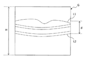
- the retinal thickness d that is, between the retina surface (boundary between the inner limiting membrane and the vitreous body) L1 and the retina bottom (boundary between the retinal pigment epithelial layer and the choroid) L2 Is obtained.
- the frame height of the tomographic image G (distance in the depth direction (z direction) of the fundus oculi Ef) is defined as H.
- the iteration number determination unit 232 divides the frame height H by the retinal thickness d.
- the quotient H / d is an integer
- the quotient H / d is the number of iterations.
- the smallest value among the integers greater than the quotient H / d is set as the number of iterations.
- the iteration number determination unit 232 arbitrarily sets a value d2 less than the retinal thickness d: d2 ⁇ d.
- the quotient H / d2 obtained by dividing the frame height H by this value d2 is an integer
- the quotient H / d2 is set as the number of iterations.
- the smallest value among the integers greater than the quotient H / d2 is set as the number of iterations.
- the number of iterations corresponding to “margin” is added to the number of iterations obtained in the above processing example. Also, as will be described later, the number of iterations can be determined based on the depth of focus.
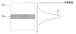
- the numerical aperture determination unit 233 determines the numerical aperture value so that the depth of focus (or depth of field) in OCT measurement is less than the thickness of the predetermined layer.
- D ⁇ / (2 ⁇ NA 2 ).
- ⁇ is the (center) wavelength of the signal light LS, which is a fixed value.
- the number of iterations can be determined based on the depth of focus D obtained as described above. For example, the iteration number determination unit 232 divides the frame height H by the focal depth D. When the quotient H / D is an integer, the quotient H / D is set as the number of iterations. When the quotient H / D is not an integer, for example, the smallest value among the integers larger than the quotient H / D is set as the number of iterations.
- the synthetic tomographic image forming unit 234 forms one synthetic tomographic image based on the two or more tomographic images obtained in this way.
- the composite tomographic image forming unit 234 includes a partial image specifying unit 2341, a position adjusting unit 2342, a partial image forming unit 2345, and a composite processing unit 2346.
- the position adjustment unit 2342 includes a feature image area specifying unit 2343 and an image position adjustment unit 2344.
- the partial image specifying unit 2341 specifies a partial image including an image area corresponding to the corresponding in-focus position for each tomographic image.
- the image area corresponding to the in-focus position indicates the depth position (z coordinate) of the frame corresponding to the in-focus position.
- the straight line FPi indicates the in-focus position when the tomographic image Gi is acquired. Pixels located on the straight line FPi form an image area corresponding to the in-focus position.
- the partial image specifying unit 2341 specifies, for example, a range Ri that extends by an equal distance in the depth direction (z direction) of the fundus oculi Ef, with the image region formed by the pixels located on the straight line FPi as the center. An image region composed of pixels located in the range Ri is a partial image of the tomographic image Gi.
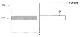
- the range Ri covers, for example, a distance obtained by dividing the frame height of the tomographic image Gi by the number of repetitions. This distance is, for example, the above-mentioned depth of focus.
- the range Ri includes a distance corresponding to “margin”.
- the position adjustment unit 2342 adjusts the relative positions of the partial images by analyzing the partial images specified by the partial image specifying unit 2341.
- the position adjustment unit 2342 includes, for example, a feature image area specifying unit 2343 and an image position adjustment unit 2344.
- the feature image region specifying unit 2343 specifies the feature image region corresponding to the feature part of the fundus oculi Ef by analyzing each partial image specified by the partial image specifying unit 2341.
- the characteristic sites are the macular region (fovea), the optic disc, and the lesion.
- An image area corresponding to a predetermined layer structure may be used as the feature image area. The process of specifying the feature image area is performed, for example, by specifying a predetermined image area in the same manner as the layer thickness calculation unit 231 and specifying the feature image area based on the shape of the image area.
- a concave portion characteristic to the macular portion is detected.
- an inclination in the depth direction (z direction) characteristic of the optic nerve head is detected.
- a convex portion characteristic to edema is detected.
- a cavity corresponding to edema can also be detected.
- the image position adjustment unit 2344 adjusts the relative positions of the plurality of partial images specified by the partial image specification unit 2341 based on the feature image region specified by the feature image region specification unit 2343.
- adjacent partial images are aligned so that the feature image areas match.
- adjacent partial images can be aligned so that the feature image regions overlap.
- the adjacent partial images can be aligned so that the feature image area is smoothly connected.
- the partial image forming unit 2345 forms a partial image by trimming a tomographic image obtained by repetitive scanning. In this trimming process, for example, pixel information (pixel position and pixel value) of pixels located in the range in the tomographic image specified by the partial image specifying unit 2341 is extracted.
- the composition processing unit 2346 composes a plurality of partial images formed by the partial image forming unit 2345 to form one tomographic image (composite tomographic image). For example, this combination processing is to convert pixel information of a plurality of partial images into single image data.
- the composite tomogram is an image in which a cross section of the fundus oculi Ef that has been repeatedly scanned is drawn. Furthermore, since each partial image includes an image region corresponding to the in-focus position at the time of OCT measurement, the combined tomographic image is an image that is in focus as a whole.
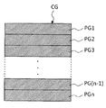
- partial images PG1 to PGn of the plurality of tomographic images G1 to Gn shown in FIG. 7A are synthesized.
- the partial images PG1 to PGn are images corresponding to the range Ri of the tomographic image Gi shown in FIG.
- the focus position is changed in stages in repetitive scanning.
- rectangular partial images PG1 to PGn can be applied.
- the composition processing unit 2346 composes these rectangular partial images PG1 to PGn to form a composite tomographic image CG shown in FIG. 7B.
- the composite tomographic image CG is obtained by arranging rectangular partial images PG1 to PGn in the depth direction (z direction).
- the composition processing unit 2346 can form a composite tomogram by combining these partial images based on the adjustment result of the relative positions of the partial images by the position adjusting unit 2342.
- the result of the position adjustment may be always reflected, or may be reflected according to circumstances.
- the image processing unit 230 that functions as described above includes, for example, the aforementioned microprocessor, RAM, ROM, hard disk drive, circuit board, and the like.
- a storage device such as a hard disk drive, a computer program for causing the microprocessor to execute the above functions is stored in advance.
- the user interface 240 includes a display unit 240A and an operation unit 240B.
- the display unit 240A includes the display device of the arithmetic control unit 200 and the display device 3 described above.
- the operation unit 240B includes the operation device of the arithmetic control unit 200 described above.
- the operation unit 240B may include various buttons and keys provided on the housing of the fundus oculi observation device 1 or outside.
- the fundus camera unit 2 has a housing similar to that of a conventional fundus camera
- the operation unit 240B may include a joystick, an operation panel, or the like provided on the housing.
- the display unit 240 ⁇ / b> A may include various display devices such as a touch panel provided on the housing of the fundus camera unit 2.
- the display unit 240A and the operation unit 240B do not need to be configured as individual devices.
- a device in which a display function and an operation function are integrated such as a touch panel
- the operation unit 240B includes the touch panel and a computer program.
- the operation content for the operation unit 240B is input to the control unit 210 as an electrical signal. Further, operations and information input may be performed using a graphical user interface (GUI) displayed on the display unit 240A and the operation unit 240B.
- GUI graphical user interface
- Examples of the scanning mode of the signal light LS by the fundus oculi observation device 1 include a horizontal scan, a vertical scan, a cross scan, a radiation scan, a circle scan, a concentric scan, and a spiral (vortex) scan. These scanning modes are selectively used as appropriate in consideration of the observation site of the fundus, the analysis target (such as retinal thickness), the time required for scanning, the precision of scanning, and the like.
- the horizontal scan is to scan the signal light LS in the horizontal direction (x direction).
- the horizontal scan also includes an aspect in which the signal light LS is scanned along a plurality of horizontal scanning lines arranged in the vertical direction (y direction). In this aspect, it is possible to arbitrarily set the scanning line interval. Further, the above-described three-dimensional image can be formed by sufficiently narrowing the interval between adjacent scanning lines (three-dimensional scanning). The same applies to the vertical scan.
- the cross scan scans the signal light LS along a cross-shaped trajectory composed of two linear trajectories (straight trajectories) orthogonal to each other.
- the signal light LS is scanned along a radial trajectory composed of a plurality of linear trajectories arranged at a predetermined angle.
- the cross scan is an example of a radiation scan.
- the circle scan scans the signal light LS along a circular locus.
- the signal light LS is scanned along a plurality of circular trajectories arranged concentrically around a predetermined center position.
- a circle scan is an example of a concentric scan.
- the signal light LS is scanned along a spiral (spiral) trajectory while gradually reducing (or increasing) the radius of rotation.
- the galvano scanner 42 is configured to scan the signal light LS in directions orthogonal to each other, the signal light LS can be scanned independently in the x direction and the y direction, respectively. Further, by simultaneously controlling the directions of the two galvanometer mirrors included in the galvano scanner 42, the signal light LS can be scanned along an arbitrary locus on the xy plane. Thereby, various scanning modes as described above can be realized.
- a tomographic image on a plane stretched by the direction along the scanning line (scanning locus) and the fundus depth direction (z direction) can be acquired.
- the above-described three-dimensional image can be acquired particularly when the scanning line interval is narrow.
- the region on the fundus oculi Ef to be scanned with the signal light LS as described above, that is, the region on the fundus oculi Ef to be subjected to OCT measurement is called a scanning region.
- the scanning area in the three-dimensional scan is a rectangular area in which a plurality of horizontal scans are arranged.
- the scanning area in the concentric scan is a disk-shaped area surrounded by the locus of the circular scan with the maximum diameter.
- the scanning area in the radial scan is a disk-shaped (or polygonal) area connecting both end positions of each scan line.
- FIG. 8 illustrates an example of the operation of the fundus oculi observation device 1. It is assumed that alignment and focus are made.
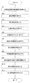
- a tomographic image for preprocessing is acquired.
- the pre-processing is processing for determining the number of scan repetitions and the numerical aperture.
- the tomographic image acquired here is, for example, a live tomographic image obtained by repeatedly scanning the same cross section of the fundus oculi Ef.
- the layer thickness calculation unit 231 analyzes the tomographic image acquired in step 1 and obtains layer thickness information indicating the thickness of the predetermined layer of the fundus oculi Ef.
- the numerical aperture determining unit 233 determines the numerical aperture value so that the depth of focus is less than the thickness indicated in the layer thickness information acquired in Step 2.
- the main control unit 211 controls the numerical aperture changing unit 40A to set the numerical aperture to the determined value.
- the repetition number determination unit 232 determines the number of repetitions in the repeated scanning of the signal light LS based on the thickness indicated in the layer thickness information acquired in Step 2. At this time, the in-focus position can also be determined. For example, the position at which the frame height of the tomographic image is equally divided by the number of iterations can be set as the in-focus position.
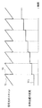
- the repetitive scan control is executed by, for example, the timing chart shown in FIG.
- the irradiation position of the signal light LS is changed according to a graph indicated by a sawtooth shape.
- the shaded portion TS in this graph indicates the scanning operation of the signal light LS for a plurality of different irradiation positions.
- the vertical portion TR of the graph shows an operation (return operation) of changing the irradiation position of the signal light LS from the last irradiation position to the first irradiation position among the plurality of irradiation positions.
- the in-focus position is changed stepwise as shown in the stepped graph TF1. The focus position is changed simultaneously with the operation of returning the irradiation position of the signal light LS (vertical portion TR).
- the image forming unit 220 forms a plurality of tomographic images based on the data obtained by repetitive scanning in Step 5.
- the number of tomographic images formed here is equal to the number of iterations determined in step 4.
- Each tomographic image is formed from data collected during one hatched portion TS in the scan timing chart shown in FIG.
- the partial image specifying unit 2341 specifies, for each tomographic image formed in Step 6, a partial image including an image region corresponding to the corresponding in-focus position.
- the feature image area specifying unit 2343 specifies the feature image area corresponding to the feature part of the fundus oculi Ef by analyzing each partial image specified in step 7.
- the image position adjustment unit 2344 adjusts the relative position of the partial image based on the feature image area specified in step 8.
- the partial image forming unit 2345 trims the partial image specified in step 7 from the tomographic image. Thereby, a partial image is formed from each tomographic image. Note that the process of step 10 can be performed at any timing after step 7.
- the composition processing unit 2346 forms a composite tomographic image of the fundus oculi Ef by synthesizing the partial images formed in step 10 based on the relative position adjustment result in step 9.
- the formed composite tomogram is stored in the storage unit 212 by the main control unit 211.
- the composite tomogram can be displayed on the display unit 240A.
- the fundus oculi observation device 1 includes an optical system, an image forming unit, a control unit, and a synthetic tomographic image forming unit.
- the optical system includes a scanning unit (galvano scanner 42) that changes the irradiation position of the signal light on the object (fundus Ef), and a focusing position changing unit (the focusing lens 43, the focusing point) that changes the focusing position of the signal light. Drive unit 43A). Further, the optical system detects interference light between the return light from the object of each signal light and the reference light. That is, the optical system performs OCT measurement of the object.
- the image forming unit 220 forms a tomographic image based on detection results of a plurality of interference lights corresponding to a plurality of signal light irradiation positions.
- the control unit main control unit 211) controls the optical system to repeatedly irradiate the plurality of irradiation positions with the signal light while changing the focus position.
- the synthetic tomographic image forming unit forms one synthetic tomographic image based on two or more tomographic images formed by the image forming unit based on the result of repetitive signal light irradiation.
- a single tomographic image (composite tomographic image) can be formed by synthesizing a plurality of tomographic images obtained by scanning the same cross section of the object a plurality of times while changing the focus position. An image in focus over the entire frame is obtained.
- OCT measurement can be performed by applying an arbitrary setting to factors (such as numerical aperture) that affect the lateral resolution. Therefore, it is possible to acquire an image with high lateral resolution and sharp overall.
- the combined tomographic image forming unit may include a partial image specifying unit (2341) for specifying a partial image including an image region corresponding to the corresponding in-focus position for each tomographic image formed by the image forming unit.
- the combined tomographic image forming unit can form a combined tomographic image by combining the specified partial images.
- the composite tomographic image forming unit may include a position adjusting unit (2342) that adjusts the relative position of these partial images by analyzing the partial images specified by the partial image specifying unit. In that case, the composite tomographic image forming unit can form a composite tomographic image by combining the partial images whose relative positions have been adjusted. By applying this configuration, even if a positional shift occurs between tomographic images due to eye movement or pulsation during repetitive scanning, it is possible to correct this positional shift and form a composite tomographic image. .
- the position adjusting unit may include a feature image region specifying unit (2343) that specifies a feature image region corresponding to a feature part of the target object by analyzing each partial image.
- the position adjustment unit (2342) can adjust the relative position of the partial image based on the identified feature image region.
- the fundus oculi observation device 1 may have a repetition number determination unit (232) that determines the number of repetitions in repetitive signal light irradiation based on the thickness of the predetermined layer of the object acquired in advance.
- a repetition number determination unit 232 that determines the number of repetitions in repetitive signal light irradiation based on the thickness of the predetermined layer of the object acquired in advance.
- the fundus oculi observation device 1 may include a layer thickness calculation unit (231) that calculates the thickness of a predetermined layer by analyzing a tomographic image acquired before repetitive signal light irradiation. By applying this configuration, it is possible to refer to the thickness of the predetermined layer obtained by actually measuring the object, so that the optimum number of iterations can be obtained.
- a layer thickness calculation unit (231) that calculates the thickness of a predetermined layer by analyzing a tomographic image acquired before repetitive signal light irradiation.
- a numerical aperture changing section (40A) for changing the numerical aperture is provided in the optical system, and a numerical aperture determining section (233) for determining the numerical aperture value so that the depth of focus is less than the thickness of the predetermined layer is provided. Also good.
- the control unit can set the numerical aperture to the determined value by controlling the numerical aperture changing unit.
- the control unit can change the in-focus position step by step for each repetition of the signal light irradiation to a plurality of irradiation positions (see FIG. 9).
- the synthetic tomographic image forming unit can form a synthetic tomographic image based on the rectangular partial image of the tomographic image including the image region corresponding to the in-focus position. This configuration provides a specific example of repetitive scanning and image composition processing.
- the composite tomographic image forming unit trims each tomographic image to form a partial image, and a composite image processing unit (2346) that forms a composite tomographic image by tiling these partial images. And may be included. Tiling refers to an image composition process that forms a single image by pasting together a plurality of images. In the tiling of this embodiment, there may or may not be a “margin”. This configuration provides a specific example of image composition processing.
- Modification 1 As described above, when eye movements, pulsations, and body movements occur during repetitive scanning, misalignment occurs in a plurality of acquired tomographic images. When this positional deviation is large, the plurality of tomographic images are images that draw different cross-sections, and are unsuitable for forming a composite tomographic image. This modification deals with such a situation.
- the optical image measurement device (fundus observation device) according to this modification has substantially the same configuration as that of the above embodiment (see FIG. 3), but is different in that a displacement detection unit 235 is provided in the image processing unit 230.
- the image processing unit 230 of this modification may include a layer thickness calculation unit 231, an iterative number determination unit 232 and / or a numerical aperture determination unit 233 similar to those in the above embodiment.
- the synthetic tomographic image forming unit 234 of this modification may have the same configuration as that of the above-described embodiment (see FIG. 4) or may have a different configuration.
- the displacement detector 235 detects the displacement between the optical system for OCT measurement and the object (fundus Ef) while performing repetitive scanning.
- This displacement detection processing includes at least one of detection of displacement in the xy direction and detection of displacement in the z direction.
- the displacement detection process is preferably executed before the process for forming the composite tomographic image.
- the displacement in the xy direction is detected by, for example, acquiring an observation image (real-time infrared fundus image) of the fundus oculi Ef in parallel with repetitive scanning, and the position of the characteristic part of the fundus oculi Ef in a frame acquired in time series. This can be done by detecting changes over time.
- the same processing can also be performed by using an observation image of the anterior segment of the eye E. Such processing is also executed in the tracking described above.
- tomographic images obtained by repetitive scanning.
- these tomographic images are time-sequential tomographic images in which the repetition frequency of repetitive scanning is used as a frame rate.
- detecting a temporal change in the form (position (x coordinate, y coordinate), shape, size, etc.) of the characteristic part of the fundus oculi Ef in the frame of these tomographic images it is possible to detect a displacement in the xy direction.
- the detection of the displacement in the z direction can be performed, for example, by analyzing a plurality of tomographic images obtained by repetitive scanning. As an example, similarly to the displacement detection in the xy direction, it is possible to detect the displacement in the z direction by detecting the temporal change of the position (z coordinate) of the characteristic part of the fundus oculi Ef in the frame of these tomographic images. is there.
- the main control unit 211 newly performs a repetitive scan of the fundus oculi Ef based on the displacement detected by the displacement detection unit 235.
- This process is, for example, a process of determining whether or not to perform a new repetitive scan based on the detected displacement (maximum displacement value or the like).
- this process may include a process of determining a new repetitive scan control content (scanning mode, scanning position, etc.) based on the detected displacement.
- the new repetitive scan is performed, for example, in the same scan mode as the previous time. Note that a scanning mode different from the previous time can also be applied. For example, when a horizontal scan is applied in the previous repetitive scan, two adjacent horizontal scans can be applied as a scan mode of a new repetitive scan to reduce the possibility of redoing again.
- the image forming unit 220 forms a plurality of new tomographic images based on the detection signal obtained by the newly executed repetitive scan.
- the synthetic tomographic image forming unit 234 forms a synthetic tomographic image based on these new tomographic images.
- Modification 2 This modification deals with the same situation as the first modification.
- a new scan is performed based on the displacement between the optical system and the object during repetitive scanning.
- notification is performed based on this displacement.
- the configuration of this modification is the same as that of Modification 1 (see FIG. 10). Similar to the first modification, the displacement detection unit 235 detects the displacement between the OCT measurement optical system and the object (fundus Ef) during repetitive scanning.
- the main control unit 211 causes the notification unit to output notification information based on the displacement detected by the displacement detection unit 235.
- Examples of the notification unit include a display unit 240A, a voice output unit (not shown), and the like.
- the notification information varies depending on the configuration of the notification unit, and is, for example, visual information (character string information, image information, etc.) or auditory information (warning message, warning sound, etc.).
- the main control unit 211 can obtain, for example, a statistical value (maximum value, standard deviation, etc.) of the detected displacement and perform notification control based on this statistical value.
- a statistical value maximum value, standard deviation, etc.
- a message indicating that can be output when the statistical value of displacement is greater than or equal to a predetermined value, a message indicating that can be output. Further, the statistical value of displacement itself can be notified. In these cases, a GUI for the user to instruct the presence or absence of remeasurement can be displayed on the display unit 240A.
- the focus position is changed stepwise in repetitive scanning (see FIG. 9), but the manner of changing the focus position is not limited to this.
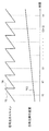
- the focus position can be continuously changed in repeated scanning. An example of a timing chart in this case is shown in FIG.
- the scanning of the signal light LS is executed in the same manner as in the above embodiment.
- the shaded portion TS in this graph indicates the scanning operation of the signal light LS for a plurality of different irradiation positions.
- the vertical portion TR indicates the returning operation of the irradiation position of the signal light LS.
- the in-focus position is continuously changed as shown in the linear graph TF2 unlike the above embodiment.
- the focus position is the same in each of the scan repetitions (that is, in each hatched portion TS), and the focus corresponding to each repetition. There is one position.
- the focus position is continuously changed. Therefore, as shown in FIG. 6 of the above-described embodiment, if the range Ri of the tomographic image Gi used for forming the composite tomographic image is rectangular, the in-focus position may deviate from the range Ri. Further, if the range Ri is widened so that the in-focus position is not deviated, the focus becomes undesirably in a portion far from the in-focus position.
- a composite tomographic image is formed using a parallelogram-shaped partial region in the tomographic image.
- An example is shown in FIG. 12A.
- a plurality of tomographic images J1 to Jn shown in FIG. 12A are formed based on data obtained by repetitive scanning executed in accordance with the timing chart shown in FIG.
- each partial image PJi of the tomographic image Ji is used for the synthesis process.
- Each partial image PJi is an image region having an equal distance in the ⁇ z direction with respect to the graph (corresponding image region) TF2 of the in-focus position in the period of the corresponding shaded portion TS. Since the graph TF2 is a monotonous straight line graph (that is, a graph having a constant inclination), each partial image PJi is an image region having a parallelogram shape.
- Each partial image PJi is an example of a parallelogram-shaped partial image.
- the synthetic tomographic image forming unit 234 forms a synthetic tomographic image by synthesizing such parallelogram-shaped partial images PJ1 to PJn.
- this composite tomographic image is an image in which partial images PJ1 to PJn having a parallelogram shape are arranged in the depth direction (z direction).
- “margin” is provided in each partial image PJi, and the synthesis is performed such that a part of the adjacent partial images PJi and Pj (i + 1) is superimposed on each other. It is also possible to perform the synthesis process without providing “margin” like the partial images PK1 to PKn of the tomographic images K1 to Kn shown in FIG. 12B.
- the tomographic image Ji including the partial image PJi closest to it that is, the image of the triangular area in the tomographic images J1 and Jn can be used. Further, by extending the graph TF2 shown in FIG. 11 back and forth over time, it is also possible to acquire images of these triangular regions separately.
- FIG. 13 shows another example when the focus position is continuously changed.
- the composition processing is performed using the rectangular partial image as in the above-described embodiment while performing the repetitive scanning by continuously changing the focus position.
- the main control unit 211 Since the main control unit 211 controls the in-focus position, the main control unit 211 recognizes the in-focus position (z coordinate) at an arbitrary timing of repeated scanning. Note that the focus position may be recognized by providing a sensor for detecting the position of the focus lens 43 during repetitive scanning.
- the main control unit 211 acquires a representative in-focus position for each shaded portion TS in the scan of the signal light LS during that period.
- This typical focus position for example, as shown in FIG. 13, focus positions at intermediate times t1 to tn during the shaded portion TS can be applied.
- the combined tomographic image forming unit 234 includes, for each tomographic image, an image region (consisting of pixels on a line segment orthogonal to the z direction) corresponding to a representative in-focus position corresponding to the hatched portion TS.
- a rectangular partial image is specified.
- the composite tomographic image forming unit 234 forms a composite tomographic image by combining the specified rectangular partial images. It is also possible to set a rectangular partial image so as to include an image region TF2 corresponding to the in-focus position shown in FIG. 12A.
- the configuration and control of the focus drive unit 43A can be simplified as compared with the case where the focus position is changed step by step.
- a composite tomographic image is formed by trimming and bonding a plurality of tomographic images, but the synthesis process is not limited to this.
- a composite tomographic image can be formed by superimposing a plurality of tomographic images using a layer function.
- the optical image measurement device (fundus observation device) according to this modification has substantially the same configuration as that of the above embodiment (see FIG. 3), but is different in that a weighting unit 2347 is provided in the image processing unit 230.
- the image processing unit 230 of this modification may include a layer thickness calculation unit 231, an iterative number determination unit 232 and / or a numerical aperture determination unit 233 similar to those in the above embodiment.
- the synthetic tomographic image forming unit 234 of this modification may have the same configuration as that of the above-described embodiment (see FIG. 4) or may have a different configuration.
- the weighting unit 2347 weights the pixels of each tomographic image to be subjected to the synthesis process. This weighting is performed, for example, by adding transparency information (alpha value) to the alpha channel of the pixel of the tomographic image.
- the weighting unit 2347 gives the transparency information so that the opacity of the pixels constituting the partial image of the above embodiment is relatively high. Specific examples thereof are shown in FIGS. 15A and 15B.
- the opacity graph ⁇ 1 shown in FIG. 15A provides transparency information to the alpha channel of the pixels of the tomographic image Mi so that the opacity of the partial image PMi of the tomographic image Mi is relatively high.
- the tomographic image Mi to which the opacity graph ⁇ 1 is applied is an image in which the opacity of the partial image PMi is high, and the opacity gradually decreases with distance from the partial image PMi.
- the opacity graph ⁇ 2 shown in FIG. 15B is created so that the opacity of the partial image PMi of the tomographic image Mi takes the maximum value and the opacity of the other parts takes the minimum value.
- the tomographic image Mi to which the opacity graph ⁇ 2 is applied is an image in which a portion other than the partial image PMi is transparent.
- the composite tomographic image forming unit 234 forms a composite tomographic image by superimposing a plurality of tomographic images M1 to Mn whose pixels are weighted by the weighting unit 2347.
- aligning a plurality of tomographic images Mi it can be performed in the same manner as in the above embodiment.
- the optical path length difference between the optical path of the signal light LS and the optical path of the reference light LR is changed by changing the position of the optical path length changing unit 41, but this optical path length difference is changed.
- the method is not limited to this.
- it is possible to change the optical path length difference by disposing a reflection mirror (reference mirror) in the optical path of the reference light and moving the reference mirror in the traveling direction of the reference light to change the optical path length of the reference light.
- the optical path length difference may be changed by moving the fundus camera unit 2 or the OCT unit 100 with respect to the eye E to change the optical path length of the signal light LS.
- the optical path length difference can be changed by moving the target in the depth direction (z direction).
- the computer program for realizing the above embodiment can be stored in an arbitrary recording medium readable by a computer.
- this recording medium for example, a semiconductor memory, an optical disk, a magneto-optical disk (CD-ROM / DVD-RAM / DVD-ROM / MO, etc.), a magnetic storage medium (hard disk / floppy (registered trademark) disk / ZIP, etc.), etc. Can be used.
- Fundus observation device 2 fundus camera unit 40A numerical aperture changing unit 41 optical path length changing unit 42 galvano scanner 43 focusing lens 43A focusing drive unit 100 OCT unit 200 arithmetic control unit 210 control unit 211 main control unit 212 storage unit 220 image forming unit 230 image processing Unit 231 layer thickness calculating unit 232 iteration number determining unit 233 numerical aperture determining unit 234 composite tomographic image forming unit 2341 partial image specifying unit 2342 position adjusting unit 2343 feature image region specifying unit 2344 image position adjusting unit 2345 partial image forming unit 2346 synthesis processing Unit 2347 weighting unit 235 displacement detection unit 240A display unit 240B operation unit E eye Ef fundus LS signal light LR reference light LC interference light
Landscapes
- Health & Medical Sciences (AREA)
- Life Sciences & Earth Sciences (AREA)
- Physics & Mathematics (AREA)
- Engineering & Computer Science (AREA)
- General Health & Medical Sciences (AREA)
- Biomedical Technology (AREA)
- Veterinary Medicine (AREA)
- Heart & Thoracic Surgery (AREA)
- Medical Informatics (AREA)
- Molecular Biology (AREA)
- Surgery (AREA)
- Animal Behavior & Ethology (AREA)
- Biophysics (AREA)
- Public Health (AREA)
- Ophthalmology & Optometry (AREA)
- General Physics & Mathematics (AREA)
- Theoretical Computer Science (AREA)
- Nuclear Medicine, Radiotherapy & Molecular Imaging (AREA)
- Radiology & Medical Imaging (AREA)
- Computer Vision & Pattern Recognition (AREA)
- Signal Processing (AREA)
- Optics & Photonics (AREA)
- Eye Examination Apparatus (AREA)
- Investigating Or Analysing Materials By Optical Means (AREA)
Abstract
Description
また、請求項2に記載の発明は、請求項1に記載の光画像計測装置であって、前記合成断層像形成部は、前記2以上の断層像のそれぞれについて、対応する合焦位置に相当する画像領域を含む部分画像を特定する部分画像特定部を含み、特定された2以上の前記部分画像を合成することにより前記合成断層像を形成することを特徴とする。
また、請求項3に記載の発明は、請求項2に記載の光画像計測装置であって、前記合成断層像形成部は、前記2以上の部分画像を解析することにより、前記2以上の部分画像の相対位置を調整する位置調整部を含み、相対位置の調整がなされた前記2以上の部分画像を合成することにより前記合成断層像を形成することを特徴とする。
また、請求項4に記載の発明は、請求項3に記載の光画像計測装置であって、前記位置調整部は、前記2以上の部分画像のそれぞれを解析することにより、対象物の特徴部位に相当する特徴画像領域を特定する特徴画像領域特定部を含み、特定された特徴画像領域に基づいて前記2以上の部分画像の相対位置を調整することを特徴とする。
また、請求項5に記載の発明は、請求項1~4のいずれか一項に記載の光画像計測装置であって、反復的な信号光の照射の間における前記光学系と対象物との変位を検出する変位検出部を有し、前記制御部は、検出された変位に基づいて、反復的な信号光の照射を新たに実行させ、前記合成断層像形成部は、新たに実行された反復的な信号光の照射の結果に基づき形成された2以上の新たな断層像に基づいて、前記合成断層像を形成することを特徴とする。
また、請求項6に記載の発明は、請求項1~4のいずれか一項に記載の光画像計測装置であって、反復的な信号光の照射の間における前記光学系と対象物との変位を検出する変位検出部を有し、前記制御部は、検出された変位に基づいて、報知部に報知情報を出力させることを特徴とする。
また、請求項7に記載の発明は、請求項1~6のいずれか一項に記載の光画像計測装置であって、予め取得された対象物の所定層の厚さに基づいて、反復的な信号光の照射における反復回数を決定する反復回数決定部を有することを特徴とする。
また、請求項8に記載の発明は、請求項7に記載の光画像計測装置であって、反復的な信号光の照射の前に取得された断層像を解析することにより、前記所定層の厚さを算出する層厚算出部を有することを特徴とする。
また、請求項9に記載の発明は、請求項7または請求項8に記載の光画像計測装置であって、前記光学系は、開口数を変更する開口数変更部を含み、焦点深度が前記所定層の厚さ未満となるように開口数の値を決定する開口数決定部を有し、前記制御部は、前記開口数変更部を制御して、開口数を決定された値に設定することを特徴とする。
また、請求項10に記載の発明は、請求項1~請求項9のいずれか一項に記載の光画像計測装置であって、前記制御部は、反復的な信号光の照射において、前記複数の照射位置に対する信号光の照射の反復ごとに前記合焦位置を段階的に変更させ、前記合成断層像形成部は、各断層像において、対応する合焦位置に相当する画像領域を含む矩形状部分画像に基づいて、前記合成断層像を形成することを特徴とする。
また、請求項11に記載の発明は、請求項1~請求項9のいずれか一項に記載の光画像計測装置であって、前記制御部は、反復的な信号光の照射において前記合焦位置を連続的に変更させ、前記合成断層像形成部は、各断層像において、対応する合焦位置に相当する画像領域を含む平行四辺形状部分画像に基づいて、前記合成断層像を形成することを特徴とする。
また、請求項12に記載の発明は、請求項1~請求項11のいずれか一項に記載の光画像計測装置であって、前記合成断層像形成部は、前記2以上の断層像のそれぞれをトリミングして部分画像を形成する部分画像形成部と、前記2以上の断層像から得られた2以上の部分画像をタイリングすることにより前記合成断層像の形成を行う合成処理部とを含むことを特徴とする。
また、請求項13に記載の発明は、請求項1~請求項11のいずれか一項に記載の光画像計測装置であって、前記合成断層像形成部は、前記2以上の断層像のそれぞれについて、当該断層像の画素に重み付けを行う重み付け部と、画素に重み付けがなされた前記2以上の断層像を重ね合わせることにより前記合成断層像の形成を行う合成処理部とを含むことを特徴とする。
図1および図2に示すように、眼底観察装置(光画像計測装置)1は、眼底カメラユニット2、OCTユニット100および演算制御ユニット200を含んで構成される。眼底カメラユニット2は、従来の眼底カメラとほぼ同様の光学系を有する。OCTユニット100には、眼底のOCT画像を取得するための光学系が設けられている。演算制御ユニット200は、各種の演算処理や制御処理等を実行するコンピュータを具備している。
図1に示す眼底カメラユニット2には、被検眼Eの眼底Efの表面形態を表す2次元画像(眼底像)を取得するための光学系が設けられている。眼底像には、観察画像や撮影画像などが含まれる。観察画像は、たとえば、近赤外光を用いて所定のフレームレートで形成されるモノクロの動画像である。撮影画像は、たとえば、可視光をフラッシュ発光して得られるカラー画像、または近赤外光若しくは可視光を照明光として用いたモノクロの静止画像であってもよい。眼底カメラユニット2は、これら以外の画像、たとえばフルオレセイン蛍光画像やインドシアニングリーン蛍光画像や自発蛍光画像などを取得可能に構成されていてもよい。
図2を参照しつつOCTユニット100の構成の一例を説明する。OCTユニット100には、眼底EfのOCT画像を取得するための光学系が設けられている。この光学系は、従来のスペクトラルドメインタイプのOCT装置と同様の構成を有する。すなわち、この光学系は、低コヒーレンス光を参照光と信号光に分割し、眼底Efを経由した信号光と参照光路を経由した参照光とを干渉させて干渉光を生成し、この干渉光のスペクトル成分を検出するように構成されている。この検出結果(検出信号)は演算制御ユニット200に送られる。
演算制御ユニット200の構成について説明する。演算制御ユニット200は、CCDイメージセンサ115から入力される検出信号を解析して眼底EfのOCT画像を形成する。そのための演算処理は、従来のスペクトラルドメインタイプのOCT装置と同様である。
眼底観察装置1の制御系の構成について図3および図4を参照しつつ説明する。
眼底観察装置1の制御系は、制御部210を中心に構成される。制御部210は、たとえば、前述のマイクロプロセッサ、RAM、ROM、ハードディスクドライブ、通信インターフェイス等を含んで構成される。制御部210には、主制御部211と記憶部212が設けられている。
主制御部211は前述の各種制御を行う。特に、主制御部211は、眼底カメラユニット2の合焦駆動部31A、開口数変更部40A、光路長変更部41、ガルバノスキャナ42、および合焦駆動部43Aを制御する。また、主制御部211は、OCTユニット100の光源ユニット101、光減衰器105および偏波調整器106を制御する。
記憶部212は、各種のデータを記憶する。記憶部212に記憶されるデータとしては、たとえば、OCT画像の画像データ、眼底像の画像データ、被検眼情報などがある。被検眼情報は、患者IDや氏名などの被検者に関する情報や、左眼/右眼の識別情報などの被検眼に関する情報を含む。また、記憶部212には、眼底観察装置1を動作させるための各種プログラムやデータが記憶されている。
画像形成部220は、CCDイメージセンサ115からの検出信号に基づいて、眼底Efの断層像の画像データを形成する。この処理には、従来のスペクトラルドメインタイプの光コヒーレンストモグラフィと同様に、ノイズ除去(ノイズ低減)、フィルタ処理、分散補償、FFT(Fast Fourier Transform)などの処理が含まれている。他のタイプのOCT装置の場合、画像形成部220は、そのタイプに応じた公知の処理を実行する。
画像処理部230は、画像形成部220により形成された画像に対して各種の画像処理や解析処理を施す。たとえば、画像処理部230は、画像の輝度補正等の各種補正処理を実行する。また、画像処理部230は、眼底カメラユニット2により得られた画像(眼底像、前眼部像等)に対して各種の画像処理や解析処理を施す。
層厚算出部231は、眼底Efの断層像を解析することにより、眼底Efの所定層の厚さを算出する。この処理は、眼底Efの所定層の境界(上端および下端)を特定する処理と、特定された上端と下端との間の距離を求める処理とを含む。
反復回数決定部232は、層厚算出部231により取得された層厚情報に基づいて、OCT計測におけるスキャンの反復回数を決定する。詳細は後述するが、この実施形態のOCT計測は、合焦位置を変更しながら眼底Efの同じ部分を反復的にスキャンするものである。反復回数決定部232により決定される反復回数は、このようなOCT計測により得られる断層像の数に相当する。また、このようなOCT計測において合焦位置を段階的に変更する場合、反復回数は、変更される合焦位置の個数に相当する。
前述のように、OCT計測における開口数は、開口数変更部40Aによって変更される。開口数決定部233は、OCT計測における焦点深度(または被写界深度)が所定層の厚さ未満となるように開口数の値を決定する。
この実施形態のOCT計測では、合焦位置を変更させつつ眼底Efの同一箇所を反復的にスキャンする。それにより、当該スキャン箇所について、合焦位置が異なる断層像が、反復回数に相当する枚数だけ得られる。合成断層像形成部234は、このようにして得られた2以上の断層像に基づいて、1枚の合成断層像を形成する。
上記のように、この実施形態では、合焦位置を変更させつつ眼底Efの同一箇所を反復的にスキャンする。よって、断層像ごとに合焦位置が異なる。部分画像特定部2341は、各断層像について、対応する合焦位置に相当する画像領域を含む部分画像を特定する。合焦位置に相当する画像領域とは、この合焦位置に対応するフレームの深さ位置(z座標)を示す。
位置調整部2342は、部分画像特定部2341により特定された部分画像を解析することにより、これら部分画像の相対位置を調整する。この処理を行うために、位置調整部2342は、たとえば特徴画像領域特定部2343および画像位置調整部2344を有する。
特徴画像領域特定部2343は、部分画像特定部2341により特定された各部分画像を解析することにより、眼底Efの特徴部位に相当する特徴画像領域を特定する。特徴部位は、黄斑部(中心窩)、視神経乳頭、病変部などである。また、所定の層組織に相当する画像領域を特徴画像領域としてもよい。特徴画像領域を特定する処理は、たとえば、層厚算出部231と同様にして所定の画像領域を特定し、この画像領域の形状に基づいて特徴画像領域を特定することにより行われる。
画像位置調整部2344は、特徴画像領域特定部2343により特定された特徴画像領域に基づいて、部分画像特定部2341により特定された複数の部分画像の相対位置を調整する。この処理は、たとえば、特徴画像領域が一致するように、隣接する部分画像の位置合わせを行うものである。「のりしろ」が設けられている場合、特徴画像領域が重なるように、隣接する部分画像の位置合わせを行うことができる。「のりしろ」が設けられていない場合、特徴画像領域がスムースにつながるように、隣接する部分画像の位置合わせを行うことができる。
部分画像形成部2345は、反復的なスキャンにより得られた断層像をトリミングして部分画像を形成する。このトリミング処理は、たとえば、部分画像特定部2341によって特定された断層像中の範囲に位置する画素の画素情報(画素位置および画素値)を抽出するものである。
合成処理部2346は、部分画像形成部2345により形成された複数の部分画像を合成して1枚の断層像(合成断層像)を形成する。この合成処理は、たとえば、複数の部分画像の画素情報を単一の画像データとするものである。合成断層像は、反復的なスキャンが行われた眼底Efの断面を描画した画像である。更に、各部分画像は、そのOCT計測時における合焦位置に相当する画像領域を含むものであるから、合成断層像は全体的にフォーカスが合った画像となる。
ユーザインターフェイス240には、表示部240Aと操作部240Bとが含まれる。表示部240Aは、前述した演算制御ユニット200の表示デバイスや表示装置3を含んで構成される。操作部240Bは、前述した演算制御ユニット200の操作デバイスを含んで構成される。操作部240Bには、眼底観察装置1の筐体や外部に設けられた各種のボタンやキーが含まれていてもよい。たとえば眼底カメラユニット2が従来の眼底カメラと同様の筺体を有する場合、操作部240Bは、この筺体に設けられたジョイスティックや操作パネル等を含んでいてもよい。また、表示部240Aは、眼底カメラユニット2の筺体に設けられたタッチパネルなどの各種表示デバイスを含んでいてもよい。
ここで、信号光LSの走査およびOCT画像について説明しておく。
眼底観察装置1の動作について説明する。図8は、眼底観察装置1の動作の一例を表す。なお、アライメントやフォーカスはなされているものとする。
まず、事前処理用の断層像を取得する。事前処理とは、スキャンの反復回数や開口数を決定する処理である。ここで取得される断層像は、たとえば、眼底Efの同一断面を繰り返しスキャンして得られるライブ断層像である。
層厚算出部231は、ステップ1で取得された断層像を解析し、眼底Efの所定層の厚さを示す層厚情報を求める。
開口数決定部233は、焦点深度が、ステップ2で取得された層厚情報に示す厚さ未満となるように、開口数の値を決定する。主制御部211は、開口数変更部40Aを制御して、開口数を決定された値に設定する。
反復回数決定部232は、ステップ2で取得された層厚情報に示す厚さに基づいて、信号光LSの反復的なスキャンにおける反復回数を決定する。このとき、合焦位置の決定も行うことが可能である。たとえば、断層像のフレーム高さを反復回数で等分する位置をそれぞれ合焦位置とすることができる。
所定のトリガを受けて、主制御部211は、合焦位置を変更させつつ反復的なスキャンを実行する。この反復的なスキャンは、ステップ3で設定された開口数で、かつ、ステップ4で決定された反復回数だけ実行される。また、変更される合焦位置の数は、反復回数と同じ数である。
画像形成部220は、ステップ5の反復的なスキャンにより得られたデータに基づいて、複数の断層像を形成する。ここで形成される断層像の個数は、ステップ4で決定された反復回数に等しい。各断層像は、図9に示すスキャンのタイミングチャートにおける一つの斜線部分TSの間に収集されたデータから形成される。
部分画像特定部2341は、ステップ6で形成された各断層像について、対応する合焦位置に相当する画像領域を含む部分画像を特定する。
特徴画像領域特定部2343は、ステップ7で特定された各部分画像を解析することにより、眼底Efの特徴部位に相当する特徴画像領域を特定する。
画像位置調整部2344は、ステップ8で特定された特徴画像領域に基づいて部分画像の相対位置を調整する。
部分画像形成部2345は、ステップ7で特定された部分画像を断層像からトリミングする。それにより、各断層像から部分画像が形成される。なお、ステップ10の処理は、ステップ7以降の任意のタイミングで行うことができる。
合成処理部2346は、ステップ9における相対位置の調整結果に基づいて、ステップ10で形成された部分画像を合成することにより、眼底Efの合成断層像を形成する。形成された合成断層像は、主制御部211により記憶部212に記憶される。また、合成断層像を表示部240Aに表示させることもできる。以上で、この動作例は終了となる。
この実施形態に係る光画像計測装置(眼底観察装置1)の作用および効果について説明する。
以上に説明した構成は、この発明を好適に実施するための一例に過ぎない。よって、この発明の要旨の範囲内における任意の変形(省略、置換、付加等)を適宜に施すことが可能である。以下、そのような変形の例を説明する。なお、上記実施形態と同様の構成部分については同じ符号を付して説明を行う。
前述のように、反復的なスキャンを行なっている間に眼球運動や拍動、体動が発生すると、取得される複数の断層像に位置ずれが発生する。この位置ずれが大きい場合、複数の断層像は異なる断面を描画する画像となり、合成断層像の形成には不適当な画像となる。この変形例は、このような事態に対処するものである。
この変形例は、変形例1と同様の事態に対処するものである。変形例1では、反復的なスキャンの間における光学系と対象物との変位に基づき新たなスキャンを行っているが、この変形例ではこの変位に基づいて報知を行う。
上記実施形態では、反復的なスキャンにおいて合焦位置を段階的に変更しているが(図9参照)、合焦位置の変更態様はこれには限定されない。たとえば、反復的なスキャンにおいて合焦位置を連続的に変更することができる。この場合のタイミングチャートの例を図11に示す。
上記実施形態では、複数の断層像をトリミングして貼り合わせることにより合成断層像を形成しているが、合成処理はこれには限定されない。たとえば、レイヤー機能を用いて複数の断層像を重ね合わせることにより合成断層像を形成することができる。
上記の実施形態においては、光路長変更部41の位置を変更することにより、信号光LSの光路と参照光LRの光路との光路長差を変更しているが、この光路長差を変更する手法はこれに限定されるものではない。たとえば、参照光の光路に反射ミラー(参照ミラー)を配置し、この参照ミラーを参照光の進行方向に移動させて参照光の光路長を変更することによって、当該光路長差を変更することが可能である。また、被検眼Eに対して眼底カメラユニット2やOCTユニット100を移動させて信号光LSの光路長を変更することにより当該光路長差を変更するようにしてもよい。また、特に対象物が生体部位でない場合などには、対象物を深度方向(z方向)に移動させることにより光路長差を変更することも可能である。
2 眼底カメラユニット
40A 開口数変更部
41 光路長変更部
42 ガルバノスキャナ
43 合焦レンズ
43A 合焦駆動部
100 OCTユニット
200 演算制御ユニット
210 制御部
211 主制御部
212 記憶部
220 画像形成部
230 画像処理部
231 層厚算出部
232 反復回数決定部
233 開口数決定部
234 合成断層像形成部
2341 部分画像特定部
2342 位置調整部
2343 特徴画像領域特定部
2344 画像位置調整部
2345 部分画像形成部
2346 合成処理部
2347 重み付け部
235 変位検出部
240A 表示部
240B 操作部
E 被検眼
Ef 眼底
LS 信号光
LR 参照光
LC 干渉光
Claims (13)
- 対象物に対する信号光の照射位置を変更する走査部と、信号光の合焦位置を変更する合焦位置変更部とを含み、各信号光の対象物からの戻り光と参照光との干渉光を検出する光学系と、
信号光の複数の照射位置に対応する複数の干渉光の検出結果に基づいて断層像を形成する画像形成部と、
前記光学系を制御することにより、前記合焦位置を変更させつつ前記複数の照射位置に対して信号光を反復的に照射させる制御部と、
反復的な信号光の照射の結果に基づき前記画像形成部により形成された2以上の断層像に基づいて、1の合成断層像を形成する合成断層像形成部と
を有する光画像計測装置。 - 前記合成断層像形成部は、
前記2以上の断層像のそれぞれについて、対応する合焦位置に相当する画像領域を含む部分画像を特定する部分画像特定部を含み、
特定された2以上の前記部分画像を合成することにより前記合成断層像を形成する
ことを特徴とする請求項1に記載の光画像計測装置。 - 前記合成断層像形成部は、
前記2以上の部分画像を解析することにより、前記2以上の部分画像の相対位置を調整する位置調整部を含み、
相対位置の調整がなされた前記2以上の部分画像を合成することにより前記合成断層像を形成する
ことを特徴とする請求項2に記載の光画像計測装置。 - 前記位置調整部は、
前記2以上の部分画像のそれぞれを解析することにより、対象物の特徴部位に相当する特徴画像領域を特定する特徴画像領域特定部を含み、
特定された特徴画像領域に基づいて前記2以上の部分画像の相対位置を調整する
ことを特徴とする請求項3に記載の光画像計測装置。 - 反復的な信号光の照射の間における前記光学系と対象物との変位を検出する変位検出部を有し、
前記制御部は、検出された変位に基づいて、反復的な信号光の照射を新たに実行させ、
前記合成断層像形成部は、新たに実行された反復的な信号光の照射の結果に基づき形成された2以上の新たな断層像に基づいて、前記合成断層像を形成する
ことを特徴とする請求項1~4のいずれか一項に記載の光画像計測装置。 - 反復的な信号光の照射の間における前記光学系と対象物との変位を検出する変位検出部を有し、
前記制御部は、検出された変位に基づいて、報知部に報知情報を出力させる
ことを特徴とする請求項1~4のいずれか一項に記載の光画像計測装置。 - 予め取得された対象物の所定層の厚さに基づいて、反復的な信号光の照射における反復回数を決定する反復回数決定部を有することを特徴とする請求項1~6のいずれか一項に記載の光画像計測装置。
- 反復的な信号光の照射の前に取得された断層像を解析することにより、前記所定層の厚さを算出する層厚算出部を有することを特徴とする請求項7に記載の光画像計測装置。
- 前記光学系は、開口数を変更する開口数変更部を含み、
焦点深度が前記所定層の厚さ未満となるように開口数の値を決定する開口数決定部を有し、
前記制御部は、前記開口数変更部を制御して、開口数を決定された値に設定する
ことを特徴とする請求項7または請求項8に記載の光画像計測装置。 - 前記制御部は、反復的な信号光の照射において、前記複数の照射位置に対する信号光の照射の反復ごとに前記合焦位置を段階的に変更させ、
前記合成断層像形成部は、各断層像において、対応する合焦位置に相当する画像領域を含む矩形状部分画像に基づいて、前記合成断層像を形成する
ことを特徴とする請求項1~請求項9のいずれか一項に記載の光画像計測装置。 - 前記制御部は、反復的な信号光の照射において前記合焦位置を連続的に変更させ、
前記合成断層像形成部は、各断層像において、対応する合焦位置に相当する画像領域を含む平行四辺形状部分画像に基づいて、前記合成断層像を形成する
ことを特徴とする請求項1~請求項9のいずれか一項に記載の光画像計測装置。 - 前記合成断層像形成部は、
前記2以上の断層像のそれぞれをトリミングして部分画像を形成する部分画像形成部と、
前記2以上の断層像から得られた2以上の部分画像をタイリングすることにより前記合成断層像の形成を行う合成処理部と
を含むことを特徴とする請求項1~請求項11のいずれか一項に記載の光画像計測装置。 - 前記合成断層像形成部は、
前記2以上の断層像のそれぞれについて、当該断層像の画素に重み付けを行う重み付け部と、
画素に重み付けがなされた前記2以上の断層像を重ね合わせることにより前記合成断層像の形成を行う合成処理部と
を含むことを特徴とする請求項1~請求項11のいずれか一項に記載の光画像計測装置。
Priority Applications (4)
| Application Number | Priority Date | Filing Date | Title |
|---|---|---|---|
| GB1510176.9A GB2523927B (en) | 2012-11-19 | 2013-10-09 | Optical coherence tomography measuring apparatus |
| DE112013005234.2T DE112013005234T5 (de) | 2012-11-19 | 2013-10-09 | Optische Bildmessvorrichtung |
| US14/441,745 US9600886B2 (en) | 2012-11-19 | 2013-10-09 | Optical image measuring apparatus |
| US15/294,921 US10102646B2 (en) | 2012-11-19 | 2016-10-17 | Optical image measuring apparatus |
Applications Claiming Priority (2)
| Application Number | Priority Date | Filing Date | Title |
|---|---|---|---|
| JP2012-253281 | 2012-11-19 | ||
| JP2012253281A JP6075755B2 (ja) | 2012-11-19 | 2012-11-19 | 光画像計測装置 |
Related Child Applications (2)
| Application Number | Title | Priority Date | Filing Date |
|---|---|---|---|
| US14/441,745 A-371-Of-International US9600886B2 (en) | 2012-11-19 | 2013-10-09 | Optical image measuring apparatus |
| US15/294,921 Division US10102646B2 (en) | 2012-11-19 | 2016-10-17 | Optical image measuring apparatus |
Publications (1)
| Publication Number | Publication Date |
|---|---|
| WO2014077057A1 true WO2014077057A1 (ja) | 2014-05-22 |
Family
ID=50730978
Family Applications (1)
| Application Number | Title | Priority Date | Filing Date |
|---|---|---|---|
| PCT/JP2013/077470 Ceased WO2014077057A1 (ja) | 2012-11-19 | 2013-10-09 | 光画像計測装置 |
Country Status (5)
| Country | Link |
|---|---|
| US (2) | US9600886B2 (ja) |
| JP (1) | JP6075755B2 (ja) |
| DE (1) | DE112013005234T5 (ja) |
| GB (1) | GB2523927B (ja) |
| WO (1) | WO2014077057A1 (ja) |
Families Citing this family (16)
| Publication number | Priority date | Publication date | Assignee | Title |
|---|---|---|---|---|
| JP6075755B2 (ja) * | 2012-11-19 | 2017-02-08 | 株式会社トプコン | 光画像計測装置 |
| US9599806B2 (en) * | 2015-06-09 | 2017-03-21 | General Electric Company | System and method for autofocusing of an imaging system |
| JP6627342B2 (ja) * | 2015-09-04 | 2020-01-08 | 株式会社ニデック | Octモーションコントラストデータ解析装置、octモーションコントラストデータ解析プログラム。 |
| JP6632267B2 (ja) * | 2015-09-04 | 2020-01-22 | キヤノン株式会社 | 眼科装置、表示制御方法およびプログラム |
| US9968416B2 (en) * | 2015-12-16 | 2018-05-15 | Novartis Ag | Ophthalmic illumination systems, devices, and methods |
| US10832051B1 (en) * | 2016-06-13 | 2020-11-10 | Facebook Technologies, Llc | Eye tracking using optical coherence methods |
| AU2017343042B2 (en) * | 2016-10-14 | 2023-05-04 | Alcon Inc. | Optical coherence tomography cross view imaging |
| US11503996B2 (en) * | 2017-05-02 | 2022-11-22 | Topcon Corporation | Ophthalmic microscope and functionality enhancement unit |
| JP2019025185A (ja) * | 2017-08-02 | 2019-02-21 | 株式会社トプコン | 眼科装置、及びデータ収集方法 |
| KR102195240B1 (ko) * | 2017-11-28 | 2020-12-24 | 주식회사 고영테크놀러지 | 기판 검사 장치 및 기판 검사 방법 |
| US10859371B2 (en) | 2017-11-28 | 2020-12-08 | Koh Young Technology Inc. | Apparatus for inspecting substrate and method thereof |
| US10852125B2 (en) | 2017-11-28 | 2020-12-01 | Koh Young Technology Inc. | Apparatus for inspecting film on substrate by using optical interference and method thereof |
| JP7187777B2 (ja) * | 2018-02-05 | 2022-12-13 | 株式会社ニデック | Oct装置、およびoct制御プログラム |
| US10963046B1 (en) | 2018-05-17 | 2021-03-30 | Facebook Technologies, Llc | Drift corrected eye tracking |
| US11949161B2 (en) | 2021-08-27 | 2024-04-02 | Eagle Technology, Llc | Systems and methods for making articles comprising a carbon nanotube material |
| US11901629B2 (en) | 2021-09-30 | 2024-02-13 | Eagle Technology, Llc | Deployable antenna reflector |
Citations (4)
| Publication number | Priority date | Publication date | Assignee | Title |
|---|---|---|---|---|
| JP2005111053A (ja) * | 2003-10-09 | 2005-04-28 | Ge Medical Systems Global Technology Co Llc | 超音波撮像装置 |
| JP2008289579A (ja) * | 2007-05-23 | 2008-12-04 | Topcon Corp | 眼底観察装置及びそれを制御するプログラム |
| JP2010279681A (ja) * | 2009-05-08 | 2010-12-16 | Canon Inc | 光画像撮像装置および光画像の撮像方法 |
| WO2011139895A1 (en) * | 2010-04-29 | 2011-11-10 | Massachusetts Institute Of Technology | Method and apparatus for motion correction and image enhancement for optical coherence tomography |
Family Cites Families (17)
| Publication number | Priority date | Publication date | Assignee | Title |
|---|---|---|---|---|
| DE19814057B4 (de) | 1998-03-30 | 2009-01-02 | Carl Zeiss Meditec Ag | Anordnung zur optischen Kohärenztomographie und Kohärenztopographie |
| JP4804820B2 (ja) | 2005-07-15 | 2011-11-02 | サンテック株式会社 | 光断層画像表示システム |
| JP2007101250A (ja) | 2005-09-30 | 2007-04-19 | Fujifilm Corp | 光断層画像化方法 |
| JP5095167B2 (ja) | 2006-09-19 | 2012-12-12 | 株式会社トプコン | 眼底観察装置、眼底画像表示装置及び眼底観察プログラム |
| DE102006053118B4 (de) | 2006-11-10 | 2022-02-17 | Carl Zeiss Meditec Ag | Planungseinrichtung zum Vorbereiten von Steuerdaten für eine Behandlungsvorrichtung zur operativen Fehlsichtigkeitskorrektur, Behandlungsvorrichtung zur operativen Fehlsichtigkeitskorrektur und Verfahren zum Vorbereiten von Steuerdaten dafür |
| JP5448353B2 (ja) | 2007-05-02 | 2014-03-19 | キヤノン株式会社 | 光干渉断層計を用いた画像形成方法、及び光干渉断層装置 |
| JP5479047B2 (ja) | 2008-12-26 | 2014-04-23 | キヤノン株式会社 | 撮像装置および撮像方法 |
| JP5415812B2 (ja) | 2009-04-17 | 2014-02-12 | 株式会社トプコン | 光画像計測装置及びその制御方法 |
| JP5298352B2 (ja) | 2009-09-16 | 2013-09-25 | 株式会社トプコン | 光構造像観察装置及び内視鏡装置 |
| JP5543171B2 (ja) | 2009-10-27 | 2014-07-09 | 株式会社トプコン | 光画像計測装置 |
| JP5511324B2 (ja) | 2009-11-17 | 2014-06-04 | キヤノン株式会社 | 補償光学装置、補償光学方法、撮像装置、撮像方法 |
| US8366271B2 (en) | 2010-01-20 | 2013-02-05 | Duke University | Systems and methods for surgical microscope and optical coherence tomography (OCT) imaging |
| JP2012021794A (ja) * | 2010-07-12 | 2012-02-02 | Canon Inc | 光干渉計測データ読出方法、光干渉断層診断装置および光干渉断層診断システム |
| US9033510B2 (en) | 2011-03-30 | 2015-05-19 | Carl Zeiss Meditec, Inc. | Systems and methods for efficiently obtaining measurements of the human eye using tracking |
| JP5383735B2 (ja) | 2011-03-31 | 2014-01-08 | キヤノン株式会社 | 光干渉断層撮影装置、画像処理装置、画像処理方法、及びプログラム |
| JP5639523B2 (ja) * | 2011-03-31 | 2014-12-10 | キヤノン株式会社 | 光干渉断層撮影装置、光干渉断層撮影装置の制御方法、プログラムおよび眼科システム |
| JP6075755B2 (ja) * | 2012-11-19 | 2017-02-08 | 株式会社トプコン | 光画像計測装置 |
-
2012
- 2012-11-19 JP JP2012253281A patent/JP6075755B2/ja active Active
-
2013
- 2013-10-09 GB GB1510176.9A patent/GB2523927B/en active Active
- 2013-10-09 DE DE112013005234.2T patent/DE112013005234T5/de active Granted
- 2013-10-09 WO PCT/JP2013/077470 patent/WO2014077057A1/ja not_active Ceased
- 2013-10-09 US US14/441,745 patent/US9600886B2/en active Active
-
2016
- 2016-10-17 US US15/294,921 patent/US10102646B2/en active Active
Patent Citations (4)
| Publication number | Priority date | Publication date | Assignee | Title |
|---|---|---|---|---|
| JP2005111053A (ja) * | 2003-10-09 | 2005-04-28 | Ge Medical Systems Global Technology Co Llc | 超音波撮像装置 |
| JP2008289579A (ja) * | 2007-05-23 | 2008-12-04 | Topcon Corp | 眼底観察装置及びそれを制御するプログラム |
| JP2010279681A (ja) * | 2009-05-08 | 2010-12-16 | Canon Inc | 光画像撮像装置および光画像の撮像方法 |
| WO2011139895A1 (en) * | 2010-04-29 | 2011-11-10 | Massachusetts Institute Of Technology | Method and apparatus for motion correction and image enhancement for optical coherence tomography |
Also Published As
| Publication number | Publication date |
|---|---|
| GB201510176D0 (en) | 2015-07-29 |
| JP2014100230A (ja) | 2014-06-05 |
| DE112013005234T5 (de) | 2015-08-06 |
| GB2523927A (en) | 2015-09-09 |
| US10102646B2 (en) | 2018-10-16 |
| JP6075755B2 (ja) | 2017-02-08 |
| US20150294468A1 (en) | 2015-10-15 |
| US20170027439A1 (en) | 2017-02-02 |
| US9600886B2 (en) | 2017-03-21 |
| GB2523927B (en) | 2018-12-26 |
Similar Documents
| Publication | Publication Date | Title |
|---|---|---|
| JP6075755B2 (ja) | 光画像計測装置 | |
| JP5867719B2 (ja) | 光画像計測装置 | |
| JP5912358B2 (ja) | 眼底観察装置 | |
| JP6045895B2 (ja) | 眼科観察装置 | |
| JP5628636B2 (ja) | 眼底画像処理装置及び眼底観察装置 | |
| JP5916110B2 (ja) | 画像表示装置、画像表示方法、及びプログラム | |
| JP5415902B2 (ja) | 眼科観察装置 | |
| JP5936254B2 (ja) | 眼底観察装置及び眼底画像解析装置 | |
| JP5543171B2 (ja) | 光画像計測装置 | |
| JP5937163B2 (ja) | 眼底解析装置及び眼底観察装置 | |
| JP5941761B2 (ja) | 眼科撮影装置及び眼科画像処理装置 | |
| US10058242B2 (en) | Ophthalmologic imaging apparatus and ophthalmologic image display apparatus | |
| JP6411728B2 (ja) | 眼科観察装置 | |
| JP6165935B2 (ja) | 光画像計測装置 | |
| JPWO2020044712A1 (ja) | 眼科装置、及びその制御方法 | |
| JP6452977B2 (ja) | 眼科撮影装置及びその制御方法 | |
| JP6159454B2 (ja) | 眼科観察装置 | |
| JP6021289B2 (ja) | 血流情報生成装置、血流情報生成方法、及びプログラム | |
| JP6158535B2 (ja) | 眼底解析装置 | |
| JP6503040B2 (ja) | 眼科観察装置 | |
| JP2016104306A (ja) | 眼科撮影装置 | |
| JP6404431B2 (ja) | 眼科観察装置 | |
| WO2016039188A1 (ja) | 眼底解析装置及び眼底観察装置 | |
| JP2016104305A (ja) | 眼科撮影装置 |
Legal Events
| Date | Code | Title | Description |
|---|---|---|---|
| 121 | Ep: the epo has been informed by wipo that ep was designated in this application |
Ref document number: 13855548 Country of ref document: EP Kind code of ref document: A1 |
|
| WWE | Wipo information: entry into national phase |
Ref document number: 14441745 Country of ref document: US |
|
| WWE | Wipo information: entry into national phase |
Ref document number: 1120130052342 Country of ref document: DE Ref document number: 112013005234 Country of ref document: DE |
|
| ENP | Entry into the national phase |
Ref document number: 1510176 Country of ref document: GB Kind code of ref document: A Free format text: PCT FILING DATE = 20131009 |
|
| WWE | Wipo information: entry into national phase |
Ref document number: 1510176.9 Country of ref document: GB |
|
| 122 | Ep: pct application non-entry in european phase |
Ref document number: 13855548 Country of ref document: EP Kind code of ref document: A1 |