WO2014073632A1 - 電源装置 - Google Patents
電源装置 Download PDFInfo
- Publication number
- WO2014073632A1 WO2014073632A1 PCT/JP2013/080191 JP2013080191W WO2014073632A1 WO 2014073632 A1 WO2014073632 A1 WO 2014073632A1 JP 2013080191 W JP2013080191 W JP 2013080191W WO 2014073632 A1 WO2014073632 A1 WO 2014073632A1
- Authority
- WO
- WIPO (PCT)
- Prior art keywords
- power supply
- state
- inverter
- power
- power source
- Prior art date
Links
Images


Classifications
-
- B—PERFORMING OPERATIONS; TRANSPORTING
- B60—VEHICLES IN GENERAL
- B60L—PROPULSION OF ELECTRICALLY-PROPELLED VEHICLES; SUPPLYING ELECTRIC POWER FOR AUXILIARY EQUIPMENT OF ELECTRICALLY-PROPELLED VEHICLES; ELECTRODYNAMIC BRAKE SYSTEMS FOR VEHICLES IN GENERAL; MAGNETIC SUSPENSION OR LEVITATION FOR VEHICLES; MONITORING OPERATING VARIABLES OF ELECTRICALLY-PROPELLED VEHICLES; ELECTRIC SAFETY DEVICES FOR ELECTRICALLY-PROPELLED VEHICLES
- B60L7/00—Electrodynamic brake systems for vehicles in general
- B60L7/10—Dynamic electric regenerative braking
- B60L7/14—Dynamic electric regenerative braking for vehicles propelled by ac motors
-
- H—ELECTRICITY
- H02—GENERATION; CONVERSION OR DISTRIBUTION OF ELECTRIC POWER
- H02P—CONTROL OR REGULATION OF ELECTRIC MOTORS, ELECTRIC GENERATORS OR DYNAMO-ELECTRIC CONVERTERS; CONTROLLING TRANSFORMERS, REACTORS OR CHOKE COILS
- H02P23/00—Arrangements or methods for the control of AC motors characterised by a control method other than vector control
-
- B—PERFORMING OPERATIONS; TRANSPORTING
- B60—VEHICLES IN GENERAL
- B60L—PROPULSION OF ELECTRICALLY-PROPELLED VEHICLES; SUPPLYING ELECTRIC POWER FOR AUXILIARY EQUIPMENT OF ELECTRICALLY-PROPELLED VEHICLES; ELECTRODYNAMIC BRAKE SYSTEMS FOR VEHICLES IN GENERAL; MAGNETIC SUSPENSION OR LEVITATION FOR VEHICLES; MONITORING OPERATING VARIABLES OF ELECTRICALLY-PROPELLED VEHICLES; ELECTRIC SAFETY DEVICES FOR ELECTRICALLY-PROPELLED VEHICLES
- B60L50/00—Electric propulsion with power supplied within the vehicle
- B60L50/50—Electric propulsion with power supplied within the vehicle using propulsion power supplied by batteries or fuel cells
- B60L50/51—Electric propulsion with power supplied within the vehicle using propulsion power supplied by batteries or fuel cells characterised by AC-motors
-
- B—PERFORMING OPERATIONS; TRANSPORTING
- B60—VEHICLES IN GENERAL
- B60L—PROPULSION OF ELECTRICALLY-PROPELLED VEHICLES; SUPPLYING ELECTRIC POWER FOR AUXILIARY EQUIPMENT OF ELECTRICALLY-PROPELLED VEHICLES; ELECTRODYNAMIC BRAKE SYSTEMS FOR VEHICLES IN GENERAL; MAGNETIC SUSPENSION OR LEVITATION FOR VEHICLES; MONITORING OPERATING VARIABLES OF ELECTRICALLY-PROPELLED VEHICLES; ELECTRIC SAFETY DEVICES FOR ELECTRICALLY-PROPELLED VEHICLES
- B60L58/00—Methods or circuit arrangements for monitoring or controlling batteries or fuel cells, specially adapted for electric vehicles
- B60L58/10—Methods or circuit arrangements for monitoring or controlling batteries or fuel cells, specially adapted for electric vehicles for monitoring or controlling batteries
- B60L58/18—Methods or circuit arrangements for monitoring or controlling batteries or fuel cells, specially adapted for electric vehicles for monitoring or controlling batteries of two or more battery modules
- B60L58/19—Switching between serial connection and parallel connection of battery modules
-
- H—ELECTRICITY
- H02—GENERATION; CONVERSION OR DISTRIBUTION OF ELECTRIC POWER
- H02J—CIRCUIT ARRANGEMENTS OR SYSTEMS FOR SUPPLYING OR DISTRIBUTING ELECTRIC POWER; SYSTEMS FOR STORING ELECTRIC ENERGY
- H02J7/00—Circuit arrangements for charging or depolarising batteries or for supplying loads from batteries
- H02J7/0013—Circuit arrangements for charging or depolarising batteries or for supplying loads from batteries acting upon several batteries simultaneously or sequentially
- H02J7/0024—Parallel/serial switching of connection of batteries to charge or load circuit
-
- H—ELECTRICITY
- H02—GENERATION; CONVERSION OR DISTRIBUTION OF ELECTRIC POWER
- H02P—CONTROL OR REGULATION OF ELECTRIC MOTORS, ELECTRIC GENERATORS OR DYNAMO-ELECTRIC CONVERTERS; CONTROLLING TRANSFORMERS, REACTORS OR CHOKE COILS
- H02P27/00—Arrangements or methods for the control of AC motors characterised by the kind of supply voltage
- H02P27/04—Arrangements or methods for the control of AC motors characterised by the kind of supply voltage using variable-frequency supply voltage, e.g. inverter or converter supply voltage
- H02P27/06—Arrangements or methods for the control of AC motors characterised by the kind of supply voltage using variable-frequency supply voltage, e.g. inverter or converter supply voltage using dc to ac converters or inverters
-
- H—ELECTRICITY
- H02—GENERATION; CONVERSION OR DISTRIBUTION OF ELECTRIC POWER
- H02P—CONTROL OR REGULATION OF ELECTRIC MOTORS, ELECTRIC GENERATORS OR DYNAMO-ELECTRIC CONVERTERS; CONTROLLING TRANSFORMERS, REACTORS OR CHOKE COILS
- H02P5/00—Arrangements specially adapted for regulating or controlling the speed or torque of two or more electric motors
- H02P5/74—Arrangements specially adapted for regulating or controlling the speed or torque of two or more electric motors controlling two or more ac dynamo-electric motors
-
- B—PERFORMING OPERATIONS; TRANSPORTING
- B60—VEHICLES IN GENERAL
- B60L—PROPULSION OF ELECTRICALLY-PROPELLED VEHICLES; SUPPLYING ELECTRIC POWER FOR AUXILIARY EQUIPMENT OF ELECTRICALLY-PROPELLED VEHICLES; ELECTRODYNAMIC BRAKE SYSTEMS FOR VEHICLES IN GENERAL; MAGNETIC SUSPENSION OR LEVITATION FOR VEHICLES; MONITORING OPERATING VARIABLES OF ELECTRICALLY-PROPELLED VEHICLES; ELECTRIC SAFETY DEVICES FOR ELECTRICALLY-PROPELLED VEHICLES
- B60L2210/00—Converter types
- B60L2210/30—AC to DC converters
-
- B—PERFORMING OPERATIONS; TRANSPORTING
- B60—VEHICLES IN GENERAL
- B60L—PROPULSION OF ELECTRICALLY-PROPELLED VEHICLES; SUPPLYING ELECTRIC POWER FOR AUXILIARY EQUIPMENT OF ELECTRICALLY-PROPELLED VEHICLES; ELECTRODYNAMIC BRAKE SYSTEMS FOR VEHICLES IN GENERAL; MAGNETIC SUSPENSION OR LEVITATION FOR VEHICLES; MONITORING OPERATING VARIABLES OF ELECTRICALLY-PROPELLED VEHICLES; ELECTRIC SAFETY DEVICES FOR ELECTRICALLY-PROPELLED VEHICLES
- B60L2210/00—Converter types
- B60L2210/40—DC to AC converters
- B60L2210/42—Voltage source inverters
-
- B—PERFORMING OPERATIONS; TRANSPORTING
- B60—VEHICLES IN GENERAL
- B60L—PROPULSION OF ELECTRICALLY-PROPELLED VEHICLES; SUPPLYING ELECTRIC POWER FOR AUXILIARY EQUIPMENT OF ELECTRICALLY-PROPELLED VEHICLES; ELECTRODYNAMIC BRAKE SYSTEMS FOR VEHICLES IN GENERAL; MAGNETIC SUSPENSION OR LEVITATION FOR VEHICLES; MONITORING OPERATING VARIABLES OF ELECTRICALLY-PROPELLED VEHICLES; ELECTRIC SAFETY DEVICES FOR ELECTRICALLY-PROPELLED VEHICLES
- B60L2220/00—Electrical machine types; Structures or applications thereof
- B60L2220/40—Electrical machine applications
- B60L2220/42—Electrical machine applications with use of more than one motor
-
- B—PERFORMING OPERATIONS; TRANSPORTING
- B60—VEHICLES IN GENERAL
- B60L—PROPULSION OF ELECTRICALLY-PROPELLED VEHICLES; SUPPLYING ELECTRIC POWER FOR AUXILIARY EQUIPMENT OF ELECTRICALLY-PROPELLED VEHICLES; ELECTRODYNAMIC BRAKE SYSTEMS FOR VEHICLES IN GENERAL; MAGNETIC SUSPENSION OR LEVITATION FOR VEHICLES; MONITORING OPERATING VARIABLES OF ELECTRICALLY-PROPELLED VEHICLES; ELECTRIC SAFETY DEVICES FOR ELECTRICALLY-PROPELLED VEHICLES
- B60L2240/00—Control parameters of input or output; Target parameters
- B60L2240/40—Drive Train control parameters
- B60L2240/42—Drive Train control parameters related to electric machines
- B60L2240/423—Torque
-
- B—PERFORMING OPERATIONS; TRANSPORTING
- B60—VEHICLES IN GENERAL
- B60L—PROPULSION OF ELECTRICALLY-PROPELLED VEHICLES; SUPPLYING ELECTRIC POWER FOR AUXILIARY EQUIPMENT OF ELECTRICALLY-PROPELLED VEHICLES; ELECTRODYNAMIC BRAKE SYSTEMS FOR VEHICLES IN GENERAL; MAGNETIC SUSPENSION OR LEVITATION FOR VEHICLES; MONITORING OPERATING VARIABLES OF ELECTRICALLY-PROPELLED VEHICLES; ELECTRIC SAFETY DEVICES FOR ELECTRICALLY-PROPELLED VEHICLES
- B60L2240/00—Control parameters of input or output; Target parameters
- B60L2240/40—Drive Train control parameters
- B60L2240/52—Drive Train control parameters related to converters
- B60L2240/526—Operating parameters
-
- B—PERFORMING OPERATIONS; TRANSPORTING
- B60—VEHICLES IN GENERAL
- B60L—PROPULSION OF ELECTRICALLY-PROPELLED VEHICLES; SUPPLYING ELECTRIC POWER FOR AUXILIARY EQUIPMENT OF ELECTRICALLY-PROPELLED VEHICLES; ELECTRODYNAMIC BRAKE SYSTEMS FOR VEHICLES IN GENERAL; MAGNETIC SUSPENSION OR LEVITATION FOR VEHICLES; MONITORING OPERATING VARIABLES OF ELECTRICALLY-PROPELLED VEHICLES; ELECTRIC SAFETY DEVICES FOR ELECTRICALLY-PROPELLED VEHICLES
- B60L2240/00—Control parameters of input or output; Target parameters
- B60L2240/40—Drive Train control parameters
- B60L2240/52—Drive Train control parameters related to converters
- B60L2240/527—Voltage
-
- B—PERFORMING OPERATIONS; TRANSPORTING
- B60—VEHICLES IN GENERAL
- B60L—PROPULSION OF ELECTRICALLY-PROPELLED VEHICLES; SUPPLYING ELECTRIC POWER FOR AUXILIARY EQUIPMENT OF ELECTRICALLY-PROPELLED VEHICLES; ELECTRODYNAMIC BRAKE SYSTEMS FOR VEHICLES IN GENERAL; MAGNETIC SUSPENSION OR LEVITATION FOR VEHICLES; MONITORING OPERATING VARIABLES OF ELECTRICALLY-PROPELLED VEHICLES; ELECTRIC SAFETY DEVICES FOR ELECTRICALLY-PROPELLED VEHICLES
- B60L2240/00—Control parameters of input or output; Target parameters
- B60L2240/40—Drive Train control parameters
- B60L2240/52—Drive Train control parameters related to converters
- B60L2240/529—Current
-
- B—PERFORMING OPERATIONS; TRANSPORTING
- B60—VEHICLES IN GENERAL
- B60L—PROPULSION OF ELECTRICALLY-PROPELLED VEHICLES; SUPPLYING ELECTRIC POWER FOR AUXILIARY EQUIPMENT OF ELECTRICALLY-PROPELLED VEHICLES; ELECTRODYNAMIC BRAKE SYSTEMS FOR VEHICLES IN GENERAL; MAGNETIC SUSPENSION OR LEVITATION FOR VEHICLES; MONITORING OPERATING VARIABLES OF ELECTRICALLY-PROPELLED VEHICLES; ELECTRIC SAFETY DEVICES FOR ELECTRICALLY-PROPELLED VEHICLES
- B60L2240/00—Control parameters of input or output; Target parameters
- B60L2240/40—Drive Train control parameters
- B60L2240/54—Drive Train control parameters related to batteries
- B60L2240/547—Voltage
-
- H—ELECTRICITY
- H02—GENERATION; CONVERSION OR DISTRIBUTION OF ELECTRIC POWER
- H02J—CIRCUIT ARRANGEMENTS OR SYSTEMS FOR SUPPLYING OR DISTRIBUTING ELECTRIC POWER; SYSTEMS FOR STORING ELECTRIC ENERGY
- H02J2310/00—The network for supplying or distributing electric power characterised by its spatial reach or by the load
- H02J2310/40—The network being an on-board power network, i.e. within a vehicle
- H02J2310/48—The network being an on-board power network, i.e. within a vehicle for electric vehicles [EV] or hybrid vehicles [HEV]
-
- Y—GENERAL TAGGING OF NEW TECHNOLOGICAL DEVELOPMENTS; GENERAL TAGGING OF CROSS-SECTIONAL TECHNOLOGIES SPANNING OVER SEVERAL SECTIONS OF THE IPC; TECHNICAL SUBJECTS COVERED BY FORMER USPC CROSS-REFERENCE ART COLLECTIONS [XRACs] AND DIGESTS
- Y02—TECHNOLOGIES OR APPLICATIONS FOR MITIGATION OR ADAPTATION AGAINST CLIMATE CHANGE
- Y02T—CLIMATE CHANGE MITIGATION TECHNOLOGIES RELATED TO TRANSPORTATION
- Y02T10/00—Road transport of goods or passengers
- Y02T10/60—Other road transportation technologies with climate change mitigation effect
- Y02T10/64—Electric machine technologies in electromobility
-
- Y—GENERAL TAGGING OF NEW TECHNOLOGICAL DEVELOPMENTS; GENERAL TAGGING OF CROSS-SECTIONAL TECHNOLOGIES SPANNING OVER SEVERAL SECTIONS OF THE IPC; TECHNICAL SUBJECTS COVERED BY FORMER USPC CROSS-REFERENCE ART COLLECTIONS [XRACs] AND DIGESTS
- Y02—TECHNOLOGIES OR APPLICATIONS FOR MITIGATION OR ADAPTATION AGAINST CLIMATE CHANGE
- Y02T—CLIMATE CHANGE MITIGATION TECHNOLOGIES RELATED TO TRANSPORTATION
- Y02T10/00—Road transport of goods or passengers
- Y02T10/60—Other road transportation technologies with climate change mitigation effect
- Y02T10/70—Energy storage systems for electromobility, e.g. batteries
-
- Y—GENERAL TAGGING OF NEW TECHNOLOGICAL DEVELOPMENTS; GENERAL TAGGING OF CROSS-SECTIONAL TECHNOLOGIES SPANNING OVER SEVERAL SECTIONS OF THE IPC; TECHNICAL SUBJECTS COVERED BY FORMER USPC CROSS-REFERENCE ART COLLECTIONS [XRACs] AND DIGESTS
- Y02—TECHNOLOGIES OR APPLICATIONS FOR MITIGATION OR ADAPTATION AGAINST CLIMATE CHANGE
- Y02T—CLIMATE CHANGE MITIGATION TECHNOLOGIES RELATED TO TRANSPORTATION
- Y02T10/00—Road transport of goods or passengers
- Y02T10/60—Other road transportation technologies with climate change mitigation effect
- Y02T10/72—Electric energy management in electromobility
Definitions
- the present invention relates to a power supply device.
- an object of the present invention is to provide a power supply device that reduces voltage fluctuation at the time of switching between the power supply parallel state / power supply serial state of the first power supply and the second power supply with a simple configuration.
- the present invention provides a power source body having a first power source and a second power source, a power source parallel state of the first power source and the second power source, a power source serial state, and the second power source.
- a first connection state in which the power supply state switching means for switching to the single second power supply state in which only the power supply is output, the inverter connected to the motor generator, and the power supply main body in the power supply parallel state or the power supply series state and the inverter are connected.
- an inverter connection state switching means for switching to a second connection state in which the power source body in the single second power state and the inverter are connected in series, wherein the power state switching means changes from a power supply parallel state to a power supply series state.
- the inverter connection state switching means switches to the first connection state, and the inverter operates with the motor generator as a motor.
- the power supply state switching means switches to the single second power supply state
- the inverter connection state switch means switches to the second connection state, and the second power supply and the inverter serving as a power supply by the motor generator operating as a generator;
- the power supply state switching means switches to the power supply series state.
- the inverter connection state switching unit switches to the first connection state, and the inverter operates the motor generator as a motor.
- the power supply state switching means switches to the single second power supply state
- the inverter connection state switch means switches to the second connection state, and after passing through the series connection state between the second power supply and the inverter that temporarily becomes the power supply,
- the state switching means switches to the power supply series state.
- the present invention provides a power source body having a first power source and a second power source, a power source parallel state of the first power source and the second power source, a power source serial state, and the second power source.
- a first connection state in which the power supply state switching means for switching to the single second power supply state in which only the power supply is output, the inverter connected to the motor generator, and the power supply main body in the power supply parallel state or the power supply series state and the inverter are connected.
- an inverter connection state switching means for switching to a second connection state in which the power source body in the single second power state and the inverter are connected in series, wherein the power state switching means changes from a power supply series state to a power supply parallel state.
- the inverter connection state switching means switches to the first connection state, and the inverter operates with the motor generator as a motor.
- the power supply state switching means switches to the single second power supply state
- the inverter connection state switch means switches to the second connection state, and the second power supply and the inverter serving as a power supply by the motor generator operating as a generator;
- the power supply state switching means switches to the power supply parallel state.
- the inverter connection state switching unit switches to the first connection state, and the inverter operates the motor generator as a motor.
- the power supply state switching means switches to the single second power supply state
- the inverter connection state switch means switches to the second connection state, and after passing through the series connection state between the second power supply and the inverter that temporarily becomes the power supply,
- the state switching means switches to the power supply series state.
- the first power source includes a first power source positive terminal and a first power source negative terminal
- the second power source includes a second power source positive terminal and a second power source negative terminal
- the inverter includes an inverter positive terminal and an inverter negative terminal; a positive bus connected to the second power positive terminal; a negative bus connected to the first power negative terminal and the inverter negative terminal;
- a first switch for turning on / off the connection between the first power supply positive terminal and the positive bus; a second switch for turning on / off the connection between the first power supply positive terminal and the second power supply negative terminal;
- a third switch for turning on / off the connection between the positive bus and the inverter positive terminal, a fourth switch for turning on / off the connection between the second power source negative terminal and the inverter positive terminal, and the second
- a fifth switch for ON / OFF the connection between the negative electrode bus the source negative terminal is preferably provided.
- the present invention provides a power source body having a first power source and a second power source, a power source parallel state of the first power source and the second power source, a power source serial state, and the second power source.
- the present invention provides a power source body having a first power source and a second power source, a power source parallel state of the first power source and the second power source, a power source serial state, and the second power source.
- the generator when the power source control means rotates the rotor, the generator operates (power generation), and the inverter is a power source by the operating generator.
- the present invention it is possible to provide a power supply apparatus that reduces voltage fluctuations when switching between the power supply parallel state / power supply serial state of the first power supply and the second power supply with a simple configuration.
- the power supply device 1 is mounted on a series-type hybrid vehicle (electric vehicle) (not shown), and is a device that transfers power between the first motor generator 110 and the second motor generator 120.
- the first motor generator 110 is connected to an internal combustion engine (power source) (not shown) so as to exchange power with the internal combustion engine.
- the second motor generator 120 is connected to drive wheels (not shown), and exchanges power with the drive wheels.
- the first motor generator 110 has a function of a motor (electric motor) and a function of a generator (generator). That is, since the first motor generator 110 is arranged on the internal combustion engine side, it functions as a generator mainly by power from the internal combustion engine, but temporarily when the power supply main body 40 is switched between the power supply parallel state and the power supply serial state. It is configured to function as a motor.
- the first motor generator 110 includes a columnar first rotor that rotates integrally with a crankshaft (output shaft) of the internal combustion engine, and a cylindrical first stator that surrounds the first rotor.
- the first stator includes a cylindrical first stator main body and first stator coils 111, 112, and 113 attached to the first teeth of the first stator main body.
- the first stator coils 111, 112, and 113 are coils corresponding to the U phase, the V phase, and the W phase.
- the cylindrical first rotor may rotate via a crankshaft of the internal combustion engine and a fastening device (connecting / disconnecting device) such as a clutch.
- An internal combustion engine is, for example, a reciprocating type, and is a power generation device that generates power (rotational force) by rotating a crankshaft by burning fuel.
- the internal combustion engine is a mixture of an intake valve that intakes a mixed gas of fuel and air, an exhaust valve that exhausts exhaust gas after combustion, an injector that injects fuel, and a throttle valve that controls the flow rate of the intake air An ignition plug for igniting the gas.
- the ECU 90 appropriately controls the intake valve, the exhaust valve, the injector, the throttle valve, and the spark plug so that the output of the internal combustion engine (crankshaft rotation speed, torque) is controlled.
- the second motor generator 120 has a function of a motor (electric motor) and a function of a generator (generator). That is, the second motor generator 120 (1) functions as a motor during power running, generates driving force by consuming AC power (three-phase AC power) from the second inverter 20, and (2) during regeneration. It functions as a generator and generates AC power by the rotational force of the wheels.
- the second motor generator 120 includes a columnar second rotor that rotates integrally with the drive wheel, and a cylindrical second stator that surrounds the second rotor.
- the second stator includes a cylindrical second stator body and second stator coils 121, 122, 123 attached to the second teeth of the second stator body.
- the second stator coils 121, 122, and 123 are coils corresponding to the U phase, the V phase, and the W phase.
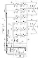
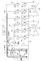
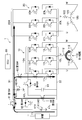
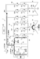
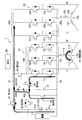
- the power supply device 1 includes a first inverter 10 on the internal combustion engine side, a second inverter 20 on the drive wheel side, a positive bus 31 and a negative bus 32, a power source body 40, a capacitor 51, and first switches 61 to 5.
- a switch 65, an auxiliary machine 71, and an ECU 90 are provided.
- the first inverter 10 is a device that exchanges power with the first motor generator 110 on the internal combustion engine side. Specifically, the first inverter 10 converts (1) AC power from the first motor generator 110 into DC power during power generation (including inertial rotation of the first rotor), and supplies the power source body 40 or the second It mainly has a function of outputting to the inverter 20. In addition, the first inverter 10 also has a function of converting DC power from the first secondary battery 41 and the like into AC power and outputting the AC power to the first motor generator 110 to temporarily use the first motor generator 110 as a motor. I have.
- the first inverter 10 includes a first inverter positive terminal 10H (high voltage side terminal) and a first inverter negative terminal 10L (low voltage side terminal).
- the first inverter 10 includes a U-phase switch 11H (transistor such as IGBT (Insulated Gate Bipolar Transistor)) and a switch 11L, a V-phase switch 12H and a switch 12L, a W-phase switch 13H and a switch 13L, It is equipped with.
- each switch 11H is provided with a diode that is in parallel with each switch 11H and the like and allows energization from the negative electrode side to the positive electrode side.
- the collector of the switch 11H is connected to the first inverter positive terminal 10H
- the emitter of the switch 11H is connected to the collector of the switch 11L
- the emitter of the switch 11L is connected to the first inverter negative terminal 10L.
- the emitter of the switch 11H and the collector of the switch 11L are connected to the first stator coil 111 corresponding to the U phase. Since the V phase and the W phase are in the same connection state as the U phase, description thereof is omitted.
- the ECU 90 controls the switches 11H to 13L to be turned ON / OFF, so that the first inverter 10 converts between DC power and AC power.
- the second inverter 20 is a device that exchanges power with the second motor generator 120 on the drive wheel side. Specifically, the second inverter 20 converts (1) DC power from the first secondary battery 41, the second secondary battery 42, and the first motor generator 110 into AC power during power running, A function of outputting to the generator 120, and (2) a function of converting regenerative power (AC power) from the second motor generator 120 into DC power and outputting it to the first secondary battery 41 and the like during regeneration. Yes.
- the second inverter 20 includes a second inverter positive terminal 20H (high voltage side terminal) and a second inverter negative terminal 20L (low voltage side terminal).
- the second inverter 20 includes a U-phase switch 21H and a switch 21L, a V-phase switch 22H and a switch 22L, and a W-phase switch 23H and a switch 23L.
- each switch 21H and the like are provided with a diode that is parallel to each switch 21H and the like and that allows energization from the negative electrode side to the positive electrode side. Since the connection state of the switch 21H and the like in the second inverter 20 is the same as that of the first inverter 10, description thereof is omitted.
- the positive bus 31 is a positive bus on the power supply device 1, and is connected to the second inverter positive terminal 20 ⁇ / b> H and the collector of the third switch 63.
- the emitter of the third switch 63 is connected to the first inverter positive terminal 10H.
- the negative electrode bus 32 is a negative electrode side bus of the power supply device 1 and is connected to the first inverter negative terminal 10L and the second inverter negative terminal 20L.
- the power supply body 40 includes a first secondary battery 41 (first power supply) and a second secondary battery 42 (second power supply).
- the first secondary battery 41 and the second secondary battery 42 are high-voltage power supplies, and are assembled batteries configured by connecting a plurality of single cells in series.
- the first secondary battery 41 and the second secondary battery 42 are secondary batteries capable of charging / discharging (charging / discharging) direct-current power, and are composed of, for example, a lithium ion type, a lithium ion polymer type, or a nickel hydrogen type. ing.
- the first secondary battery 41 includes a first power supply positive terminal 41H and a first power supply negative terminal 41L.
- the first power supply positive terminal 41 ⁇ / b> H is electrically connected to the positive bus 31 through the first switch 61.
- the first power supply negative terminal 41L is connected to the negative bus 32.
- the second secondary battery 42 includes a second power source positive terminal 42H and a second power source negative terminal 42L.
- the second power supply positive terminal 42 ⁇ / b> H is connected to the positive bus 31.
- the second power supply negative terminal 42L is connected to the negative bus 32 via the fifth switch 65.
- the capacitor 51 charges and discharges electric charges.
- the capacitor 51 is disposed in parallel with the fifth switch 65, the positive terminal of the capacitor 51 is connected to the second power supply negative terminal 42 ⁇ / b> L, and the negative terminal of the capacitor 51 is electrically connected to the negative bus 32.
- the first switch 61 to the fifth switch 65 are switches that are ON (conducting) / OFF (blocking) controlled by the ECU 90, and are configured by, for example, IGBTs.
- the first switch 61 is a switch that turns ON / OFF the connection state between the first power supply positive terminal 41 ⁇ / b> H and the positive bus 31.
- the second switch 62 is a switch for turning on / off the connection state between the first power supply positive terminal 41H and the second power supply negative terminal 42L.
- the third switch 63 is a switch for turning on / off the connection state between the positive bus 31 and the first inverter positive terminal 10H.
- the fourth switch 64 is a switch for turning on / off the connection state between the second power supply negative terminal 42L and the first inverter positive terminal 10H.
- the fifth switch 65 is a switch for turning ON / OFF the connection state between the second power source negative electrode terminal 42 ⁇ / b> L and the negative electrode bus 32.
- the auxiliary machine 71 is a device that operates at a low operating voltage (for example, 12 V) with respect to the second motor generator 120, and is a headlight, a room light, a navigation device, or the like.
- the auxiliary machine 71 is connected to the first secondary battery 41, and a DC / DC converter (not shown) that reduces the voltage is provided between the auxiliary machine 71 and the first secondary battery 41.
- the ECU 90 is a control device that electronically controls the power supply device 1 and includes a CPU, a ROM, a RAM, various interfaces, an electronic circuit, and the like. And ECU90 is comprised so that various processes may be performed according to the program memorize
- the ECU 90 has a function of determining whether or not the vehicle is in powering based on the vehicle speed and the accelerator opening.
- the accelerator opening is detected via an accelerator opening sensor (not shown), and the vehicle speed is detected via a vehicle speed sensor (not shown). Then, the ECU 90 is configured to determine that the vehicle is in power running when the vehicle speed and / or the accelerator opening increase in the predetermined unit time immediately before. On the other hand, when the vehicle speed or the accelerator opening is decreasing, the ECU 90 is configured to determine that it is not in powering, that is, in regeneration.
- connection state of the 1st secondary battery 41, the 2nd secondary battery 42, and the 1st inverter 10 by the side of an internal combustion engine is demonstrated.
- the ECU 90 is configured to appropriately switch the connection state described later by appropriately turning on / off the first switch 61 and the like.
- the ECU 90 selects the power supply parallel state or the power supply series state based on the required torque required for the second motor generator 120, which is a power source, the vehicle speed, and the connection state map, so that the selected connection state is obtained.
- a function of ON / OFF control of the first switch 61 and the like is provided.
- connection state map is obtained by a preliminary test or the like, and is stored in advance in the ECU 90. For example, a region where the power supply parallel state is to be selected and a region where the power supply series state is to be selected corresponding to the required torque and the vehicle speed. It is distributed to. Specifically, the power supply series state is mapped so that the required torque and / or the vehicle speed increases.
- ⁇ Single second power supply state> When the first switch 61 and the second switch 62 are in the OFF state, a single second power supply state in which only the second secondary battery 42 outputs alone is set. In the present embodiment, in the single second power supply state, the fifth switch 65 is also turned off.
- the power supply state switching means for switching the power supply parallel state, the power supply series state, and the single second power supply state includes the first switch 61, the second switch 62, the fourth switch 64, the fifth switch 65, and the like.
- the ECU 90 is configured to control the above.
- first connection state When the power supply body 40 is in the power supply parallel state or the power supply series state, when the third switch 63 is in the ON state and the fourth switch 64 is in the OFF state, the first inverter 10 is in the first connection state. In the first connection state, (1) the power of the power supply main body 40 is supplied to the first inverter 10 to cause the first motor generator 110 to function as a motor, or (2) the power of the first motor generator 110 that functions as a generator is used. The power can be supplied to the power supply main body 40 and / or the second inverter 20.
- the inverter connection state switching means for switching between the first connection state and the second connection state includes the third switch 63, the fourth switch 64, and the ECU 90 that controls them. .
- the ECU 90 determines that the power running is in progress, the ECU 90 controls the second inverter 20 so that the second motor generator 120 functions as a motor, and the first secondary battery 41 and the second secondary battery 42 The direct current power is converted into alternating current power and supplied to the second motor generator 120. Specifically, ECU 90 performs PWM control on second inverter 20 so that the actual torque in second motor generator 120 becomes the required torque.
- the ECU 90 turns on the third switch 63 and operates the internal combustion engine.
- the first motor generator 110 may function as a generator, and AC power from the first motor generator 110 may be converted into DC power by the first inverter 10, and this DC power may be supplied to the second inverter 20.
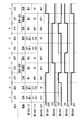
- ⁇ Power supply body Power supply parallel state-During regeneration> As shown in FIG. 2 (section B) and FIG. 4, when the ECU 90 determines that the power supply parallel state is selected and is in the regeneration mode, the AC from the second motor generator 120 that functions as a generator. The second inverter 20 is controlled so as to convert the power into DC power. Then, the converted DC power is charged in the first secondary battery 41 and the second secondary battery 42.
- the ECU 90 turns on the third switch 63 and operates the internal combustion engine to cause the first motor generator 110 to function as a generator, and to exchange AC power from the first motor generator 110. It is good also as a structure which is converted into direct-current power by the 1st inverter 10, and this direct-current power charges the 1st secondary battery 41 and the 2nd secondary battery 42 also.
- the ECU 90 controls the first inverter 10 to convert the DC power from the first secondary battery 41 and the second secondary battery 42 into AC power, and supplies the AC power to the first motor generator 110.
- the first motor The generator 110 is caused to function as a motor. As a result, the first rotor (not shown) of the first motor generator 110 rotates.
- a clutch mechanism is provided between the first rotor and the crankshaft, and when the first rotor is rotated, the clutch mechanism May be configured to be turned off (power is cut off). The same applies when switching from a power supply serial state to a power supply parallel state, which will be described later.
- the electromotive voltage generated by the first rotor that rotates inertially changes in accordance with the degree of rotation of the first rotor. That is, the electromotive voltage increases as the first rotor is rotated at a high speed. Therefore, for example, the first rotor rotates at high speed as the terminal voltage of the first secondary battery 41 increases so that the electromotive voltage generated thereafter becomes equal to or higher than the terminal voltage of the first secondary battery 41. It is preferable to increase the power supply amount to the first motor generator 110.
- the terminal voltage of the first secondary battery 41 is detected by a voltage sensor or the like.
- the ECU 90 turns on the fourth switch 64 and turns off the first switch 61, the second switch 62, the third switch 63, and the fifth switch 65.
- the power supply body 40 is in a single second power supply state in which only the second secondary battery 42 outputs (connects to the outside).
- the 1st inverter 10 will be in the 2nd connection state (series connection state) connected in series with the power supply main body 40 which is a single 2nd power supply state.
- the power supply from the power supply body 40 to the first inverter 10 is stopped by turning off the third switch 63, and the motor function of the first motor generator 110 is lost.
- the first rotor rotates by inertia (inertia) due to its own inertia, and the first motor generator 110 operates as a generator (provides a generator function), and AC power is generated in the first stator coils 111 to 113. Yes.
- the ECU 90 controls the first inverter 10 to convert AC power from the first motor generator 110 operating as a generator into DC power.
- the first inverter 10 temporarily becomes a DC power supply (booster), and the first inverter 10 is in a series connection state (second connection state) with the second secondary battery 42.
- the first inverter 10 is in parallel with the capacitor 51 and also in parallel with the first secondary battery 41 connected thereafter.
- the rotational speed of the first rotor is gradually reduced, the electromotive voltage of the first inverter 10 that is temporarily used as a power source is also gradually reduced.
- the electric charge is stored in the capacitor 51, the voltage of the capacitor 51 gradually increases.
- the power supply body 40 switches from the single second power supply state to the power supply serial state in which the first secondary battery 41 and the second secondary battery 42 are in series. Thereafter, the ECU 90 turns off the fourth switch 64.
- the first secondary battery 41 and the second second battery 42 are connected. Since the secondary battery 42 is switched to the power supply serial state in which the secondary battery 42 is in series, a sudden change in the applied voltage to the second inverter 20 is achieved with respect to the configuration in which the power supply parallel state is switched to the power supply serial state without going through the series connection state. Becomes smaller.
- the timing of switching from the single second power supply state to the power supply serial state is the timing at which the first power supply voltage (terminal voltage) of the first secondary battery 41, the electromotive voltage of the first inverter 10 and the voltage of the capacitor 51 are substantially equal. Is preferred. Therefore, it is good also as a structure provided with the voltage sensor which detects the 1st power supply voltage of the 1st secondary battery 41, the voltage sensor which detects the voltage of the capacitor
- ⁇ Power supply body Power supply in series-Powering>
- the ECU 90 turns on the second switch 62 when the power supply series state is selected, and the first switch 61, the third switch 63, the fourth switch 64, The fifth switch 65 is turned off. Then, the first secondary battery 41 and the second secondary battery 42 are in series.
- the ECU 90 determines that the power running is in progress, the ECU 90 controls the second inverter 20 so that the second motor generator 120 functions as a motor, and the first secondary battery 41 and the second secondary battery 42 The direct current power is converted into alternating current power and supplied to the second motor generator 120.
- the ECU 90 turns on the third switch 63 and operates the internal combustion engine.
- the first motor generator 110 may function as a generator, and AC power from the first motor generator 110 may be converted into DC power by the first inverter 10, and this DC power may be supplied to the second inverter 20.
- ⁇ Power supply body Power supply in series-during regeneration> As shown in FIG. 2 (section G) and FIG. 9, when the ECU 90 determines that the power supply series state is selected and is in the regeneration mode, the alternating current from the second motor generator 120 that functions as a generator. The second inverter 20 is controlled so as to convert the power into DC power. Then, the converted DC power is charged in the first secondary battery 41 and the second secondary battery 42.
- the ECU 90 turns on the third switch 63 and the like. Then, by operating the internal combustion engine, the first motor generator 110 functions as a generator, and AC power from the first motor generator 110 is converted into DC power by the first inverter 10, and this DC power is also converted into the first secondary battery. 41 and the second secondary battery 42 may be charged.
- first connection state As shown in FIG. 2 (section H) and FIG. 10, the ECU 90 turns on the third switch 63 while keeping the second switch 62 on. Note that the first switch 61, the fourth switch 64, and the fifth switch 65 remain OFF. Thereby, the power supply main body 40 and the 1st inverter 10 which are a power supply serial state will be in a 1st connection state.
- the ECU 90 controls the first inverter 10 to convert DC power from the first secondary battery 41 and the second secondary battery 42 into AC power and supply the AC power to the first motor generator 110.
- the first motor generator 110 is made to function as a motor. As a result, the first rotor (not shown) of the first motor generator 110 rotates.
- the ECU 90 turns on the fourth switch 64 and turns off the first switch 61, the second switch 62, the third switch 63, and the fifth switch 65.
- the power supply body 40 is in a single second power supply state in which only the second secondary battery 42 outputs (connects to the outside).
- the 1st inverter 10 will be in the 2nd connection state (series connection state) connected in series with the power supply main body 40 which is a single 2nd power supply state.
- the power supply from the power supply body 40 to the first inverter 10 is stopped by turning off the third switch 63, and the motor function of the first motor generator 110 is lost.
- the first rotor rotates by inertia (inertia) due to its own inertia, and the first motor generator 110 operates as a generator (provides a generator function), and AC power is generated in the first stator coils 111 to 113. Yes.
- the ECU 90 controls the first inverter 10 to convert AC power from the first motor generator 110 that operates as a generator into DC power. As a result, the first inverter 10 temporarily becomes a DC power supply, and the first inverter 10 is in series connection with the second secondary battery 42.
- the first inverter 10 is in parallel with the capacitor 51 and also in parallel with the first secondary battery 41 connected thereafter.
- the rotational speed of the first rotor is gradually reduced, the electromotive voltage of the first inverter 10 that is temporarily used as a power source is also gradually reduced.
- the electric charge is stored in the capacitor 51, the voltage of the capacitor 51 gradually increases.
- the power supply body 40 switches from the single second power supply state to the power supply parallel state in which the first secondary battery 41 and the second secondary battery 42 are in parallel. Thereafter, the ECU 90 turns off the fourth switch 64.
- the first secondary battery 41 and the second second battery 42 are connected. Since the secondary battery 42 is switched to the power supply parallel state in which the secondary battery 42 is in parallel, a sudden change in the applied voltage to the second inverter 20 with respect to the configuration in which the power supply serial state is switched to the power supply parallel state without going through the series connection state becomes smaller.
- timing of switching from the single second power supply state to the power supply parallel state is the timing at which the first power supply voltage (terminal voltage) of the first secondary battery 41, the electromotive voltage of the first inverter 10, and the voltage of the capacitor 51 are substantially equal. Is preferred.
- the configuration in which the external load to which the power supply device 1 is always connected is the second motor generator 120 that consumes AC power is exemplified.
- the external load consumes DC power.
- an electric heater may be used.
- the power supply device 1 becomes a structure which is not provided with the 2nd inverter 20.
- the third switch 63 when the rotor of the first motor generator 110 is rotated in the case of switching from the power supply parallel state to the power supply serial state, the third switch 63 is turned on to supply DC power from the power supply body 40 to the first inverter 10.
- the ECU 90 power source control means
- the internal combustion engine power source
- the third switch 63 it is good also as a structure which rotates the rotor of the 1st motor generator 110 with motive power. In this configuration, it is not necessary to turn on the third switch 63 for supplying power to the first inverter 10, and the third switch 63 remains off.
- ECU90 inverter connection means
- ECU90 turns ON the 4th switch 64, the 1st switch 61, the 2nd switch 62, the 3rd switch 63,
- the fifth switch 65 is turned off.
- the power supply body 40 is in a single second power supply state in which only the second secondary battery 42 outputs (connects to the outside).
- the 1st inverter 10 will be in the serial connection state in series with the power supply main body 40 which is a single 2nd power supply state.
- the third switch 63 when switching from the power supply series state to the power supply parallel state, when the rotor of the first motor generator 110 is rotated, the third switch 63 is turned on to supply DC power from the power supply body 40 to the first inverter 10.
- the ECU 90 power source control means
- the internal combustion engine power source
- the third switch 63 it is good also as a structure which rotates the rotor of the 1st motor generator 110 with motive power. In this configuration, it is not necessary to turn on the third switch 63 for supplying power to the first inverter 10, and the third switch 63 remains off.
- ECU90 inverter connection means
- ECU90 turns ON the 4th switch 64, the 1st switch 61, the 2nd switch 62, the 3rd switch 63,
- the fifth switch 65 is turned off.
- the power supply body 40 is in a single second power supply state in which only the second secondary battery 42 outputs (connects to the outside).
- the 1st inverter 10 will be in the serial connection state connected in series with the power supply main body 40 which is a single 2nd power supply state.
- the configuration in which the first power source is the first secondary battery 41 is exemplified.
- the first power source may be a primary battery.
- the second power source second secondary battery 42.
Landscapes
- Engineering & Computer Science (AREA)
- Power Engineering (AREA)
- Transportation (AREA)
- Mechanical Engineering (AREA)
- Life Sciences & Earth Sciences (AREA)
- Sustainable Development (AREA)
- Sustainable Energy (AREA)
- Electric Propulsion And Braking For Vehicles (AREA)
- Control Of Ac Motors In General (AREA)
Abstract
Description
このようにして、第2電源と一時的に電源となるインバータとの直列接続状態を経由するので、電源本体の電圧変動が小さくなる。
このようにして、第2電源と一時的に電源となるインバータとの直列接続状態を経由するので、電源本体の電圧変動が小さくなる。
第1モータジェネレータ110は、モータ(電動機)の機能と、ジェネレータ(発電機)の機能とを備えている。すなわち、第1モータジェネレータ110は、内燃機関側に配置されるので、主に内燃機関からの動力によってジェネレータとして機能するものの、電源本体40の電源並列状態及び電源直列状態の切替時、一時的にモータとして機能するように構成されている。
内燃機関は、例えばレシプロ型であり、燃料を燃焼させることでクランク軸を回転させて動力(回転力)を発生する動力発生装置である。内燃機関は、燃料及び空気の混合ガスを吸気する吸気弁と、燃焼後の排気ガスを排気する排気弁と、燃料を噴射するインジェクタと、吸気される空気の流量を制御するスロットル弁と、混合ガスに点火する点火プラグと、を備えている。そして、ECU90が、吸気弁、排気弁、インジェクタ、スロットル弁及び点火プラグを適宜に制御することで、内燃機関の出力(クランク軸の回転速度、トルク)が制御されるようになっている。
第2モータジェネレータ120は、モータ(電動機)の機能と、ジェネレータ(発電機)の機能とを備えている。すなわち、第2モータジェネレータ120は、(1)力行時、モータとして機能し、第2インバータ20からの交流電力(三相交流電力)を消費することで駆動力を発生し、(2)回生時、ジェネレータとして機能し、車輪の回転力によって交流電力を発生するようになっている。
電源装置1は、内燃機関側の第1インバータ10と、駆動輪側の第2インバータ20と、正極母線31及び負極母線32と、電源本体40と、コンデンサ51と、第1スイッチ61~第5スイッチ65と、補機71と、ECU90と、を備えている。
第1インバータ10は、内燃機関側の第1モータジェネレータ110との間で電力を授受する装置である。第1インバータ10は、具体的には、(1)発電時(第1ロータの慣性回転時を含む)、第1モータジェネレータ110からの交流電力を直流電力に変換し、電源本体40又は第2インバータ20に出力する機能を主に備えている。
この他、第1インバータ10は、第1二次電池41等からの直流電力を交流電力に変換して第1モータジェネレータ110に出力し、第1モータジェネレータ110を一時的にモータとする機能も備えている。
V相、W相は、U相と同様の接続状態であるので、説明を省略する。
第2インバータ20は、駆動輪側の第2モータジェネレータ120との間で電力を授受する装置である。第2インバータ20は、具体的には、(1)力行時、第1二次電池41、第2二次電池42、第1モータジェネレータ110からの直流電力を交流電力に変換し、第2モータジェネレータ120に出力する機能と、(2)回生時、第2モータジェネレータ120からの回生電力(交流電力)を直流電力に変換し、第1二次電池41等に出力する機能と、を備えている。
第2インバータ20におけるスイッチ21H等の接続状態は、第1インバータ10と同様であるので説明を省略する。
正極母線31は、電源装置1の正極側の母線であり、第2インバータ正極端子20Hと、第3スイッチ63のコレクタとに接続されている。なお、第3スイッチ63のエミッタは第1インバータ正極端子10Hに接続されている。負極母線32は、電源装置1の負極側の母線であり、第1インバータ負極端子10Lと、第2インバータ負極端子20Lとに接続されている。
電源本体40は、第1二次電池41(第1電源)と、第2二次電池42(第2電源)と、を備えている。第1二次電池41、第2二次電池42は、高圧電源であって、複数の単電池が直列接続されることで構成された組電池である。第1二次電池41、第2二次電池42は、直流電力を充放電(充電/放電)可能な二次電池であり、例えば、リチウムイオン型、リチウムイオンポリマー型、ニッケル水素型で構成されている。
コンデンサ51は、電荷を充放電するものである。コンデンサ51は、第5スイッチ65と並列に配置され、コンデンサ51の正極端子は第2電源負極端子42Lに接続されており、コンデンサ51の負極端子は負極母線32に電気的に接続されている。
第1スイッチ61~第5スイッチ65は、ECU90によってON(導通)/OFF(遮断)制御されるスイッチであり、例えばIGBTで構成される。
第2スイッチ62は、第1電源正極端子41Hと第2電源負極端子42Lとの接続状態をON/OFFするスイッチである。
第3スイッチ63は、正極母線31と第1インバータ正極端子10Hとの接続状態をON/OFFするスイッチである。
第5スイッチ65は、第2電源負極端子42Lと負極母線32との接続状態をON/OFFするスイッチである。
補機71は、第2モータジェネレータ120に対して低い動作電圧(例えば12V)で作動する機器であり、ヘッドライト、室内灯、ナビゲーション装置、等である。補機71は第1二次電池41に接続されており、補機71と第1二次電池41との間には電圧を降圧するDC/DCコンバータ(図示しない)が設けられている。
ECU90は、電源装置1を電子制御する制御装置であり、CPU、ROM、RAM、各種インタフェイス、電子回路などを含んで構成されている。そして、ECU90は、その内部に記憶されたプログラムに従って各種処理を実行するように構成されている。
ECU90は、車速やアクセル開度に基づいて力行時であるか否か判定する機能を備えている。アクセル開度はアクセル開度センサ(図示しない)を介して検出され、車速は車速センサ(図示しない)を介して検出される。そして、ECU90は、直前の所定単位時間において車速及び/又はアクセル開度が増加している場合、力行時であると判定するように構成されている。一方、ECU90は、車速又はアクセル開度が減少している場合、力行時でない、つまり回生時であると判定するように構成されている。
ここで、第1二次電池41、第2二次電池42、内燃機関側の第1インバータ10の接続状態を説明する。なお、ECU90が、第1スイッチ61等を適宜にON/OFFすることで、後記する接続状態が適宜に切り替えられるように構成されている。
第1スイッチ61及び第5スイッチ65がON状態、第2スイッチ62がOFF状態であると、負荷(第2インバータ20)に対して、第1二次電池41及び第2二次電池42が並列となる電源並列状態となる。
第2スイッチ62がON状態、第1スイッチ61及び第5スイッチ65がOFF状態であると、負荷(第2インバータ20)に対して、第1二次電池41及び第2二次電池42が直列となる電源直列状態となる。
ECU90は、動力源である第2モータジェネレータ120に要求される要求トルクと、車速と、接続状態マップとに基づいて、電源並列状態又は電源直列状態を選択し、選択した接続状態となるように第1スイッチ61等をON/OFF制御する機能を備えている。
第1スイッチ61及び第2スイッチ62がOFF状態であると、第2二次電池42のみが単独で出力する単独第2電源状態となる。なお、本実施形態では、単独第2電源状態において、第5スイッチ65もOFF状態となる。
したがって、本実施形態において、電源並列状態、電源直列状態、単独第2電源状態を切り替える電源状態切替手段は、第1スイッチ61、第2スイッチ62、第4スイッチ64、第5スイッチ65と、これらを制御するECU90とを備えて構成されている。
電源本体40が電源並列状態又は電源直列状態である場合において、第3スイッチ63がON状態、第4スイッチ64がOFF状態であると、第1インバータ10は第1接続状態となる。第1接続状態では、(1)電源本体40の電力を第1インバータ10に供給し第1モータジェネレータ110をモータとして機能させることや、(2)ジェネレータとして機能する第1モータジェネレータ110の電力を電源本体40及び/又は第2インバータ20に供給することが可能となる。
電源本体40が単独第2電源状態である場合において、第3スイッチ63がOFF状態、第4スイッチ64がON状態であると、第1インバータ10は第2接続状態となる。
したがって、本実施形態において、第1接続状態と第2接続状態とに切り替えるインバータ接続状態切替手段は、第3スイッチ63、第4スイッチ64と、これらを制御するECU90とを備えて構成されている。
電源装置1の作用効果を説明する。
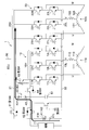
図2(区間A)、図3に示すように、ECU90は、電源並列状態を選択している場合、第1スイッチ61、第5スイッチ65をONし、第2スイッチ62、第3スイッチ63、第4スイッチ64をOFFする。そうすると、第1二次電池41及び第2二次電池42は電源並列状態となる。
図2(区間B)、図4に示すように、ECU90は、電源並列状態を選択している場合であって回生時であると判定した場合、ジェネレータとして機能する第2モータジェネレータ120からの交流電力を直流電力に変換するように第2インバータ20を制御する。そうすると、変換後の直流電力が第1二次電池41及び第2二次電池42に充電される。
次に、図2(区間C~E)、図5~図7を参照して、電源並列状態から電源直列状態に切り替える場合を説明する。
図2(区間C)、図5に示すように、ECU90は、第1スイッチ61、第5スイッチ65をONしたまま、第3スイッチ63もONする。なお、第2スイッチ62、第4スイッチ64はOFFのままである。これにより、電源並列状態である電源本体40と第1インバータ10とは第1接続状態となる。
次いで、ECU90は、第1インバータ10を制御して、第1二次電池41及び第2二次電池42からの直流電力を交流電力に変換して第1モータジェネレータ110に供給し、第1モータジェネレータ110をモータとして機能させる。これにより、第1モータジェネレータ110の第1ロータ(図示しない)は回転する。
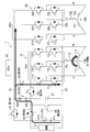
次いで、図2(区間D)、図6に示すように、ECU90は、第4スイッチ64をONし、第1スイッチ61、第2スイッチ62、第3スイッチ63、第5スイッチ65をOFFする。これにより、電源本体40は、第2二次電池42のみが出力(外部と接続)する単独第2電源状態となる。第1インバータ10は、単独第2電源状態である電源本体40と直列接続した第2接続状態(直列接続状態)となる。
この状態において、第1ロータの回転速度は徐々に小さくなるので、一時的に電源となる第1インバータ10の起電圧も徐々に小さくなる。一方、コンデンサ51には電荷が蓄えられるので、コンデンサ51の電圧は徐々に大きくなる。
次いで、図2(区間E)、図7に示すように、ECU90は、第4スイッチ64をONしたまま、第2スイッチ62をONする。なお、第1スイッチ61、第3スイッチ63、第5スイッチ65はOFFのままである。
図2(区間F)、図8に示すように、ECU90は、電源直列状態を選択している場合、第2スイッチ62をONし、第1スイッチ61、第3スイッチ63、第4スイッチ64、第5スイッチ65をOFFする。そうすると、第1二次電池41及び第2二次電池42は直列状態となる。
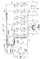
図2(区間G)、図9に示すように、ECU90は、電源直列状態を選択している場合であって回生時であると判定した場合、ジェネレータとして機能する第2モータジェネレータ120からの交流電力を直流電力に変換するように第2インバータ20を制御する。そうすると、変換後の直流電力が第1二次電池41及び第2二次電池42に充電される。
次に、図2(区間H~J)、図10~図11を参照して、電源直列状態から電源並列状態に切り替える場合を説明する。
図2(区間H)、図10に示すように、ECU90は、第2スイッチ62をONしたまま、第3スイッチ63もONする。なお、第1スイッチ61、第4スイッチ64、第5スイッチ65はOFFのままである。これにより、電源直列状態である電源本体40と第1インバータ10とは第1接続状態となる。
次いで、ECU90は、第1インバータ10を制御して、第1二次電池41及び第2二次電池42から直流電力を交流電力に変換して第1モータジェネレータ110に供給し、第1モータジェネレータ110をモータとして機能させる。これにより、第1モータジェネレータ110の第1ロータ(図示しない)は回転する。
次いで、図2(区間I)、図11に示すように、ECU90は、第4スイッチ64をONし、第1スイッチ61、第2スイッチ62、第3スイッチ63、第5スイッチ65をOFFする。これにより、電源本体40は、第2二次電池42のみが出力(外部と接続)する単独第2電源状態となる。第1インバータ10は、単独第2電源状態である電源本体40と直列接続した第2接続状態(直列接続状態)となる。
次いで、ECU90は、第1インバータ10を制御して、ジェネレータとして作動する第1モータジェネレータ110からの交流電力を直流電力に変換する。これにより、第1インバータ10は一時的に直流電源となると共に、第1インバータ10は第2二次電池42と直列接続状態となる。
この状態において、第1ロータの回転速度は徐々に小さくなるので、一時的に電源となる第1インバータ10の起電圧も徐々に小さくなる。一方、コンデンサ51には電荷が蓄えられるので、コンデンサ51の電圧は徐々に大きくなる。
次いで、図2(区間J)、図12に示すように、ECU90は、第4スイッチ64をONしたまま、第1スイッチ61、第5スイッチ65をONする。なお、第2スイッチ62、第3スイッチ63はOFFのままである。
以上、本発明の一実施形態について説明したが、本発明はこれに限定されず、例えば、次のように変更してもよい。
この構成の場合、第1インバータ10に電力供給するための第3スイッチ63のONは不要となり、第3スイッチ63はOFFのままとなる。
この構成の場合、第1インバータ10に電力供給するための第3スイッチ63のONは不要となり、第3スイッチ63はOFFのままとなる。
10 第1インバータ
20 第2インバータ
10H 第1インバータ正極端子
10L 第1インバータ負極端子
20 第2インバータ
31 正極母線
32 負極母線
40 電源本体
41 第1二次電池(第1電源)
41H 第1電源正極端子
41L 第1電源負極端子
42 第2二次電池(第2電源)
42H 第2電源正極端子
42L 第2電源負極端子
61 第1スイッチ
62 第2スイッチ
63 第3スイッチ
64 第4スイッチ
65 第5スイッチ
90 ECU
110 第1モータジェネレータ
120 第2モータジェネレータ
Claims (5)
- 第1電源及び第2電源を有する電源本体と、
前記第1電源及び前記第2電源の電源並列状態と、電源直列状態と、前記第2電源のみが出力する単独第2電源状態と、に切り替える電源状態切替手段と、
モータジェネレータに接続するインバータと、
電源並列状態又は電源直列状態の前記電源本体と前記インバータとが接続した第1接続状態と、単独第2電源状態の前記電源本体と前記インバータとが直列接続した第2接続状態と、に切り替えるインバータ接続状態切替手段と、
を備え、
前記電源状態切替手段が電源並列状態から電源直列状態に切り替える場合、
前記インバータ接続状態切替手段が第1接続状態に切り替え、
前記インバータが前記モータジェネレータをモータとして作動させた後、
前記電源状態切替手段が単独第2電源状態に切り替え、前記インバータ接続状態切替手段が第2接続状態に切り替え、前記第2電源とジェネレータとして作動する前記モータジェネレータによって電源となる前記インバータとの直列接続状態を経由した後、
前記電源状態切替手段が電源直列状態に切り替える
ことを特徴とする電源装置。 - 第1電源及び第2電源を有する電源本体と、
前記第1電源及び前記第2電源の電源並列状態と、電源直列状態と、前記第2電源のみが出力する単独第2電源状態と、に切り替える電源状態切替手段と、
モータジェネレータに接続するインバータと、
電源並列状態又は電源直列状態の前記電源本体と前記インバータとが接続した第1接続状態と、単独第2電源状態の前記電源本体と前記インバータとが直列接続した第2接続状態と、に切り替えるインバータ接続状態切替手段と、
を備え、
前記電源状態切替手段が電源直列状態から電源並列状態に切り替える場合、
前記インバータ接続状態切替手段が第1接続状態に切り替え、
前記インバータが前記モータジェネレータをモータとして作動させた後、
前記電源状態切替手段が単独第2電源状態に切り替え、前記インバータ接続状態切替手段が第2接続状態に切り替え、前記第2電源とジェネレータとして作動する前記モータジェネレータによって電源となる前記インバータとの直列接続状態を経由した後、
前記電源状態切替手段が電源並列状態に切り替える
ことを特徴とする電源装置。 - 前記第1電源は、第1電源正極端子と、第1電源負極端子と、を備え、
前記第2電源は、第2電源正極端子と、第2電源負極端子と、を備え、
前記インバータは、インバータ正極端子と、インバータ負極端子と、を備え、
前記第2電源正極端子に接続した正極母線と、
前記第1電源負極端子及び前記インバータ負極端子に接続した負極母線と、
前記第1電源正極端子と前記正極母線との接続をON/OFFする第1スイッチと、
前記第1電源正極端子と前記第2電源負極端子との接続をON/OFFする第2スイッチと、
前記正極母線と前記インバータ正極端子との接続をON/OFFする第3スイッチと、
前記第2電源負極端子と前記インバータ正極端子との接続をON/OFFする第4スイッチと、
前記第2電源負極端子と前記負極母線との接続をON/OFFする第5スイッチと、
を備える
ことを特徴とする請求項1又は請求項2に記載の電源装置。 - 第1電源及び第2電源を有する電源本体と、
前記第1電源及び前記第2電源の電源並列状態と、電源直列状態と、前記第2電源のみが出力する単独第2電源状態と、に切り替える電源状態切替手段と、
ジェネレータに接続するインバータと、
単独第2電源状態の前記電源本体と前記インバータとが直列接続した直列接続状態で接続するインバータ接続手段と、
前記ジェネレータのロータを回転させる動力源を制御する動力源制御手段と、
を備え、
前記電源状態切替手段が電源並列状態から電源直列状態に切り替える場合、
前記動力源制御手段が前記ロータを回転させた後、
前記電源状態切替手段が単独第2電源状態に切り替え、前記インバータ接続手段が直列接続状態に切り替え、前記第2電源と作動する前記ジェネレータによって電源となる前記インバータとの直列接続状態を経由した後、
前記電源状態切替手段が電源直列状態に切り替える
ことを特徴とする電源装置。 - 第1電源及び第2電源を有する電源本体と、
前記第1電源及び前記第2電源の電源並列状態と、電源直列状態と、前記第2電源のみが出力する単独第2電源状態と、に切り替える電源状態切替手段と、
ジェネレータに接続するインバータと、
単独第2電源状態の前記電源本体と前記インバータとが直列接続した直列接続状態で接続するインバータ接続手段と、
前記ジェネレータのロータを回転させる動力源を制御する動力源制御手段と、
を備え、
前記電源状態切替手段が電源直列状態から電源並列状態に切り替える場合、
前記動力源制御手段が前記ロータを回転させた後、
前記電源状態切替手段が単独第2電源状態に切り替え、前記インバータ接続手段が直列接続状態に切り替え、前記第2電源と作動する前記ジェネレータによって電源となる前記インバータとの直列接続状態を経由した後、
前記電源状態切替手段が電源並列状態に切り替える
ことを特徴とする電源装置。
Priority Applications (5)
| Application Number | Priority Date | Filing Date | Title |
|---|---|---|---|
| US14/441,132 US9564840B2 (en) | 2012-11-09 | 2013-11-08 | Power source device |
| CA2890391A CA2890391A1 (en) | 2012-11-09 | 2013-11-08 | Power source device |
| JP2014545763A JP5852748B2 (ja) | 2012-11-09 | 2013-11-08 | 電源装置 |
| CN201380056470.3A CN104756397B (zh) | 2012-11-09 | 2013-11-08 | 电源装置 |
| EP13854115.6A EP2919382A4 (en) | 2012-11-09 | 2013-11-08 | POWER SOURCE DEVICE |
Applications Claiming Priority (2)
| Application Number | Priority Date | Filing Date | Title |
|---|---|---|---|
| JP2012247883 | 2012-11-09 | ||
| JP2012-247883 | 2012-11-09 |
Publications (1)
| Publication Number | Publication Date |
|---|---|
| WO2014073632A1 true WO2014073632A1 (ja) | 2014-05-15 |
Family
ID=50684729
Family Applications (1)
| Application Number | Title | Priority Date | Filing Date |
|---|---|---|---|
| PCT/JP2013/080191 WO2014073632A1 (ja) | 2012-11-09 | 2013-11-08 | 電源装置 |
Country Status (7)
| Country | Link |
|---|---|
| US (1) | US9564840B2 (ja) |
| EP (1) | EP2919382A4 (ja) |
| JP (1) | JP5852748B2 (ja) |
| KR (1) | KR20150083911A (ja) |
| CN (1) | CN104756397B (ja) |
| CA (1) | CA2890391A1 (ja) |
| WO (1) | WO2014073632A1 (ja) |
Cited By (2)
| Publication number | Priority date | Publication date | Assignee | Title |
|---|---|---|---|---|
| JP2016021849A (ja) * | 2014-06-20 | 2016-02-04 | トヨタ自動車株式会社 | 車両の制御装置 |
| CN110949157A (zh) * | 2019-12-27 | 2020-04-03 | 成都图翎数控科技有限公司 | 一种牵引机车的充电装置、系统及方法 |
Families Citing this family (11)
| Publication number | Priority date | Publication date | Assignee | Title |
|---|---|---|---|---|
| CN104242784A (zh) * | 2014-09-22 | 2014-12-24 | 中国北方车辆研究所 | 一种伺服电机的驱动与控制电路 |
| EP3113315A1 (en) * | 2015-07-02 | 2017-01-04 | Hella KGaA Hueck & Co | Automotive dual voltage battery charging system |
| JP2017158318A (ja) * | 2016-03-02 | 2017-09-07 | 日立オートモティブシステムズ株式会社 | モータ駆動装置 |
| DE102016211164A1 (de) * | 2016-06-22 | 2017-12-28 | Robert Bosch Gmbh | Kraftfahrzeugbordnetz mit wenigstens zwei Energiespeichern, Verfahren zum Betreiben eines Kraftfahrzeugbordnetzes und Mittel zu dessen Implementierung |
| CN114430088A (zh) * | 2016-10-31 | 2022-05-03 | 工机控股株式会社 | 电池组以及使用电池组的电动机器、电动机器系统 |
| CN107196576B (zh) * | 2017-07-06 | 2019-09-10 | 中国计量大学 | 一种开关磁阻电机功率变换器及其控制方法 |
| JP6972140B2 (ja) * | 2017-09-08 | 2021-11-24 | 新電元工業株式会社 | 電力制御装置、および、電力制御装置の制御方法 |
| WO2019049340A1 (ja) * | 2017-09-08 | 2019-03-14 | 新電元工業株式会社 | 電力制御装置、および、電力制御装置の制御方法 |
| KR102614137B1 (ko) * | 2018-04-13 | 2023-12-14 | 현대자동차주식회사 | 차량용 인버터 시스템 및 그 제어방법 |
| CN112106269B (zh) * | 2018-05-16 | 2023-08-25 | 本田技研工业株式会社 | 电力消耗控制装置 |
| RU2735322C1 (ru) * | 2019-12-23 | 2020-10-30 | Федеральное государственное бюджетное образовательное учреждение высшего образования "Московский автомобильно-дорожный государственный технический университет (МАДИ)" | Способ стабилизации частоты выходного напряжения автономного источника электропитания с силовой установкой внутреннего сгорания |
Citations (3)
| Publication number | Priority date | Publication date | Assignee | Title |
|---|---|---|---|---|
| JP2012060838A (ja) | 2010-09-10 | 2012-03-22 | Toyota Motor Corp | 電源装置および車両 |
| JP2012070514A (ja) | 2010-09-22 | 2012-04-05 | Toyota Central R&D Labs Inc | 電源システム |
| JP2012152079A (ja) * | 2011-01-21 | 2012-08-09 | Honda Motor Co Ltd | 電動車両用電源装置 |
Family Cites Families (15)
| Publication number | Priority date | Publication date | Assignee | Title |
|---|---|---|---|---|
| US5349517A (en) * | 1993-08-19 | 1994-09-20 | Westinghouse Electric Corporation | Active power line conditioner utilizing harmonic frequency injection for improved peak voltage regulation |
| US5771161A (en) * | 1997-01-10 | 1998-06-23 | Northrop Grumman Corporation | Uninterruptable capability for an active power line conditioner |
| US6281664B1 (en) * | 1999-01-13 | 2001-08-28 | Honda Giken Kogyo Kabushiki Kaisha | Generator and generator apparatus |
| JP3794224B2 (ja) * | 1999-11-04 | 2006-07-05 | マツダ株式会社 | 車両用電源装置 |
| JP4641124B2 (ja) * | 2001-08-02 | 2011-03-02 | 本田技研工業株式会社 | 多重結合インバータ装置 |
| JP2004080931A (ja) * | 2002-08-20 | 2004-03-11 | Kokusan Denki Co Ltd | 内燃機関用スタータジェネレータ |
| JP4779947B2 (ja) | 2006-11-24 | 2011-09-28 | 日産自動車株式会社 | 車両の電力供給装置 |
| JP5182504B2 (ja) * | 2008-08-28 | 2013-04-17 | 日産自動車株式会社 | 電力供給装置およびその制御方法 |
| JP2010183768A (ja) | 2009-02-06 | 2010-08-19 | Nissan Motor Co Ltd | 電源装置および電源装置の制御方法 |
| JP4444365B1 (ja) * | 2009-07-01 | 2010-03-31 | 英生 住野 | 犬用のダイエット食品の製造方法 |
| US20120206076A1 (en) * | 2009-10-28 | 2012-08-16 | Shouichi Tanaka | Motor-driving apparatus for variable-speed motor |
| JP2011109789A (ja) * | 2009-11-17 | 2011-06-02 | Fuji Electric Holdings Co Ltd | 電力変換装置 |
| CN102958745B (zh) * | 2010-06-29 | 2015-07-08 | 本田技研工业株式会社 | 电动汽车 |
| JP5264941B2 (ja) * | 2011-01-21 | 2013-08-14 | 本田技研工業株式会社 | 電動車両用電源装置 |
| JP5255086B2 (ja) * | 2011-04-08 | 2013-08-07 | 本田技研工業株式会社 | 電源装置及びその制御方法 |
-
2013
- 2013-11-08 KR KR1020157015318A patent/KR20150083911A/ko not_active Application Discontinuation
- 2013-11-08 CA CA2890391A patent/CA2890391A1/en not_active Abandoned
- 2013-11-08 JP JP2014545763A patent/JP5852748B2/ja not_active Expired - Fee Related
- 2013-11-08 EP EP13854115.6A patent/EP2919382A4/en not_active Withdrawn
- 2013-11-08 CN CN201380056470.3A patent/CN104756397B/zh active Active
- 2013-11-08 WO PCT/JP2013/080191 patent/WO2014073632A1/ja active Application Filing
- 2013-11-08 US US14/441,132 patent/US9564840B2/en active Active
Patent Citations (3)
| Publication number | Priority date | Publication date | Assignee | Title |
|---|---|---|---|---|
| JP2012060838A (ja) | 2010-09-10 | 2012-03-22 | Toyota Motor Corp | 電源装置および車両 |
| JP2012070514A (ja) | 2010-09-22 | 2012-04-05 | Toyota Central R&D Labs Inc | 電源システム |
| JP2012152079A (ja) * | 2011-01-21 | 2012-08-09 | Honda Motor Co Ltd | 電動車両用電源装置 |
Non-Patent Citations (1)
| Title |
|---|
| See also references of EP2919382A4 |
Cited By (4)
| Publication number | Priority date | Publication date | Assignee | Title |
|---|---|---|---|---|
| JP2016021849A (ja) * | 2014-06-20 | 2016-02-04 | トヨタ自動車株式会社 | 車両の制御装置 |
| US10059209B2 (en) | 2014-06-20 | 2018-08-28 | Toyota Jidosha Kabushiki Kaisha | Vehicle control device |
| CN110949157A (zh) * | 2019-12-27 | 2020-04-03 | 成都图翎数控科技有限公司 | 一种牵引机车的充电装置、系统及方法 |
| CN110949157B (zh) * | 2019-12-27 | 2021-06-29 | 成都图翎数控科技有限公司 | 一种牵引机车的充电装置、系统及方法 |
Also Published As
| Publication number | Publication date |
|---|---|
| JP5852748B2 (ja) | 2016-02-03 |
| KR20150083911A (ko) | 2015-07-20 |
| CN104756397A (zh) | 2015-07-01 |
| EP2919382A4 (en) | 2016-09-14 |
| CN104756397B (zh) | 2017-08-25 |
| CA2890391A1 (en) | 2014-05-15 |
| US20150303838A1 (en) | 2015-10-22 |
| EP2919382A1 (en) | 2015-09-16 |
| JPWO2014073632A1 (ja) | 2016-09-08 |
| US9564840B2 (en) | 2017-02-07 |
Similar Documents
| Publication | Publication Date | Title |
|---|---|---|
| JP5852748B2 (ja) | 電源装置 | |
| JP5321660B2 (ja) | 車両の制御装置及び制御方法 | |
| US6476571B1 (en) | Multiple power source system and apparatus, motor driving apparatus, and hybrid vehicle with multiple power source system mounted thereon | |
| KR101766094B1 (ko) | 하이브리드 차량의 출력 제어 시스템 | |
| CN1986308B (zh) | 一种弱混合轿车用电机控制系统 | |
| US9718372B2 (en) | Control apparatus for vehicle and vehicle | |
| US9649945B2 (en) | Vehicle and method of controlling the vehicle | |
| US8091666B2 (en) | Electrically powered vehicle, control device for electrically powered vehicle, and computer readable medium | |
| WO2012086021A1 (ja) | 車両、車両の制御方法および車両の制御装置 | |
| US10483841B2 (en) | Motor vehicle | |
| US8912764B2 (en) | Power control unit and control method for power control unit | |
| JP5747988B2 (ja) | 車両、および、車両の制御方法ならびに制御装置 | |
| JP2005318753A (ja) | 交流回転電機の制御方法及び車載電機システム並びに移動体 | |
| US10259446B1 (en) | Hybrid vehicle | |
| JP2012249455A (ja) | 車両の電気システム | |
| CN101335462A (zh) | 车辆电池充电器及其操作方法 | |
| KR20140071593A (ko) | 하이브리드 차량의 충전 제어 방법 | |
| JP5803462B2 (ja) | ハイブリッド車両およびその制御方法 | |
| JP5621264B2 (ja) | 車両の電気システム | |
| US10427528B2 (en) | Vehicle | |
| WO2021255939A1 (ja) | エンジン発電機 | |
| JPH06317169A (ja) | 回転電機付ターボチャージャ制御装置 | |
| JP2010179806A (ja) | ハイブリッド自動車 | |
| JP2022169023A (ja) | 制御装置 | |
| KR19990017612A (ko) | 하이브리드 자동차용 보조전력장치의 제어시스템 |
Legal Events
| Date | Code | Title | Description |
|---|---|---|---|
| 121 | Ep: the epo has been informed by wipo that ep was designated in this application |
Ref document number: 13854115 Country of ref document: EP Kind code of ref document: A1 |
|
| ENP | Entry into the national phase |
Ref document number: 2014545763 Country of ref document: JP Kind code of ref document: A |
|
| ENP | Entry into the national phase |
Ref document number: 2890391 Country of ref document: CA |
|
| WWE | Wipo information: entry into national phase |
Ref document number: 14441132 Country of ref document: US |
|
| NENP | Non-entry into the national phase |
Ref country code: DE |
|
| REEP | Request for entry into the european phase |
Ref document number: 2013854115 Country of ref document: EP |
|
| WWE | Wipo information: entry into national phase |
Ref document number: 2013854115 Country of ref document: EP |
|
| ENP | Entry into the national phase |
Ref document number: 20157015318 Country of ref document: KR Kind code of ref document: A |