WO2014073322A1 - Dispositif de détection d'objet et procédé de détection d'objet - Google Patents
Dispositif de détection d'objet et procédé de détection d'objet Download PDFInfo
- Publication number
- WO2014073322A1 WO2014073322A1 PCT/JP2013/077694 JP2013077694W WO2014073322A1 WO 2014073322 A1 WO2014073322 A1 WO 2014073322A1 JP 2013077694 W JP2013077694 W JP 2013077694W WO 2014073322 A1 WO2014073322 A1 WO 2014073322A1
- Authority
- WO
- WIPO (PCT)
- Prior art keywords
- image
- object detection
- gray
- distance
- vehicle
- Prior art date
Links
Images


Classifications
-
- G—PHYSICS
- G08—SIGNALLING
- G08G—TRAFFIC CONTROL SYSTEMS
- G08G1/00—Traffic control systems for road vehicles
- G08G1/16—Anti-collision systems
- G08G1/166—Anti-collision systems for active traffic, e.g. moving vehicles, pedestrians, bikes
-
- G—PHYSICS
- G06—COMPUTING; CALCULATING OR COUNTING
- G06V—IMAGE OR VIDEO RECOGNITION OR UNDERSTANDING
- G06V20/00—Scenes; Scene-specific elements
- G06V20/60—Type of objects
- G06V20/64—Three-dimensional objects
-
- G—PHYSICS
- G06—COMPUTING; CALCULATING OR COUNTING
- G06T—IMAGE DATA PROCESSING OR GENERATION, IN GENERAL
- G06T7/00—Image analysis
- G06T7/10—Segmentation; Edge detection
- G06T7/11—Region-based segmentation
-
- G—PHYSICS
- G06—COMPUTING; CALCULATING OR COUNTING
- G06T—IMAGE DATA PROCESSING OR GENERATION, IN GENERAL
- G06T7/00—Image analysis
- G06T7/10—Segmentation; Edge detection
- G06T7/187—Segmentation; Edge detection involving region growing; involving region merging; involving connected component labelling
-
- G—PHYSICS
- G06—COMPUTING; CALCULATING OR COUNTING
- G06V—IMAGE OR VIDEO RECOGNITION OR UNDERSTANDING
- G06V20/00—Scenes; Scene-specific elements
- G06V20/50—Context or environment of the image
- G06V20/56—Context or environment of the image exterior to a vehicle by using sensors mounted on the vehicle
- G06V20/58—Recognition of moving objects or obstacles, e.g. vehicles or pedestrians; Recognition of traffic objects, e.g. traffic signs, traffic lights or roads
-
- G—PHYSICS
- G06—COMPUTING; CALCULATING OR COUNTING
- G06V—IMAGE OR VIDEO RECOGNITION OR UNDERSTANDING
- G06V40/00—Recognition of biometric, human-related or animal-related patterns in image or video data
- G06V40/10—Human or animal bodies, e.g. vehicle occupants or pedestrians; Body parts, e.g. hands
- G06V40/103—Static body considered as a whole, e.g. static pedestrian or occupant recognition
-
- G—PHYSICS
- G06—COMPUTING; CALCULATING OR COUNTING
- G06T—IMAGE DATA PROCESSING OR GENERATION, IN GENERAL
- G06T2207/00—Indexing scheme for image analysis or image enhancement
- G06T2207/10—Image acquisition modality
- G06T2207/10016—Video; Image sequence
- G06T2207/10021—Stereoscopic video; Stereoscopic image sequence
-
- G—PHYSICS
- G06—COMPUTING; CALCULATING OR COUNTING
- G06T—IMAGE DATA PROCESSING OR GENERATION, IN GENERAL
- G06T2207/00—Indexing scheme for image analysis or image enhancement
- G06T2207/10—Image acquisition modality
- G06T2207/10028—Range image; Depth image; 3D point clouds
-
- G—PHYSICS
- G06—COMPUTING; CALCULATING OR COUNTING
- G06T—IMAGE DATA PROCESSING OR GENERATION, IN GENERAL
- G06T2207/00—Indexing scheme for image analysis or image enhancement
- G06T2207/30—Subject of image; Context of image processing
- G06T2207/30248—Vehicle exterior or interior
- G06T2207/30252—Vehicle exterior; Vicinity of vehicle
- G06T2207/30261—Obstacle
Definitions
- the present invention relates to an object detection apparatus and an object detection method for detecting an object based on a distance image generated based on a pair of gray-scale images.
- Patent Document 1 in an object detection apparatus that detects an object based on a distance image generated by stereo image processing, the reliability of distance data of the distance image is evaluated to extract effective distance data and invalid distance data. It is disclosed to perform grouping that is regarded as the same object based on the effective distance data and the invalid distance data.
- an object of this invention is to provide the object detection apparatus and object detection method which can suppress the error of grouping based on a distance image.
- an object detection apparatus includes a distance image generation unit that generates a distance image based on a pair of gray-scale images, a grouping unit that groups adjacent regions having similar distance data in the distance image, and the grouping And a division unit configured to divide the selected area based on the grayscale image.
- a step of generating a distance image based on a pair of gray-scale images, a step of grouping adjacent regions having similar distance data in the distance image, and the grouped regions are described above. And D. dividing based on a gray-scale image.
- FIG. 1 It is a block diagram which shows the structure of the vehicle driving assistance system in embodiment of this invention. It is a block diagram of the camera unit in embodiment of this invention, and an image signal processing unit. It is a figure which shows the example of arrangement
- FIG. 1 shows a configuration of a vehicle driving support system that implements forward collision warning (FCW) and inter-vehicle distance control (ACC: adaptive cruise control) as an example of an object detection apparatus and method according to the present invention. It is a block diagram.
- FCW forward collision warning
- ACC inter-vehicle distance control
- a camera unit (stereo camera) 101 is installed on the vehicle so as to capture the view in front of the vehicle 107.
- the vehicle forward image captured by the camera unit 101 is input to the image signal processing unit 102, and the image signal processing unit 102 calculates the distance to the preceding vehicle and the relative speed based on the vehicle forward image, and the distance to the preceding vehicle
- the information such as the relative velocity and the like is transmitted to the control unit 103.
- the control unit 103 determines the degree of risk of collision based on the distance to the preceding vehicle and the relative speed, and issues a warning sound (forward collision warning) with the speaker 104 or decelerates with the brake 106 according to the degree of danger, etc. Output the command of Further, when the driver of the vehicle 107 enables the ACC function, the control unit 103 controls the accelerator 105 and the brake 106 to cause the own vehicle to follow the preceding vehicle while maintaining a constant inter-vehicle distance, or the preceding vehicle If not, control (inter-vehicle distance control) to accelerate to a set vehicle speed is performed.
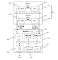
- FIG. 2 is a block diagram showing an internal configuration of the camera unit 101 and the image signal processing unit 102. As shown in FIG.
- the camera unit 101 includes a pair of left and right cameras 101a and 101b, and the cameras 101a and 101b include complementary metal oxide semiconductors (CMOSs) 201a and 201b and digital signal processors (DSPs) 202a and 202b, respectively.
- CMOSs complementary metal oxide semiconductors
- DSPs digital signal processors
- the photodiode is an imaging device in which photodiodes that convert light into charge are arranged in a grid.
- the CMOS 201 is a color element
- the RAW image (color image) of the CMOS 201 is transferred to the DSP 202 and converted to a gray-scale image in the DSP 202.
- the CMOS 201 is a monochrome element
- the gray image is transmitted to the image input I / F 205 of the image signal processing unit 102 as it is.
- the image signal is continuously transmitted from the camera unit 101 to the image input I / F 205, the synchronization signal is included at the beginning of the image signal, and the image input I / F 205 takes in only the image of the necessary timing. It is possible to A pair of left and right gray-scale images captured in the image signal processing unit 102 via the image input I / F 205 is written to the memory 206, and the image processing unit 204 performs parallax calculation processing based on the image stored in the memory 206. Perform analysis processing etc.
- a series of processing in the image processing unit 204 is performed according to a program 207 written in advance in the flash ROM.
- the CPU 203 performs control for capturing an image by the image input I / F 205, image processing by the image processing unit 204, and necessary calculations.
- the CMOSs 201a and 201b incorporate an exposure control unit for performing exposure control and a register for setting an exposure time, and the CMOS 201a and 201b capture an image with the exposure time set in the register.
- the exposure time set in the register can be rewritten by the CPU 203, and the exposure time rewritten by the CPU 203 is reflected at the time of imaging of the next frame or the subsequent field.
- the exposure time can be electronically controlled, and the exposure time limits the amount of light impinging on the CMOS 201a, 201b.
- the exposure time control can be realized by the electronic shutter method as described above, but can also be realized similarly by using a method of opening and closing the mechanical shutter. Further, the exposure amount can be changed by adjusting the aperture. Further, when scanning every other line as in the interlace, the exposure amount can be changed between the odd lines and the even lines.
- the image signal processing unit 102 transmits information such as the distance to the preceding vehicle and the relative speed to the control unit 103 via the CANI / F 208, and the control unit 103 generates a forward collision warning and an inter-vehicle distance based on the transmitted information. Implement control etc.
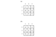
- each pixel measures the intensity of one of red (R), green (G), and blue (B), and the other colors refer to surrounding colors.
- R red
- G green
- B blue
- the RGB of the G22 pixel at the center of FIG. 3A can be calculated as shown in Equation 1.
- the RGB of the R22 pixel at the center of FIG. 3B can be calculated as Equation 2.
- RGB can be similarly determined for pixels other than G22 and R22, and the intensities of the three primary colors of RGB are calculated for all pixels to obtain a color image. Then, the lightness Y at all the pixels is calculated according to Equation 3 to create a Y image, and the Y image is used as a gray-scale image.
- the distance data from the left and right images taken by the left and right cameras 101a and 101b to the surface of the camera and the object (obstacle) can be output in the form of an image as distance data for each pixel.
- the format distance data is called a distance image.
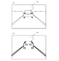
- FIG. 4 is a diagram for explaining the distance measurement principle (triangulation) using the pair of left and right cameras 101a and 101b.
- FIG. 4 a certain point P on the back of a vehicle 402 (preceding vehicle) which is a subject is shown at point Pr on the right camera image (reference image) and at point P1 on the left camera image (reference image).
- the focal length of the camera is f
- the distance from the principal point of the lenses 401a and 401b to the vehicle 402 is Z
- the base lengths of the right and left cameras are B
- the positional deviation between the points Pr and Pl, that is, the parallax is d.
- the distance Z can be calculated from the similarity ratio of triangles as follows.
- obtaining the distance Z is equivalent to obtaining the parallax d.
- a point Pl of the left camera image (reference image) corresponding to the point Pr on the right camera image (reference image) is obtained. Since the point Pr and the point P1 are the same part of the subject, the areas around both points have almost the same shape and brightness on the image. Therefore, for the m ⁇ n blocks of the reference image, pattern matching for calculating the degree of similarity is used, and a method called block matching for obtaining a corresponding block of the reference image is used.
- SAD Sum of Absolute Difference
- a search is performed on the epipolar line, and the place where the value of SAD is the smallest is converted into distance data as disparity.
- a distance image an image consisting of distance data for each pixel
- the optimum parallax is not determined in all the blocks of the reference image. For example, when there is almost no luminance difference of the pixels in the block, the gentle and flat pattern continues in the same way in the periphery as well. . In such a case, since the high degree of similarity is exhibited anywhere within the uniform area, it is not possible to obtain optimal distance data.
- an invalid area (invalid distance data) for ignoring the result of block matching is used.
- the result of block matching can be relied upon, and thus the result of block matching is adopted as an effective area (effective distance data).
- effective distance data tends to be collected near the vertical edge having a luminance difference in the horizontal direction.
- FIG. 5 (a) is an example of the image (grayscale image) of the leading vehicle 501
- FIG. 5 (b) is an effective area (effective distance data) in the distance image corresponding to the image of the leading vehicle of FIG. Is represented.
- the black line area shown in FIG. 5B is a part of the vertical edge and is also an effective area of the distance data, and the black line area has high reliability of the distance data.
- the effective area and the ineffective area of the block matching result (disparity) are determined using an index value T calculated according to Equation 6.
- the index value T calculated according to the equation 6 represents the average of the luminance difference between adjacent pixels in the block in the horizontal direction. Then, when the index value T is equal to or more than a predetermined value (for example, 5), the feature value of the block is large, and therefore the confidence value of the distance (parallax) is high, that is, the effective area of distance data (effective distance data) If the index value T is smaller than a predetermined value, the feature amount of the block is small, so that it is determined to be an invalid area (invalid distance data) of the distance data.
- a predetermined value for example, 5
- the index value T is smaller than a predetermined value
- the feature amount of the block is small, so that it is determined to be an invalid area (invalid distance data) of the distance data.
- the back surface of the vehicle generally has a smooth and flat luminance pattern and the distance data is often invalid, so as in the leading vehicle 502 of FIG.
- the effective area (effective distance data) is often divided to the left and right of the vehicle.
- FIG. 6 is a flowchart showing a flow of object detection processing including grouping processing of effective areas.
- a distance image consisting of distance data (parallax data) for each pixel is generated based on a pair of left and right gray-scale images, and adjacent regions close in distance among effective regions of the distance image Perform grouping to put together.
- division of the grouped area based on the distance image is performed according to the cutout of the object area based on the gray scale image (brightness data), and further, in the gray scale image, whether the same object area is separated by the division. The determination is made based on the vertical edge, and if the same object area is separated, the area is merged.
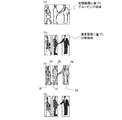
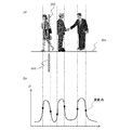
- FIG. 7 and FIG. 8 are diagrams showing an example of the result of processing according to the procedure shown in the flowchart of FIG.
- FIG. 7 shows an example in which three pedestrians stand side by side at an approximately equidistant distance from the vehicle, and the width at which the three persons are lined is the width of the preceding vehicle between vehicles of similar distance. Since the level is the same, it is a scene where erroneous grouping is easy to be performed.
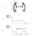
- FIG. 8 is an example in case a pedestrian is in the vicinity of a vehicle. In the case where the brake is set to be actuated earlier (from a longer distance) when the obstacle is a pedestrian than when the obstacle is a vehicle, in a scene like FIG. 8, the vehicle and the pedestrian are separated early. Failure to do so will delay the application of brakes to pedestrians.
- step S601 and step S602 gray-scale images are obtained from the images captured by the left and right cameras 101a and 101b.
- the cameras 101a and 101b have monochrome image sensors, they can acquire gray-scale images in the same image format, but if they have color image sensors, they can obtain 3 in accordance with Equations 1, 2 and 3 described above.
- the primary color signal is converted to a luminance Y signal, that is, a gray-scale format to obtain a gray-scale image.
- step S603 distance image generation unit
- step S604 grouping unit
- FIG. 7A and FIG. 8A are diagrams showing an example of the result of grouping in step S604.
- FIG. 7 (a) three pedestrians are arranged side by side at approximately the same distance and grouped into rectangular areas including these three pedestrians
- FIG. 8 (a) One pedestrian and a vehicle are arranged side by side at substantially the same distance, and are grouped into a rectangular region including the one pedestrian and the vehicle. For example, if grouping is performed as in the example illustrated in FIG. 8A, the vehicle and the pedestrian can not be separately detected, and the brake operation on the pedestrian is delayed.
- next step S 605 division unit
- division unit it is determined whether division of the area grouped as the same object based on the distance image is divisible based on the cutout of the object area based on the gray-scale image, and division is possible.
- the grouped region is divided according to the cutout of the object region based on the grayscale image.
- step S605 it is determined based on the luminance difference in the vertical direction of the grayscale image whether divisional regions can be divided, and division is performed if division is possible.
- the average luminance (average road surface luminance) at the vertical line 903 below the ground contact surface 901 of the object is determined, and the vertical line 902 above the ground contact surface 901 is obtained.
- the accumulation of the absolute value of the difference between the luminance and the road surface average luminance is calculated.
- h in Equation 7 is the apparent height (pixel) of an object (three-dimensional object) in an image.
- the vertical line for calculating the luminance difference D can be set by thinning out in the horizontal direction of the image, and the width of the vertical line can be set to one pixel or a plurality of pixels.
- the contact surface 901 is a foot position in the case of a pedestrian, and is a contact surface of a tire in a vehicle. For example, a substantially horizontal surface continuously connected to the lower end of the area grouped on the distance image is the contact surface. It can be 901.
- the area above the ground plane 901 where the difference in brightness with respect to (the road surface) is large can be estimated to be an object area (such as a pedestrian or a vehicle), and conversely, the area below the ground plane 901
- An area above the ground surface 901 where the luminance difference is small can be estimated to be an area on the extension of the road surface.
- FIG. 9 The result of performing the calculation of the luminance difference D for each vertical line of the gray image is shown in FIG.
- FIG. 9 As shown in FIG. 9 (a), it is a scene in which three pedestrians are arranged side by side, and as shown in FIG. 9 (b), in the interval portion of three pedestrians. Since the upper and lower sides sandwiching the ground contact surface 901 are both road surfaces, the difference in brightness D is reduced, while in the standing positions of the three pedestrians, the road surface below the ground contact surface 901 is the same vertical Since the pedestrian is above the ground contact surface 901 on the line, the luminance difference D is larger than when the upper and lower sides are the road surface.
- the luminance difference D becomes larger at the position of the pedestrian and becomes convex, and becomes smaller between the pedestrians and becomes concave, and the change in the luminance difference D in the lateral direction
- a vertical line passing through the inflection point in the lateral change of the luminance difference D that is, the boundary line between the area where the luminance difference D is large and the area where the luminance difference D is small, is set as the object area boundary line.
- An area in which the luminance difference D between them has a convex shape is detected as an object area (pedestrian area), and an area in which the luminance difference D between the boundary lines is concave is detected as a non-object area (road surface area) Do. Then, when a boundary line (non-object region, road surface region) based on the luminance difference D is included in the region grouped based on the distance data, it is determined that division is possible, and a non-object region extending in the vertical direction is sandwiched. Divide into left and right.
- FIG.7 (b) and FIG.8 (b) show the result of the division process in step S605.
- the area where three pedestrians are grouped together is divided by the gray image according to FIG. 7 (b).
- it is divided into three pedestrians.
- vehicle control brake control, warning control
- the division based on the gray image is performed.
- one pedestrian can be separated, and vehicle control (brake control, warning control) according to the distance can be performed on the pedestrian.
- vehicle control brake control, warning control
- the vertical line 903 below the ground plane 901 near the center of the rear surface of the preceding vehicle is set to a shadow area on the road surface, and the color of the vehicle is dark.
- the difference in luminance D between the upper and lower sides of the ground plane 901 does not increase, and it may be erroneously detected as a non-object area.
- the vertical area near the center of the rear of the preceding vehicle is detected as a non-object area, and as shown in FIG. 8B, it is divided into the left part and the right part of the rear of the preceding vehicle. The back of the car will not be detected as the same object.
- step S 606 the result of dividing the grouping area based on the distance image based on the gray image determines whether or not the same object area has been correctly cut out based on the vertical edge, and the same object area is correctly If it has not been cut out, processing is performed to merge (merge) areas that were erroneously divided.
- step S606 first, the right area and the left area are provided in each area divided in step S605, as shown in FIGS. 7C and 8C, and vertical edges included in each of the left and right areas Find the accumulation of the components.
- the right area and the left area are areas having predetermined widths set on the right and left sides respectively near the center in the width direction of each area divided in step S605.
- each area divided in step S605 includes one object, the contours of the object exist on the left and right respectively. Therefore, whether or not the contours on the left and right of the object are actually included is a vertical edge Judge based on the cumulative value of the component.
- the vertical edge included in the area near the center of the rear of the vehicle is characterized by being less near the flat bumper. Therefore, as shown in FIG. 8C, when the rear area of the preceding vehicle is erroneously divided into the left side and the right side, it is closer to the center of the left and right areas LE and RE set in the area 801 on the rear left side.
- the right region RE vertical edges are interrupted near the height of the bumper, and similarly, in the left region LE of the left and right regions LE set in the rear right region 802, the height of the bumper is There is an interruption of the vertical edge in the vicinity.
- step S 607 vehicle detection unit
- step S 607 merges adjacent areas on the side where the vertical edges were interrupted, and merges the objects in the merged area. Detect as a leading vehicle.
- step S608 divide the area based on the density image Perform object detection according to.
- FIG. 10 is a diagram for explaining an example of the merge process.
- left and right areas LE and RE are set in the areas divided by the grayscale image, and the cumulative value of the vertical edge component is calculated for each of the left and right areas LE and RE.
- FIGS. 10B and 10C show the results of projecting the accumulated values of the vertical edge components obtained in the left and right areas LE and RE, respectively, on the Y axis.
- the divided area 801 in FIG. 10A is an area including the left side surface of the preceding vehicle, and the left area LE of the divided area 801 includes the vertical edge of the left side surface of the vehicle. As such, the accumulated value of the vertical edge component exhibits a gentle change without showing a sharp drop on the way.
- the vertical edges of the bumper and the body part decrease. Show a sharp dip in the region of
- the left and right areas LE and RE it is judged in the left and right areas LE and RE whether the accumulated value of the vertical edge component falls sharply in the middle (whether or not there is a break in the vertical edge component), and a drop (break) in the vertical edge component is recognized. It is determined that the left region LE or the right region RE is not a contour portion of the vehicle, but a region closer to the center than the contour portion. In other words, if there is a drop (interruption) of the vertical edge component in one of the left and right areas LE and RE, there is an error in the division based on the gray image, and it is determined that the vehicle area is erroneously divided into left and right.
- the vehicle area can be cut out correctly, and depending on the detected vehicle It can perform forward collision warning and control the distance between vehicles.
- the grouping area based on the distance image shown in FIG. 7A is divided as shown in FIG. 7B based on the density image.
- the drop (break) of the vertical edge component does not occur in either of the left and right areas LE and RE, without merging.
- the result of division based on the density image is taken as the final object area.
- the determination of the presence or absence of the vertical edge component drop (break) can be performed using various methods, for example, the magnitude of the deviation between the left and right areas LE and RE with respect to the cumulative value of the vertical edge component.
- the determination can be made based on the cumulative value of the vertical edge component and the threshold value, or based on the differential value in the Y-axis direction (vertical direction) of the cumulative value of the vertical edge component.
- the present invention is not limited to the contents of the above-described embodiment, and various modifications can be made without departing from the spirit of the present invention.
- the example which applied the object detection apparatus and method which concern on this invention to the vehicle drive assistance system was shown in the said embodiment, it is not limited to a vehicle drive assistance system.
- various known processing methods disclosed in, for example, Japanese Patent Application Laid-Open No. 2008-065634 can be applied.
- 101 camera unit, 101a, 101b: camera, 102: image signal processing unit, 103: control unit, 104: speaker, 105: accelerator, 106: brake, 107: vehicle, 201a, 201b: CMOS, 202a, 202b: DSP , 203: CPU, 204: image processing unit 204, 205: image input I / F, 206: memory, 207: program
Landscapes
- Engineering & Computer Science (AREA)
- Physics & Mathematics (AREA)
- General Physics & Mathematics (AREA)
- Theoretical Computer Science (AREA)
- Multimedia (AREA)
- Computer Vision & Pattern Recognition (AREA)
- Human Computer Interaction (AREA)
- Traffic Control Systems (AREA)
- Image Analysis (AREA)
- Image Processing (AREA)
Abstract
La présente invention concerne la fourniture d'un dispositif de détection d'objet et un procédé de détection d'objet permettant de réduire une erreur dans un groupement basé sur une image télémétrique, une image télémétrique étant générée sur la base d'une paire d'images d'ombrage (S603), et des régions adjacentes proches dans l'image télémétrique étant groupées (S604). Dans le même temps, une différence dans les images d'ombrage est calculée entre la brillance de lignes verticales qui sont plus basses qu'une surface de base d'un objet et la brillance d'images verticales qui sont plus hautes que la surface de base de celui-ci, et sur la base de la différence de brillance, les régions groupées sont segmentées à gauche et à droite (S605). En outre, une détermination est réalisée pour décider si une rupture est présente dans les bords perpendiculaires de la région gauche ou droite de la région, la segmentation étant réalisée sur la base de l'image d'ombrage, et des régions adjacentes où la rupture du bord vertical est présente sont fusionnées (S607).
Priority Applications (2)
| Application Number | Priority Date | Filing Date | Title |
|---|---|---|---|
| US14/441,419 US9424462B2 (en) | 2012-11-08 | 2013-10-11 | Object detection device and object detection method |
| EP13854008.3A EP2919197B1 (fr) | 2012-11-08 | 2013-10-11 | Dispositif de détection d'objet et procédé de détection d'objet |
Applications Claiming Priority (2)
| Application Number | Priority Date | Filing Date | Title |
|---|---|---|---|
| JP2012246693A JP6013884B2 (ja) | 2012-11-08 | 2012-11-08 | 物体検出装置及び物体検出方法 |
| JP2012-246693 | 2012-11-08 |
Publications (1)
| Publication Number | Publication Date |
|---|---|
| WO2014073322A1 true WO2014073322A1 (fr) | 2014-05-15 |
Family
ID=50684436
Family Applications (1)
| Application Number | Title | Priority Date | Filing Date |
|---|---|---|---|
| PCT/JP2013/077694 WO2014073322A1 (fr) | 2012-11-08 | 2013-10-11 | Dispositif de détection d'objet et procédé de détection d'objet |
Country Status (4)
| Country | Link |
|---|---|
| US (1) | US9424462B2 (fr) |
| EP (1) | EP2919197B1 (fr) |
| JP (1) | JP6013884B2 (fr) |
| WO (1) | WO2014073322A1 (fr) |
Cited By (5)
| Publication number | Priority date | Publication date | Assignee | Title |
|---|---|---|---|---|
| WO2017098709A1 (fr) * | 2015-12-08 | 2017-06-15 | パナソニックIpマネジメント株式会社 | Dispositif de reconnaissance d'images et procédé de reconnaissance d'images |
| CN107533749A (zh) * | 2015-06-30 | 2018-01-02 | 日立汽车系统株式会社 | 物体检测装置 |
| EP3258214A4 (fr) * | 2015-02-12 | 2019-03-13 | Hitachi Automotive Systems, Ltd. | Dispositif de détection d'objet |
| WO2019203000A1 (fr) * | 2018-04-17 | 2019-10-24 | 日立オートモティブシステムズ株式会社 | Dispositif de reconnaissance d'environnement externe |
| CN115272341A (zh) * | 2022-09-29 | 2022-11-01 | 华联机械集团有限公司 | 一种基于机器视觉的包装机缺陷产品检测方法 |
Families Citing this family (27)
| Publication number | Priority date | Publication date | Assignee | Title |
|---|---|---|---|---|
| JP6313667B2 (ja) * | 2014-06-10 | 2018-04-18 | 株式会社Subaru | 車外環境認識装置 |
| JP6407626B2 (ja) * | 2014-08-26 | 2018-10-17 | 日立オートモティブシステムズ株式会社 | 物体認識装置及び車両制御システム |
| JP6591188B2 (ja) * | 2015-03-30 | 2019-10-16 | 株式会社Subaru | 車外環境認識装置 |
| JP6614822B2 (ja) * | 2015-06-22 | 2019-12-04 | キヤノン株式会社 | 画像符号化装置及びその制御方法及びプログラム及び記憶媒体 |
| JP6592991B2 (ja) | 2015-07-06 | 2019-10-23 | 株式会社リコー | 物体検出装置、物体検出方法及びプログラム |
| EP3115933B1 (fr) | 2015-07-07 | 2021-03-17 | Ricoh Company, Ltd. | Dispositif de traitement d'images, dispositif de capture d'images, système de commande de corps mobile, procédé de traitement d'images et support d'enregistrement lisible sur ordinateur |
| JP6606369B2 (ja) * | 2015-07-21 | 2019-11-13 | 株式会社Soken | 物体検出装置及び物体検出方法 |
| CN105678268B (zh) * | 2016-01-11 | 2020-06-30 | 华东理工大学 | 一种基于双区域学习的地铁站场景行人计数实现方法 |
| JP6752024B2 (ja) * | 2016-02-12 | 2020-09-09 | 日立オートモティブシステムズ株式会社 | 画像処理装置 |
| JP6786279B2 (ja) * | 2016-07-05 | 2020-11-18 | 日立オートモティブシステムズ株式会社 | 画像処理装置 |
| EP3324336A1 (fr) | 2016-11-18 | 2018-05-23 | Ricoh Company Ltd. | Dispositif et procédé de traitement d'informations et moyens de support |
| JP6782433B2 (ja) * | 2017-03-22 | 2020-11-11 | パナソニックIpマネジメント株式会社 | 画像認識装置 |
| WO2019161300A1 (fr) | 2018-02-18 | 2019-08-22 | Nvidia Corporation | Détection d'objets et détermination de scores de confiance |
| WO2019168869A1 (fr) | 2018-02-27 | 2019-09-06 | Nvidia Corporation | Détection en temps réel de voies et de limites par des véhicules autonomes |
| WO2019178548A1 (fr) | 2018-03-15 | 2019-09-19 | Nvidia Corporation | Détermination d'emplacements de stationnement manoeuvrables pour véhicules autonomes |
| US11182916B2 (en) * | 2018-12-28 | 2021-11-23 | Nvidia Corporation | Distance to obstacle detection in autonomous machine applications |
| US11170299B2 (en) | 2018-12-28 | 2021-11-09 | Nvidia Corporation | Distance estimation to objects and free-space boundaries in autonomous machine applications |
| DE112019006484T5 (de) | 2018-12-28 | 2021-10-21 | Nvidia Corporation | Detektion von abständen zu hindernissen in autonomen maschinenanwendungen |
| WO2020185779A1 (fr) | 2019-03-11 | 2020-09-17 | Nvidia Corporation | Détection et classification d'intersection dans des applications de machine autonome |
| KR102083126B1 (ko) * | 2019-08-05 | 2020-02-28 | 이정숙 | 진공 흡착구 |
| JP2022546397A (ja) | 2019-08-31 | 2022-11-04 | エヌビディア コーポレーション | 自律運転アプリケーションのためのマップ作成及びローカリゼーション |
| JP7406962B2 (ja) * | 2019-11-26 | 2023-12-28 | 株式会社Subaru | 画像処理装置 |
| US11978266B2 (en) | 2020-10-21 | 2024-05-07 | Nvidia Corporation | Occupant attentiveness and cognitive load monitoring for autonomous and semi-autonomous driving applications |
| CN112241717B (zh) * | 2020-10-23 | 2021-11-16 | 北京嘀嘀无限科技发展有限公司 | 前车检测方法、前车检测模型的训练获取方法及装置 |
| US11461992B2 (en) | 2020-11-12 | 2022-10-04 | Samsung Electronics Co., Ltd. | Region of interest selection for object detection |
| WO2023157621A1 (fr) * | 2022-02-15 | 2023-08-24 | ソニーグループ株式会社 | Dispositif de traitement d'informations et procédé de traitement d'informations |
| CN117115816B (zh) * | 2023-10-24 | 2024-02-09 | 深圳市美侨医疗科技有限公司 | 一种白带显微图像中线索细胞的识别方法及系统 |
Citations (4)
| Publication number | Priority date | Publication date | Assignee | Title |
|---|---|---|---|---|
| JP2001052171A (ja) * | 1999-08-06 | 2001-02-23 | Nissan Motor Co Ltd | 周囲環境認識装置 |
| JP2002183737A (ja) * | 2000-12-18 | 2002-06-28 | Honda Motor Co Ltd | 対象物認識装置 |
| JP2008065634A (ja) | 2006-09-07 | 2008-03-21 | Fuji Heavy Ind Ltd | 物体検出装置および物体検出方法 |
| JP2009139324A (ja) * | 2007-12-10 | 2009-06-25 | Mazda Motor Corp | 車両用走行路面検出装置 |
Family Cites Families (8)
| Publication number | Priority date | Publication date | Assignee | Title |
|---|---|---|---|---|
| JPH07225127A (ja) * | 1994-02-14 | 1995-08-22 | Mitsubishi Motors Corp | 車両用路上物体認識装置 |
| JP4990806B2 (ja) * | 2008-01-22 | 2012-08-01 | 富士重工業株式会社 | 撮像手段の調整装置および車外監視装置 |
| JP4482599B2 (ja) * | 2008-10-24 | 2010-06-16 | 本田技研工業株式会社 | 車両の周辺監視装置 |
| JP5188430B2 (ja) * | 2009-03-24 | 2013-04-24 | 富士重工業株式会社 | 画像処理装置 |
| WO2011078199A1 (fr) * | 2009-12-25 | 2011-06-30 | Ricoh Company, Ltd. | Appareil d'identification d'objets, appareil de commande de corps en mouvement et appareil de présentation d'informations |
| JP5665401B2 (ja) * | 2010-07-21 | 2015-02-04 | キヤノン株式会社 | 画像処理装置、画像処理方法及びプログラム |
| WO2012014430A1 (fr) * | 2010-07-27 | 2012-02-02 | パナソニック株式会社 | Dispositif de détection de corps mobile et procédé de détection de corps mobile |
| JP5580233B2 (ja) * | 2011-03-22 | 2014-08-27 | 富士重工業株式会社 | 車外監視装置および車外監視方法 |
-
2012
- 2012-11-08 JP JP2012246693A patent/JP6013884B2/ja active Active
-
2013
- 2013-10-11 WO PCT/JP2013/077694 patent/WO2014073322A1/fr active Application Filing
- 2013-10-11 US US14/441,419 patent/US9424462B2/en active Active
- 2013-10-11 EP EP13854008.3A patent/EP2919197B1/fr active Active
Patent Citations (4)
| Publication number | Priority date | Publication date | Assignee | Title |
|---|---|---|---|---|
| JP2001052171A (ja) * | 1999-08-06 | 2001-02-23 | Nissan Motor Co Ltd | 周囲環境認識装置 |
| JP2002183737A (ja) * | 2000-12-18 | 2002-06-28 | Honda Motor Co Ltd | 対象物認識装置 |
| JP2008065634A (ja) | 2006-09-07 | 2008-03-21 | Fuji Heavy Ind Ltd | 物体検出装置および物体検出方法 |
| JP2009139324A (ja) * | 2007-12-10 | 2009-06-25 | Mazda Motor Corp | 車両用走行路面検出装置 |
Cited By (14)
| Publication number | Priority date | Publication date | Assignee | Title |
|---|---|---|---|---|
| EP3258214A4 (fr) * | 2015-02-12 | 2019-03-13 | Hitachi Automotive Systems, Ltd. | Dispositif de détection d'objet |
| US10627228B2 (en) | 2015-02-12 | 2020-04-21 | Hitachi Automotive Systems, Ltd. | Object detection device |
| EP3319037A4 (fr) * | 2015-06-30 | 2019-02-27 | Hitachi Automotive Systems, Ltd. | Dispositif de détection d'objet |
| US10360436B2 (en) | 2015-06-30 | 2019-07-23 | Hitachi Automotive Systems, Ltd. | Object detection device |
| CN107533749A (zh) * | 2015-06-30 | 2018-01-02 | 日立汽车系统株式会社 | 物体检测装置 |
| CN107533749B (zh) * | 2015-06-30 | 2020-12-22 | 日立汽车系统株式会社 | 物体检测装置 |
| WO2017098709A1 (fr) * | 2015-12-08 | 2017-06-15 | パナソニックIpマネジメント株式会社 | Dispositif de reconnaissance d'images et procédé de reconnaissance d'images |
| JPWO2017098709A1 (ja) * | 2015-12-08 | 2018-04-05 | パナソニックIpマネジメント株式会社 | 画像認識装置および画像認識方法 |
| US10339405B2 (en) | 2015-12-08 | 2019-07-02 | Panasonic Intellectual Property Management Co., Ltd. | Image recognition device and image recognition method |
| WO2019203000A1 (fr) * | 2018-04-17 | 2019-10-24 | 日立オートモティブシステムズ株式会社 | Dispositif de reconnaissance d'environnement externe |
| JP2019185666A (ja) * | 2018-04-17 | 2019-10-24 | 日立オートモティブシステムズ株式会社 | 外界認識装置 |
| CN111937035A (zh) * | 2018-04-17 | 2020-11-13 | 日立汽车系统株式会社 | 外界识别装置 |
| JP7106332B2 (ja) | 2018-04-17 | 2022-07-26 | 日立Astemo株式会社 | 外界認識装置 |
| CN115272341A (zh) * | 2022-09-29 | 2022-11-01 | 华联机械集团有限公司 | 一种基于机器视觉的包装机缺陷产品检测方法 |
Also Published As
| Publication number | Publication date |
|---|---|
| US9424462B2 (en) | 2016-08-23 |
| EP2919197A1 (fr) | 2015-09-16 |
| EP2919197A4 (fr) | 2016-11-09 |
| JP2014096005A (ja) | 2014-05-22 |
| JP6013884B2 (ja) | 2016-10-25 |
| EP2919197B1 (fr) | 2020-07-29 |
| US20150278578A1 (en) | 2015-10-01 |
Similar Documents
| Publication | Publication Date | Title |
|---|---|---|
| WO2014073322A1 (fr) | Dispositif de détection d'objet et procédé de détection d'objet | |
| JP5863536B2 (ja) | 車外監視装置 | |
| JP5926228B2 (ja) | 自律車両用の奥行き検知方法及びシステム | |
| JP2018179911A (ja) | 測距装置及び距離情報取得方法 | |
| WO2012120856A1 (fr) | Dispositif et procédé de détection d'objets | |
| JP5068134B2 (ja) | 対象領域分割方法及び対象領域分割装置 | |
| US10719949B2 (en) | Method and apparatus for monitoring region around vehicle | |
| JP6743882B2 (ja) | 画像処理装置、機器制御システム、撮像装置、画像処理方法及びプログラム | |
| JP6592991B2 (ja) | 物体検出装置、物体検出方法及びプログラム | |
| JP6544257B2 (ja) | 情報処理システム、情報処理方法及び情報処理プログラム | |
| KR20060021922A (ko) | 두 개의 카메라를 이용한 장애물 감지 기술 및 장치 | |
| JP2018060422A (ja) | 物体検出装置 | |
| KR101818842B1 (ko) | 운전지원장치, 거리감지방법 및 차로의 너비감지방법 | |
| KR101402089B1 (ko) | 장애물 검출 장치 및 방법 | |
| WO2011016257A1 (fr) | Dispositif de calcul de la distance pour un véhicule | |
| JP2013161190A (ja) | 物体認識装置 | |
| JP3868915B2 (ja) | 前方監視装置及びその方法 | |
| JP2010224936A (ja) | 物体検出装置 | |
| JP5587852B2 (ja) | 画像処理装置及び画像処理方法 | |
| US20200210730A1 (en) | Vehicle exterior environment recognition apparatus | |
| JP2010231400A (ja) | 障害物危険度算出装置、方法及びプログラム | |
| JP2007195061A (ja) | 画像処理装置 | |
| JPWO2017090097A1 (ja) | 車両用外界認識装置 | |
| JP2020126304A (ja) | 車外物体検出装置 | |
| JP6988860B2 (ja) | 情報処理システム、情報処理方法及び情報処理プログラム |
Legal Events
| Date | Code | Title | Description |
|---|---|---|---|
| 121 | Ep: the epo has been informed by wipo that ep was designated in this application |
Ref document number: 13854008 Country of ref document: EP Kind code of ref document: A1 |
|
| WWE | Wipo information: entry into national phase |
Ref document number: 2013854008 Country of ref document: EP |
|
| WWE | Wipo information: entry into national phase |
Ref document number: 14441419 Country of ref document: US |
|
| NENP | Non-entry into the national phase |
Ref country code: DE |