WO2014069417A1 - 船舶用原動機装置及びこれを備えた船舶 - Google Patents
船舶用原動機装置及びこれを備えた船舶 Download PDFInfo
- Publication number
- WO2014069417A1 WO2014069417A1 PCT/JP2013/079169 JP2013079169W WO2014069417A1 WO 2014069417 A1 WO2014069417 A1 WO 2014069417A1 JP 2013079169 W JP2013079169 W JP 2013079169W WO 2014069417 A1 WO2014069417 A1 WO 2014069417A1
- Authority
- WO
- WIPO (PCT)
- Prior art keywords
- engine
- propulsion
- shaft
- diesel engine
- power
- Prior art date
- Legal status (The legal status is an assumption and is not a legal conclusion. Google has not performed a legal analysis and makes no representation as to the accuracy of the status listed.)
- Ceased
Links
Images




Classifications
-
- B—PERFORMING OPERATIONS; TRANSPORTING
- B63—SHIPS OR OTHER WATERBORNE VESSELS; RELATED EQUIPMENT
- B63H—MARINE PROPULSION OR STEERING
- B63H5/00—Arrangements on vessels of propulsion elements directly acting on water
- B63H5/07—Arrangements on vessels of propulsion elements directly acting on water of propellers
- B63H5/08—Arrangements on vessels of propulsion elements directly acting on water of propellers of more than one propeller
-
- B—PERFORMING OPERATIONS; TRANSPORTING
- B63—SHIPS OR OTHER WATERBORNE VESSELS; RELATED EQUIPMENT
- B63H—MARINE PROPULSION OR STEERING
- B63H21/00—Use of propulsion power plant or units on vessels
- B63H21/12—Use of propulsion power plant or units on vessels the vessels being motor-driven
- B63H21/14—Use of propulsion power plant or units on vessels the vessels being motor-driven relating to internal-combustion engines
-
- B—PERFORMING OPERATIONS; TRANSPORTING
- B63—SHIPS OR OTHER WATERBORNE VESSELS; RELATED EQUIPMENT
- B63H—MARINE PROPULSION OR STEERING
- B63H21/00—Use of propulsion power plant or units on vessels
- B63H21/32—Arrangements of propulsion power-unit exhaust uptakes; Funnels peculiar to vessels
-
- B—PERFORMING OPERATIONS; TRANSPORTING
- B63—SHIPS OR OTHER WATERBORNE VESSELS; RELATED EQUIPMENT
- B63H—MARINE PROPULSION OR STEERING
- B63H23/00—Transmitting power from propulsion power plant to propulsive elements
- B63H23/02—Transmitting power from propulsion power plant to propulsive elements with mechanical gearing
- B63H23/06—Transmitting power from propulsion power plant to propulsive elements with mechanical gearing for transmitting drive from a single propulsion power unit
-
- B—PERFORMING OPERATIONS; TRANSPORTING
- B63—SHIPS OR OTHER WATERBORNE VESSELS; RELATED EQUIPMENT
- B63J—AUXILIARIES ON VESSELS
- B63J3/00—Driving of auxiliaries
- B63J3/02—Driving of auxiliaries from propulsion power plant
-
- Y—GENERAL TAGGING OF NEW TECHNOLOGICAL DEVELOPMENTS; GENERAL TAGGING OF CROSS-SECTIONAL TECHNOLOGIES SPANNING OVER SEVERAL SECTIONS OF THE IPC; TECHNICAL SUBJECTS COVERED BY FORMER USPC CROSS-REFERENCE ART COLLECTIONS [XRACs] AND DIGESTS
- Y02—TECHNOLOGIES OR APPLICATIONS FOR MITIGATION OR ADAPTATION AGAINST CLIMATE CHANGE
- Y02T—CLIMATE CHANGE MITIGATION TECHNOLOGIES RELATED TO TRANSPORTATION
- Y02T70/00—Maritime or waterways transport
- Y02T70/50—Measures to reduce greenhouse gas emissions related to the propulsion system
Definitions
- the present invention relates to a marine motor device and a marine vessel equipped with the same.
- a single low-speed two-stroke diesel engine is installed as the main engine to drive the propeller for propulsion, and propulsion is performed in a single-shaft system.
- a configuration is employed.
- a plurality of (for example, about three) medium-speed four-stroke diesel engines that are driven at a constant speed are mounted as auxiliary engines that operate shaft-driven generators that supply power to the electrical system in the ship.
- These diesel engine groups are arranged in an engine room on the stern side of the ship.
- Patent Documents 1 and 2 disclose a two-unit two-shaft type ship equipped with two main engines (diesel engines) and rotationally driving two propellers.
- the propulsion efficiency of the propeller can be improved in the prior art configurations shown in Patent Documents 1 and 2, compared with the conventional one-shaft / one-shaft method, the two main engines (diesel engines) rotate two propellers. Since it is dedicated for driving, an auxiliary engine for operating the shaft-driven generator must be provided separately, which makes it difficult to reduce the size of the engine room, and consequently, it is difficult to expand the cargo room of the ship.
- the structure where power is supplied to the ship using a generator driven by the main engine it is stipulated in the classification rules that power supply can be automatically restored when power supply is stopped due to a failure of the main engine or the generator. It has been.
- the conventional ship is equipped with a standby generator that is independent from the generator driven by the main engine, and automatically activates the standby generator when the generator is stopped to establish the frequency and voltage. The power supply was restored.
- a separate standby generator is required in addition to the normally used generator, the structure becomes complicated and the manufacturing cost increases.
- the invention according to claim 1 relates to a marine prime mover device, and generates power using a diesel engine, a speed reducer that transmits power of the diesel engine to a propulsion shaft that rotationally drives a propeller for marine propulsion, and power of the diesel engine.
- a pair of propulsion and power generation mechanisms combined with a shaft-driven generator is provided, and the pair of propulsion and power generation mechanisms are arranged in the engine room in the hull so as to be distributed to the left and right across the hull center line. is there.
- the marine engine apparatus according to the first aspect, wherein in each of the propulsion and power generation mechanisms, the speed reducer and the shaft drive generator are disposed closer to the bow than the diesel engine,
- the propulsion shaft is disposed on the left and right outside of the diesel engine and in a state of being eccentric in the vertical direction with respect to the output shaft of the diesel engine.
- the marine engine apparatus wherein the propulsion and power generation mechanisms are arranged in the order of the shaft drive generator, the speed reducer, and the diesel engine from the bow side toward the stern side. They are arranged side by side.
- the marine engine apparatus according to the first aspect, wherein in each of the propulsion and power generation mechanisms, the speed reducer and the shaft drive generator are disposed on the stern side of the diesel engine,
- the propulsion shaft is coaxial with the output shaft of the diesel engine in a plan view and is disposed in a state of being eccentric in the vertical direction with respect to the output shaft of the diesel engine.
- the marine engine apparatus wherein the propulsion and power generation mechanisms are arranged in the order of the diesel engine, the speed reducer, and the shaft drive generator from the bow side toward the stern side. They are arranged side by side.
- a marine engine apparatus according to any one of the first to fifth aspects, wherein an exhaust gas purifying device that purifies exhaust gas from the two diesel engines is disposed on the upper side of the engine room. And exhaust gas that has passed through the exhaust gas purifying device is discharged from a funnel in the upper part of the hull.
- the invention of claim 7 relates to a ship, wherein the marine motor device according to any one of claims 1 to 6 is mounted.
- a diesel engine a speed reducer that transmits the power of the diesel engine to a propulsion shaft that rotationally drives a propeller for marine propulsion, and a shaft drive generator that generates power using the power of the diesel engine are combined.
- a pair of propulsion and power generation mechanisms are provided, and the pair of propulsion and power generation mechanisms are arranged in the engine room in the hull so as to be distributed to the left and right across the hull center line, so that a plurality of diesel engines (the main engine and Compared to the conventional structure in which the auxiliary engine is disposed in the engine room, the engine installation space in the engine room can be reduced.
- the engine room can be configured compactly by shortening the longitudinal length of the engine room, and as a result, it is easy to secure a hold space (a space other than the engine room) of the hull.
- the propulsion efficiency of the ship can be improved by driving the two propellers. Since each of the diesel engines can drive the propeller and the shaft-driven generator, the number of the diesel engines can be reduced to only two as compared with the conventional structure. Accordingly, maintenance costs and component replacement costs can be reduced.
- each of the diesel engines can rotate the propeller and drive the shaft-driven generator, so that one of the shaft-driven generators can be reserved during normal navigation. Therefore, for example, when power supply is stopped due to a failure of one diesel engine or the shaft drive generator, the other shaft drive generator can be started and the frequency and voltage can be established to restore power supply. That's fine.
- the speed reducer and the shaft drive generator are disposed on the bow side of the diesel engine, and the propulsion shaft is disposed on the left and right outer sides of the diesel engine. Therefore, after ensuring the installation balance of the both propulsion and power generation mechanisms in the ship, it is possible to reliably ensure the left-right arrangement interval between the two propulsion shafts, and thus the left-right arrangement interval between the two propellers. Further, since the propulsion shaft is arranged in a state of being eccentric in the vertical direction with respect to the output shaft of the diesel engine, it is possible to prevent the propulsion shaft from covering and closing the side surface of the diesel engine, Maintenance workability can be improved.
- each propulsion and power generation mechanism is configured by arranging the shaft drive generator, the speed reducer, and the diesel engine in this order from the bow side toward the stern side.
- the machine and the propulsion shaft are distributed back and forth across the speed reducer and do not interfere with each other. Therefore, a compact arrangement of each propulsion and power generation mechanism is possible.
- the speed reducer and the shaft drive generator are disposed on the stern side of the diesel engine, and the propulsion shaft is connected to an output shaft of the diesel engine. Since it is coaxial in a plan view and is arranged in a state of being eccentric in the vertical direction with respect to the output shaft of the diesel engine, for example, the speed reducer and the shaft drive in or near the skeg on the stern side It is possible to arrange the generator and arrange the diesel engine on the stern side as much as possible regardless of the restrictions of the ship's badock line. For this reason, it is effective for making the engine room compact.
- each propulsion and power generation mechanism is configured by arranging the diesel engine, the speed reducer, and the shaft drive generator in this order from the bow side toward the stern side.
- the machine and the propulsion shaft are distributed up and down and do not interfere with each other. Therefore, also in this case, a compact arrangement of the propulsion and power generation mechanisms is possible.
- an exhaust gas purification device that purifies exhaust gas from the two diesel engines is provided on the upper side of the engine room, and the exhaust gas that has passed through the exhaust gas purification device is supplied to the hull. Since it is configured to discharge from the upper funnel, the space formed in the upper part of the engine room by reducing the engine installation space can be effectively used as the installation location of the exhaust gas purification device.
- the exhaust gas purification device can be easily installed without enlarging the engine room.
- the exhaust gas purification device can be functionally assembled between the diesel engine located on the bottom side of the hull and the funnel at the top of the hull without increasing the exhaust resistance of the exhaust gas from the diesel engine, Purification performance can be improved.
- the ship 1 of the first embodiment includes a hull 2, a cabin 3 (bridge) provided on the stern side of the hull 2, and a funnel 4 ( A chimney) and a pair of propellers 5 and a rudder 6 provided at the lower rear of the hull 2.
- a pair of skegs 8 are integrally formed on the stern side bottom 7.
- a propeller shaft 9 that rotates the propeller 5 is supported on each skeg 8.
- Each skeg 8 is formed symmetrically with respect to a hull center line CL (see FIG. 3) that divides the hull 2 in the left-right width direction. That is, in the first embodiment, twin skeg is adopted as the stern shape of the hull 2.
- a hull 10 is provided on the bow side and the center of the hull 2, and an engine room 11 is provided on the stern side of the hull 2.
- a pair of propulsion and power generation mechanisms 12, which serve both as a drive source for the propeller 5 and a power supply source for the ship 1, are distributed to the left and right across the hull center line CL.
- Each propeller 5 is rotationally driven by the rotational power transmitted from each propulsion and power generation mechanism 12 to the propulsion shaft 9.
- the interior of the engine room 11 is partitioned vertically by an upper deck 13, a second deck 14, a third deck 15 and an inner bottom plate 16.
- Each propulsion and power generation mechanism 12 of the first embodiment is installed on the inner bottom plate 16 at the lowest stage of the engine room 11.
- the hold 10 is divided into a plurality of sections.
- each propulsion and power generation mechanism 12 includes a medium-speed four-stroke diesel engine 21 (hereinafter simply referred to as an engine), a speed reducer 22 that transmits the power of the engine 21 to the propulsion shaft 9, and A shaft drive generator 23 that generates power using the power of the engine 21 is combined.
- the “medium speed” engine means one that is driven at a rotational speed of about 500 to 1000 revolutions per minute.
- a “low speed” engine is driven at a rotational speed of 500 revolutions per minute
- a “high speed” engine is driven at a rotational speed of 1000 revolutions per minute.
- the engine 21 of the first embodiment is configured to be driven at a constant speed within a medium speed range (about 700 to 750 revolutions per minute).
- the engine 21 includes a cylinder block 25 having an engine output shaft 24 (crankshaft) and a cylinder head 26 mounted on the cylinder block 25.
- a base stand 27 is installed directly or via a vibration isolator (not shown).
- a cylinder block 25 of the engine 21 is mounted on the base table 27.
- the engine output shaft 24 extends in a direction along the longitudinal direction of the hull 2. That is, the engine 21 is disposed in the engine room 11 with the direction of the engine output shaft 24 being along the longitudinal direction of the hull 2.
- the reduction gear 22 and the shaft drive generator 23 are arranged on the bow side of the engine 21.
- the front end side of the engine output shaft 24 protrudes from the front side of the engine 21.
- the speed reducer 22 is connected to the front end side so that power can be transmitted.
- a shaft drive generator 23 is disposed on the opposite side of the engine 21 with the speed reducer 22 in between.
- the shaft drive generator 23, the speed reducer 22, and the engine 21 are arranged in this order from the front in the engine room 11.
- the propulsion shaft 9 is provided on the power transmission downstream side of the speed reducer 22.
- the constant speed power of the engine 21 is branched and transmitted from the front end side of the engine output shaft 24 to the shaft drive generator 23 and the propulsion shaft 9 via the speed reducer 22.
- a part of the constant speed power of the engine 21 is decelerated to a rotational speed of, for example, about 100 to 120 revolutions per minute by the speed reducer 22 and transmitted to the propulsion shaft 9.
- the propeller 5 is rotationally driven by the deceleration power from the speed reducer 22.
- the propeller 5 of the first embodiment employs a variable pitch propeller that can adjust the ship speed by changing the blade angle of the propeller blades.
- a part of the constant speed power of the engine 21 is increased to a rotational speed of, for example, about 1200 or 1800 revolutions per minute by the speed reducer 22 and transmitted to the PTO shaft 42 rotatably supported by the speed reducer 22. Is done.
- the front end side of the PTO shaft 42 is coupled to the shaft drive generator 23 so that power can be transmitted.
- the rotational power of the PTO shaft 42 drives the shaft-driven generator 23 to generate power.
- the generated power generated by driving the shaft drive generator 23 is supplied to the electrical system in the hull 2.
- the front end side of the engine output shaft 24 is connected to the speed reducer input shaft 41 (see FIG. 5) of the speed reducer 22.
- the reduction gear input shaft 41 is rotatably supported in the reduction gear 22.
- a PTO shaft 42 that transmits power to the shaft drive generator 23
- a speed reducer output shaft 44 that transmits power to the propulsion shaft 9
- a relay shaft 43 are rotatable in parallel with the speed reducer input shaft 41. It is pivotally supported.
- the input gear 45 fixed to the reduction gear input shaft 41 is engaged with a PTO gear 46 fixed to the PTO shaft 42 and a first relay gear 47 fixed to the relay shaft 43.
- a second relay gear 48 is also fixed to the relay shaft 43.
- the second relay gear 48 of the relay shaft 43 is meshed with an output gear 49 fixed to the reduction gear output shaft 44.
- the outer shape of the speed reducer 22 projects outward from the engine 21 and the shaft drive generator 23 to the left and right.
- the front end side of the propulsion shaft 9 is connected to the rear surface side of the overhanging portion so that power can be transmitted.
- the rear side of the propulsion shaft 9 passes through a skeg 8 formed integrally with the ship bottom 7.
- a propeller 5 is attached to the rear end portion of the propulsion shaft 9. Therefore, the propulsion shaft 9 is located on the left and right outside of the engine 21. In other words, in the plan view, the propulsion shaft 9 is located on the opposite side of the hull center line CL across the engine 21.
- the engine output shaft 24 (shaft core line) and the propulsion shaft 9 extend in parallel to each other.
- the propulsion shaft 9 extends in the longitudinal direction of the hull 2 in a state of being eccentric in the vertical direction with respect to the engine output shaft 24 (axial core line). In this case, the propulsion shaft 9 is placed at a position lower than the engine output shaft 24 (axial core line) and close to the inner bottom plate 16 so as not to cover the side surface of the cylinder block 25 facing the propulsion shaft 9 as much as possible. Yes.
- the engine 21 is connected to an intake path (not shown) for air intake and an exhaust path 28 for exhaust gas discharge.
- the air taken in through the intake path is sent into each cylinder of the engine 21 (inside the cylinder in the intake stroke).
- the fuel drawn from the fuel tank is pumped into the combustion chamber of each cylinder by the fuel injection device, so that the expansion stroke accompanying the self-ignition combustion of the air-fuel mixture is performed in each combustion chamber. .
- each exhaust path 28 is connected to an extended path 29.
- the extension path 29 extends to the funnel 4 and is configured to communicate directly with the outside.
- a post-treatment device 30 is provided as an exhaust gas purification device that mainly performs exhaust gas purification processing (NOx reduction processing). Exhaust gas from each engine 21 is subjected to purification treatment via each exhaust path 28, extension path 29, and aftertreatment device 30, and then released to the outside of the ship 1.
- the post-processing device 30 is disposed on the upper side of the engine room 11. In the first embodiment, the post-processing device 30 is installed on the third deck 15 in the middle of the engine room 11.
- a urea water injection nozzle 31 that supplies a urea aqueous solution (hereinafter referred to as urea water), which is a reducing agent for NOx reduction, to the exhaust gas in the extension path 29 on the upstream side of the post-treatment device 30 in the extension path 29.
- urea water a urea aqueous solution
- one post-processing device 30 is provided for one propulsion and power generation mechanism 12 (which may be referred to as the engine 21).
- the exhaust paths 28 may be merged into one collective path, the collective path may be extended to the funnel 4, and the post-processing device 30 may be provided in the middle of the collective path.
- the post-treatment device 30 was supplied in excess from a NOx catalyst 33 for promoting the reduction of NOx in the exhaust gas in an order from the upstream side in a post-treatment casing 32 made of a heat-resistant metal material formed in a substantially cylindrical shape.
- the slip treatment catalyst 34 that promotes the oxidation treatment of the reducing agent (in this case, ammonia after hydrolysis) and the silencer 35 that attenuates the exhaust noise of the exhaust gas are accommodated in series.
- Each catalyst 33, 34 has a honeycomb structure composed of a large number of cells partitioned by porous (filterable) partition walls, and has a catalytic metal such as alumina, zirconia, vanadia / titania or zeolite. is doing.
- the NOx catalyst 33 exhaust gas sent into the aftertreatment device 30 by selectively reducing NOx in the exhaust gas using ammonia generated by hydrolysis of urea water from the urea water injection nozzle 31 as a reducing agent. Is to purify.
- the slip treatment catalyst 34 oxidizes unreacted (surplus) ammonia flowing out from the NOx catalyst 33 to harmless nitrogen.
- the exhaust gas discharged from each engine 21 enters the aftertreatment casing 32 and passes through the NOx catalyst 33 and the slip treatment catalyst 34 to be purified. Then, the exhaust gas after the purification process is discharged out of the post-processing casing 32 and eventually out of the ship 1 through the silencer 35.
- the NOx catalyst 33 and the slip treatment catalyst 34 By accommodating the NOx catalyst 33 and the slip treatment catalyst 34 in the post-treatment casing 32, the excess reducing agent (ammonia) that tries to pass through the NOx catalyst 33 unreacted can be oxidized and rendered harmless by nitrogen. Therefore, it is possible to reliably avoid the possibility that ammonia remains in the exhaust gas. Further, the NOx catalyst 33 and the slip treatment catalyst 34 can be packaged, and the downstream side of the exhaust structure can be made compact. Since the aftertreatment casing 32 includes the silencer 35, the NOx catalyst 33, the slip treatment catalyst 34, and the silencer 35 can be packaged in a single aftertreatment casing 32, and the downstream side of the exhaust structure can be configured compactly. .
- the engine room 11 can be configured compactly by shortening the longitudinal length of the engine room 11, and as a result, it is easy to secure a hold space (a space other than the engine room 11) in the hull 2.
- the propulsion efficiency of the ship 1 can be improved by driving the two propellers 5. Since each of the diesel engines 21 can drive the propeller 5 and the shaft-driven generator 23, the number of the diesel engines 21 can be reduced to only two as compared with the conventional structure. Accordingly, maintenance costs and component replacement costs can be reduced.
- each diesel engine 21 can rotate the propeller 5 and drive the shaft-driven generator 23, so that one of the shaft-driven generators 23 is reserved for normal navigation. Can be. Therefore, for example, when the power supply is stopped due to a failure of one diesel engine 21 or the shaft drive generator 23, the other shaft drive generator 23 is started, and the frequency and voltage are established to supply power. It only has to be restored.
- the diesel engine 21 is stopped at the time of navigation with only one diesel engine 21, the other diesel engine 21 that is stopped, and thus the shaft-driven generator 23 corresponding thereto, is started. Then, the frequency and voltage may be established and power feeding may be restored. That is, even if the conventional standby generator is not provided separately, the classification rules can be satisfied and the manufacturing cost is advantageous.
- each propulsion and power generation mechanism 12 the speed reducer 22 and the shaft drive generator 23 are disposed on the bow side of the diesel engine 21, and the propulsion shaft 9 is disposed on the left and right outer sides of the diesel engine 21. Therefore, after securing the installation balance of the both propulsion and power generation mechanisms 12 in the ship 1, it is possible to reliably ensure the left-right arrangement interval between the two propulsion shafts 9 and thus the left-right arrangement interval between the two propellers 5. .
- the propulsion shaft 9 is arranged in a state of being eccentric in the vertical direction with respect to the engine output shaft 24 of the diesel engine 21, the side surface of the diesel engine 21 is covered with the propulsion shaft 9 and blocked. The maintenance workability inside the diesel engine 21 can be improved.
- each propulsion and power generation mechanism 12 is configured by arranging the shaft drive generator 23, the speed reducer 22, and the diesel engine 21 in this order from the bow side toward the stern side. And the propulsion shaft 9 are distributed back and forth across the reduction gear 22 and do not interfere with each other. Therefore, a compact arrangement of each propulsion and power generation mechanism 12 is possible.
- an exhaust gas purifying device 30 that purifies exhaust gas from both diesel engines 21 is provided on the upper side of the engine room 11, and the exhaust gas that has passed through the exhaust gas purifying device 30 is removed. Since it is configured to discharge from the funnel 4 at the upper part of the hull 2, the space formed in the upper part of the engine room 11 by reducing the engine installation space is effective as the installation location of the exhaust gas purification device 30. Can be used for The exhaust gas purification device 30 can be easily installed without enlarging the engine room 11.
- the exhaust gas purification device 30 can be functionally assembled between the diesel engine 21 located on the bottom side of the hull 2 and the funnel 4 at the top of the hull 2, and the exhaust resistance of exhaust gas from the diesel engine 21 The purification performance can be improved without increasing.
- each propulsion and power generation mechanism 12 the speed reducer 22 and the shaft drive generator 23 are disposed on the stern side of the engine 21.
- the rear end side of the engine output shaft 24 protrudes from the rear surface side of the engine 21.
- a reduction gear 22 is connected to the rear end side of the engine output shaft so as to be able to transmit power.
- a shaft drive generator 23 is disposed on the opposite side of the engine 21 with the speed reducer 22 in between.
- the engine 21, the speed reducer 22, and the shaft drive generator 23 are arranged in this order from the front in the engine room 11.
- the speed reducer 22 and the shaft drive generator 23 are disposed in or near the skeg 8 on the stern side. Therefore, the engine 21 can be arranged as close to the stern side as possible regardless of the restriction of the paddock line 40 of the ship 1, which contributes to the downsizing of the engine room 11.
- the propulsion shaft 9 is provided on the power transmission downstream side of the speed reducer 22.
- the outer shape of the speed reducer 22 protrudes below the engine 21 and the shaft drive generator 23.
- the front end side of the propulsion shaft 9 is connected to the rear surface side of the overhanging portion so that power can be transmitted.
- the engine output shaft 24 (axial core line) and the propulsion shaft 9 are positioned coaxially in a plan view.
- the propulsion shaft 9 extends in the longitudinal direction of the hull 2 in a state of being eccentric in the vertical direction with respect to the engine output shaft 24 (axial core line). In this case, the propulsion shaft 9 is placed at a position lower than the shaft drive generator 23 and the engine output shaft 24 (shaft core line) and close to the inner bottom plate 16 in a side view. That is, the shaft drive generator 23 and the propulsion shaft 9 are distributed vertically and do not interfere with each other. Therefore, each propulsion and power generation mechanism 12 can be made compact. Other configurations are the same as those of the first embodiment.
- the speed reducer 22 and the shaft drive generator 23 are disposed on the stern side of the diesel engine 21,
- the propulsion shaft 9 is coaxial with the output shaft 24 of the diesel engine 21 in a plan view and is arranged in a state of being eccentric to the output shaft 24 of the diesel engine 21 in the vertical direction.
- the speed reducer 22 and the shaft drive generator 23 are arranged in or near the skeg 8 on the side, and the diesel engine 21 can be arranged on the stern side as much as possible regardless of the restrictions of the ship's badock line. It becomes possible. For this reason, it is effective for making the engine room 11 compact.
- each propulsion and power generation mechanism 12 is configured by arranging the diesel engine 21, the speed reducer 22, and the shaft drive generator 23 in this order from the bow side toward the stern side. And the propulsion shaft 9 are distributed vertically and do not interfere with each other. Accordingly, in this case as well, a compact arrangement of the propulsion and power generation mechanisms 12 is possible.
Landscapes
- Chemical & Material Sciences (AREA)
- Engineering & Computer Science (AREA)
- Combustion & Propulsion (AREA)
- Mechanical Engineering (AREA)
- Ocean & Marine Engineering (AREA)
- Control Of Eletrric Generators (AREA)
- Exhaust Gas After Treatment (AREA)
Abstract
1基1軸方式の船舶において、機関室内に配置される複数台のディーゼルエンジンの保守管理コストを簡単には低減できないという問題と、2基2軸方式の船舶において、軸駆動発電機を作動させる補機関を別途設けなければならない問題との両方を解消することを課題としている。本願発明の船舶用原動機装置は、ディーゼルエンジン21と、船舶推進用のプロペラ5を回転駆動させる推進軸9に前記ディーゼルエンジン21の動力を伝達する減速機22と、前記ディーゼルエンジン21の動力にて発電する軸駆動発電機23とを組み合わせた推進兼発電機構12を一対備える。前記一対の推進兼発電機構12は、船体2内の機関室11に、船体中心線CLを挟んだ左右に振り分けて配置する。
Description
本願発明は、船舶用原動機装置及びこれを備えた船舶に関するものである。
従来、数万DWT(載貨重量トン数)クラスの貨物船といった船舶では、推進用のプロペラを回転駆動させる主機関として、1基の低速2ストロークディーゼルエンジンを搭載し、1基1軸方式で推進する構成を採用することが多い。この場合は、船舶内の電気系統に電力供給する軸駆動発電機を作動させる補機関として、定速駆動する複数台(例えば3台程度)の中速4ストロークディーゼルエンジンを搭載する。これらディーゼルエンジン群は船舶の船尾側にある機関室内に配置される。
また、特許文献1及び2には、2基の主機関(ディーゼルエンジン)を搭載して2つのプロペラを回転駆動させる2基2軸方式の船舶が開示されている。
しかし、前記従来における1基1軸方式の船舶では、主機関(低速2ストロークディーゼルエンジン)が1基しかないから、プロペラの推進効率を向上させるのが難しいだけでなく、計4台のディーゼルエンジンが機関室内に配置されるため、これらディーゼルエンジン群の保守管理コストを簡単には低減できないという問題があった。また、前記従来のように主機関が1基しかない場合は、例えば前記主機関が故障して駆動不能になると航行できなくなる可能性があった。
更に、特許文献1及び2に示す先行技術の構成では、前記従来の1基1軸方式に比べてプロペラの推進効率は向上できるものの、2基の主機関(ディーゼルエンジン)は2つのプロペラを回転駆動させる専用のものであるから、軸駆動発電機を作動させる補機関を別途設けなければならず、機関室のコンパクト化が図り難くて、ひいては船舶の荷室拡大が難しいという問題があった。
さて、主機関で駆動する発電機を用いて船舶内に給電する構造において、主機関又は発電機の故障によって電力供給が停止した場合、自動的に給電復帰できるようにすることは船級規則に定められている。この点、前記従来の船舶では、主機関で駆動する発電機とは別個独立の予備発電機を搭載し、前記発電機の停止時に前記予備発電機を自動的に起動させ、周波数及び電圧を確立して給電復帰を実行するようにしていた。このように船級規則を満たすため、通常用いる発電機以外に予備発電機を別個に必要としたのでは、構造も複雑化する上、製造コストも嵩むことになる。
そこで、本願発明は、上記のような現状を検討して改善を施した船舶用原動機装置及びこれを備えた船舶を提供することを技術的課題とするものである。
請求項1の発明は船舶用原動機装置に係り、ディーゼルエンジンと、船舶推進用のプロペラを回転駆動させる推進軸に前記ディーゼルエンジンの動力を伝達する減速機と、前記ディーゼルエンジンの動力にて発電する軸駆動発電機とを組み合わせた推進兼発電機構を一対備えており、前記一対の推進兼発電機構は、船体内の機関室に、船体中心線を挟んだ左右に振り分けて配置されるというものである。
請求項2の発明は、請求項1に記載した船舶用原動機装置において、前記各推進兼発電機構において、前記減速機及び前記軸駆動発電機は、前記ディーゼルエンジンよりも船首側に配置され、前記推進軸は、前記ディーゼルエンジンよりも左右外側に、且つ、前記ディーゼルエンジンの出力軸に対して鉛直方向に異芯した状態で配置されるというものである。
請求項3の発明は、請求項2に記載した船舶用原動機装置において、前記各推進兼発電機構は、船首側から船尾側に向けて前記軸駆動発電機、前記減速機、前記ディーゼルエンジンの順に並べて構成されているというものである。
請求項4の発明は、請求項1に記載した船舶用原動機装置において、前記各推進兼発電機構において、前記減速機及び前記軸駆動発電機は、前記ディーゼルエンジンよりも船尾側に配置され、前記推進軸は、前記ディーゼルエンジンの出力軸と平面視で同軸状にあり、且つ、前記ディーゼルエンジンの出力軸に対して鉛直方向に異芯した状態で配置されるというものである。
請求項5の発明は、請求項4に記載した船舶用原動機装置において、前記各推進兼発電機構は、船首側から船尾側に向けて前記ディーゼルエンジン、前記減速機、前記軸駆動発電機の順に並べて構成されているというものである。
請求項6の発明は、請求項1~5のうちいずれかに記載した船舶用原動機装置において、前記機関室の上部側に、前記両ディーゼルエンジンからの排気ガスを浄化処理する排気ガス浄化装置を備えており、前記排気ガス浄化装置を通過した排気ガスを前記船体上部にあるファンネルから排出するように構成されているというものである。
請求項7の発明は船舶に係り、請求項1~6のうちいずれかに記載した船舶用原動機装置が搭載されているというものである。
本願発明によると、ディーゼルエンジンと、船舶推進用のプロペラを回転駆動させる推進軸に前記ディーゼルエンジンの動力を伝達する減速機と、前記ディーゼルエンジンの動力にて発電する軸駆動発電機とを組み合わせた推進兼発電機構を一対備えており、前記一対の推進兼発電機構は、船体内の機関室に、船体中心線を挟んだ左右に振り分けて配置されるから、複数台のディーゼルエンジン(主機関及び補機関)を機関室内に配置する従来構造に比べて、前記機関室のエンジン設置スペースを縮小できる。このため、前記機関室の前後長を短縮して前記機関室をコンパクトに構成でき、ひいては、前記船体の船倉スペース(前記機関室以外のスペース)の確保がし易い。2つの前記プロペラの駆動によって、船舶の推進効率向上も図れる。前記各ディーゼルエンジンによって前記プロペラの回転駆動と前記軸駆動発電機の駆動とを行えるので、前記従来構造に比べて前記ディーゼルエンジンの搭載数が2基のみと少なくて済む。従って、メンテナンスコスト及び部品交換コストの低減も図れる。
しかも、主機関たる前記ディーゼルエンジンが2基備わるため、例えば1基の前記ディーゼルエンジンが故障して駆動不能になったとしても、もう1基の前記ディーゼルエンジンによって航行可能であり、船舶用原動機装置ひいては船舶の冗長性を確保できる。その上、前述の通り、前記各ディーゼルエンジンによって前記プロペラの回転駆動と前記軸駆動発電機の駆動とを行えるから、通常航行時は、いずれか一方の前記軸駆動発電機を予備にできる。従って、例えば1基の前記ディーゼルエンジン又は前記軸駆動発電機の故障によって電力供給が停止した場合、もう1基の前記軸駆動発電機を起動させ、周波数及び電圧を確立して給電を復帰させればよい。また、前記ディーゼルエンジン1基だけでの航行時に前記ディーゼルエンジンを停止させた場合は、もう1基の停止中の前記ディーゼルエンジン、ひいてはこれに対応した前記軸駆動発電機を起動させ、周波数及び電圧を確立して給電を復帰させればよい。すなわち、前記従来のような予備発電機を別個独立して備えなくても、船級規則を満足できると共に、製造コスト上も有利になる。
請求項2の発明によると、前記各推進兼発電機構において、前記減速機及び前記軸駆動発電機は前記ディーゼルエンジンよりも船首側に配置され、前記推進軸は前記ディーゼルエンジンよりも左右外側に配置されるから、前記船舶における前記両推進兼発電機構の設置バランスを確保した上で、前記両推進軸間の左右配置間隔、ひいては前記両プロペラ間の左右配置間隔を確実に確保できる。更に、前記推進軸は前記ディーゼルエンジンの出力軸に対して鉛直方向に異芯した状態で配置されるから、前記ディーゼルエンジンの側面に前記推進軸が被さって塞ぐのを防止でき、前記ディーゼルエンジン内部のメンテナンス作業性を向上できる。
請求項3の発明によると、前記各推進兼発電機構は、船首側から船尾側に向けて前記軸駆動発電機、前記減速機、前記ディーゼルエンジンの順に並べて構成されているから、前記軸駆動発電機と前記推進軸とが前記減速機を挟んで前後に振り分けられ、互いに干渉しない。従って、前記各推進兼発電機構のコンパクトな配置が可能になる。
請求項4の発明によると、前記各推進兼発電機構において、前記減速機及び前記軸駆動発電機は、前記ディーゼルエンジンよりも船尾側に配置され、前記推進軸は、前記ディーゼルエンジンの出力軸と平面視で同軸状にあり、且つ、前記ディーゼルエンジンの出力軸に対して鉛直方向に異芯した状態で配置されるから、例えば船尾側にあるスケグ内又はその近傍に前記減速機及び前記軸駆動発電機を配置して、前記船舶のバドックラインの制約に拘らず、前記ディーゼルエンジンをできるだけ船尾側に配置することが可能になる。このため、前記機関室のコンパクト化に効果的である。
請求項5の発明によると、前記各推進兼発電機構は、船首側から船尾側に向けて前記ディーゼルエンジン、前記減速機、前記軸駆動発電機の順に並べて構成されているから、前記軸駆動発電機と前記推進軸とが上下に振り分けられ、互いに干渉しない。従って、この場合も、前記各推進兼発電機構のコンパクトな配置が可能になる。
請求項6の発明によると、前記機関室の上部側に、前記両ディーゼルエンジンからの排気ガスを浄化処理する排気ガス浄化装置を備えており、前記排気ガス浄化装置を通過した排気ガスを前記船体上部にあるファンネルから排出するように構成されているから、エンジン設置スペースの縮小にて前記機関室の上部に形成されるスペースを、前記排気ガス浄化装置の設置箇所として有効に活用できる。前記機関室を拡大することなく、前記排気ガス浄化装置を簡単に設置できる。前記船体底側に位置する前記ディーゼルエンジンと前記船体上部にあるファンネルとの間に、前記排気ガス浄化装置を機能的に組み付けでき、前記ディーゼルエンジンからの排気ガスの排気抵抗を増大させることなく、浄化性能を向上できる。
以下に、本願発明を具体化した実施形態を、2基2軸方式の船舶に搭載される一対の推進兼発電機構に適用した場合の図面に基づいて説明する。
図1~図5は本願発明の第1実施形態を示している。図1~図3に示すように、第1実施形態の船舶1は、船体2と、船体2の船尾側に設けられたキャビン3(船橋)と、キャビン3の後方に配置されたファンネル4(煙突)と、船体2の後方下部に設けられた一対のプロペラ5及び舵6とを備えている。この場合、船尾側の船底7に一対のスケグ8が一体形成されている。各スケグ8には、プロペラ5を回転駆動させる推進軸9が軸支される。各スケグ8は、船体2の左右幅方向を分割する船体中心線CL(図3参照)を基準にして左右対称状に形成されている。すなわち、第1実施形態では、船体2の船尾形状としてツインスケグが採用されている。
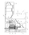
船体2内の船首側及び中央部には船倉10が設けられており、船体2内の船尾側には機関室11が設けられている。機関室11には、プロペラ5の駆動源と船舶1の電力供給源とを兼ねる推進兼発電機構12が船体中心線CLを挟んだ左右に振り分けて一対配置されている。各推進兼発電機構12から推進軸9に伝達された回転動力にて、各プロペラ5は回転駆動する。機関室11の内部は、上甲板13、第2甲板14、第3甲板15及び内底板16にて上下に仕切られている。第1実施形態の各推進兼発電機構12は、機関室11最下段の内底板16上に設置されている。なお、詳細は図示していないが、船倉10は複数の区画に分割されている。
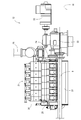
図2~図4に示すように、各推進兼発電機構12は、中速4ストロークのディーゼルエンジン21(以下、単にエンジンという)と、エンジン21の動力を推進軸9に伝達する減速機22と、エンジン21の動力にて発電する軸駆動発電機23とを組み合わせたものである。ここで、「中速」のエンジンとは、毎分500~1000回転程度の回転速度で駆動するものを意味している。ちなみに、「低速」のエンジンは毎分500回転以下の回転速度で駆動し、「高速」のエンジンは毎分1000回転以上の回転速度で駆動する。第1実施形態のエンジン21は中速の範囲内(毎分700~750回転程度)で定速駆動するように構成されている。
エンジン21は、エンジン出力軸24(クランク軸)を有するシリンダブロック25と、シリンダブロック25上に搭載されたシリンダヘッド26とを備えている。機関室11最下段の内底板16上に、直付け又は防振体(図示省略)を介してベース台27が据え付けられている。ベース台27上にエンジン21のシリンダブロック25が搭載されている。エンジン出力軸24は、船体2の前後長さ方向に沿う向きに延びている。すなわち、エンジン21は、エンジン出力軸24の向きを船体2の前後長さ方向に沿わせた状態で機関室11内に配置されている。
減速機22及び軸駆動発電機23はエンジン21よりも船首側に配置されている。エンジン21の前面側からエンジン出力軸24の前端側が突出している。当該前端側に減速機22が動力伝達可能に連結されている。減速機22を挟んでエンジン21と反対側に、軸駆動発電機23が配置されている。機関室11内の前方から軸駆動発電機23、減速機22、エンジン21の順に並べて配置されている。減速機22の動力伝達下流側に推進軸9が設けられている。
エンジン21の定速動力は、エンジン出力軸24の前端側から減速機22を介して、軸駆動発電機23と推進軸9とに分岐して伝達される。エンジン21の定速動力の一部は、減速機22によって例えば毎分100~120回転前後の回転速度に減速されて、推進軸9に伝達される。減速機22からの減速動力にてプロペラ5が回転駆動する。なお、第1実施形態のプロペラ5には、プロペラ羽根の翼角変更によって船速を調節可能な可変ピッチプロペラが採用されている。また、エンジン21の定速動力の一部は、減速機22によって例えば毎分1200か1800回転程度の回転速度に増速されて、減速機22に回転可能に軸支されたPTO軸42に伝達される。PTO軸42の前端側が軸駆動発電機23に動力伝達可能に連結されている。PTO軸42の回転動力が軸駆動発電機23を発電駆動させる。軸駆動発電機23の駆動にて生じた発電電力が船体2内の電気系統に供給される。
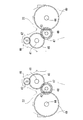
第1実施形態では、エンジン出力軸24の前端側が減速機22の減速機入力軸41(図5参照)に連結されている。減速機入力軸41は減速機22内に回転可能に軸支されている。減速機22内には、軸駆動発電機23に動力伝達するPTO軸42、推進軸9に動力伝達する減速機出力軸44及び中継軸43が減速機入力軸41と平行状に且つ回転可能に軸支されている。減速機入力軸41に固着された入力ギヤ45には、PTO軸42に固着されたPTOギヤ46と、中継軸43に固着された第1中継ギヤ47とに噛み合わせている。中継軸43には、第1中継ギヤ47以外に第2中継ギヤ48も固着されている。中継軸43の第2中継ギヤ48は、減速機出力軸44に固着された出力ギヤ49に噛み合わせている。
図3に示すように、減速機22の外形は、エンジン21及び軸駆動発電機23よりも左右外側に張り出している。当該張り出し部分の後面側に、推進軸9の前端側が動力伝達可能に連結されている。推進軸9の後部側は、船底7に一体形成されたスケグ8を貫通している。推進軸9の後端部にプロペラ5が取り付けられている。従って、推進軸9はエンジン21よりも左右外側に位置する。換言すると、平面視において、エンジン21を挟んで船体中心線CLと反対側に、推進軸9が位置することになる。
図2及び図4に示すように、エンジン出力軸24(軸芯線)と推進軸9とは、互いに平行状に延びている。推進軸9は、エンジン出力軸24(軸芯線)に対して鉛直方向に異芯した状態で、船体2の前後長さ方向に延びている。この場合、推進軸9は、側面視で推進軸9と対峙するシリンダブロック25側面にできるだけ被さらないように、エンジン出力軸24(軸芯線)よりも低く内底板16に近い位置に置かれている。
エンジン21には、空気取り込み用の吸気経路(図示省略)と排気ガス排出用の排気経路28とが接続されている。吸気経路を通じて取り込まれた空気は、エンジン21の各気筒内(吸気行程の気筒内)に送られる。各気筒の圧縮行程完了時に、燃料タンクから吸い上げられた燃料を燃料噴射装置にて気筒毎の燃焼室内に圧送することにより、各燃焼室にて混合気の自己着火燃焼に伴う膨張行程が行われる。
前述の通り、エンジン21は2基あるため、排気経路28は2本存在する。各排気経路28はそれぞれ延長経路29に接続されている。延長経路29はファンネル4まで延びていて、外部に直接連通するように構成されている。延長経路29の中途部には、主に排気ガスの浄化処理(NOx還元処理)をする排気ガス浄化装置としての後処理装置30が設けられている。各エンジン21からの排気ガスは、各排気経路28、延長経路29及び後処理装置30を経由して浄化処理をされた後、船舶1外に放出される。後処理装置30は機関室11の上部側に配置されている。第1実施形態では、機関室11中段の第3甲板15上に後処理装置30が据え付けられている。延長経路29のうち後処理装置30よりも上流側には、NOx還元用の還元剤である尿素水溶液(以下、尿素水という)を延長経路29内の排気ガスに供給する尿素水噴射ノズル31が設けられている。従って、第1実施形態では、1基の推進兼発電機構12(エンジン21といってもよい)に対して、1基の後処理装置30を備えている。なお、各排気経路28を1本の集合経路に合流させて、集合経路をファンネル4まで延出させ、集合経路の中途部に後処理装置30を設けてもよい。
後処理装置30は、略筒型に形成された耐熱金属材料製の後処理ケーシング32内に、上流側から順に、排気ガス中のNOxの還元を促進させるNOx触媒33と、余分に供給された還元剤(この場合は加水分解後のアンモニア)の酸化処理を促進させるスリップ処理触媒34と、排気ガスの排気音を減衰させる消音器35とを直列に並べて収容したものである。各触媒33,34は、多孔質な(ろ過可能な)隔壁にて区画された多数個のセルからなるハニカム構造になっていて、例えばアルミナ、ジルコニア、バナジア/チタニア又はゼオライト等の触媒金属を有している。
NOx触媒33は、尿素水噴射ノズル31からの尿素水の加水分解にて生じたアンモニアを還元剤として、排気ガス中のNOxを選択還元することにより、後処理装置30内に送られた排気ガスを浄化するものである。また、スリップ処理触媒34は、NOx触媒33から流出した未反応(余剰)のアンモニアを酸化して無害な窒素にするものである。この場合、後処理ケーシング32内では下記の反応式:
(NH2)2CO+H2O → 2NH3+CO2(加水分解)
NO+NO2+2NH3→ 2N2+3H2O(NOx触媒33での反応)
4NO+4NH3+O2→ 4N2+6H2O(NOx触媒33での反応)
6NO2+8NH3→ 7N2+12H2O(NOx触媒33での反応)
4NH3+3O2→ 2N2+6H2O(スリップ処理触媒34での反応)
が生ずることになる。
(NH2)2CO+H2O → 2NH3+CO2(加水分解)
NO+NO2+2NH3→ 2N2+3H2O(NOx触媒33での反応)
4NO+4NH3+O2→ 4N2+6H2O(NOx触媒33での反応)
6NO2+8NH3→ 7N2+12H2O(NOx触媒33での反応)
4NH3+3O2→ 2N2+6H2O(スリップ処理触媒34での反応)
が生ずることになる。
各エンジン21から排出された排気ガスは、後処理ケーシング32内に進入し、NOx触媒33及びスリップ処理触媒34を通過して浄化処理をされる。そして、浄化処理後の排出ガスは、消音器35を介して後処理ケーシング32外、ひいては船舶1外に放出される。
後処理ケーシング32内にNOx触媒33及びスリップ処理触媒34を収容することによって、NOx触媒33を未反応のまま通過しようとする余剰の還元剤(アンモニア)を、窒素に酸化処理して無害化でき、排気ガス中にアンモニアが残存するおそれを確実に回避できる。また、NOx触媒33とスリップ処理触媒34とをパッケージ化でき、排気構造の下流側をコンパクトに構成できる。後処理ケーシング32には消音器35を備えているから、NOx触媒33、スリップ処理触媒34及び消音器35を単一の後処理ケーシング32にパッケージ化でき、排気構造の下流側をコンパクトに構成できる。
以上の説明から明らかなように、第1実施形態では、ディーゼルエンジン21と、船舶推進用のプロペラ5を回転駆動させる推進軸9に前記ディーゼルエンジン21の動力を伝達する減速機22と、前記ディーゼルエンジン21の動力にて発電する軸駆動発電機23とを組み合わせた推進兼発電機構12を一対備えており、前記一対の推進兼発電機構12は、船体2内の機関室11に、船体中心線CLを挟んだ左右に振り分けて配置されるから、複数台のディーゼルエンジン(主機関及び補機関)を機関室内に配置する従来構造に比べて、前記機関室11のエンジン設置スペースを縮小できる。このため、前記機関室11の前後長を短縮して前記機関室11をコンパクトに構成でき、ひいては、前記船体2における船倉スペース(前記機関室11以外のスペース)の確保がし易い。2つの前記プロペラ5の駆動によって、船舶1の推進効率向上も図れる。前記各ディーゼルエンジン21によって前記プロペラ5の回転駆動と前記軸駆動発電機23の駆動とを行えるので、前記従来構造に比べて前記ディーゼルエンジン21の搭載数が2基のみと少なくて済む。従って、メンテナンスコスト及び部品交換コストの低減も図れる。
しかも、主機関たる前記ディーゼルエンジン21が2基備わるため、例えば1基の前記ディーゼルエンジン21が故障して駆動不能になったとしても、もう1基の前記ディーゼルエンジン21によって航行可能であり、船舶用原動機装置ひいては船舶1の冗長性を確保できる。その上、前述の通り、前記各ディーゼルエンジン21によって前記プロペラ5の回転駆動と前記軸駆動発電機23の駆動とを行えるから、通常航行時は、いずれか一方の前記軸駆動発電機23を予備にできる。従って、例えば1基の前記ディーゼルエンジン21又は前記軸駆動発電機23の故障によって電力供給が停止した場合、もう1基の前記軸駆動発電機23を起動させ、周波数及び電圧を確立して給電を復帰させればよい。また、1基の前記ディーゼルエンジン21だけでの航行時に前記ディーゼルエンジン21を停止させた場合は、もう1基の停止中の前記ディーゼルエンジン21、ひいてはこれに対応した前記軸駆動発電機23を起動させ、周波数及び電圧を確立して給電を復帰させればよい。すなわち、前記従来のような予備発電機を別個独立して備えなくても、船級規則を満足できると共に、製造コスト上も有利になる。
また、前記各推進兼発電機構12において、前記減速機22及び前記軸駆動発電機23は前記ディーゼルエンジン21よりも船首側に配置され、前記推進軸9は前記ディーゼルエンジン21よりも左右外側に配置されるから、前記船舶1における前記両推進兼発電機構12の設置バランスを確保した上で、前記両推進軸9間の左右配置間隔、ひいては前記両プロペラ5間の左右配置間隔を確実に確保できる。しかも、前記推進軸9は、前記ディーゼルエンジン21のエンジン出力軸24に対して鉛直方向に異芯した状態で配置されるから、前記ディーゼルエンジン21の側面に前記推進軸9が被さって塞ぐのを防止でき、前記ディーゼルエンジン21内部のメンテナンス作業性を向上できる。
更に、前記各推進兼発電機構12は、船首側から船尾側に向けて前記軸駆動発電機23、前記減速機22、前記ディーゼルエンジン21の順に並べて構成されているから、前記軸駆動発電機23と前記推進軸9とが前記減速機22を挟んで前後に振り分けられ、互いに干渉しない。従って、前記各推進兼発電機構12のコンパクトな配置が可能になる。
第1実施形態では、前記機関室11の上部側に、前記両ディーゼルエンジン21からの排気ガスを浄化処理する排気ガス浄化装置30を備えており、前記排気ガス浄化装置30を通過した排気ガスを前記船体2上部にあるファンネル4から排出するように構成されているから、エンジン設置スペースの縮小にて前記機関室11の上部に形成されるスペースを、前記排気ガス浄化装置30の設置箇所として有効に活用できる。前記機関室11を拡大することなく、前記排気ガス浄化装置30を簡単に設置できる。前記船体2底側に位置する前記ディーゼルエンジン21と前記船体2上部にあるファンネル4との間に、前記排気ガス浄化装置30を機能的に組み付けでき、前記ディーゼルエンジン21からの排気ガスの排気抵抗を増大させることなく、浄化性能を向上できる。
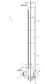
図6~図8は本願発明の第2実施形態を示している。ここで、第2実施形態において構成及び作用が第1実施形態と変わらないものは、第1実施形態の場合と同じ符号を付して、その詳細な説明を省略する。第2実施形態では、各推進兼発電機構12において、減速機22及び軸駆動発電機23がエンジン21よりも船尾側に配置されている。エンジン21の後面側からエンジン出力軸24の後端側が突出している。エンジン出力軸の後端側に減速機22が動力伝達可能に連結されている。減速機22を挟んでエンジン21と反対側に、軸駆動発電機23が配置されている。機関室11内の前方からエンジン21、減速機22、軸駆動発電機23の順に並べて配置されている。この場合、船尾側にあるスケグ8内又はその近傍に減速機22及び軸駆動発電機23が配置されている。従って、船舶1のバドックライン40の制約に拘らず、エンジン21をできるだけ船尾側に寄せて配置することが可能になっていて、機関室11のコンパクト化に寄与している。
減速機22の動力伝達下流側に推進軸9が設けられている。減速機22の外形は、エンジン21及び軸駆動発電機23よりも下側に張り出している。当該張り出し部分の後面側に、推進軸9の前端側が動力伝達可能に連結されている。エンジン出力軸24(軸芯線)と推進軸9とは、平面視で同軸状に位置している。推進軸9は、エンジン出力軸24(軸芯線)に対して鉛直方向に異芯した状態で、船体2の前後長さ方向に延びている。この場合、推進軸9は、側面視で軸駆動発電機23及びエンジン出力軸24(軸芯線)よりも低く内底板16に近い位置に置かれている。すなわち、軸駆動発電機23と推進軸9とが上下に振り分けられ、互いに干渉しない。従って、各推進兼発電機構12のコンパクト化が可能になる。その他の構成は第1実施形態と同様である。
以上の説明から明らかなように、第2実施形態では、前記各推進兼発電機構12において、前記減速機22及び前記軸駆動発電機23は、前記ディーゼルエンジン21よりも船尾側に配置され、前記推進軸9は、前記ディーゼルエンジン21の出力軸24と平面視で同軸状にあり、且つ、前記ディーゼルエンジン21の出力軸24に対して鉛直方向に異芯した状態で配置されるから、例えば船尾側にあるスケグ8内又はその近傍に前記減速機22及び前記軸駆動発電機23を配置して、前記船舶のバドックラインの制約に拘らず、前記ディーゼルエンジン21をできるだけ船尾側に配置することが可能になる。このため、前記機関室11のコンパクト化に効果的である。
また、前記各推進兼発電機構12は、船首側から船尾側に向けて前記ディーゼルエンジン21、前記減速機22、前記軸駆動発電機23の順に並べて構成されているから、前記軸駆動発電機23と前記推進軸9とが上下に振り分けられ、互いに干渉しない。従って、この場合も、前記各推進兼発電機構12のコンパクトな配置が可能になる。
その他、各部の構成は図示の実施形態に限定されるものではなく、本願発明の趣旨を逸脱しない範囲で種々変更が可能である。
1 船舶
2 船体
4 ファンネル
5 プロペラ
9 推進軸
11 機関室
12 推進兼発電機構
15 第3甲板
16 内底板
21 ディーゼルエンジン
22 減速機
23 軸駆動発電機
24 出力軸(クランク軸)
30 後処理装置
40 バドックライン
2 船体
4 ファンネル
5 プロペラ
9 推進軸
11 機関室
12 推進兼発電機構
15 第3甲板
16 内底板
21 ディーゼルエンジン
22 減速機
23 軸駆動発電機
24 出力軸(クランク軸)
30 後処理装置
40 バドックライン
Claims (7)
- ディーゼルエンジンと、船舶推進用のプロペラを回転駆動させる推進軸に前記ディーゼルエンジンの動力を伝達する減速機と、前記ディーゼルエンジンの動力にて発電する軸駆動発電機とを組み合わせた推進兼発電機構を一対備えており、
前記一対の推進兼発電機構は、船体内の機関室に、船体中心線を挟んだ左右に振り分けて配置される、
船舶用原動機装置。 - 前記各推進兼発電機構において、前記減速機及び前記軸駆動発電機は、前記ディーゼルエンジンよりも船首側に配置され、前記推進軸は、前記ディーゼルエンジンよりも左右外側に、且つ、前記ディーゼルエンジンの出力軸に対して鉛直方向に異芯した状態で配置される、
請求項1に記載した船舶用原動機装置。 - 前記各推進兼発電機構は、船首側から船尾側に向けて前記軸駆動発電機、前記減速機、前記ディーゼルエンジンの順に並べて構成されている、
請求項2に記載した船舶用原動機装置。 - 前記各推進兼発電機構において、前記減速機及び前記軸駆動発電機は、前記ディーゼルエンジンよりも船尾側に配置され、前記推進軸は、前記ディーゼルエンジンのエンジン出力軸と平面視で同軸状にあり、且つ、前記ディーゼルエンジンの出力軸に対して鉛直方向に異芯した状態で配置される、
請求項1に記載した船舶用原動機装置。 - 前記各推進兼発電機構は、船首側から船尾側に向けて前記ディーゼルエンジン、前記減速機、前記軸駆動発電機の順に並べて構成されている、
請求項4に記載した船舶用原動機装置。 - 前記機関室の上部側に、前記両ディーゼルエンジンからの排気ガスを浄化処理する排気ガス浄化装置を備えており、前記排気ガス浄化装置を通過した排気ガスを前記船体上部にあるファンネルから排出するように構成されている、
請求項1~5のうちいずれかに記載した船舶用原動機装置。 - 請求項1~6のうちいずれかに記載した船舶用原動機装置が搭載されている、
船舶。
Applications Claiming Priority (2)
| Application Number | Priority Date | Filing Date | Title |
|---|---|---|---|
| JP2012-241940 | 2012-11-01 | ||
| JP2012241940A JP6049060B2 (ja) | 2012-11-01 | 2012-11-01 | 船舶用原動機装置及びこれを備えた船舶 |
Publications (1)
| Publication Number | Publication Date |
|---|---|
| WO2014069417A1 true WO2014069417A1 (ja) | 2014-05-08 |
Family
ID=50627322
Family Applications (1)
| Application Number | Title | Priority Date | Filing Date |
|---|---|---|---|
| PCT/JP2013/079169 Ceased WO2014069417A1 (ja) | 2012-11-01 | 2013-10-28 | 船舶用原動機装置及びこれを備えた船舶 |
Country Status (2)
| Country | Link |
|---|---|
| JP (1) | JP6049060B2 (ja) |
| WO (1) | WO2014069417A1 (ja) |
Cited By (1)
| Publication number | Priority date | Publication date | Assignee | Title |
|---|---|---|---|---|
| WO2021190920A1 (de) * | 2020-03-23 | 2021-09-30 | Thyssenkrupp Marine Systems Gmbh | Wasserfahrzeug mit einem redundanten antriebssystem |
Families Citing this family (5)
| Publication number | Priority date | Publication date | Assignee | Title |
|---|---|---|---|---|
| KR101613220B1 (ko) * | 2014-08-01 | 2016-04-18 | 대우조선해양 주식회사 | 드릴쉽의 엔진 케이싱 배치구조 및 그 배치구조를 갖는 드릴쉽 |
| JP2016137766A (ja) * | 2015-01-26 | 2016-08-04 | 三井造船株式会社 | 船舶 |
| JP6617380B2 (ja) * | 2015-03-03 | 2019-12-11 | 三井E&S造船株式会社 | 船舶の機関室構造 |
| JP6457127B1 (ja) * | 2018-02-23 | 2019-01-23 | 株式会社新来島どっく | 船舶構造 |
| JP7288746B2 (ja) * | 2018-09-14 | 2023-06-08 | 三菱重工エンジン&ターボチャージャ株式会社 | 排ガス浄化装置、および排ガス浄化装置を備える船舶 |
Citations (2)
| Publication number | Priority date | Publication date | Assignee | Title |
|---|---|---|---|---|
| JP2004345628A (ja) * | 2004-03-26 | 2004-12-09 | Niigata Power Systems Co Ltd | 船舶の駆動制御方法 |
| JP2011057081A (ja) * | 2009-09-10 | 2011-03-24 | Mukaishima Dock Kk | 二層甲板貨物船及びその設計方法 |
Family Cites Families (2)
| Publication number | Priority date | Publication date | Assignee | Title |
|---|---|---|---|---|
| JP2801174B2 (ja) * | 1996-09-02 | 1998-09-21 | 日本操舵システム株式会社 | 電気推進装置と二枚舵装置とからなる船舶推進装置における船速切換方法 |
| JP2011235740A (ja) * | 2010-05-10 | 2011-11-24 | Kayseven Co Ltd | 船舶 |
-
2012
- 2012-11-01 JP JP2012241940A patent/JP6049060B2/ja active Active
-
2013
- 2013-10-28 WO PCT/JP2013/079169 patent/WO2014069417A1/ja not_active Ceased
Patent Citations (2)
| Publication number | Priority date | Publication date | Assignee | Title |
|---|---|---|---|---|
| JP2004345628A (ja) * | 2004-03-26 | 2004-12-09 | Niigata Power Systems Co Ltd | 船舶の駆動制御方法 |
| JP2011057081A (ja) * | 2009-09-10 | 2011-03-24 | Mukaishima Dock Kk | 二層甲板貨物船及びその設計方法 |
Cited By (1)
| Publication number | Priority date | Publication date | Assignee | Title |
|---|---|---|---|---|
| WO2021190920A1 (de) * | 2020-03-23 | 2021-09-30 | Thyssenkrupp Marine Systems Gmbh | Wasserfahrzeug mit einem redundanten antriebssystem |
Also Published As
| Publication number | Publication date |
|---|---|
| JP2014091368A (ja) | 2014-05-19 |
| JP6049060B2 (ja) | 2016-12-21 |
Similar Documents
| Publication | Publication Date | Title |
|---|---|---|
| JP6049060B2 (ja) | 船舶用原動機装置及びこれを備えた船舶 | |
| CN105683519B (zh) | 排出气体净化系统及具备它的船舶 | |
| JP6615076B2 (ja) | 船舶 | |
| CN102712355B (zh) | 船舶及船舶的运行方法 | |
| KR102097186B1 (ko) | 선박의 배기가스 정화 시스템 | |
| CN108350781A (zh) | 船舶的废气净化装置 | |
| CN105683522B (zh) | 发动机装置 | |
| CN108138622B (zh) | 船舶的废气净化装置 | |
| WO2010092855A1 (ja) | 排気ガス浄化システム | |
| JP6232257B2 (ja) | 排気ガス浄化システム及びこれを備えた船舶 | |
| JP5819753B2 (ja) | 電気推進船 | |
| CN105683523B (zh) | 发动机装置 | |
| JP6228427B2 (ja) | 船舶の排気ガス浄化システム | |
| JP5696199B2 (ja) | 船舶 | |
| CN201778871U (zh) | 船用选择性催化还原减排系统的反应器 | |
| WO2020054439A1 (ja) | 排ガス浄化装置、および排ガス浄化装置を備える船舶 | |
| JP2020020343A (ja) | 船舶 |
Legal Events
| Date | Code | Title | Description |
|---|---|---|---|
| 121 | Ep: the epo has been informed by wipo that ep was designated in this application |
Ref document number: 13850590 Country of ref document: EP Kind code of ref document: A1 |
|
| NENP | Non-entry into the national phase |
Ref country code: DE |
|
| 122 | Ep: pct application non-entry in european phase |
Ref document number: 13850590 Country of ref document: EP Kind code of ref document: A1 |