WO2014069119A1 - アルミニウム合金箔 - Google Patents
アルミニウム合金箔 Download PDFInfo
- Publication number
- WO2014069119A1 WO2014069119A1 PCT/JP2013/075077 JP2013075077W WO2014069119A1 WO 2014069119 A1 WO2014069119 A1 WO 2014069119A1 JP 2013075077 W JP2013075077 W JP 2013075077W WO 2014069119 A1 WO2014069119 A1 WO 2014069119A1
- Authority
- WO
- WIPO (PCT)
- Prior art keywords
- foil
- less
- aluminum alloy
- alloy foil
- strength
- Prior art date
- Legal status (The legal status is an assumption and is not a legal conclusion. Google has not performed a legal analysis and makes no representation as to the accuracy of the status listed.)
- Ceased
Links
Images

Classifications
-
- C—CHEMISTRY; METALLURGY
- C22—METALLURGY; FERROUS OR NON-FERROUS ALLOYS; TREATMENT OF ALLOYS OR NON-FERROUS METALS
- C22C—ALLOYS
- C22C21/00—Alloys based on aluminium
-
- C—CHEMISTRY; METALLURGY
- C22—METALLURGY; FERROUS OR NON-FERROUS ALLOYS; TREATMENT OF ALLOYS OR NON-FERROUS METALS
- C22C—ALLOYS
- C22C21/00—Alloys based on aluminium
- C22C21/02—Alloys based on aluminium with silicon as the next major constituent
-
- C—CHEMISTRY; METALLURGY
- C22—METALLURGY; FERROUS OR NON-FERROUS ALLOYS; TREATMENT OF ALLOYS OR NON-FERROUS METALS
- C22F—CHANGING THE PHYSICAL STRUCTURE OF NON-FERROUS METALS AND NON-FERROUS ALLOYS
- C22F1/00—Changing the physical structure of non-ferrous metals or alloys by heat treatment or by hot or cold working
- C22F1/04—Changing the physical structure of non-ferrous metals or alloys by heat treatment or by hot or cold working of aluminium or alloys based thereon
-
- C—CHEMISTRY; METALLURGY
- C22—METALLURGY; FERROUS OR NON-FERROUS ALLOYS; TREATMENT OF ALLOYS OR NON-FERROUS METALS
- C22F—CHANGING THE PHYSICAL STRUCTURE OF NON-FERROUS METALS AND NON-FERROUS ALLOYS
- C22F1/00—Changing the physical structure of non-ferrous metals or alloys by heat treatment or by hot or cold working
- C22F1/04—Changing the physical structure of non-ferrous metals or alloys by heat treatment or by hot or cold working of aluminium or alloys based thereon
- C22F1/043—Changing the physical structure of non-ferrous metals or alloys by heat treatment or by hot or cold working of aluminium or alloys based thereon of alloys with silicon as the next major constituent
-
- H—ELECTRICITY
- H01—ELECTRIC ELEMENTS
- H01M—PROCESSES OR MEANS, e.g. BATTERIES, FOR THE DIRECT CONVERSION OF CHEMICAL ENERGY INTO ELECTRICAL ENERGY
- H01M4/00—Electrodes
- H01M4/02—Electrodes composed of, or comprising, active material
- H01M4/64—Carriers or collectors
- H01M4/66—Selection of materials
- H01M4/661—Metal or alloys, e.g. alloy coatings
- H01M4/662—Alloys
-
- Y—GENERAL TAGGING OF NEW TECHNOLOGICAL DEVELOPMENTS; GENERAL TAGGING OF CROSS-SECTIONAL TECHNOLOGIES SPANNING OVER SEVERAL SECTIONS OF THE IPC; TECHNICAL SUBJECTS COVERED BY FORMER USPC CROSS-REFERENCE ART COLLECTIONS [XRACs] AND DIGESTS
- Y02—TECHNOLOGIES OR APPLICATIONS FOR MITIGATION OR ADAPTATION AGAINST CLIMATE CHANGE
- Y02E—REDUCTION OF GREENHOUSE GAS [GHG] EMISSIONS, RELATED TO ENERGY GENERATION, TRANSMISSION OR DISTRIBUTION
- Y02E60/00—Enabling technologies; Technologies with a potential or indirect contribution to GHG emissions mitigation
- Y02E60/10—Energy storage using batteries
Definitions
- the present invention relates to an aluminum alloy foil.
- aluminum alloy foil has been used in various fields.
- aluminum alloy foil has been used as a secondary battery such as a lithium ion battery or a current collector of an electric double layer capacitor from the viewpoint of being thin and conductive.
- a layer containing a positive electrode active material and a binder is applied to one surface of an aluminum alloy foil as a current collector and dried. Then, the positive electrode is manufactured by rolling in order to improve the density of the positive electrode active material and the adhesion to the foil.
- the aluminum alloy foil for example, in Patent Document 3, Si: 0.01 to 0.60 mass%, Fe: 0.2 to 1.0 mass%, Cu: 0.05 to 0.50 mass% , Mn: Aluminum alloy for lithium ion batteries containing 0.5 to 1.5 mass%, the balance being Al and inevitable impurities, tensile strength is 240 MPa or more, and n value is 0.1 or more A foil is disclosed.
- Patent Document 4 although not an aluminum alloy foil for a lithium ion battery, Si: 0.05 to 0.30 mass%, Fe: 0.15 to 0.60 mass%, Cu: 0.01 to Disclosed is an aluminum alloy foil for porous processing containing 0.20% by mass, the balance being Al and inevitable impurities, a tensile strength of about 186 to 212 N / mm 2 and a foil thickness of about 30 ⁇ m to 100 ⁇ m. Yes.
- JP 2007-234277 A Japanese Patent Laid-Open No. 11-67220 JP 2011-26656 A JP 2006-283114 A
- the conventional aluminum alloy foil has the following problems. That is, as described above, the aluminum alloy foil receives a compressive force by rolling or the like when manufacturing a foil-use member such as a battery electrode. Therefore, the aluminum alloy foil is required to have sufficient strength so as not to cause unnecessary deformation and breakage against such a compressive force. In recent years, further thinning of the foil has been demanded, and in order to cope with this, further improvement in strength is desired.
- the present invention has been made in view of such a background, and has been obtained in an attempt to provide an aluminum alloy foil capable of further improving the strength without greatly impairing conductivity.
- the chemical component includes, by mass, Si: 0.1% to 0.6%, Fe: 0.2% to 1.0%, and the balance is Al and inevitable Subgrains with a crystal grain size of 2 ⁇ m or less, when a boundary consisting of impurities and having a foil thickness of 20 ⁇ m or less and an orientation difference between adjacent crystal orientation measurement points of 5 ° ⁇ 0.2 ° is defined as a grain boundary
- the aluminum alloy foil is characterized by having an area ratio of 40% or more, a tensile strength of 210 MPa or more, and a specific resistance measured in liquid nitrogen of 0.45 ⁇ ⁇ cm to 0.7 ⁇ ⁇ cm. It is in.
- the aluminum alloy foil has the specific configuration described above, it is possible to further improve the strength without greatly impairing the conductivity. Since the aluminum alloy foil can exhibit sufficient strength by further improving the strength, for example, unnecessary plasticity even when a compressive force is applied by rolling or the like when manufacturing a foil-use member such as a battery electrode. Deformation can be suppressed, and thinning of the foil can be easily realized. Moreover, the said aluminum alloy foil can ensure favorable electroconductivity, without impairing electroconductivity largely by strength improvement. Therefore, if the said aluminum alloy foil is used as an electrical power collector of an electrode in secondary batteries, such as a lithium ion battery, for example, it can contribute to the high density and high energy of a battery.
- secondary batteries such as a lithium ion battery
- Si 0.1% to 0.6% Si is an element necessary for improving the foil strength.
- the temperature of the aluminum alloy exceeds 350 ° C. during the production of the foil, the dissolved Si and Fe precipitate as Al—Fe—Si compounds, which reduces the work hardening during cold rolling and reduces the foil strength. Is prone to decline. For this reason, it is desirable to perform hot rolling under conditions of 350 ° C. or lower without performing homogenization at a high temperature during foil production. However, it is possible to increase the foil strength and reduce the specific resistance of the foil under these conditions. In order to ensure this, the Si content needs to be 0.1% or more and 0.6% or less. When the Si content is less than 0.1%, the specific resistance of the foil is reduced, but the strength of the foil is not improved.
- the Si content exceeds 0.6%, it is difficult to further improve the foil strength, and coarse Si single-phase particles are formed. If the foil thickness is 20 ⁇ m or less, the problem of pinholes and foil breakage tends to occur.
- the Si content is preferably 0.12% or more.
- the Si content is preferably 0.4% or less.
- Fe 0.2% or more and 1.0% or less Fe is an element necessary for improving the foil strength after Si.
- the temperature of the aluminum alloy exceeds 350 ° C during foil production, the dissolved Si and Fe precipitate as Al-Fe-Si compounds, reducing the work hardenability during cold rolling and reducing the foil strength. It's easy to do. For this reason, it is desirable to perform hot rolling under conditions of 350 ° C. or lower without performing homogenization at a high temperature exceeding 350 ° C. during foil production, but under these conditions, the foil strength is increased and the specific resistance of the foil is reduced. In order to ensure conductivity, the Fe content needs to be 0.2% or more and 1.0% or less.
- the Fe content is less than 0.2%, the specific resistance of the foil is reduced, but the strength of the foil is not improved.
- the Fe content exceeds 1.0% it is difficult to further improve the foil strength, and a coarse Al—Fe crystallized product is formed during casting.
- the Al—Fe crystallized product formed during casting remains in a coarse state up to the final foil thickness. Will do. Therefore, the problem of pinholes and foil breakage tends to occur at a foil thickness of 20 ⁇ m or less.
- addition of Fe more than necessary also causes an increase in manufacturing cost.
- the Fe content is preferably 0.30% or more.
- the Fe content is preferably 0.80% or less.
- the above chemical component may further contain Cu: 0.01% or more and 0.25% or less by mass%.
- Cu 0.01% or more and 0.25% or less by mass%.
- Cu 0.01% or more and 0.25% or less
- Cu is an element that contributes to improving the strength of the foil.
- the Cu content is preferably 0.01% or more. Note that Cu of less than 0.01% may be included as an inevitable impurity.
- the Cu content is preferably 0.25% or less.
- the Cu content is preferably 0.02% or more.
- the Cu content is preferably 0.18% or less.
- the chemical component can contain elements such as Mn, Mg, Cr, Zn, Ni, Ga, V, and Ti as inevitable impurities.
- Mn and Mg are excessively contained, the specific resistance of the foil is increased and the electrical conductivity may be deteriorated. Therefore, it is preferable that the Mn content is 0.01% or less and the Mg content is 0.01% or less. Since other elements such as Cr, Zn, Ni, Ga, V, and Ti are elements that do not contribute to the increase in specific resistance, the content of each element is preferably 0.05% or less. Further, if the total content of inevitable impurities as a whole is 0.15% or less, it can be tolerated because it does not substantially affect the foil strength and conductivity.
- the foil thickness is 20 ⁇ m or less. If the foil thickness exceeds 20 ⁇ m, it cannot cope with the thinning of the foil (foil thickness gauge down), which is often required in recent years. Since the aluminum alloy foil has a foil thickness of 20 ⁇ m or less, the aluminum alloy foil is particularly suitable for use as a current collector for battery electrodes, for example, where there is a great demand for thin foil.
- the thickness of the foil is preferably less than 20 ⁇ m, more preferably 19 ⁇ m or less, still more preferably 18 ⁇ m or less, and even more preferably 17 ⁇ m or less, from the viewpoint of reducing the thickness and contributing to downsizing of batteries and the like. It can be.
- the thickness of the foil is preferably 8 ⁇ m or more, more preferably 9 ⁇ m or more, and even more preferably 10 ⁇ m or more, for example, from the viewpoint of ease of handling at the time of manufacturing a foil-use member such as a battery.
- the area ratio of subgrains having a crystal grain size of 2 ⁇ m or less is 40%. That's it. Specifically, the area ratio of the subgrain is determined by using a scanning electron microscope / Electron Back Scatter Diffraction (SEM / EBSD method) step size (distance between crystal orientation measurement points). The area of the foil surface of 900 ⁇ m 2 is analyzed at 0.1 ⁇ m, and the boundary where the orientation difference between adjacent crystal orientation measurement points is 5 ° ⁇ 0.2 ° is regarded as a crystal grain boundary and occupies the area of the measurement area. It is obtained by calculating the ratio (%) of the area of subgrains having a crystal grain size of 2 ⁇ m or less.
- the area ratio of the subgrain is less than 40%, the tensile strength of the foil is lowered and the strength of the foil is lowered.
- the area ratio of the subgrains is preferably 45% or more, more preferably 50% or more, and further preferably 55% or more, from the viewpoint of further improving the strength.
- the area ratio of the subgrain is preferably as high as possible, and ideally 100%, but the upper limit can be 80% or less from the viewpoint of actual manufacturing.
- the tensile strength of the aluminum alloy foil is 210 MPa or more. If the tensile strength is less than 210 MPa, it cannot be said that the strength is further improved. Further, if the tensile strength is less than 210 MPa, unnecessary plastic deformation is likely to occur when a compressive force by rolling or the like is applied to the foil during thinning.
- the tensile strength is preferably 213 MPa or more, more preferably 215 MPa or more, and further preferably 220 MPa or more.
- the upper limit of the tensile strength is not particularly limited, but can be determined within an optimum range in consideration of the balance with the specific resistance.
- the tensile strength can be, for example, about 330 MPa or less.
- the tensile strength is a value measured according to JIS Z2241.
- the specific resistance is 0.45 ⁇ ⁇ cm or more and 0.7 ⁇ ⁇ cm or less.
- the specific resistance is a value measured in liquid nitrogen.
- the specific resistance is measured in liquid nitrogen in order to remove the influence of the measurement ambient temperature.
- the specific resistance correlates with the solid solution amount of the alloy components Si and Fe.
- the specific resistance is within the above range, it is easy to further improve the strength without greatly impairing the conductivity.
- the specific resistance is less than 0.45 ⁇ ⁇ cm, it is difficult to improve the strength by work hardening at the time of manufacturing the foil, and it becomes difficult to set the tensile strength to 210 MPa or more.
- the specific resistance is preferably 0.50 ⁇ ⁇ cm or more, more preferably 0.55 ⁇ ⁇ cm or more.
- the specific resistance is increased, the strength is improved by work hardening at the time of manufacturing the foil, but the specific resistance increases and the conductivity tends to decrease.
- the specific resistance is preferably about 0.7 ⁇ ⁇ cm, which is about 60% of the specific resistance of the 3003 series aluminum alloy foil, which is a relatively high strength aluminum alloy foil.
- the specific resistance is preferably 0.69 ⁇ ⁇ cm or less, more preferably 0.68 ⁇ ⁇ cm or less.
- the specific resistance can be measured by a double bridge method in accordance with JIS H0505.
- the aluminum alloy foil can be used as a current collector for battery electrodes.
- an electrode active material is attached to the surface of the aluminum alloy foil as a current collector.
- a layer containing an electrode active material is applied to the surface of the aluminum alloy foil, and a compressive force by rolling or the like is applied after drying.
- the aluminum alloy foil is unlikely to undergo unnecessary plastic deformation due to the compressive force, so that the electrode active material is difficult to peel off, and good electrical conductivity can be secured.
- the said aluminum alloy foil has foil strength, it is easy to respond to the request
- the aluminum alloy foil can be manufactured, for example, as follows. That is, the aluminum alloy foil can be obtained by hot rolling an aluminum alloy ingot composed of the specific chemical component and then performing cold rolling including foil rolling.
- the aluminum alloy ingot is preferably hot-rolled without being homogenized at a high temperature.
- Hot rolling starts after heating to a temperature of 350 ° C. or lower, and the temperature at the start of hot rolling, during hot rolling, and at the end of hot rolling can be 350 ° C. or lower.
- the holding time after reaching the hot rolling start temperature is not particularly limited, but may be within 12 hours from the viewpoint of easily suppressing the precipitation of the Al—Fe—Si compound. it can.
- the hot rolling may be performed once, or may be performed in a plurality of times, such as finish rolling after rough rolling.
- the foil thickness is set to 20 ⁇ m or less without annealing in the middle. This is because annealing during the process promotes precipitation of the Al—Fe—Si compound, lowers work hardenability during cold rolling, and causes a decrease in foil strength.
- the final rolling rate in the cold rolling is preferably 90% or more, and more preferably 95% or more, from the viewpoint of improving the foil strength.
- Final rolling rate is 100 ⁇ (thickness of hot rolled sheet before cold rolling ⁇ thickness of aluminum alloy foil after final cold rolling) / (thickness of hot rolled sheet before cold rolling) It is a value calculated from Moreover, in foil rolling with a thickness of 200 ⁇ m or less, the temperature of the foil before foil rolling, the rolling reduction, the rolling speed, cooling with rolling oil, etc. are adjusted, and the temperature during foil rolling is preferably 120 ° C. or less. This is because the area ratio of the subgrains having the crystal grain size of 2 ⁇ m or less is likely to be 40% or more.
- the aluminum alloy foil according to the example will be described below.
- Example 1 An aluminum alloy ingot was prepared by ingot forming and chamfering an aluminum alloy having chemical components shown in Table 1 by a semi-continuous casting method.
- alloys A to K are aluminum alloys having chemical components suitable for the examples
- alloys L to Q are aluminum alloys having chemical components as comparative examples.
- the above-prepared aluminum alloy ingot was hot-rolled without subjecting it to a homogenization treatment to obtain a hot-rolled plate having a thickness of 2 mm.
- hot rolling rough rolling and finish rolling were continuously performed.
- the aluminum alloy ingot before being subjected to the rough rolling is heated to 350 ° C. and held for 6 hours to set the rough rolling start temperature (hot rolling start temperature) to 350 ° C. .
- the end temperature of rough rolling temperature during hot rolling
- the end temperature of the foil rolling was all adjusted to 120 ° C. or less.
- the final rolling rate in the cold rolling is 100 ⁇ (the thickness of the hot rolled sheet before cold rolling is 2000 ⁇ m ⁇ the thickness of the aluminum alloy foil after the final cold rolling is 12 ⁇ m) / (before the cold rolling)
- tensile strength, yield strength and elongation, specific resistance (electrical resistivity), and area ratio of subgrains having a crystal grain size of 2 ⁇ m or less were measured.
- the tensile strength, proof stress and elongation were measured in accordance with JIS Z2241, by collecting a JIS No. 5 test piece from the test material.
- the specific resistance was measured by a double bridge method according to JIS H0505. In order to remove the influence of the ambient temperature, the specific resistance was measured in liquid nitrogen.
- the area ratio of subgrains with a grain size of 2 ⁇ m or less is determined by the SEM / EBSD method after finishing the sample surface by electropolishing (electropolishing for 10 V-90 seconds in ethanol perchlorate cooled to ⁇ 5 ° C.). Using this, the area of the sample surface of 900 ⁇ m 2 is analyzed at a step size of 0.1 ⁇ m, and the boundary where the orientation difference between adjacent crystal orientation measurement points is 5 ° ⁇ 0.2 ° is regarded as the crystal grain boundary, and the above measurement is performed. It calculated
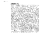
- FIG. 1 shows the results of measuring the area ratio of subgrains having a crystal grain size of 2 ⁇ m or less by the SEM / EBSD method for the test material E11.
- FIG. 2 shows the results of measuring the area ratio of subgrains having a crystal grain size of 2 ⁇ m or less by the SEM / EBSD method for the test material C1. In both figures, subgrains having a crystal grain size of 2 ⁇ m or less are shown in gray.
- the test materials E1 to E11 are examples, and the test materials C1 to C4 are comparative examples.
- the test material C1 uses an alloy L having an Si content of less than 0.1% and an Fe content of less than 0.2%, and has a sub-grain size of 2 ⁇ m or less. Grain area ratio is as low as 25%. Therefore, the test material C1 did not have the effect of further improving the strength, and the tensile strength was as low as less than 210 MPa.
- test material C2 used the alloy M having an Si content exceeding 0.6%, coarse Si single-phase particles were formed, and pinholes were generated due to this.
- the test material C3 uses an alloy N having an Fe content of less than 0.2%, and the area ratio of subgrains having a crystal grain size of 2 ⁇ m or less is as low as less than 40%. Therefore, the test material C3 did not have the effect of further improving the strength, and the tensile strength was as low as less than 210 MPa.
- test material C4 used the alloy O having an Fe content exceeding 1.0%, coarse Al—Fe-based particles were formed, and pinholes were generated due to this.
- test materials E1 to E11 are all made of the alloys A to K having the specific chemical components described above, and the area ratio of subgrains having a foil thickness of 20 ⁇ m or less and a crystal grain size of 2 ⁇ m or less is 40% or more.
- the tensile strength is 210 MPa or more.
- the test materials E1 to E11 all have a specific resistance measured in liquid nitrogen of 0.45 ⁇ ⁇ cm or more and 0.7 ⁇ ⁇ cm or less, indicating that the conductivity is not significantly reduced.
- an aluminum alloy foil capable of further improving the strength without greatly impairing the conductivity.
- the reason why such an aluminum alloy foil was obtained was that the cold rolling of 95% or more was performed, and when the foil thickness was 20 ⁇ m or less, the recovery of the structure was delayed, and the effect of exhibiting a fine subgrain structure was obtained. It is thought that it was big.
- the aluminum alloy foil has high strength even if it is thinned, and problems such as pinholes and foil breakage can also be avoided.
- Example 2 An aluminum alloy ingot was prepared by ingot forming and chamfering aluminum alloy B having chemical components shown in Table 1 by a semi-continuous casting method. In addition, a comparative aluminum alloy ingot was also prepared by ingoting and chamfering 1050 alloy (alloy P) and 3003 alloy (alloy Q) of conventional alloys shown in Table 1 by a semi-continuous casting method. .
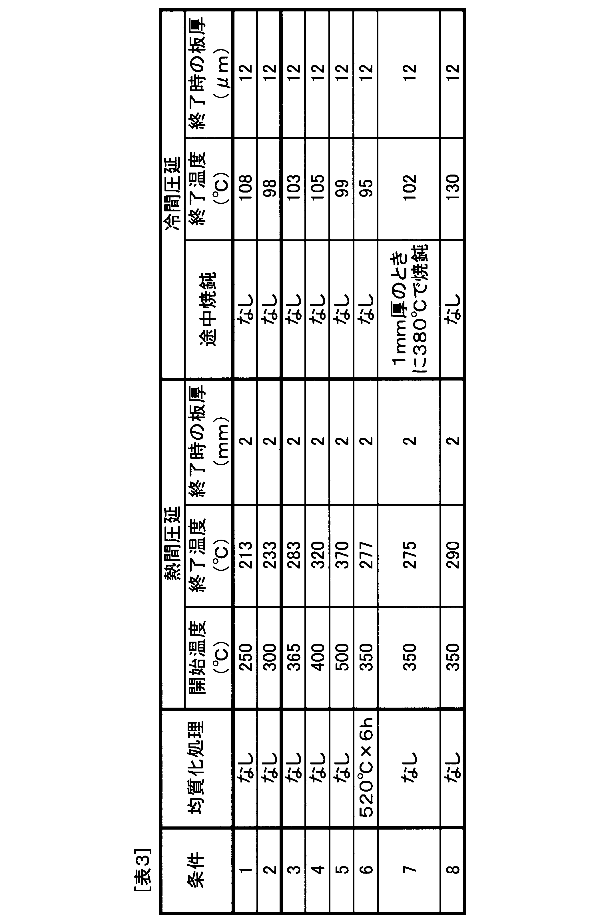
- an aluminum alloy foil having a foil thickness of 12 ⁇ m was produced under the production conditions shown in Table 3.
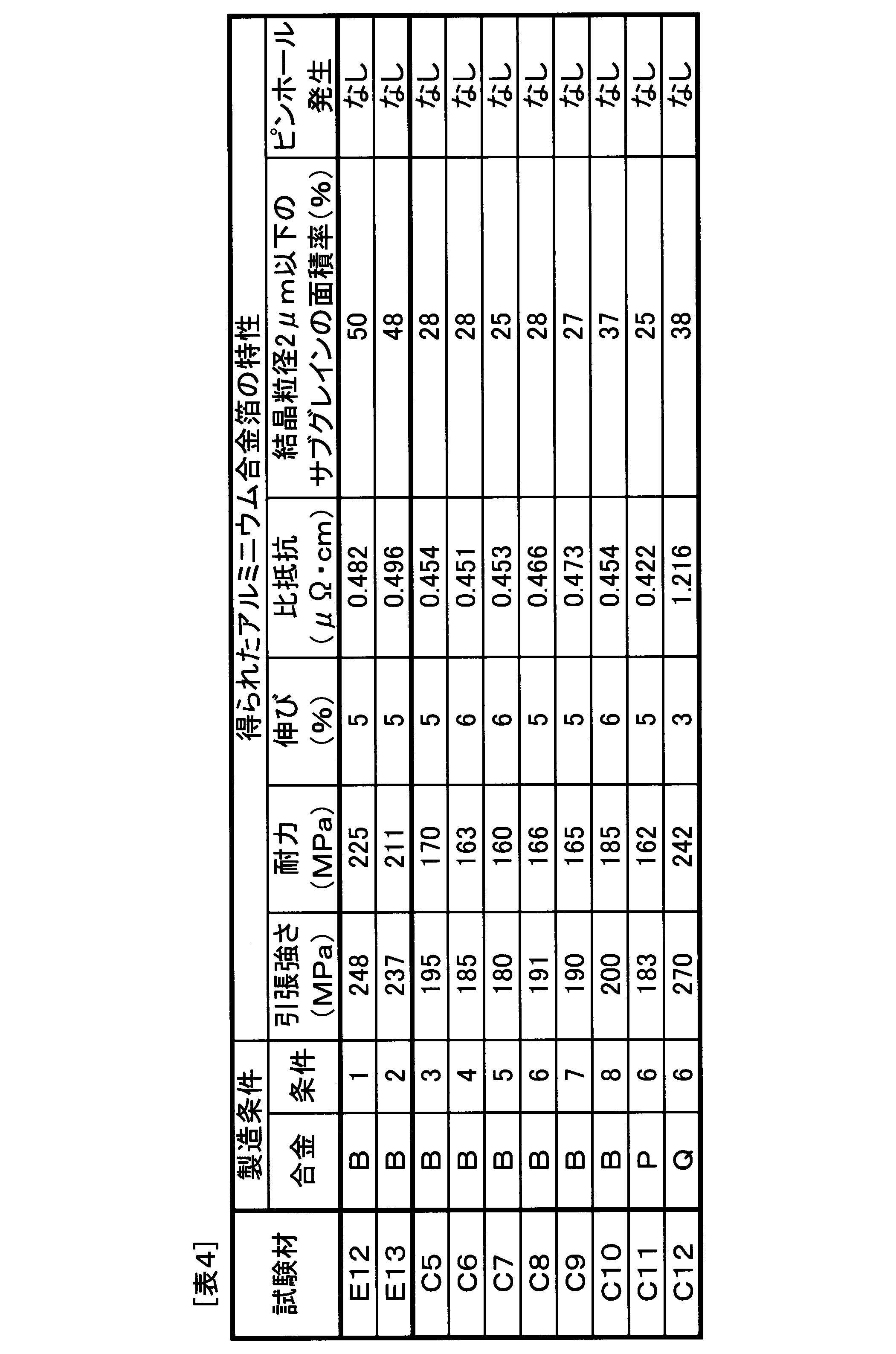
- the obtained aluminum alloy foil, the tensile strength, the proof stress and the elongation, the specific resistance (electrical resistivity), and the area ratio of subgrains having a crystal grain size of 2 ⁇ m or less were measured in the same manner as in Example 1, and the foil rolling situation (Existence of occurrence of pin pole) was investigated.
- the results are shown in Table 4.
- the test materials E12 and E13 are examples, and the test materials C5 to C12 are comparative examples.
- the hot rolling start temperature at the time of hot rolling exceeded 350 ° C., so that the area ratio of subgrains having a crystal grain size of 2 ⁇ m or less was less than 40%, The tensile strength was as low as less than 210 MPa.
- Test material C8 was produced by performing a homogenization treatment at 520 ° C. before the start of hot rolling. Therefore, in the test material C8, an Al—Fe—Si-based compound is formed, the amount of solid solution of Si and Fe is reduced, the area ratio of subgrains having a crystal grain size of 2 ⁇ m or less is less than 40%, and the tensile strength is low. It was as low as less than 210 MPa.
- the test material C9 is manufactured by performing an intermediate annealing at 380 ° C. when the plate thickness is 1 mm during the cold rolling. Therefore, in the test material C9, precipitation of the Al—Fe—Si based compound was promoted, the area ratio of subgrains having a crystal grain size of 2 ⁇ m or less was less than 40%, and the tensile strength was lowered to less than 210 MPa.
- Test material C10 had an end temperature of cold rolling of 130 ° C. at the time of production. Therefore, the test material C10 had a subgrain area ratio of less than 40% and a tensile strength of less than 210 MPa.
- test materials C11 and C12 1050 alloy (alloy P) and 3003 alloy (alloy Q), which are conventional alloys, are used, and further homogenized at a high temperature of 500 ° C. exceeding 350 ° C. before the start of hot rolling. Have been made. Therefore, the test material C11 has the same chemical composition as that of the conventional alloy 1050 alloy (alloy P). Less than 40%. Since the test material C12 has the same chemical composition as the conventional alloy 3003 alloy (alloy Q), the specific resistance is as extremely high as 1.2 ⁇ ⁇ cm or more, and the conductivity is inferior.
- test materials E12 and E13 are both made of the alloy B having the specific chemical component described above, and the area ratio of the subgrains having a foil thickness of 20 ⁇ m or less and a crystal grain size of 2 ⁇ m or less is 40% or more.
- the strength is 210 MPa or more.
- the specific resistance measured in liquid nitrogen is 0.45 microhm * cm or more and 0.7 microohm * cm or less, and it turns out that electroconductivity does not fall large.
Landscapes
- Chemical & Material Sciences (AREA)
- Engineering & Computer Science (AREA)
- Materials Engineering (AREA)
- Mechanical Engineering (AREA)
- Metallurgy (AREA)
- Organic Chemistry (AREA)
- Physics & Mathematics (AREA)
- Thermal Sciences (AREA)
- Crystallography & Structural Chemistry (AREA)
- Electrochemistry (AREA)
- General Chemical & Material Sciences (AREA)
- Chemical Kinetics & Catalysis (AREA)
- Cell Electrode Carriers And Collectors (AREA)
Abstract
Description
Siは、箔強度の向上を図るために必要な元素である。箔製造時にアルミニウム合金の温度が350℃を超えると、固溶していたSiおよびFeがAl-Fe-Si系化合物として析出し、これにより冷間圧延時の加工硬化性が低減して箔強度が低下しやすい。そのため、箔製造時に高温での均質化処理を行わず、350℃以下の条件で熱間圧延を行うことが望ましいが、この条件下で箔強度を高め、箔の比抵抗を低減して導電性を確保するためには、Si含有量を0.1%以上0.6%以下とする必要がある。Si含有量が0.1%未満になると、箔の比抵抗は低減するが、箔の強度が向上しない。Si含有量が0.6%を超えると、さらなる箔強度の向上が困難となり、粗大なSi単相粒子が形成されて20μm以下の箔厚ではピンホールや箔切れの問題が生じやすくなる。Si含有量は、好ましくは0.12%以上であるとよい。Si含有量は、好ましくは0.4%以下であるとよい。
Feは、Siに次いで箔強度の向上を図るために必要な元素である。箔製造時にアルミニウム合金の温度が350℃を超えると、固溶していたSiおよびFeがAl-Fe-Si系化合物として析出し、冷間圧延時の加工硬化性が低減して箔強度が低下しやすい。そのため、箔製造時に350℃を超える高温で均質化処理を行わず、350℃以下の条件で熱間圧延を行うことが望ましいが、この条件下で箔強度を高め、箔の比抵抗を低減して導電性を確保するためには、Fe含有量を0.2%以上1.0%以下とする必要がある。Fe含有量が0.2%未満になると、箔の比抵抗は低減するが、箔の強度が向上しない。Fe含有量が1.0%を超えると、さらなる箔強度の向上が困難となり、粗大なAl-Fe系晶出物が鋳造時に形成される。上記の通り、アルミニウム合金鋳塊に対して350℃を超える高温で均質化処理を行わない場合には、鋳造時に形成されたAl-Fe系晶出物は粗大な状態のまま最終箔厚まで残存することになる。そのため、20μm以下の箔厚ではピンホールや箔切れの問題が生じやすくなる。また、必要以上のFe添加は、製造コスト増加の原因にもなる。Fe含有量は、好ましくは0.30%以上であるとよい。Fe含有量は、好ましくは0.80%以下であるとよい。
Cuは、箔の強度向上に寄与する元素である。その効果を得るため、Cu含有量は0.01%以上とすることが好ましい。なお、0.01%未満のCuは、不可避的不純物として含まれていてもよい。一方、Cu含有量が過大になると箔の強度が増加するが比抵抗も増加する。そのため、Cu含有量は0.25%以下とすることが好ましい。Cu含有量は、好ましくは0.02%以上であるとよい。Cu含有量は、好ましくは0.18%以下であるとよい。
表1に示す化学成分のアルミニウム合金を半連続鋳造法にて造塊し面削することにより、アルミニウム合金鋳塊を準備した。なお、表1に示す化学成分のアルミニウム合金のうち、合金A~Kが実施例に適する化学成分のアルミニウム合金であり、合金L~Qが比較例としての化学成分のアルミニウム合金である。

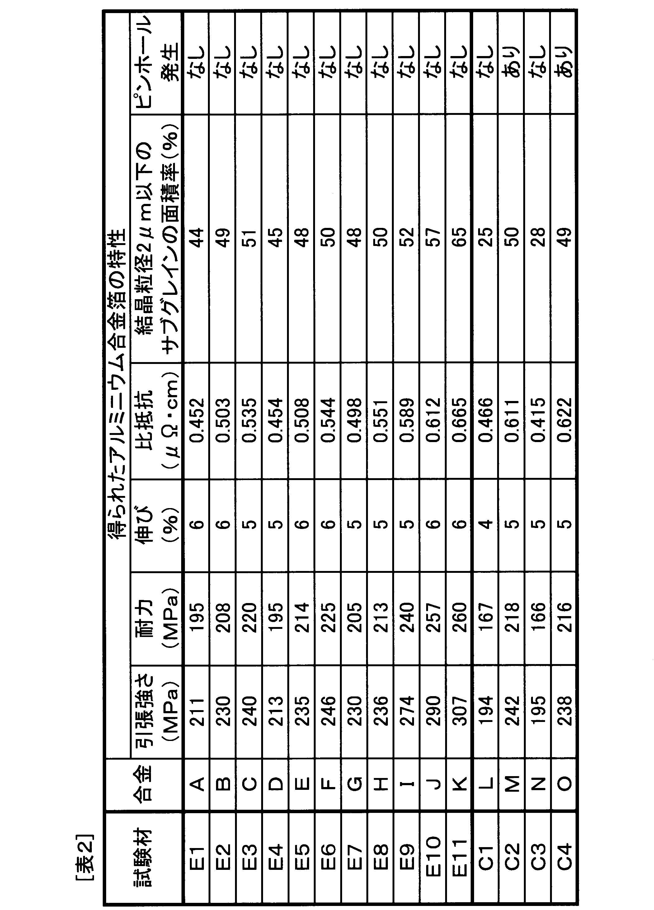
表1に示す化学成分のアルミニウム合金Bを半連続鋳造法にて造塊し面削することにより、アルミニウム合金鋳塊を準備した。また、表1に示す従来合金の1050合金(合金P)、3003合金(合金Q)を半連続鋳造法にて造塊し面削することにより、比較としてのアルミニウム合金鋳塊もあわせて準備した。
Claims (3)
- 化学成分が、質量%で、Si:0.1%以上0.6%以下、Fe:0.2%以上1.0%以下を含有し、残部がAlおよび不可避的不純物からなり、
箔厚が20μm以下であり、
隣接する結晶方位測定点間の方位差が5°±0.2°である境界を結晶粒界と規定した場合、結晶粒径2μm以下のサブグレインの面積率が40%以上であり、
引張強さが210MPa以上であり、
液体窒素中で測定した比抵抗が0.45μΩ・cm以上0.7μΩ・cm以下であることを特徴とするアルミニウム合金箔。 - 上記化学成分が、質量%で、Cu:0.01%以上0.25%以下をさらに含有することを特徴とする請求項1に記載のアルミニウム合金箔。
- 上記アルミニウム合金箔は、電池電極の集電体用であることを特徴とする請求項1または2に記載のアルミニウム合金箔。
Priority Applications (4)
| Application Number | Priority Date | Filing Date | Title |
|---|---|---|---|
| KR1020157011234A KR20150070201A (ko) | 2012-10-30 | 2013-09-18 | 알루미늄 합금박 |
| CN201380056002.6A CN104769141B (zh) | 2012-10-30 | 2013-09-18 | 铝合金箔 |
| MYPI2015701320A MY182959A (en) | 2012-10-30 | 2013-09-18 | Aluminum alloy foil |
| DE112013005208.3T DE112013005208T5 (de) | 2012-10-30 | 2013-09-18 | Aluminiumlegierungsfolie |
Applications Claiming Priority (2)
| Application Number | Priority Date | Filing Date | Title |
|---|---|---|---|
| JP2012-239312 | 2012-10-30 | ||
| JP2012239312A JP5959405B2 (ja) | 2012-10-30 | 2012-10-30 | アルミニウム合金箔 |
Publications (1)
| Publication Number | Publication Date |
|---|---|
| WO2014069119A1 true WO2014069119A1 (ja) | 2014-05-08 |
Family
ID=50627035
Family Applications (1)
| Application Number | Title | Priority Date | Filing Date |
|---|---|---|---|
| PCT/JP2013/075077 Ceased WO2014069119A1 (ja) | 2012-10-30 | 2013-09-18 | アルミニウム合金箔 |
Country Status (6)
| Country | Link |
|---|---|
| JP (1) | JP5959405B2 (ja) |
| KR (1) | KR20150070201A (ja) |
| CN (1) | CN104769141B (ja) |
| DE (1) | DE112013005208T5 (ja) |
| MY (1) | MY182959A (ja) |
| WO (1) | WO2014069119A1 (ja) |
Cited By (1)
| Publication number | Priority date | Publication date | Assignee | Title |
|---|---|---|---|---|
| CN117587285A (zh) * | 2023-12-06 | 2024-02-23 | 浙江永杰铝业有限公司 | 高延展性电池铝箔及其制备方法 |
Families Citing this family (10)
| Publication number | Priority date | Publication date | Assignee | Title |
|---|---|---|---|---|
| CN104388766B (zh) * | 2014-11-27 | 2017-01-11 | 广西南南铝箔有限责任公司 | 一种锂离子电池用铝箔的生产方法 |
| JP6631051B2 (ja) * | 2015-06-30 | 2020-01-15 | 住友電気工業株式会社 | リード導体、及び電力貯蔵デバイス |
| US11255001B2 (en) | 2016-03-11 | 2022-02-22 | Uacj Corporation | Aluminum-alloy foil |
| JP6769727B2 (ja) * | 2016-04-07 | 2020-10-14 | 三菱アルミニウム株式会社 | 電池集電体用アルミニウム合金箔およびその製造方法 |
| CN114843666B (zh) | 2016-12-28 | 2024-08-13 | 大日本印刷株式会社 | 电池用包装材料用铝合金箔、电池用包装材料和电池 |
| CN107217181B (zh) * | 2017-06-08 | 2018-10-02 | 合肥工业大学 | 一种高强Al-Si铸锻合金的制备方法 |
| JP6461249B2 (ja) * | 2017-07-06 | 2019-01-30 | 三菱アルミニウム株式会社 | アルミニウム合金箔およびアルミニウム合金箔の製造方法 |
| JP7312760B2 (ja) | 2017-11-21 | 2023-07-21 | スペイラ ゲゼルシャフト ミット ベシュレンクテル ハフツング | リチウムイオン蓄電池の製造のための電池電極箔 |
| CN109252072B (zh) * | 2018-10-15 | 2020-10-16 | 威海海鑫新材料有限公司 | 一种高精铝箔坯料及其制备工艺 |
| CN110016591A (zh) * | 2019-04-09 | 2019-07-16 | 上海华峰铝业股份有限公司 | 一种高导电率集流体用铝合金箔及其制造方法 |
Citations (4)
| Publication number | Priority date | Publication date | Assignee | Title |
|---|---|---|---|---|
| JP2006283114A (ja) * | 2005-03-31 | 2006-10-19 | Kobe Steel Ltd | 多孔加工用アルミニウムはく、およびその製造方法 |
| JP2012021205A (ja) * | 2010-07-16 | 2012-02-02 | Kobe Steel Ltd | 電池集電体用アルミニウム硬質箔 |
| WO2012169570A1 (ja) * | 2011-06-07 | 2012-12-13 | 住友軽金属工業株式会社 | アルミニウム合金箔の製造方法およびアルミニウム合金箔 |
| WO2013146369A1 (ja) * | 2012-03-29 | 2013-10-03 | 古河スカイ株式会社 | 電極集電体用アルミニウム合金箔およびその製造方法 |
Family Cites Families (3)
| Publication number | Priority date | Publication date | Assignee | Title |
|---|---|---|---|---|
| JP5664084B2 (ja) * | 2010-09-30 | 2015-02-04 | 株式会社三洋物産 | 遊技機 |
| US8527497B2 (en) * | 2010-12-30 | 2013-09-03 | Facebook, Inc. | Composite term index for graph data |
| JP2013146369A (ja) * | 2012-01-19 | 2013-08-01 | T K Kikaku:Kk | 老化遅延装置 |
-
2012
- 2012-10-30 JP JP2012239312A patent/JP5959405B2/ja not_active Expired - Fee Related
-
2013
- 2013-09-18 WO PCT/JP2013/075077 patent/WO2014069119A1/ja not_active Ceased
- 2013-09-18 MY MYPI2015701320A patent/MY182959A/en unknown
- 2013-09-18 KR KR1020157011234A patent/KR20150070201A/ko not_active Withdrawn
- 2013-09-18 DE DE112013005208.3T patent/DE112013005208T5/de not_active Withdrawn
- 2013-09-18 CN CN201380056002.6A patent/CN104769141B/zh not_active Expired - Fee Related
Patent Citations (4)
| Publication number | Priority date | Publication date | Assignee | Title |
|---|---|---|---|---|
| JP2006283114A (ja) * | 2005-03-31 | 2006-10-19 | Kobe Steel Ltd | 多孔加工用アルミニウムはく、およびその製造方法 |
| JP2012021205A (ja) * | 2010-07-16 | 2012-02-02 | Kobe Steel Ltd | 電池集電体用アルミニウム硬質箔 |
| WO2012169570A1 (ja) * | 2011-06-07 | 2012-12-13 | 住友軽金属工業株式会社 | アルミニウム合金箔の製造方法およびアルミニウム合金箔 |
| WO2013146369A1 (ja) * | 2012-03-29 | 2013-10-03 | 古河スカイ株式会社 | 電極集電体用アルミニウム合金箔およびその製造方法 |
Cited By (2)
| Publication number | Priority date | Publication date | Assignee | Title |
|---|---|---|---|---|
| CN117587285A (zh) * | 2023-12-06 | 2024-02-23 | 浙江永杰铝业有限公司 | 高延展性电池铝箔及其制备方法 |
| WO2025118342A1 (zh) * | 2023-12-06 | 2025-06-12 | 浙江永杰铝业有限公司 | 高延展性电池铝箔及其制备方法 |
Also Published As
| Publication number | Publication date |
|---|---|
| KR20150070201A (ko) | 2015-06-24 |
| DE112013005208T5 (de) | 2015-09-03 |
| CN104769141B (zh) | 2017-05-03 |
| JP2014088598A (ja) | 2014-05-15 |
| MY182959A (en) | 2021-02-05 |
| CN104769141A (zh) | 2015-07-08 |
| JP5959405B2 (ja) | 2016-08-02 |
Similar Documents
| Publication | Publication Date | Title |
|---|---|---|
| JP5959405B2 (ja) | アルミニウム合金箔 | |
| JP5848672B2 (ja) | アルミニウム合金箔の製造方法およびアルミニウム合金箔 | |
| JP5959423B2 (ja) | アルミニウム合金箔 | |
| TWI460914B (zh) | Aluminum alloy foil for electrode current collector and method of manufacturing the same | |
| JP5639398B2 (ja) | 電池集電体用アルミニウム硬質箔 | |
| CN102787259B (zh) | 锂离子电池正极集流体用铝合金箔及其制造方法 | |
| CN103748717B (zh) | 电极集电体用铝合金箔及其制造方法 | |
| JP5927614B2 (ja) | 電池集電体用アルミニウム硬質箔 | |
| CN103748714B (zh) | 电极集电体用铝合金箔及其制造方法 | |
| TWI460283B (zh) | Aluminum alloy foil for electrode current collector and method of manufacturing the same | |
| CN107937760A (zh) | 用于电极集电体的铝合金箔及其制造方法 | |
| JP7165782B2 (ja) | アルミニウム合金箔 | |
| WO2019124530A1 (ja) | 電池集電体用アルミニウム合金箔およびその製造方法 | |
| KR101944243B1 (ko) | 전극 집전체용 알루미늄 합금호일 및 그 제조 방법 | |
| JPWO2017135108A1 (ja) | アルミニウム合金箔およびその製造方法 | |
| JP2017166027A (ja) | アルミニウム合金箔 | |
| JP2017186636A (ja) | アルミニウム合金箔およびその製造方法 | |
| CN113474476A (zh) | 铝合金箔及其制造方法 |
Legal Events
| Date | Code | Title | Description |
|---|---|---|---|
| 121 | Ep: the epo has been informed by wipo that ep was designated in this application |
Ref document number: 13850521 Country of ref document: EP Kind code of ref document: A1 |
|
| ENP | Entry into the national phase |
Ref document number: 20157011234 Country of ref document: KR Kind code of ref document: A |
|
| WWE | Wipo information: entry into national phase |
Ref document number: 1120130052083 Country of ref document: DE Ref document number: 112013005208 Country of ref document: DE |
|
| 122 | Ep: pct application non-entry in european phase |
Ref document number: 13850521 Country of ref document: EP Kind code of ref document: A1 |