WO2014068922A1 - 車載用の電源装置及び電源装置を備える車両 - Google Patents
車載用の電源装置及び電源装置を備える車両 Download PDFInfo
- Publication number
- WO2014068922A1 WO2014068922A1 PCT/JP2013/006302 JP2013006302W WO2014068922A1 WO 2014068922 A1 WO2014068922 A1 WO 2014068922A1 JP 2013006302 W JP2013006302 W JP 2013006302W WO 2014068922 A1 WO2014068922 A1 WO 2014068922A1
- Authority
- WO
- WIPO (PCT)
- Prior art keywords
- power supply
- supply device
- battery
- vehicle
- storage case
- Prior art date
- Legal status (The legal status is an assumption and is not a legal conclusion. Google has not performed a legal analysis and makes no representation as to the accuracy of the status listed.)
- Ceased
Links
Images


Classifications
-
- B—PERFORMING OPERATIONS; TRANSPORTING
- B60—VEHICLES IN GENERAL
- B60L—PROPULSION OF ELECTRICALLY-PROPELLED VEHICLES; SUPPLYING ELECTRIC POWER FOR AUXILIARY EQUIPMENT OF ELECTRICALLY-PROPELLED VEHICLES; ELECTRODYNAMIC BRAKE SYSTEMS FOR VEHICLES IN GENERAL; MAGNETIC SUSPENSION OR LEVITATION FOR VEHICLES; MONITORING OPERATING VARIABLES OF ELECTRICALLY-PROPELLED VEHICLES; ELECTRIC SAFETY DEVICES FOR ELECTRICALLY-PROPELLED VEHICLES
- B60L50/00—Electric propulsion with power supplied within the vehicle
- B60L50/50—Electric propulsion with power supplied within the vehicle using propulsion power supplied by batteries or fuel cells
- B60L50/60—Electric propulsion with power supplied within the vehicle using propulsion power supplied by batteries or fuel cells using power supplied by batteries
- B60L50/64—Constructional details of batteries specially adapted for electric vehicles
-
- B—PERFORMING OPERATIONS; TRANSPORTING
- B60—VEHICLES IN GENERAL
- B60L—PROPULSION OF ELECTRICALLY-PROPELLED VEHICLES; SUPPLYING ELECTRIC POWER FOR AUXILIARY EQUIPMENT OF ELECTRICALLY-PROPELLED VEHICLES; ELECTRODYNAMIC BRAKE SYSTEMS FOR VEHICLES IN GENERAL; MAGNETIC SUSPENSION OR LEVITATION FOR VEHICLES; MONITORING OPERATING VARIABLES OF ELECTRICALLY-PROPELLED VEHICLES; ELECTRIC SAFETY DEVICES FOR ELECTRICALLY-PROPELLED VEHICLES
- B60L50/00—Electric propulsion with power supplied within the vehicle
- B60L50/50—Electric propulsion with power supplied within the vehicle using propulsion power supplied by batteries or fuel cells
- B60L50/60—Electric propulsion with power supplied within the vehicle using propulsion power supplied by batteries or fuel cells using power supplied by batteries
- B60L50/66—Arrangements of batteries
-
- H—ELECTRICITY
- H01—ELECTRIC ELEMENTS
- H01M—PROCESSES OR MEANS, e.g. BATTERIES, FOR THE DIRECT CONVERSION OF CHEMICAL ENERGY INTO ELECTRICAL ENERGY
- H01M10/00—Secondary cells; Manufacture thereof
- H01M10/06—Lead-acid accumulators
-
- H—ELECTRICITY
- H01—ELECTRIC ELEMENTS
- H01M—PROCESSES OR MEANS, e.g. BATTERIES, FOR THE DIRECT CONVERSION OF CHEMICAL ENERGY INTO ELECTRICAL ENERGY
- H01M10/00—Secondary cells; Manufacture thereof
- H01M10/24—Alkaline accumulators
- H01M10/30—Nickel accumulators
-
- H—ELECTRICITY
- H01—ELECTRIC ELEMENTS
- H01M—PROCESSES OR MEANS, e.g. BATTERIES, FOR THE DIRECT CONVERSION OF CHEMICAL ENERGY INTO ELECTRICAL ENERGY
- H01M10/00—Secondary cells; Manufacture thereof
- H01M10/34—Gastight accumulators
- H01M10/345—Gastight metal hydride accumulators
-
- H—ELECTRICITY
- H01—ELECTRIC ELEMENTS
- H01M—PROCESSES OR MEANS, e.g. BATTERIES, FOR THE DIRECT CONVERSION OF CHEMICAL ENERGY INTO ELECTRICAL ENERGY
- H01M10/00—Secondary cells; Manufacture thereof
- H01M10/42—Methods or arrangements for servicing or maintenance of secondary cells or secondary half-cells
- H01M10/425—Structural combination with electronic components, e.g. electronic circuits integrated to the outside of the casing
-
- H—ELECTRICITY
- H01—ELECTRIC ELEMENTS
- H01M—PROCESSES OR MEANS, e.g. BATTERIES, FOR THE DIRECT CONVERSION OF CHEMICAL ENERGY INTO ELECTRICAL ENERGY
- H01M10/00—Secondary cells; Manufacture thereof
- H01M10/42—Methods or arrangements for servicing or maintenance of secondary cells or secondary half-cells
- H01M10/46—Accumulators structurally combined with charging apparatus
-
- H—ELECTRICITY
- H01—ELECTRIC ELEMENTS
- H01M—PROCESSES OR MEANS, e.g. BATTERIES, FOR THE DIRECT CONVERSION OF CHEMICAL ENERGY INTO ELECTRICAL ENERGY
- H01M10/00—Secondary cells; Manufacture thereof
- H01M10/60—Heating or cooling; Temperature control
- H01M10/61—Types of temperature control
- H01M10/613—Cooling or keeping cold
-
- H—ELECTRICITY
- H01—ELECTRIC ELEMENTS
- H01M—PROCESSES OR MEANS, e.g. BATTERIES, FOR THE DIRECT CONVERSION OF CHEMICAL ENERGY INTO ELECTRICAL ENERGY
- H01M10/00—Secondary cells; Manufacture thereof
- H01M10/60—Heating or cooling; Temperature control
- H01M10/62—Heating or cooling; Temperature control specially adapted for specific applications
- H01M10/625—Vehicles
-
- H—ELECTRICITY
- H01—ELECTRIC ELEMENTS
- H01M—PROCESSES OR MEANS, e.g. BATTERIES, FOR THE DIRECT CONVERSION OF CHEMICAL ENERGY INTO ELECTRICAL ENERGY
- H01M10/00—Secondary cells; Manufacture thereof
- H01M10/60—Heating or cooling; Temperature control
- H01M10/64—Heating or cooling; Temperature control characterised by the shape of the cells
- H01M10/643—Cylindrical cells
-
- H—ELECTRICITY
- H01—ELECTRIC ELEMENTS
- H01M—PROCESSES OR MEANS, e.g. BATTERIES, FOR THE DIRECT CONVERSION OF CHEMICAL ENERGY INTO ELECTRICAL ENERGY
- H01M10/00—Secondary cells; Manufacture thereof
- H01M10/60—Heating or cooling; Temperature control
- H01M10/65—Means for temperature control structurally associated with the cells
- H01M10/656—Means for temperature control structurally associated with the cells characterised by the type of heat-exchange fluid
- H01M10/6561—Gases
- H01M10/6563—Gases with forced flow, e.g. by blowers
-
- H—ELECTRICITY
- H01—ELECTRIC ELEMENTS
- H01M—PROCESSES OR MEANS, e.g. BATTERIES, FOR THE DIRECT CONVERSION OF CHEMICAL ENERGY INTO ELECTRICAL ENERGY
- H01M50/00—Constructional details or processes of manufacture of the non-active parts of electrochemical cells other than fuel cells, e.g. hybrid cells
- H01M50/20—Mountings; Secondary casings or frames; Racks, modules or packs; Suspension devices; Shock absorbers; Transport or carrying devices; Holders
- H01M50/233—Mountings; Secondary casings or frames; Racks, modules or packs; Suspension devices; Shock absorbers; Transport or carrying devices; Holders characterised by physical properties of casings or racks, e.g. dimensions
- H01M50/24—Mountings; Secondary casings or frames; Racks, modules or packs; Suspension devices; Shock absorbers; Transport or carrying devices; Holders characterised by physical properties of casings or racks, e.g. dimensions adapted for protecting batteries from their environment, e.g. from corrosion
-
- H—ELECTRICITY
- H01—ELECTRIC ELEMENTS
- H01M—PROCESSES OR MEANS, e.g. BATTERIES, FOR THE DIRECT CONVERSION OF CHEMICAL ENERGY INTO ELECTRICAL ENERGY
- H01M50/00—Constructional details or processes of manufacture of the non-active parts of electrochemical cells other than fuel cells, e.g. hybrid cells
- H01M50/20—Mountings; Secondary casings or frames; Racks, modules or packs; Suspension devices; Shock absorbers; Transport or carrying devices; Holders
- H01M50/249—Mountings; Secondary casings or frames; Racks, modules or packs; Suspension devices; Shock absorbers; Transport or carrying devices; Holders specially adapted for aircraft or vehicles, e.g. cars or trains
-
- H—ELECTRICITY
- H01—ELECTRIC ELEMENTS
- H01M—PROCESSES OR MEANS, e.g. BATTERIES, FOR THE DIRECT CONVERSION OF CHEMICAL ENERGY INTO ELECTRICAL ENERGY
- H01M50/00—Constructional details or processes of manufacture of the non-active parts of electrochemical cells other than fuel cells, e.g. hybrid cells
- H01M50/20—Mountings; Secondary casings or frames; Racks, modules or packs; Suspension devices; Shock absorbers; Transport or carrying devices; Holders
- H01M50/284—Mountings; Secondary casings or frames; Racks, modules or packs; Suspension devices; Shock absorbers; Transport or carrying devices; Holders with incorporated circuit boards, e.g. printed circuit boards [PCB]
-
- H—ELECTRICITY
- H01—ELECTRIC ELEMENTS
- H01M—PROCESSES OR MEANS, e.g. BATTERIES, FOR THE DIRECT CONVERSION OF CHEMICAL ENERGY INTO ELECTRICAL ENERGY
- H01M50/00—Constructional details or processes of manufacture of the non-active parts of electrochemical cells other than fuel cells, e.g. hybrid cells
- H01M50/50—Current conducting connections for cells or batteries
- H01M50/502—Interconnectors for connecting terminals of adjacent batteries; Interconnectors for connecting cells outside a battery casing
- H01M50/509—Interconnectors for connecting terminals of adjacent batteries; Interconnectors for connecting cells outside a battery casing characterised by the type of connection, e.g. mixed connections
- H01M50/51—Connection only in series
-
- H—ELECTRICITY
- H01—ELECTRIC ELEMENTS
- H01M—PROCESSES OR MEANS, e.g. BATTERIES, FOR THE DIRECT CONVERSION OF CHEMICAL ENERGY INTO ELECTRICAL ENERGY
- H01M50/00—Constructional details or processes of manufacture of the non-active parts of electrochemical cells other than fuel cells, e.g. hybrid cells
- H01M50/50—Current conducting connections for cells or batteries
- H01M50/502—Interconnectors for connecting terminals of adjacent batteries; Interconnectors for connecting cells outside a battery casing
- H01M50/519—Interconnectors for connecting terminals of adjacent batteries; Interconnectors for connecting cells outside a battery casing comprising printed circuit boards [PCB]
-
- B—PERFORMING OPERATIONS; TRANSPORTING
- B60—VEHICLES IN GENERAL
- B60R—VEHICLES, VEHICLE FITTINGS, OR VEHICLE PARTS, NOT OTHERWISE PROVIDED FOR
- B60R16/00—Electric or fluid circuits specially adapted for vehicles and not otherwise provided for; Arrangement of elements of electric or fluid circuits specially adapted for vehicles and not otherwise provided for
- B60R16/02—Electric or fluid circuits specially adapted for vehicles and not otherwise provided for; Arrangement of elements of electric or fluid circuits specially adapted for vehicles and not otherwise provided for electric constitutive elements
- B60R16/04—Arrangement of batteries
-
- H—ELECTRICITY
- H01—ELECTRIC ELEMENTS
- H01M—PROCESSES OR MEANS, e.g. BATTERIES, FOR THE DIRECT CONVERSION OF CHEMICAL ENERGY INTO ELECTRICAL ENERGY
- H01M10/00—Secondary cells; Manufacture thereof
- H01M10/60—Heating or cooling; Temperature control
- H01M10/65—Means for temperature control structurally associated with the cells
- H01M10/658—Means for temperature control structurally associated with the cells by thermal insulation or shielding
-
- H—ELECTRICITY
- H01—ELECTRIC ELEMENTS
- H01M—PROCESSES OR MEANS, e.g. BATTERIES, FOR THE DIRECT CONVERSION OF CHEMICAL ENERGY INTO ELECTRICAL ENERGY
- H01M2220/00—Batteries for particular applications
- H01M2220/20—Batteries in motive systems, e.g. vehicle, ship, plane
-
- Y—GENERAL TAGGING OF NEW TECHNOLOGICAL DEVELOPMENTS; GENERAL TAGGING OF CROSS-SECTIONAL TECHNOLOGIES SPANNING OVER SEVERAL SECTIONS OF THE IPC; TECHNICAL SUBJECTS COVERED BY FORMER USPC CROSS-REFERENCE ART COLLECTIONS [XRACs] AND DIGESTS
- Y02—TECHNOLOGIES OR APPLICATIONS FOR MITIGATION OR ADAPTATION AGAINST CLIMATE CHANGE
- Y02E—REDUCTION OF GREENHOUSE GAS [GHG] EMISSIONS, RELATED TO ENERGY GENERATION, TRANSMISSION OR DISTRIBUTION
- Y02E60/00—Enabling technologies; Technologies with a potential or indirect contribution to GHG emissions mitigation
- Y02E60/10—Energy storage using batteries
-
- Y—GENERAL TAGGING OF NEW TECHNOLOGICAL DEVELOPMENTS; GENERAL TAGGING OF CROSS-SECTIONAL TECHNOLOGIES SPANNING OVER SEVERAL SECTIONS OF THE IPC; TECHNICAL SUBJECTS COVERED BY FORMER USPC CROSS-REFERENCE ART COLLECTIONS [XRACs] AND DIGESTS
- Y02—TECHNOLOGIES OR APPLICATIONS FOR MITIGATION OR ADAPTATION AGAINST CLIMATE CHANGE
- Y02T—CLIMATE CHANGE MITIGATION TECHNOLOGIES RELATED TO TRANSPORTATION
- Y02T10/00—Road transport of goods or passengers
- Y02T10/60—Other road transportation technologies with climate change mitigation effect
- Y02T10/70—Energy storage systems for electromobility, e.g. batteries
Definitions
- the present invention relates to an in-vehicle power supply device and a vehicle including the same, and relates to a battery system for a vehicle in which a sub-battery is connected in parallel with a lead storage battery, and a vehicle on which the battery system is mounted.
- a conventional vehicle is equipped with a lead battery using a lead storage battery with a rated voltage of 12V as a battery for electrical equipment. Further, in a large vehicle, two sets of 12V lead batteries are connected in series and rated voltage is set. A battery with 24V is installed. The lead battery is charged by the alternator of the vehicle and supplies power to the electrical equipment and starter motor of the vehicle. Although this lead battery has a small discharge resistance, it has a drawback that it is difficult to charge efficiently because the charge resistance is large. In order to improve this drawback and further increase the battery capacity (Ah) with respect to volume and weight, a battery system for a vehicle in which a lithium ion secondary battery is connected in parallel with a lead battery has been developed ( Patent Document 1).
- the voltage of the lithium ion secondary battery cell is usually 3.6V, even if it is connected in series, for example, 30.8 becomes 10.8V, 4 becomes 14.4V, and both are 12V. In other words, it cannot be connected in parallel with a 12V lead battery. For this reason, a voltage conversion circuit for stepping down or boosting the total voltage of the sub-battery constituted by the lithium ion secondary battery is required, which complicates and increases the circuit. Moreover, a loss also arises by voltage conversion, and since such a loss is consumed as heat, it leads to the temperature rise of a sub battery. In particular, the battery generates heat by charging and discharging, and the amount of heat generation increases as the amount of current increases.
- the heat generation of the battery affects the adjacent electronic circuit and also affects the life of the battery itself. In order to stably use the sub-battery for a long period of time, it is desirable to improve heat dissipation. However, the generation of heat loss is not preferable from the viewpoint of such heat dissipation.
- a main object of the present invention is to provide a vehicle-mounted power supply device that can be connected to a lead storage battery without voltage conversion and a vehicle including the power supply device.
- a plurality of secondary batteries that can be charged and discharged are in-vehicle power supply apparatuses that can be connected in parallel with a 12V lead battery.
- a battery block configured to include a circuit board on which an electronic circuit that controls charging / discharging of the battery block is mounted, and a storage case that stores the battery block and the circuit board.
- N nickel hydride batteries (N is a natural number) can be connected in series. With the above configuration, nickel hydride having a rated voltage of 1.2 V is connected in series, so that it can be easily adjusted to a desired total voltage without performing voltage conversion.
- 10 n (n is a natural number smaller than N) of the nickel metal hydride batteries can be connected in series to form a battery block.
- the total voltage of the battery block can be a multiple of 12V and can be connected in parallel to a lead battery such as 12V or 24V.
- 10 nickel hydride batteries can be connected in series to form a battery block.
- the total voltage of the battery block is set to 12V, and a 12V lead battery can be connected without performing voltage conversion such as step-up and step-down.
- a heat insulating partition wall can be provided in the storage case to partition the battery block storage space and the circuit board storage space.
- the circuit board can be protected by partitioning the heat generated from the battery block by the heat insulating partition wall.
- the storage case forms a cooling air passage for blowing cooling air into the battery storage space partitioned by the partition wall, and further the storage case An air passage opening that communicates with the cooling air passage can be formed outside the air passage.
- the nickel-metal hydride battery has a cylindrical outer case, and along the surface of the plurality of cylindrical nickel-metal hydride batteries inside the storage case.
- the covering portion can be formed in a curved shape.
- the nickel metal hydride battery can be held in the storage case in a horizontal posture. According to the above configuration, even when a situation occurs in which moisture accumulates inside the storage case due to dew condensation or the like, a situation in which the positive and negative of the total voltage are short-circuited can be avoided, and safety can be improved.
- on-vehicle power supply device it can be mounted on an idling stop vehicle, and both the lead battery and the vehicle power supply device can be charged with the power of the regenerative power generation of the vehicle.
- the vehicle is provided with the power supply device described above, and a traveling engine, a radiator for cooling the traveling engine, and forced air blowing toward the radiator.
- a cooling fan, and the cooling air passage may be disposed on the air passage of the cooling fan.
- the vehicle includes an engine for running the vehicle, and an alternator driven by the engine and driven by regenerative braking of the vehicle. It is possible to have an idling stop function for charging the battery.
- the power supply device described above can be provided in the engine room.
- FIG. 3 is a vertical sectional view taken along line III-III of the power supply device of FIG.
- FIG. 4 is a vertical sectional view taken along line IV-IV of the power supply device of FIG. 1.
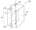
- FIG. 1 It is a perspective view which shows the cooling air path and air path opening part of the power supply device of FIG.
- the embodiment described below exemplifies a vehicle-mounted power supply device and a vehicle equipped with the power supply device for embodying the technical idea of the present invention
- the present invention is a vehicle-mounted power supply device and power supply.
- the vehicle provided with the device is not specified as follows.
- the dimensions, materials, shapes, relative arrangements, and the like of the constituent members described in the embodiments are not intended to limit the scope of the present invention only to the description unless otherwise specified. It is just an example. Note that the size, positional relationship, and the like of the members shown in each drawing may be exaggerated for clarity of explanation.
- each element constituting the present invention may be configured such that a plurality of elements are constituted by the same member and the plurality of elements are shared by one member, and conversely, the function of one member is constituted by a plurality of members. It can also be realized by sharing.
- the contents described in some examples and embodiments may be used in other examples and embodiments.
- FIG. 1 is a perspective view of a power supply apparatus 100 according to Embodiment 1 of the present invention
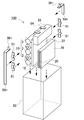
- FIG. 2 is an exploded perspective view of the power supply apparatus 100
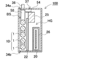
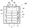
- FIG. 3 and FIG. 4 are cross-sectional views of the internal structure of the power supply apparatus 100.
- a power supply device 100 shown in these drawings includes a battery block 10 composed of a plurality of secondary batteries 1, a circuit board 20 electrically connected to the battery block 10, and the plurality of secondary batteries 1 and a circuit board. 20, and a pair of output terminals 36 for outputting the total voltage of the battery block 10.
- the storage case 30 is indicated by a broken line to show the internal structure of the power supply device 100.
- the storage case 30 has a rectangular outer shape.
- the storage case 30 is preferably made of a material having excellent insulating properties, for example, resin.
- a plurality of secondary batteries 1 and a circuit board 20 are stored in the storage case 30.
- the output terminal 36 includes a positive output terminal 36+ connected to the positive side of the total voltage of the battery block 10 and a negative output terminal 36- connected to the negative side. Further, as shown in the vertical sectional view of FIG. 4, the positive output terminal 36+ is connected to the inside of the storage case 30, and the positive lead plate 50+ and the negative output terminal 36- are connected to the negative lead plate 50-, respectively. ing. Further, a bus bar 54 for wiring a battery block 10, a switching unit 25, and the like, which will be described later, is provided above the storage case 30.
- a hole 37 for venting gas is opened on the upper surface of the storage case 30. This is a hole 37 for discharging gas from the storage case 30 so that the inside of the storage case 30 does not become excessively high pressure when the secondary battery 1 discharges gas.
- the gas discharge hole 37 is preferably connected with a duct for safely discharging the gas discharged from here to the outside of the vehicle.
- the battery block 10 includes a negative electrode side connection terminal 12 positioned on the lower surface side in the storage case 30 and a positive electrode side connection terminal 14 positioned on the upper surface side in the storage case 30.
- the negative output terminal 36- is positioned on the upper surface side of the storage case 30 and is connected to the negative connection terminal 12 positioned on the lower surface side of the storage case 30 by the negative lead plate 50-.
- the positive output terminal 36+ is connected to the positive output terminal by the positive lead plate 50+.
- the positive lead plate 50+ is shorter than the negative lead plate 50-.
- the battery block 10 has the negative electrode side connection terminal 12 grounded. (Secondary battery 1)
- the secondary battery 1 is a member that can store electricity, and a secondary battery cell can be suitably used.
- a nickel metal hydride battery can be suitably used.
- the power supply voltage of the nickel metal hydride battery is 1.2V, it becomes 12V when 10 nickel metal hydride batteries are connected in series, and is suitable for parallel connection with a lead battery PB having a power supply voltage of 12V.
- the secondary battery 1 which is two nickel metal hydride batteries is arranged as a secondary battery set 2 connected in the longitudinal direction, and five sets thereof are arranged in parallel on the same plane.
- a battery block 10 is configured. That is, the battery block 10 is composed of ten nickel metal hydride batteries.
- the voltage of the power supply device 100 can be adjusted to match that of the lead battery of the connection destination.
- a lead battery having a rated voltage of 24V such as a large vehicle such as a truck, can be made to support 24V by connecting 20 secondary batteries 1 of nickel-metal hydride batteries in series.
- the output voltage can be adjusted in multiples of 12V by connecting nickel hydrogen batteries such as 36V, 48V, etc. in units of 10 units, that is, 10n (n is a natural number) in series. Adaptable to the power supply voltage.
- nickel metal hydride batteries can be connected to adjust the total voltage of the battery block in increments of 1.2V.
- nickel-metal hydride batteries may be connected in parallel, thereby increasing the electric capacity of the power supply device.
- the secondary battery set 2 is configured by connecting the two secondary batteries 1 in the longitudinal direction, so that there is no secondary battery sandwiched between the secondary batteries 1, and each secondary battery 1 Since one of the end faces of the battery 1 is necessarily an open face where no other secondary battery exists, heat dissipation from this face can be ensured. Further, by disposing this surface so as to face the side surface of the storage case 30, heat dissipation can be further improved.
- the secondary battery 1 uses a cylindrical outer can.
- a plurality of cylindrical secondary batteries 1 are held in a horizontal posture and are arranged in a planar shape along the inner surface of the storage case 30.
- the battery blocks 10 are arranged in a row and along one main surface (the left main surface in FIG. 3) of the storage case 30, this main surface can be used as a heat dissipation surface of the secondary battery 1.
- the circuit board 20 by disposing the circuit board 20 on the other main surface (the main surface on the right side in FIG. 3), the battery block 10 serving as a heat generation source and the circuit board 20 are separated from each other, and the secondary battery 1 generates heat. A situation that affects the circuit board 20 can be reduced. (Cooling air passage 31)
- a cooling air passage 31 for flowing cooling air is formed as shown in FIG.
- an air passage opening 34 communicating with the cooling air passage 31 is opened on the surface of the storage case 30.
- the air passage openings 34 are respectively opened on opposing surfaces of the storage case 30.
- one air passage opening 34a serves as an inlet for the cooling air passage 31
- the other air passage opening 34b serves as an outlet for cooling air.
- the air passage openings 34a and 34b are opened at positions facing the cooling air passage 31 as shown in FIG. With this configuration, the cooling air guided from the air passage opening 34a can be straightly guided to the cooling air passage 31 and discharged from the other air passage opening 34b.
- the cooling air introduced into the cooling air passage 31 can be smoothly exchanged with the secondary battery 1 without bending the traveling direction of the cooling air inside the storage case 30.
- FIG. 5 in order to show the cooling air passage 31 and the air passage opening 34 b on the back surface side in an easy-to-understand manner, members such as a secondary battery inside the storage case 30 are not shown. Further, the flow of the cooling air is indicated by a one-dot chain line.
- the battery block demonstrated the example which arranges a secondary battery on the same plane in the above example, it can also be arrange
- the battery block demonstrated the example which arranges a secondary battery on the same plane in the above example, it can also be arrange
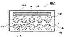
- two battery blocks 10A and 10B configured by a set of five secondary batteries may be stacked in the storage case 30B.
- the cooling air passage 31B can be formed between the battery blocks.
- the battery blocks 10A and 10B arranged on both sides of the one cooling air passage 31B can be efficiently cooled at the same time.
- the surface of the outer can of the secondary battery 1 may be covered with the covering portion 32 as shown in FIG.
- the storage case cannot have a sealed structure, so that dust and water droplets may enter the storage case.
- the covering portion 32 covers the surface of the secondary battery 1 that faces the cooling air passage 31B. That is, in the cross-sectional view of FIG. 6, the first battery block 10A and the second battery block 10B are formed so as to form the cooling air passage 31B between the upper first battery block 10A and the lower second battery block 10B. Each surface is covered with a covering portion 32.
- the covering portion 32 By forming the covering portion 32 with an insulating member, the surface of the secondary battery 1 is not directly exposed to the cooling air passage 31B, but is insulated. Moreover, the coating
- the storage case 30 defines the cooling air passage 31 ⁇ / b> B with the covering portion 32 therein.
- the covering portion 32 is preferably formed integrally with the storage case 30.
- a power storage holder that holds the secondary battery can be formed, a covering portion can be provided on a part of the power storage holder, and the power storage holder can be stored in a storage case.
- FIG. 7 shows a schematic diagram of an example in which the power supply device 100 is installed in an engine room of a vehicle.
- the vehicle shown in the figure includes a traveling engine 96, a radiator 99 that circulates a refrigerant for cooling the engine 96, and a cooling fan 98 that forcibly blows air toward the radiator 99.
- the power supply device 100 is arranged on the air path that is blown by the cooling fan 98 for the radiator.
- the cooling fan 98 for the radiator is provided by arranging the air passage opening so as to intersect with the air passage and the cooling air passage 31 so as to coincide with the cooling air blowing direction of the cooling fan 98. This can be shared for cooling the secondary battery of the power supply device 100. As a result, it is possible to efficiently cool the power supply device using existing equipment without separately preparing a dedicated fan for cooling the secondary battery. (Circuit board 20)
- the circuit board 20 is disposed between the battery block 10 and the main surface of the storage case 30.
- the circuit board 20 is mounted with an electronic circuit that monitors charging / discharging of the secondary battery 1. Further, the circuit board 20 can be mounted with a safety circuit that monitors the abnormality of each secondary battery 1 based on current, voltage, temperature, etc., and shuts off the abnormality when it is determined to be abnormal. (Switching unit 25)
- the switching unit 25 is a member that is connected to the output of the battery block 10 and switches ON / OFF of the output.
- the switching unit 25 is disposed between the battery block 10 and the lead battery PB in a state where the battery block 10 is connected in parallel with the lead battery PB.
- the switching unit 25 is turned on, the battery block 10 is connected in parallel with the lead battery PB, and when it is turned off, the battery block 10 is disconnected from the circuit.
- Such a switching unit 25 can be a relay or a semiconductor switching element.
- the switching unit 25 serves as a heat generating member that generates heat when energized. (Partition wall 22)
- the interior of the storage case 30 is partitioned by a partition wall 22 as shown in the cross-sectional view of FIG.
- the partition wall 22 is divided into a battery housing space BS in which the battery block 10 is disposed and a heat insulating space HG in which the circuit board 20 is disposed.
- the partition wall 22 is comprised with the member provided with heat insulation.
- the switching unit 25 is preferably disposed above the circuit board 20. Thereby, since the heat generated by the switching unit 25 is transferred upward by natural convection, it is possible to suppress the heat from affecting the circuit board 20 disposed below the switching unit 25.
- the arrangement is not limited to the arrangement example in which the switching unit 25 is disposed substantially above the circuit board 20, and the switching unit 25 may be arranged to be offset from the circuit board 20 as in the power supply device 100 illustrated in the cross-sectional view of FIG. 3. preferable.
- the circuit board 20 and the switching unit 25 are arranged diagonally in the heat insulating space HG. By arranging in this way, the circuit board 20 can be separated as much as possible from the switching unit 25 in a limited space, and the influence of heat generated from the switching unit 25 can be further suppressed. (Circuit enclosure 26)
- the circuit board 20 can also cover the periphery thereof.
- the circuit board 20 and the periphery are surrounded by a circuit surrounding plate 26.
- the circuit surrounding plate 26 is formed of a member having heat insulation properties. By providing the heat insulating circuit surrounding plate 26 in this way, the battery block 10 and the circuit board 20 are physically separated from each other, and heat generated by the secondary battery 1 is prevented from reaching the circuit board 20.
- the substrate 20 can be protected.
- the substrate surrounding plate may be omitted and also used as the partition wall.
- the partition wall can be extended so that the inside of the storage case is completely partitioned, physically separated from the battery block, and the circuit board can be protected by the partition wall. (Horizontal position)
- the battery block 10 holds each secondary battery 1 in a horizontal orientation as shown in the vertical sectional view of FIG.
- the horizontal orientation means a direction that is substantially parallel to the water surface when water accumulates in the storage case 30.
- the secondary battery 1 is connected in the longitudinal direction to constitute the secondary battery set 2.
- the battery block 10 is comprised so that the secondary battery group 2 may be piled up in the orthogonal
- each secondary battery set is positioned at the lower part of the storage case. In this state, if water accumulates on the bottom surface of the storage case for some reason, the terminals of each secondary battery set may be submerged, causing an unintended short circuit.
- each secondary battery is set in the horizontal orientation, so that the number of secondary batteries to be submerged can be minimized even if water is collected in the storage case 30. It becomes possible. That is, as shown in the cross-sectional view of FIG. 4, the secondary battery sets 2 constituting the battery block 10 are arranged in the vertical direction in the horizontal posture, so that both ends of the secondary battery set positioned on the bottom surface. Only the submerged state. In this state, even if a short circuit occurs, the potential difference of two secondary batteries is sufficient. For example, when a 1.2 V nickel-metal hydride battery is used, the voltage difference is 2.4 V, and the short circuit current can be reduced.
- each secondary battery 1 is arranged in a horizontal orientation in the storage case having the gas discharge opening. As a result, the gas discharged from the nickel-metal hydride battery can be safely exhausted to the outside of the storage case while greatly suppressing damage caused by the flood.
- security can be improved by making the secondary battery located in the bottom face side into the negative electrode side among the total voltages of the battery block 10 connected with the output terminal 36.
- the secondary battery set 2 of each layer is connected to the edge of the secondary battery set 2 arranged vertically by the first lead plate 51.
- the first lead plate 51 allows the secondary battery sets 2 to be conducted at the shortest distance.
- Such a lead plate is composed of a metal plate having excellent conductivity.
- the total voltage of the battery block 10 is connected to the output terminal 36 through the positive lead plate 50+ and the negative lead plate 50-.
- the positive side of the battery blocks 10 connected in series is connected to the positive side output terminal 36+ via the positive side lead plate 50+
- the negative side of the battery block 10 is connected to the negative side.
- the lead plate 50- is connected to the negative output terminal 36-.
- the lowermost layer of the edges of the secondary battery in which the total voltage of the battery block 10 appears is connected to the negative lead plate 50-. That is, in the arrangement of the secondary batteries shown in FIG.
- the edge of the lower right secondary battery among the upper left edge and the lower right edge of the battery block 10 is connected to the negative lead plate 50-
- the edge of the secondary battery is connected to the positive lead plate 50+.
- the positive electrode side lead plate 50+ is disposed at the uppermost layer, that is, the highest position of the battery block 10, even if the positive electrode lead plate 50+ may be submerged in the storage case 30, there is a relative possibility that this portion will be short-circuited. The safety can be improved.
- the output terminal 36 is provided on the upper surface of the storage case 30, that is, at the highest position of the storage case 30, an effect of reducing the possibility of short-circuiting between the output terminals 36 is obtained.
- the bus bar 54 is also arranged at the upper part of the storage case 30, the risk of this part being submerged due to flooding can be reduced, leading to improved reliability and stability.
- the length of the positive electrode side lead plate 50+ can be made considerably shorter than that of the negative lead plate 50-, so that the risk of short-circuiting is reduced by reducing the exposed area. It leads to what can be done.
- the negative lead plate 50- It is desirable to arrange an insulating member such as an insulating sheet between them.
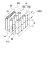
- a power supply device 100C according to such a modification is shown in the perspective view of FIG.
- two rows of battery blocks 10A and 10B are provided, and each of the battery blocks 10A and 10B is placed along the opposing main surface of the storage case 30C, and the battery blocks 10 are separated from each other, with a cooling air passage 31C interposed therebetween. Is provided.
- one of the two rows of battery blocks 10 is opposed to the inner surface of one main surface of the storage case 30C, and the other battery block 10 is connected to the inner surface side of the battery block 10 and the other main surface of the storage case 30C.
- the circuit board 20 is disposed between the two. By arranging in this way, the cooling air passage 31C and the circuit board 20 are separated from each other, and the situation where the circuit board 20 prevents the introduction of the cooling air is avoided.
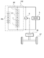
- FIG. 8 shows an example in which the above power supply device 100 is connected to a vehicle battery system.
- the vehicle shown in this figure travels by driving wheels 97 with an engine 96.
- the power supply device 100 is connected in parallel with the lead battery PB.
- the power supply device 100 functions as a sub battery that assists the lead battery PB.
- the lead battery PB and the power supply device 100 which is a sub-battery are directly connected by the lead wire 50 without going through a current adjustment circuit or the like. Therefore, the voltage of the lead battery PB and the sub battery is always the same voltage.
- the lead battery and the sub battery can be connected in parallel via a switching element such as a relay or a semiconductor switching element, and can be connected in parallel via a diode or the like.
- the lead battery PB is a battery in which 6 cells are connected in series and the rated voltage is 12V. However, the present invention does not specify the rated voltage of the lead battery as 12V. Two lead batteries can be connected in series for a rated voltage of 24V, three lead batteries can be connected in series for 36V, and four lead batteries can be connected in series for 48V. Because. Conventional electrical equipment is designed to operate with a power supply voltage of 12V. A vehicle equipped with a lead battery of 24V to 48V is equipped with electrical equipment that operates with this voltage.
- the sub-batteries are connected in parallel in order to improve the charge / discharge efficiency and prevent the lead battery PB from deteriorating.
- the sub battery is connected in parallel with the lead battery PB and has the same voltage.
- compatibility the current balance of charging / discharging between the sub-battery and the lead battery PB, that is, compatibility is important. If the compatibility is poor, only the lead battery and sub-battery will be charged, or only the lead battery and sub-battery will be discharged, so even if both are connected in parallel, the charge / discharge efficiency cannot be improved. The life of the lead battery cannot be effectively extended.
- the compatibility between the lead battery PB and the sub-battery is realized by controlling the open circuit voltage-discharge depth characteristics of the sub-battery.
- the open circuit voltage-discharge depth characteristic of the sub-battery can be adjusted by, for example, the amount of zinc in the positive electrode in a nickel metal hydride battery.
- the power supply device 100 is disposed beside the lead battery PB and is housed in the engine room of the vehicle. Since the power supply device 100 is used in a high-temperature environment such as an engine room, the electrolyte solution of the nickel-metal hydride battery of the secondary battery 2 is any one of a tongue stem compound, a molybdenum compound, and a niobium compound in order to obtain high-temperature durability performance. Contains the above compounds. With this configuration, in addition to high output (low resistance), it is possible to provide the power supply apparatus 100 having high-temperature durability that can withstand even when installed in an engine room.
- the battery system described above can improve fuel efficiency even in a vehicle that is charged by driving the alternator 6 with the engine 96 regardless of regenerative braking. This is because the power supply device 100 that is a sub-battery can be charged up to eight times as much power as the lead battery PB.
- the alternator 6 of the vehicle stabilizes the output voltage at a constant voltage of about 14 V in order to prevent the deterioration by charging the lead battery PB with a constant voltage and to keep the supply voltage of the electrical equipment 5 constant. ing. Therefore, the current for the alternator 6 to charge the lead battery PB is small and is not charged with a large current.
- the alternator 6 does not charge the lead battery PB at 100 A, and the alternator 6 outputs the output current to supply power to the electrical equipment 5.
- the ability of the alternator 6 to charge the battery system with a large current is effective in improving the fuel efficiency of the vehicle. This is because the alternator 6 can be operated in a region where the power generation efficiency is high, and the engine 96 can also be operated in a region where the fuel consumption rate is small. This is because the alternator 6 has low power generation efficiency at light loads, and the engine 96 has a high fuel consumption rate at light loads.
- the regenerative braking generated power is charged not only in the lead battery PB but also in the power supply device 100 to protect the lead battery PB from high-current charging, and the alternator 6
- power is supplied to the electrical equipment 5 from the charged power supply device 100 as well as the lead battery PB, so that the lead battery PB can be prevented from being charged and overdischarged, and the life can be extended.
- the vehicle power supply device and the vehicle including the power supply device according to the present invention can be suitably used for a vehicle battery or an auxiliary battery.
- the load of the lead battery can be reduced.
Landscapes
- Engineering & Computer Science (AREA)
- Chemical & Material Sciences (AREA)
- Chemical Kinetics & Catalysis (AREA)
- Electrochemistry (AREA)
- General Chemical & Material Sciences (AREA)
- Manufacturing & Machinery (AREA)
- Sustainable Development (AREA)
- Life Sciences & Earth Sciences (AREA)
- Sustainable Energy (AREA)
- Power Engineering (AREA)
- Transportation (AREA)
- Mechanical Engineering (AREA)
- Microelectronics & Electronic Packaging (AREA)
- Aviation & Aerospace Engineering (AREA)
- Battery Mounting, Suspending (AREA)
- Secondary Cells (AREA)
Abstract
Description
(実施の形態1)
(収納ケース30)
(二次電池1)
(冷却風路31)
(被覆部32)
(回路基板20)
(スイッチング部25)
(仕切壁22)
(回路包囲板26)
(横置き姿勢)
(第一リード板51)
(回路図)
1…二次電池
2…二次電池組
5…電装機器
6…オルタネータ
10、10A、10B…電池ブロック
12…負極側接続端子
14…正極側接続端子
20…回路基板
22…仕切壁
25…スイッチング部
26…基板包囲板
30、30B、30C…収納ケース
31、31B、31C…冷却風路
32…被覆部
34、34a、34b…風路開口部
36…出力端子;36+…正極側出力端子;36-…負極側出力端子
37…ガス排出孔
50…リード線
50+…正極側リード板
50-…負極側リード板
51…第一リード板
54…バスバー
96…エンジン
97…車輪
98…冷却ファン
99…ラジエータ
PB…鉛バッテリ
HG…断熱空間
BS…電池収納空間
Claims (11)
- 12Vの鉛バッテリと並列に接続可能な車載用の電源装置であって、
充放電可能な複数の二次電池で構成された電池ブロックと、
前記電池ブロックの充放電を制御する電子回路を実装した回路基板と、
前記電池ブロック及び前記回路基板を収納する収納ケースと
を備え、
前記電池ブロックは、
前記二次電池として、ニッケル水素電池をN個(Nは自然数)、直列に接続して構成されてなることを特徴とする車載用の電源装置。 - 請求項1に記載の車載用の電源装置であって、
前記ニッケル水素電池を、10n(nはNより小さい自然数)個、直列に接続して電池ブロックを構成してなることを特徴とする車載用の電源装置。 - 請求項2に記載の車載用の電源装置であって、
前記ニッケル水素電池を、10個、直列に接続して電池ブロックを構成してなることを特徴とする車載用の電源装置。 - 請求項1から3のいずれか一に記載の車載用の電源装置であって、
前記収納ケース内に、前記電池ブロックの収納空間と、前記回路基板の収納空間とを区画する、断熱性の仕切壁を設けてなることを特徴とする車載用の電源装置。 - 請求項4に記載の車載用の電源装置であって、
前記収納ケースは、前記仕切壁で区画された電池収納空間に冷却空気を送風するための冷却風路を形成しており、
さらに前記収納ケースの外部には、前記冷却風路と連通される風路開口部を形成してなることを特徴とする車載用の電源装置。 - 請求項1から5のいずれか一に記載の車載用の電源装置であって、
前記ニッケル水素電池は、円筒形の外装ケースを有しており、
前記収納ケースの内部で、前記複数の円筒形ニッケル水素電池の表面に沿って曲面状に被覆部を形成してなることを特徴とする車載用の電源装置。 - 請求項1から5のいずれか一に記載の車載用の電源装置であって、
前記ニッケル水素電池が、前記収納ケース内にあって、それぞれ水平姿勢に保持されてなることを特徴とする車載用の電源装置。 - 請求項1から7のいずれか一に記載の車載用の電源装置であって、
アイドリングストップの車両に搭載可能であり、車両の回生発電の電力でもって、鉛バッテリと車両用電源装置の両方を充電可能としてなることを特徴とする車載用の電源装置。 - 請求項1から8のいずれか一に記載の電源装置を備える車両であって、
走行用のエンジンと、
前記走行用のエンジンを冷却するためのラジエータと、
前記ラジエータに向けて強制送風する冷却ファンと
を備え、
前記冷却風路は、前記冷却ファンの風路上に配置されてなることを特徴とする車両。 - 請求項1から8のいずれか一に記載の電源装置を備える車両であって、
車両を走行させるエンジンと、
前記エンジンで駆動され、かつ車両の回生制動で駆動されるオルタネータと
を備え、
前記オルタネータで、回生制動時に電源装置を充電するアイドリングストップ機能を有することを特徴とする車両。 - 請求項1から8のいずれか一に記載の電源装置を備える車両であって、
電源装置は、エンジンルームに配置されることを特徴とする車両。
Priority Applications (2)
| Application Number | Priority Date | Filing Date | Title |
|---|---|---|---|
| US14/435,602 US20150343919A1 (en) | 2012-10-29 | 2013-10-24 | Vehicle-mounted power supply device and vehicle comprising power supply device |
| JP2014544266A JPWO2014068922A1 (ja) | 2012-10-29 | 2013-10-24 | 車載用の電源装置及び電源装置を備える車両 |
Applications Claiming Priority (2)
| Application Number | Priority Date | Filing Date | Title |
|---|---|---|---|
| JP2012-238125 | 2012-10-29 | ||
| JP2012238125 | 2012-10-29 |
Publications (1)
| Publication Number | Publication Date |
|---|---|
| WO2014068922A1 true WO2014068922A1 (ja) | 2014-05-08 |
Family
ID=50626872
Family Applications (1)
| Application Number | Title | Priority Date | Filing Date |
|---|---|---|---|
| PCT/JP2013/006302 Ceased WO2014068922A1 (ja) | 2012-10-29 | 2013-10-24 | 車載用の電源装置及び電源装置を備える車両 |
Country Status (3)
| Country | Link |
|---|---|
| US (1) | US20150343919A1 (ja) |
| JP (1) | JPWO2014068922A1 (ja) |
| WO (1) | WO2014068922A1 (ja) |
Cited By (6)
| Publication number | Priority date | Publication date | Assignee | Title |
|---|---|---|---|---|
| WO2018070310A1 (ja) * | 2016-10-14 | 2018-04-19 | 株式会社デンソー | 電池装置 |
| JP2018067533A (ja) * | 2016-10-14 | 2018-04-26 | 株式会社デンソー | 電池装置 |
| JP2019125477A (ja) * | 2018-01-16 | 2019-07-25 | 株式会社オートネットワーク技術研究所 | 外部接続バスバーの接続構造および外部接続バスバーの接続方法 |
| WO2019146314A1 (ja) * | 2018-01-25 | 2019-08-01 | 日立オートモティブシステムズ株式会社 | 二次電池モジュール |
| CN113410560A (zh) * | 2020-03-16 | 2021-09-17 | 本田技研工业株式会社 | 车辆驱动用蓄电池装置 |
| JP2023535359A (ja) * | 2020-07-27 | 2023-08-17 | リマテック | モジュール式直列接続バッテリパック(BlMoSe) |
Families Citing this family (8)
| Publication number | Priority date | Publication date | Assignee | Title |
|---|---|---|---|---|
| JP6497585B2 (ja) * | 2015-06-01 | 2019-04-10 | 株式会社Gsユアサ | 電源装置 |
| WO2018174269A1 (ja) * | 2017-03-23 | 2018-09-27 | 株式会社 東芝 | 非水電解質電池、電池パック及び電池システム |
| TWI649915B (zh) * | 2018-01-02 | 2019-02-01 | 車王電子股份有限公司 | Battery pack |
| CN110034344A (zh) * | 2018-01-12 | 2019-07-19 | 车王电子股份有限公司 | 电池包 |
| DE102018103713A1 (de) * | 2018-02-20 | 2019-08-22 | Dr. Ing. H.C. F. Porsche Aktiengesellschaft | Mechanisches und thermisches System für eine modulare Batterie mit Leistungselektronikkomponenten |
| CN110228359B (zh) * | 2019-06-18 | 2024-12-24 | 哈尔滨沥海佳源科技发展有限公司 | 混合动力汽车的一体化电驱系统 |
| US12191528B2 (en) * | 2020-03-11 | 2025-01-07 | Dongguan Nvt Technology Limited | Battery and electronic device including the same |
| CN115968172B (zh) * | 2022-12-20 | 2026-05-08 | 湖北亿纬动力有限公司 | 一种高压控制盒、高压控制系统及储能系统 |
Citations (7)
| Publication number | Priority date | Publication date | Assignee | Title |
|---|---|---|---|---|
| JPH08264172A (ja) * | 1995-03-24 | 1996-10-11 | Yuasa Corp | ニッケル水素蓄電池 |
| JPH09177552A (ja) * | 1995-12-21 | 1997-07-08 | Kanto Auto Works Ltd | 自動車のバッテリ冷却装置 |
| JP2002304974A (ja) * | 2001-04-05 | 2002-10-18 | Hitachi Ltd | 電池パック |
| JP2003036826A (ja) * | 2001-07-19 | 2003-02-07 | Hitachi Maxell Ltd | 二次電池で駆動可能な情報処理装置 |
| JP2004047279A (ja) * | 2002-07-12 | 2004-02-12 | Shin Kobe Electric Mach Co Ltd | 電池状態検知システム及び該システムを備えた自動車 |
| JP2009126395A (ja) * | 2007-11-26 | 2009-06-11 | Nissan Motor Co Ltd | 車両の制御装置 |
| JP2011015516A (ja) * | 2009-07-01 | 2011-01-20 | Denso Corp | 車載電源装置 |
Family Cites Families (5)
| Publication number | Priority date | Publication date | Assignee | Title |
|---|---|---|---|---|
| JP4636815B2 (ja) * | 2004-05-26 | 2011-02-23 | 三洋電機株式会社 | 車両用の電源装置 |
| US7683582B2 (en) * | 2005-07-28 | 2010-03-23 | Ford Global Technologies, Llc | System and method for thermal management of a vehicle power source |
| US7834582B2 (en) * | 2006-05-11 | 2010-11-16 | Gm Global Technology Operations, Inc. | Method and apparatus for controlling vehicle battery charging |
| ATE522002T1 (de) * | 2006-05-11 | 2011-09-15 | Hoppecke Batterien Gmbh & Co Kg | Akkumulatoranordnung |
| US8963481B2 (en) * | 2011-05-25 | 2015-02-24 | Green Charge Networks | Charging service vehicles and methods using modular batteries |
-
2013
- 2013-10-24 JP JP2014544266A patent/JPWO2014068922A1/ja active Pending
- 2013-10-24 WO PCT/JP2013/006302 patent/WO2014068922A1/ja not_active Ceased
- 2013-10-24 US US14/435,602 patent/US20150343919A1/en not_active Abandoned
Patent Citations (7)
| Publication number | Priority date | Publication date | Assignee | Title |
|---|---|---|---|---|
| JPH08264172A (ja) * | 1995-03-24 | 1996-10-11 | Yuasa Corp | ニッケル水素蓄電池 |
| JPH09177552A (ja) * | 1995-12-21 | 1997-07-08 | Kanto Auto Works Ltd | 自動車のバッテリ冷却装置 |
| JP2002304974A (ja) * | 2001-04-05 | 2002-10-18 | Hitachi Ltd | 電池パック |
| JP2003036826A (ja) * | 2001-07-19 | 2003-02-07 | Hitachi Maxell Ltd | 二次電池で駆動可能な情報処理装置 |
| JP2004047279A (ja) * | 2002-07-12 | 2004-02-12 | Shin Kobe Electric Mach Co Ltd | 電池状態検知システム及び該システムを備えた自動車 |
| JP2009126395A (ja) * | 2007-11-26 | 2009-06-11 | Nissan Motor Co Ltd | 車両の制御装置 |
| JP2011015516A (ja) * | 2009-07-01 | 2011-01-20 | Denso Corp | 車載電源装置 |
Cited By (10)
| Publication number | Priority date | Publication date | Assignee | Title |
|---|---|---|---|---|
| WO2018070310A1 (ja) * | 2016-10-14 | 2018-04-19 | 株式会社デンソー | 電池装置 |
| JP2018067533A (ja) * | 2016-10-14 | 2018-04-26 | 株式会社デンソー | 電池装置 |
| JP2020021751A (ja) * | 2016-10-14 | 2020-02-06 | 株式会社デンソー | 電池装置 |
| JP2019125477A (ja) * | 2018-01-16 | 2019-07-25 | 株式会社オートネットワーク技術研究所 | 外部接続バスバーの接続構造および外部接続バスバーの接続方法 |
| WO2019146314A1 (ja) * | 2018-01-25 | 2019-08-01 | 日立オートモティブシステムズ株式会社 | 二次電池モジュール |
| JP2019129077A (ja) * | 2018-01-25 | 2019-08-01 | 日立オートモティブシステムズ株式会社 | 二次電池モジュール |
| JP7074486B2 (ja) | 2018-01-25 | 2022-05-24 | ビークルエナジージャパン株式会社 | 二次電池モジュール |
| CN113410560A (zh) * | 2020-03-16 | 2021-09-17 | 本田技研工业株式会社 | 车辆驱动用蓄电池装置 |
| CN113410560B (zh) * | 2020-03-16 | 2024-03-26 | 本田技研工业株式会社 | 车辆驱动用蓄电池装置 |
| JP2023535359A (ja) * | 2020-07-27 | 2023-08-17 | リマテック | モジュール式直列接続バッテリパック(BlMoSe) |
Also Published As
| Publication number | Publication date |
|---|---|
| JPWO2014068922A1 (ja) | 2016-09-08 |
| US20150343919A1 (en) | 2015-12-03 |
Similar Documents
| Publication | Publication Date | Title |
|---|---|---|
| JPWO2014068922A1 (ja) | 車載用の電源装置及び電源装置を備える車両 | |
| US12286003B2 (en) | Battery cooling arrangement in an underbody of a vehicle | |
| EP2816632B1 (en) | Casing for an energy storage apparatus with flexible partitioning | |
| KR101182427B1 (ko) | 배터리 팩 및 이를 구비하는 자동차 | |
| JPWO2014068897A1 (ja) | 電源装置及び電源装置を備える車両並びに蓄電装置、バッテリシステム | |
| US9614210B2 (en) | Battery module vent system and method | |
| CN109845024B (zh) | 电池系统和包括其的电动车辆 | |
| US12512529B2 (en) | Air-cooled battery pack for electric vehicle | |
| JP2019525397A (ja) | 電池サブモジュールキャリア、電池サブモジュール、電池システムおよび自動車 | |
| US11695282B2 (en) | Battery device | |
| JP2011175743A (ja) | 電源装置及びこれを備える車両 | |
| JP2025504497A (ja) | 電池及び電力消費機器 | |
| JP2019525398A (ja) | 電池モジュールキャリア、電池モジュール、および電池システムを含む自動車 | |
| WO2013031614A1 (ja) | 電源装置及びこれを備える車両並びに蓄電装置 | |
| JP2014089839A (ja) | 電源装置及び電源装置を備える車両 | |
| JP2012033419A (ja) | 電源装置及びこれを用いた車両、電池セル及び電池セルの製造方法 | |
| JPWO2014068880A1 (ja) | 電源装置及び電源装置を備える車両 | |
| WO2014068881A1 (ja) | 電源装置及び電源装置を備える車両 | |
| WO2014068899A1 (ja) | 電源装置及び電源装置を備える車両並びに蓄電装置、バッテリシステム | |
| WO2013187280A1 (ja) | 車載用の電装用バッテリ | |
| JP2018037244A (ja) | 電源装置及びこれを備える車両 | |
| WO2014010437A1 (ja) | 電源装置及びこの電源装置を備える車両 | |
| JP2023539707A (ja) | 電池の筐体、電池、電力使用機器、電池を製造する方法と機器 | |
| KR102848029B1 (ko) | 배터리의 케이스 바디, 배터리, 전기 설비, 배터리의 제조 방법 및 제조 설비 | |
| KR20230041072A (ko) | 배터리, 전기 설비, 배터리의 제조 방법 및 제조 설비 |
Legal Events
| Date | Code | Title | Description |
|---|---|---|---|
| 121 | Ep: the epo has been informed by wipo that ep was designated in this application |
Ref document number: 13851950 Country of ref document: EP Kind code of ref document: A1 |
|
| WWE | Wipo information: entry into national phase |
Ref document number: 14435602 Country of ref document: US |
|
| ENP | Entry into the national phase |
Ref document number: 2014544266 Country of ref document: JP Kind code of ref document: A |
|
| NENP | Non-entry into the national phase |
Ref country code: DE |
|
| 122 | Ep: pct application non-entry in european phase |
Ref document number: 13851950 Country of ref document: EP Kind code of ref document: A1 |