EP2816632B1 - Casing for an energy storage apparatus with flexible partitioning - Google Patents
Casing for an energy storage apparatus with flexible partitioning Download PDFInfo
- Publication number
- EP2816632B1 EP2816632B1 EP14171274.5A EP14171274A EP2816632B1 EP 2816632 B1 EP2816632 B1 EP 2816632B1 EP 14171274 A EP14171274 A EP 14171274A EP 2816632 B1 EP2816632 B1 EP 2816632B1
- Authority
- EP
- European Patent Office
- Prior art keywords
- energy storage
- partition
- partition plate
- storage devices
- storage apparatus
- Prior art date
- Legal status (The legal status is an assumption and is not a legal conclusion. Google has not performed a legal analysis and makes no representation as to the accuracy of the status listed.)
- Active
Links
Images


Classifications
-
- H—ELECTRICITY
- H01—ELECTRIC ELEMENTS
- H01M—PROCESSES OR MEANS, e.g. BATTERIES, FOR THE DIRECT CONVERSION OF CHEMICAL ENERGY INTO ELECTRICAL ENERGY
- H01M10/00—Secondary cells; Manufacture thereof
- H01M10/60—Heating or cooling; Temperature control
- H01M10/62—Heating or cooling; Temperature control specially adapted for specific applications
- H01M10/625—Vehicles
-
- H—ELECTRICITY
- H01—ELECTRIC ELEMENTS
- H01M—PROCESSES OR MEANS, e.g. BATTERIES, FOR THE DIRECT CONVERSION OF CHEMICAL ENERGY INTO ELECTRICAL ENERGY
- H01M50/00—Constructional details or processes of manufacture of the non-active parts of electrochemical cells other than fuel cells, e.g. hybrid cells
- H01M50/10—Primary casings; Jackets or wrappings
- H01M50/102—Primary casings; Jackets or wrappings characterised by their shape or physical structure
- H01M50/103—Primary casings; Jackets or wrappings characterised by their shape or physical structure prismatic or rectangular
-
- H—ELECTRICITY
- H01—ELECTRIC ELEMENTS
- H01M—PROCESSES OR MEANS, e.g. BATTERIES, FOR THE DIRECT CONVERSION OF CHEMICAL ENERGY INTO ELECTRICAL ENERGY
- H01M10/00—Secondary cells; Manufacture thereof
- H01M10/60—Heating or cooling; Temperature control
- H01M10/61—Types of temperature control
- H01M10/613—Cooling or keeping cold
-
- H—ELECTRICITY
- H01—ELECTRIC ELEMENTS
- H01M—PROCESSES OR MEANS, e.g. BATTERIES, FOR THE DIRECT CONVERSION OF CHEMICAL ENERGY INTO ELECTRICAL ENERGY
- H01M10/00—Secondary cells; Manufacture thereof
- H01M10/60—Heating or cooling; Temperature control
- H01M10/65—Means for temperature control structurally associated with the cells
- H01M10/656—Means for temperature control structurally associated with the cells characterised by the type of heat-exchange fluid
- H01M10/6561—Gases
- H01M10/6563—Gases with forced flow, e.g. by blowers
-
- H—ELECTRICITY
- H01—ELECTRIC ELEMENTS
- H01M—PROCESSES OR MEANS, e.g. BATTERIES, FOR THE DIRECT CONVERSION OF CHEMICAL ENERGY INTO ELECTRICAL ENERGY
- H01M50/00—Constructional details or processes of manufacture of the non-active parts of electrochemical cells other than fuel cells, e.g. hybrid cells
- H01M50/20—Mountings; Secondary casings or frames; Racks, modules or packs; Suspension devices; Shock absorbers; Transport or carrying devices; Holders
- H01M50/204—Racks, modules or packs for multiple batteries or multiple cells
- H01M50/207—Racks, modules or packs for multiple batteries or multiple cells characterised by their shape
- H01M50/209—Racks, modules or packs for multiple batteries or multiple cells characterised by their shape adapted for prismatic or rectangular cells
-
- H—ELECTRICITY
- H01—ELECTRIC ELEMENTS
- H01M—PROCESSES OR MEANS, e.g. BATTERIES, FOR THE DIRECT CONVERSION OF CHEMICAL ENERGY INTO ELECTRICAL ENERGY
- H01M50/00—Constructional details or processes of manufacture of the non-active parts of electrochemical cells other than fuel cells, e.g. hybrid cells
- H01M50/20—Mountings; Secondary casings or frames; Racks, modules or packs; Suspension devices; Shock absorbers; Transport or carrying devices; Holders
- H01M50/289—Mountings; Secondary casings or frames; Racks, modules or packs; Suspension devices; Shock absorbers; Transport or carrying devices; Holders characterised by spacing elements or positioning means within frames, racks or packs
- H01M50/291—Mountings; Secondary casings or frames; Racks, modules or packs; Suspension devices; Shock absorbers; Transport or carrying devices; Holders characterised by spacing elements or positioning means within frames, racks or packs characterised by their shape
-
- Y—GENERAL TAGGING OF NEW TECHNOLOGICAL DEVELOPMENTS; GENERAL TAGGING OF CROSS-SECTIONAL TECHNOLOGIES SPANNING OVER SEVERAL SECTIONS OF THE IPC; TECHNICAL SUBJECTS COVERED BY FORMER USPC CROSS-REFERENCE ART COLLECTIONS [XRACs] AND DIGESTS
- Y02—TECHNOLOGIES OR APPLICATIONS FOR MITIGATION OR ADAPTATION AGAINST CLIMATE CHANGE
- Y02E—REDUCTION OF GREENHOUSE GAS [GHG] EMISSIONS, RELATED TO ENERGY GENERATION, TRANSMISSION OR DISTRIBUTION
- Y02E60/00—Enabling technologies; Technologies with a potential or indirect contribution to GHG emissions mitigation
- Y02E60/10—Energy storage using batteries
-
- Y—GENERAL TAGGING OF NEW TECHNOLOGICAL DEVELOPMENTS; GENERAL TAGGING OF CROSS-SECTIONAL TECHNOLOGIES SPANNING OVER SEVERAL SECTIONS OF THE IPC; TECHNICAL SUBJECTS COVERED BY FORMER USPC CROSS-REFERENCE ART COLLECTIONS [XRACs] AND DIGESTS
- Y02—TECHNOLOGIES OR APPLICATIONS FOR MITIGATION OR ADAPTATION AGAINST CLIMATE CHANGE
- Y02P—CLIMATE CHANGE MITIGATION TECHNOLOGIES IN THE PRODUCTION OR PROCESSING OF GOODS
- Y02P70/00—Climate change mitigation technologies in the production process for final industrial or consumer products
- Y02P70/50—Manufacturing or production processes characterised by the final manufactured product
Definitions
- the present invention relates to an energy storage apparatus including one or more energy storage devices housed in an outer housing.
- Battery packs that include a plurality of energy storage apparatuses housed in a pack case are known.
- the plurality of energy storage apparatuses each include one or more energy storage devices (battery cells) housed in an outer housing (module case).
- Each energy storage apparatus included in the battery pack requires a configuration in which electrical insulation of the battery cells is maintained and heat from the battery cells is prevented from transferring to surrounding components.
- the plurality of battery cells are arranged spaced apart from each other in order to maintain electrical and heat insulation.
- Another energy storage apparatus is known that can further secure electrical and heat insulation when a plurality of battery cells are to be housed in a module case by using partition plates formed between the plurality of battery cells in the module case.
- US 2006/0093899 A1 provides a battery module capable of keeping installation positions of partition walls constant and capable of inducing uniform deformation of the partition walls and a case, by securely fixing the partition walls within the case or by forming the partition walls integrally with the case.
- a battery fixing structure is provided to improve the engaging force between the case and the unit batteries or between the case and the partition walls.
- the partition walls are fixedly installed at predetermined intervals in the case, and the plurality of unit batteries which are separated from each other with the partition walls therebetween to be inserted into the case.
- JP 2003 258462 A provides an electronic apparatus which enables the easy detachment and attachment of small units.
- the electronic apparatus is provided with a casing and a plurality of small units juxtaposed each other in the casing.
- a keyhole for securing the casing to each small unit is formed in the front face of the small unit.
- a key portion of a handle is inserted into the keyhole, whereby a secured status between the small unit and the casing is relieved, the handle and the small unit are secured, and the small unit is drawn out of the casing through the handle.
- An object of the present invention is to provide an energy storage apparatus including an outer housing having increased design flexibility and a configuration that is changeable according to different design requirements.
- An energy storage apparatus includes: one or more energy storage devices, each energy storage device having a side surface; and an outer housing that houses the one or more energy storage devices.
- the outer housing includes an attachment portion for attaching a partition plate adjacently to the side surface of the one or more energy storage devices.
- the configuration of an outer housing can be changed depending on design requirements such as electrical insulation and heat insulation.
- design requirements such as electrical insulation and heat insulation.
- the present invention was conceived in view of the above and aspects of the present invention provide an energy storage apparatus including an outer housing having increased design flexibility and a configuration that is changeable depending on design requirements.
- An energy storage apparatus includes: one or more energy storage devices, each energy storage device having a side surface; and an outer housing that houses the one or more energy storage devices.
- the outer housing includes an attachment portion for attaching a partition plate adjacently to the side surface of the one or more energy storage devices.
- the outer housing includes the attachment portion for attaching the partition plate adjacently to the side surface of the one or more energy storage devices, it is possible to selectively attach the partition plate to the outer housing.
- the partition plate can be selectively installed, or not installed, in the outer housing as needed. In this way, it is possible to flexibly alter the structure of the outer housing to suit the design requirements.
- the outer housing may include: a bottom surface; and a partition portion that extends from the bottom surface and is disposed adjacently to the side surface of the one or more energy storage devices.
- the outer housing may be configured such that the partition plate is disposed on an extension line of the partition portion.
- the outer housing includes the partition portion that extends from the bottom surface and is disposed adjacently to the side surface of the one or more energy storage devices, the one or more energy storage devices can easily be disposed in predetermined locations.
- the partition portion makes it possible to easily determine the positioning of the one or more energy storage devices in the outer housing.
- the partition portion may be continuously formed on the bottom surface and extend from a first side wall of the outer housing to a second side wall of the outer housing, the first and second side walls being opposite from each other and each being continuously formed on the bottom surface and intersecting the bottom surface.
- the partition portion is continuously formed on the bottom surface and extends from the first side wall of the outer housing to the second side wall of the outer housing, even if water from, for example, moisture, builds up on the first surface of the outer housing, it is possible to ensure electrical insulation of the container of the energy storage device and components disposed in the area surrounding the energy storage device (including the energy storage device).
- the attachment portion may include the partition portion, and the partition portion may include, at its tip end, a fitting portion for fitting a first end portion of the partition plate.
- the partition portion includes, in its tip end, a fitting portion for fitting a first end portion of the partition plate, it is possible to easily attach the partition plate to the outer housing simply by inserting the partition plate into the fitting portion of the partition portion.
- the outer housing may have an opening in a surface other than the bottom surface on which the partition portion is formed.
- the opening is formed in the outer housing in a surface thereof other than the bottom surface on which the partition portion is formed. Since the opening is formed in the side wall and not in the vicinity of the partition portion, the strength of the partition portion can be maintained.
- the partition portion may be made of a material different from that of the partition plate.
- the energy storage apparatus may further include the partition plate that is detachably attached to the attachment portion.
- the partition plate since the partition plate is detachably attached to the attachment portion, the partition plate can be attached or detached flexibly as needed.
- the partition plate may include an insulating member.
- the partition plate includes an insulating member, it is possible to insulate the one or more energy storage devices both thermally and electrically.
- the energy storage apparatus may include the plurality of energy storage devices that are arranged in a line, and the attachment portion may be formed between the energy storage devices such that the partition plate is attachable to the attachment portion.
- the partition plate may have a recessed section at its first end portion, and the partition portion may include a protruding section that is engageable with the recessed section, the protruding section being formed in the partition portion.
- the attachment portion may include a support portion in a position where at least one surface of the partition plate in a vicinity of its second end portion is abuttable.
- the support portion may have a groove for fitting a second end portion of the partition plate.
- the energy storage apparatus may further include an abutment member abutting the one or more energy storage devices.
- a second end portion of the partition plate may abut the abutment member.
- the partition plate spans the first axis width of the one or more energy storage devices, it is possible to increase the heat insulation between the one or more energy storage devices and conductive components.
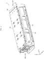
- FIG. 1 is an external perspective view of the energy storage apparatus 1 according to the embodiment of the present invention.
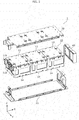
- FIG. 2 is an exploded perspective view illustrating structural components of the energy storage apparatus 1.
- the Z axis which is the first axis, is shown as being the vertical direction in FIG.1 and FIG. 2 .
- the Z axis is exemplified as being the vertical direction in the following description as well, but depending on the mode of use, it is conceivable that the Z axis may be a direction other than the vertical direction. As such, the Z axis is not limited to the vertical direction.
- the energy storage apparatus 1 is an energy storage module capable of charging electricity from an external source and discharging electricity to an external device.
- the energy storage apparatus 1 is, for example, a high-voltage energy storage apparatus used to store energy and/or used as a power source.
- the energy storage apparatus 1 includes a module group 10 including module units 11, 12, and 13, a lower coupling component 20, an upper coupling component 30, and a cooling apparatus 40. It should be noted that the energy storage apparatus 1 may include only one module unit.
- the module units 11, 12, and 13 included in the module group 10 are aligned along the X axis.
- the module unit 11 includes an external positive terminal cover 11a which covers the external positive terminal (to be described later) and an external negative terminal cover 11b which covers the external negative terminal (to be described later).
- the energy storage apparatus 1 charges electricity from an external source and discharges electricity to an external device through the external positive terminal under the external positive terminal cover 11a and the external negative terminal under the external negative terminal cover 11b.
- the module units 11, 12, and 13 are rectangular modules including one or more energy storage devices housed in a module case 14. Each of the module units 11, 12, and 13 has the same configuration. Moreover, the positive terminals and negative terminals of adjacent ones of the module units 11, 12, and 13 are electrically connected, whereby all energy storage devices in the module units 11, 12, and 13 are connected in series. The configuration of the module units 11, 12, and 13 will be described in detail later.
- the lower coupling component 20 and the upper coupling component 30 are components which couple the module units 11, 12, and 13 together.
- the lower coupling component 20 couples the module units 11, 12, and 13 from below and the upper coupling component 30 couples the module units 11, 12, and 13 from above. In other words, fixing the lower coupling component 20 and the upper coupling component 30 together with the module units 11, 12, and 13 disposed therebetween couples the module units 11, 12, and 13 together.
- the lower coupling component 20 and the upper coupling component 30 are plate-like members formed, for example, from a conductive material such as metal. With this, the module units 11, 12, and 13 are firmly and securely fixed. It should be noted that since it is usually difficult to electrically insulate the surfaces of the lower coupling component 20 and the upper coupling component 30 with a coating, the lower coupling component 20 and the upper coupling component 30 have conductive properties.
- each module case 14 of the module units 11, 12, and 13 is mounted on the lower coupling component 20.
- the cooling apparatus 40 is a fan that introduces a coolant into the module group 10.
- the cooling apparatus 40 draws in outside air (the coolant) from the end of the module group 10 in the negative direction of the X axis, and introduces air into each module case 14 of the module units 11, 12, and 13.
- the cooling apparatus 40 then expels the air from the end of the module group 10 in the positive direction of the X axis out the back of the cooling apparatus 40.
- the cooling apparatus 40 may draw in outside air from the end of the module group 10 in the positive direction of the X axis and expel the air from the end of the module group 10 in the negative direction of the X axis.
- the coolant introduced into the module group 10 by the cooling apparatus 40 is not limited to atmospheric air.
- the coolant may be cold air chilled by a condenser.
- the cooling apparatus 40 is provided with two fans, but number of fans the cooling apparatus 40 has is not limited to this example. Still further, the cooling apparatus 40 is not limited to the use of a fan. As long as it introduces the coolant into the module group 10, something other than a fan may be used.
- each of the module units 11, 12, and 13 included in the module group 10 will be described in detail. It should be noted that each of the module units 11, 12, and 13 have the same configuration. As such, the following description focuses on the module unit 11, and descriptions of the module units 12 and 13 are omitted.
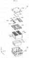
- FIG. 3 is an exploded perspective view illustrating structural components of the module unit 11 according to the embodiment of the present invention.
- the module unit 11 includes: the module case 14 including a case main body 100 and a cover 700; a plurality of energy storage devices 200 (in the embodiment, four of the energy storage devices 200 are provided) housed in the module case 14; a partition plate 140; an abutment member 300; bus bars 430, and a substrate 600.
- the plurality of energy storage devices 200 are aligned along the Y axis, which is the second axis. It should be noted that one energy storage device 200 may be housed in the module case 14 instead of a plurality of the energy storage devices 200.
- the module case 14 is a rectangular (box-shaped) container acting as an outer housing for the module unit 11.
- the module case 14 arranges the energy storage devices 200 and the substrate 600 and such in given positions and protects the energy storage devices 200 and the substrate 600 and such from impact.
- the module case 14 is made of a material having insulating properties, such as a resin, like polycarbonate, for example. This prevents the energy storage device 200 and the substrate 600 and such from coming into contact with, for example, external metal components.
- the module case 14 includes the case main body 100 and the cover 700.
- the case main body 100 is a rectangular, tubular component having a bottom, and serves as the main body of the module case 14.
- the cover 700 is a low-profile, rectangular component that covers the opening of the case main body 100, and serves as the cover of the module case 14.
- the energy storage devices 200, the abutment member 300, and the bus bars 430 are arranged in this order in the case main body 100, and then the opening of the case main body 100 is closed off with the cover 700. Arranging the heavy energy storage devices 200 on the bottom in this way improves the stability of the module unit 11.
- the configuration of the case main body 100 will be described in detail later.
- the partition plate 140 is a flat component disposed between the energy storage devices 200.
- the partition plate 140 is a component having electrical and heat insulating properties, and is formed, for example, by laminating sheets made of resin impregnated with a material such as fiberglass. It should be noted that the partition plate 140 is not limited to the above material, and may be formed of, for example resin that has at least either one of electrical or heat insulating properties.
- the partition plate 140 is a component disposed between the energy storage devices 200 to secure at least one of electrical and heat insulation between the energy storage devices 200. More specifically, the partition plate 140 is attached to an attachment portion 134 (to be described later) provided in the case main body 100.
- the abutment member 300 is a low-profile, rectangular component located above the energy storage devices 200.
- the abutment member 300 is made of a material having insulating properties, such as resin.
- the abutment member 300 is a component that abuts the side of the energy storage devices 200 in the positive direction of the Z axis.
- the abutment member 300 may have a function of restricting the positioning of the energy storage devices 200 included in the case main body 100. More specifically, the abutment member 300 may fit inside the case main body 100 and hold down the energy storage devices 200 from above to fix the energy storage devices 200 to the case main body 100.
- the substrate 600 is mounted on the abutment member 300.
- the abutment member 300 functions as a mounting plate for the substrate 600 in addition to functioning to fix the energy storage devices 200 to the case main body 100.
- the bus bars 430 are arranged above the abutment member 300.
- the bus bars 430 are made of a conductive material, such as metal, and electrically connect the energy storage devices 200 together. More specifically, the bus bar 430 connects the positive terminal or negative terminal of one of two adjacently arranged energy storage devices 200 to the negative terminal or positive terminal of the other of the two adjacently arranged energy storage devices 200.
- the module unit 11 moreover includes an external positive terminal 410 arranged in the external positive terminal cover 11a and an external negative terminal 420 arranged in the external negative terminal cover 11b.
- the external positive terminal 410 and the external negative terminal 420 are electrode terminals for charging the energy storage apparatus 1 with electricity from an external source and discharging electricity to an external device.
- the energy storage apparatus 1 is charged with electricity from an external source and discharges electricity to an external device via the external positive terminal 410 and the external negative terminal 420.
- the substrate 600 is a substrate capable of obtaining, monitoring, and controlling the state of the energy storage devices 200, and is connected to the energy storage devices 200 via wiring 440.
- the wiring 440 is a lead wire connecting the positive terminal 230 or the negative terminal 240 of the energy storage device 200 to the substrate 600. It should be noted that the illustration of the wiring 440 is partially omitted in FIG. 3 .
- the substrate 600 is a control substrate for obtaining and monitoring, for example, the charging state and discharging state (the state of the battery, such as voltage or temperature) of the energy storage devices 200.
- the substrate 600 is provided with a control circuit (not shown in the drawings) for performing the above-described monitoring, controlling the on and off states of a relay, or communicating with other devices.
- the substrate 600 is located on the abutment member 300, and arranged so as to be covered by the cover 700.
- the substrate 600 is arranged so as to be protected by the abutment member 300 and the cover 700 as a result of being sandwiched between the abutment member 300 and the cover 700.
- integrating the electrical components in the upper portion of the energy storage apparatus 1 makes assembly and maintenance of the energy storage apparatus 1 easier.
- FIG. 4 is a transparent perspective view illustrating the inside of the energy storage device 200 according to the embodiment of the present invention.
- FIG. 5 is an external perspective view of the energy storage device 200 from below.
- the energy storage device 200 is a secondary battery (battery cell) capable of charging and discharging electricity. More specifically, the energy storage device 200 is a non-aqueous electrolyte secondary battery such as a lithium ion secondary battery. It should be noted that the energy storage device 200 is not limited to a non-aqueous electrolyte secondary battery. The energy storage device 200 may be a secondary battery other than a non-aqueous electrolyte secondary battery, such as a capacitor.
- the energy storage device 200 includes a container 210, the positive terminal 230, and the negative terminal 240.
- the container 210 includes, as a top wall, a container lid 220. Additionally, an electrode assembly 250, a positive current collector 260, and a negative current collector 270 are arranged in the container 210. It should be noted that even though it is not shown in the drawings, the container 210 contains a liquid such as an electrolyte.
- the container 210 is configured of a rectangular, tubular metal chassis main body having a bottom, and a container lid 220, which is metallic and hermetically seals the opening of the chassis main body. Moreover, after insertion of the electrode assembly 250 and such, the inside of the container 210 is sealed by, for example, welding the container lid 220 to the chassis main body. It should be noted that the material used for the container 210 is not particularly limited to a certain material, but is preferably a weldable metal such as stainless steel or aluminum.
- the container 210 includes a sheet 211 that has insulating properties and covers the battery side surfaces 210a and 210b, and a sheet 212 that has insulating properties and covers the battery bottom surface 210c.
- the battery side surface 210a is the long side surface of the container 210
- the battery side surface 210b is the short side surface of the container 210
- the battery bottom surface 210c is the bottom surface of the container 210.
- the sheet 212 is an insulation sheet that, by covering the battery bottom surface 210c, maintains electrical insulation and protects the battery bottom surface 210c from being scratched.
- the sheet 211 is an insulation sheet that, by covering the battery side surfaces 210a and 210b, which are the side surfaces adjacent to the battery bottom surface 210c, without covering the battery bottom surface 210c, maintains electrical insulation and protects the battery side surfaces 210a and 210b from being scratched.
- a gap is present at the perimeter of the battery bottom surface 210c, at the boundary of the sheet 211 and the sheet 212. It should be noted that the sheet 211 and the sheet 212 are not required to have electrical insulating properties. Even in this case, the sheet 211 and the sheet 212 are effective in preventing scratches.
- the electrode assembly 250 is a power generating element capable of storing electricity, and includes a positive electrode, a negative electrode, and a separator. More specifically, the electrode assembly 250 is a wound electrode assembly formed by winding, into an oblong shape, a laminate including the negative electrode, the positive electrode, and the separator interposed therebetween. It should be noted that the electrode assembly 250 may be a stacked electrode assembly in which flat electrode plates are layered.
- the positive electrode is a long, belt-shaped positive electrode base material foil made of aluminum or an aluminum alloy with a positive electrode active material layer formed on a surface thereof.
- the negative electrode is a long, belt-shaped negative electrode base material foil made of copper or a copper alloy with a negative electrode active material layer formed on a surface thereof.
- the separator is a microporous sheet. It should be noted that the positive electrode, the negative electrode, and the separator used in the energy storage device 200 are not particularly different from conventional positive electrodes, negative electrodes, and separators, and so long as the performance of the energy storage device 200 is not inhibited, well-known materials may be used. Moreover, so long as it does not inhibit the performance of the energy storage device 200, the electrolyte (non-aqueous electrolyte) enclosed in the container 210 is not particular limited to a certain type; a variety of electrolytes may be used.
- the positive terminal 230 is an electrode terminal that is electrically connected to the positive electrode in the electrode assembly 250 via the positive current collector 260
- the negative terminal 240 is an electrode terminal that is electrically connected to the negative electrode in the electrode assembly 250 via the negative current collector 270.
- Both the positive terminal 230 and the negative terminal 240 are connected to the container lid 220.
- the positive terminal 230 and the negative terminal 240 are metallic electrode terminals for leading electricity stored in the electrode assembly 250 out of the energy storage device 200 and introducing electricity into the energy storage device 200 to be stored in the electrode assembly 250.
- the positive terminal 230 of the energy storage device 200 positionally corresponding to the external positive terminal 410 is connected to the external positive terminal 410, and the negative terminal 240 of the same energy storage device 200 is connected to the positive terminal 230 of an adjacent energy storage device 200.
- the negative terminal 240 of the energy storage device 200 positionally corresponding to the external negative terminal 420 is connected to the external negative terminal 420, and the positive terminal 230 of the same energy storage device 200 is connected to the negative terminal 240 of an adjacent energy storage device 200.
- the positive terminal 230 or the negative terminal 240 of other energy storage devices 200 are connected to the negative terminal 240 or the positive terminal 230 of an adjacent energy storage device 200.
- the positive current collector 260 is a rigid component having conductive properties that is electrically connected to the positive terminal 230 and the positive electrode, and positioned between the positive electrode of the electrode assembly 250 and a side wall of the container 210. It should be noted that, similar to the positive electrode current collector foil of the positive electrode, the positive current collector 260 is made of aluminum.
- the negative current collector 270 is a rigid component having conductive properties that is electrically connected to the negative terminal 240 and the negative electrode of the electrode assembly 250, and positioned between the negative electrode of the electrode assembly 250 and a side wall of the container 210. It should be noted that, similar to the negative electrode current collector foil of the negative electrode, the negative current collector 270 is made of copper.
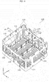
- FIG. 6 is a perspective view illustrating the configuration of the case main body 100 according to the embodiment of the present invention.
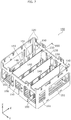
- FIG. 7 is a perspective view illustrating the configuration in which the partition plates 140 are attached to the case main body 100.
- the case main body 100 includes a case bottom portion 110, a case side wall portion 120, and a plurality of partition portions 130, and is a rectangular, tubular component having a bottom and an opening in the upper portion.
- the energy storage devices 200 are inserted through the opening in the upper portion of the case main body 100 and housed in the case main body 100.
- the energy storage devices 200 are housed in the case main body 100 such that the container lid 220 faces upward (the positive direction of the X axis).
- the energy storage devices 200 are housed in the case main body 100 such that the battery bottom surfaces 210c of the energy storage devices 200 are opposed to the case bottom portion 110 and the battery side surfaces 210a and 210b of the energy storage devices 200 are opposed to the case side wall portion 120, the partition portions 130, and the partition plates 140.
- the case bottom portion 110 is the bottom surface of the case main body 100, and is a flat, rectangular component.
- the case side wall portion 120 is a four-cornered tubular component made from four flat, rectangular side walls that cover the four sides of the case bottom portion 110.
- the case main body 100 of the module case 14 includes the case bottom portion 110 as the bottom surface and a plurality of the partition portions 130 that extend from the case bottom portion 110 and are disposed adjacently to the side surfaces of the energy storage devices 200 so as to partition the bottom end portions of the energy storage devices 200.
- the partition portions 130 are flat, rectangular components for partitioning the energy storage devices 200 disposed in the case main body 100.
- Each of the partition portions 130 is continuous from, among the four rectangular, flat side walls of the case side wall portion 120, one of the pair of side walls facing the direction of the X axis to the other.
- partition portions 130 are continuously formed on the bottom surface and extend from a first side wall of the module case 14 to a second side wall of the module case 14, which are opposite from each other.
- the first and second walls are each continuously formed on the bottom surface and intersect the bottom surface.
- each of the pair of side walls has openings 150, and among the four rectangular, flat side walls of the case side wall portion 120, each side wall in the pair of side walls facing the direction of the Y axis has openings 151.
- the case main body 100 includes the attachment portions 134 for attachment of the partition plates 140 to the case main body 100.
- the attachment portions 134 include the partition portions 130.
- Each partition portion 130 includes, at its tip end, as the fitting portion, a groove 131 for fitting the end portion 142 of each partition plate 140.
- the partition portions 130 include, on both side surfaces, protrusions 132.
- the protrusions 132 restrict the positions of the energy storage devices 200 along the Y axis by abutting the battery side surfaces 210a of the energy storage devices 200.
- the protrusions 132 have a function of preventing the partition portions 130 from warping.
- the attachment portions 134 may further include pairs of support portions 133 formed in portions of the case side wall 120 located in the positive direction of the Z axis, from both X axis sides of the partition portions 130.
- the pairs of support portions 133 positionally correspond to respective partition portions 130
- Each support portion 133 has a groove 133a for fitting a protrusion 141, which is a second end portion of the partition plate 140.
- each of the partition plates 140 attaches to the case main body 100 by being inserted and engaging with the groove 131 formed in the partition portion 130 and the groove 133a formed in the support portion 133.
- the support portion 133 may be formed on only one of the two sides facing the direction of the X axis instead of on both sides.
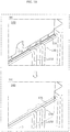
- FIG. 8 is a cross sectional view at the line VIII-VIII illustrated in FIG. 7 of the case main body 100 with the partition plate 140 attached thereto.
- the partition plate 140 includes the pair of protrusions 141 in the end portion in the positive direction of the Z axis.
- the protrusions extend from both sides in the direction of the X axis.
- the partition plate 140 has a plurality of cut-out sections 143 and cut-out sections 144 (recessed sections) at its first end portion.
- the case main body 100 is provided with (i) the support portions 133 including the grooves 133a for engaging the pair of protrusions 141 of the partition plate 140 and (ii) the partition portion 130 including the groove 131 in which the end portion 142 of the partition plate 140 in the negative direction of the Z axis is inserted.
- the partition portion 130 of the case main body 100 includes ridges 131a (protruding sections) for further engagement with the cut-out sections 143 of the partition plate 140.
- the groove 133a formed in the support portion 133 includes a bottom surface 133b that supports the side of the protrusion 141 of the partition plate 140 located in the negative direction of the Z axis.
- the partition plate 140 can also be supported at the protrusion 141 formed at the end portion of the partition plate 140 in the positive direction of the Z axis. This makes it possible to prevent warping where the end portion located on the side of the partition plate 140 in the positive direction of the Z axis moves closer to the end portion located in the negative direction of the Z axis.
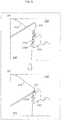
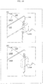
- FIG. 9 is an enlarged view illustrating how the partition plate 140 attaches to the support portion 133 of the case main body 100 according to the embodiment of the present invention.
- FIG. 10 is an enlarged view illustrating how the partition plate 140 attaches to the partition portion 130 of the case main body 100.
- FIG. 9 illustrates the state before the partition plate 140 is inserted into the groove 133a of the support portion 133
- (b) illustrates the state after the partition plate 140 is inserted into the groove 133a of the support portion 133.
- the protrusion 141 of the partition plate 140 slides into the groove 133a of the support portion 133 provided on the case side wall 120 of the case main body 100.
- the partition plate 140 and the groove 133a of the support portion 133 are engaged while the side of the protrusion 141 of the partition plate 140 located in the negative direction of the Z axis abuts the bottom surface 133b of the groove 133a.
- FIG. 10 illustrates the state before the partition plate 140 is inserted into the groove 131 of the partition portion 130
- (b) illustrates the state after the partition plate 140 is inserted into the groove 131 of the partition portion 130.
- the end portion 142 of the partition plate 140 located in the negative direction of the Z axis slides into the groove 131 of the partition portion 130 of the case main body 100.
- the partition plate 140 and the groove 131 of the partition portion 130 are engaged while the end portion 142 of the partition plate 140 abuts the bottom surface of the groove 131.
- the partition plate 140 engages with the grooves 131 and 133a formed in the partition portion 130 and the support portion 133, respectively, which are included in the attachment portion 134 of the case main body 100, to attach to the case main body 100.
- the partition plate 140 is detachably attached to the attachment portion 134 of the case main body 100.
- FIG. 11 is a cross sectional view at the line XI-XI illustrated in FIG. 6 of the case main body 100 with the energy storage devices 200, the partition plates 140, and the abutment member 300 disposed therein.
- the abutment member 300 includes a partition portion 310 that is positioned between the energy storage devices 200 and extends in the negative direction of the Z axis.
- a rectangular protrusion 311 is formed on both side surfaces of the partition portion 310 formed on the abutment member 300, similar to the protrusions 132 of the partition portions 130 formed on the case main body 100.
- the protrusions 311 restrict the positions of the energy storage devices 200 along the Y axis by abutting the battery side surfaces 210a of the energy storage devices 200.
- the protrusions 311 have a function of preventing the partition portions 310 from warping.
- the end portion of the partition plate 140 located in the positive direction of the Z axis extends to the vicinity of the end portion of the partition portion 310 of the abutment member 300 located in the negative direction of the Z axis. It should be noted that the end portion of the partition plate 140 located in the positive direction of the Z axis may abut the end portion of the partition portion 310 of the abutment member 300 located in the negative direction of the Z axis. In this way, since the partition plates 140 are disposed between the energy storage devices 200 across the Z axis direction, electrical and heat insulation between the energy storage devices 200 can be, with certainty, increased. Moreover, by abutting the abutment member 300 with the partition plate 140, the partition plate 140 can easily be secured, and vibration of the partition plate 140 can be prevented.
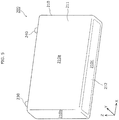
- FIG. 12 is a perspective view illustrating the configuration of a battery pack 2 including the energy storage apparatus 1 according to the embodiment of the present invention.
- the battery pack 2 is a large power source apparatus in which a plurality of energy storage apparatuses 1 (for example, ten to forty) are arranged in an array.
- the battery pack 2 is used to store energy and/or used as a power source, for example.
- the battery pack 2 includes a plurality of the energy storage apparatuses 1 and a pack case 2a that houses the plurality of energy storage apparatuses 1.
- the external positive terminals 410 and external negative terminals 420 of adjacent ones of the energy storage apparatuses 1 are electrically connected together to form the high-voltage battery pack 2. It should be noted that the number of energy storage apparatuses 1 included in the battery pack 2 is not particularly limited to a given number.
- the case main body 100 of the module case 14 is provided with the attachment portions 134 for attaching the partition plates 140 between the energy storage devices 200, it is possible to selectively attach the partition plates 140 to the case main body 100.
- the module case 14 has a structure in which the transfer of heat from the energy storage devices 200 to nearby components (in particular, to an adjacent energy storage device) is inhibited.
- the partition plate 140 has insulating properties, it is possible to improve the insulation of the heat from the energy storage devices 200 and the electrical insulation of the energy storage devices 200.
- partition plates 140 are provided to be detachably attachable to the plurality of pairs of attachment portions 134 in the case main body 100 of the module case 14, it is possible to remove a partition plate 140 as needed with regard to electrical or heat insulation. This makes it possible to increase the design flexibility of the module case 14.
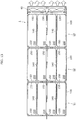
- FIG. 13 is a cross sectional view of the energy storage apparatus 1 at the line XIII-XIII in FIG. 1 , illustrating the flow of air generated by the cooling apparatus 40 when the partition plates are not provided in the center in the Y axis direction.
- the cooling apparatus 40 generates the flow of air along the X axis.
- each side wall in the pair of side walls facing the direction of the X axis among the case side walls 120 of the case main body 100 of each of the module units 11, 12, and 13 have openings 150 for allows air flow generated by the cooling apparatus 40 to pass.
- each side wall in the pair of side walls facing the direction of the Y axis among the case side walls 120 of the case main body 100 has openings 151.
- the case main body 100 has openings 150 and 151 formed in the case side wall portion 120, which is different from the case bottom portion 110 on which the partition portions 130 are formed.
- the plurality of openings 150 provided in the pair of side walls facing the direction of the X axis are formed positionally opposed to each other.
- the openings 150 are also provided corresponding to the positions of the attachment portions 134 for attaching the partition plates 140.
- the flow of air along the X axis generated by the cooling apparatus 40 passes between the energy storage devices 200.
- the drop in pressure when the space is used as the flow path is greater than when the plurality of partition plates 140 are not provided.
- the openings it is possible to form the openings to be large, and especially when a partition plate is not attached to a partition portion, the cooling performance can be markedly increased.
- the case side wall portion 120 has a plurality of openings 150 and 151, but the number is not limited to more than one; advantageous effects can still be achieved even with only one opening.
- the energy storage apparatus 1 it is more difficult to transfer heat to the outside for more inward positioned energy storage devices 200, meaning they are more likely to increase in temperature.
- the two energy storage devices 200 located in the center in the Y axis direction are more prone to increasing in temperature. It is not preferable when some energy storage devices 200 get hotter than other energy storage devices 200 as this leads to a disparity in operation life and storage capacity of the energy storage devices.
- the partition plate 140 is detachably attachable to the attachment portion 134, it is possible to remove only the center partition plate 140 in the Y axis direction.
- FIG. 14 shows a different perspective.
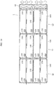
- FIG. 14 is a cross sectional view of the energy storage apparatus 1 at the line XIV-XIV in FIG. 1 , illustrating the flow of air generated by the cooling apparatus 40 when the partition plates 140 are only provided in the center in the Y axis direction.
- the two energy storage devices 200 located in the center in the Y axis direction are more prone to increasing in temperature.
- the partition plate 140 having high heat insulating properties only in the center position in the Y axis direction, heat transfer between these two energy storage devices 200 can be reduced. This makes it possible to reduce the impact of heat exchange between the two energy storage devices 200 located in the center in the Y axis direction that are prone to being high in temperature.
- the case main body 100 of the module case 14 includes the plurality of partition portions 130 formed to partition a portion of the energy storage device 200 in the negative direction of the Z axis, the plurality of energy storage devices 200 can easily be disposed in predetermined locations. In other words, the plurality of partition portions 130 make is possible to easily determine the positioning of the energy storage devices 200 in the case main body 100.
- the case main body 100 of the module case 14 includes, formed in the end portion of the partition portion 130 located in the positive direction of the Z axis, the groove 131 as the engagement portion that engages with the end portion 142 of the partition plate 140 located in the negative direction of the Z axis, it is possible to easily attach the partition plate 140 to the case main body 100 by simply inserting and engaging the partition plate 140 into the groove 131 of the partition portion 130.
- the support portion 133 includes a groove 133a for engaging the protrusion 141, which is a portion of the partition plate 140 located in the positive direction of the Z axis, the attachment portion 134 can prevent misalignment of the partition plate 140 in both directions along the Y axis, which intersects the length of partition plate 140.
- the energy storage apparatus 1 has a configuration in which the side of the protrusion 141 of the partition plate 140 located in the negative direction of the Z axis abuts the bottom surface 133b of the groove 133a in the support portion 133, but the energy storage apparatus 1 is not limited to this configuration.
- the energy storage apparatus 1 may have the configuration exemplified by a case main body 100A and a partition plate 140A as illustrated in FIG. 15 .
- FIG. 15 illustrates how the partition plate 140A attaches to a support portion 133A of the case main body 100A according to the first modified embodiment.
- the case main body 100A illustrated in FIG. 15 includes the partition portion 130 including the same groove 131 as the case main body 100.
- the partition plate 140A is different from the partition plate 140 according to the above embodiment in that it does not include the protrusion 141.
- the partition plate 140A may have an X axis width that is constant throughout the Z axis. In other words, the partition plate 140A have an X axis width that is constant and equal to the X axis width of the partition plate 140 measured at the section including the protrusions 141.
- the case main body 100A includes the support portion 133A having a groove 133Aa for fitting the second end portion of the partition plate 140A.
- the partition plate 140A has a configuration that allows it to slide while engaged with the groove 133Aa formed in the support portion 133A, and the groove 133Aa in the support portion 133A functions to guide the partition plate 140A.
- the energy storage apparatus 1 may have the configuration exemplified by a case main body 100B as illustrated in FIG. 16 .
- FIG. 16 illustrates how the partition plates 140 and 140A attached to a support portion 133B of the case main body 100B according to the second modified embodiment.
- the case main body 100B illustrated in FIG. 16 includes the partition portion 130 including the same groove 131 as the case main body 100.
- the support portion 133B formed in the case main body 100B does not include the groove 133a or 133Aa.
- the support portion may be the support portion 133B which protrudes from the case side wall portion 120 inward in the X axis direction and does not include a groove. More specifically, as is illustrated in (a) in FIG. 16 , in the configuration in which the partition plate 140 is used, the support portion 133B is provided in a position where one surface of the protrusion 141 of the partition plate 140 is abuttable. Moreover, as is illustrated in (b) in FIG. 16 , in the configuration in which the partition plate 140A is used, the support portion 133B is provided in a location abutting one surface of the end portion of the partition plate 140 located in the X axis direction.
- the support portion may be the support portion 133B that does not include a groove which engages with the partition plates 140 and 140A.
- the support portion 133B can prevent misalignment of the partition plates 140 and 140A along the Y axis, which intersects the length of partition plates 140 and 140A, at least in the portion of the partition plates 140 and 140A located in the positive direction of the Z axis.
- the support portion 133B can be used as a guide when the partition plate 140 or 140A is inserted into the groove 131 of the partition portion 130, installation of either the partition plate 140 or 140A is simple.
- the energy storage apparatus includes the cooling apparatus 40, but the energy storage apparatus may have a configuration which does not include the cooling apparatus 40.
- the energy storage apparatus includes the lower coupling component 20 and the upper coupling component 30, but the energy storage apparatus may have a configuration which does not include the lower coupling component 20 and the upper coupling component 30.
- the lower coupling component 20 and the upper coupling component 30 are made of a conductive material, but the lower coupling component 20 and the upper coupling component 30 may be made from an insulating material such as resin.
- the region of the module case corresponding to the battery bottom surface of the case bottom portion may include a through-hole.
- the energy storage device includes sheets that cover the side surfaces and the bottom surface, but the energy storage device may have a configuration which does not include the sheets.
- a plurality of energy storage devices 200 are housed in the module case 14, but the module case may include only one energy storage device.
- the attachment portion for attaching the partition plate is formed adjacently to the side surface of the energy storage device. In other words, if the attachment portion for attachment of the partition plate is formed to the side of the energy storage device, it is possible to change the configuration to a configuration in which heat generated by the energy storage device does not transfer to a given side of the energy storage device, and is useful for maintaining electrical insulation on a given side of the energy storage device.
- the partition plate 140 is a component having electrical and heat insulation properties, but the partition plate 140 is not required to have electrical and heat insulation properties. As long as the configuration allows for the partition plate to be installed, the partition plate is useful for blocking the heat generated by the energy storage device.
- the groove 131 is formed in the partition portion 130 of the case main bodies 100, 100A, and 100B for engagement of the end portion 142 located in the negative direction of the Z axis of the partition plates 140 and 140A, but the formation of the groove is not limited to the partition portion 130.
- the case main body may have a configuration which does not include the partition portion.
- a groove for engagement of the end portion 142 located in the negative direction of the Z axis of the partition plates 140 and 140A may be formed in the case bottom portion located in the negative direction of the Z axis of the case main body, for example.
- the case main bodies 100, 100A, and 100B may have configurations in which the partition portion 130 does not include the groove 131.
- the partition portion may be an engagement portion for engaging the partition plate.
- the end portion of the partition plate located in the negative direction of the Z axis is thicker than the end portion of the partition portion located in the positive direction of the Z axis and has a groove conforming to the shape of the end portion of the partition portion located in the positive direction of the Z axis.
- both ends of the partition plate in the X axis direction may have a shape that straddles so as to engage the support portion 133B of the case main body 100B according to the second modified embodiment.
- the protrusions may be formed to be thicker than the support portions 133B and include grooves that correspond to the shape of the support portions 133 and are formed throughout in the Z axis direction.
- the partition plate has a configuration which does not include the protrusion, similar to the partition plate 140A, and also has an X axis width that is constant throughout the Z axis
- the sides along the z axis of both ends of the partition plate in the X axis direction may be thicker than the support portion 133B and may include a groove in which the support portion 133B can slide in the Z axis direction.
- the partition plates 140 and 140A are detachably attached to the case main bodies 100, 100A, and 100B, but are not required to be detachably attached.
- the energy storage apparatus may have a configuration in which the partition plates 140 and 140A are not removable once installed.
- the case main body may have a configuration which does not include the groove for engaging the end portion of the partition plates 140 and 140A located in the negative direction of the Z axis, and an attachment portion such as a support portion to which the partition plates 140 and 140A can easily be fixed with, for example, an adhesive, may be formed on the case bottom portion or the case side wall of the case main body.
- the "support portion to which the partition plates 140 and 140A can easily be fixed” is preferably a support portion that can support the partition plate in at least two locations in at least one of the Z axis direction and the X axis direction.
- the cut-out section 143 is formed in the end portion 142 of the partition plates 140 and 140A located in the negative direction of the Z axis, but the partition plates 140 and 140A may have a configuration which does not include the cut-out section 143.
- the ridge 131a is not formed in the groove 131 of the partition portion 130 in the case main bodies 100, 100A, and 100B.
Landscapes
- Chemical & Material Sciences (AREA)
- Chemical Kinetics & Catalysis (AREA)
- Electrochemistry (AREA)
- General Chemical & Material Sciences (AREA)
- Engineering & Computer Science (AREA)
- Manufacturing & Machinery (AREA)
- Battery Mounting, Suspending (AREA)
- Sealing Battery Cases Or Jackets (AREA)
Description
- The present invention relates to an energy storage apparatus including one or more energy storage devices housed in an outer housing.
- Battery packs that include a plurality of energy storage apparatuses housed in a pack case are known. The plurality of energy storage apparatuses each include one or more energy storage devices (battery cells) housed in an outer housing (module case). Each energy storage apparatus included in the battery pack requires a configuration in which electrical insulation of the battery cells is maintained and heat from the battery cells is prevented from transferring to surrounding components. For example, in Japanese Unexamined Patent Application Publication No.
2012-128983 - Another energy storage apparatus is known that can further secure electrical and heat insulation when a plurality of battery cells are to be housed in a module case by using partition plates formed between the plurality of battery cells in the module case.
-
US 2006/0093899 A1 provides a battery module capable of keeping installation positions of partition walls constant and capable of inducing uniform deformation of the partition walls and a case, by securely fixing the partition walls within the case or by forming the partition walls integrally with the case. A battery fixing structure is provided to improve the engaging force between the case and the unit batteries or between the case and the partition walls. The partition walls are fixedly installed at predetermined intervals in the case, and the plurality of unit batteries which are separated from each other with the partition walls therebetween to be inserted into the case. -
JP 2003 258462 A - An object of the present invention is to provide an energy storage apparatus including an outer housing having increased design flexibility and a configuration that is changeable according to different design requirements.
- An energy storage apparatus according to one aspect of the present invention includes: one or more energy storage devices, each energy storage device having a side surface; and an outer housing that houses the one or more energy storage devices. The outer housing includes an attachment portion for attaching a partition plate adjacently to the side surface of the one or more energy storage devices.
-
-
FIG. 1 is an external perspective view of an energy storage apparatus according to an embodiment of the present invention. -
FIG. 2 is an exploded perspective view illustrating structural components of the energy storage apparatus. -
FIG. 3 is an exploded perspective view illustrating structural components of a module unit. -
FIG. 4 is a transparent perspective view illustrating the inside of an energy storage device. -
FIG. 5 is an external perspective view of the energy storage device from below. -
FIG. 6 is a perspective view illustrating a configuration of a case main body. -
FIG. 7 is a perspective view illustrating a configuration in which partition plates are attached to the case main body. -
FIG. 8 is a cross sectional view at the line VIII-VIII illustrated inFIG. 7 of the case main body with the partition plate to be attached thereto. -
FIG. 9 is an enlarged view illustrating how the partition plate attaches to a support portion of the case main body. -
FIG. 10 is an enlarged view illustrating how the partition plate attaches to a partition portion of the case main body. -
FIG. 11 is a cross sectional view at the line XI-XI illustrated inFIG. 6 of the case main body with the energy storage devices, the partition plates, and the abutment member disposed therein. -
FIG. 12 is a perspective view illustrating a configuration of a battery pack including the energy storage apparatus. -
FIG. 13 is a cross sectional view of the energy storage apparatus at the line XIII-XIII inFIG. 1 , illustrating the flow of air generated by a cooling apparatus when the partition plates are not provided in the center in the Y axis direction. -
FIG. 14 is a cross sectional view of the energy storage apparatus at the line XIV-XIV inFIG. 1 , illustrating the flow of air generated by the cooling apparatus when the partitions plates are only provided in the center in the Y axis direction. -
FIG. 15 illustrates how a partition plate attaches to a support portion of the case main body according to a first modified embodiment of the present invention. -
FIG. 16 illustrates how a partition plate attaches to a support portion of the case main body according to a second modified embodiment of the present invention. - It is preferable that the configuration of an outer housing can be changed depending on design requirements such as electrical insulation and heat insulation. With the conventional configuration, when one configuration out of a plurality of configurations for the outer housing is selected in order to maintain the electrical and heat insulation of the battery cells, it is difficult to change the selected configuration of the outer housing to a different configuration.
- The present invention was conceived in view of the above and aspects of the present invention provide an energy storage apparatus including an outer housing having increased design flexibility and a configuration that is changeable depending on design requirements.
- An energy storage apparatus according to one aspect of the present invention includes: one or more energy storage devices, each energy storage device having a side surface; and an outer housing that houses the one or more energy storage devices. The outer housing includes an attachment portion for attaching a partition plate adjacently to the side surface of the one or more energy storage devices.
- With this configuration, since the outer housing includes the attachment portion for attaching the partition plate adjacently to the side surface of the one or more energy storage devices, it is possible to selectively attach the partition plate to the outer housing. The partition plate can be selectively installed, or not installed, in the outer housing as needed. In this way, it is possible to flexibly alter the structure of the outer housing to suit the design requirements.
- Moreover, the outer housing may include: a bottom surface; and a partition portion that extends from the bottom surface and is disposed adjacently to the side surface of the one or more energy storage devices. The outer housing may be configured such that the partition plate is disposed on an extension line of the partition portion.
- With this configuration, since the outer housing includes the partition portion that extends from the bottom surface and is disposed adjacently to the side surface of the one or more energy storage devices, the one or more energy storage devices can easily be disposed in predetermined locations. In other words, the partition portion makes it possible to easily determine the positioning of the one or more energy storage devices in the outer housing.
- Moreover, the partition portion may be continuously formed on the bottom surface and extend from a first side wall of the outer housing to a second side wall of the outer housing, the first and second side walls being opposite from each other and each being continuously formed on the bottom surface and intersecting the bottom surface.
- With this configuration, since the partition portion is continuously formed on the bottom surface and extends from the first side wall of the outer housing to the second side wall of the outer housing, even if water from, for example, moisture, builds up on the first surface of the outer housing, it is possible to ensure electrical insulation of the container of the energy storage device and components disposed in the area surrounding the energy storage device (including the energy storage device).
- Moreover, the attachment portion may include the partition portion, and the partition portion may include, at its tip end, a fitting portion for fitting a first end portion of the partition plate.
- With this configuration, since the partition portion includes, in its tip end, a fitting portion for fitting a first end portion of the partition plate, it is possible to easily attach the partition plate to the outer housing simply by inserting the partition plate into the fitting portion of the partition portion.
- Moreover, the outer housing may have an opening in a surface other than the bottom surface on which the partition portion is formed.
- With this configuration, the opening is formed in the outer housing in a surface thereof other than the bottom surface on which the partition portion is formed. Since the opening is formed in the side wall and not in the vicinity of the partition portion, the strength of the partition portion can be maintained.
- Moreover, the partition portion may be made of a material different from that of the partition plate.
- Moreover, the energy storage apparatus may further include the partition plate that is detachably attached to the attachment portion.
- With this configuration, since the partition plate is detachably attached to the attachment portion, the partition plate can be attached or detached flexibly as needed.
- Moreover, the partition plate may include an insulating member.
- With this configuration, since the partition plate includes an insulating member, it is possible to insulate the one or more energy storage devices both thermally and electrically.
- Moreover, the energy storage apparatus may include the plurality of energy storage devices that are arranged in a line, and the attachment portion may be formed between the energy storage devices such that the partition plate is attachable to the attachment portion.
- With this configuration, since the attachment portion is formed between the energy storage devices such that the partition plate is attachable to the attachment portion, it is possible to selectively attach the partition plate when increasing the heat insulation between the energy storage devices is required.
- Moreover, the partition plate may have a recessed section at its first end portion, and the partition portion may include a protruding section that is engageable with the recessed section, the protruding section being formed in the partition portion.
- With this, since the recessed section formed in the partition plate and the protruding section formed in the partition portion are engageable, it is possible to restrict the partition plate from moving along the length of the partition portion.
- Moreover, the attachment portion may include a support portion in a position where at least one surface of the partition plate in a vicinity of its second end portion is abuttable.
- This makes it possible for the attachment portion to prevent the partition plate from shifting to one side in a direction intersecting the partition plate, in at least the vicinity of its second end portion. Moreover, installation of the partition plate is simple since the support portion can be used as a guide when the partition plate is inserted into the groove of the partition portion.
- Moreover, the support portion may have a groove for fitting a second end portion of the partition plate.
- This makes it possible for the attachment portion to prevent the partition plate from shifting to either side in a direction intersecting the partition plate.
- Moreover, the energy storage apparatus may further include an abutment member abutting the one or more energy storage devices. A second end portion of the partition plate may abut the abutment member.
- With this configuration, since the partition plate spans the first axis width of the one or more energy storage devices, it is possible to increase the heat insulation between the one or more energy storage devices and conductive components.
- Hereinafter, the energy storage apparatus according to an exemplary embodiment of the present invention is described in greater detail with reference to the accompanying drawings. It should be noted that the embodiment described below shows a preferred, specific example of the present invention. The numerical values, shapes, materials, structural elements, the arrangement and connection of the structural elements etc. shown in the following embodiment are mere examples, and therefore do not limit the present invention. Moreover, among the structural elements in the following embodiment, structural elements not recited in any one of the independent claims defining the most generic part of the inventive concept are described as arbitrary structural elements.
- First, the configuration of an
energy storage apparatus 1 will be described. -
FIG. 1 is an external perspective view of theenergy storage apparatus 1 according to the embodiment of the present invention.FIG. 2 is an exploded perspective view illustrating structural components of theenergy storage apparatus 1. - It should be noted that the Z axis, which is the first axis, is shown as being the vertical direction in
FIG.1 andFIG. 2 . The Z axis is exemplified as being the vertical direction in the following description as well, but depending on the mode of use, it is conceivable that the Z axis may be a direction other than the vertical direction. As such, the Z axis is not limited to the vertical direction. - The
energy storage apparatus 1 is an energy storage module capable of charging electricity from an external source and discharging electricity to an external device. Theenergy storage apparatus 1 is, for example, a high-voltage energy storage apparatus used to store energy and/or used as a power source. - As is illustrated in
FIG. 1 andFIG. 2 , theenergy storage apparatus 1 includes amodule group 10 includingmodule units lower coupling component 20, anupper coupling component 30, and acooling apparatus 40. It should be noted that theenergy storage apparatus 1 may include only one module unit. - The
module units module group 10 are aligned along the X axis. Themodule unit 11 includes an external positiveterminal cover 11a which covers the external positive terminal (to be described later) and an external negativeterminal cover 11b which covers the external negative terminal (to be described later). Theenergy storage apparatus 1 charges electricity from an external source and discharges electricity to an external device through the external positive terminal under the external positiveterminal cover 11a and the external negative terminal under the external negativeterminal cover 11b. - The
module units module case 14. Each of themodule units module units module units module units - The
lower coupling component 20 and theupper coupling component 30 are components which couple themodule units lower coupling component 20 couples themodule units upper coupling component 30 couples themodule units lower coupling component 20 and theupper coupling component 30 together with themodule units module units - More specifically, the
lower coupling component 20 and theupper coupling component 30 are plate-like members formed, for example, from a conductive material such as metal. With this, themodule units lower coupling component 20 and theupper coupling component 30 with a coating, thelower coupling component 20 and theupper coupling component 30 have conductive properties. - Moreover, each
module case 14 of themodule units lower coupling component 20. - The
cooling apparatus 40 is a fan that introduces a coolant into themodule group 10. In other words, thecooling apparatus 40 draws in outside air (the coolant) from the end of themodule group 10 in the negative direction of the X axis, and introduces air into eachmodule case 14 of themodule units cooling apparatus 40 then expels the air from the end of themodule group 10 in the positive direction of the X axis out the back of thecooling apparatus 40. - It should be noted that the
cooling apparatus 40 may draw in outside air from the end of themodule group 10 in the positive direction of the X axis and expel the air from the end of themodule group 10 in the negative direction of the X axis. Moreover, the coolant introduced into themodule group 10 by thecooling apparatus 40 is not limited to atmospheric air. For example, the coolant may be cold air chilled by a condenser. Furthermore, in the embodiment, thecooling apparatus 40 is provided with two fans, but number of fans the coolingapparatus 40 has is not limited to this example. Still further, thecooling apparatus 40 is not limited to the use of a fan. As long as it introduces the coolant into themodule group 10, something other than a fan may be used. - Next, the configuration of the
module units module group 10 will be described in detail. It should be noted that each of themodule units module unit 11, and descriptions of themodule units -
FIG. 3 is an exploded perspective view illustrating structural components of themodule unit 11 according to the embodiment of the present invention. - As is illustrated in
FIG. 3 , themodule unit 11 includes: themodule case 14 including a casemain body 100 and acover 700; a plurality of energy storage devices 200 (in the embodiment, four of theenergy storage devices 200 are provided) housed in themodule case 14; apartition plate 140; anabutment member 300; bus bars 430, and asubstrate 600. The plurality ofenergy storage devices 200 are aligned along the Y axis, which is the second axis. It should be noted that oneenergy storage device 200 may be housed in themodule case 14 instead of a plurality of theenergy storage devices 200. - The
module case 14 is a rectangular (box-shaped) container acting as an outer housing for themodule unit 11. Themodule case 14 arranges theenergy storage devices 200 and thesubstrate 600 and such in given positions and protects theenergy storage devices 200 and thesubstrate 600 and such from impact. Themodule case 14 is made of a material having insulating properties, such as a resin, like polycarbonate, for example. This prevents theenergy storage device 200 and thesubstrate 600 and such from coming into contact with, for example, external metal components. - Here, the
module case 14 includes the casemain body 100 and thecover 700. The casemain body 100 is a rectangular, tubular component having a bottom, and serves as the main body of themodule case 14. Thecover 700 is a low-profile, rectangular component that covers the opening of the casemain body 100, and serves as the cover of themodule case 14. - More specifically, the
energy storage devices 200, theabutment member 300, and the bus bars 430 are arranged in this order in the casemain body 100, and then the opening of the casemain body 100 is closed off with thecover 700. Arranging the heavyenergy storage devices 200 on the bottom in this way improves the stability of themodule unit 11. The configuration of the casemain body 100 will be described in detail later. - The
partition plate 140 is a flat component disposed between theenergy storage devices 200. Thepartition plate 140 is a component having electrical and heat insulating properties, and is formed, for example, by laminating sheets made of resin impregnated with a material such as fiberglass. It should be noted that thepartition plate 140 is not limited to the above material, and may be formed of, for example resin that has at least either one of electrical or heat insulating properties. In other words, thepartition plate 140 is a component disposed between theenergy storage devices 200 to secure at least one of electrical and heat insulation between theenergy storage devices 200. More specifically, thepartition plate 140 is attached to an attachment portion 134 (to be described later) provided in the casemain body 100. - The
abutment member 300 is a low-profile, rectangular component located above theenergy storage devices 200. Theabutment member 300 is made of a material having insulating properties, such as resin. Here, theabutment member 300 is a component that abuts the side of theenergy storage devices 200 in the positive direction of the Z axis. Moreover, theabutment member 300 may have a function of restricting the positioning of theenergy storage devices 200 included in the casemain body 100. More specifically, theabutment member 300 may fit inside the casemain body 100 and hold down theenergy storage devices 200 from above to fix theenergy storage devices 200 to the casemain body 100. - The
substrate 600 is mounted on theabutment member 300. In this way, theabutment member 300 functions as a mounting plate for thesubstrate 600 in addition to functioning to fix theenergy storage devices 200 to the casemain body 100. - The bus bars 430 are arranged above the
abutment member 300. The bus bars 430 are made of a conductive material, such as metal, and electrically connect theenergy storage devices 200 together. More specifically, thebus bar 430 connects the positive terminal or negative terminal of one of two adjacently arrangedenergy storage devices 200 to the negative terminal or positive terminal of the other of the two adjacently arrangedenergy storage devices 200. - The
module unit 11 moreover includes an externalpositive terminal 410 arranged in the external positiveterminal cover 11a and an externalnegative terminal 420 arranged in the external negativeterminal cover 11b. The externalpositive terminal 410 and the externalnegative terminal 420 are electrode terminals for charging theenergy storage apparatus 1 with electricity from an external source and discharging electricity to an external device. In other words, theenergy storage apparatus 1 is charged with electricity from an external source and discharges electricity to an external device via the externalpositive terminal 410 and the externalnegative terminal 420. - The
substrate 600 is a substrate capable of obtaining, monitoring, and controlling the state of theenergy storage devices 200, and is connected to theenergy storage devices 200 viawiring 440. Here, thewiring 440 is a lead wire connecting thepositive terminal 230 or thenegative terminal 240 of theenergy storage device 200 to thesubstrate 600. It should be noted that the illustration of thewiring 440 is partially omitted inFIG. 3 . - More specifically, the
substrate 600 is a control substrate for obtaining and monitoring, for example, the charging state and discharging state (the state of the battery, such as voltage or temperature) of theenergy storage devices 200. Thesubstrate 600 is provided with a control circuit (not shown in the drawings) for performing the above-described monitoring, controlling the on and off states of a relay, or communicating with other devices. - The
substrate 600 is located on theabutment member 300, and arranged so as to be covered by thecover 700. In other words, thesubstrate 600 is arranged so as to be protected by theabutment member 300 and thecover 700 as a result of being sandwiched between theabutment member 300 and thecover 700. Moreover, integrating the electrical components in the upper portion of theenergy storage apparatus 1 makes assembly and maintenance of theenergy storage apparatus 1 easier. - Next, the configuration of the
energy storage device 200 will be described in detail. -
FIG. 4 is a transparent perspective view illustrating the inside of theenergy storage device 200 according to the embodiment of the present invention.FIG. 5 is an external perspective view of theenergy storage device 200 from below. - The
energy storage device 200 is a secondary battery (battery cell) capable of charging and discharging electricity. More specifically, theenergy storage device 200 is a non-aqueous electrolyte secondary battery such as a lithium ion secondary battery. It should be noted that theenergy storage device 200 is not limited to a non-aqueous electrolyte secondary battery. Theenergy storage device 200 may be a secondary battery other than a non-aqueous electrolyte secondary battery, such as a capacitor. - First, as is illustrated in
FIG. 4 , theenergy storage device 200 includes acontainer 210, thepositive terminal 230, and thenegative terminal 240. Thecontainer 210 includes, as a top wall, acontainer lid 220. Additionally, anelectrode assembly 250, a positivecurrent collector 260, and a negativecurrent collector 270 are arranged in thecontainer 210. It should be noted that even though it is not shown in the drawings, thecontainer 210 contains a liquid such as an electrolyte. - The
container 210 is configured of a rectangular, tubular metal chassis main body having a bottom, and acontainer lid 220, which is metallic and hermetically seals the opening of the chassis main body. Moreover, after insertion of theelectrode assembly 250 and such, the inside of thecontainer 210 is sealed by, for example, welding thecontainer lid 220 to the chassis main body. It should be noted that the material used for thecontainer 210 is not particularly limited to a certain material, but is preferably a weldable metal such as stainless steel or aluminum. - As is illustrated in
FIG. 5 , thecontainer 210 includes asheet 211 that has insulating properties and covers thebattery side surfaces 210a and 210b, and asheet 212 that has insulating properties and covers thebattery bottom surface 210c. Here, thebattery side surface 210a is the long side surface of thecontainer 210, the battery side surface 210b is the short side surface of thecontainer 210, and thebattery bottom surface 210c is the bottom surface of thecontainer 210. - In other words, the
sheet 212 is an insulation sheet that, by covering thebattery bottom surface 210c, maintains electrical insulation and protects thebattery bottom surface 210c from being scratched. Thesheet 211 is an insulation sheet that, by covering thebattery side surfaces 210a and 210b, which are the side surfaces adjacent to thebattery bottom surface 210c, without covering thebattery bottom surface 210c, maintains electrical insulation and protects thebattery side surfaces 210a and 210b from being scratched. - With this configuration, a gap is present at the perimeter of the
battery bottom surface 210c, at the boundary of thesheet 211 and thesheet 212. It should be noted that thesheet 211 and thesheet 212 are not required to have electrical insulating properties. Even in this case, thesheet 211 and thesheet 212 are effective in preventing scratches. - Returning to
FIG. 4 , theelectrode assembly 250 is a power generating element capable of storing electricity, and includes a positive electrode, a negative electrode, and a separator. More specifically, theelectrode assembly 250 is a wound electrode assembly formed by winding, into an oblong shape, a laminate including the negative electrode, the positive electrode, and the separator interposed therebetween. It should be noted that theelectrode assembly 250 may be a stacked electrode assembly in which flat electrode plates are layered. - Here, the positive electrode is a long, belt-shaped positive electrode base material foil made of aluminum or an aluminum alloy with a positive electrode active material layer formed on a surface thereof. The negative electrode is a long, belt-shaped negative electrode base material foil made of copper or a copper alloy with a negative electrode active material layer formed on a surface thereof. The separator is a microporous sheet. It should be noted that the positive electrode, the negative electrode, and the separator used in the
energy storage device 200 are not particularly different from conventional positive electrodes, negative electrodes, and separators, and so long as the performance of theenergy storage device 200 is not inhibited, well-known materials may be used. Moreover, so long as it does not inhibit the performance of theenergy storage device 200, the electrolyte (non-aqueous electrolyte) enclosed in thecontainer 210 is not particular limited to a certain type; a variety of electrolytes may be used. - The
positive terminal 230 is an electrode terminal that is electrically connected to the positive electrode in theelectrode assembly 250 via the positivecurrent collector 260, and thenegative terminal 240 is an electrode terminal that is electrically connected to the negative electrode in theelectrode assembly 250 via the negativecurrent collector 270. Both thepositive terminal 230 and thenegative terminal 240 are connected to thecontainer lid 220. In other words, thepositive terminal 230 and thenegative terminal 240 are metallic electrode terminals for leading electricity stored in theelectrode assembly 250 out of theenergy storage device 200 and introducing electricity into theenergy storage device 200 to be stored in theelectrode assembly 250. - More specifically, among the
energy storage devices 200 included in theenergy storage apparatus 1, thepositive terminal 230 of theenergy storage device 200 positionally corresponding to the externalpositive terminal 410 is connected to the externalpositive terminal 410, and thenegative terminal 240 of the sameenergy storage device 200 is connected to thepositive terminal 230 of an adjacentenergy storage device 200. Similarly, among theenergy storage devices 200 included in theenergy storage apparatus 1, thenegative terminal 240 of theenergy storage device 200 positionally corresponding to the externalnegative terminal 420 is connected to the externalnegative terminal 420, and thepositive terminal 230 of the sameenergy storage device 200 is connected to thenegative terminal 240 of an adjacentenergy storage device 200. Thepositive terminal 230 or thenegative terminal 240 of otherenergy storage devices 200 are connected to thenegative terminal 240 or thepositive terminal 230 of an adjacentenergy storage device 200. - The positive
current collector 260 is a rigid component having conductive properties that is electrically connected to thepositive terminal 230 and the positive electrode, and positioned between the positive electrode of theelectrode assembly 250 and a side wall of thecontainer 210. It should be noted that, similar to the positive electrode current collector foil of the positive electrode, the positivecurrent collector 260 is made of aluminum. Moreover, the negativecurrent collector 270 is a rigid component having conductive properties that is electrically connected to thenegative terminal 240 and the negative electrode of theelectrode assembly 250, and positioned between the negative electrode of theelectrode assembly 250 and a side wall of thecontainer 210. It should be noted that, similar to the negative electrode current collector foil of the negative electrode, the negativecurrent collector 270 is made of copper. - Next, the case
main body 100 of themodule case 14 will be described in detail. -
FIG. 6 is a perspective view illustrating the configuration of the casemain body 100 according to the embodiment of the present invention.FIG. 7 is a perspective view illustrating the configuration in which thepartition plates 140 are attached to the casemain body 100. - As is illustrated in
FIG. 6 andFIG. 7 , the casemain body 100 includes a casebottom portion 110, a caseside wall portion 120, and a plurality ofpartition portions 130, and is a rectangular, tubular component having a bottom and an opening in the upper portion. Theenergy storage devices 200 are inserted through the opening in the upper portion of the casemain body 100 and housed in the casemain body 100. - In the embodiment, the
energy storage devices 200 are housed in the casemain body 100 such that thecontainer lid 220 faces upward (the positive direction of the X axis). In other words, theenergy storage devices 200 are housed in the casemain body 100 such that the battery bottom surfaces 210c of theenergy storage devices 200 are opposed to the casebottom portion 110 and thebattery side surfaces 210a and 210b of theenergy storage devices 200 are opposed to the caseside wall portion 120, thepartition portions 130, and thepartition plates 140. - The case
bottom portion 110 is the bottom surface of the casemain body 100, and is a flat, rectangular component. The caseside wall portion 120 is a four-cornered tubular component made from four flat, rectangular side walls that cover the four sides of the casebottom portion 110. In other words, the casemain body 100 of themodule case 14 includes the casebottom portion 110 as the bottom surface and a plurality of thepartition portions 130 that extend from the casebottom portion 110 and are disposed adjacently to the side surfaces of theenergy storage devices 200 so as to partition the bottom end portions of theenergy storage devices 200. Thepartition portions 130 are flat, rectangular components for partitioning theenergy storage devices 200 disposed in the casemain body 100. Each of thepartition portions 130 is continuous from, among the four rectangular, flat side walls of the caseside wall portion 120, one of the pair of side walls facing the direction of the X axis to the other. In other words,partition portions 130 are continuously formed on the bottom surface and extend from a first side wall of themodule case 14 to a second side wall of themodule case 14, which are opposite from each other. The first and second walls are each continuously formed on the bottom surface and intersect the bottom surface. Moreover, each of the pair of side walls hasopenings 150, and among the four rectangular, flat side walls of the caseside wall portion 120, each side wall in the pair of side walls facing the direction of the Y axis hasopenings 151. - The case
main body 100 includes theattachment portions 134 for attachment of thepartition plates 140 to the casemain body 100. - The
attachment portions 134, more specifically, include thepartition portions 130. Eachpartition portion 130 includes, at its tip end, as the fitting portion, agroove 131 for fitting theend portion 142 of eachpartition plate 140. Moreover, thepartition portions 130 include, on both side surfaces,protrusions 132. When theenergy storage devices 200 are housed in the casemain body 100, theprotrusions 132 restrict the positions of theenergy storage devices 200 along the Y axis by abutting the battery side surfaces 210a of theenergy storage devices 200. Moreover, theprotrusions 132 have a function of preventing thepartition portions 130 from warping. - The
attachment portions 134 may further include pairs ofsupport portions 133 formed in portions of thecase side wall 120 located in the positive direction of the Z axis, from both X axis sides of thepartition portions 130. The pairs ofsupport portions 133 positionally correspond torespective partition portions 130 Eachsupport portion 133 has agroove 133a for fitting aprotrusion 141, which is a second end portion of thepartition plate 140. In other words, each of thepartition plates 140 attaches to the casemain body 100 by being inserted and engaging with thegroove 131 formed in thepartition portion 130 and thegroove 133a formed in thesupport portion 133. It should be noted that thesupport portion 133 may be formed on only one of the two sides facing the direction of the X axis instead of on both sides. -
FIG. 8 is a cross sectional view at the line VIII-VIII illustrated inFIG. 7 of the casemain body 100 with thepartition plate 140 attached thereto. - As is illustrated in
FIG. 8 , thepartition plate 140 includes the pair ofprotrusions 141 in the end portion in the positive direction of the Z axis. The protrusions extend from both sides in the direction of the X axis. Moreover, thepartition plate 140 has a plurality of cut-outsections 143 and cut-out sections 144 (recessed sections) at its first end portion. The casemain body 100 is provided with (i) thesupport portions 133 including thegrooves 133a for engaging the pair ofprotrusions 141 of thepartition plate 140 and (ii) thepartition portion 130 including thegroove 131 in which theend portion 142 of thepartition plate 140 in the negative direction of the Z axis is inserted. Moreover, thepartition portion 130 of the casemain body 100 includesridges 131a (protruding sections) for further engagement with the cut-outsections 143 of thepartition plate 140. - It should be noted that the
groove 133a formed in thesupport portion 133 includes abottom surface 133b that supports the side of theprotrusion 141 of thepartition plate 140 located in the negative direction of the Z axis. In other words, compared to when thepartition plate 140 is supported only by thegroove 131 of thepartition portion 130, thepartition plate 140 can also be supported at theprotrusion 141 formed at the end portion of thepartition plate 140 in the positive direction of the Z axis. This makes it possible to prevent warping where the end portion located on the side of thepartition plate 140 in the positive direction of the Z axis moves closer to the end portion located in the negative direction of the Z axis. -
FIG. 9 is an enlarged view illustrating how thepartition plate 140 attaches to thesupport portion 133 of the casemain body 100 according to the embodiment of the present invention.FIG. 10 is an enlarged view illustrating how thepartition plate 140 attaches to thepartition portion 130 of the casemain body 100. - In
FIG. 9 , (a) illustrates the state before thepartition plate 140 is inserted into thegroove 133a of thesupport portion 133, and (b) illustrates the state after thepartition plate 140 is inserted into thegroove 133a of thesupport portion 133. As is illustrated3 in (a) inFIG. 9 , theprotrusion 141 of thepartition plate 140 slides into thegroove 133a of thesupport portion 133 provided on thecase side wall 120 of the casemain body 100. As is illustrated in (b) inFIG. 9 , thepartition plate 140 and thegroove 133a of thesupport portion 133 are engaged while the side of theprotrusion 141 of thepartition plate 140 located in the negative direction of the Z axis abuts thebottom surface 133b of thegroove 133a. - In
FIG. 10 , (a) illustrates the state before thepartition plate 140 is inserted into thegroove 131 of thepartition portion 130, and (b) illustrates the state after thepartition plate 140 is inserted into thegroove 131 of thepartition portion 130. As is illustrated in (a) inFIG. 10 , theend portion 142 of thepartition plate 140 located in the negative direction of the Z axis slides into thegroove 131 of thepartition portion 130 of the casemain body 100. As is illustrated in (b) inFIG. 10 , thepartition plate 140 and thegroove 131 of thepartition portion 130 are engaged while theend portion 142 of thepartition plate 140 abuts the bottom surface of thegroove 131. - In this way, the
partition plate 140 engages with thegrooves partition portion 130 and thesupport portion 133, respectively, which are included in theattachment portion 134 of the casemain body 100, to attach to the casemain body 100. In other words, thepartition plate 140 is detachably attached to theattachment portion 134 of the casemain body 100. -
FIG. 11 is a cross sectional view at the line XI-XI illustrated inFIG. 6 of the casemain body 100 with theenergy storage devices 200, thepartition plates 140, and theabutment member 300 disposed therein. - As is illustrated in
FIG. 11 , theabutment member 300 includes apartition portion 310 that is positioned between theenergy storage devices 200 and extends in the negative direction of the Z axis. Arectangular protrusion 311 is formed on both side surfaces of thepartition portion 310 formed on theabutment member 300, similar to theprotrusions 132 of thepartition portions 130 formed on the casemain body 100. Theprotrusions 311 restrict the positions of theenergy storage devices 200 along the Y axis by abutting the battery side surfaces 210a of theenergy storage devices 200. Moreover, theprotrusions 311 have a function of preventing thepartition portions 310 from warping. - While the
partition plate 140 is installed in theattachment portion 134 of the casemain body 100, the end portion of thepartition plate 140 located in the positive direction of the Z axis extends to the vicinity of the end portion of thepartition portion 310 of theabutment member 300 located in the negative direction of the Z axis. It should be noted that the end portion of thepartition plate 140 located in the positive direction of the Z axis may abut the end portion of thepartition portion 310 of theabutment member 300 located in the negative direction of the Z axis. In this way, since thepartition plates 140 are disposed between theenergy storage devices 200 across the Z axis direction, electrical and heat insulation between theenergy storage devices 200 can be, with certainty, increased. Moreover, by abutting theabutment member 300 with thepartition plate 140, thepartition plate 140 can easily be secured, and vibration of thepartition plate 140 can be prevented. - Next, an application example of the
energy storage apparatus 1 will be given.FIG. 12 is a perspective view illustrating the configuration of abattery pack 2 including theenergy storage apparatus 1 according to the embodiment of the present invention. - As is illustrated in
FIG. 12 , thebattery pack 2 is a large power source apparatus in which a plurality of energy storage apparatuses 1 (for example, ten to forty) are arranged in an array. Thebattery pack 2 is used to store energy and/or used as a power source, for example. Thebattery pack 2 includes a plurality of theenergy storage apparatuses 1 and apack case 2a that houses the plurality ofenergy storage apparatuses 1. - The external
positive terminals 410 and externalnegative terminals 420 of adjacent ones of theenergy storage apparatuses 1 are electrically connected together to form the high-voltage battery pack 2. It should be noted that the number ofenergy storage apparatuses 1 included in thebattery pack 2 is not particularly limited to a given number. - As described above, with the
energy storage apparatus 1 according to the embodiment of the present invention, since the casemain body 100 of themodule case 14 is provided with theattachment portions 134 for attaching thepartition plates 140 between theenergy storage devices 200, it is possible to selectively attach thepartition plates 140 to the casemain body 100. By installing thepartition plates 140, themodule case 14 has a structure in which the transfer of heat from theenergy storage devices 200 to nearby components (in particular, to an adjacent energy storage device) is inhibited. Moreover, since thepartition plate 140 has insulating properties, it is possible to improve the insulation of the heat from theenergy storage devices 200 and the electrical insulation of theenergy storage devices 200. As such, it is possible to select whether to install or not to install thepartition plates 140 in the casemain body 100 of themodule case 14 based on necessity with regard to the insulation of the heat from theenergy storage devices 200 and the electrical insulation of theenergy storage devices 200. In this way, it is possible to flexibly alter the structure of themodule case 14 to suit the design requirements. - Moreover, since the
partition plates 140 are provided to be detachably attachable to the plurality of pairs ofattachment portions 134 in the casemain body 100 of themodule case 14, it is possible to remove apartition plate 140 as needed with regard to electrical or heat insulation. This makes it possible to increase the design flexibility of themodule case 14. -
FIG. 13 is a cross sectional view of theenergy storage apparatus 1 at the line XIII-XIII inFIG. 1 , illustrating the flow of air generated by thecooling apparatus 40 when the partition plates are not provided in the center in the Y axis direction. - As is illustrated in
FIG. 13 , thecooling apparatus 40 generates the flow of air along the X axis. Moreover, each side wall in the pair of side walls facing the direction of the X axis among thecase side walls 120 of the casemain body 100 of each of themodule units openings 150 for allows air flow generated by thecooling apparatus 40 to pass. Moreover, each side wall in the pair of side walls facing the direction of the Y axis among thecase side walls 120 of the casemain body 100 hasopenings 151. In other words, the casemain body 100 hasopenings side wall portion 120, which is different from the casebottom portion 110 on which thepartition portions 130 are formed. In this way, since theopenings side wall portion 120, which is different from the casebottom portion 110 on which thepartition portions 130 are formed, and not in the vicinity of thepartition portions 130, it is possible to maintain the strength of thepartition portions 130. - Furthermore, the plurality of
openings 150 provided in the pair of side walls facing the direction of the X axis are formed positionally opposed to each other. Theopenings 150 are also provided corresponding to the positions of theattachment portions 134 for attaching thepartition plates 140. In other words, the flow of air along the X axis generated by thecooling apparatus 40 passes between theenergy storage devices 200. Here, when a plurality of thepartition plates 140 are attached to theattachment portions 134 in the casemain body 100, since the space between theenergy storage devices 200 narrows, the drop in pressure when the space is used as the flow path is greater than when the plurality ofpartition plates 140 are not provided. In other words, in the spaces between theenergy storage devices 200, air can flow more easily in spaces where thepartition plates 140 are not provided than spaces where thepartition plates 140 are provided. In this way, especially since the pair of side walls facing the direction of the X axis in the caseside wall portion 120 have theopenings 150, when theenergy storage devices 200 are cooled, it is possible for the coolant to flow (in this embodiment, air) through theopenings 150. In other words, since theopenings 150 are formed in a surface that is not the surface on which thepartition portions 130 are formed, the openings are not obstructed by the partition portions, even more so than when the partition portions and the openings are formed on the same surface. As such, it is possible to form the openings to be large, and especially when a partition plate is not attached to a partition portion, the cooling performance can be markedly increased. It should be noted that in the embodiment, the caseside wall portion 120 has a plurality ofopenings - On the other hand, with the
energy storage apparatus 1, it is more difficult to transfer heat to the outside for more inward positionedenergy storage devices 200, meaning they are more likely to increase in temperature. In other words, in each of themodule units energy storage devices 200 located in the center in the Y axis direction are more prone to increasing in temperature. It is not preferable when someenergy storage devices 200 get hotter than otherenergy storage devices 200 as this leads to a disparity in operation life and storage capacity of the energy storage devices. With theenergy storage apparatus 1 according to the embodiment of the present invention, since thepartition plate 140 is detachably attachable to theattachment portion 134, it is possible to remove only thecenter partition plate 140 in the Y axis direction. With this, for example, by forming a configuration in which thepartition plate 140 is not attached to themiddle attachment portion 134 in the Y axis direction, a large amount of air can flow between the two energy storage devices disposed in the center in the Y axis direction, thereby efficiently cooling these two energy storage devices, as is illustrated inFIG. 13 . This makes it possible to reduce disparities in temperature of the plurality ofenergy storage devices 200, and therefore reduce disparities in operational life and storage capacity of the energy storage devices. - It is also possible to form the configuration illustrated in
FIG. 14 , which shows a different perspective. -
FIG. 14 is a cross sectional view of theenergy storage apparatus 1 at the line XIV-XIV inFIG. 1 , illustrating the flow of air generated by thecooling apparatus 40 when thepartition plates 140 are only provided in the center in the Y axis direction. - As described above, in each of the
module units energy storage devices 200 located in the center in the Y axis direction are more prone to increasing in temperature. As such, by disposing thepartition plate 140 having high heat insulating properties only in the center position in the Y axis direction, heat transfer between these twoenergy storage devices 200 can be reduced. This makes it possible to reduce the impact of heat exchange between the twoenergy storage devices 200 located in the center in the Y axis direction that are prone to being high in temperature. - As is described above, with the
energy storage apparatus 1 according to the embodiment of the present invention, since it is possible to increase the design flexibility of themodule case 14, it is possible to easily change the configuration to suit the design requirements. - It should be noted that, as is illustrated in
FIG. 13 andFIG. 14 , when somepartition plates 140 are removed from themodule case 14 so that there are some pairs ofenergy storage devices 200 having nopartition plate 140 therebetween, the space formed between theseenergy storage devices 200 maintains the electrical and heat insulation therebetween. In other words, provision of thepartition plate 140 further increases the electrical and heat insulation between theenergy storage devices 200. As such, with the energy storage apparatus according to the embodiment of the present invention, it is simple to selectively add thepartition plate 140 in locations where electrical and heat insulation is desired to be further increased in accordance with the design requirements. - Moreover, since the case
main body 100 of themodule case 14 includes the plurality ofpartition portions 130 formed to partition a portion of theenergy storage device 200 in the negative direction of the Z axis, the plurality ofenergy storage devices 200 can easily be disposed in predetermined locations. In other words, the plurality ofpartition portions 130 make is possible to easily determine the positioning of theenergy storage devices 200 in the casemain body 100. - Moreover, since the case
main body 100 of themodule case 14 includes, formed in the end portion of thepartition portion 130 located in the positive direction of the Z axis, thegroove 131 as the engagement portion that engages with theend portion 142 of thepartition plate 140 located in the negative direction of the Z axis, it is possible to easily attach thepartition plate 140 to the casemain body 100 by simply inserting and engaging thepartition plate 140 into thegroove 131 of thepartition portion 130. - Moreover, since the cut-out
section 143 formed in thepartition plate 140 and theridge 131a formed in thegroove 131 of thepartition portion 130 engage each other in thegroove 131, it is possible to restrict movement of thepartition plate 140 in thegroove 131. - Moreover, since the
support portion 133 includes agroove 133a for engaging theprotrusion 141, which is a portion of thepartition plate 140 located in the positive direction of the Z axis, theattachment portion 134 can prevent misalignment of thepartition plate 140 in both directions along the Y axis, which intersects the length ofpartition plate 140. - The
energy storage apparatus 1 according to the above embodiment has a configuration in which the side of theprotrusion 141 of thepartition plate 140 located in the negative direction of the Z axis abuts thebottom surface 133b of thegroove 133a in thesupport portion 133, but theenergy storage apparatus 1 is not limited to this configuration. For example, theenergy storage apparatus 1 may have the configuration exemplified by a casemain body 100A and apartition plate 140A as illustrated inFIG. 15 . -
FIG. 15 illustrates how thepartition plate 140A attaches to asupport portion 133A of the casemain body 100A according to the first modified embodiment. It should be noted that the casemain body 100A illustrated inFIG. 15 includes thepartition portion 130 including thesame groove 131 as the casemain body 100. As is illustrated inFIG. 15 , thepartition plate 140A is different from thepartition plate 140 according to the above embodiment in that it does not include theprotrusion 141. Moreover, thepartition plate 140A may have an X axis width that is constant throughout the Z axis. In other words, thepartition plate 140A have an X axis width that is constant and equal to the X axis width of thepartition plate 140 measured at the section including theprotrusions 141. Moreover, the casemain body 100A includes thesupport portion 133A having a groove 133Aa for fitting the second end portion of thepartition plate 140A. In other words, thepartition plate 140A has a configuration that allows it to slide while engaged with the groove 133Aa formed in thesupport portion 133A, and the groove 133Aa in thesupport portion 133A functions to guide thepartition plate 140A. - For example, the
energy storage apparatus 1 may have the configuration exemplified by a casemain body 100B as illustrated inFIG. 16 . -
FIG. 16 illustrates how thepartition plates support portion 133B of the casemain body 100B according to the second modified embodiment. It should be noted that (a) inFIG. 16 illustrates a configuration in which thepartition plate 140 is used and (b) inFIG. 16 illustrates a configuration in which thepartition plate 140A is used. Moreover, the casemain body 100B illustrated inFIG. 16 includes thepartition portion 130 including thesame groove 131 as the casemain body 100. As is illustrated inFIG. 16 , unlike thesupport portions main bodies support portion 133B formed in the casemain body 100B does not include thegroove 133a or 133Aa. In this way, the support portion may be thesupport portion 133B which protrudes from the caseside wall portion 120 inward in the X axis direction and does not include a groove. More specifically, as is illustrated in (a) inFIG. 16 , in the configuration in which thepartition plate 140 is used, thesupport portion 133B is provided in a position where one surface of theprotrusion 141 of thepartition plate 140 is abuttable. Moreover, as is illustrated in (b) inFIG. 16 , in the configuration in which thepartition plate 140A is used, thesupport portion 133B is provided in a location abutting one surface of the end portion of thepartition plate 140 located in the X axis direction. In other words, if the support portion is provided in a location abutting an end portion of at least one surface of thepartition plates support portion 133B that does not include a groove which engages with thepartition plates support portion 133B can prevent misalignment of thepartition plates partition plates partition plates support portion 133B can be used as a guide when thepartition plate groove 131 of thepartition portion 130, installation of either thepartition plate - Hereinbefore, the energy storage apparatus has been described based on the exemplary embodiment and modified embodiments thereof according to the present invention, but the scope of the present invention is not limited thereto. In other words, all aspects of the embodiment and modified embodiments thereof disclosed herein are examples, and are not intended to be limiting. Equivalents of the Claims and various modifications are intended to be included in the above which do not depart from the principles and spirit of the inventive concept, the scope of which is defined in the appended Claims and not the above-described exemplary embodiment. Various modifications resulting from arbitrary combinations of the exemplary embodiment and the modified embodiments are intended to be included within the scope of the present invention.
- For example, in the above embodiment and modified embodiments, the energy storage apparatus includes the
cooling apparatus 40, but the energy storage apparatus may have a configuration which does not include thecooling apparatus 40. Moreover, the energy storage apparatus includes thelower coupling component 20 and theupper coupling component 30, but the energy storage apparatus may have a configuration which does not include thelower coupling component 20 and theupper coupling component 30. - Moreover, in the above embodiment and modified embodiments, the
lower coupling component 20 and theupper coupling component 30 are made of a conductive material, but thelower coupling component 20 and theupper coupling component 30 may be made from an insulating material such as resin. In this case, the region of the module case corresponding to the battery bottom surface of the case bottom portion may include a through-hole. - Moreover, in the above embodiment and modified embodiments, the energy storage device includes sheets that cover the side surfaces and the bottom surface, but the energy storage device may have a configuration which does not include the sheets.
- Moreover, in the above embodiment and modified embodiments, a plurality of
energy storage devices 200 are housed in themodule case 14, but the module case may include only one energy storage device. It should be noted that when the module case only includes one energy storage device, the attachment portion for attaching the partition plate is formed adjacently to the side surface of the energy storage device. In other words, if the attachment portion for attachment of the partition plate is formed to the side of the energy storage device, it is possible to change the configuration to a configuration in which heat generated by the energy storage device does not transfer to a given side of the energy storage device, and is useful for maintaining electrical insulation on a given side of the energy storage device. - Moreover, in the above embodiment and modified embodiments, the
partition plate 140 is a component having electrical and heat insulation properties, but thepartition plate 140 is not required to have electrical and heat insulation properties. As long as the configuration allows for the partition plate to be installed, the partition plate is useful for blocking the heat generated by the energy storage device. - Moreover, in the above embodiment and modified embodiments, the
groove 131 is formed in thepartition portion 130 of the casemain bodies end portion 142 located in the negative direction of the Z axis of thepartition plates partition portion 130. In other words, the case main body may have a configuration which does not include the partition portion. In this case, a groove for engagement of theend portion 142 located in the negative direction of the Z axis of thepartition plates - Moreover, the case
main bodies partition portion 130 does not include thegroove 131. In this case, by forming the end portion of the partition plate located in the negative direction of the Z axis to have a shape that straddles so as to engage the end portion of the partition portion located in the positive direction of the Z axis, the partition portion may be an engagement portion for engaging the partition plate. In other words, the end portion of the partition plate located in the negative direction of the Z axis is thicker than the end portion of the partition portion located in the positive direction of the Z axis and has a groove conforming to the shape of the end portion of the partition portion located in the positive direction of the Z axis. - Moreover, the shape of both ends of the partition plate in the X axis direction may have a shape that straddles so as to engage the
support portion 133B of the casemain body 100B according to the second modified embodiment. In this case, when both ends of the partition plate in the X axis direction have protrusions similar to those found on thepartition plate 140, the protrusions may be formed to be thicker than thesupport portions 133B and include grooves that correspond to the shape of thesupport portions 133 and are formed throughout in the Z axis direction. Moreover, when the partition plate has a configuration which does not include the protrusion, similar to thepartition plate 140A, and also has an X axis width that is constant throughout the Z axis, the sides along the z axis of both ends of the partition plate in the X axis direction may be thicker than thesupport portion 133B and may include a groove in which thesupport portion 133B can slide in the Z axis direction. - Moreover, in the above embodiment and modified embodiments, the
partition plates main bodies partition plates main bodies partition plates partition plates partition plates partition plates - Moreover, in the above embodiment and modified embodiments, the cut-out
section 143 is formed in theend portion 142 of thepartition plates partition plates section 143. In this case, theridge 131a is not formed in thegroove 131 of thepartition portion 130 in the casemain bodies
Claims (11)
- An energy storage apparatus (11, 12, 13) comprising:energy storage devices (200), each energy storage device having a side surface (210a, 210b); andan outer housing (14, 100) configured to house the energy storage devices (200),wherein the outer housing (14, 100) comprises a bottom surface (110) and an attachment portion (134) for attaching a partition plate (140) adjacently to the side surfaces (210a, 210b) of the energy storage devices (200);characterized in thatthe attachment portion (134) includes a partition portion (130) that extends from the bottom surface (110) and is disposed adjacently to the side surfaces (210a, 210b) of the energy storage devices (200);the partition plate (140) is disposed on an extension line of the partition portion (130);the outer housing (14, 100) comprises an opening (150, 151) in a surface other than the bottom surface (110) from which the partition portion (130) extends; andthe opening (150) is provided corresponding to the position of the attachment portion (134) such that a flow of air passes between the energy storage devices (200).
- The energy storage apparatus (11, 12, 13) according to Claim 1, wherein the partition portion (130) is continuously formed on the bottom surface 110 and extends from a first side wall of the outer housing to a second side wall of the outer housing (14, 100), the first and second side walls being opposite from each other and each being continuously formed on the bottom surface (110) and intersecting the bottom surface (110).
- The energy storage apparatus (11, 12, 13) according to Claim 1 or 2, wherein the partition portion (130) comprises, at its tip end, a fitting portion (131) for fitting a first end portion (142) of the partition plate (140).
- The energy storage apparatus (11, 12, 13) according to any one of Claims 1 to 3, wherein the partition portion (130) is made of a material different from that of the partition plate (140).
- The energy storage apparatus (11, 12, 13) according to any one of Claims 1 to 4, wherein the partition plate (140) is detachably attached to the attachment portion (134).
- The energy storage apparatus (11, 12, 13) according to any one of Claims 1 to 5, wherein the partition plate (140) comprises an insulating member.
- The energy storage apparatus (11, 12, 13) according to any one of Claims 1 to 6,
wherein the plurality of energy storage devices are arranged in a line; and
wherein the attachment portion (134) is formed between the energy storage devices (200) such that the partition plate (140) is attachable to the attachment portion (134). - The energy storage apparatus (11, 12, 13) according to Claim 7,
wherein the partition plate (140) has a recessed section (144) at its first end portion (142), and
wherein the partition portion (130) comprises a protruding section (131a) that is engageable with the recessed section (144), the protruding section (131a) being formed in the partition portion (130). - The energy storage apparatus (11, 12, 13) according to Claim 7 or 8, wherein the attachment portion (130) comprises a support portion (133) in a position where at least one surface of the partition plate (140) in a vicinity of its second end portion (141) is abuttable.
- The energy storage apparatus (11, 12, 13) according to Claim 9, wherein the support portion (133) has a groove (133a) for fitting the second end portion (141) of the partition plate (140).
- The energy storage apparatus (11, 12, 13) according to any one of Claims 1 to 10, further comprising:an abutment member (300) configured to abut the one or more energy storage devices (200),wherein a second end portion (141) of the partition plate (140) is configured to abut the abutment member (300).
Applications Claiming Priority (1)
| Application Number | Priority Date | Filing Date | Title |
|---|---|---|---|
| JP2013125994A JP6236902B2 (en) | 2013-06-14 | 2013-06-14 | Power storage device |
Publications (2)
| Publication Number | Publication Date |
|---|---|
| EP2816632A1 EP2816632A1 (en) | 2014-12-24 |
| EP2816632B1 true EP2816632B1 (en) | 2018-05-16 |
Family
ID=50846872
Family Applications (1)
| Application Number | Title | Priority Date | Filing Date |
|---|---|---|---|
| EP14171274.5A Active EP2816632B1 (en) | 2013-06-14 | 2014-06-05 | Casing for an energy storage apparatus with flexible partitioning |
Country Status (4)
| Country | Link |
|---|---|
| US (1) | US9859533B2 (en) |
| EP (1) | EP2816632B1 (en) |
| JP (1) | JP6236902B2 (en) |
| AU (1) | AU2014203086B2 (en) |
Cited By (1)
| Publication number | Priority date | Publication date | Assignee | Title |
|---|---|---|---|---|
| WO2022223188A1 (en) * | 2021-04-21 | 2022-10-27 | Psa Automobiles Sa | Mounting element, separating wall and system for shielding battery modules |
Families Citing this family (26)
| Publication number | Priority date | Publication date | Assignee | Title |
|---|---|---|---|---|
| WO2016132405A1 (en) * | 2015-02-16 | 2016-08-25 | 三洋電機株式会社 | Power source device |
| JP6686333B2 (en) * | 2015-09-01 | 2020-04-22 | 株式会社Gsユアサ | Power storage device |
| JP6831632B2 (en) * | 2016-02-19 | 2021-02-17 | 株式会社Gsユアサ | Power storage device and manufacturing method of the power storage device |
| DE102016103841A1 (en) * | 2016-03-03 | 2017-09-07 | Johnson Controls Advanced Power Solutions Gmbh | Attachment of electrochemical cells in a housing of a battery module |
| WO2017154077A1 (en) * | 2016-03-07 | 2017-09-14 | 株式会社東芝 | Battery device and battery system |
| JP6859064B2 (en) * | 2016-10-13 | 2021-04-14 | マレリ株式会社 | Batteries |
| CN113659260B (en) * | 2016-11-16 | 2024-12-06 | 奥动新能源汽车科技有限公司 | A vehicle-mounted power battery box |
| US10751983B1 (en) | 2016-11-23 | 2020-08-25 | The United States Of America, As Represented By The Secretary Of The Navy | Multilayer composite structure having geometrically defined ceramic inclusions |
| US11131527B1 (en) | 2016-11-23 | 2021-09-28 | The United States Of America, As Represented By The Secretary Of The Navy | Composite material system including elastomeric, ceramic, and fabric layers |
| WO2018117126A1 (en) * | 2016-12-19 | 2018-06-28 | カルソニックカンセイ株式会社 | Battery pack |
| JP6891517B2 (en) * | 2017-02-03 | 2021-06-18 | 株式会社Gsユアサ | Power storage device |
| EP3667762A4 (en) | 2017-08-08 | 2020-08-19 | GS Yuasa International Ltd. | Electricity storage module and electricity storage element |
| US11217851B2 (en) * | 2017-09-07 | 2022-01-04 | Panasonic Intellectual Property Management Co., Ltd. | Battery module |
| US11394086B2 (en) * | 2017-09-27 | 2022-07-19 | Kabushiki Kaisha Toshiba | Battery module and connection member |
| US11563255B2 (en) | 2017-12-19 | 2023-01-24 | Sanyo Electric Co., Ltd. | Power supply device, and separator for power supply device |
| EP3748714B1 (en) | 2018-01-31 | 2024-02-07 | Panasonic Energy Co., Ltd. | Battery pack |
| KR102282482B1 (en) | 2018-02-06 | 2021-07-26 | 주식회사 엘지에너지솔루션 | Battery module and battery pack including the same |
| WO2019182139A1 (en) * | 2018-03-23 | 2019-09-26 | 株式会社Gsユアサ | Power storage device |
| WO2021015461A1 (en) * | 2019-07-19 | 2021-01-28 | 주식회사 엘지화학 | Battery module and battery pack including same |
| JP7572782B2 (en) * | 2020-01-30 | 2024-10-24 | 株式会社マキタ | Battery device |
| JP7331753B2 (en) * | 2020-03-27 | 2023-08-23 | 株式会社デンソー | battery module |
| KR102879667B1 (en) * | 2020-04-29 | 2025-10-31 | 주식회사 엘지에너지솔루션 | Battery module and battery pack including the same |
| KR102890553B1 (en) | 2020-06-29 | 2025-11-26 | 주식회사 엘지에너지솔루션 | Manufacturing Method Of Battery Modules To Prevent Thermal Runaway Propagation |
| KR20220017741A (en) * | 2020-08-05 | 2022-02-14 | 주식회사 엘지에너지솔루션 | A battery module having a structure capable of absorbing battery cell swelling, and a battery pack and vehicle comprising the same |
| KR20230134660A (en) * | 2022-03-14 | 2023-09-22 | 에스케이온 주식회사 | Battery module and battery pack including the same |
| KR20240177835A (en) * | 2023-06-20 | 2024-12-30 | 에스케이온 주식회사 | Energy storage apparatus |
Family Cites Families (20)
| Publication number | Priority date | Publication date | Assignee | Title |
|---|---|---|---|---|
| JPS524508Y2 (en) * | 1971-11-24 | 1977-01-29 | ||
| JPS52102429U (en) * | 1976-01-29 | 1977-08-03 | ||
| JPS6144975Y2 (en) * | 1980-08-06 | 1986-12-18 | ||
| JP3350189B2 (en) * | 1993-04-30 | 2002-11-25 | 本田技研工業株式会社 | Battery box device for electric vehicles |
| JP4971537B2 (en) * | 2000-04-14 | 2012-07-11 | パナソニック株式会社 | Battery plate group and manufacturing method thereof |
| JP2003017876A (en) * | 2001-07-03 | 2003-01-17 | Fujitsu I-Network Systems Ltd | Electrical communication device |
| JP4082047B2 (en) * | 2002-03-06 | 2008-04-30 | 株式会社日立製作所 | Electronic equipment |
| US7989104B2 (en) * | 2004-10-28 | 2011-08-02 | Samsung Sdi Co., Ltd. | Battery module |
| JP5837271B2 (en) * | 2006-03-30 | 2015-12-24 | 大日本印刷株式会社 | Battery module |
| JP5330712B2 (en) | 2008-02-29 | 2013-10-30 | 三菱重工業株式会社 | Battery storage container and battery pack |
| JP2010015954A (en) | 2008-07-07 | 2010-01-21 | Toyota Motor Corp | Energy storage device |
| JP5790987B2 (en) * | 2010-05-17 | 2015-10-07 | 株式会社Gsユアサ | Battery and battery manufacturing method |
| KR101680709B1 (en) * | 2010-11-12 | 2016-12-12 | 에스케이이노베이션 주식회사 | Battery module case |
| JP5618411B2 (en) | 2010-12-13 | 2014-11-05 | 株式会社リチウムエナジージャパン | Battery module |
| KR101255243B1 (en) * | 2011-04-15 | 2013-04-16 | 삼성에스디아이 주식회사 | Rack housing assembly and energy storage apparatus having the same |
| KR101252952B1 (en) * | 2011-05-02 | 2013-04-15 | 로베르트 보쉬 게엠베하 | Battery module for preventing movement of battery cell |
| JP2013073914A (en) | 2011-09-29 | 2013-04-22 | Lithium Energy Japan:Kk | Battery pack |
| JP5923988B2 (en) | 2012-01-11 | 2016-05-25 | 三菱自動車工業株式会社 | Vehicle power supply |
| KR101255250B1 (en) * | 2012-03-23 | 2013-04-16 | 삼성에스디아이 주식회사 | Battery module |
| JP6191201B2 (en) * | 2013-03-29 | 2017-09-06 | 株式会社Gsユアサ | Power storage device |
-
2013
- 2013-06-14 JP JP2013125994A patent/JP6236902B2/en active Active
-
2014
- 2014-06-05 EP EP14171274.5A patent/EP2816632B1/en active Active
- 2014-06-05 AU AU2014203086A patent/AU2014203086B2/en active Active
- 2014-06-05 US US14/297,487 patent/US9859533B2/en active Active
Non-Patent Citations (1)
| Title |
|---|
| None * |
Cited By (2)
| Publication number | Priority date | Publication date | Assignee | Title |
|---|---|---|---|---|
| WO2022223188A1 (en) * | 2021-04-21 | 2022-10-27 | Psa Automobiles Sa | Mounting element, separating wall and system for shielding battery modules |
| DE102021203952A1 (en) | 2021-04-21 | 2022-10-27 | Psa Automobiles Sa | Mounting element, partition and system for shielding battery modules |
Also Published As
| Publication number | Publication date |
|---|---|
| US9859533B2 (en) | 2018-01-02 |
| JP6236902B2 (en) | 2017-11-29 |
| AU2014203086B2 (en) | 2018-04-26 |
| US20140370363A1 (en) | 2014-12-18 |
| JP2015002082A (en) | 2015-01-05 |
| AU2014203086A1 (en) | 2015-01-22 |
| EP2816632A1 (en) | 2014-12-24 |
Similar Documents
| Publication | Publication Date | Title |
|---|---|---|
| EP2816632B1 (en) | Casing for an energy storage apparatus with flexible partitioning | |
| EP2814087B1 (en) | Battery pack with wiring connections | |
| EP3699976B1 (en) | Battery pack provided with degassing flow channel | |
| EP2816633B1 (en) | Energy storage apparatus | |
| EP3716392B1 (en) | Battery module having improved cooling structure | |
| EP2315293B1 (en) | Battery pack | |
| EP2927989B1 (en) | Energy storage apparatus | |
| EP2955772B1 (en) | Battery pack | |
| US20220285755A1 (en) | Top Cooling Type Battery Pack | |
| JP6459207B2 (en) | Power storage device | |
| US11056747B2 (en) | Battery module | |
| JPWO2014068922A1 (en) | In-vehicle power supply device and vehicle equipped with power supply device | |
| JP2020004680A (en) | Battery pack | |
| KR20240046898A (en) | Methods and equipment for manufacturing batteries, electrical devices, and batteries | |
| JP2023539707A (en) | Battery housing, batteries, power usage equipment, methods and equipment for manufacturing batteries | |
| KR20230041072A (en) | Batteries, electrical equipment, manufacturing methods and equipment for batteries | |
| US20150207178A1 (en) | Battery module | |
| KR20230038775A (en) | Batteries, electrical equipment, manufacturing methods and equipment for batteries | |
| JP2020198177A (en) | Battery module | |
| JP2018088424A (en) | Power storage module |
Legal Events
| Date | Code | Title | Description |
|---|---|---|---|
| PUAI | Public reference made under article 153(3) epc to a published international application that has entered the european phase |
Free format text: ORIGINAL CODE: 0009012 |
|
| 17P | Request for examination filed |
Effective date: 20140605 |
|
| AK | Designated contracting states |
Kind code of ref document: A1 Designated state(s): AL AT BE BG CH CY CZ DE DK EE ES FI FR GB GR HR HU IE IS IT LI LT LU LV MC MK MT NL NO PL PT RO RS SE SI SK SM TR |
|
| AX | Request for extension of the european patent |
Extension state: BA ME |
|
| R17P | Request for examination filed (corrected) |
Effective date: 20150408 |
|
| RBV | Designated contracting states (corrected) |
Designated state(s): AL AT BE BG CH CY CZ DE DK EE ES FI FR GB GR HR HU IE IS IT LI LT LU LV MC MK MT NL NO PL PT RO RS SE SI SK SM TR |
|
| 17Q | First examination report despatched |
Effective date: 20161220 |
|
| REG | Reference to a national code |
Ref country code: DE Ref legal event code: R079 Ref document number: 602014025448 Country of ref document: DE Free format text: PREVIOUS MAIN CLASS: H01M0002020000 Ipc: H01M0002100000 |
|
| RIC1 | Information provided on ipc code assigned before grant |
Ipc: H01M 2/10 20060101AFI20171027BHEP Ipc: H01M 10/613 20140101ALI20171027BHEP Ipc: H01M 10/6563 20140101ALI20171027BHEP Ipc: H01M 10/625 20140101ALI20171027BHEP Ipc: H01M 2/02 20060101ALI20171027BHEP |
|
| GRAP | Despatch of communication of intention to grant a patent |
Free format text: ORIGINAL CODE: EPIDOSNIGR1 |
|
| INTG | Intention to grant announced |
Effective date: 20171213 |
|
| GRAS | Grant fee paid |
Free format text: ORIGINAL CODE: EPIDOSNIGR3 |
|
| GRAA | (expected) grant |
Free format text: ORIGINAL CODE: 0009210 |
|
| AK | Designated contracting states |
Kind code of ref document: B1 Designated state(s): AL AT BE BG CH CY CZ DE DK EE ES FI FR GB GR HR HU IE IS IT LI LT LU LV MC MK MT NL NO PL PT RO RS SE SI SK SM TR |
|
| REG | Reference to a national code |
Ref country code: GB Ref legal event code: FG4D |
|
| REG | Reference to a national code |
Ref country code: CH Ref legal event code: EP |
|
| REG | Reference to a national code |
Ref country code: IE Ref legal event code: FG4D |
|
| REG | Reference to a national code |
Ref country code: DE Ref legal event code: R096 Ref document number: 602014025448 Country of ref document: DE |
|
| REG | Reference to a national code |
Ref country code: AT Ref legal event code: REF Ref document number: 1000348 Country of ref document: AT Kind code of ref document: T Effective date: 20180615 |
|
| REG | Reference to a national code |
Ref country code: FR Ref legal event code: PLFP Year of fee payment: 5 |
|
| REG | Reference to a national code |
Ref country code: NL Ref legal event code: MP Effective date: 20180516 |
|
| REG | Reference to a national code |
Ref country code: LT Ref legal event code: MG4D |
|
| PG25 | Lapsed in a contracting state [announced via postgrant information from national office to epo] |
Ref country code: LT Free format text: LAPSE BECAUSE OF FAILURE TO SUBMIT A TRANSLATION OF THE DESCRIPTION OR TO PAY THE FEE WITHIN THE PRESCRIBED TIME-LIMIT Effective date: 20180516 Ref country code: SE Free format text: LAPSE BECAUSE OF FAILURE TO SUBMIT A TRANSLATION OF THE DESCRIPTION OR TO PAY THE FEE WITHIN THE PRESCRIBED TIME-LIMIT Effective date: 20180516 Ref country code: FI Free format text: LAPSE BECAUSE OF FAILURE TO SUBMIT A TRANSLATION OF THE DESCRIPTION OR TO PAY THE FEE WITHIN THE PRESCRIBED TIME-LIMIT Effective date: 20180516 Ref country code: BG Free format text: LAPSE BECAUSE OF FAILURE TO SUBMIT A TRANSLATION OF THE DESCRIPTION OR TO PAY THE FEE WITHIN THE PRESCRIBED TIME-LIMIT Effective date: 20180816 Ref country code: ES Free format text: LAPSE BECAUSE OF FAILURE TO SUBMIT A TRANSLATION OF THE DESCRIPTION OR TO PAY THE FEE WITHIN THE PRESCRIBED TIME-LIMIT Effective date: 20180516 Ref country code: NO Free format text: LAPSE BECAUSE OF FAILURE TO SUBMIT A TRANSLATION OF THE DESCRIPTION OR TO PAY THE FEE WITHIN THE PRESCRIBED TIME-LIMIT Effective date: 20180816 |
|
| PG25 | Lapsed in a contracting state [announced via postgrant information from national office to epo] |
Ref country code: LV Free format text: LAPSE BECAUSE OF FAILURE TO SUBMIT A TRANSLATION OF THE DESCRIPTION OR TO PAY THE FEE WITHIN THE PRESCRIBED TIME-LIMIT Effective date: 20180516 Ref country code: GR Free format text: LAPSE BECAUSE OF FAILURE TO SUBMIT A TRANSLATION OF THE DESCRIPTION OR TO PAY THE FEE WITHIN THE PRESCRIBED TIME-LIMIT Effective date: 20180817 Ref country code: HR Free format text: LAPSE BECAUSE OF FAILURE TO SUBMIT A TRANSLATION OF THE DESCRIPTION OR TO PAY THE FEE WITHIN THE PRESCRIBED TIME-LIMIT Effective date: 20180516 Ref country code: RS Free format text: LAPSE BECAUSE OF FAILURE TO SUBMIT A TRANSLATION OF THE DESCRIPTION OR TO PAY THE FEE WITHIN THE PRESCRIBED TIME-LIMIT Effective date: 20180516 Ref country code: NL Free format text: LAPSE BECAUSE OF FAILURE TO SUBMIT A TRANSLATION OF THE DESCRIPTION OR TO PAY THE FEE WITHIN THE PRESCRIBED TIME-LIMIT Effective date: 20180516 |
|
| REG | Reference to a national code |
Ref country code: AT Ref legal event code: MK05 Ref document number: 1000348 Country of ref document: AT Kind code of ref document: T Effective date: 20180516 |
|
| PG25 | Lapsed in a contracting state [announced via postgrant information from national office to epo] |
Ref country code: AT Free format text: LAPSE BECAUSE OF FAILURE TO SUBMIT A TRANSLATION OF THE DESCRIPTION OR TO PAY THE FEE WITHIN THE PRESCRIBED TIME-LIMIT Effective date: 20180516 Ref country code: PL Free format text: LAPSE BECAUSE OF FAILURE TO SUBMIT A TRANSLATION OF THE DESCRIPTION OR TO PAY THE FEE WITHIN THE PRESCRIBED TIME-LIMIT Effective date: 20180516 Ref country code: RO Free format text: LAPSE BECAUSE OF FAILURE TO SUBMIT A TRANSLATION OF THE DESCRIPTION OR TO PAY THE FEE WITHIN THE PRESCRIBED TIME-LIMIT Effective date: 20180516 Ref country code: CZ Free format text: LAPSE BECAUSE OF FAILURE TO SUBMIT A TRANSLATION OF THE DESCRIPTION OR TO PAY THE FEE WITHIN THE PRESCRIBED TIME-LIMIT Effective date: 20180516 Ref country code: SK Free format text: LAPSE BECAUSE OF FAILURE TO SUBMIT A TRANSLATION OF THE DESCRIPTION OR TO PAY THE FEE WITHIN THE PRESCRIBED TIME-LIMIT Effective date: 20180516 Ref country code: EE Free format text: LAPSE BECAUSE OF FAILURE TO SUBMIT A TRANSLATION OF THE DESCRIPTION OR TO PAY THE FEE WITHIN THE PRESCRIBED TIME-LIMIT Effective date: 20180516 Ref country code: DK Free format text: LAPSE BECAUSE OF FAILURE TO SUBMIT A TRANSLATION OF THE DESCRIPTION OR TO PAY THE FEE WITHIN THE PRESCRIBED TIME-LIMIT Effective date: 20180516 |
|
| REG | Reference to a national code |
Ref country code: CH Ref legal event code: PL |
|
| REG | Reference to a national code |
Ref country code: DE Ref legal event code: R097 Ref document number: 602014025448 Country of ref document: DE |
|
| PG25 | Lapsed in a contracting state [announced via postgrant information from national office to epo] |
Ref country code: IT Free format text: LAPSE BECAUSE OF FAILURE TO SUBMIT A TRANSLATION OF THE DESCRIPTION OR TO PAY THE FEE WITHIN THE PRESCRIBED TIME-LIMIT Effective date: 20180516 Ref country code: SM Free format text: LAPSE BECAUSE OF FAILURE TO SUBMIT A TRANSLATION OF THE DESCRIPTION OR TO PAY THE FEE WITHIN THE PRESCRIBED TIME-LIMIT Effective date: 20180516 |
|
| REG | Reference to a national code |
Ref country code: BE Ref legal event code: MM Effective date: 20180630 |
|
| REG | Reference to a national code |
Ref country code: IE Ref legal event code: MM4A |
|
| PLBE | No opposition filed within time limit |
Free format text: ORIGINAL CODE: 0009261 |
|
| STAA | Information on the status of an ep patent application or granted ep patent |
Free format text: STATUS: NO OPPOSITION FILED WITHIN TIME LIMIT |
|
| PG25 | Lapsed in a contracting state [announced via postgrant information from national office to epo] |
Ref country code: MC Free format text: LAPSE BECAUSE OF FAILURE TO SUBMIT A TRANSLATION OF THE DESCRIPTION OR TO PAY THE FEE WITHIN THE PRESCRIBED TIME-LIMIT Effective date: 20180516 Ref country code: LU Free format text: LAPSE BECAUSE OF NON-PAYMENT OF DUE FEES Effective date: 20180605 |
|
| 26N | No opposition filed |
Effective date: 20190219 |
|
| PG25 | Lapsed in a contracting state [announced via postgrant information from national office to epo] |
Ref country code: IE Free format text: LAPSE BECAUSE OF NON-PAYMENT OF DUE FEES Effective date: 20180605 Ref country code: LI Free format text: LAPSE BECAUSE OF NON-PAYMENT OF DUE FEES Effective date: 20180630 Ref country code: CH Free format text: LAPSE BECAUSE OF NON-PAYMENT OF DUE FEES Effective date: 20180630 |
|
| PG25 | Lapsed in a contracting state [announced via postgrant information from national office to epo] |
Ref country code: BE Free format text: LAPSE BECAUSE OF NON-PAYMENT OF DUE FEES Effective date: 20180630 Ref country code: SI Free format text: LAPSE BECAUSE OF FAILURE TO SUBMIT A TRANSLATION OF THE DESCRIPTION OR TO PAY THE FEE WITHIN THE PRESCRIBED TIME-LIMIT Effective date: 20180516 |
|
| PG25 | Lapsed in a contracting state [announced via postgrant information from national office to epo] |
Ref country code: AL Free format text: LAPSE BECAUSE OF FAILURE TO SUBMIT A TRANSLATION OF THE DESCRIPTION OR TO PAY THE FEE WITHIN THE PRESCRIBED TIME-LIMIT Effective date: 20180516 |
|
| PG25 | Lapsed in a contracting state [announced via postgrant information from national office to epo] |
Ref country code: MT Free format text: LAPSE BECAUSE OF NON-PAYMENT OF DUE FEES Effective date: 20180605 |
|
| PG25 | Lapsed in a contracting state [announced via postgrant information from national office to epo] |
Ref country code: TR Free format text: LAPSE BECAUSE OF FAILURE TO SUBMIT A TRANSLATION OF THE DESCRIPTION OR TO PAY THE FEE WITHIN THE PRESCRIBED TIME-LIMIT Effective date: 20180516 |
|
| PG25 | Lapsed in a contracting state [announced via postgrant information from national office to epo] |
Ref country code: HU Free format text: LAPSE BECAUSE OF FAILURE TO SUBMIT A TRANSLATION OF THE DESCRIPTION OR TO PAY THE FEE WITHIN THE PRESCRIBED TIME-LIMIT; INVALID AB INITIO Effective date: 20140605 Ref country code: PT Free format text: LAPSE BECAUSE OF FAILURE TO SUBMIT A TRANSLATION OF THE DESCRIPTION OR TO PAY THE FEE WITHIN THE PRESCRIBED TIME-LIMIT Effective date: 20180516 |
|
| PG25 | Lapsed in a contracting state [announced via postgrant information from national office to epo] |
Ref country code: CY Free format text: LAPSE BECAUSE OF FAILURE TO SUBMIT A TRANSLATION OF THE DESCRIPTION OR TO PAY THE FEE WITHIN THE PRESCRIBED TIME-LIMIT Effective date: 20180516 Ref country code: MK Free format text: LAPSE BECAUSE OF NON-PAYMENT OF DUE FEES Effective date: 20180516 |
|
| PG25 | Lapsed in a contracting state [announced via postgrant information from national office to epo] |
Ref country code: IS Free format text: LAPSE BECAUSE OF FAILURE TO SUBMIT A TRANSLATION OF THE DESCRIPTION OR TO PAY THE FEE WITHIN THE PRESCRIBED TIME-LIMIT Effective date: 20180916 |
|
| REG | Reference to a national code |
Ref country code: DE Ref legal event code: R079 Ref document number: 602014025448 Country of ref document: DE Free format text: PREVIOUS MAIN CLASS: H01M0002100000 Ipc: H01M0050200000 |
|
| P01 | Opt-out of the competence of the unified patent court (upc) registered |
Effective date: 20230522 |
|
| PGFP | Annual fee paid to national office [announced via postgrant information from national office to epo] |
Ref country code: DE Payment date: 20250520 Year of fee payment: 12 |
|
| PGFP | Annual fee paid to national office [announced via postgrant information from national office to epo] |
Ref country code: GB Payment date: 20250520 Year of fee payment: 12 |
|
| PGFP | Annual fee paid to national office [announced via postgrant information from national office to epo] |
Ref country code: FR Payment date: 20250521 Year of fee payment: 12 |