WO2014065338A1 - 超音波診断装置及び超音波診断装置制御方法 - Google Patents
超音波診断装置及び超音波診断装置制御方法 Download PDFInfo
- Publication number
- WO2014065338A1 WO2014065338A1 PCT/JP2013/078740 JP2013078740W WO2014065338A1 WO 2014065338 A1 WO2014065338 A1 WO 2014065338A1 JP 2013078740 W JP2013078740 W JP 2013078740W WO 2014065338 A1 WO2014065338 A1 WO 2014065338A1
- Authority
- WO
- WIPO (PCT)
- Prior art keywords
- image
- ultrasonic
- puncture
- puncture needle
- data
- Prior art date
Links
Images


Classifications
-
- A—HUMAN NECESSITIES
- A61—MEDICAL OR VETERINARY SCIENCE; HYGIENE
- A61B—DIAGNOSIS; SURGERY; IDENTIFICATION
- A61B8/00—Diagnosis using ultrasonic, sonic or infrasonic waves
- A61B8/08—Detecting organic movements or changes, e.g. tumours, cysts, swellings
- A61B8/0833—Detecting organic movements or changes, e.g. tumours, cysts, swellings involving detecting or locating foreign bodies or organic structures
- A61B8/0841—Detecting organic movements or changes, e.g. tumours, cysts, swellings involving detecting or locating foreign bodies or organic structures for locating instruments
-
- A—HUMAN NECESSITIES
- A61—MEDICAL OR VETERINARY SCIENCE; HYGIENE
- A61B—DIAGNOSIS; SURGERY; IDENTIFICATION
- A61B8/00—Diagnosis using ultrasonic, sonic or infrasonic waves
- A61B8/13—Tomography
- A61B8/14—Echo-tomography
-
- A—HUMAN NECESSITIES
- A61—MEDICAL OR VETERINARY SCIENCE; HYGIENE
- A61B—DIAGNOSIS; SURGERY; IDENTIFICATION
- A61B8/00—Diagnosis using ultrasonic, sonic or infrasonic waves
- A61B8/46—Ultrasonic, sonic or infrasonic diagnostic devices with special arrangements for interfacing with the operator or the patient
- A61B8/461—Displaying means of special interest
- A61B8/463—Displaying means of special interest characterised by displaying multiple images or images and diagnostic data on one display
-
- A—HUMAN NECESSITIES
- A61—MEDICAL OR VETERINARY SCIENCE; HYGIENE
- A61B—DIAGNOSIS; SURGERY; IDENTIFICATION
- A61B8/00—Diagnosis using ultrasonic, sonic or infrasonic waves
- A61B8/52—Devices using data or image processing specially adapted for diagnosis using ultrasonic, sonic or infrasonic waves
- A61B8/5207—Devices using data or image processing specially adapted for diagnosis using ultrasonic, sonic or infrasonic waves involving processing of raw data to produce diagnostic data, e.g. for generating an image
-
- A—HUMAN NECESSITIES
- A61—MEDICAL OR VETERINARY SCIENCE; HYGIENE
- A61B—DIAGNOSIS; SURGERY; IDENTIFICATION
- A61B8/00—Diagnosis using ultrasonic, sonic or infrasonic waves
- A61B8/52—Devices using data or image processing specially adapted for diagnosis using ultrasonic, sonic or infrasonic waves
- A61B8/5215—Devices using data or image processing specially adapted for diagnosis using ultrasonic, sonic or infrasonic waves involving processing of medical diagnostic data
- A61B8/5238—Devices using data or image processing specially adapted for diagnosis using ultrasonic, sonic or infrasonic waves involving processing of medical diagnostic data for combining image data of patient, e.g. merging several images from different acquisition modes into one image
- A61B8/5246—Devices using data or image processing specially adapted for diagnosis using ultrasonic, sonic or infrasonic waves involving processing of medical diagnostic data for combining image data of patient, e.g. merging several images from different acquisition modes into one image combining images from the same or different imaging techniques, e.g. color Doppler and B-mode
-
- A—HUMAN NECESSITIES
- A61—MEDICAL OR VETERINARY SCIENCE; HYGIENE
- A61B—DIAGNOSIS; SURGERY; IDENTIFICATION
- A61B17/00—Surgical instruments, devices or methods, e.g. tourniquets
- A61B17/34—Trocars; Puncturing needles
- A61B17/3403—Needle locating or guiding means
- A61B2017/3413—Needle locating or guiding means guided by ultrasound
Definitions
- the present invention relates to an ultrasonic diagnostic apparatus and an ultrasonic diagnostic apparatus control method for improving the visibility of a needle without degrading the image quality of a living body in ultrasonic guided puncture.
- Ultrasound diagnosis is a simple operation by simply touching the ultrasound probe from the body surface, and the heart beats and fetal movements can be obtained in real-time display. Is small compared to other diagnostic equipment such as X-ray, CT, MRI, etc., and it is easy to perform inspection while moving to the bedside. Ultrasonic diagnosis is not affected by exposure unlike X-rays and can be used in obstetrics and home medical care.
- the ultrasonic diagnostic apparatus is used not only for image diagnosis but also, for example, radiofrequency ablation (RFA) as a local treatment method for hepatocellular carcinoma or biopsy for examining hepatocyte tissue.
- RPA radiofrequency ablation
- a puncture needle is used to accurately puncture a site of interest such as a tumor. Therefore, the region of interest and the puncture needle are monitored in real time using an ultrasonic diagnostic apparatus.
- the needle when performing a puncture while monitoring using a normal ultrasonic image provided by a conventional ultrasonic diagnostic apparatus, the needle may be difficult to see due to the influence of the position of the lesion and the penetration angle of the needle. In such a case, the actual situation is that it depends largely on the experience and knowledge of the doctor, such as indirectly grasping the position of the puncture needle while observing the movement of the tissue when the needle is moved.
- an image A obtained by oblique scan (a scan in which the beam angle is adjusted so that the ultrasonic beam hits the needle perpendicularly) and a normal ultrasonic scan (without performing the oblique scan) Image C obtained by subtracting the image A from the image B using the image B obtained by the step B, and using the image obtained by adding the image A and the image C, ultrasonic image monitoring in puncture
- a technique of performing see Patent Document 1.
- grating lobes may occur due to problems such as beam shape, and as a result, artifacts may occur in the image.
- the oblique scan is performed so that the ultrasonic beam hits the needle perpendicularly, if the position of the needle is slightly out of the scan section, the needle may not be properly imaged in the end.
- An object of the present invention is to provide an ultrasonic diagnostic apparatus and an ultrasonic diagnostic apparatus control method capable of monitoring a living tissue and a puncture needle with a good and high-quality image when performing a puncture operation. It is aimed.
- An ultrasonic diagnostic apparatus is an ultrasonic diagnostic apparatus used for observing the position and insertion direction of a puncture needle in a subject in a puncture operation.
- a plurality of first ultrasound data is acquired by executing a first ultrasound scan with a transmission / reception setting, and a plurality of ultrasound data is acquired by executing a second ultrasound scan with a second transmission / reception setting within the subject.
- a data acquisition unit that acquires second ultrasonic data and acquires a plurality of third ultrasonic data by executing a third ultrasonic scan with a third transmission / reception setting; and the first ultrasonic data
- a tissue image in which a living tissue is displayed is generated using, and a puncture image in which the puncture needle is displayed based on image processing using the second ultrasonic data and the third ultrasonic data
- Generate the tissue image and the By using the barbs image, and the biological tissue and the biopsy needle is one that includes an image generating unit that generates a composite image imaged, and a display unit for displaying the synthesized image.
- An ultrasonic diagnostic apparatus control method is a method for controlling an ultrasonic diagnostic apparatus used for observing the position and insertion direction of a puncture needle in a subject in puncture.
- a first ultrasonic scan is executed with a first transmission / reception setting within the sample to obtain a plurality of first ultrasonic data
- a second ultrasonic scan is executed with a second transmission / reception setting within the subject
- To acquire a plurality of second ultrasonic data to acquire data for acquiring a plurality of third ultrasonic data by executing a third ultrasonic scan with a third transmission / reception setting
- a tissue image in which a living tissue is displayed is generated using the ultrasonic data of the puncture image
- a puncture image in which the puncture needle is displayed is generated using the second ultrasonic data and the third ultrasonic data.
- Generate the tissue image and the puncture image With bets, and the biological tissue and the puncture needle generates a composite image imaged, displaying the synthetic image, and comprises a.
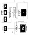
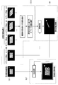
- FIG. 1 shows a block diagram of an ultrasonic diagnostic apparatus 1 according to this embodiment.
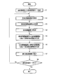
- FIG. 2 is a flowchart showing a flow of processing (puncture support processing) according to the present puncture support function.
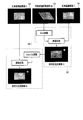
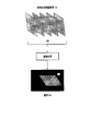
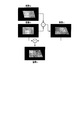
- FIG. 3 is a diagram conceptually showing the processing of steps S2 to S7 in FIG.
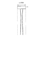
- FIG. 4 is a diagram showing an example of the beam width in the lens direction when a one-dimensional array probe is used.
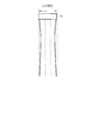
- FIG. 5 is a diagram showing an example of the beam width in the lens direction when a two-dimensional array probe is used.
- FIG. 6 is a diagram for explaining the process of step S3 according to the second modification.
- FIG. 7 is a diagram for explaining the process of step S4 according to the second modification.
- FIG. 1 shows a block diagram of an ultrasonic diagnostic apparatus 1 according to this embodiment.
- FIG. 2 is a flowchart showing a flow of processing (puncture support processing) according to the present puncture support function.
- FIG. 3 is a diagram conceptually showing
- FIG. 8 is a diagram for explaining the process of step S3 according to the third modification.
- FIG. 9 is a diagram for explaining the process of step S4 according to the fourth modification.
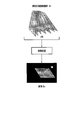
- FIG. 10 is a diagram for explaining the effect of the ultrasonic diagnostic apparatus according to the present embodiment.
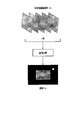
- FIG. 11 is a diagram conceptually illustrating a puncture support process according to the second embodiment.
- FIG. 12 is a diagram conceptually illustrating a puncture support process according to Modification 1 of the second embodiment.
- FIG. 13 is a diagram conceptually illustrating a puncture support process according to Modification 2 of the second embodiment.
- FIG. 14 is a diagram for explaining processing in a conventional ultrasonic diagnostic apparatus.
- FIG. 1 is a block diagram of an ultrasonic diagnostic apparatus 1 according to this embodiment.
- the ultrasonic diagnostic apparatus 1 includes an ultrasonic probe 12, an input device 13, a monitor 14, an ultrasonic transmission unit 21, an ultrasonic reception unit 22, a B-mode processing unit 23, a Doppler processing unit 24, A RAW data memory 25, a volume data generation unit 26, an image processing unit 28, a display processing unit 30, a control processor (CPU) 31, a puncture support image generation unit 32, a storage unit 33, and an interface unit 35 are provided.
- CPU control processor
- the ultrasonic probe 12 is a device (probe) that transmits ultrasonic waves to a subject and receives reflected waves from the subject based on the transmitted ultrasonic waves, and is arranged in a plurality at the tip thereof.
- a piezoelectric vibrator, a matching layer, a backing material, and the like are included.
- the piezoelectric vibrator transmits an ultrasonic wave in a desired direction in the scan region based on a drive signal from the ultrasonic transmission unit 21, and converts a reflected wave from the subject into an electric signal.
- the matching layer is an intermediate layer provided in the piezoelectric vibrator for efficiently propagating ultrasonic energy.
- the backing material prevents ultrasonic waves from propagating backward from the piezoelectric vibrator.
- the transmitted ultrasonic waves are successively reflected by the discontinuous surface of the acoustic impedance of the body tissue and received by the ultrasonic probe 12 as an echo signal.
- the amplitude of this echo signal depends on the difference in acoustic impedance at the discontinuous surface that is to be reflected.
- the echo when the transmitted ultrasonic pulse is reflected by the moving bloodstream undergoes a frequency shift due to the Doppler effect depending on the velocity component in the ultrasonic transmission / reception direction of the moving body.
- the ultrasonic probe 12 uses a one-dimensional ultrasonic probe in which ultrasonic transducers are arranged in a predetermined direction as an example.
- the input device 13 is connected to the device main body 11, and various switches, buttons, and tracks for incorporating various instructions, conditions, region of interest (ROI) setting instructions, various image quality condition setting instructions, etc. from the operator into the device main body 11. It has a ball, mouse, keyboard, etc.
- the input device 13 has a dedicated switch for inputting a diagnostic region, a dedicated knob for controlling the range of color data used for imaging, and the transparency (opacity of voxels) in the near-luminal blood flow rendering function described later. ) Has special knobs for controlling.
- the monitor 14 displays in-vivo morphological information and blood flow information as an image based on the video signal from the display processing unit 30.
- the ultrasonic transmission unit 21 has a trigger generation circuit, a delay circuit, a pulsar circuit, and the like (not shown).
- a trigger pulse for forming a transmission ultrasonic wave is repeatedly generated at a predetermined rate frequency fr Hz (cycle: 1 / fr second).
- a delay time required for focusing the ultrasonic wave into a beam shape for each channel and determining the transmission directivity is given to each trigger pulse.
- the pulsar circuit applies a drive pulse to the probe 12 at a timing based on the trigger pulse.
- the ultrasonic receiving unit 22 has an amplifier circuit, an A / D converter, a delay circuit, an adder and the like not shown.
- the amplifier circuit amplifies the echo signal captured via the probe 12 for each channel.
- the A / D converter converts the amplified analog echo signal into a digital echo signal.
- the delay circuit determines the reception directivity for the digitally converted echo signal, gives a delay time necessary for performing the reception dynamic focus, and then performs an addition process in the adder. By this addition, the reflection component from the direction corresponding to the reception directivity of the echo signal is emphasized, and a comprehensive beam for ultrasonic transmission / reception is formed by the reception directivity and the transmission directivity.
- the B-mode processing unit 23 receives the echo signal from the receiving unit 22, performs logarithmic amplification, envelope detection processing, and the like, and generates data in which the signal intensity is expressed by brightness.
- the Doppler processing unit 24 extracts a blood flow signal from the echo signal received from the reception unit 22 and generates blood flow data. Extraction of blood flow is usually performed by CFM (Color Flow Mapping). In this case, the blood flow signal is analyzed, and blood flow information such as average velocity, dispersion, power, etc. is obtained for multiple points as blood flow data.
- CFM Color Flow Mapping
- the RAW data memory 25 generates B-mode RAW data, which is B-mode data on a three-dimensional ultrasonic scanning line, using a plurality of B-mode data received from the B-mode processing unit 23.
- the RAW data memory 25 generates blood flow RAW data, which is blood flow data on a three-dimensional ultrasonic scanning line, using a plurality of blood flow data received from the Doppler processing unit 24.
- a spatial smoothing may be performed by inserting a three-dimensional filter after the RAW data memory 25.
- the volume data generation unit 26 generates B-mode volume data blood flow volume data from the B-mode RAW data received from the RAW data memory 25 by executing RAW-voxel conversion.
- the image processing unit 28 is a predetermined image such as volume rendering, multi-section conversion display (MPR: multi-planar reconstruction), maximum value projection display (MIP: maximum-intensity-projection). Process.
- MPR multi-section conversion display
- MIP maximum value projection display
- a two-dimensional filter may be inserted after the image processing unit 28 to perform spatial smoothing.
- the display processing unit 30 executes various processes such as dynamic range, brightness (brightness), contrast, ⁇ curve correction, and RGB conversion on various image data generated and processed in the image processing unit 28.
- the control processor 31 has a function as an information processing apparatus (computer) and controls the operation of the main body of the ultrasonic diagnostic apparatus.
- the control processor 31 reads out a dedicated program for realizing a puncture support support function, which will be described later, from the storage unit 33, develops it on its own memory, and executes arithmetic / control related to various processes.
- the puncture support image generation unit 32 generates an image for supporting puncture based on a puncture support output function described later.
- the storage unit 33 is a dedicated program for realizing a puncture support support function described later, a diagnostic information (patient ID, doctor's findings, etc.), a diagnostic protocol, transmission / reception conditions, a program for realizing a speckle removal function, A body mark generation program, a conversion table for presetting the range of color data used for imaging for each diagnostic part, and other data groups are stored. Further, it is also used for storing images in an image memory (not shown) as required. Data in the storage unit 33 can also be transferred to an external peripheral device via the interface unit 35.
- the interface unit 35 is an interface related to the input device 13, the network, and a new external storage device (not shown). Data such as ultrasonic images and analysis results obtained by the apparatus can be transferred by the interface unit 32 to another apparatus via a network.
- Puncture support function Next, the puncture support function that the ultrasonic diagnostic apparatus 1 has will be described.
- this function sets an area to be scanned by ultrasound so as not to be detached from the puncture needle, and the living tissue and the puncture needle And generate and provide a puncture support image that is always well imaged.
- FIG. 2 is a flowchart showing a flow of processing according to the present puncture support function (puncture support processing).
- Puncture support processing the content of the process performed in each step shown in the flowchart will be described.
- Step S1 Input of patient information and selection of puncture support mode Input of patient information, examination information and the like through the operation unit 33 and selection of a puncture support mode in which the present puncture support function is executed are executed (step S1). Various information inputted and selected is automatically stored in the storage device 29. In addition, the control unit 31 activates a program for executing the puncture support function in response to the selection operation of the puncture support mode.
- Step S2 ultrasonic transmission / reception is performed by an imaging method or transmission / reception setting in which the biological tissue is well depicted, such as tissue harmonic imaging, and a biological high-definition image A in which the biological tissue is visualized with high definition is acquired ( Step S2).
- the biological high-definition image A is not limited to an image captured by tissue harmonic imaging, and may be an image captured using a received signal including a fundamental wave component in the frequency band.
- an ultrasonic image over a plurality of frames may be an image captured by tissue harmonic imaging, or an image captured with the fundamental wave component included in the frequency band.
- a pulse subtraction method (a technique for obtaining a reception data in a harmonic band by adding a plurality of pulses having different polarities or phases) may be used.
- the number of added pulses is not particularly limited, and an arbitrary number of pulses may be used.
- the pulse subtraction method may be executed to acquire ultrasonic data over a plurality of frames (a plurality of volumes), and an addition process and a difference process using these may be executed to generate the biological high-definition image A. .
- a puncture needle emphasized image B is acquired by executing an oblique scan in which the direction is substantially perpendicular to the longitudinal direction of the needle (step S3).
- the transmission / reception setting is not limited to the above contents, and for example, using at least one of the element pitch of the ultrasonic transducer of the ultrasonic probe 12 to be used, the transmission / reception frequency characteristics of the ultrasonic transducer, the oblique angle, and the like. Transmission / reception conditions can be controlled. In particular, it is theoretically known that the following equation should be satisfied in order to prevent the appearance of grating lobes.
- step S3 the control processor 31 sets the wavelength (or frequency) of the transmission waveform, the reception center frequency, and the reception frequency band either automatically or by manual input from the input device 13 so as to satisfy the conditional expression (1).
- the control processor 31 sets the wavelength (or frequency) of the transmission waveform, the reception center frequency, and the reception frequency band either automatically or by manual input from the input device 13 so as to satisfy the conditional expression (1).
- the conditional expression (1) there is no transmission / reception condition that satisfies the conditional expression (1). In such a case, it is preferable to select a condition in which a grating lobe does not enter the image as much as possible based on the conditional expression (1).
- the oblique angle is preferably set so that the ultrasonic beam is transmitted to the puncture needle at an angle that is perpendicular or nearly perpendicular.
- the guide line of the puncture needle can be displayed on the ultrasonic image by registering the angle of the puncture needle with respect to the adapter in the ultrasonic diagnostic apparatus.
- the control processor 31 automatically determines the oblique angle based on the registered angle of the puncture needle.
- the control processor 31 automatically determines the oblique angle based on the position detected by the position sensor.
- the oblique angle may be automatically determined based on the direction of the puncture needle. Furthermore, the oblique angle may be set and adjusted by manual input from the input device 13 with reference to the direction of the puncture needle on the ultrasonic image.
- Step S4 the main lobe scanning angle is set to 0, and transmission / reception conditions other than the scanning angle are substantially the same as the conditions when the puncture needle emphasized image B is acquired (that is, the transmission / reception conditions set in step S3).
- a sound wave transmission / reception is executed to create a biological tissue image C (step S4).
- step S3 and step S4 can be switched as necessary.
- the ultrasonic scanning area in step S3 and the ultrasonic scanning area in step S4 do not have to be the same. That is, in step S3, an ultrasonic scanning region may be set so as to meet the purpose of emphasizing and visualizing the puncture needle, while in step S4, it is included in the puncture needle emphasized image B.
- the ultrasonic scanning region may be set so as to meet the purpose of canceling the tissue (for example, including at least the tissue region included in the puncture needle emphasized image B).
- the puncture support image generation unit 32 generates a puncture needle extraction image D by image processing using the puncture needle emphasized image B and the biological tissue image C (step S5). For example, the puncture support image generation unit 32 compares the luminance value of the puncture needle emphasized image B and the luminance value of the biological tissue image C for each spatially corresponding position, and the luminance value of the biological tissue image C is large. Is assigned 0, and when the luminance value of the puncture needle emphasized image B is large, the luminance value of the image B is assigned to each position, thereby generating the puncture needle extraction image D.
- the luminance value of the puncture needle included in the puncture needle emphasis image B is assigned to the position corresponding to the puncture needle on the puncture needle extraction image D, while the area other than the puncture needle on the puncture needle extraction image D is assigned. Is assigned a luminance value of 0. Therefore, the puncture needle extraction image D is a good image obtained by extracting the puncture needle.
- the method of generating the puncture needle extraction image D is not limited to the comparison of luminance values as described above.
- the luminance value of the puncture needle emphasized image B and the luminance value of the biological tissue image C are averaged at each spatially corresponding position, or an addition / subtraction process (addition process, difference process) or the like is performed. May be assigned as the luminance value at each position to generate the puncture needle extraction image D.
- the gain and the dynamic range are set for at least one of the puncture needle emphasized image B and the biological tissue image C so that the puncture needle or the biological tissue is emphasized (or suppressed). You may make it adjust at least one of these.
- the difference in acoustic impedance is very large between a curable substance such as a puncture needle and a living tissue. For this reason, the reflection signal from the puncture needle is very large compared to the reflection signal of the biological tissue, and the puncture needle is displayed with higher luminance in the puncture needle emphasized image B than the surrounding biological tissue.
- the puncture needle emphasized image B by lowering the gain of the puncture needle emphasized image B relative to the biological tissue image C, or so that the tissue of the puncture needle emphasized image B and the tissue of the biological tissue image C have the same brightness.
- the gain By correcting the gain, the luminance at the position corresponding to the living tissue can be reduced to 0 when the puncture needle extraction image D is generated.
- the puncture needle corresponding to the high luminance region can be extracted effectively.
- the puncture support image generation unit 32 uses the puncture needle extraction image D in which the puncture needle is well imaged and the living body high-definition image A in which the living tissue is imaged in high definition, to perform the puncture support.
- An image E is generated (step S6).
- the puncture support image generation unit 32 determines the brightness value of the living body high-definition image A in which only the living body is imaged in high definition and the brightness value of the puncture needle extraction image D from which the puncture needle is extracted.
- the puncture support image E is an image in which a high-luminance needle image is displayed on the living body high-definition image A with good image quality. Further, by performing at least one of addition processing, difference processing, maximum value projection processing, minimum value projection processing, and averaging processing using the puncture needle extraction image D and the living body high-definition image A, puncture The support image E may be generated.
- the generation method of the puncture support image E is not limited to the comparison of luminance values as described above.
- the luminance value of the puncture needle extraction image D and the luminance value of the biological high-definition image A are averaged at each spatially corresponding position, addition / subtraction processing, etc. are executed, and the obtained value is used as the luminance value at each position
- the puncture support image E may be generated.
- at least one of the gain and the dynamic range may be adjusted for at least one of the puncture needle extraction image D and the living body high-definition image A.
- the puncture needle extraction image D is a display of only high-luminance needles.
- the signal from the tissue region can be suppressed or eliminated by narrowing the dynamic range of the puncture needle extraction image D, and the region corresponding to the puncture needle can be illuminated with high luminance by increasing the gain.
- the gain and dynamic range are adjusted by generating a histogram relating to the luminance of the puncture needle extraction image D, and automatically by threshold processing using the generated histogram or manually by manual operation from the input device 13. Can be executed.
- Step S8 The above-described processing of steps S2 to S7 is repeatedly executed sequentially during puncture.
- FIG. 3 is a diagram conceptually showing the processing of steps S2 to S7 in FIG. As shown in the figure, each process corresponding to each of steps S2 to S7 is executed, and the puncture support image E is sequentially updated and displayed. The operator can easily visually recognize the relative positional relationship between the living tissue and the puncture needle by observing the puncture support image E displayed in real time.
- the ultrasonic probe 12 is a one-dimensional array probe is taken as an example.
- a 1.5-dimensional array probe or a two-dimensional array probe may be adopted as the ultrasonic probe 12. Accordingly, the beam width in the lens direction when using the two-dimensional array probe (see FIG. 5) is compared with the beam width in the lens direction (slice direction) when using the one-dimensional array probe (see FIG. 4).
- the puncture needle emphasized image group Bn and the biological tissue image C can be captured. As a result, even when the position of the puncture needle is slightly shifted from directly below the ultrasonic probe 12, the puncture needle can always be imaged appropriately.
- the beam width in the lens direction is increased in the imaging of the puncture needle emphasized image group Bn
- the beam width in the lens direction is also increased in the imaging of the biological tissue image C (the puncture needle emphasized image). It is desirable that the beam width is the same as that in imaging of the group Bn.
- step S3 When a two-dimensional array probe is used as the ultrasonic probe 12, the processes in steps S3, S4, and S5 may be performed as follows. That is, in the process of step S3, as shown in FIG. 6, the puncture needle emphasized image group Bn is acquired by n oblique scans parallel to the slice direction, and the luminance value is averaged for each spatially corresponding position. Alternatively, addition / subtraction processing or the like is executed to generate the image Ba. Further, in the process of step S4, as shown in FIG. 7, the biological tissue image group Cn is acquired by the normal scan obtained by the n normal scans parallel to the slice direction, and the luminance value is obtained at each spatially corresponding position. The averaging process or the addition / subtraction process is executed to generate the image Ca. The puncture needle extraction image D may be generated by performing the above-described brightness value comparison processing in step S5 using the image Ba and the image Ca thus obtained.
- the puncture needle is adjusted by the weight of the average probe or the addition process according to the distance from the position immediately below the ultrasonic probe 12 of each image. It is possible to visually recognize how far it is from directly below. For example, when the puncture needle is away from just below the ultrasound probe 12 by reducing the weighting as it moves away from directly below the ultrasound probe 12, the puncture needle of the puncture support image E has low (dark) luminance. On the other hand, when the puncture needle is present directly below the ultrasonic probe 12, the puncture needle of the puncture support image E is displayed with high (bright) luminance. The surgeon can easily grasp the positional relationship between the ultrasonic probe 12 (and the scanning region) and the puncture needle based on the luminance of the puncture needle displayed in the puncture support image E.
- step S3 When a mechanical four-dimensional probe (probe capable of scanning a three-dimensional region over time by oscillating a one-dimensional transducer array) is used as the ultrasonic probe 12, steps S3 and S4 are performed as in the second modification. , S5 may be performed as follows. That is, in the process of step S3, as shown in FIG. 8, the puncture corresponding to n scanning sections is performed by executing an oblique scan while moving (swinging) the scanning section along the slice direction. The needle-enhanced image group Bn is acquired, and the luminance value averaging process or addition / subtraction process is executed for each spatially corresponding position to generate the image Ba. Further, in the process of step S4, as shown in FIG.
- the normal scan is executed while moving (swinging) the scan section so as to sway along the slice direction, thereby corresponding to n scan sections.
- the biological tissue image group Cn is acquired, and luminance value averaging processing or addition / subtraction processing is executed for each spatially corresponding position to generate an image Ca.
- the puncture needle extraction image D may be generated by performing the above-described brightness value comparison processing in step S5 using the image Ba and the image Ca thus obtained. Of course, it is possible to perform the same weighting process as in the second modification.
- the ultrasonic diagnostic apparatus when performing a puncture operation while monitoring a living tissue and a puncture needle, as shown in FIG. 10, using a scanned region set so as not to be removed from the puncture needle.
- a puncture needle-enhanced image is acquired by an oblique scan
- a biological tissue image is acquired by a normal scan that differs only in the transmission / reception direction from the puncture needle-enhanced image.
- Generated Since the puncture needle-emphasized image and the biological tissue image are acquired under substantially the same transmission / reception conditions except for the transmission / reception direction, the puncture needle from which the biological tissue is suitably removed and the puncture needle is extracted using both An extracted image can be generated.
- a puncture support image including a high-definition image of a biological tissue and a puncture needle suitably extracted using the puncture needle extraction image thus obtained and a biological high-definition image obtained by tissue harmonic imaging or the like Is generated and displayed.
- the ultrasonic diagnostic apparatus 1 acquires a puncture needle emphasized image B (or a puncture needle emphasized image group Bn.
- the puncture needle emphasized image B is taken as an example) corresponding to each of a plurality of oblique angles. Then, based on the angle of the puncture needle inserted into the subject, the puncture needle-enhanced image B corresponding to the oblique angle optimum for imaging the puncture needle is selected, and the puncture needle extraction image D is generated using this image. Is.
- step S3 and step S5 when the puncture support process according to the present embodiment is compared with the puncture support process according to the first embodiment, the processes in steps S3 and S5 in FIG. 2 are different.
- step S3 and step S5 according to the present embodiment will be mainly described.
- FIG. 11 is a diagram conceptually showing a puncture support process according to the second embodiment (the step numbers in FIG. 11 correspond to the step numbers shown in FIG. 2).
- the corresponding puncture needle emphasized image B of each of the plurality of oblique angles is acquired.
- the transmission / reception setting at each oblique angle is the same as that in the first embodiment.
- the control processor 31 detects the insertion angle ⁇ of the puncture needle with respect to the subject.
- the detection of the insertion angle ⁇ of the puncture needle can be realized, for example, by performing a line segment detection process using at least one of the plurality of puncture needle emphasized images B.
- the insertion angle may be detected by a detector provided in the puncture needle adapter.
- the control processor 31 uses the puncture needle emphasized image D used to generate the puncture needle emphasized image D from the plurality of puncture needle emphasized images B corresponding to the plurality of oblique angles based on the detected puncture angle ⁇ of the puncture needle. Select B.
- step S5 the puncture support image generation unit 32 generates a puncture needle extraction image D by image processing using the selected puncture needle emphasis image B and biological tissue image C.
- the specific contents of the image processing are the same as in the first embodiment.
- control processor 31 controls at least one of the plurality of oblique angles and the number of oblique angles (the number of oblique directions) in accordance with the angle of the puncture needle detected in step S3 and its change over time. .
- the transmission / reception conditions are determined and controlled according to the determined plurality of oblique angles and the number of oblique angles.
- the angle of the puncture needle inserted into the subject varies from surgery to surgery.
- the puncture needle emphasized image B corresponding to each of the plurality of oblique angles is acquired, and the puncture needle is visualized based on the angle of the puncture needle inserted into the subject.
- a puncture needle emphasis image B corresponding to the optimum oblique angle is selected, and a puncture needle extraction image D and a puncture support image E can be generated using this. Therefore, in the puncture operation, the puncture needle can always be suitably imaged, which can contribute to improvement of the safety and quality of the puncture operation.
- the puncture needle emphasized image B corresponding to the optimum oblique angle is selected from the plurality of oblique images.
- the maximum value projection image of the plurality of oblique images is selected as the puncture needle. It may be used as the enhanced image B. If the accuracy of the puncture angle detection is low, it is assumed that an optimal puncture needle emphasis image cannot be selected. Therefore, an image in which the puncture needle is always emphasized can be obtained by performing maximum value projection without detection. It becomes possible to create.
- the processing is not limited to the maximum value and the projection, and may be average, addition, or the like.
- the puncture support function according to each of the embodiments can also be realized by installing a program for executing the processing in a computer such as a workstation and developing these on a memory.
- a program capable of causing the computer to execute the method is stored in a recording medium such as a magnetic disk (floppy (registered trademark) disk, hard disk, etc.), an optical disk (CD-ROM, DVD, etc.), or a semiconductor memory. It can also be distributed.
- the puncture support process is executed using the luminance value after image reconstruction.
- puncture support processing may be executed using RAW data before image reconstruction.
- an ultrasonic diagnostic apparatus and an ultrasonic diagnostic apparatus control method capable of monitoring a living tissue and a puncture needle with good and high-quality images when performing a puncture.
Abstract
【課題】 生体組織及び穿刺針を良好且つ高画質な画像を提供すること。 【解決手段】 穿刺術において被検体内の穿刺針の位置及び刺入方向を観察するために利用される超音波診断装置であって、被検体内について第1の送受信設定で第1の超音波スキャンを実行することで複数の第1の超音波データを取得し、被検体内について第2の送受信設定で第2の超音波スキャンを実行することで複数の第2の超音波データを取得し、第3の送受信設定で第3の超音波スキャンを実行することで複数の第3の超音波データを取得するデータ取得ユニットと、第1の超音波データを用いて生体組織が表示されている組織画像を生成し、第2の超音波データと第3の超音波データとを用いた画像処理に基づき穿刺針が表示されている穿刺画像を生成し、組織画像と穿刺画像とを用いて、生体組織と穿刺針とが映像化された合成画像を生成する画像生成ユニットと、を具備する。
Description
特に超音波ガイド下穿刺において、生体の画質を落とさずに針の視認性を向上させるための超音波診断装置及び超音波診断装置制御方法に関する。
超音波診断は、超音波プローブを体表から当てるだけの簡単な操作で心臓の拍動や胎児の動きの様子がリアルタイム表示で得られ、かつ安全性が高いため繰り返して検査が行えるほか、システムの規模がX線、CT、MRIなど他の診断機器に比べて小さく、ベッドサイドへ移動していっての検査も容易に行えるなど簡便である。また、超音波診断はX線などのように被曝の影響がなく、産科や在宅医療等においても使用することができる。
また、超音波診断装置は、画像診断のみばかりでなく、例えば肝細胞癌の局所治療法としてラジオ波焼灼療法(RFA)や肝細胞組織を検査する生検等においても用いられる。これらの治療、検査においては、穿刺針を用いて、腫瘍などの関心部位に正確に穿刺が行われるため、超音波診断装置を用いて、関心領域及び穿刺針がリアルタイムでモニタリングされる。
しかしながら、従来の超音波診断装置を穿刺術のモニタリングに利用する場合、以下の点において十分ではない。
まず、従来の超音波診断装置によって提供される通常の超音波画像を用いてモニタリングしながら穿刺術を行う場合、病変の位置や針の侵入角度の影響で針が見えにくくなることがある。係る場合、針を動かした際の組織の動きなどを見ながら穿刺針の位置等を間接的に把握するといった具合に、医師の経験や知識に頼るところが大きいのが実情である。
また、例えば図14に示す様に、オブリークスキャン(超音波ビームが針に垂直に当たるようにビーム角度を調整したスキャン)によって得られた画像Aと、(オブリークスキャンを行わない)通常の超音波スキャンによって得られた画像Bとを用い、画像Bから画像Aを差分することで針を抽出した画像Cを作成し、画像Aと画像Cを加算した画像を用いて、穿刺術における超音波画像モニタリングを行うという技術がある(特許文献1参照)。しかしながら、当該技術を用いる場合でも、上記オブリークスキャンを実行した場合、ビーム形状などの問題からグレーティングローブが発生し、その結果画像内にアーチファクトが発生してしまうことがある。また、超音波ビームが針に垂直に当たるようにオブリークスキャンを行っても、針の位置がスキャン断面から少しでも外れていると、結局針を好適に映像化することができない場合がある。
上記事情を鑑みてなされたもので、穿刺術を行う場合において、生体組織及び穿刺針を良好且つ高画質な画像にてモニタリング可能な超音波診断装置及び超音波診断装置制御方法を提供することを目的としている。
一実施形態に係る超音波診断装置は、穿刺術において被検体内の穿刺針の位置及び刺入方向を観察するために利用される超音波診断装置であって、前記被検体内について第1の送受信設定で第1の超音波スキャンを実行することで複数の第1の超音波データを取得し、前記被検体内について第2の送受信設定で第2の超音波スキャンを実行することで複数の第2の超音波データを取得し、第3の送受信設定で第3の超音波スキャンを実行することで複数の第3の超音波データを取得するデータ取得ユニットと、前記第1の超音波データを用いて生体組織が表示されている組織画像を生成し、前記第2の超音波データと前記第3の超音波データとを用いた画像処理に基づき前記穿刺針が表示されている穿刺画像を生成し、前記組織画像と前記穿刺画像とを用いて、前記生体組織と前記穿刺針とが映像化された合成画像を生成する画像生成ユニットと、前記合成画像を表示する表示ユニットと、を具備するものである。
一実施形態に係る超音波診断装置制御方法は、穿刺術において被検体内の穿刺針の位置及び刺入方向を観察するために利用される超音波診断装置を制御する方法であって、前記被検体内について第1の送受信設定で第1の超音波スキャンを実行して複数の第1の超音波データを取得し、前記被検体内について第2の送受信設定で第2の超音波スキャンを実行することで複数の第2の超音波データを取得し、第3の送受信設定で第3の超音波スキャンを実行することで複数の第3の超音波データを取得させるデータ取得し、前記第1の超音波データを用いて生体組織が表示されている組織画像を生成し、前記第2の超音波データと前記第3の超音波データとを用いて前記穿刺針が表示されている穿刺画像を生成し、前記組織画像と前記穿刺画像とを用いて、前記生体組織と前記穿刺針とが映像化された合成画像を生成し、前記合成画像を表示すること、を具備するものである。
以上述べた構成によれば、穿刺術を行う場合において、生体組織及び穿刺針を良好且つ高画質な画像にてモニタリング可能な超音波診断装置及び超音波診断装置制御方法を実現することができる。
以下、実施形態を図面に従って説明する。なお、以下の説明において、略同一の機能及び構成を有する構成要素については、同一符号を付し、重複説明は必要な場合にのみ行う。
図1は、本実施形態に係る超音波診断装置1のブロック構成図を示している。同図に示すように、本超音波診断装置1は、超音波プローブ12、入力装置13、モニター14、超音波送信ユニット21、超音波受信ユニット22、Bモード処理ユニット23、ドプラ処理ユニット24、RAWデータメモリ25、ボリュームデータ生成ユニット26、画像処理ユニット28、表示処理ユニット30、制御プロセッサ(CPU)31、穿刺術支援画像生成ユニット32、記憶ユニット33、インタフェースユニット35を具備している。以下、個々の構成要素の機能について説明する。
超音波プローブ12は、被検体に対して超音波を送信し、当該送信した超音波に基づく被検体からの反射波を受信するデバイス(探触子)であり、その先端に複数に配列された圧電振動子、整合層、バッキング材等を有している。圧電振動子は、超音波送信ユニット21からの駆動信号に基づきスキャン領域内の所望の方向に超音波を送信し、当該被検体からの反射波を電気信号に変換する。整合層は、当該圧電振動子に設けられ、超音波エネルギーを効率良く伝播させるための中間層である。バッキング材は、当該圧電振動子から後方への超音波の伝播を防止する。当該超音波プローブ12から被検体Pに超音波が送信されると、当該送信超音波は、体内組織の音響インピーダンスの不連続面で次々と反射され、エコー信号として超音波プローブ12に受信される。このエコー信号の振幅は、反射することになった不連続面における音響インピーダンスの差に依存する。また、送信された超音波パルスが、移動している血流で反射された場合のエコーは、ドプラ効果により移動体の超音波送受信方向の速度成分に依存して、周波数偏移を受ける。なお、本実施形態に係る超音波プローブ12は、超音波振動子が所定の方向に沿って配列された一次元超音波プローブを用いる場合を例とする。
入力装置13は、装置本体11に接続され、オペレータからの各種指示、条件、関心領域(ROI)の設定指示、種々の画質条件設定指示等を装置本体11にとりこむための各種スイッチ、ボタン、トラックボール、マウス、キーボード等を有している。また、入力装置13は、後述する管腔近傍血流描出機能において、診断部位を入力するための専用スイッチ、映像化に用いるカラーデータの範囲を制御するための専用ツマミ、ボクセルの透明度(不透明度)を制御するための専用ツマミ等を有している。
モニター14は、表示処理ユニット30からのビデオ信号に基づいて、生体内の形態学的情報や、血流情報を画像として表示する。
超音波送信ユニット21は、図示しないトリガ発生回路、遅延回路およびパルサ回路等を有している。トリガ発生回路では、所定のレート周波数fr Hz(周期;1/fr秒)で、送信超音波を形成するためのトリガパルスが繰り返し発生される。また、遅延回路では、チャンネル毎に超音波をビーム状に集束し且つ送信指向性を決定するのに必要な遅延時間が、各トリガパルスに与えられる。パルサ回路は、このトリガパルスに基づくタイミングで、プローブ12に駆動パルスを印加する。
超音波受信ユニット22は、図示していないアンプ回路、A/D変換器、遅延回路、加算器等を有している。アンプ回路では、プローブ12を介して取り込まれたエコー信号をチャンネル毎に増幅する。A/D変換器では、増幅されたアナログのエコー信号をデジタルエコー信号に変換する。遅延回路では、デジタル変換されたたエコー信号に対し受信指向性を決定し、受信ダイナミックフォーカスを行うのに必要な遅延時間を与え、その後加算器において加算処理を行う。この加算により、エコー信号の受信指向性に応じた方向からの反射成分が強調され、受信指向性と送信指向性とにより超音波送受信の総合的なビームが形成される。
Bモード処理ユニット23は、受信ユニット22からエコー信号を受け取り、対数増幅、包絡線検波処理などを施し、信号強度が輝度の明るさで表現されるデータを生成する。
ドプラ処理ユニット24は、受信ユニット22から受け取ったエコー信号から血流信号を抽出し、血流データを生成する。血流の抽出は、通常CFM(Color Flow Mapping)で行われる。この場合、血流信号を解析し、血流データとして平均速度、分散、パワー等の血流情報を多点について求める。
RAWデータメモリ25は、Bモード処理ユニット23から受け取った複数のBモードデータを用いて、三次元的な超音波走査線上のBモードデータであるBモードRAWデータを生成する。また、RAWデータメモリ25は、ドプラ処理ユニット24から受け取った複数の血流データを用いて、三次元的な超音波走査線上の血流データである血流RAWデータを生成する。なお、ノイズ低減や画像の繋がりを良くすることを目的として、RAWデータメモリ25の後に三次元的なフィルタを挿入し、空間的なスムージングを行うようにしてもよい。
ボリュームデータ生成ユニット26は、RAW-ボクセル変換を実行することにより、RAWデータメモリ25から受け取ったBモードRAWデータから、Bモードボリュームデータ血流ボリュームデータを生成する。
画像処理ユニット28は、ボリュームデータ生成ユニット26から受け取るボリュームデータに対して、ボリュームレンダリング、多断面変換表示(MPR:multi planar reconstruction)、最大値投影表示(MIP:maximum intensity projection)等の所定の画像処理を行う。なお、ノイズ低減や画像の繋がりを良くすることを目的として、画像処理ユニット28の後に二次元的なフィルタを挿入し、空間的なスムージングを行うようにしてもよい。
表示処理ユニット30は、画像処理ユニット28において生成・処理された各種画像データに対し、ダイナミックレンジ、輝度(ブライトネス)、コントラスト、γカーブ補正、RGB変換等の各種を実行する。
制御プロセッサ31は、情報処理装置(計算機)としての機能を持ち、本超音波診断装置本体の動作を制御する。制御プロセッサ31は、記憶ユニット33から後述する穿刺術支援出機能を実現するための専用プログラムを読み出して自身が有するメモリ上に展開し、各種処理に関する演算・制御等を実行する。
穿刺術支援画像生成ユニット32は、後述する穿刺術支援出機能に基づいて、穿刺術を支援するための画像を生成する。
記憶ユニット33は、後述する穿刺術支援出機能を実現するための専用プログラムや、診断情報(患者ID、医師の所見等)、診断プロトコル、送受信条件、スペックル除去機能を実現するためのプログラム、ボディマーク生成プログラム、映像化に用いるカラーデータの範囲を診断部位毎に予め設定する変換テーブル、その他のデータ群が保管されている。また、必要に応じて、図示しない画像メモリ中の画像の保管などにも使用される。記憶ユニット33のデータは、インタフェースユニット35を経由して外部周辺装置へ転送することも可能となっている。
インタフェースユニット35は、入力装置13、ネットワーク、新たな外部記憶装置(図示せず)に関するインタフェースである。当該装置によって得られた超音波画像等のデータや解析結果等は、インタフェースユニット32よって、ネットワークを介して他の装置に転送可能である。
(穿刺術支援機能)
次に、本超音波診断装置1が有する穿刺術支援機能について説明する。この機能は、超音波診断装置を用いて生体組織及び穿刺針をモニタリングしながら穿刺術を行う場合において、穿刺針から外れないように超音波による被走査領域を設定しつつ、生体組織と穿刺針とが常に良好に映像化された穿刺術支援画像を生成し提供するものである。
次に、本超音波診断装置1が有する穿刺術支援機能について説明する。この機能は、超音波診断装置を用いて生体組織及び穿刺針をモニタリングしながら穿刺術を行う場合において、穿刺針から外れないように超音波による被走査領域を設定しつつ、生体組織と穿刺針とが常に良好に映像化された穿刺術支援画像を生成し提供するものである。
図2は、本穿刺術支援機能に従う処理(穿刺術支援処理)の流れを示したフローチャートである。以下、当該フローチャートに示す各ステップにおいて実行される処理の内容について説明する。
[患者情報等の入力、穿刺術支援モードの選択:ステップS1]
操作ユニット33を介して患者情報、検査情報等の入力、本穿刺術支援機能が実行される穿刺術支援モードの選択が実行される(ステップS1)。入力、選択された各種情報は、自動的に記憶装置29に記憶される。また、制御ユニット31は、穿刺術支援モードの選択操作に応答して、穿刺術支援機能を実行するためのプログラムを起動させる。
操作ユニット33を介して患者情報、検査情報等の入力、本穿刺術支援機能が実行される穿刺術支援モードの選択が実行される(ステップS1)。入力、選択された各種情報は、自動的に記憶装置29に記憶される。また、制御ユニット31は、穿刺術支援モードの選択操作に応答して、穿刺術支援機能を実行するためのプログラムを起動させる。
[生体高精細画像Aの取得:ステップS2]
次に、組織ハーモニックイメージング等、生体組織が良好に描出されるイメージング法或いは送受信設定にて超音波送受信が実行され、生体組織が高精細に映像化された生体高精細画像Aが取得される(ステップS2)。なお、生体高精細画像Aは組織ハーモニックイメージングにより撮像された画像に限られず、基本波成分を周波数帯域に含む受信信号を用いて撮像された画像であっても構わない。更に、必要に応じて、複数フレーム(複数ボリューム)に亘る超音波データを用いた加算処理、差分処理、最大値投影処理、最小値投影処理、平均化処理のうちの少なくともいずれかを実行し、生体高精細画像Aを生成するようにしてもよい。この複数フレーム(複数ボリューム)に亘る超音波画像も同様に、組織ハーモニックイメージングにより撮像された画像を用いても、基本波成分を周波数帯域に含めて撮像された画像を用いても構わない。
次に、組織ハーモニックイメージング等、生体組織が良好に描出されるイメージング法或いは送受信設定にて超音波送受信が実行され、生体組織が高精細に映像化された生体高精細画像Aが取得される(ステップS2)。なお、生体高精細画像Aは組織ハーモニックイメージングにより撮像された画像に限られず、基本波成分を周波数帯域に含む受信信号を用いて撮像された画像であっても構わない。更に、必要に応じて、複数フレーム(複数ボリューム)に亘る超音波データを用いた加算処理、差分処理、最大値投影処理、最小値投影処理、平均化処理のうちの少なくともいずれかを実行し、生体高精細画像Aを生成するようにしてもよい。この複数フレーム(複数ボリューム)に亘る超音波画像も同様に、組織ハーモニックイメージングにより撮像された画像を用いても、基本波成分を周波数帯域に含めて撮像された画像を用いても構わない。
また、組織ハーモニックイメージングの撮像手法として、パルスサブトラクション法(極性あるいは位相の異なるパルスを複数加算して高調波帯域の受信データを得る手法)を用いても構わない。この場合のパルス加算数に特に限定はなく、任意のパルス数を用いてよい。
さらに、パルスサブトラクション法を実行して複数フレーム(複数ボリューム)に亘る超音波データを取得し、これらを用いた加算処理、差分処理を実行し、生体高精細画像Aを生成するようにしてもよい。
[穿刺針強調画像Bを取得:ステップS3]
次に、比較的低い周波数の送信波形を用い、映像化には受信信号のうち送信波形の周波数の基本波成分を用いるなど、可能な限り送信時及び受信時のグレーティングローブが抑制され、かつ送受信方向を実質的に針の長手方向の垂直方向とするオブリークスキャンを実行することによって、穿刺針強調画像Bを取得する(ステップS3)。
次に、比較的低い周波数の送信波形を用い、映像化には受信信号のうち送信波形の周波数の基本波成分を用いるなど、可能な限り送信時及び受信時のグレーティングローブが抑制され、かつ送受信方向を実質的に針の長手方向の垂直方向とするオブリークスキャンを実行することによって、穿刺針強調画像Bを取得する(ステップS3)。
なお、送受信設定は上記内容に拘泥されず、例えば、使用する超音波プローブ12の超音波振動子のエレメントピッチ、超音波振動子の送受信周波数特性、オブリーク角度等のうちの少なくとも一つを用いて送受信条件を制御することができる。特に、グレーティングローブが出現しないようにするためには、以下の式を満たせばよいことが理論的に知られている。
d < λ/(1 + sinθM) (1)
ここで、d、λ、θMはそれぞれエレメントピッチ[mm]、波長[mm]、メインローブの走査角度(オブリーク角度、方位角度)[rad.]である。本ステップS3では、条件式(1)を満たすように、制御プロセッサ31が自動的に或いは入力装置13からのマニュアル入力によって送信波形の波長(または周波数)および受信中心周波数、受信周波数帯域を設定するようにする。しかしながら、場合によっては、条件式(1)を満たす送受信条件が存在しないこともある。係る場合には、条件式(1)等を基準として、可能な限り画像内にグレーティングローブが入らない条件を選択するようにすることが好ましい。
ここで、d、λ、θMはそれぞれエレメントピッチ[mm]、波長[mm]、メインローブの走査角度(オブリーク角度、方位角度)[rad.]である。本ステップS3では、条件式(1)を満たすように、制御プロセッサ31が自動的に或いは入力装置13からのマニュアル入力によって送信波形の波長(または周波数)および受信中心周波数、受信周波数帯域を設定するようにする。しかしながら、場合によっては、条件式(1)を満たす送受信条件が存在しないこともある。係る場合には、条件式(1)等を基準として、可能な限り画像内にグレーティングローブが入らない条件を選択するようにすることが好ましい。
オブリーク角度は、超音波ビームが垂直もしくは垂直に近い角度で穿刺針に送信されるように設定されることが好ましい。穿刺アダプタを用いる場合には、アダプタを基準とする穿刺針の角度を超音波診断装置に登録することで、超音波画像上に穿刺針のガイド線を表示することができる。係る場合には、制御プロセッサ31は、登録された穿刺針の角度に基づいて、オブリーク角度を自動的に決定する。位置センサによって穿刺針の位置や方向を検出する場合には、制御プロセッサ31は、当該位置センサによって検出される位置等に基づいてオブリーク角度を自動的に決定する。また、穿刺アダプタによる穿刺針角度の登録や位置センサ等を用いない場合であっても、例えば超音波画像上の穿刺針を一般的なエッジ検出手法や線分検出手法等を用いて検出し、当該穿刺針の方向を基準としてオブリーク角度を自動的に決定してもよい。さらに、超音波画像上の穿刺針の方向を基準として、入力装置13からのマニュアル入力によってオブリーク角度を設定、調整するようにしてもよい。
[生体組織画像Cを取得:ステップS4]
次に、メインローブの走査角度を0とし、走査角度以外の送受信条件は穿刺針強調画像Bを取得した際の条件(すなわち、ステップS3において設定された送受信条件)と実質的に同一とする超音波送受信を実行して、生体組織画像Cが作成される(ステップS4)。
次に、メインローブの走査角度を0とし、走査角度以外の送受信条件は穿刺針強調画像Bを取得した際の条件(すなわち、ステップS3において設定された送受信条件)と実質的に同一とする超音波送受信を実行して、生体組織画像Cが作成される(ステップS4)。
なお、ステップS3とステップS4の実行順序は、必要に応じて入れ替えることが可能である。また、ステップS3における超音波走査領域とステップS4における超音波走査領域とは、同一である必要はない。すなわち、ステップS3においては、穿刺針を強調して映像化するという目的に合致するように超音波走査領域を設定すればよく、一方、ステップS4においては、穿刺針強調画像Bに含まれている組織を相殺するという目的に合致するように(例えば、少なくとも穿刺針強調画像Bに含まれている組織領域を含むように)超音波走査領域を設定すればよい。
[画像B、画像Cを用いて穿刺針抽出画像Dを生成:ステップS5]
次に、穿刺術支援画像生成ユニット32は、穿刺針強調画像Bと生体組織画像Cとを用いた画像処理により、穿刺針抽出画像Dを生成する(ステップS5)。例えば、穿刺術支援画像生成ユニット32は、穿刺針強調画像Bの輝度値と生体組織画像Cの輝度値とを空間的に対応する位置毎で比較し、生体組織画像Cの輝度値が大きい場合は0を、穿刺針強調画像Bの輝度値が大きい場合は画像Bの輝度値を、各位置毎に割り当てることで、穿刺針抽出画像Dを生成する。これにより、穿刺針抽出画像D上の穿刺針に対応する位置には穿刺針強調画像Bに含まれる穿刺針の輝度値が割り当てられ、一方、穿刺針抽出画像D上の穿刺針以外の領域には輝度値0が割り当てられることになる。従って、穿刺針抽出画像Dは、穿刺針を抽出して良好に映像化したものとなる。
次に、穿刺術支援画像生成ユニット32は、穿刺針強調画像Bと生体組織画像Cとを用いた画像処理により、穿刺針抽出画像Dを生成する(ステップS5)。例えば、穿刺術支援画像生成ユニット32は、穿刺針強調画像Bの輝度値と生体組織画像Cの輝度値とを空間的に対応する位置毎で比較し、生体組織画像Cの輝度値が大きい場合は0を、穿刺針強調画像Bの輝度値が大きい場合は画像Bの輝度値を、各位置毎に割り当てることで、穿刺針抽出画像Dを生成する。これにより、穿刺針抽出画像D上の穿刺針に対応する位置には穿刺針強調画像Bに含まれる穿刺針の輝度値が割り当てられ、一方、穿刺針抽出画像D上の穿刺針以外の領域には輝度値0が割り当てられることになる。従って、穿刺針抽出画像Dは、穿刺針を抽出して良好に映像化したものとなる。
なお、穿刺針抽出画像Dの生成方法は、上記のような輝度値の比較に限定されない。例えば、穿刺針強調画像Bの輝度値と生体組織画像Cの輝度値とを空間的に対応する位置毎で平均化、或いは加減算処理(加算処理、差分処理)等を実行し、得られた値を各位置の輝度値として割り当てることで、穿刺針抽出画像Dを生成するようにしてもよい。
また、穿刺針抽出画像Dを生成する前処理として、例えば穿刺針或いは生体組織が強調(或いは抑制)されるように、穿刺針強調画像B及び生体組織画像Cの少なくとも一方につき、ゲイン及びダイナミックレンジの少なくとも一方を調整するようにしてもよい。穿刺針などの硬化な物質と生体組織との間では、音響インピーダンスの差が非常に大きくなる。このため、穿刺針からの反射信号は、生体組織の反射信号に比べて非常に大きなものとなり、穿刺針強調画像Bにおいては、周囲の生体組織に比べて穿刺針が高輝度に表示される。従って、例えば穿刺針強調画像Bのゲインを生体組織画像Cに対して低めにすることで、或いは穿刺針強調画像Bの組織と生体組織画像Cの組織とが同じ程度の明るさになるようにゲイン補正することで、穿刺針抽出画像Dを生成する際に生体組織に対応する位置の輝度を0にすることができる。その結果、穿刺針抽出画像Dの生成において高輝度領域に対応する穿刺針を効果的に抽出することができる。
[生体高精細画像A、穿刺針抽出画像Dを用いて穿刺術支援画像Eを生成・表示:ステップS6、S7]
次に、穿刺術支援画像生成ユニット32は、穿刺針が良好に映像化された穿刺針抽出画像Dと生体組織が高精細に映像化された生体高精細画像Aとを用いて、穿刺術支援画像Eを生成する(ステップS6)。具体的には、穿刺術支援画像生成ユニット32は、生体のみが高精細に映像化されている生体高精細画像Aの輝度値と穿刺針が抽出されている穿刺針抽出画像Dの輝度値とを空間的に対応する位置毎で比較し、各位置において大きい方の輝度値を割り当てることで、穿刺術支援画像Eを生成する。これにより、穿刺術支援画像Eは、良好な画質の生体高精細画像A上に高輝度の針画像が重なって表示されている画像となる。また、穿刺針抽出画像Dと生体高精細画像Aとを用いた加算処理、差分処理、最大値投影処理、最小値投影処理、平均化処理のうちの少なくともいずれかを実行することで、穿刺術支援画像Eを生成するようにしてもよい。
次に、穿刺術支援画像生成ユニット32は、穿刺針が良好に映像化された穿刺針抽出画像Dと生体組織が高精細に映像化された生体高精細画像Aとを用いて、穿刺術支援画像Eを生成する(ステップS6)。具体的には、穿刺術支援画像生成ユニット32は、生体のみが高精細に映像化されている生体高精細画像Aの輝度値と穿刺針が抽出されている穿刺針抽出画像Dの輝度値とを空間的に対応する位置毎で比較し、各位置において大きい方の輝度値を割り当てることで、穿刺術支援画像Eを生成する。これにより、穿刺術支援画像Eは、良好な画質の生体高精細画像A上に高輝度の針画像が重なって表示されている画像となる。また、穿刺針抽出画像Dと生体高精細画像Aとを用いた加算処理、差分処理、最大値投影処理、最小値投影処理、平均化処理のうちの少なくともいずれかを実行することで、穿刺術支援画像Eを生成するようにしてもよい。
穿刺術支援画像Eの生成方法は、上記のような輝度値の比較に限定されない。例えば、穿刺針抽出画像Dの輝度値と生体高精細画像Aの輝度値とを空間的に対応する位置毎で平均化、加減算処理等を実行し、得られた値を各位置の輝度値として割り当てることで、穿刺術支援画像Eを生成するようにしてもよい。また、穿刺術支援画像Eの作成前に、穿刺針抽出画像D及び生体高精細画像Aのうちの少なくとも一方について、ゲイン及びダイナミックレンジの少なくとも一方を調整するようにしてもよい。例えば、穿刺針抽出画像Dは、高輝度な針だけが表示されてものであることが望ましい。しかしながら、実際にステップS5において生成される穿刺針抽出画像Dには、生体組織像が少なからず残ってしまうことが想定される。係る場合、例えば穿刺針抽出画像Dのダイナミックレンジを狭くすることで組織領域からの信号を抑制又は消去し、ゲインを上げることで穿刺針に対応する領域を高輝度に光らせることができる。なお、係るゲイン、ダイナミックレンジの調整は、穿刺針抽出画像Dの輝度に関するヒストグラムを生成し、生成されたヒストグラムを用いた閾値処理等によって自動的に、或いは入力装置13からのマニュアル操作によって手動的に実行することができる。
[穿刺術中における穿刺術支援画像生成・表示の繰り返し:ステップS8]
上述したステップS2~S7の処理は、穿刺術中において逐次繰り返し実行される。
上述したステップS2~S7の処理は、穿刺術中において逐次繰り返し実行される。
図3は、図2のステップS2~S7の処理を概念的に示した図である。同図に示す様に、ステップS2~S7のそれぞれに対応する各処理が実行され、穿刺術支援画像Eは逐次最新のものに更新され表示される。術者は、リアルタイムに表示される穿刺術支援画像Eを観察することで、生体組織と穿刺針との相対位置関係を容易に視認することができる。
(変形例1)
上記実施形態においては、超音波プローブ12が一次元アレイプローブである場合を例とした。これに対し、超音波プローブ12として1.5次元次元アレイプローブ或いは二次元アレイプローブを採用するようにしてもよい。これにより、一次元アレイプローブを用いた場合のレンズ方向(スライス方向)のビーム幅(図4参照)に比して、二次元アレイプローブを用いた場合のレンズ方向のビーム幅(図5参照)を厚くして、穿刺針強調画像群Bn、生体組織画像Cを撮像することができる。その結果、穿刺針の位置が超音波プローブ12の真下から少しずれた場合であっても、穿刺針を常に好適に映像化することが可能となる。
上記実施形態においては、超音波プローブ12が一次元アレイプローブである場合を例とした。これに対し、超音波プローブ12として1.5次元次元アレイプローブ或いは二次元アレイプローブを採用するようにしてもよい。これにより、一次元アレイプローブを用いた場合のレンズ方向(スライス方向)のビーム幅(図4参照)に比して、二次元アレイプローブを用いた場合のレンズ方向のビーム幅(図5参照)を厚くして、穿刺針強調画像群Bn、生体組織画像Cを撮像することができる。その結果、穿刺針の位置が超音波プローブ12の真下から少しずれた場合であっても、穿刺針を常に好適に映像化することが可能となる。
なお、穿刺針を映像化するという目的からすれば、生体組織画像Cの撮像においては、レンズ方向のビームを厚くする必要はないように思える。しなしながら、穿刺針強調画像群Bnと生体組織画像Cとの生体組織領域の空間分解能は可能な限り同じでなければ、穿刺針抽出画像Dを作成する際に生体組織が大きく残ってしまうことになる。係る観点から、穿刺針強調画像群Bnの撮像においてレンズ方向のビーム幅を厚くした場合には、生体組織画像Cの撮像においても同じようにレンズ方向のビーム幅を厚くすること(穿刺針強調画像群Bnの撮像におけるビーム幅と同じにすること)が望ましい。
(変形例2)
超音波プローブ12として、二次元アレイプローブを用いる場合、ステップS3、S4、S5の処理を次のようにしてもよい。すなわち、ステップS3の処理において、図6に示す様に、スライス方向に平行なn枚のオブリークスキャンによって穿刺針強調画像群Bnを取得し、空間的に対応する位置毎で輝度値の平均処理、或いは加減算処理等を実行し、画像Baを生成する。また、ステップS4の処理において、図7に示す様に、スライス方向に平行なn枚の通常スキャンによって得られる通常スキャンによって生体組織画像群Cnを取得し、空間的に対応する位置毎で輝度値の平均処理、或いは加減算処理等を実行し、画像Caを生成する。こうして得られた画像Ba、画像Caを用いて、ステップS5において既述の輝度値比較処理等を行うことにより、穿刺針抽出画像Dを生成するようにしてもよい。
超音波プローブ12として、二次元アレイプローブを用いる場合、ステップS3、S4、S5の処理を次のようにしてもよい。すなわち、ステップS3の処理において、図6に示す様に、スライス方向に平行なn枚のオブリークスキャンによって穿刺針強調画像群Bnを取得し、空間的に対応する位置毎で輝度値の平均処理、或いは加減算処理等を実行し、画像Baを生成する。また、ステップS4の処理において、図7に示す様に、スライス方向に平行なn枚の通常スキャンによって得られる通常スキャンによって生体組織画像群Cnを取得し、空間的に対応する位置毎で輝度値の平均処理、或いは加減算処理等を実行し、画像Caを生成する。こうして得られた画像Ba、画像Caを用いて、ステップS5において既述の輝度値比較処理等を行うことにより、穿刺針抽出画像Dを生成するようにしてもよい。
また、画像Baの生成の際、各画像の超音波プローブ12の直下からの距離に応じて、平均計算、或いは加算処理等の際の重み付けを調整することで、穿刺針が超音波プローブ12の直下からどの程度外れているかを視認することが可能となる。例えば、超音波プローブ12の直下から離れるに従って重み付けを軽くすることで、穿刺針が超音波プローブ12の直下から離れている場合には、穿刺術支援画像Eの穿刺針は低い(暗い)輝度にて表示されることになり、一方、穿刺針が超音波プローブ12の直下に存在する場合には、穿刺術支援画像Eの穿刺針は高い(明るい)輝度にて表示されることになる。術者は、穿刺術支援画像Eに表示される穿刺針の輝度を基準として、超音波プローブ12(及び走査領域)と穿刺針との位置関係を容易に把握することができる。
(変形例3)
超音波プローブ12としてメカ4次元プローブ(一次元振動子アレイを揺動させることにより、三次元領域を経時的に走査可能なプローブ)を用いる場合、上記変形例2と同様に、ステップS3、S4、S5の処理を次のようにしてもよい。すなわち、ステップS3の処理において、図8に示す様に、走査断面をスライス方向に沿って煽る様に移動(揺動)させながらオブリークスキャンを実行することで、n枚の走査断面に対応する穿刺針強調画像群Bnを取得し、空間的に対応する位置毎で輝度値の平均処理、或いは加減算処理等を実行し、画像Baを生成する。また、ステップS4の処理において、図9に示す様に、走査断面をスライス方向に沿って煽る様に移動(揺動)させながら通常のスキャンを実行することで、n枚の走査断面に対応する生体組織画像群Cnを取得し、空間的に対応する位置毎で輝度値の平均処理、或いは加減算処理等を実行し、画像Caを生成する。こうして得られた画像Ba、画像Caを用いて、ステップS5において既述の輝度値比較処理等を行うことにより、穿刺針抽出画像Dを生成するようにしてもよい。当然ながら、変形例2と同様の重み付け処理をすることも可能である。
超音波プローブ12としてメカ4次元プローブ(一次元振動子アレイを揺動させることにより、三次元領域を経時的に走査可能なプローブ)を用いる場合、上記変形例2と同様に、ステップS3、S4、S5の処理を次のようにしてもよい。すなわち、ステップS3の処理において、図8に示す様に、走査断面をスライス方向に沿って煽る様に移動(揺動)させながらオブリークスキャンを実行することで、n枚の走査断面に対応する穿刺針強調画像群Bnを取得し、空間的に対応する位置毎で輝度値の平均処理、或いは加減算処理等を実行し、画像Baを生成する。また、ステップS4の処理において、図9に示す様に、走査断面をスライス方向に沿って煽る様に移動(揺動)させながら通常のスキャンを実行することで、n枚の走査断面に対応する生体組織画像群Cnを取得し、空間的に対応する位置毎で輝度値の平均処理、或いは加減算処理等を実行し、画像Caを生成する。こうして得られた画像Ba、画像Caを用いて、ステップS5において既述の輝度値比較処理等を行うことにより、穿刺針抽出画像Dを生成するようにしてもよい。当然ながら、変形例2と同様の重み付け処理をすることも可能である。
以上述べた超音波診断装置によれば、生体組織及び穿刺針をモニタリングしながら穿刺術を行う場合において、図10に示す様に、穿刺針から外れないように設定された被走査領域を用いて穿刺針強調画像がオブリークスキャンによって取得されると共に、穿刺針強調画像と送受信方向のみが異なる通常スキャンによって生体組織画像が取得され、穿刺針強調画像及び生体組織画像を用いて、穿刺針抽出画像が生成される。穿刺針強調画像と生体組織画像とは、送受信方向以外は実質的に同一の送受信条件によって取得されたものであるから、両者を用いて生体組織が好適に除去され穿刺針が抽出された穿刺針抽出画像を生成することができる。こうして得られた穿刺針抽出画像と組織ハーモニックイメージング等によって得られた生体高精細画像とを用いて、高精細に映像化された生体組織と好適に抽出された穿刺針とを含む穿刺術支援画像が生成され表示される。術者は、穿刺針と生体組織とが常に良好に映像化された穿刺術支援画像を観察することで、感覚に頼ることなく穿刺術を安全且つ確実に実行することができる。
(第2の実施形態)
次に、第2の実施形態に係る超音波診断装置について説明する。本実施形態に係る超音波診断装置1は、複数のオブリーク角のそれぞれに対応する穿刺針強調画像B(或いは、穿刺針強調画像群Bn。以下、穿刺針強調画像Bを例とする)を取得し、被検体に刺入された穿刺針の角度に基づいて穿刺針の映像化に最適なオブリーク角に対応する穿刺針強調画像Bを選択し、これを用いて穿刺針抽出画像Dを生成するものである。
次に、第2の実施形態に係る超音波診断装置について説明する。本実施形態に係る超音波診断装置1は、複数のオブリーク角のそれぞれに対応する穿刺針強調画像B(或いは、穿刺針強調画像群Bn。以下、穿刺針強調画像Bを例とする)を取得し、被検体に刺入された穿刺針の角度に基づいて穿刺針の映像化に最適なオブリーク角に対応する穿刺針強調画像Bを選択し、これを用いて穿刺針抽出画像Dを生成するものである。
なお、本実施形態に係る穿刺術支援処理と第1の実施形態に係る穿刺術支援処理とを比較した場合、図2のステップS3、ステップS5の処理が異なる。以下、本実施形態に係るステップS3、ステップS5を中心に説明する。
図11は、第2の実施形態に係る穿刺術支援処理概念的に示した図である(同図におけるステップ番号は、図2に示したステップ番号と対応するものである)。同図に示す様に、ステップS3において、複数のオブリーク角のそれぞれの対応する穿刺針強調画像Bが取得される。複数のオブリーク角は、任意に設定することができる。本実施形態においては、例えばα1=15°、α2=30°、α3=45°と3つのオブリーク角を採用するものとする。なお、各オブリーク角における送受信設定は、第1の実施形態と同様である。
同じくステップS3において、制御プロセッサ31は、被検体に対する穿刺針の刺入角度βを検出する。この穿刺針の刺入角度βの検出は、例えば、複数の穿刺針強調画像Bの少なくとも一つを用いて線分検出処理等を行うことで、実現することができる。また、例えば穿刺針アダプタに設けられた検出器によって刺入角度を検出するようにしてもよい。さらに、制御プロセッサ31は、検出された穿刺針の刺入角度βに基づいて、複数のオブリーク角に対応する複数の穿刺針強調画像Bから、穿刺針強調画像Dの生成に用いる穿刺針強調画像Bを選択する。
ステップS5において、穿刺術支援画像生成ユニット32は、選択された穿刺針強調画像Bと生体組織画像Cとを用いた画像処理により、穿刺針抽出画像Dを生成する。画像処理の具体的な内容は、第1の実施形態と同様である。
なお、ステップS2~S7の処理(或いは、ステップS3~S7の処理)は、穿刺術の進行に伴って逐次繰り返し実行される。従って、制御プロセッサ31は、ステップS3において検出される穿刺針の角度及びその時間変化に応じて、複数のオブリーク角及びオブリーク角の数(オブリーク方向数)のうちの少なくとも一方を制御することが望ましい。係る場合、送受信条件は、決定された複数のオブリーク角及びオブリーク角の数に応じて決定され制御されることになる。
(変形例1)
上記実施形態においては、オブリーク角を例えばα1=15°、α2=30°、α3=45°とした。これに対し、例えば図12に示す様に、ステップS3においてオブリーク角α0=0とするスキャンを実行する。このオブリーク角α0=0として得られた穿刺針強調画像Bは、第1の実施形態において取得された生体組織画像Cと等価である。従って、ステップS3においてオブリーク角α0=0をも含めた複数の穿刺針強調画像Bの取得処理を実行することで、ステップS4における生体組織画像Cの取得処理を省略することができる。
上記実施形態においては、オブリーク角を例えばα1=15°、α2=30°、α3=45°とした。これに対し、例えば図12に示す様に、ステップS3においてオブリーク角α0=0とするスキャンを実行する。このオブリーク角α0=0として得られた穿刺針強調画像Bは、第1の実施形態において取得された生体組織画像Cと等価である。従って、ステップS3においてオブリーク角α0=0をも含めた複数の穿刺針強調画像Bの取得処理を実行することで、ステップS4における生体組織画像Cの取得処理を省略することができる。
(変形例2)
上記本実施形態の変形例1の様に、ステップS3においてオブリーク角α0=0とするスキャンを実行した場合には、例えば図13に示す様に、当該オブリーク角α0=0に対応する穿刺針強調画像Bと他のオブリーク角に対応する穿刺針強調画像Bとの画像処理を行った後、穿刺針の刺入角度βを検出し、穿刺針強調画像Dの生成に用いる穿刺針強調画像Bを選択するようにしてもよい。
上記本実施形態の変形例1の様に、ステップS3においてオブリーク角α0=0とするスキャンを実行した場合には、例えば図13に示す様に、当該オブリーク角α0=0に対応する穿刺針強調画像Bと他のオブリーク角に対応する穿刺針強調画像Bとの画像処理を行った後、穿刺針の刺入角度βを検出し、穿刺針強調画像Dの生成に用いる穿刺針強調画像Bを選択するようにしてもよい。
一般に、被検体に刺入される穿刺針の角度は、手術毎に異なる。本実施形態に係る超音波診断装置によれば、複数のオブリーク角のそれぞれに対応する穿刺針強調画像Bを取得し、被検体に刺入された穿刺針の角度に基づいて穿刺針の映像化に最適なオブリーク角に対応する穿刺針強調画像Bを選択し、これを用いて穿刺針抽出画像D、穿刺術支援画像Eを生成することができる。従って、穿刺術において、穿刺針を常に好適に映像化することができ、穿刺術の安全性及び質の向上に寄与することができる。
なお、第2の実施例およびその変形例において、複数のオブリーク画像から最適なオブリーク角度に対応する穿刺針強調画像Bを選択しているが、例えば複数のオブリーク画像の最大値投影画像を穿刺針強調画像Bとして用いてもよい。穿刺角度検出は、その精度が低い場合、最適な穿刺針強調画像を選択できない場合が想定されるため、検出を行なわずに最大値投影を行なうことにより、必ず穿刺針が強調されている画像を作成することが可能となる。処理は最大値と投影に限定されず、平均、加算等でもよい。
本発明のいくつかの実施形態を説明したが、これらの実施形態は、例として提示したものであり、発明の範囲を限定することは意図していない。これら新規な実施形態は、その他の様々な形態で実施されることが可能であり、発明の要旨を逸脱しない範囲で、種々の省略、置き換え、変更を行うことができる。これら実施形態やその変形は、発明の範囲や要旨に含まれるとともに、特許請求の範囲に記載された発明とその均等の範囲に含まれるものである。例えば、以下の変形例についても、本願発明の範疇に含まれる。
(1)本各実施形態に係る穿刺術支援機能は、当該処理を実行するプログラムをワークステーション等のコンピュータにインストールし、これらをメモリ上で展開することによっても実現することができる。このとき、コンピュータに当該手法を実行させることのできるプログラムは、磁気ディスク(フロッピー(登録商標)ディスク、ハードディスクなど)、光ディスク(CD-ROM、DVDなど)、半導体メモリなどの記録媒体に格納して頒布することも可能である。
(2)上記各実施形態においては、画像再構成後の輝度値を用いて穿刺術支援処理を実行した。これに対し、画像再構成前のRAWデータを用いて穿刺術支援処理を実行するようにしてもよい。
(3)上記各実施形態においては、穿刺術において穿刺針を顕著に映像化する場合を例示した。しかしながら、各実施形態に係る穿刺術支援機能を用いて、穿刺針以外の手術或いは治療器具(例えば、カテーテル、体内にはめ込まれたボルト、異物等)を積極的に映像化することも可能である。すなわち、オブリーク角を積極的に制御し送受信方向を斜めにしたスキャンを実行することで、超音波反射を増幅することができる対象物体であれば、本実施形態の手法を適用して映像化することは可能である。
以上本発明によれば、穿刺術を行う場合において、生体組織及び穿刺針を良好且つ高画質な画像にてモニタリング可能な超音波診断装置及び超音波診断装置制御方法を実現することができる。
1…超音波診断装置、12…超音波プローブ、13…入力装置、14…モニター、21…超音波送信ユニット、22…超音波受信ユニット、23…Bモード処理ユニット、24…ドプラ処理ユニット、26…断面自動検出ユニット、28…画像生成ユニット、29…画像合成ユニット29…制御プロセッサ(CPU)、33…記憶ユニット、35…インタフェースユニット
Claims (13)
- 穿刺術において被検体内の穿刺針の位置及び刺入方向を観察するために利用される超音波診断装置であって、
前記被検体内について第1の送受信設定で第1の超音波スキャンを実行することで複数の第1の超音波データを取得し、前記被検体内について第2の送受信設定で第2の超音波スキャンを実行することで複数の第2の超音波データを取得し、第3の送受信設定で第3の超音波スキャンを実行することで複数の第3の超音波データを取得するデータ取得ユニットと、
前記第1の超音波データを用いて生体組織が表示されている組織画像を生成し、前記第2の超音波データと前記第3の超音波データとを用いた画像処理に基づき前記穿刺針が表示されている穿刺画像を生成し、前記組織画像と前記穿刺画像とを用いて、前記生体組織と前記穿刺針とが映像化された合成画像を生成する画像生成ユニットと、
前記合成画像を表示する表示ユニットと、
を具備することを特徴とする超音波診断装置。 - 旧8に対応
前記画像処理は、画素値の比較処理、加算処理、差分処理、平均化処理のいずれかである請求項1記載の超音波診断装置。 - 今回追加
前記データ取得ユニットは、前記第2及び第3の送受信の間では、オブリーク角度が異なるように送受信条件を制御し、
前記画像生成ユニットは、前記組織画像と前記穿刺画像との差分に基づき前記穿刺画像を生成する請求項1記載の超音波診断装置。 - 旧2
前記第1乃至第3の送受信設定は、送信波形、送信手法、送信周波数、送受信遅延時間、受信中心周波数、受信周波数帯域、電子スキャン方向に対する送受信角度、スライス方向への送受信角度、スライス方向のビーム厚を含む請求項1記載の超音波診断装置。 - 前記画像生成ユニットは、複数の前記第2の超音波データおよび複数の前記第3の超音波データ群を用いて、前記穿刺画像を生成する請求項1記載の超音波診断装置
- 前記データ取得ユニットは、
前記被検体内の第1の領域について前記第2の超音波スキャンを実行し、
前記被検体内の前記第1の領域とは異なる第2の領域について前記第3の超音波スキャンを実行する請求項1記載の超音波診断装置。 - 前記画像生成ユニットは、前記複数の第1の超音波データを用いた加算処理、差分処理、最大値投影処理、最小値投影処理、平均化処理のうちの少なくともいずれかを実行し、前記第1の画像を生成する請求項1記載の超音波診断装置。
- 前記データ取得ユニットは、パルスサブトラクション法を用いて前記第1の超音波スキャンを実行することで、前記複数の第1の超音波データを取得し、
前記画像生成ユニットは、前記パルスサブトラクション法によって取得された前記複数の第1の超音波データを用いた加算処理又は差分処理を実行し、前記組織画像を生成する請求項1記載の超音波診断装置。 - 前記データ取得ユニットは、オブリーク角が異なる複数の前記第2の送受信を実行することで、各オブリーク角に対応する前記複数の第2の超音波データを取得し、
前記画像生成ユニットは、前記穿刺針の角度に基づいて選択された前記複数のオブリーク角のいずれかに対応する前記複数の第2の超音波データと、前記第3の超音波データと、を用いた前記画像処理により、前記穿刺画像を生成する請求項1記載の超音波診断装置。 - 前記画像処理は、画素値の比較処理、最大値保持処理、加算処理、差分処理、平均化処理のいずれかである請求項9記載の超音波診断装置。
- 前記データ取得ユニットは、オブリーク角=0を含む前記複数の第2の送受信を実行することで、各オブリーク角に対応する前記複数の第2の超音波データを取得し、
前記画像生成ユニットは、前記オブリーク角=0に対応する前記第2の超音波データを、前記第3の超音波データとして前記画像処理を実行する請求項9記載の超音波診断装置。 - 前記データ取得ユニットは、前記穿刺針の角度に応じて前記複数のオブリーク角及び当該複数のオブリーク角の数のうちの少なくとも一方を制御する請求項請求項9記載の超音波診断装置。
- 穿刺術において被検体内の穿刺針の位置及び刺入方向を観察するために利用される超音波診断装置を制御する方法であって、
前記被検体内について第1の送受信設定で第1の超音波スキャンを実行して複数の第1の超音波データを取得し、
前記被検体内について第2の送受信設定で第2の超音波スキャンを実行することで複数の第2の超音波データを取得し、
第3の送受信設定で第3の超音波スキャンを実行することで複数の第3の超音波データを取得させるデータ取得し、
前記第1の超音波データを用いて生体組織が表示されている組織画像を生成し、
前記第2の超音波データと前記第3の超音波データとを用いて前記穿刺針が表示されている穿刺画像を生成し、
前記組織画像と前記穿刺画像とを用いて、前記生体組織と前記穿刺針とが映像化された合成画像を生成し、
前記合成画像を表示すること、
を具備する超音波診断装置制御方法。
Priority Applications (2)
| Application Number | Priority Date | Filing Date | Title |
|---|---|---|---|
| CN201380003446.3A CN103889337B (zh) | 2012-10-23 | 2013-10-23 | 超声波诊断装置以及超声波诊断装置控制方法 |
| US14/694,391 US10278670B2 (en) | 2012-10-23 | 2015-04-23 | Ultrasound diagnostic apparatus and method of controlling ultrasound diagnostic apparatus |
Applications Claiming Priority (2)
| Application Number | Priority Date | Filing Date | Title |
|---|---|---|---|
| JP2012-234086 | 2012-10-23 | ||
| JP2012234086 | 2012-10-23 |
Related Child Applications (1)
| Application Number | Title | Priority Date | Filing Date |
|---|---|---|---|
| US14/694,391 Continuation US10278670B2 (en) | 2012-10-23 | 2015-04-23 | Ultrasound diagnostic apparatus and method of controlling ultrasound diagnostic apparatus |
Publications (1)
| Publication Number | Publication Date |
|---|---|
| WO2014065338A1 true WO2014065338A1 (ja) | 2014-05-01 |
Family
ID=50544713
Family Applications (1)
| Application Number | Title | Priority Date | Filing Date |
|---|---|---|---|
| PCT/JP2013/078740 WO2014065338A1 (ja) | 2012-10-23 | 2013-10-23 | 超音波診断装置及び超音波診断装置制御方法 |
Country Status (4)
| Country | Link |
|---|---|
| US (1) | US10278670B2 (ja) |
| JP (1) | JP6257997B2 (ja) |
| CN (1) | CN103889337B (ja) |
| WO (1) | WO2014065338A1 (ja) |
Cited By (2)
| Publication number | Priority date | Publication date | Assignee | Title |
|---|---|---|---|---|
| CN106308895A (zh) * | 2016-09-20 | 2017-01-11 | 深圳华声医疗技术有限公司 | 穿刺增强方法、装置及系统 |
| CN117045327A (zh) * | 2023-10-11 | 2023-11-14 | 深圳华声医疗技术股份有限公司 | 超声穿刺针显影方法、装置、超声设备及存储介质 |
Families Citing this family (28)
| Publication number | Priority date | Publication date | Assignee | Title |
|---|---|---|---|---|
| WO2011046903A2 (en) * | 2009-10-12 | 2011-04-21 | Moore Thomas C | Intravascular ultrasound system for co-registered imaging |
| JP6110760B2 (ja) * | 2013-08-27 | 2017-04-05 | 富士フイルム株式会社 | 超音波診断装置および超音波診断装置の作動方法 |
| JP6447071B2 (ja) * | 2013-12-11 | 2019-01-09 | コニカミノルタ株式会社 | 超音波診断装置、超音波画像処理方法、および、プログラム |
| JP6402241B2 (ja) | 2015-04-03 | 2018-10-10 | 富士フイルム株式会社 | 音響波画像生成装置および方法 |
| JP6044749B1 (ja) * | 2015-08-20 | 2016-12-14 | コニカミノルタ株式会社 | 超音波画像診断装置 |
| EP3338641B1 (en) * | 2015-08-20 | 2020-01-15 | Konica Minolta, Inc. | Ultrasonic diagnostic imaging apparatus |
| JP6705134B2 (ja) * | 2015-08-21 | 2020-06-03 | コニカミノルタ株式会社 | 超音波画像診断装置、超音波画像処理方法及び超音波画像処理プログラム |
| CN105496515B (zh) * | 2015-12-04 | 2018-07-17 | 深圳华声医疗技术股份有限公司 | 穿刺增强方法及系统 |
| US11369337B2 (en) | 2015-12-11 | 2022-06-28 | Acist Medical Systems, Inc. | Detection of disturbed blood flow |
| CN105581813A (zh) * | 2015-12-22 | 2016-05-18 | 汕头市超声仪器研究所有限公司 | 一种基于编码器的全自动穿刺针显影增强方法 |
| JP6871016B2 (ja) * | 2016-04-01 | 2021-05-12 | キヤノンメディカルシステムズ株式会社 | 超音波診断装置および超音波画像生成プログラム |
| US10835212B2 (en) * | 2016-04-01 | 2020-11-17 | Canon Medical Systems Corporation | Medical image processing apparatus |
| AU2016404850B2 (en) * | 2016-04-26 | 2019-11-14 | Telefield Medical Imaging Limited | Imaging method and device |
| JP2017209324A (ja) * | 2016-05-26 | 2017-11-30 | セイコーエプソン株式会社 | 超音波測定装置 |
| CN106236140B (zh) * | 2016-08-25 | 2019-11-08 | 成都优途科技有限公司 | 一种超声成像方法、装置及系统 |
| US11766297B2 (en) * | 2016-09-16 | 2023-09-26 | Koninklijke Philips N.V. | Apparatus and method for detecting an interventional tool |
| US10932749B2 (en) * | 2016-11-09 | 2021-03-02 | Fujifilm Sonosite, Inc. | Ultrasound system for enhanced instrument visualization |
| WO2018091337A1 (en) * | 2016-11-17 | 2018-05-24 | Koninklijke Philips N.V. | Remote ultrasonic diagnosis with controlled image display quality |
| WO2018195824A1 (zh) * | 2017-04-26 | 2018-11-01 | 深圳迈瑞生物医疗电子股份有限公司 | 超声成像设备、超声图像增强方法及引导穿刺显示方法 |
| CN107361793B (zh) * | 2017-07-18 | 2021-03-30 | 深圳开立生物医疗科技股份有限公司 | 超声波成像方法、系统及超声成像设备 |
| US11918300B2 (en) | 2018-01-23 | 2024-03-05 | Koninklijke Philips N.V. | Ultrasound imaging system providing needle insertion guidance |
| CN111093512A (zh) * | 2018-04-25 | 2020-05-01 | 深圳迈瑞生物医疗电子股份有限公司 | 超声成像方法以及超声成像设备 |
| JP7059843B2 (ja) * | 2018-07-13 | 2022-04-26 | コニカミノルタ株式会社 | 超音波診断装置、超音波画像表示方法及びプログラム |
| CN109567929B (zh) * | 2018-08-20 | 2021-05-14 | 云南大学 | 一种超声谐波加权定征参数差分成像的微波消融监测方法 |
| US11024034B2 (en) | 2019-07-02 | 2021-06-01 | Acist Medical Systems, Inc. | Image segmentation confidence determination |
| CN112137693B (zh) * | 2020-09-08 | 2023-01-03 | 深圳蓝影医学科技股份有限公司 | 四维超声引导穿刺的成像方法及装置 |
| CN113855188A (zh) * | 2021-10-20 | 2021-12-31 | 无锡祥生医疗科技股份有限公司 | 超声扫查设备、成像设备、穿刺针监控方法及系统 |
| CN115530875A (zh) * | 2022-10-26 | 2022-12-30 | 杭州永锦科技有限公司 | 超声波成像方法、装置、设备及可读存储介质 |
Citations (3)
| Publication number | Priority date | Publication date | Assignee | Title |
|---|---|---|---|---|
| JP2008178470A (ja) * | 2007-01-23 | 2008-08-07 | Toshiba Corp | 超音波診断装置 |
| JP2010183935A (ja) * | 2009-02-10 | 2010-08-26 | Toshiba Corp | 超音波診断装置及び超音波診断装置の制御プログラム |
| WO2011127191A1 (en) * | 2010-04-07 | 2011-10-13 | Nikolaos Pagoulatos | Systems and methods for enhanced imaging of objects within an image |
Family Cites Families (9)
| Publication number | Priority date | Publication date | Assignee | Title |
|---|---|---|---|---|
| US6524247B2 (en) * | 2001-05-15 | 2003-02-25 | U-Systems, Inc. | Method and system for ultrasound imaging of a biopsy needle |
| US6951542B2 (en) * | 2002-06-26 | 2005-10-04 | Esaote S.P.A. | Method and apparatus for ultrasound imaging of a biopsy needle or the like during an ultrasound imaging examination |
| JP4405182B2 (ja) * | 2002-10-10 | 2010-01-27 | 株式会社東芝 | 超音波診断装置 |
| JP2006150069A (ja) * | 2004-10-20 | 2006-06-15 | Toshiba Corp | 超音波診断装置及びその制御方法 |
| JP2008012150A (ja) * | 2006-07-07 | 2008-01-24 | Toshiba Corp | 超音波診断装置、及び超音波診断装置の制御プログラム |
| JP5495593B2 (ja) * | 2009-03-23 | 2014-05-21 | 株式会社東芝 | 超音波診断装置及び穿刺支援用制御プログラム |
| JP5575534B2 (ja) * | 2010-04-30 | 2014-08-20 | 株式会社東芝 | 超音波診断装置 |
| JP6000569B2 (ja) * | 2011-04-01 | 2016-09-28 | 東芝メディカルシステムズ株式会社 | 超音波診断装置及び制御プログラム |
| JP6176839B2 (ja) * | 2012-06-25 | 2017-08-09 | 東芝メディカルシステムズ株式会社 | 超音波診断装置 |
-
2013
- 2013-10-23 CN CN201380003446.3A patent/CN103889337B/zh active Active
- 2013-10-23 WO PCT/JP2013/078740 patent/WO2014065338A1/ja active Application Filing
- 2013-10-23 JP JP2013220667A patent/JP6257997B2/ja active Active
-
2015
- 2015-04-23 US US14/694,391 patent/US10278670B2/en active Active
Patent Citations (3)
| Publication number | Priority date | Publication date | Assignee | Title |
|---|---|---|---|---|
| JP2008178470A (ja) * | 2007-01-23 | 2008-08-07 | Toshiba Corp | 超音波診断装置 |
| JP2010183935A (ja) * | 2009-02-10 | 2010-08-26 | Toshiba Corp | 超音波診断装置及び超音波診断装置の制御プログラム |
| WO2011127191A1 (en) * | 2010-04-07 | 2011-10-13 | Nikolaos Pagoulatos | Systems and methods for enhanced imaging of objects within an image |
Cited By (3)
| Publication number | Priority date | Publication date | Assignee | Title |
|---|---|---|---|---|
| CN106308895A (zh) * | 2016-09-20 | 2017-01-11 | 深圳华声医疗技术有限公司 | 穿刺增强方法、装置及系统 |
| CN117045327A (zh) * | 2023-10-11 | 2023-11-14 | 深圳华声医疗技术股份有限公司 | 超声穿刺针显影方法、装置、超声设备及存储介质 |
| CN117045327B (zh) * | 2023-10-11 | 2023-12-08 | 深圳华声医疗技术股份有限公司 | 超声穿刺针显影方法、装置、超声设备及存储介质 |
Also Published As
| Publication number | Publication date |
|---|---|
| CN103889337A (zh) | 2014-06-25 |
| US10278670B2 (en) | 2019-05-07 |
| US20150223776A1 (en) | 2015-08-13 |
| JP2014100556A (ja) | 2014-06-05 |
| CN103889337B (zh) | 2016-11-02 |
| JP6257997B2 (ja) | 2018-01-10 |
Similar Documents
| Publication | Publication Date | Title |
|---|---|---|
| JP6257997B2 (ja) | 超音波診断装置及び超音波診断装置制御方法 | |
| JP6734079B2 (ja) | 医用診断装置、および医用解析プログラム | |
| JP5972569B2 (ja) | 超音波診断装置、超音波画像処置装置、医用画像診断装置及び超音波画像処理プログラム | |
| US10743845B2 (en) | Ultrasound diagnostic apparatus and method for distinguishing a low signal/noise area in an ultrasound image | |
| JP5438985B2 (ja) | 超音波診断装置及び超音波診断装置の制御プログラム | |
| JP5868067B2 (ja) | 医用画像診断装置、画像処理装置及び方法 | |
| JP5707148B2 (ja) | 医用画像診断装置及び医用画像処理装置 | |
| JP5395396B2 (ja) | 超音波診断装置、医用画像処理装置、及び医用画像処理プログラム | |
| US8882671B2 (en) | Ultrasonic diagnostic device, ultrasonic image processing apparatus, ultrasonic image acquiring method and ultrasonic diagnosis display method | |
| JP5680654B2 (ja) | 超音波診断装置及び超音波画像表示方法 | |
| JP6176839B2 (ja) | 超音波診断装置 | |
| US10524768B2 (en) | Medical image diagnostic apparatus and medical image processing apparatus | |
| JP5689591B2 (ja) | 超音波診断装置及び超音波画像処理プログラム | |
| JP2010284516A (ja) | 超音波診断装置、超音波画像処理装置及び超音波画像処理プログラム | |
| JP7392093B2 (ja) | 超音波診断装置、及び制御プログラム | |
| JP2006314689A (ja) | 超音波診断装置及び超音波診断装置制御プログラム | |
| JP5942217B2 (ja) | 超音波診断装置、超音波画像処理装置及び超音波画像処理プログラム | |
| JP2007195867A (ja) | 超音波診断装置及び超音波画像表示プログラム | |
| JP2012075794A (ja) | 超音波診断装置、医用画像処理装置及び医用画像処理プログラム | |
| JP2012176232A (ja) | 超音波診断装置、超音波画像処理装置及び超音波画像処理プログラム | |
| JP2007007200A (ja) | 超音波診断装置、超音波画像処理装置及び超音波画像処理プログラム | |
| JP5196994B2 (ja) | 超音波診断装置、超音波画像処理装置及び超音波画像処理プログラム | |
| JP2012245092A (ja) | 超音波診断装置 | |
| JP2017080040A (ja) | 超音波診断装置およびプログラム | |
| JP6887767B2 (ja) | 解析装置、超音波診断装置および解析プログラム |
Legal Events
| Date | Code | Title | Description |
|---|---|---|---|
| 121 | Ep: the epo has been informed by wipo that ep was designated in this application |
Ref document number: 13849326 Country of ref document: EP Kind code of ref document: A1 |
|
| NENP | Non-entry into the national phase |
Ref country code: DE |
|
| 122 | Ep: pct application non-entry in european phase |
Ref document number: 13849326 Country of ref document: EP Kind code of ref document: A1 |