WO2014065338A1 - Dispositif de diagnostic ultrasonore et procédé de commande de dispositif de diagnostic ultrasonore - Google Patents
Dispositif de diagnostic ultrasonore et procédé de commande de dispositif de diagnostic ultrasonore Download PDFInfo
- Publication number
- WO2014065338A1 WO2014065338A1 PCT/JP2013/078740 JP2013078740W WO2014065338A1 WO 2014065338 A1 WO2014065338 A1 WO 2014065338A1 JP 2013078740 W JP2013078740 W JP 2013078740W WO 2014065338 A1 WO2014065338 A1 WO 2014065338A1
- Authority
- WO
- WIPO (PCT)
- Prior art keywords
- image
- ultrasonic
- puncture
- puncture needle
- data
- Prior art date
Links
Images


Classifications
-
- A—HUMAN NECESSITIES
- A61—MEDICAL OR VETERINARY SCIENCE; HYGIENE
- A61B—DIAGNOSIS; SURGERY; IDENTIFICATION
- A61B8/00—Diagnosis using ultrasonic, sonic or infrasonic waves
- A61B8/08—Detecting organic movements or changes, e.g. tumours, cysts, swellings
- A61B8/0833—Detecting organic movements or changes, e.g. tumours, cysts, swellings involving detecting or locating foreign bodies or organic structures
- A61B8/0841—Detecting organic movements or changes, e.g. tumours, cysts, swellings involving detecting or locating foreign bodies or organic structures for locating instruments
-
- A—HUMAN NECESSITIES
- A61—MEDICAL OR VETERINARY SCIENCE; HYGIENE
- A61B—DIAGNOSIS; SURGERY; IDENTIFICATION
- A61B8/00—Diagnosis using ultrasonic, sonic or infrasonic waves
- A61B8/13—Tomography
- A61B8/14—Echo-tomography
-
- A—HUMAN NECESSITIES
- A61—MEDICAL OR VETERINARY SCIENCE; HYGIENE
- A61B—DIAGNOSIS; SURGERY; IDENTIFICATION
- A61B8/00—Diagnosis using ultrasonic, sonic or infrasonic waves
- A61B8/46—Ultrasonic, sonic or infrasonic diagnostic devices with special arrangements for interfacing with the operator or the patient
- A61B8/461—Displaying means of special interest
- A61B8/463—Displaying means of special interest characterised by displaying multiple images or images and diagnostic data on one display
-
- A—HUMAN NECESSITIES
- A61—MEDICAL OR VETERINARY SCIENCE; HYGIENE
- A61B—DIAGNOSIS; SURGERY; IDENTIFICATION
- A61B8/00—Diagnosis using ultrasonic, sonic or infrasonic waves
- A61B8/52—Devices using data or image processing specially adapted for diagnosis using ultrasonic, sonic or infrasonic waves
- A61B8/5207—Devices using data or image processing specially adapted for diagnosis using ultrasonic, sonic or infrasonic waves involving processing of raw data to produce diagnostic data, e.g. for generating an image
-
- A—HUMAN NECESSITIES
- A61—MEDICAL OR VETERINARY SCIENCE; HYGIENE
- A61B—DIAGNOSIS; SURGERY; IDENTIFICATION
- A61B8/00—Diagnosis using ultrasonic, sonic or infrasonic waves
- A61B8/52—Devices using data or image processing specially adapted for diagnosis using ultrasonic, sonic or infrasonic waves
- A61B8/5215—Devices using data or image processing specially adapted for diagnosis using ultrasonic, sonic or infrasonic waves involving processing of medical diagnostic data
- A61B8/5238—Devices using data or image processing specially adapted for diagnosis using ultrasonic, sonic or infrasonic waves involving processing of medical diagnostic data for combining image data of patient, e.g. merging several images from different acquisition modes into one image
- A61B8/5246—Devices using data or image processing specially adapted for diagnosis using ultrasonic, sonic or infrasonic waves involving processing of medical diagnostic data for combining image data of patient, e.g. merging several images from different acquisition modes into one image combining images from the same or different imaging techniques, e.g. color Doppler and B-mode
-
- A—HUMAN NECESSITIES
- A61—MEDICAL OR VETERINARY SCIENCE; HYGIENE
- A61B—DIAGNOSIS; SURGERY; IDENTIFICATION
- A61B17/00—Surgical instruments, devices or methods, e.g. tourniquets
- A61B17/34—Trocars; Puncturing needles
- A61B17/3403—Needle locating or guiding means
- A61B2017/3413—Needle locating or guiding means guided by ultrasound
Definitions
- the present invention relates to an ultrasonic diagnostic apparatus and an ultrasonic diagnostic apparatus control method for improving the visibility of a needle without degrading the image quality of a living body in ultrasonic guided puncture.
- Ultrasound diagnosis is a simple operation by simply touching the ultrasound probe from the body surface, and the heart beats and fetal movements can be obtained in real-time display. Is small compared to other diagnostic equipment such as X-ray, CT, MRI, etc., and it is easy to perform inspection while moving to the bedside. Ultrasonic diagnosis is not affected by exposure unlike X-rays and can be used in obstetrics and home medical care.
- the ultrasonic diagnostic apparatus is used not only for image diagnosis but also, for example, radiofrequency ablation (RFA) as a local treatment method for hepatocellular carcinoma or biopsy for examining hepatocyte tissue.
- RPA radiofrequency ablation
- a puncture needle is used to accurately puncture a site of interest such as a tumor. Therefore, the region of interest and the puncture needle are monitored in real time using an ultrasonic diagnostic apparatus.
- the needle when performing a puncture while monitoring using a normal ultrasonic image provided by a conventional ultrasonic diagnostic apparatus, the needle may be difficult to see due to the influence of the position of the lesion and the penetration angle of the needle. In such a case, the actual situation is that it depends largely on the experience and knowledge of the doctor, such as indirectly grasping the position of the puncture needle while observing the movement of the tissue when the needle is moved.
- an image A obtained by oblique scan (a scan in which the beam angle is adjusted so that the ultrasonic beam hits the needle perpendicularly) and a normal ultrasonic scan (without performing the oblique scan) Image C obtained by subtracting the image A from the image B using the image B obtained by the step B, and using the image obtained by adding the image A and the image C, ultrasonic image monitoring in puncture
- a technique of performing see Patent Document 1.
- grating lobes may occur due to problems such as beam shape, and as a result, artifacts may occur in the image.
- the oblique scan is performed so that the ultrasonic beam hits the needle perpendicularly, if the position of the needle is slightly out of the scan section, the needle may not be properly imaged in the end.
- An object of the present invention is to provide an ultrasonic diagnostic apparatus and an ultrasonic diagnostic apparatus control method capable of monitoring a living tissue and a puncture needle with a good and high-quality image when performing a puncture operation. It is aimed.
- An ultrasonic diagnostic apparatus is an ultrasonic diagnostic apparatus used for observing the position and insertion direction of a puncture needle in a subject in a puncture operation.
- a plurality of first ultrasound data is acquired by executing a first ultrasound scan with a transmission / reception setting, and a plurality of ultrasound data is acquired by executing a second ultrasound scan with a second transmission / reception setting within the subject.
- a data acquisition unit that acquires second ultrasonic data and acquires a plurality of third ultrasonic data by executing a third ultrasonic scan with a third transmission / reception setting; and the first ultrasonic data
- a tissue image in which a living tissue is displayed is generated using, and a puncture image in which the puncture needle is displayed based on image processing using the second ultrasonic data and the third ultrasonic data
- Generate the tissue image and the By using the barbs image, and the biological tissue and the biopsy needle is one that includes an image generating unit that generates a composite image imaged, and a display unit for displaying the synthesized image.
- An ultrasonic diagnostic apparatus control method is a method for controlling an ultrasonic diagnostic apparatus used for observing the position and insertion direction of a puncture needle in a subject in puncture.
- a first ultrasonic scan is executed with a first transmission / reception setting within the sample to obtain a plurality of first ultrasonic data
- a second ultrasonic scan is executed with a second transmission / reception setting within the subject
- To acquire a plurality of second ultrasonic data to acquire data for acquiring a plurality of third ultrasonic data by executing a third ultrasonic scan with a third transmission / reception setting
- a tissue image in which a living tissue is displayed is generated using the ultrasonic data of the puncture image
- a puncture image in which the puncture needle is displayed is generated using the second ultrasonic data and the third ultrasonic data.
- Generate the tissue image and the puncture image With bets, and the biological tissue and the puncture needle generates a composite image imaged, displaying the synthetic image, and comprises a.
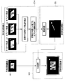
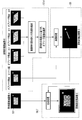
- FIG. 1 shows a block diagram of an ultrasonic diagnostic apparatus 1 according to this embodiment.
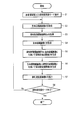
- FIG. 2 is a flowchart showing a flow of processing (puncture support processing) according to the present puncture support function.
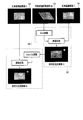
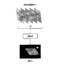
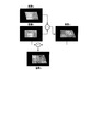
- FIG. 3 is a diagram conceptually showing the processing of steps S2 to S7 in FIG.
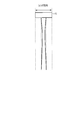
- FIG. 4 is a diagram showing an example of the beam width in the lens direction when a one-dimensional array probe is used.
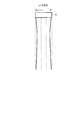
- FIG. 5 is a diagram showing an example of the beam width in the lens direction when a two-dimensional array probe is used.
- FIG. 6 is a diagram for explaining the process of step S3 according to the second modification.
- FIG. 7 is a diagram for explaining the process of step S4 according to the second modification.
- FIG. 1 shows a block diagram of an ultrasonic diagnostic apparatus 1 according to this embodiment.
- FIG. 2 is a flowchart showing a flow of processing (puncture support processing) according to the present puncture support function.
- FIG. 3 is a diagram conceptually showing
- FIG. 8 is a diagram for explaining the process of step S3 according to the third modification.
- FIG. 9 is a diagram for explaining the process of step S4 according to the fourth modification.
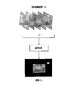
- FIG. 10 is a diagram for explaining the effect of the ultrasonic diagnostic apparatus according to the present embodiment.
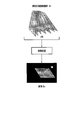
- FIG. 11 is a diagram conceptually illustrating a puncture support process according to the second embodiment.
- FIG. 12 is a diagram conceptually illustrating a puncture support process according to Modification 1 of the second embodiment.
- FIG. 13 is a diagram conceptually illustrating a puncture support process according to Modification 2 of the second embodiment.
- FIG. 14 is a diagram for explaining processing in a conventional ultrasonic diagnostic apparatus.
- FIG. 1 is a block diagram of an ultrasonic diagnostic apparatus 1 according to this embodiment.
- the ultrasonic diagnostic apparatus 1 includes an ultrasonic probe 12, an input device 13, a monitor 14, an ultrasonic transmission unit 21, an ultrasonic reception unit 22, a B-mode processing unit 23, a Doppler processing unit 24, A RAW data memory 25, a volume data generation unit 26, an image processing unit 28, a display processing unit 30, a control processor (CPU) 31, a puncture support image generation unit 32, a storage unit 33, and an interface unit 35 are provided.
- CPU control processor
- the ultrasonic probe 12 is a device (probe) that transmits ultrasonic waves to a subject and receives reflected waves from the subject based on the transmitted ultrasonic waves, and is arranged in a plurality at the tip thereof.
- a piezoelectric vibrator, a matching layer, a backing material, and the like are included.
- the piezoelectric vibrator transmits an ultrasonic wave in a desired direction in the scan region based on a drive signal from the ultrasonic transmission unit 21, and converts a reflected wave from the subject into an electric signal.
- the matching layer is an intermediate layer provided in the piezoelectric vibrator for efficiently propagating ultrasonic energy.
- the backing material prevents ultrasonic waves from propagating backward from the piezoelectric vibrator.
- the transmitted ultrasonic waves are successively reflected by the discontinuous surface of the acoustic impedance of the body tissue and received by the ultrasonic probe 12 as an echo signal.
- the amplitude of this echo signal depends on the difference in acoustic impedance at the discontinuous surface that is to be reflected.
- the echo when the transmitted ultrasonic pulse is reflected by the moving bloodstream undergoes a frequency shift due to the Doppler effect depending on the velocity component in the ultrasonic transmission / reception direction of the moving body.
- the ultrasonic probe 12 uses a one-dimensional ultrasonic probe in which ultrasonic transducers are arranged in a predetermined direction as an example.
- the input device 13 is connected to the device main body 11, and various switches, buttons, and tracks for incorporating various instructions, conditions, region of interest (ROI) setting instructions, various image quality condition setting instructions, etc. from the operator into the device main body 11. It has a ball, mouse, keyboard, etc.
- the input device 13 has a dedicated switch for inputting a diagnostic region, a dedicated knob for controlling the range of color data used for imaging, and the transparency (opacity of voxels) in the near-luminal blood flow rendering function described later. ) Has special knobs for controlling.
- the monitor 14 displays in-vivo morphological information and blood flow information as an image based on the video signal from the display processing unit 30.
- the ultrasonic transmission unit 21 has a trigger generation circuit, a delay circuit, a pulsar circuit, and the like (not shown).
- a trigger pulse for forming a transmission ultrasonic wave is repeatedly generated at a predetermined rate frequency fr Hz (cycle: 1 / fr second).
- a delay time required for focusing the ultrasonic wave into a beam shape for each channel and determining the transmission directivity is given to each trigger pulse.
- the pulsar circuit applies a drive pulse to the probe 12 at a timing based on the trigger pulse.
- the ultrasonic receiving unit 22 has an amplifier circuit, an A / D converter, a delay circuit, an adder and the like not shown.
- the amplifier circuit amplifies the echo signal captured via the probe 12 for each channel.
- the A / D converter converts the amplified analog echo signal into a digital echo signal.
- the delay circuit determines the reception directivity for the digitally converted echo signal, gives a delay time necessary for performing the reception dynamic focus, and then performs an addition process in the adder. By this addition, the reflection component from the direction corresponding to the reception directivity of the echo signal is emphasized, and a comprehensive beam for ultrasonic transmission / reception is formed by the reception directivity and the transmission directivity.
- the B-mode processing unit 23 receives the echo signal from the receiving unit 22, performs logarithmic amplification, envelope detection processing, and the like, and generates data in which the signal intensity is expressed by brightness.
- the Doppler processing unit 24 extracts a blood flow signal from the echo signal received from the reception unit 22 and generates blood flow data. Extraction of blood flow is usually performed by CFM (Color Flow Mapping). In this case, the blood flow signal is analyzed, and blood flow information such as average velocity, dispersion, power, etc. is obtained for multiple points as blood flow data.
- CFM Color Flow Mapping
- the RAW data memory 25 generates B-mode RAW data, which is B-mode data on a three-dimensional ultrasonic scanning line, using a plurality of B-mode data received from the B-mode processing unit 23.
- the RAW data memory 25 generates blood flow RAW data, which is blood flow data on a three-dimensional ultrasonic scanning line, using a plurality of blood flow data received from the Doppler processing unit 24.
- a spatial smoothing may be performed by inserting a three-dimensional filter after the RAW data memory 25.
- the volume data generation unit 26 generates B-mode volume data blood flow volume data from the B-mode RAW data received from the RAW data memory 25 by executing RAW-voxel conversion.
- the image processing unit 28 is a predetermined image such as volume rendering, multi-section conversion display (MPR: multi-planar reconstruction), maximum value projection display (MIP: maximum-intensity-projection). Process.
- MPR multi-section conversion display
- MIP maximum value projection display
- a two-dimensional filter may be inserted after the image processing unit 28 to perform spatial smoothing.
- the display processing unit 30 executes various processes such as dynamic range, brightness (brightness), contrast, ⁇ curve correction, and RGB conversion on various image data generated and processed in the image processing unit 28.
- the control processor 31 has a function as an information processing apparatus (computer) and controls the operation of the main body of the ultrasonic diagnostic apparatus.
- the control processor 31 reads out a dedicated program for realizing a puncture support support function, which will be described later, from the storage unit 33, develops it on its own memory, and executes arithmetic / control related to various processes.
- the puncture support image generation unit 32 generates an image for supporting puncture based on a puncture support output function described later.
- the storage unit 33 is a dedicated program for realizing a puncture support support function described later, a diagnostic information (patient ID, doctor's findings, etc.), a diagnostic protocol, transmission / reception conditions, a program for realizing a speckle removal function, A body mark generation program, a conversion table for presetting the range of color data used for imaging for each diagnostic part, and other data groups are stored. Further, it is also used for storing images in an image memory (not shown) as required. Data in the storage unit 33 can also be transferred to an external peripheral device via the interface unit 35.
- the interface unit 35 is an interface related to the input device 13, the network, and a new external storage device (not shown). Data such as ultrasonic images and analysis results obtained by the apparatus can be transferred by the interface unit 32 to another apparatus via a network.
- Puncture support function Next, the puncture support function that the ultrasonic diagnostic apparatus 1 has will be described.
- this function sets an area to be scanned by ultrasound so as not to be detached from the puncture needle, and the living tissue and the puncture needle And generate and provide a puncture support image that is always well imaged.
- FIG. 2 is a flowchart showing a flow of processing according to the present puncture support function (puncture support processing).
- Puncture support processing the content of the process performed in each step shown in the flowchart will be described.
- Step S1 Input of patient information and selection of puncture support mode Input of patient information, examination information and the like through the operation unit 33 and selection of a puncture support mode in which the present puncture support function is executed are executed (step S1). Various information inputted and selected is automatically stored in the storage device 29. In addition, the control unit 31 activates a program for executing the puncture support function in response to the selection operation of the puncture support mode.
- Step S2 ultrasonic transmission / reception is performed by an imaging method or transmission / reception setting in which the biological tissue is well depicted, such as tissue harmonic imaging, and a biological high-definition image A in which the biological tissue is visualized with high definition is acquired ( Step S2).
- the biological high-definition image A is not limited to an image captured by tissue harmonic imaging, and may be an image captured using a received signal including a fundamental wave component in the frequency band.
- an ultrasonic image over a plurality of frames may be an image captured by tissue harmonic imaging, or an image captured with the fundamental wave component included in the frequency band.
- a pulse subtraction method (a technique for obtaining a reception data in a harmonic band by adding a plurality of pulses having different polarities or phases) may be used.
- the number of added pulses is not particularly limited, and an arbitrary number of pulses may be used.
- the pulse subtraction method may be executed to acquire ultrasonic data over a plurality of frames (a plurality of volumes), and an addition process and a difference process using these may be executed to generate the biological high-definition image A. .
- a puncture needle emphasized image B is acquired by executing an oblique scan in which the direction is substantially perpendicular to the longitudinal direction of the needle (step S3).
- the transmission / reception setting is not limited to the above contents, and for example, using at least one of the element pitch of the ultrasonic transducer of the ultrasonic probe 12 to be used, the transmission / reception frequency characteristics of the ultrasonic transducer, the oblique angle, and the like. Transmission / reception conditions can be controlled. In particular, it is theoretically known that the following equation should be satisfied in order to prevent the appearance of grating lobes.
- step S3 the control processor 31 sets the wavelength (or frequency) of the transmission waveform, the reception center frequency, and the reception frequency band either automatically or by manual input from the input device 13 so as to satisfy the conditional expression (1).
- the control processor 31 sets the wavelength (or frequency) of the transmission waveform, the reception center frequency, and the reception frequency band either automatically or by manual input from the input device 13 so as to satisfy the conditional expression (1).
- the conditional expression (1) there is no transmission / reception condition that satisfies the conditional expression (1). In such a case, it is preferable to select a condition in which a grating lobe does not enter the image as much as possible based on the conditional expression (1).
- the oblique angle is preferably set so that the ultrasonic beam is transmitted to the puncture needle at an angle that is perpendicular or nearly perpendicular.
- the guide line of the puncture needle can be displayed on the ultrasonic image by registering the angle of the puncture needle with respect to the adapter in the ultrasonic diagnostic apparatus.
- the control processor 31 automatically determines the oblique angle based on the registered angle of the puncture needle.
- the control processor 31 automatically determines the oblique angle based on the position detected by the position sensor.
- the oblique angle may be automatically determined based on the direction of the puncture needle. Furthermore, the oblique angle may be set and adjusted by manual input from the input device 13 with reference to the direction of the puncture needle on the ultrasonic image.
- Step S4 the main lobe scanning angle is set to 0, and transmission / reception conditions other than the scanning angle are substantially the same as the conditions when the puncture needle emphasized image B is acquired (that is, the transmission / reception conditions set in step S3).
- a sound wave transmission / reception is executed to create a biological tissue image C (step S4).
- step S3 and step S4 can be switched as necessary.
- the ultrasonic scanning area in step S3 and the ultrasonic scanning area in step S4 do not have to be the same. That is, in step S3, an ultrasonic scanning region may be set so as to meet the purpose of emphasizing and visualizing the puncture needle, while in step S4, it is included in the puncture needle emphasized image B.
- the ultrasonic scanning region may be set so as to meet the purpose of canceling the tissue (for example, including at least the tissue region included in the puncture needle emphasized image B).
- the puncture support image generation unit 32 generates a puncture needle extraction image D by image processing using the puncture needle emphasized image B and the biological tissue image C (step S5). For example, the puncture support image generation unit 32 compares the luminance value of the puncture needle emphasized image B and the luminance value of the biological tissue image C for each spatially corresponding position, and the luminance value of the biological tissue image C is large. Is assigned 0, and when the luminance value of the puncture needle emphasized image B is large, the luminance value of the image B is assigned to each position, thereby generating the puncture needle extraction image D.
- the luminance value of the puncture needle included in the puncture needle emphasis image B is assigned to the position corresponding to the puncture needle on the puncture needle extraction image D, while the area other than the puncture needle on the puncture needle extraction image D is assigned. Is assigned a luminance value of 0. Therefore, the puncture needle extraction image D is a good image obtained by extracting the puncture needle.
- the method of generating the puncture needle extraction image D is not limited to the comparison of luminance values as described above.
- the luminance value of the puncture needle emphasized image B and the luminance value of the biological tissue image C are averaged at each spatially corresponding position, or an addition / subtraction process (addition process, difference process) or the like is performed. May be assigned as the luminance value at each position to generate the puncture needle extraction image D.
- the gain and the dynamic range are set for at least one of the puncture needle emphasized image B and the biological tissue image C so that the puncture needle or the biological tissue is emphasized (or suppressed). You may make it adjust at least one of these.
- the difference in acoustic impedance is very large between a curable substance such as a puncture needle and a living tissue. For this reason, the reflection signal from the puncture needle is very large compared to the reflection signal of the biological tissue, and the puncture needle is displayed with higher luminance in the puncture needle emphasized image B than the surrounding biological tissue.
- the puncture needle emphasized image B by lowering the gain of the puncture needle emphasized image B relative to the biological tissue image C, or so that the tissue of the puncture needle emphasized image B and the tissue of the biological tissue image C have the same brightness.
- the gain By correcting the gain, the luminance at the position corresponding to the living tissue can be reduced to 0 when the puncture needle extraction image D is generated.
- the puncture needle corresponding to the high luminance region can be extracted effectively.
- the puncture support image generation unit 32 uses the puncture needle extraction image D in which the puncture needle is well imaged and the living body high-definition image A in which the living tissue is imaged in high definition, to perform the puncture support.
- An image E is generated (step S6).
- the puncture support image generation unit 32 determines the brightness value of the living body high-definition image A in which only the living body is imaged in high definition and the brightness value of the puncture needle extraction image D from which the puncture needle is extracted.
- the puncture support image E is an image in which a high-luminance needle image is displayed on the living body high-definition image A with good image quality. Further, by performing at least one of addition processing, difference processing, maximum value projection processing, minimum value projection processing, and averaging processing using the puncture needle extraction image D and the living body high-definition image A, puncture The support image E may be generated.
- the generation method of the puncture support image E is not limited to the comparison of luminance values as described above.
- the luminance value of the puncture needle extraction image D and the luminance value of the biological high-definition image A are averaged at each spatially corresponding position, addition / subtraction processing, etc. are executed, and the obtained value is used as the luminance value at each position
- the puncture support image E may be generated.
- at least one of the gain and the dynamic range may be adjusted for at least one of the puncture needle extraction image D and the living body high-definition image A.
- the puncture needle extraction image D is a display of only high-luminance needles.
- the signal from the tissue region can be suppressed or eliminated by narrowing the dynamic range of the puncture needle extraction image D, and the region corresponding to the puncture needle can be illuminated with high luminance by increasing the gain.
- the gain and dynamic range are adjusted by generating a histogram relating to the luminance of the puncture needle extraction image D, and automatically by threshold processing using the generated histogram or manually by manual operation from the input device 13. Can be executed.
- Step S8 The above-described processing of steps S2 to S7 is repeatedly executed sequentially during puncture.
- FIG. 3 is a diagram conceptually showing the processing of steps S2 to S7 in FIG. As shown in the figure, each process corresponding to each of steps S2 to S7 is executed, and the puncture support image E is sequentially updated and displayed. The operator can easily visually recognize the relative positional relationship between the living tissue and the puncture needle by observing the puncture support image E displayed in real time.
- the ultrasonic probe 12 is a one-dimensional array probe is taken as an example.
- a 1.5-dimensional array probe or a two-dimensional array probe may be adopted as the ultrasonic probe 12. Accordingly, the beam width in the lens direction when using the two-dimensional array probe (see FIG. 5) is compared with the beam width in the lens direction (slice direction) when using the one-dimensional array probe (see FIG. 4).
- the puncture needle emphasized image group Bn and the biological tissue image C can be captured. As a result, even when the position of the puncture needle is slightly shifted from directly below the ultrasonic probe 12, the puncture needle can always be imaged appropriately.
- the beam width in the lens direction is increased in the imaging of the puncture needle emphasized image group Bn
- the beam width in the lens direction is also increased in the imaging of the biological tissue image C (the puncture needle emphasized image). It is desirable that the beam width is the same as that in imaging of the group Bn.
- step S3 When a two-dimensional array probe is used as the ultrasonic probe 12, the processes in steps S3, S4, and S5 may be performed as follows. That is, in the process of step S3, as shown in FIG. 6, the puncture needle emphasized image group Bn is acquired by n oblique scans parallel to the slice direction, and the luminance value is averaged for each spatially corresponding position. Alternatively, addition / subtraction processing or the like is executed to generate the image Ba. Further, in the process of step S4, as shown in FIG. 7, the biological tissue image group Cn is acquired by the normal scan obtained by the n normal scans parallel to the slice direction, and the luminance value is obtained at each spatially corresponding position. The averaging process or the addition / subtraction process is executed to generate the image Ca. The puncture needle extraction image D may be generated by performing the above-described brightness value comparison processing in step S5 using the image Ba and the image Ca thus obtained.
- the puncture needle is adjusted by the weight of the average probe or the addition process according to the distance from the position immediately below the ultrasonic probe 12 of each image. It is possible to visually recognize how far it is from directly below. For example, when the puncture needle is away from just below the ultrasound probe 12 by reducing the weighting as it moves away from directly below the ultrasound probe 12, the puncture needle of the puncture support image E has low (dark) luminance. On the other hand, when the puncture needle is present directly below the ultrasonic probe 12, the puncture needle of the puncture support image E is displayed with high (bright) luminance. The surgeon can easily grasp the positional relationship between the ultrasonic probe 12 (and the scanning region) and the puncture needle based on the luminance of the puncture needle displayed in the puncture support image E.
- step S3 When a mechanical four-dimensional probe (probe capable of scanning a three-dimensional region over time by oscillating a one-dimensional transducer array) is used as the ultrasonic probe 12, steps S3 and S4 are performed as in the second modification. , S5 may be performed as follows. That is, in the process of step S3, as shown in FIG. 8, the puncture corresponding to n scanning sections is performed by executing an oblique scan while moving (swinging) the scanning section along the slice direction. The needle-enhanced image group Bn is acquired, and the luminance value averaging process or addition / subtraction process is executed for each spatially corresponding position to generate the image Ba. Further, in the process of step S4, as shown in FIG.
- the normal scan is executed while moving (swinging) the scan section so as to sway along the slice direction, thereby corresponding to n scan sections.
- the biological tissue image group Cn is acquired, and luminance value averaging processing or addition / subtraction processing is executed for each spatially corresponding position to generate an image Ca.
- the puncture needle extraction image D may be generated by performing the above-described brightness value comparison processing in step S5 using the image Ba and the image Ca thus obtained. Of course, it is possible to perform the same weighting process as in the second modification.
- the ultrasonic diagnostic apparatus when performing a puncture operation while monitoring a living tissue and a puncture needle, as shown in FIG. 10, using a scanned region set so as not to be removed from the puncture needle.
- a puncture needle-enhanced image is acquired by an oblique scan
- a biological tissue image is acquired by a normal scan that differs only in the transmission / reception direction from the puncture needle-enhanced image.
- Generated Since the puncture needle-emphasized image and the biological tissue image are acquired under substantially the same transmission / reception conditions except for the transmission / reception direction, the puncture needle from which the biological tissue is suitably removed and the puncture needle is extracted using both An extracted image can be generated.
- a puncture support image including a high-definition image of a biological tissue and a puncture needle suitably extracted using the puncture needle extraction image thus obtained and a biological high-definition image obtained by tissue harmonic imaging or the like Is generated and displayed.
- the ultrasonic diagnostic apparatus 1 acquires a puncture needle emphasized image B (or a puncture needle emphasized image group Bn.
- the puncture needle emphasized image B is taken as an example) corresponding to each of a plurality of oblique angles. Then, based on the angle of the puncture needle inserted into the subject, the puncture needle-enhanced image B corresponding to the oblique angle optimum for imaging the puncture needle is selected, and the puncture needle extraction image D is generated using this image. Is.
- step S3 and step S5 when the puncture support process according to the present embodiment is compared with the puncture support process according to the first embodiment, the processes in steps S3 and S5 in FIG. 2 are different.
- step S3 and step S5 according to the present embodiment will be mainly described.
- FIG. 11 is a diagram conceptually showing a puncture support process according to the second embodiment (the step numbers in FIG. 11 correspond to the step numbers shown in FIG. 2).
- the corresponding puncture needle emphasized image B of each of the plurality of oblique angles is acquired.
- the transmission / reception setting at each oblique angle is the same as that in the first embodiment.
- the control processor 31 detects the insertion angle ⁇ of the puncture needle with respect to the subject.
- the detection of the insertion angle ⁇ of the puncture needle can be realized, for example, by performing a line segment detection process using at least one of the plurality of puncture needle emphasized images B.
- the insertion angle may be detected by a detector provided in the puncture needle adapter.
- the control processor 31 uses the puncture needle emphasized image D used to generate the puncture needle emphasized image D from the plurality of puncture needle emphasized images B corresponding to the plurality of oblique angles based on the detected puncture angle ⁇ of the puncture needle. Select B.
- step S5 the puncture support image generation unit 32 generates a puncture needle extraction image D by image processing using the selected puncture needle emphasis image B and biological tissue image C.
- the specific contents of the image processing are the same as in the first embodiment.
- control processor 31 controls at least one of the plurality of oblique angles and the number of oblique angles (the number of oblique directions) in accordance with the angle of the puncture needle detected in step S3 and its change over time. .
- the transmission / reception conditions are determined and controlled according to the determined plurality of oblique angles and the number of oblique angles.
- the angle of the puncture needle inserted into the subject varies from surgery to surgery.
- the puncture needle emphasized image B corresponding to each of the plurality of oblique angles is acquired, and the puncture needle is visualized based on the angle of the puncture needle inserted into the subject.
- a puncture needle emphasis image B corresponding to the optimum oblique angle is selected, and a puncture needle extraction image D and a puncture support image E can be generated using this. Therefore, in the puncture operation, the puncture needle can always be suitably imaged, which can contribute to improvement of the safety and quality of the puncture operation.
- the puncture needle emphasized image B corresponding to the optimum oblique angle is selected from the plurality of oblique images.
- the maximum value projection image of the plurality of oblique images is selected as the puncture needle. It may be used as the enhanced image B. If the accuracy of the puncture angle detection is low, it is assumed that an optimal puncture needle emphasis image cannot be selected. Therefore, an image in which the puncture needle is always emphasized can be obtained by performing maximum value projection without detection. It becomes possible to create.
- the processing is not limited to the maximum value and the projection, and may be average, addition, or the like.
- the puncture support function according to each of the embodiments can also be realized by installing a program for executing the processing in a computer such as a workstation and developing these on a memory.
- a program capable of causing the computer to execute the method is stored in a recording medium such as a magnetic disk (floppy (registered trademark) disk, hard disk, etc.), an optical disk (CD-ROM, DVD, etc.), or a semiconductor memory. It can also be distributed.
- the puncture support process is executed using the luminance value after image reconstruction.
- puncture support processing may be executed using RAW data before image reconstruction.
- an ultrasonic diagnostic apparatus and an ultrasonic diagnostic apparatus control method capable of monitoring a living tissue and a puncture needle with good and high-quality images when performing a puncture.
Landscapes
- Health & Medical Sciences (AREA)
- Life Sciences & Earth Sciences (AREA)
- Engineering & Computer Science (AREA)
- Radiology & Medical Imaging (AREA)
- Heart & Thoracic Surgery (AREA)
- Biophysics (AREA)
- Nuclear Medicine, Radiotherapy & Molecular Imaging (AREA)
- Pathology (AREA)
- Veterinary Medicine (AREA)
- Biomedical Technology (AREA)
- Physics & Mathematics (AREA)
- Medical Informatics (AREA)
- Molecular Biology (AREA)
- Surgery (AREA)
- Animal Behavior & Ethology (AREA)
- General Health & Medical Sciences (AREA)
- Public Health (AREA)
- Computer Vision & Pattern Recognition (AREA)
- Ultra Sonic Daignosis Equipment (AREA)
Abstract
La présente invention concerne une image favorable et de haute qualité de tissus biologiques et une aiguille pour ponction. L'invention concerne un dispositif de diagnostic ultrasonore utilisé pour observer la position et la direction d'insertion d'une aiguille pour ponction chez un sujet dans une paracentèse, le dispositif comprenant : une unité d'acquisition de données qui acquiert une pluralité de premières données ultrasonores par exécution d'un premier balayage ultrasonore à un premier réglage de transmission/réception chez un sujet, qui acquiert une pluralité de deuxièmes données ultrasonores par exécution d'un second balayage ultrasonore à un second réglage de transmission/réception chez un sujet et qui acquiert une pluralité de troisièmes données ultrasonores par exécution d'un troisième balayage ultrasonore à un troisième réglage transmission/réception ; et une unité de transmission d'image qui produit une image de tissu qui affiche des tissus biologiques à l'aide des premières données ultrasonores, qui produit une image de la ponction qui affiche l'aiguille pour ponction sur la base du traitement d'image à l'aide des deuxièmes données ultrasonores et des troisièmes données ultrasonores et qui produit une image de synthèse dans laquelle les tissus biologiques et l'aiguille pour ponction sont visualisés à l'aide de l'image des tissus et de l'image de la ponction.
Priority Applications (2)
| Application Number | Priority Date | Filing Date | Title |
|---|---|---|---|
| CN201380003446.3A CN103889337B (zh) | 2012-10-23 | 2013-10-23 | 超声波诊断装置以及超声波诊断装置控制方法 |
| US14/694,391 US10278670B2 (en) | 2012-10-23 | 2015-04-23 | Ultrasound diagnostic apparatus and method of controlling ultrasound diagnostic apparatus |
Applications Claiming Priority (2)
| Application Number | Priority Date | Filing Date | Title |
|---|---|---|---|
| JP2012-234086 | 2012-10-23 | ||
| JP2012234086 | 2012-10-23 |
Related Child Applications (1)
| Application Number | Title | Priority Date | Filing Date |
|---|---|---|---|
| US14/694,391 Continuation US10278670B2 (en) | 2012-10-23 | 2015-04-23 | Ultrasound diagnostic apparatus and method of controlling ultrasound diagnostic apparatus |
Publications (1)
| Publication Number | Publication Date |
|---|---|
| WO2014065338A1 true WO2014065338A1 (fr) | 2014-05-01 |
Family
ID=50544713
Family Applications (1)
| Application Number | Title | Priority Date | Filing Date |
|---|---|---|---|
| PCT/JP2013/078740 WO2014065338A1 (fr) | 2012-10-23 | 2013-10-23 | Dispositif de diagnostic ultrasonore et procédé de commande de dispositif de diagnostic ultrasonore |
Country Status (4)
| Country | Link |
|---|---|
| US (1) | US10278670B2 (fr) |
| JP (1) | JP6257997B2 (fr) |
| CN (1) | CN103889337B (fr) |
| WO (1) | WO2014065338A1 (fr) |
Cited By (2)
| Publication number | Priority date | Publication date | Assignee | Title |
|---|---|---|---|---|
| CN106308895A (zh) * | 2016-09-20 | 2017-01-11 | 深圳华声医疗技术有限公司 | 穿刺增强方法、装置及系统 |
| CN117045327A (zh) * | 2023-10-11 | 2023-11-14 | 深圳华声医疗技术股份有限公司 | 超声穿刺针显影方法、装置、超声设备及存储介质 |
Families Citing this family (28)
| Publication number | Priority date | Publication date | Assignee | Title |
|---|---|---|---|---|
| EP2488107B1 (fr) * | 2009-10-12 | 2017-03-08 | Acist Medical Systems, Inc. | Système ultrasonore intravasculaire pour une imagerie co-enregistrée |
| JP6110760B2 (ja) | 2013-08-27 | 2017-04-05 | 富士フイルム株式会社 | 超音波診断装置および超音波診断装置の作動方法 |
| JP6447071B2 (ja) * | 2013-12-11 | 2019-01-09 | コニカミノルタ株式会社 | 超音波診断装置、超音波画像処理方法、および、プログラム |
| CN107427288B (zh) | 2015-04-03 | 2020-04-21 | 富士胶片株式会社 | 声波图像生成装置及方法 |
| WO2017029830A1 (fr) * | 2015-08-20 | 2017-02-23 | コニカミノルタ株式会社 | Appareil d'imagerie de diagnostic à ultrasons |
| JP6044749B1 (ja) * | 2015-08-20 | 2016-12-14 | コニカミノルタ株式会社 | 超音波画像診断装置 |
| JP6705134B2 (ja) * | 2015-08-21 | 2020-06-03 | コニカミノルタ株式会社 | 超音波画像診断装置、超音波画像処理方法及び超音波画像処理プログラム |
| CN105496515B (zh) * | 2015-12-04 | 2018-07-17 | 深圳华声医疗技术股份有限公司 | 穿刺增强方法及系统 |
| US11369337B2 (en) | 2015-12-11 | 2022-06-28 | Acist Medical Systems, Inc. | Detection of disturbed blood flow |
| CN105581813A (zh) * | 2015-12-22 | 2016-05-18 | 汕头市超声仪器研究所有限公司 | 一种基于编码器的全自动穿刺针显影增强方法 |
| US10835212B2 (en) * | 2016-04-01 | 2020-11-17 | Canon Medical Systems Corporation | Medical image processing apparatus |
| JP6871016B2 (ja) * | 2016-04-01 | 2021-05-12 | キヤノンメディカルシステムズ株式会社 | 超音波診断装置および超音波画像生成プログラム |
| EP3449838B1 (fr) * | 2016-04-26 | 2023-09-20 | Telefield Medical Imaging Limited | Procédé et dispositif d'imagerie |
| JP2017209324A (ja) * | 2016-05-26 | 2017-11-30 | セイコーエプソン株式会社 | 超音波測定装置 |
| CN106236140B (zh) * | 2016-08-25 | 2019-11-08 | 成都优途科技有限公司 | 一种超声成像方法、装置及系统 |
| EP3512432B1 (fr) * | 2016-09-16 | 2021-02-24 | Koninklijke Philips N.V. | Appareil et procédé de détection d'un outil d'intervention |
| US10932749B2 (en) * | 2016-11-09 | 2021-03-02 | Fujifilm Sonosite, Inc. | Ultrasound system for enhanced instrument visualization |
| RU2756028C2 (ru) * | 2016-11-17 | 2021-09-24 | Конинклейке Филипс Н.В. | Дистанционная ультразвуковая диагностика с управляемым качеством отображения изображений |
| WO2018195824A1 (fr) * | 2017-04-26 | 2018-11-01 | 深圳迈瑞生物医疗电子股份有限公司 | Dispositif d'imagerie ultrasonore, procédé d'amélioration d'image ultrasonore et procédé d'affichage de perforation guidée |
| CN107361793B (zh) * | 2017-07-18 | 2021-03-30 | 深圳开立生物医疗科技股份有限公司 | 超声波成像方法、系统及超声成像设备 |
| WO2019145183A1 (fr) * | 2018-01-23 | 2019-08-01 | Koninklijke Philips N.V. | Système d'imagerie ultrasonore fournissant un guidage d'insertion d'aiguille |
| WO2019205006A1 (fr) * | 2018-04-25 | 2019-10-31 | 深圳迈瑞生物医疗电子股份有限公司 | Procédé d'imagerie ultrasonore et dispositif d'imagerie ultrasonore |
| JP7059843B2 (ja) * | 2018-07-13 | 2022-04-26 | コニカミノルタ株式会社 | 超音波診断装置、超音波画像表示方法及びプログラム |
| CN109567929B (zh) * | 2018-08-20 | 2021-05-14 | 云南大学 | 一种超声谐波加权定征参数差分成像的微波消融监测方法 |
| US11024034B2 (en) | 2019-07-02 | 2021-06-01 | Acist Medical Systems, Inc. | Image segmentation confidence determination |
| CN112137693B (zh) * | 2020-09-08 | 2023-01-03 | 深圳蓝影医学科技股份有限公司 | 四维超声引导穿刺的成像方法及装置 |
| CN113855188A (zh) * | 2021-10-20 | 2021-12-31 | 无锡祥生医疗科技股份有限公司 | 超声扫查设备、成像设备、穿刺针监控方法及系统 |
| CN115530875A (zh) * | 2022-10-26 | 2022-12-30 | 杭州永锦科技有限公司 | 超声波成像方法、装置、设备及可读存储介质 |
Citations (3)
| Publication number | Priority date | Publication date | Assignee | Title |
|---|---|---|---|---|
| JP2008178470A (ja) * | 2007-01-23 | 2008-08-07 | Toshiba Corp | 超音波診断装置 |
| JP2010183935A (ja) * | 2009-02-10 | 2010-08-26 | Toshiba Corp | 超音波診断装置及び超音波診断装置の制御プログラム |
| WO2011127191A1 (fr) * | 2010-04-07 | 2011-10-13 | Nikolaos Pagoulatos | Systèmes et procédés d'imagerie améliorée d'objets dans image |
Family Cites Families (9)
| Publication number | Priority date | Publication date | Assignee | Title |
|---|---|---|---|---|
| US6524247B2 (en) * | 2001-05-15 | 2003-02-25 | U-Systems, Inc. | Method and system for ultrasound imaging of a biopsy needle |
| US6951542B2 (en) * | 2002-06-26 | 2005-10-04 | Esaote S.P.A. | Method and apparatus for ultrasound imaging of a biopsy needle or the like during an ultrasound imaging examination |
| JP4405182B2 (ja) * | 2002-10-10 | 2010-01-27 | 株式会社東芝 | 超音波診断装置 |
| JP2006150069A (ja) * | 2004-10-20 | 2006-06-15 | Toshiba Corp | 超音波診断装置及びその制御方法 |
| JP2008012150A (ja) * | 2006-07-07 | 2008-01-24 | Toshiba Corp | 超音波診断装置、及び超音波診断装置の制御プログラム |
| JP5495593B2 (ja) * | 2009-03-23 | 2014-05-21 | 株式会社東芝 | 超音波診断装置及び穿刺支援用制御プログラム |
| JP5575534B2 (ja) * | 2010-04-30 | 2014-08-20 | 株式会社東芝 | 超音波診断装置 |
| JP6000569B2 (ja) | 2011-04-01 | 2016-09-28 | 東芝メディカルシステムズ株式会社 | 超音波診断装置及び制御プログラム |
| WO2014002963A1 (fr) * | 2012-06-25 | 2014-01-03 | 株式会社東芝 | Appareil de diagnostic par ultrasons et procédé de traitement d'image |
-
2013
- 2013-10-23 WO PCT/JP2013/078740 patent/WO2014065338A1/fr active Application Filing
- 2013-10-23 CN CN201380003446.3A patent/CN103889337B/zh active Active
- 2013-10-23 JP JP2013220667A patent/JP6257997B2/ja active Active
-
2015
- 2015-04-23 US US14/694,391 patent/US10278670B2/en active Active
Patent Citations (3)
| Publication number | Priority date | Publication date | Assignee | Title |
|---|---|---|---|---|
| JP2008178470A (ja) * | 2007-01-23 | 2008-08-07 | Toshiba Corp | 超音波診断装置 |
| JP2010183935A (ja) * | 2009-02-10 | 2010-08-26 | Toshiba Corp | 超音波診断装置及び超音波診断装置の制御プログラム |
| WO2011127191A1 (fr) * | 2010-04-07 | 2011-10-13 | Nikolaos Pagoulatos | Systèmes et procédés d'imagerie améliorée d'objets dans image |
Cited By (3)
| Publication number | Priority date | Publication date | Assignee | Title |
|---|---|---|---|---|
| CN106308895A (zh) * | 2016-09-20 | 2017-01-11 | 深圳华声医疗技术有限公司 | 穿刺增强方法、装置及系统 |
| CN117045327A (zh) * | 2023-10-11 | 2023-11-14 | 深圳华声医疗技术股份有限公司 | 超声穿刺针显影方法、装置、超声设备及存储介质 |
| CN117045327B (zh) * | 2023-10-11 | 2023-12-08 | 深圳华声医疗技术股份有限公司 | 超声穿刺针显影方法、装置、超声设备及存储介质 |
Also Published As
| Publication number | Publication date |
|---|---|
| JP6257997B2 (ja) | 2018-01-10 |
| US10278670B2 (en) | 2019-05-07 |
| JP2014100556A (ja) | 2014-06-05 |
| CN103889337A (zh) | 2014-06-25 |
| US20150223776A1 (en) | 2015-08-13 |
| CN103889337B (zh) | 2016-11-02 |
Similar Documents
| Publication | Publication Date | Title |
|---|---|---|
| JP6257997B2 (ja) | 超音波診断装置及び超音波診断装置制御方法 | |
| JP6734079B2 (ja) | 医用診断装置、および医用解析プログラム | |
| JP5972569B2 (ja) | 超音波診断装置、超音波画像処置装置、医用画像診断装置及び超音波画像処理プログラム | |
| US10743845B2 (en) | Ultrasound diagnostic apparatus and method for distinguishing a low signal/noise area in an ultrasound image | |
| JP5438985B2 (ja) | 超音波診断装置及び超音波診断装置の制御プログラム | |
| JP5868067B2 (ja) | 医用画像診断装置、画像処理装置及び方法 | |
| JP5707148B2 (ja) | 医用画像診断装置及び医用画像処理装置 | |
| JP5395396B2 (ja) | 超音波診断装置、医用画像処理装置、及び医用画像処理プログラム | |
| US8882671B2 (en) | Ultrasonic diagnostic device, ultrasonic image processing apparatus, ultrasonic image acquiring method and ultrasonic diagnosis display method | |
| JP5680654B2 (ja) | 超音波診断装置及び超音波画像表示方法 | |
| JP6176839B2 (ja) | 超音波診断装置 | |
| US10524768B2 (en) | Medical image diagnostic apparatus and medical image processing apparatus | |
| JP5689591B2 (ja) | 超音波診断装置及び超音波画像処理プログラム | |
| JP2010284516A (ja) | 超音波診断装置、超音波画像処理装置及び超音波画像処理プログラム | |
| JP7392093B2 (ja) | 超音波診断装置、及び制御プログラム | |
| JP2006314689A (ja) | 超音波診断装置及び超音波診断装置制御プログラム | |
| JP5942217B2 (ja) | 超音波診断装置、超音波画像処理装置及び超音波画像処理プログラム | |
| JP2007195867A (ja) | 超音波診断装置及び超音波画像表示プログラム | |
| JP2012075794A (ja) | 超音波診断装置、医用画像処理装置及び医用画像処理プログラム | |
| JP2012176232A (ja) | 超音波診断装置、超音波画像処理装置及び超音波画像処理プログラム | |
| JP2007007200A (ja) | 超音波診断装置、超音波画像処理装置及び超音波画像処理プログラム | |
| JP5196994B2 (ja) | 超音波診断装置、超音波画像処理装置及び超音波画像処理プログラム | |
| JP2012245092A (ja) | 超音波診断装置 | |
| JP2017080040A (ja) | 超音波診断装置およびプログラム | |
| JP6887767B2 (ja) | 解析装置、超音波診断装置および解析プログラム |
Legal Events
| Date | Code | Title | Description |
|---|---|---|---|
| 121 | Ep: the epo has been informed by wipo that ep was designated in this application |
Ref document number: 13849326 Country of ref document: EP Kind code of ref document: A1 |
|
| NENP | Non-entry into the national phase |
Ref country code: DE |
|
| 122 | Ep: pct application non-entry in european phase |
Ref document number: 13849326 Country of ref document: EP Kind code of ref document: A1 |