EP3338641B1 - Ultrasonic diagnostic imaging apparatus - Google Patents
Ultrasonic diagnostic imaging apparatus Download PDFInfo
- Publication number
- EP3338641B1 EP3338641B1 EP16836822.3A EP16836822A EP3338641B1 EP 3338641 B1 EP3338641 B1 EP 3338641B1 EP 16836822 A EP16836822 A EP 16836822A EP 3338641 B1 EP3338641 B1 EP 3338641B1
- Authority
- EP
- European Patent Office
- Prior art keywords
- image data
- data
- smoothing
- image
- harmonic
- Prior art date
- Legal status (The legal status is an assumption and is not a legal conclusion. Google has not performed a legal analysis and makes no representation as to the accuracy of the status listed.)
- Active
Links
Images


Classifications
-
- A—HUMAN NECESSITIES
- A61—MEDICAL OR VETERINARY SCIENCE; HYGIENE
- A61B—DIAGNOSIS; SURGERY; IDENTIFICATION
- A61B8/00—Diagnosis using ultrasonic, sonic or infrasonic waves
- A61B8/08—Detecting organic movements or changes, e.g. tumours, cysts, swellings
- A61B8/0833—Detecting organic movements or changes, e.g. tumours, cysts, swellings involving detecting or locating foreign bodies or organic structures
- A61B8/0841—Detecting organic movements or changes, e.g. tumours, cysts, swellings involving detecting or locating foreign bodies or organic structures for locating instruments
-
- A—HUMAN NECESSITIES
- A61—MEDICAL OR VETERINARY SCIENCE; HYGIENE
- A61B—DIAGNOSIS; SURGERY; IDENTIFICATION
- A61B8/00—Diagnosis using ultrasonic, sonic or infrasonic waves
- A61B8/52—Devices using data or image processing specially adapted for diagnosis using ultrasonic, sonic or infrasonic waves
- A61B8/5207—Devices using data or image processing specially adapted for diagnosis using ultrasonic, sonic or infrasonic waves involving processing of raw data to produce diagnostic data, e.g. for generating an image
-
- A—HUMAN NECESSITIES
- A61—MEDICAL OR VETERINARY SCIENCE; HYGIENE
- A61B—DIAGNOSIS; SURGERY; IDENTIFICATION
- A61B8/00—Diagnosis using ultrasonic, sonic or infrasonic waves
- A61B8/52—Devices using data or image processing specially adapted for diagnosis using ultrasonic, sonic or infrasonic waves
- A61B8/5215—Devices using data or image processing specially adapted for diagnosis using ultrasonic, sonic or infrasonic waves involving processing of medical diagnostic data
- A61B8/5223—Devices using data or image processing specially adapted for diagnosis using ultrasonic, sonic or infrasonic waves involving processing of medical diagnostic data for extracting a diagnostic or physiological parameter from medical diagnostic data
-
- A—HUMAN NECESSITIES
- A61—MEDICAL OR VETERINARY SCIENCE; HYGIENE
- A61B—DIAGNOSIS; SURGERY; IDENTIFICATION
- A61B8/00—Diagnosis using ultrasonic, sonic or infrasonic waves
- A61B8/52—Devices using data or image processing specially adapted for diagnosis using ultrasonic, sonic or infrasonic waves
- A61B8/5215—Devices using data or image processing specially adapted for diagnosis using ultrasonic, sonic or infrasonic waves involving processing of medical diagnostic data
- A61B8/5238—Devices using data or image processing specially adapted for diagnosis using ultrasonic, sonic or infrasonic waves involving processing of medical diagnostic data for combining image data of patient, e.g. merging several images from different acquisition modes into one image
- A61B8/5246—Devices using data or image processing specially adapted for diagnosis using ultrasonic, sonic or infrasonic waves involving processing of medical diagnostic data for combining image data of patient, e.g. merging several images from different acquisition modes into one image combining images from the same or different imaging techniques, e.g. color Doppler and B-mode
-
- A—HUMAN NECESSITIES
- A61—MEDICAL OR VETERINARY SCIENCE; HYGIENE
- A61B—DIAGNOSIS; SURGERY; IDENTIFICATION
- A61B8/00—Diagnosis using ultrasonic, sonic or infrasonic waves
- A61B8/52—Devices using data or image processing specially adapted for diagnosis using ultrasonic, sonic or infrasonic waves
- A61B8/5269—Devices using data or image processing specially adapted for diagnosis using ultrasonic, sonic or infrasonic waves involving detection or reduction of artifacts
-
- A—HUMAN NECESSITIES
- A61—MEDICAL OR VETERINARY SCIENCE; HYGIENE
- A61B—DIAGNOSIS; SURGERY; IDENTIFICATION
- A61B8/00—Diagnosis using ultrasonic, sonic or infrasonic waves
- A61B8/56—Details of data transmission or power supply
-
- G—PHYSICS
- G16—INFORMATION AND COMMUNICATION TECHNOLOGY [ICT] SPECIALLY ADAPTED FOR SPECIFIC APPLICATION FIELDS
- G16H—HEALTHCARE INFORMATICS, i.e. INFORMATION AND COMMUNICATION TECHNOLOGY [ICT] SPECIALLY ADAPTED FOR THE HANDLING OR PROCESSING OF MEDICAL OR HEALTHCARE DATA
- G16H50/00—ICT specially adapted for medical diagnosis, medical simulation or medical data mining; ICT specially adapted for detecting, monitoring or modelling epidemics or pandemics
- G16H50/30—ICT specially adapted for medical diagnosis, medical simulation or medical data mining; ICT specially adapted for detecting, monitoring or modelling epidemics or pandemics for calculating health indices; for individual health risk assessment
Definitions
- the present invention relates to an ultrasound image diagnostic apparatus.
- ultrasound image diagnostic apparatuses inspect the interiors of subjects through emitting ultrasound waves into the subjects to receive ultrasound waves (echoes) reflected from the subjects, and conducting predetermined processes to signal data on the received echoes.
- ultrasound image diagnostic apparatuses are used for various purposes, such as medical tests and treatments and inspection of the internal structures of buildings.
- the ultrasound image diagnostic apparatuses can generate images having good contrast from the harmonic components (e.g., frequencies 2f0 and 3f0) of transmitting signals relative to their fundamental components (frequency f0). This technique is called tissue harmonic imaging (THI).
- TTI tissue harmonic imaging
- harmonic components are mainly caused by the non-linear distortion of ultrasound waves during propagation in a subject.
- incident ultrasound waves in a living body are distorted by the non-linear response of tissues during propagation in the tissues, resulting in increased harmonic components.
- the response signals corresponding to the ultrasound waves thus include, for example, components of frequencies 2f0 and 3f0 (two and three times the frequency f0 of fundamental waves).
- the harmonic components in the tissue harmonic imaging can be extracted by a known method, such as a filtering technique or pulse inversion technique.
- a band-pass filter having a center frequency of 2f0 extracts 2f0 harmonic components from response signals.
- the apparatuses transmit first and second pulse signals that are polarity-inverted or time-inverted at a predetermined time interval, and combine their response signals to offset the fundamental components, thereby emphasizing the second harmonic components.
- a typical ultrasound image diagnostic apparatus based on the pulse inversion technique generates fundamental image signals from first echoes after the first transception (transmission and reception) of fundamental ultrasound waves, generates harmonic image signals through addition of second echoes after the second transception of inverted fundamental ultrasound waves to the first echoes, and then combines the fundamental image signals with the harmonic image signals, which are weighted depending on the depth for each line (scanning line) (refer to Patent Literature 1).
- the synthesized image is made of a harmonic image in a shallow portion and a fundamental image in a deep portion, and has few artifacts and sufficient sensitivity even in the deep portion.
- the use of the ultrasound image diagnostic apparatuses is not limited to ultrasound image display of a subject based on the processed data on received echoes.
- the ultrasound image diagnostic apparatuses are also used to identify and visualize the position of a puncture needle relative to a specific portion (target) in a subject during the inserting of the puncture needle into the target for sampling the target, discharging water from the target, or injecting or indwelling an agent or marker into the target.
- Such ultrasound image can achieve rapid, certain, and ready treatment for the target in the subject.
- the pulse inversion technique can be applied to the imaging of a subject using such a puncture needle.
- a typical ultrasound image diagnostic apparatus repeats the first transception of positive ultrasound waves, the second transception of negative ultrasound waves (inverted from the positive ultrasound waves), and the third transception of negative ultrasound waves; generates a normal mode image through combining the first echoes and the second echoes; and generates a puncture mode image through combining the first echoes and the third echoes (refer to Patent Literature 2).
- the normal mode image is based on a relatively low pulse repetition frequency (PRF) and thus has reduced motion artifacts caused by motions of the living body
- the puncture mode image is based on a relatively high PRF and can thus capture motion artifacts caused by motions of the puncture needle well.
- PRF pulse repetition frequency
- WO 2011/154782 discloses an invasive medical device which includes a fluid path of microbubbles which is imaged by ultrasound during use of the device.
- the fluid path extends through the device, preferably to the distal end of the device, so that the diffuse reflection of ultrasound from the microbubbles can be received to image the location of the device.
- the fluid path can be open, terminating at the tip of the device, or can be a closed path of a circulating microbubble fluid used for imaging and/or cooling.
- EP 1281368 discloses a method and apparatus for ultrasound imaging of a biopsy needle or the like during an ultrasound imaging examination of a body of biologic tissues, including alternately performing one or more imaging scans with ultrasound transmit and receive parameters which are adapted for optimized imaging and visualization of the needle and one or more imaging scans with ultrasound transmit and receive parameters adapted for optimized imaging and visualization of a body comprising biological tissues or details thereof, in which the needle is inserted.
- the method includes the additional steps of injecting contrast agents in the region to be examined before imaging and setting ultrasound transmit and receive parameters adapted for optimized imaging and visualization of the body or details thereof, wherein the needle is inserted, so that these parameters are optimized for imaging fluid flows within the body.
- Patent Literature 2 requires three cycles of transception (transmission and reception) of ultrasound waves to obtain a normal mode image and a puncture mode image.
- the obtained images thus have lower frame rates compared to those based on two cycles of transception.
- the ultrasound image diagnostic apparatus disclosed in Patent Literature 2 generates a puncture mode image from harmonic components extracted by the pulse inversion technique.
- the harmonic components form an ultrasound beam that is narrow not only in the long axis direction but also in the short axis direction (direction of slicing), and thus are advantageous in a brightness (B) mode image (normal mode image).
- B brightness
- a puncture mode image such a narrow ultrasound beam often misses the puncture needle moving away from the plane of slicing and cannot readily capture the puncture needle.
- the ultrasound image diagnostic apparatus disclosed in Patent Literature 2 emphasizes tissues around the puncture needle in addition to motion artifacts caused by motions of the living body in a puncture mode image.
- An object of the present invention is to obtain an ultrasound image clearly capturing a puncture needle and having high spatial resolution. Another object is to prevent reduction of frame rate.
- an ultrasound image diagnostic apparatus for capturing an image of a subject into which a puncture needle is inserted, the apparatus including:
- a second aspect of the ultrasound image diagnostic apparatus further including a switch to output one of the harmonic sound ray data and the generated first sound ray data, the harmonic sound ray data being generated through addition of the stored first sound ray data and the second sound ray data corresponding to the second pulse signals.
- a third aspect of the ultrasound image diagnostic apparatus wherein the line-signal processor generates the fundamental line data through a process for fundamental images on the generated first sound ray data, and generates the harmonic line data through a process for harmonic images on the generated harmonic sound ray data.
- a fourth aspect of the ultrasound image diagnostic apparatus according to any one of aspects 1 to 3, wherein the needle image generator includes:
- a fifth aspect of the ultrasound image diagnostic apparatus wherein the second smoothing processor performs smoothing with higher intensity in a horizontal direction than in a vertical direction on the fundamental image data in the actual dimensions.
- a sixth aspect of the ultrasound image diagnostic apparatus wherein the needle image generator determines a first smoothing region for generation of the first smoothed image data and a second smoothing region for generation of the second smoothed image data, the first smoothing region being disposed in the substantial center of the second smoothing region, the first smoothing region including a smoothing target pixel in the substantial center.
- a seventh aspect of the ultrasound image diagnostic apparatus wherein the first smoothing region is disposed in the substantial center of the second smoothing region in the horizontal or vertical direction of the fundamental image data.
- An eighth aspect of the ultrasound image diagnostic apparatus further including a first input unit to receive input of a display depth, wherein the first smoothing processor generates the first smoothed image data with a smaller first smoothing region as the display depth increases, and the second smoothing processor generates the second smoothed image data with a smaller second smoothing region as the display depth increases.
- a ninth aspect of the ultrasound image diagnostic apparatus according to any one of aspects 1 to 8, further comprising a first contrast corrector to perform first contrast correction involving gradation correction to the generated needle image data.
- a tenth aspect of the ultrasound image diagnostic apparatus according to any one of aspects 1 to 9, further including a second contrast corrector to perform second contrast correction involving gradation correction to the generated harmonic image data.
- An eleventh aspect of the ultrasound image diagnostic apparatus according to any one of aspects 1 to 10, further including:
- the invention can obtain an ultrasound image clearly capturing a puncture needle and having high spatial resolution.
- the invention can also prevent reduction of frame rate.
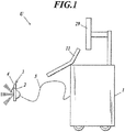
- FIG. 1 illustrates the whole appearance of an ultrasound image diagnostic apparatus U according to the embodiment.
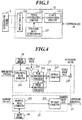
- FIG. 2 is a block diagram illustrating the functional configuration of the ultrasound image diagnostic apparatus U.
- FIG. 3 is a block diagram illustrating the functional configuration of a transmitter 12.
- FIG. 4 is a block diagram illustrating the functional configurations of a puncture needle emphasizing signal processor 23 and a harmonic signal processor 25.
- the ultrasound image diagnostic apparatus U includes an ultrasound image diagnostic apparatus main unit 1, an ultrasound probe 2 connected to the ultrasound image diagnostic apparatus main unit 1 with a cable 5 or by wireless communication means, a puncture needle 3, and an attachment 4 mounted to the ultrasound probe 2.
- the ultrasound probe 2 transmits ultrasound waves (transmitting ultrasound waves) to a subject (not shown), such as a living body, and receives the ultrasound waves (echoes) reflected from the subject.
- the ultrasound image diagnostic apparatus main unit 1 supplies the ultrasound probe 2 with electrical driving signals to cause the ultrasound probe 2 to transmit ultrasound waves to the subject, and generates an ultrasound image of the interior of the subject on the basis of electrical response signals, which are generated by the ultrasound probe 2 in response to reception of the echoes from the subject.
- the ultrasound probe 2 includes a stack of, for example, a backing layer, a piezoelectric layer, an acoustic matching layer, and an acoustic lens.
- the piezoelectric layer is equipped with oscillators (not shown) having piezoelectric elements.
- the oscillators are disposed, for example, in a one-dimensional array along the orientation direction.
- the ultrasound probe 2 includes 192 oscillators, for example.
- the oscillators may be disposed in a two-dimensional array. The number of the oscillators may be appropriately varied.
- the ultrasound probe 2 is an electronic scanning probe of a linear scanning type in the embodiment, the ultrasound probe 2 may be a mechanical or electronic scanning probe of a linear scanning, sector scanning, or convex scanning type.
- the puncture needle 3 is elongated and hollow, and is configured to be inserted into a subject at an angle defined by the attachment 4.
- the puncture needle 3 may be replaced with one having any appropriate thickness, length, and tip shape depending on a target (specimen) to be sampled or the type and volume of an agent to be injected.
- the attachment 4 retains the puncture needle 3 in the determined orientation (direction).
- the attachment 4 is mounted to a side of the ultrasound probe 2 and can appropriately change the orientation of the puncture needle 3 depending on a desired angle of the puncture needle 3 relative to the subject.
- the attachment 4 can shift the puncture needle 3 in the puncture direction and also insert the puncture needle 3 while rotating (spinning) the puncture needle 3 about its central axis.
- the ultrasound probe 2 may be directly provided with a guide for retaining the puncture needle 3 in the puncture direction, in place of the attachment 4.
- the ultrasound image diagnostic apparatus main unit 1 includes an input operation unit 11 (functioning as a first input unit or a second input unit), a display 29, a transceiver A, a line adding unit B, a line-signal processor C, a frame-signal processor D, a digital scan converter (DSC) 28 (functioning as a display controller), and a controller 30.
- an input operation unit 11 functioning as a first input unit or a second input unit
- a display 29 includes a display 29, a transceiver A, a line adding unit B, a line-signal processor C, a frame-signal processor D, a digital scan converter (DSC) 28 (functioning as a display controller), and a controller 30.
- DSC digital scan converter
- the transceiver A includes a transmitter 12 and a receiver 13.
- the line adding unit B is provided with a line memory 14 (functioning as a memory), an adder 15, and a switch 16.
- the line-signal processor C includes a dynamic filter 17, a factor memory 18, a detecting processor 19, a log compressing processor 20, and a factor memory 21.
- the frame-signal processor D is provided with a switch 22, a puncture needle emphasizing signal processor 23, frame memories 24 and 26, a harmonic signal processor 25, and a synthesizer 27.
- the input operation unit 11 includes a push button switch, a keyboard, a mouse, a trackball, or any combination thereof.
- the input operation unit 11 converts an operational input by a user (an inspector, such as a technician or doctor) into operation signals and inputs the signals to the ultrasound image diagnostic apparatus main unit 1.
- the input operation unit 11 receives input of a display depth (i.e., the depth of a target site from the surface of the subject) and a synthesizing factor (i.e., a factor for needle image data on the puncture needle 3 in the synthesis of the needle image data and harmonic image data).
- the transmitter 12 is a circuit that supplies the ultrasound probe 2 with electrical driving signals via the cable 5 to cause the ultrasound probe 2 to generate transmitting ultrasound waves, under the control of the controller 30.
- the transmitter 12 repeats alternating output of pulse driving signals corresponding to positive fundamental waves for a single line of an ultrasound image and pulse driving signals corresponding to negative fundamental waves (generated by polarity inversion of the positive fundamental waves) for the same line, on the basis of the pulse inversion technique of THI.
- the transmitter 12 thus outputs pulse signals corresponding to positive and negative fundamental waves for multiple lines.
- the transmitter 12 includes, for example, a clock generating circuit 121, a pulse generating circuit 122, a voltage-duty determiner 123, and a delay circuit 124.
- the clock generating circuit 121 generates clock signals for determining the transmission timing and frequency of driving signals.
- the pulse generating circuit 122 generates pulse signals (driving signals) in predetermined cycles.
- the pulse generating circuit 122 can generate rectangular pulse signals, for example, through switching their voltage among determined five values (+HV/+MV/0/-MV/-HV) and determining the duty ratio.
- the pulse signals corresponding to the positive and negative fundamental waves have the same amplitude in the embodiment, this feature should not be construed to limit the invention.
- the voltage of the pulse signals is switched among five values in the embodiment, the number of the values may be any appropriate number (preferably five or smaller), and the number is not limited to five. This configuration can improve the flexibility of control over frequency components at low costs and can enhance the resolution of transmitting ultrasound waves.
- the voltage-duty determiner 123 determines the voltage and duty ratio of pulse signals to be output from the pulse generating circuit 122.
- the pulse generating circuit 122 outputs pulse signals shaped in accordance with the voltage and duty ratio determined by the voltage-duty determiner 123.
- the voltage and duty ratio may be changed by, for example, input from the input operation unit 11.
- the receiver 13 is a circuit that receives electrical response signals from the ultrasound probe 2 via the cable 5 or wireless communication means, under the control of the controller 30.
- the receiver 13 includes, for example, an amplifier, an analog-digital conversion circuit, and a phasing adding circuit.
- the amplifier is a circuit that amplifies the response signals by a predetermined gain for the respective paths from the oscillators.
- the analog-digital conversion circuit performs analog-digital conversion (A/D conversion) to the amplified signals.
- the phasing adding circuit phases the digitized signals by adding the delay times for the respective paths from the oscillators to the signals, and then adds up the phased signals to generate sound ray data.
- the line adding unit B is equipped with the line memory 14, the adder 15, and the switch 16.
- the line memory 14 stores sound ray data on the pulse signals corresponding to positive fundamental waves for a single line from the receiver 13.
- the adder 15 reads the sound ray data from the line memory 14, and adds the read sound ray data to sound ray data on the pulse signals corresponding to negative fundamental waves for the same line from the receiver 13 (i.e., sound ray data on the pulse signals corresponding to negative fundamental waves output from the transmitter 12 subsequently to the pulse signals corresponding to positive fundamental waves indicated by the read sound ray data), under the control of the controller 30.
- This addition by the adder 15 offsets the positive and negative fundamental components, allowing extraction of sound ray data on harmonic components synthesized mainly of second harmonic waves.
- the switch 16 varies the path of sound ray data output to the line-signal processor C (dynamic filter 17) for each line, under the control of the controller 30.
- the switch 16 in response to input of the sound ray data on the pulse signals corresponding to positive fundamental waves for a single line to the line adding unit B, the switch 16 connects the path to the receiver 13 so that the input sound ray data is directly output; whereas in response to input of the sound ray data on the pulse signals corresponding to negative fundamental waves for the same line to the line adding unit B, the switch 16 connects the path to the adder 15 so that the sound ray data on harmonic components generated by the adder 15 is output.
- the line adding unit B thus requires only two cycles of transception of ultrasound waves to output sound ray data on fundamental and harmonic components, achieving a higher frame rate than that of a traditional apparatus requiring three cycles.
- the dynamic filter 17 is a digital filter for filtering the sound ray data output from the line adding unit B (switch 16) under the control of the controller 30.
- the dynamic filter 17 has multiple taps, and the filtering characteristics can be varied through adjustment of the factors for the taps.
- the factor memory 18 stores the tap factor for fundamental images (needle images for detecting the puncture needle 3) and the tap factor for harmonic images.
- the dynamic filter 17 In response to input of the sound ray data on the pulse signals corresponding to positive fundamental waves for a single line from the line adding unit B, the dynamic filter 17 reads the tap factor for fundamental images from the factor memory 18 and applies the factor to the taps, to filter and transmit the fundamental components of the input sound ray data. In response to input of the sound ray data on the harmonic components for the same line from the line adding unit B, the dynamic filter 17 reads the factor for harmonic images from the factor memory 18 and applies the tap factor to the taps, to filter and transmit the second harmonic components of the input sound ray data.
- the detecting processor 19 extracts envelope data through envelope detection of the sound ray data from the dynamic filter 17, under the control of the controller 30.
- the log compressing processor 20 adjusts the gain of the envelope data output from the detecting processor 19 through log compression, and outputs the resulting data as line data indicating brightness values of the image, under the control of the controller 30.
- the factor memory 21 stores the log-compression factor for fundamental images for narrowing the dynamic range and the log-compression factor for harmonic images for broadening the dynamic range.
- the log compressing processor 20 In response to input of the envelope data on the pulse signals corresponding to positive fundamental waves for a single line from the detecting processor 19, the log compressing processor 20 reads the log-compression factor for fundamental images from the factor memory 21, narrows the dynamic range of the input envelope data through log compression depending on the read factor, and then outputs the resulting data as fundamental line data. In response to input of the envelope data on the harmonic components for the same line from the detecting processor 19, the log compressing processor 20 reads the log-compression factor for harmonic images from the factor memory 21, broadens the dynamic range of the input envelope data through log compression depending on the read factor, and then outputs the resulting data as harmonic line data.
- the switch 22 varies the path of image data from the line-signal processor C (log compressing processor 20) for each line, under the control of the controller 30.
- the switch 22 in response to input of the fundamental line data on the pulse signals corresponding to positive fundamental waves for a single line, the switch 22 connects the path to the puncture needle emphasizing signal processor 23 so that it receives the fundamental line data; whereas in response to input of the harmonic line data on the harmonic components for the same line, the switch 22 connects the path to the harmonic signal processor 25 so that it receives the harmonic line data.
- the puncture needle emphasizing signal processor 23 infers the background of the input image on the basis of the image data stored in the frame memory 24, and extracts the difference between the background and the input image to emphasize the puncture needle.
- the DSC 28 converts synthesized image data, which is received from the frame-signal processor D (synthesizer 27), into image signals for the display 29 through processes, such as coordinate conversion, and outputs the image signals, under the control of the controller 30.
- Examples of the display 29 include a liquid crystal display (LCD), a cathode-ray tube (CRT) display, an organic electroluminescent (EL) display, an inorganic EL display, and a plasma display.
- the display 29 displays an ultrasound image on its screen in accordance with the image signals output from the DSC 28.
- the controller 30 includes, for example, a central processing unit (CPU), a read only memory (ROM), and a random access memory (RAM).
- the controller 30 reads various processing programs, such as a system program, from the ROM and loads the programs in the RAM, to comprehensively control the operations of the individual components of the ultrasound image diagnostic apparatus U under the instructions of the programs.
- the ROM includes a nonvolatile memory, such as a semiconductor memory.
- the ROM stores a system program for the ultrasound image diagnostic apparatus U, various processing programs executable under the system program, and various pieces of data. These programs are stored in the form of computer-readable program codes, and the CPU sequentially executes operations under the instructions corresponding to the program codes.
- the RAM defines a work area for temporarily storing various programs to be executed by the CPU and data related to the programs.
- FIG. 2 illustrates only some of the control lines from the controller 30 to the individual components.
- Hardware circuits such as integrated circuits, may have some or all of the functions of the individual functional blocks, i.e., the transceiver A, the line adding unit B, the line-signal processor C, the frame-signal processor D, and the DSC 28 of the ultrasound image diagnostic apparatus U.
- the integrated circuits include large scale integration (LSI) circuits.
- the LSI circuit is also referred to as IC, system LSI circuit, super LSI circuit, or ultra LSI circuit depending on its degree of integration.
- the integration may be achieved by any dedicated circuit, general-purpose processor, field programmable gate array (FPGA), or reconfigurable processor, which has reconfigurable connection and setting of circuit cells in the LSI, other than the LSI.
- software may have part or all of the functions of the individual functional blocks. In this case, the software is stored in one or more recording media (e.g., ROMs), optical disks, or hard disks, and is executed by a processor.
- the puncture needle emphasizing signal processor 23 includes a fundamental image generator 231, branches 232 and 233, a weak smoothing processor 234 (functioning as a first smoothing processor), a strong smoothing processor 235 (functioning as a second smoothing processor), a subtracter 236, a contrast corrector 237 (functioning as a first contrast corrector), and a multiplier 238.
- the harmonic signal processor 25 is provided with a harmonic image generator 251 and a contrast corrector 252 (functioning as a second contrast corrector).
- the fundamental image generator 231 sequentially stores pieces of fundamental line data, which is received from the switch 22, into the frame memory 24, under the control of the controller 30. After storing a single frame of fundamental line data, the fundamental image generator 231 reads the single frame of fundamental line data from the frame memory 24 and outputs the single frame of fundamental image data.
- the frame memory 24 can store at least one frame of fundamental line data.
- the branch 232 outputs the fundamental image data received from the fundamental image generator 231 to the weak smoothing processor 234 and the strong smoothing processor 235.
- the branch 233 outputs the display depth, which is input by the user from the input operation unit 11 via the controller 30, to the weak smoothing processor 234 and the strong smoothing processor 235.
- the weak smoothing processor 234 performs smoothing with relatively low intensity to the fundamental image data from the branch 232 depending on the display depth from the branch 233, and then outputs the smoothed data.
- the strong smoothing processor 235 performs smoothing with relatively high intensity to the fundamental image data from the branch 232 depending on the display depth from the branch 233, and then outputs the smoothed data.
- the smoothing by the weak smoothing processor 234 is weaker than that by the strong smoothing processor 235. In other words, the smoothing by the strong smoothing processor 235 is stronger than that by the weak smoothing processor 234.
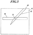
- FIG. 5 illustrates a positional relationship between a detection area for smoothing and a smoothing target in a fundamental image 40.
- FIG. 5 illustrates an ultrasound image, at the top of which the elements of the ultrasound probe 2 are disposed in the right and left direction, and which includes a detection area 50 elongated in the horizontal direction.
- the vertical direction corresponds to the direction orthogonal to the array of the elements in the ultrasound probe 2 (i.e., the up and down direction in FIG. 5 ).
- the fundamental image 40 is an ultrasound image (B mode image) based on fundamental image data, and has a subject area 41 representing the subject and a needle area 42 representing the puncture needle 3 inserted in the subject, as illustrated in FIG. 5 .
- the upper side of the subject area 41 i.e., the top edge of the fundamental image 40 depicts the surface of the subject.
- the weak smoothing processor 234 and the strong smoothing processor 235 perform smoothing based on the detection area 50 around a smoothing target pixel 51 among all the pixels of the fundamental image 40, to generate the smoothed fundamental image data, under the control of the controller 30.
- the smoothing based on averaging is performed in a rectangular area, like the detection area 50 in FIG. 5 .
- the detection area 50 in an image in the actual dimensions is a rectangle having a longer horizontal width than the vertical length, and includes the smoothing target pixel 51 near the center.
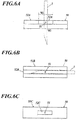
- the detection area 50 is composed of a relatively weak smoothing region 52A, which has a rectangular shape having a width W1 and is disposed in the substantial center in the horizontal direction of the detection area 50, and a relatively strong smoothing region 53A, which has a rectangular shape having a width W2 and ranges over the entire detection area 50.
- the needle area representing the puncture needle 3 in the fundamental image is emphasized for detection.
- the width of the needle area in the fundamental image decreases as the display depth increases.
- the sizes of the weak smoothing region 52A and the strong smoothing region 53A are designed to decrease without variations in their shapes as the display depth increases. The same holds true for weak smoothing regions 52B and 52C and strong smoothing regions 53B and 53C (described below).
- the weak smoothing processor 234 performs weak smoothing that involves selection of a single smoothing target pixel 51 from the input fundamental image data, and calculation of the average value of the weak smoothing region 52A around the smoothing target pixel 51.
- the weak smoothing processor 234 repeats the selection of an unselected pixel from the input fundamental image data and the averaging operation, to generate weakly-smoothed fundamental image data.
- the strong smoothing processor 235 performs strong smoothing that involves selection of a single smoothing target pixel 51 from the input fundamental image data, and calculation of the average value of the strong smoothing region 53A around the smoothing target pixel 51.
- the strong smoothing processor 235 repeats the selection of an unselected pixel from the input fundamental image data and the averaging operation, to generate strongly-smoothed fundamental image data.
- the weak smoothing by the weak smoothing processor 234 can remove small noises, such as speckles, from the fundamental image.
- the strong smoothing by the strong smoothing processor 235 can estimate the brightness values of the background of the fundamental image, other than the needle area.
- the subtracter 236 subtracts the strongly-smoothed fundamental image data received from the strong smoothing processor 235 from the weakly-smoothed fundamental image data received from the weak smoothing processor 234, to generate and output the fundamental image data (needle image data) including the emphasized puncture needle 3, under the control of the controller 30.
- the subtraction by the subtracter 236 can extract frequency components corresponding to the thickness of the puncture needle 3 from the fundamental image data.
- the weak smoothing processor 234 and the strong smoothing processor 235 use the detection area 50 in FIG. 6A , and the subtraction by the subtracter 236 allows the needle area that passes through the weak smoothing region 52A to be emphasized (to have large differences after subtraction) in the detection area 50.
- the puncture needle 3 inserted vertically or obliquely is emphasized in the fundamental image, whereas the puncture needle 3 inserted horizontally and tissues of the subject that extend horizontally are not emphasized in the fundamental image.
- the weak smoothing processor 234 and the strong smoothing processor 235 may use the detection area 50 composed of a weak smoothing region 52B and a strong smoothing region 53B, as illustrated in FIG. 6B .
- the detection area 50 in FIG. 6B includes the smoothing target pixel 51 near the center, and is composed of the weak smoothing region 52B, which has a rectangular shape and occupies only the central part in the vertical direction of the detection area 50, and the strong smoothing region 53B, which has a rectangular shape and ranges over the entire detection area 50.
- the weak smoothing processor 234 and the strong smoothing processor 235 use the detection area 50 in FIG. 6B , and the subtraction by the subtracter 236 allows the needle area that passes through the weak smoothing region 52B to be emphasized in the detection area 50.
- the puncture needle 3 inserted horizontally or obliquely is emphasized in the fundamental image. It should be noted that tissues of the subject that extend horizontally are also emphasized, whereas the puncture needle 3 inserted vertically and tissues of the subject that extend vertically are not emphasized.
- the weak smoothing processor 234 and the strong smoothing processor 235 may use the detection area 50 composed of a weak smoothing region 52C and a strong smoothing region 53C, as illustrated in FIG. 6C .
- the detection area 50 includes the smoothing target pixel 51 near the center, and is composed of the weak smoothing region 52C, which has a rectangular shape and occupies only the central part in the horizontal and vertical directions of the detection area 50, and the strong smoothing region 53C, which has a rectangular shape and ranges over the entire detection area 50.
- the weak smoothing processor 234 and the strong smoothing processor 235 use the detection area 50 in FIG. 6C , and the subtraction by the subtracter 236 allows the needle area that passes through the weak smoothing region 52C to be emphasized in the detection area 50.
- the puncture needle 3 inserted horizontally, vertically, or obliquely is emphasized in the fundamental image. It should be noted that tissues of the subject that extend horizontally or vertically are also emphasized.
- the weak smoothing processor 234 smooths a smaller region with lower intensity than the strong smoothing processor 235.
- the strong smoothing processor 235 smooths a larger region with higher intensity than the weak smoothing processor 234.
- the image may be smoothed by Gaussian smoothing.
- Gaussian smoothing a larger variance of Gaussian smoothing provides smoothing with larger intensity.
- the Gaussian smoothing uses the variance in the horizontal direction among the variances in the horizontal and vertical directions.
- the contrast corrector 237 provides the needle image data received from the subtracter 236 with contrast between a needle area and a non-needle area through, for example, contrast correction involving gradation correction based on a sigmoid function, under the control of the controller 30.
- the multiplier 238 multiplies the brightness values of the respective pixels of the needle image data after contrast correction received from the contrast corrector 237 by the synthesizing factor, which is input by the user from the input operation unit 11 via the controller 30, to generate and output the needle image data multiplied by the synthesizing factor, under the control of the controller 30.
- the harmonic image generator 251 stores pieces of harmonic line data, which is received from the switch 22, into the frame memory 26, under the control of the controller 30. After storing a single frame of harmonic line data, the harmonic image generator 251 reads the single frame of harmonic line data from the frame memory 26 and outputs the single frame of harmonic image data.
- the frame memory 26 can store at least one frame of harmonic line data.
- the contrast corrector 252 performs contrast correction for harmonic images, which involves gradation correction, to the harmonic image data received from the harmonic image generator 251, and outputs the resulting data, under the control of the controller 30.
- the contrast correction for harmonic images lowers the brightness values of the harmonic image or darkens the image, making the needle image (especially, the needle area) outstanding against the harmonic image.
- the synthesizer 27 adds the brightness values of the respective pixels of the needle image data received from the puncture needle emphasizing signal processor 23 (multiplier 238) to the brightness values of the respective pixels of the harmonic image data received from the harmonic signal processor 25 (contrast corrector 252) to combine the image data together, and then outputs the synthesized image data, under the control of the controller 30.
- FIG. 7 illustrates example composition of ultrasound images.
- the ultrasound image diagnostic apparatus U starts ultrasound image diagnosis in response to input of a display depth and a synthesizing factor by a user and appropriate inserting of the puncture needle 3 into a subject.
- the transceiver A repeats alternating generation of driving signals corresponding to positive fundamental waves and driving signals corresponding to negative fundamental waves for each line on the basis of THI. These driving signals cause the ultrasound probe 2 to transmit and receive ultrasound waves, providing sound ray data on response signals corresponding to the ultrasound waves.
- the sound ray data on the positive pulse signals from the transceiver A is directly output from the line adding unit B and is also stored into the line memory 14.
- the line-signal processor C converts the sound ray data on the positive pulse signals received from the line adding unit B into fundamental line data through the processes for fundamental images involving filtering, envelope detection, and log compression.
- the frame-signal processor D then stores the fundamental line data received from the line-signal processor C into the frame memory 24.
- the line adding unit B adds the sound ray data on the negative pulse signals, which is subsequently output from the transceiver A, to the sound ray data on the positive pulse signals stored in the line memory 14, and then outputs the resulting sound ray data.
- the line-signal processor C converts the sound ray data, which has harmonic components, received from the line adding unit B into harmonic line data through the processes for harmonic images involving filtering, envelope detection, and log compression.
- the frame-signal processor D then stores the harmonic line data received from the line-signal processor C into the frame memory 26.
- the puncture needle emphasizing signal processor 23 reads the single frame of fundamental image data, generates needle image data from the fundamental image data, and then multiplies the needle image data by the synthesizing factor. Also, after storing a single frame of harmonic line data in the frame memory 26, the harmonic signal processor 25 reads the single frame of harmonic line data and performs contrast correction for harmonic images to the read data.
- the frame-signal processor D (synthesizer 27) then generates synthesized image data from the single frame of needle image data and the single frame of harmonic image data.
- the synthesized image is transmitted through the DSC 28, and then displayed on the display 29.
- fundamental image data on a fundamental image 60 is read from the frame memory 24, and is converted into needle image data on a needle image 70 by the weak smoothing processor 234 and the strong smoothing processor 235, which perform smoothing based on the detection area 50, and the subtracter 236.
- harmonic image data on a harmonic image 80 is read from the frame memory 26.
- the needle image 70 the needle area representing the puncture needle 3 inserted obliquely has increased brightness values for emphasis, whereas the background other than the needle area has decreased brightness values, in comparison to the fundamental image 60.
- the muscular tissue, which extends horizontally in the lower part of the fundamental image 60, is not emphasized in the needle image 70.
- the harmonic image 80 has a higher spatial resolution than the fundamental image 60.
- the needle image data on the needle image 70 is multiplied by a certain synthesizing factor, and is combined with the harmonic image data on the harmonic image 80 by the synthesizer 27, yielding synthesized image data on a synthesized image 90.
- the needle area has increased brightness values for emphasis as in the needle image 70, whereas the background other than the needle area has a higher spatial resolution as in the harmonic image 80.
- the ultrasound image diagnostic apparatus U for capturing an image of the subject into which the puncture needle 3 is inserted, includes: the ultrasound probe 2 to transmit ultrasound waves to the subject in response to received pulse signals and output response signals in response to received echoes from the subject; the transmitter 12 to repeat alternating supply of positive pulse signals and negative pulse signals to the ultrasound probe 2, the negative pulse signals being generated by polarity inversion of the positive pulse signals; and the receiver 13 to receive the response signals from the ultrasound probe 2 and generate sound ray data.
- the ultrasound image diagnostic apparatus U includes the line memory 14 to store the first sound ray data corresponding to the positive pulse signal; the adder 15 to generate harmonic line data through addition of the stored first sound ray data and the second sound ray data corresponding to the negative pulse signal; and the line-signal processor C to generate fundamental line data from the generated first sound ray data and generate harmonic line data from the harmonic sound ray data.
- the ultrasound image diagnostic apparatus U includes the fundamental image generator 231 to generate fundamental image data from the generated fundamental line data; a needle image generator to generate needle image data from the generated fundamental image data, the needle image data including an emphasized needle area corresponding to the puncture needle 3; the harmonic image generator 251 to generate harmonic image data from the generated harmonic line data; the synthesizer 27 to generate synthesized image data through combining the generated needle image data and the generated harmonic image data; and the controller 30 to control the display 29 to display the generated synthesized image data.
- This apparatus can provide synthesized image data on the ultrasound image that clearly captures the puncture needle in the needle area based on the needle image data, and has high spatial resolution on the basis of the harmonic image data.
- the apparatus can obtain a single line of line data through only two cycles of transmission of positive and negative pulse signals, preventing decrease of frame rate.
- the ultrasound image diagnostic apparatus U further includes the switch 16 to output one of the generated first sound ray data and the harmonic sound ray data, which is generated through addition of the first sound ray data stored in the line memory 14 and the second sound ray data corresponding to the second pulse signals.
- This apparatus can switch the output between the harmonic sound ray data and the first sound ray data without delay, and requires only two cycles of transception of ultrasound waves to output the sound ray data on fundamental and harmonic components, achieving a higher frame rate than that of a traditional apparatus requiring three cycles.
- the line-signal processor C generates the fundamental line data through a process for fundamental images (filtering and log compression) on the generated first sound ray data, and generates the harmonic line data through a process for harmonic images (filtering and log compression) on the harmonic sound ray data.
- This apparatus can generate appropriate fundamental line data after the process for fundamental images and appropriate harmonic line data after the process for harmonic images. Furthermore, the apparatus has a simplified configuration because the fundamental line data and the harmonic line data share some of their paths.
- the needle image generator includes: the weak smoothing processor 234 to generate first smoothed image data through smoothing of the generated fundamental image data; the strong smoothing processor 235 to generate second smoothed image data through smoothing of the fundamental image data with higher intensity than the intensity of the smoothing for the first smoothed image data; and the subtracter 236 to calculate differences of the second smoothed image data from the first smoothed image data.
- This apparatus can further emphasize the needle area representing the puncture needle 3 in the needle image data.
- Patent Literature 2 for capturing an image of a puncture needle requires the emphasis of the puncture needle that is inserted obliquely from the surface of the subject.
- the strong smoothing processor 235 performs smoothing with higher intensity in the horizontal direction than in the vertical direction on the fundamental image data in the actual dimensions.
- the weak smoothing processor 234 and the strong smoothing processor 235 determine a first smoothing region for generation of the first smoothed image data and a second smoothing region for generation of the second smoothed image data.
- the first smoothing region is disposed in the substantial center of the second smoothing region, and the first smoothing region includes a smoothing target pixel in the substantial center.
- the first smoothing region is disposed in the substantial center of the second smoothing region in the horizontal or vertical direction of the fundamental image data.
- This apparatus can further emphasize the needle area representing the puncture needle 3 that is inserted at least vertically or obliquely (alternatively, horizontally or obliquely) from the surface of the subject, without emphasizing tissues that extend horizontally or vertically from the surface, in the needle image data.
- the ultrasound image diagnostic apparatus U further includes the input operation unit 11 to receive input of a display depth.
- the weak smoothing processor 234 generates the first smoothed image data with a smaller first smoothing region as the display depth increases, and the strong smoothing processor 235 generates the second smoothed image data with a smaller second smoothing region as the display depth increases.
- This apparatus can maintain the appropriate size (width) of the needle area in the fundamental image without becoming narrow even when the display depth increases.
- the ultrasound image diagnostic apparatus U further includes the contrast corrector 237 that performs first contrast correction involving gradation correction to the needle image data, to provide the data with contrast between the needle area and the non-needle area.
- the resulting needle image thus has contrast between the needle area and the non-needle area.
- the ultrasound image diagnostic apparatus U further includes the contrast corrector 252 that performs second contrast correction involving gradation correction to the generated harmonic image data, to lower the brightness values of the data.
- the resulting harmonic image thus has decreased brightness values.
- the synthesizer 27 generates the synthesized image data through combining the needle image data after the first contrast correction and the harmonic image data after the second contrast correction.
- the resulting synthesized image thus has the needle area that is brighter for emphasis in comparison to the background other than the needle area.
- the ultrasound image diagnostic apparatus U further includes: the input operation unit 11 to receive input of a synthesizing factor for the needle image data; and the multiplier 238 to multiply the brightness values of the generated needle image data by the synthesizing factor.
- the synthesizer 27 generates the synthesized image data through combining the needle image data multiplied by the synthesizing factor and the generated harmonic image data. The user can thus apply any synthesizing factor to the needle image relative to the harmonic image.
- the apparatus repeats alternating generation of pulse driving signals corresponding to positive fundamental waves and pulse driving signals corresponding to negative fundamental waves, which are inverted from the positive fundamental waves, and generates needle image data on the basis of the response signals associated with the pulse driving signals corresponding to positive fundamental waves in the embodiment; this configuration should not be construed to limit the invention.
- the apparatus may repeat alternating generation of pulse driving signals corresponding to negative fundamental waves and pulse driving signals corresponding to positive fundamental waves, which are inverted from the negative fundamental waves, and generate needle image data on the basis of the response signals associated with the pulse driving signals corresponding to negative fundamental waves.
- the puncture needle emphasizing signal processor 23 generates needle image data from the fundamental line data based on the response signals associated with the pulse signals corresponding to (positive) fundamental waves in the embodiment, this configuration should not be construed to limit the invention.
- the harmonic image generator 251 may generate harmonic image data from the fundamental line data based on the response signals associated with the pulse signals corresponding to positive and negative fundamental waves, and store the harmonic image data into the frame memory 26.
- the puncture needle emphasizing signal processor 23 except for the fundamental image generator 231 may generate needle image data from the generated harmonic image data, and generate synthesized image data through combining the needle image data and the harmonic image data that is stored and subject to gradation correction by the contrast corrector 252 with any input synthesizing factor.
- This modification does not need the switch 22, the fundamental image generator 231, and the frame memory 24, simplifying the configuration of the ultrasound image diagnostic apparatus U.
- This modified apparatus uses no fundamental line data, for example, so that the line adding unit B outputs sound ray data on the harmonic components without outputting sound ray data on the pulse signals corresponding to fundamental waves, whereas the line-signal processor C performs various processes to the sound ray data on the harmonic components and outputs harmonic line data.
- the puncture needle emphasizing signal processor may be replaced with a puncture needle emphasizing signal processor 300 illustrated in FIG. 8.
- FIG. 8 is a block diagram illustrating the functional configuration of the puncture needle emphasizing signal processor 300.
- the puncture needle emphasizing signal processor 300 is provided with an image generator 301, in place of the fundamental image generator 231 in the puncture needle emphasizing signal processor 23 in FIG. 4 .
- the image generator 301 receives line data on an ultrasound image from the line-signal processor.
- the image generator 301 generates a single frame of image data from the received line data, and outputs emphasized needle image data, like the puncture needle emphasizing signal processor 23.
- the ultrasound image diagnostic apparatus can be applied to ultrasonography using a puncture needle.
Description
- The present invention relates to an ultrasound image diagnostic apparatus.
- Traditional ultrasound image diagnostic apparatuses inspect the interiors of subjects through emitting ultrasound waves into the subjects to receive ultrasound waves (echoes) reflected from the subjects, and conducting predetermined processes to signal data on the received echoes. Such ultrasound image diagnostic apparatuses are used for various purposes, such as medical tests and treatments and inspection of the internal structures of buildings.
- The ultrasound image diagnostic apparatuses can generate images having good contrast from the harmonic components (e.g., frequencies 2f0 and 3f0) of transmitting signals relative to their fundamental components (frequency f0). This technique is called tissue harmonic imaging (THI).
- These harmonic components are mainly caused by the non-linear distortion of ultrasound waves during propagation in a subject. In specific, incident ultrasound waves in a living body are distorted by the non-linear response of tissues during propagation in the tissues, resulting in increased harmonic components. The response signals corresponding to the ultrasound waves thus include, for example, components of frequencies 2f0 and 3f0 (two and three times the frequency f0 of fundamental waves).
- The harmonic components in the tissue harmonic imaging can be extracted by a known method, such as a filtering technique or pulse inversion technique.
- In the filtering technique, a band-pass filter having a center frequency of 2f0, for example, extracts 2f0 harmonic components from response signals. In the pulse inversion technique, the apparatuses transmit first and second pulse signals that are polarity-inverted or time-inverted at a predetermined time interval, and combine their response signals to offset the fundamental components, thereby emphasizing the second harmonic components.
- A typical ultrasound image diagnostic apparatus based on the pulse inversion technique generates fundamental image signals from first echoes after the first transception (transmission and reception) of fundamental ultrasound waves, generates harmonic image signals through addition of second echoes after the second transception of inverted fundamental ultrasound waves to the first echoes, and then combines the fundamental image signals with the harmonic image signals, which are weighted depending on the depth for each line (scanning line) (refer to Patent Literature 1). The synthesized image is made of a harmonic image in a shallow portion and a fundamental image in a deep portion, and has few artifacts and sufficient sensitivity even in the deep portion.
- The use of the ultrasound image diagnostic apparatuses is not limited to ultrasound image display of a subject based on the processed data on received echoes. The ultrasound image diagnostic apparatuses are also used to identify and visualize the position of a puncture needle relative to a specific portion (target) in a subject during the inserting of the puncture needle into the target for sampling the target, discharging water from the target, or injecting or indwelling an agent or marker into the target. Such ultrasound image can achieve rapid, certain, and ready treatment for the target in the subject.
- The pulse inversion technique can be applied to the imaging of a subject using such a puncture needle. For example, a typical ultrasound image diagnostic apparatus repeats the first transception of positive ultrasound waves, the second transception of negative ultrasound waves (inverted from the positive ultrasound waves), and the third transception of negative ultrasound waves; generates a normal mode image through combining the first echoes and the second echoes; and generates a puncture mode image through combining the first echoes and the third echoes (refer to Patent Literature 2). The normal mode image is based on a relatively low pulse repetition frequency (PRF) and thus has reduced motion artifacts caused by motions of the living body, whereas the puncture mode image is based on a relatively high PRF and can thus capture motion artifacts caused by motions of the puncture needle well.
-
- [Patent Literature 1] Japanese Unexamined Patent Application Publication No.
2012-96095 - [Patent Literature 2] Japanese Unexamined Patent Application Publication No.
2006-150069 -
WO 2011/154782 discloses an invasive medical device which includes a fluid path of microbubbles which is imaged by ultrasound during use of the device. The fluid path extends through the device, preferably to the distal end of the device, so that the diffuse reflection of ultrasound from the microbubbles can be received to image the location of the device. The fluid path can be open, terminating at the tip of the device, or can be a closed path of a circulating microbubble fluid used for imaging and/or cooling. -
EP 1281368 discloses a method and apparatus for ultrasound imaging of a biopsy needle or the like during an ultrasound imaging examination of a body of biologic tissues, including alternately performing one or more imaging scans with ultrasound transmit and receive parameters which are adapted for optimized imaging and visualization of the needle and one or more imaging scans with ultrasound transmit and receive parameters adapted for optimized imaging and visualization of a body comprising biological tissues or details thereof, in which the needle is inserted. The method includes the additional steps of injecting contrast agents in the region to be examined before imaging and setting ultrasound transmit and receive parameters adapted for optimized imaging and visualization of the body or details thereof, wherein the needle is inserted, so that these parameters are optimized for imaging fluid flows within the body. - Unfortunately, the ultrasound image diagnostic apparatus disclosed in Patent Literature 2 requires three cycles of transception (transmission and reception) of ultrasound waves to obtain a normal mode image and a puncture mode image. The obtained images thus have lower frame rates compared to those based on two cycles of transception.
- Furthermore, the ultrasound image diagnostic apparatus disclosed in Patent Literature 2 generates a puncture mode image from harmonic components extracted by the pulse inversion technique. The harmonic components form an ultrasound beam that is narrow not only in the long axis direction but also in the short axis direction (direction of slicing), and thus are advantageous in a brightness (B) mode image (normal mode image). Unfortunately, in a puncture mode image, such a narrow ultrasound beam often misses the puncture needle moving away from the plane of slicing and cannot readily capture the puncture needle.
- In addition, the ultrasound image diagnostic apparatus disclosed in Patent Literature 2 emphasizes tissues around the puncture needle in addition to motion artifacts caused by motions of the living body in a puncture mode image.
- An object of the present invention is to obtain an ultrasound image clearly capturing a puncture needle and having high spatial resolution. Another object is to prevent reduction of frame rate.
- In view of the above problems, according to the present invention, there is provided an ultrasound image diagnostic apparatus according to
claim 1. Optional features are recited in dependent claims. According to one configuration as described herein, there is provided an ultrasound image diagnostic apparatus for capturing an image of a subject into which a puncture needle is inserted, the apparatus including: - an ultrasound probe to transmit ultrasound waves to the subject in response to received pulse signals and output response signals in response to received echoes from the subject;
- a transmitter to repeat alternating supply of first pulse signals and second pulse signals to the ultrasound probe, the second pulse signals being generated by polarity inversion of the first pulse signals;
- a receiver to receive the response signals from the ultrasound probe and generate sound ray data;
- a memory to store first sound ray data corresponding to the first pulse signals;
- an adder to generate harmonic sound ray data through addition of the stored first sound ray data and second sound ray data corresponding to the second pulse signals;
- a line-signal processor to generate fundamental line data from the generated first sound ray data and generate harmonic line data from the generated harmonic sound ray data;
- a fundamental image generator to generate fundamental image data from the generated fundamental line data;
- a needle image generator to generate needle image data from the generated fundamental image data, the needle image data including an emphasized needle area corresponding to the puncture needle;
- a harmonic image generator to generate harmonic image data from the generated harmonic line data;
- a synthesizer to generate synthesized image data through combining the generated needle image data and the generated harmonic image data; and
- a display controller to control a display to display the generated synthesized image data.
- A second aspect of the ultrasound image diagnostic apparatus according to
aspect 1, further including a switch to output one of the harmonic sound ray data and the generated first sound ray data, the harmonic sound ray data being generated through addition of the stored first sound ray data and the second sound ray data corresponding to the second pulse signals. - A third aspect of the ultrasound image diagnostic apparatus according to
aspect 1 or 2, wherein the line-signal processor generates the fundamental line data through a process for fundamental images on the generated first sound ray data, and generates the harmonic line data through a process for harmonic images on the generated harmonic sound ray data. - A fourth aspect of the ultrasound image diagnostic apparatus according to any one of
aspects 1 to 3, wherein the needle image generator includes: - a first smoothing processor to generate first smoothed image data through smoothing of the generated fundamental image data;
- a second smoothing processor to generate second smoothed image data through smoothing of the fundamental image data with higher intensity than the intensity of the smoothing for the first smoothed image data; and
- a subtracter to calculate differences of the second smoothed image data from the first smoothed image data.
- A fifth aspect of the ultrasound image diagnostic apparatus according to aspect 4, wherein the second smoothing processor performs smoothing with higher intensity in a horizontal direction than in a vertical direction on the fundamental image data in the actual dimensions.
- A sixth aspect of the ultrasound image diagnostic apparatus according to aspect 4, wherein the needle image generator determines a first smoothing region for generation of the first smoothed image data and a second smoothing region for generation of the second smoothed image data, the first smoothing region being disposed in the substantial center of the second smoothing region, the first smoothing region including a smoothing target pixel in the substantial center.
- A seventh aspect of the ultrasound image diagnostic apparatus according to aspect 6, wherein the first smoothing region is disposed in the substantial center of the second smoothing region in the horizontal or vertical direction of the fundamental image data.
- An eighth aspect of the ultrasound image diagnostic apparatus according to aspect 6 or 7, further including a first input unit to receive input of a display depth, wherein
the first smoothing processor generates the first smoothed image data with a smaller first smoothing region as the display depth increases, and
the second smoothing processor generates the second smoothed image data with a smaller second smoothing region as the display depth increases. - A ninth aspect of the ultrasound image diagnostic apparatus according to any one of
aspects 1 to 8, further comprising a first contrast corrector to perform first contrast correction involving gradation correction to the generated needle image data. - A tenth aspect of the ultrasound image diagnostic apparatus according to any one of
aspects 1 to 9, further including a second contrast corrector to perform second contrast correction involving gradation correction to the generated harmonic image data. - An eleventh aspect of the ultrasound image diagnostic apparatus according to any one of
aspects 1 to 10, further including: - a second input unit to receive input of a synthesizing factor for the needle image data; and
- a multiplier to multiply brightness values of the generated needle image data by the input synthesizing factor, wherein
- the synthesizer generates the synthesized image data through combining the needle image data multiplied by the synthesizing factor and the generated harmonic image data.
- The invention can obtain an ultrasound image clearly capturing a puncture needle and having high spatial resolution. The invention can also prevent reduction of frame rate.
-
-
FIG. 1 illustrates the appearance of an ultrasound image diagnostic apparatus; -
FIG. 2 is a block diagram illustrating the schematic configuration of an ultrasound image diagnostic apparatus; -
FIG. 3 is a block diagram illustrating the functional configuration of a transmitter; -
FIG. 4 is a block diagram illustrating the functional configurations of a puncture needle emphasizing signal processor according to a first embodiment and a harmonic signal processor; -
FIG. 5 illustrates a detection area for smoothing in a fundamental image; -
FIG. 6A illustrates a first example of smoothing regions; -
FIG. 6B illustrates a second example of smoothing regions; -
FIG. 6C illustrates a third example of smoothing regions; -
FIG. 7 illustrates example composition of ultrasound images; and -
FIG. 8 is a block diagram illustrating the functional configuration of a puncture needle emphasizing signal processor according to a second embodiment. - Embodiments of the invention will now be described in detail with reference to the accompanying drawings. The illustrated examples should not be construed to limit the invention.
- The configuration of an apparatus according to the present embodiment will now be described with reference to
FIGS. 1 to 6C .FIG. 1 illustrates the whole appearance of an ultrasound image diagnostic apparatus U according to the embodiment.FIG. 2 is a block diagram illustrating the functional configuration of the ultrasound image diagnostic apparatus U.FIG. 3 is a block diagram illustrating the functional configuration of atransmitter 12.FIG. 4 is a block diagram illustrating the functional configurations of a puncture needle emphasizingsignal processor 23 and aharmonic signal processor 25. - With reference to
FIG. 1 , the ultrasound image diagnostic apparatus U according to the present embodiment includes an ultrasound image diagnostic apparatusmain unit 1, an ultrasound probe 2 connected to the ultrasound image diagnostic apparatusmain unit 1 with a cable 5 or by wireless communication means, apuncture needle 3, and an attachment 4 mounted to the ultrasound probe 2. - The ultrasound probe 2 transmits ultrasound waves (transmitting ultrasound waves) to a subject (not shown), such as a living body, and receives the ultrasound waves (echoes) reflected from the subject. The ultrasound image diagnostic apparatus
main unit 1 supplies the ultrasound probe 2 with electrical driving signals to cause the ultrasound probe 2 to transmit ultrasound waves to the subject, and generates an ultrasound image of the interior of the subject on the basis of electrical response signals, which are generated by the ultrasound probe 2 in response to reception of the echoes from the subject. - The ultrasound probe 2 includes a stack of, for example, a backing layer, a piezoelectric layer, an acoustic matching layer, and an acoustic lens. The piezoelectric layer is equipped with oscillators (not shown) having piezoelectric elements. The oscillators are disposed, for example, in a one-dimensional array along the orientation direction. According to the embodiment, the ultrasound probe 2 includes 192 oscillators, for example. Alternatively, the oscillators may be disposed in a two-dimensional array. The number of the oscillators may be appropriately varied. Although the ultrasound probe 2 is an electronic scanning probe of a linear scanning type in the embodiment, the ultrasound probe 2 may be a mechanical or electronic scanning probe of a linear scanning, sector scanning, or convex scanning type.
- The
puncture needle 3 is elongated and hollow, and is configured to be inserted into a subject at an angle defined by the attachment 4. Thepuncture needle 3 may be replaced with one having any appropriate thickness, length, and tip shape depending on a target (specimen) to be sampled or the type and volume of an agent to be injected. - The attachment 4 retains the
puncture needle 3 in the determined orientation (direction). The attachment 4 is mounted to a side of the ultrasound probe 2 and can appropriately change the orientation of thepuncture needle 3 depending on a desired angle of thepuncture needle 3 relative to the subject. The attachment 4 can shift thepuncture needle 3 in the puncture direction and also insert thepuncture needle 3 while rotating (spinning) thepuncture needle 3 about its central axis. Alternatively, the ultrasound probe 2 may be directly provided with a guide for retaining thepuncture needle 3 in the puncture direction, in place of the attachment 4. - With reference to
FIG. 2 , the ultrasound image diagnostic apparatusmain unit 1 includes an input operation unit 11 (functioning as a first input unit or a second input unit), adisplay 29, a transceiver A, a line adding unit B, a line-signal processor C, a frame-signal processor D, a digital scan converter (DSC) 28 (functioning as a display controller), and acontroller 30. - The transceiver A includes a
transmitter 12 and areceiver 13. The line adding unit B is provided with a line memory 14 (functioning as a memory), anadder 15, and aswitch 16. The line-signal processor C includes adynamic filter 17, afactor memory 18, a detectingprocessor 19, alog compressing processor 20, and afactor memory 21. The frame-signal processor D is provided with aswitch 22, a puncture needle emphasizingsignal processor 23,frame memories harmonic signal processor 25, and asynthesizer 27. - The
input operation unit 11 includes a push button switch, a keyboard, a mouse, a trackball, or any combination thereof. Theinput operation unit 11 converts an operational input by a user (an inspector, such as a technician or doctor) into operation signals and inputs the signals to the ultrasound image diagnostic apparatusmain unit 1. In specific, theinput operation unit 11 receives input of a display depth (i.e., the depth of a target site from the surface of the subject) and a synthesizing factor (i.e., a factor for needle image data on thepuncture needle 3 in the synthesis of the needle image data and harmonic image data). - The
transmitter 12 is a circuit that supplies the ultrasound probe 2 with electrical driving signals via the cable 5 to cause the ultrasound probe 2 to generate transmitting ultrasound waves, under the control of thecontroller 30. In specific, thetransmitter 12 repeats alternating output of pulse driving signals corresponding to positive fundamental waves for a single line of an ultrasound image and pulse driving signals corresponding to negative fundamental waves (generated by polarity inversion of the positive fundamental waves) for the same line, on the basis of the pulse inversion technique of THI. Thetransmitter 12 thus outputs pulse signals corresponding to positive and negative fundamental waves for multiple lines. - With reference to
FIG. 3 , thetransmitter 12 includes, for example, aclock generating circuit 121, apulse generating circuit 122, a voltage-duty determiner 123, and adelay circuit 124. - The
clock generating circuit 121 generates clock signals for determining the transmission timing and frequency of driving signals. Thepulse generating circuit 122 generates pulse signals (driving signals) in predetermined cycles. Thepulse generating circuit 122 can generate rectangular pulse signals, for example, through switching their voltage among determined five values (+HV/+MV/0/-MV/-HV) and determining the duty ratio. Although the pulse signals corresponding to the positive and negative fundamental waves have the same amplitude in the embodiment, this feature should not be construed to limit the invention. Although the voltage of the pulse signals is switched among five values in the embodiment, the number of the values may be any appropriate number (preferably five or smaller), and the number is not limited to five. This configuration can improve the flexibility of control over frequency components at low costs and can enhance the resolution of transmitting ultrasound waves. - The voltage-
duty determiner 123 determines the voltage and duty ratio of pulse signals to be output from thepulse generating circuit 122. In other words, thepulse generating circuit 122 outputs pulse signals shaped in accordance with the voltage and duty ratio determined by the voltage-duty determiner 123. The voltage and duty ratio may be changed by, for example, input from theinput operation unit 11. - Referring back to
FIG. 2 , thereceiver 13 is a circuit that receives electrical response signals from the ultrasound probe 2 via the cable 5 or wireless communication means, under the control of thecontroller 30. Thereceiver 13 includes, for example, an amplifier, an analog-digital conversion circuit, and a phasing adding circuit. The amplifier is a circuit that amplifies the response signals by a predetermined gain for the respective paths from the oscillators. The analog-digital conversion circuit performs analog-digital conversion (A/D conversion) to the amplified signals. The phasing adding circuit phases the digitized signals by adding the delay times for the respective paths from the oscillators to the signals, and then adds up the phased signals to generate sound ray data. - The line adding unit B is equipped with the
line memory 14, theadder 15, and theswitch 16. - The
line memory 14 stores sound ray data on the pulse signals corresponding to positive fundamental waves for a single line from thereceiver 13. Theadder 15 reads the sound ray data from theline memory 14, and adds the read sound ray data to sound ray data on the pulse signals corresponding to negative fundamental waves for the same line from the receiver 13 (i.e., sound ray data on the pulse signals corresponding to negative fundamental waves output from thetransmitter 12 subsequently to the pulse signals corresponding to positive fundamental waves indicated by the read sound ray data), under the control of thecontroller 30. This addition by theadder 15 offsets the positive and negative fundamental components, allowing extraction of sound ray data on harmonic components synthesized mainly of second harmonic waves. - The
switch 16 varies the path of sound ray data output to the line-signal processor C (dynamic filter 17) for each line, under the control of thecontroller 30. In specific, in response to input of the sound ray data on the pulse signals corresponding to positive fundamental waves for a single line to the line adding unit B, theswitch 16 connects the path to thereceiver 13 so that the input sound ray data is directly output; whereas in response to input of the sound ray data on the pulse signals corresponding to negative fundamental waves for the same line to the line adding unit B, theswitch 16 connects the path to theadder 15 so that the sound ray data on harmonic components generated by theadder 15 is output. - The line adding unit B thus requires only two cycles of transception of ultrasound waves to output sound ray data on fundamental and harmonic components, achieving a higher frame rate than that of a traditional apparatus requiring three cycles.
- The
dynamic filter 17 is a digital filter for filtering the sound ray data output from the line adding unit B (switch 16) under the control of thecontroller 30. Thedynamic filter 17 has multiple taps, and the filtering characteristics can be varied through adjustment of the factors for the taps. Thefactor memory 18 stores the tap factor for fundamental images (needle images for detecting the puncture needle 3) and the tap factor for harmonic images. - In response to input of the sound ray data on the pulse signals corresponding to positive fundamental waves for a single line from the line adding unit B, the
dynamic filter 17 reads the tap factor for fundamental images from thefactor memory 18 and applies the factor to the taps, to filter and transmit the fundamental components of the input sound ray data. In response to input of the sound ray data on the harmonic components for the same line from the line adding unit B, thedynamic filter 17 reads the factor for harmonic images from thefactor memory 18 and applies the tap factor to the taps, to filter and transmit the second harmonic components of the input sound ray data. - The detecting
processor 19 extracts envelope data through envelope detection of the sound ray data from thedynamic filter 17, under the control of thecontroller 30. - The
log compressing processor 20 adjusts the gain of the envelope data output from the detectingprocessor 19 through log compression, and outputs the resulting data as line data indicating brightness values of the image, under the control of thecontroller 30. Thefactor memory 21 stores the log-compression factor for fundamental images for narrowing the dynamic range and the log-compression factor for harmonic images for broadening the dynamic range. - In response to input of the envelope data on the pulse signals corresponding to positive fundamental waves for a single line from the detecting
processor 19, thelog compressing processor 20 reads the log-compression factor for fundamental images from thefactor memory 21, narrows the dynamic range of the input envelope data through log compression depending on the read factor, and then outputs the resulting data as fundamental line data. In response to input of the envelope data on the harmonic components for the same line from the detectingprocessor 19, thelog compressing processor 20 reads the log-compression factor for harmonic images from thefactor memory 21, broadens the dynamic range of the input envelope data through log compression depending on the read factor, and then outputs the resulting data as harmonic line data. - The
switch 22 varies the path of image data from the line-signal processor C (log compressing processor 20) for each line, under the control of thecontroller 30. In specific, in response to input of the fundamental line data on the pulse signals corresponding to positive fundamental waves for a single line, theswitch 22 connects the path to the puncture needle emphasizingsignal processor 23 so that it receives the fundamental line data; whereas in response to input of the harmonic line data on the harmonic components for the same line, theswitch 22 connects the path to theharmonic signal processor 25 so that it receives the harmonic line data. - The puncture needle emphasizing
signal processor 23 infers the background of the input image on the basis of the image data stored in theframe memory 24, and extracts the difference between the background and the input image to emphasize the puncture needle. - The
DSC 28 converts synthesized image data, which is received from the frame-signal processor D (synthesizer 27), into image signals for thedisplay 29 through processes, such as coordinate conversion, and outputs the image signals, under the control of thecontroller 30. - Examples of the
display 29 include a liquid crystal display (LCD), a cathode-ray tube (CRT) display, an organic electroluminescent (EL) display, an inorganic EL display, and a plasma display. Thedisplay 29 displays an ultrasound image on its screen in accordance with the image signals output from theDSC 28. - The
controller 30 includes, for example, a central processing unit (CPU), a read only memory (ROM), and a random access memory (RAM). Thecontroller 30 reads various processing programs, such as a system program, from the ROM and loads the programs in the RAM, to comprehensively control the operations of the individual components of the ultrasound image diagnostic apparatus U under the instructions of the programs. The ROM includes a nonvolatile memory, such as a semiconductor memory. The ROM stores a system program for the ultrasound image diagnostic apparatus U, various processing programs executable under the system program, and various pieces of data. These programs are stored in the form of computer-readable program codes, and the CPU sequentially executes operations under the instructions corresponding to the program codes. The RAM defines a work area for temporarily storing various programs to be executed by the CPU and data related to the programs.FIG. 2 illustrates only some of the control lines from thecontroller 30 to the individual components. - Hardware circuits, such as integrated circuits, may have some or all of the functions of the individual functional blocks, i.e., the transceiver A, the line adding unit B, the line-signal processor C, the frame-signal processor D, and the
DSC 28 of the ultrasound image diagnostic apparatus U. Examples of the integrated circuits include large scale integration (LSI) circuits. The LSI circuit is also referred to as IC, system LSI circuit, super LSI circuit, or ultra LSI circuit depending on its degree of integration. The integration may be achieved by any dedicated circuit, general-purpose processor, field programmable gate array (FPGA), or reconfigurable processor, which has reconfigurable connection and setting of circuit cells in the LSI, other than the LSI. Alternatively, software may have part or all of the functions of the individual functional blocks. In this case, the software is stored in one or more recording media (e.g., ROMs), optical disks, or hard disks, and is executed by a processor. - With reference to
FIG. 4 , the puncture needle emphasizingsignal processor 23 includes afundamental image generator 231,branches subtracter 236, a contrast corrector 237 (functioning as a first contrast corrector), and amultiplier 238. Theharmonic signal processor 25 is provided with aharmonic image generator 251 and a contrast corrector 252 (functioning as a second contrast corrector). - The
fundamental image generator 231 sequentially stores pieces of fundamental line data, which is received from theswitch 22, into theframe memory 24, under the control of thecontroller 30. After storing a single frame of fundamental line data, thefundamental image generator 231 reads the single frame of fundamental line data from theframe memory 24 and outputs the single frame of fundamental image data. Theframe memory 24 can store at least one frame of fundamental line data. - The
branch 232 outputs the fundamental image data received from thefundamental image generator 231 to theweak smoothing processor 234 and thestrong smoothing processor 235. Thebranch 233 outputs the display depth, which is input by the user from theinput operation unit 11 via thecontroller 30, to theweak smoothing processor 234 and thestrong smoothing processor 235. - The
weak smoothing processor 234 performs smoothing with relatively low intensity to the fundamental image data from thebranch 232 depending on the display depth from thebranch 233, and then outputs the smoothed data. Thestrong smoothing processor 235 performs smoothing with relatively high intensity to the fundamental image data from thebranch 232 depending on the display depth from thebranch 233, and then outputs the smoothed data. The smoothing by theweak smoothing processor 234 is weaker than that by thestrong smoothing processor 235. In other words, the smoothing by thestrong smoothing processor 235 is stronger than that by theweak smoothing processor 234. - The process of the smoothing will now be explained with reference to
FIGS. 5 and6A to 6C . The smoothing based on averaging is described as an example. -
FIG. 5 illustrates a positional relationship between a detection area for smoothing and a smoothing target in afundamental image 40. - The horizontal direction in an ultrasound image corresponds to the direction of the array of the elements (oscillators) in the ultrasound probe 2.
FIG. 5 illustrates an ultrasound image, at the top of which the elements of the ultrasound probe 2 are disposed in the right and left direction, and which includes adetection area 50 elongated in the horizontal direction. - The vertical direction corresponds to the direction orthogonal to the array of the elements in the ultrasound probe 2 (i.e., the up and down direction in
FIG. 5 ). - The
fundamental image 40 is an ultrasound image (B mode image) based on fundamental image data, and has asubject area 41 representing the subject and aneedle area 42 representing thepuncture needle 3 inserted in the subject, as illustrated inFIG. 5 . The upper side of the subject area 41 (i.e., the top edge of the fundamental image 40) depicts the surface of the subject. Theweak smoothing processor 234 and thestrong smoothing processor 235 perform smoothing based on thedetection area 50 around a smoothingtarget pixel 51 among all the pixels of thefundamental image 40, to generate the smoothed fundamental image data, under the control of thecontroller 30. - The smoothing based on averaging is performed in a rectangular area, like the
detection area 50 inFIG. 5 . - With reference to
FIG. 6A , thedetection area 50 in an image in the actual dimensions is a rectangle having a longer horizontal width than the vertical length, and includes the smoothingtarget pixel 51 near the center. - The
detection area 50 is composed of a relativelyweak smoothing region 52A, which has a rectangular shape having a width W1 and is disposed in the substantial center in the horizontal direction of thedetection area 50, and a relativelystrong smoothing region 53A, which has a rectangular shape having a width W2 and ranges over theentire detection area 50. - In the
weak smoothing region 52A and thestrong smoothing region 53A, the needle area representing thepuncture needle 3 in the fundamental image is emphasized for detection. In the case of a constant resolution regardless of the display depth, the width of the needle area in the fundamental image decreases as the display depth increases. In view of this feature, the sizes of theweak smoothing region 52A and thestrong smoothing region 53A are designed to decrease without variations in their shapes as the display depth increases. The same holds true forweak smoothing regions strong smoothing regions - The
weak smoothing processor 234 performs weak smoothing that involves selection of a singlesmoothing target pixel 51 from the input fundamental image data, and calculation of the average value of theweak smoothing region 52A around the smoothingtarget pixel 51. Theweak smoothing processor 234 repeats the selection of an unselected pixel from the input fundamental image data and the averaging operation, to generate weakly-smoothed fundamental image data. - The
strong smoothing processor 235 performs strong smoothing that involves selection of a singlesmoothing target pixel 51 from the input fundamental image data, and calculation of the average value of thestrong smoothing region 53A around the smoothingtarget pixel 51. Thestrong smoothing processor 235 repeats the selection of an unselected pixel from the input fundamental image data and the averaging operation, to generate strongly-smoothed fundamental image data. - The weak smoothing by the
weak smoothing processor 234 can remove small noises, such as speckles, from the fundamental image. The strong smoothing by thestrong smoothing processor 235 can estimate the brightness values of the background of the fundamental image, other than the needle area. - With reference to
FIG. 4 , thesubtracter 236 subtracts the strongly-smoothed fundamental image data received from thestrong smoothing processor 235 from the weakly-smoothed fundamental image data received from theweak smoothing processor 234, to generate and output the fundamental image data (needle image data) including the emphasizedpuncture needle 3, under the control of thecontroller 30. The subtraction by thesubtracter 236 can extract frequency components corresponding to the thickness of thepuncture needle 3 from the fundamental image data. - The user often inserts the
puncture needle 3 obliquely from the surface of the subject. In this case, theweak smoothing processor 234 and thestrong smoothing processor 235 use thedetection area 50 inFIG. 6A , and the subtraction by thesubtracter 236 allows the needle area that passes through theweak smoothing region 52A to be emphasized (to have large differences after subtraction) in thedetection area 50. In specific, thepuncture needle 3 inserted vertically or obliquely is emphasized in the fundamental image, whereas thepuncture needle 3 inserted horizontally and tissues of the subject that extend horizontally are not emphasized in the fundamental image. - In the case of inserting the
puncture needle 3 horizontally from the surface of the subject by the user, the smoothing based on thedetection area 50 inFIG. 6A cannot emphasize the needle area representing the horizontally insertedpuncture needle 3 in the fundamental image. Therefore, theweak smoothing processor 234 and thestrong smoothing processor 235 may use thedetection area 50 composed of aweak smoothing region 52B and astrong smoothing region 53B, as illustrated inFIG. 6B . - The
detection area 50 inFIG. 6B includes the smoothingtarget pixel 51 near the center, and is composed of theweak smoothing region 52B, which has a rectangular shape and occupies only the central part in the vertical direction of thedetection area 50, and thestrong smoothing region 53B, which has a rectangular shape and ranges over theentire detection area 50. - The
weak smoothing processor 234 and thestrong smoothing processor 235 use thedetection area 50 inFIG. 6B , and the subtraction by thesubtracter 236 allows the needle area that passes through theweak smoothing region 52B to be emphasized in thedetection area 50. In specific, thepuncture needle 3 inserted horizontally or obliquely is emphasized in the fundamental image. It should be noted that tissues of the subject that extend horizontally are also emphasized, whereas thepuncture needle 3 inserted vertically and tissues of the subject that extend vertically are not emphasized. - Alternatively, the
weak smoothing processor 234 and thestrong smoothing processor 235 may use thedetection area 50 composed of aweak smoothing region 52C and astrong smoothing region 53C, as illustrated inFIG. 6C . - The
detection area 50 includes the smoothingtarget pixel 51 near the center, and is composed of theweak smoothing region 52C, which has a rectangular shape and occupies only the central part in the horizontal and vertical directions of thedetection area 50, and thestrong smoothing region 53C, which has a rectangular shape and ranges over theentire detection area 50. - The
weak smoothing processor 234 and thestrong smoothing processor 235 use thedetection area 50 inFIG. 6C , and the subtraction by thesubtracter 236 allows the needle area that passes through theweak smoothing region 52C to be emphasized in thedetection area 50. In specific, thepuncture needle 3 inserted horizontally, vertically, or obliquely is emphasized in the fundamental image. It should be noted that tissues of the subject that extend horizontally or vertically are also emphasized. - In the smoothing based on averaging, the
weak smoothing processor 234 smooths a smaller region with lower intensity than thestrong smoothing processor 235. In other words, thestrong smoothing processor 235 smooths a larger region with higher intensity than theweak smoothing processor 234. - Alternatively, the image may be smoothed by Gaussian smoothing. In this case, a larger variance of Gaussian smoothing provides smoothing with larger intensity.
- The Gaussian smoothing uses the variance in the horizontal direction among the variances in the horizontal and vertical directions.
- With reference to
FIG. 4 , thecontrast corrector 237 provides the needle image data received from thesubtracter 236 with contrast between a needle area and a non-needle area through, for example, contrast correction involving gradation correction based on a sigmoid function, under the control of thecontroller 30. - The
multiplier 238 multiplies the brightness values of the respective pixels of the needle image data after contrast correction received from thecontrast corrector 237 by the synthesizing factor, which is input by the user from theinput operation unit 11 via thecontroller 30, to generate and output the needle image data multiplied by the synthesizing factor, under the control of thecontroller 30. - The
harmonic image generator 251 stores pieces of harmonic line data, which is received from theswitch 22, into theframe memory 26, under the control of thecontroller 30. After storing a single frame of harmonic line data, theharmonic image generator 251 reads the single frame of harmonic line data from theframe memory 26 and outputs the single frame of harmonic image data. Theframe memory 26 can store at least one frame of harmonic line data. - The
contrast corrector 252 performs contrast correction for harmonic images, which involves gradation correction, to the harmonic image data received from theharmonic image generator 251, and outputs the resulting data, under the control of thecontroller 30. The contrast correction for harmonic images lowers the brightness values of the harmonic image or darkens the image, making the needle image (especially, the needle area) outstanding against the harmonic image. - The
synthesizer 27 adds the brightness values of the respective pixels of the needle image data received from the puncture needle emphasizing signal processor 23 (multiplier 238) to the brightness values of the respective pixels of the harmonic image data received from the harmonic signal processor 25 (contrast corrector 252) to combine the image data together, and then outputs the synthesized image data, under the control of thecontroller 30. - The operation of the ultrasound image diagnostic apparatus U will now be explained with reference to
FIG. 7. FIG. 7 illustrates example composition of ultrasound images. - The ultrasound image diagnostic apparatus U starts ultrasound image diagnosis in response to input of a display depth and a synthesizing factor by a user and appropriate inserting of the
puncture needle 3 into a subject. In the ultrasound image diagnostic apparatus U, the transceiver A repeats alternating generation of driving signals corresponding to positive fundamental waves and driving signals corresponding to negative fundamental waves for each line on the basis of THI. These driving signals cause the ultrasound probe 2 to transmit and receive ultrasound waves, providing sound ray data on response signals corresponding to the ultrasound waves. - The sound ray data on the positive pulse signals from the transceiver A is directly output from the line adding unit B and is also stored into the
line memory 14. The line-signal processor C converts the sound ray data on the positive pulse signals received from the line adding unit B into fundamental line data through the processes for fundamental images involving filtering, envelope detection, and log compression. The frame-signal processor D then stores the fundamental line data received from the line-signal processor C into theframe memory 24. - The line adding unit B adds the sound ray data on the negative pulse signals, which is subsequently output from the transceiver A, to the sound ray data on the positive pulse signals stored in the
line memory 14, and then outputs the resulting sound ray data. The line-signal processor C converts the sound ray data, which has harmonic components, received from the line adding unit B into harmonic line data through the processes for harmonic images involving filtering, envelope detection, and log compression. The frame-signal processor D then stores the harmonic line data received from the line-signal processor C into theframe memory 26. - After storing a single frame of fundamental line data in the
frame memory 24 through the repetition of the above operation, the puncture needle emphasizingsignal processor 23 reads the single frame of fundamental image data, generates needle image data from the fundamental image data, and then multiplies the needle image data by the synthesizing factor. Also, after storing a single frame of harmonic line data in theframe memory 26, theharmonic signal processor 25 reads the single frame of harmonic line data and performs contrast correction for harmonic images to the read data. - The frame-signal processor D (synthesizer 27) then generates synthesized image data from the single frame of needle image data and the single frame of harmonic image data. The synthesized image is transmitted through the
DSC 28, and then displayed on thedisplay 29. - For example, with reference to
FIG. 7 , fundamental image data on afundamental image 60 is read from theframe memory 24, and is converted into needle image data on aneedle image 70 by theweak smoothing processor 234 and thestrong smoothing processor 235, which perform smoothing based on thedetection area 50, and thesubtracter 236. Furthermore, harmonic image data on aharmonic image 80 is read from theframe memory 26. In theneedle image 70, the needle area representing thepuncture needle 3 inserted obliquely has increased brightness values for emphasis, whereas the background other than the needle area has decreased brightness values, in comparison to thefundamental image 60. The muscular tissue, which extends horizontally in the lower part of thefundamental image 60, is not emphasized in theneedle image 70. Theharmonic image 80 has a higher spatial resolution than thefundamental image 60. - The needle image data on the
needle image 70 is multiplied by a certain synthesizing factor, and is combined with the harmonic image data on theharmonic image 80 by thesynthesizer 27, yielding synthesized image data on asynthesized image 90. In thesynthesized image 90, the needle area has increased brightness values for emphasis as in theneedle image 70, whereas the background other than the needle area has a higher spatial resolution as in theharmonic image 80. - According to the embodiment, the ultrasound image diagnostic apparatus U, for capturing an image of the subject into which the
puncture needle 3 is inserted, includes: the ultrasound probe 2 to transmit ultrasound waves to the subject in response to received pulse signals and output response signals in response to received echoes from the subject; thetransmitter 12 to repeat alternating supply of positive pulse signals and negative pulse signals to the ultrasound probe 2, the negative pulse signals being generated by polarity inversion of the positive pulse signals; and thereceiver 13 to receive the response signals from the ultrasound probe 2 and generate sound ray data. The ultrasound image diagnostic apparatus U includes theline memory 14 to store the first sound ray data corresponding to the positive pulse signal; theadder 15 to generate harmonic line data through addition of the stored first sound ray data and the second sound ray data corresponding to the negative pulse signal; and the line-signal processor C to generate fundamental line data from the generated first sound ray data and generate harmonic line data from the harmonic sound ray data. The ultrasound image diagnostic apparatus U includes thefundamental image generator 231 to generate fundamental image data from the generated fundamental line data; a needle image generator to generate needle image data from the generated fundamental image data, the needle image data including an emphasized needle area corresponding to thepuncture needle 3; theharmonic image generator 251 to generate harmonic image data from the generated harmonic line data; thesynthesizer 27 to generate synthesized image data through combining the generated needle image data and the generated harmonic image data; and thecontroller 30 to control thedisplay 29 to display the generated synthesized image data. - This apparatus can provide synthesized image data on the ultrasound image that clearly captures the puncture needle in the needle area based on the needle image data, and has high spatial resolution on the basis of the harmonic image data. In addition, the apparatus can obtain a single line of line data through only two cycles of transmission of positive and negative pulse signals, preventing decrease of frame rate.
- The ultrasound image diagnostic apparatus U further includes the
switch 16 to output one of the generated first sound ray data and the harmonic sound ray data, which is generated through addition of the first sound ray data stored in theline memory 14 and the second sound ray data corresponding to the second pulse signals. This apparatus can switch the output between the harmonic sound ray data and the first sound ray data without delay, and requires only two cycles of transception of ultrasound waves to output the sound ray data on fundamental and harmonic components, achieving a higher frame rate than that of a traditional apparatus requiring three cycles. - The line-signal processor C generates the fundamental line data through a process for fundamental images (filtering and log compression) on the generated first sound ray data, and generates the harmonic line data through a process for harmonic images (filtering and log compression) on the harmonic sound ray data. This apparatus can generate appropriate fundamental line data after the process for fundamental images and appropriate harmonic line data after the process for harmonic images. Furthermore, the apparatus has a simplified configuration because the fundamental line data and the harmonic line data share some of their paths.
- In the ultrasound image diagnostic apparatus U, the needle image generator includes: the
weak smoothing processor 234 to generate first smoothed image data through smoothing of the generated fundamental image data; thestrong smoothing processor 235 to generate second smoothed image data through smoothing of the fundamental image data with higher intensity than the intensity of the smoothing for the first smoothed image data; and thesubtracter 236 to calculate differences of the second smoothed image data from the first smoothed image data. This apparatus can further emphasize the needle area representing thepuncture needle 3 in the needle image data. - The typical traditional apparatus disclosed in Patent Literature 2 for capturing an image of a puncture needle requires the emphasis of the puncture needle that is inserted obliquely from the surface of the subject.
- In order to meet this requirement, the
strong smoothing processor 235 performs smoothing with higher intensity in the horizontal direction than in the vertical direction on the fundamental image data in the actual dimensions. In addition, theweak smoothing processor 234 and thestrong smoothing processor 235 determine a first smoothing region for generation of the first smoothed image data and a second smoothing region for generation of the second smoothed image data. The first smoothing region is disposed in the substantial center of the second smoothing region, and the first smoothing region includes a smoothing target pixel in the substantial center. Alternatively, the first smoothing region is disposed in the substantial center of the second smoothing region in the horizontal or vertical direction of the fundamental image data. This apparatus can further emphasize the needle area representing thepuncture needle 3 that is inserted at least vertically or obliquely (alternatively, horizontally or obliquely) from the surface of the subject, without emphasizing tissues that extend horizontally or vertically from the surface, in the needle image data. - The ultrasound image diagnostic apparatus U further includes the
input operation unit 11 to receive input of a display depth. Theweak smoothing processor 234 generates the first smoothed image data with a smaller first smoothing region as the display depth increases, and thestrong smoothing processor 235 generates the second smoothed image data with a smaller second smoothing region as the display depth increases. This apparatus can maintain the appropriate size (width) of the needle area in the fundamental image without becoming narrow even when the display depth increases. - The ultrasound image diagnostic apparatus U further includes the
contrast corrector 237 that performs first contrast correction involving gradation correction to the needle image data, to provide the data with contrast between the needle area and the non-needle area. The resulting needle image thus has contrast between the needle area and the non-needle area. - The ultrasound image diagnostic apparatus U further includes the
contrast corrector 252 that performs second contrast correction involving gradation correction to the generated harmonic image data, to lower the brightness values of the data. The resulting harmonic image thus has decreased brightness values. Thesynthesizer 27 generates the synthesized image data through combining the needle image data after the first contrast correction and the harmonic image data after the second contrast correction. The resulting synthesized image thus has the needle area that is brighter for emphasis in comparison to the background other than the needle area. - The ultrasound image diagnostic apparatus U further includes: the
input operation unit 11 to receive input of a synthesizing factor for the needle image data; and themultiplier 238 to multiply the brightness values of the generated needle image data by the synthesizing factor. Thesynthesizer 27 generates the synthesized image data through combining the needle image data multiplied by the synthesizing factor and the generated harmonic image data. The user can thus apply any synthesizing factor to the needle image relative to the harmonic image. - The above description of the embodiments is focused on a mere preferred example of the ultrasound image diagnostic apparatus according to the invention, and should not be construed to limit the invention.
- For example, although the apparatus repeats alternating generation of pulse driving signals corresponding to positive fundamental waves and pulse driving signals corresponding to negative fundamental waves, which are inverted from the positive fundamental waves, and generates needle image data on the basis of the response signals associated with the pulse driving signals corresponding to positive fundamental waves in the embodiment; this configuration should not be construed to limit the invention. For example, the apparatus may repeat alternating generation of pulse driving signals corresponding to negative fundamental waves and pulse driving signals corresponding to positive fundamental waves, which are inverted from the negative fundamental waves, and generate needle image data on the basis of the response signals associated with the pulse driving signals corresponding to negative fundamental waves.
- Although the puncture needle emphasizing
signal processor 23 generates needle image data from the fundamental line data based on the response signals associated with the pulse signals corresponding to (positive) fundamental waves in the embodiment, this configuration should not be construed to limit the invention. For example, theharmonic image generator 251 may generate harmonic image data from the fundamental line data based on the response signals associated with the pulse signals corresponding to positive and negative fundamental waves, and store the harmonic image data into theframe memory 26. In this case, the puncture needle emphasizingsignal processor 23 except for thefundamental image generator 231 may generate needle image data from the generated harmonic image data, and generate synthesized image data through combining the needle image data and the harmonic image data that is stored and subject to gradation correction by thecontrast corrector 252 with any input synthesizing factor. This modification does not need theswitch 22, thefundamental image generator 231, and theframe memory 24, simplifying the configuration of the ultrasound image diagnostic apparatus U. This modified apparatus uses no fundamental line data, for example, so that the line adding unit B outputs sound ray data on the harmonic components without outputting sound ray data on the pulse signals corresponding to fundamental waves, whereas the line-signal processor C performs various processes to the sound ray data on the harmonic components and outputs harmonic line data. - The puncture needle emphasizing signal processor may be replaced with a puncture needle emphasizing
signal processor 300 illustrated inFIG. 8. FIG. 8 is a block diagram illustrating the functional configuration of the puncture needle emphasizingsignal processor 300. - With reference to
FIG. 8 , the puncture needle emphasizingsignal processor 300 is provided with animage generator 301, in place of thefundamental image generator 231 in the puncture needle emphasizingsignal processor 23 inFIG. 4 . Theimage generator 301 receives line data on an ultrasound image from the line-signal processor. - The
image generator 301 generates a single frame of image data from the received line data, and outputs emphasized needle image data, like the puncture needle emphasizingsignal processor 23. - Any specific configuration or operation of each component of the ultrasound image diagnostic apparatus U in the above embodiments may be appropriately modified within the gist of the invention.
- As described above, the ultrasound image diagnostic apparatus according to the invention can be applied to ultrasonography using a puncture needle.
-
- U
- ultrasound image diagnostic apparatus
- 2
- ultrasound probe
- 3
- puncture needle
- 4
- attachment
- 5
- cable
- 1
- ultrasound image diagnostic apparatus main unit
- 11
- input operation unit
- A
- transceiver
- 12
- transmitter
- 121
- clock generating circuit
- 122
- pulse generating circuit
- 123
- voltage-duty determiner
- 124
- delay circuit
- 13
- receiver
- B
- line adding unit
- 14
- line memory
- 15
- adder
- 16
- switch
- C
- line-signal processor
- 17
- dynamic filter
- 18
- factor memory
- 19
- detecting processor
- 20
- log compressing processor
- 21
- factor memory
- D
- frame-signal processor
- 22
- switch
- 23, 300
- puncture needle emphasizing signal processor
- 231
- fundamental image generator
- 232, 233
- branch
- 234
- weak smoothing processor
- 235
- strong smoothing processor
- 236
- subtracter
- 237
- contrast corrector
- 238
- multiplier
- 301
- image generator
- 24, 26
- frame memory
- 25
- harmonic signal processor
- 251
- harmonic image generator
- 252
- contrast corrector
- 27
- synthesizer
- 28
- DSC
- 29
- display
- 30
- controller
Claims (11)
- An ultrasound image diagnostic apparatus (U) for capturing an image of a subject into which a puncture needle (3) is inserted, the apparatus (U) comprising:an ultrasound probe (2) to transmit ultrasound waves to the subject in response to received pulse signals and output response signals in response to received echoes from the subject;a transmitter (12) to repeat alternating supply of first pulse signals and second pulse signals to the ultrasound probe (2), the second pulse signals being generated by polarity inversion of the first pulse signals;a receiver (13) to receive the response signals from the ultrasound probe (2) and generate sound ray data;a memory (14) to store first sound ray data corresponding to the first pulse signals;a harmonic sound ray data generator to generate harmonic sound ray data based on the stored first sound ray data and second sound ray data corresponding to the second pulse signals;a line-signal processor (C) to generate harmonic line data from the generated harmonic sound ray data;a harmonic image generator (25) to generate harmonic image data from the generated harmonic line data;characterized in that the line-signal processor (C) is configured to generate fundamental line data from the first sound ray data, the apparatus (U) further comprising:a fundamental image generator (231) to generate fundamental image data (40) from the generated fundamental line data;a needle image generator (23) to generate needle image data (42) from the generated fundamental image data (40), the needle image data (42) including an emphasized needle area corresponding to the puncture needle (3);a synthesizer (27) to generate synthesized image data through combining the generated needle image data (42) and the generated harmonic image data; anda display controller (28) to control a display to display the generated synthesized image data.
- The ultrasound image diagnostic apparatus (U) according to claim 1, further comprising a switch (22) to output one of the harmonic sound ray data and the generated first sound ray data, the harmonic sound ray data being generated through addition of the stored first sound ray data and the second sound ray data corresponding to the second pulse signals.
- The ultrasound image diagnostic apparatus (U) according to claim 1 or 2, wherein the line-signal processor (C) generates the fundamental line data through a process for fundamental images on the generated first sound ray data, and generates the harmonic line data through a process for harmonic images on the generated harmonic sound ray data.
- The ultrasound image diagnostic apparatus (U) according to any one of claims 1 to 3, wherein the needle image generator (23) comprises:a first smoothing processor (234) to generate first smoothed image data through smoothing of the generated fundamental image data (40);a second smoothing processor (235) to generate second smoothed image data through smoothing of the fundamental image data (40) with higher intensity than the intensity of the smoothing for the first smoothed image data; anda subtracter (236) to calculate differences of the second smoothed image data from the first smoothed image data.
- The ultrasound image diagnostic apparatus (U) according to claim 4, wherein the second smoothing processor (235) performs smoothing with higher intensity in a horizontal direction than in a vertical direction on the fundamental image data (40) in the actual dimensions.
- The ultrasound image diagnostic apparatus (U) according to claim 4, wherein the needle image generator (23) determines a first smoothing region (52A; 52B; 52C) for generation of the first smoothed image data and a second smoothing region (53A; 53B; 53C) for generation of the second smoothed image data, the first smoothing region (52A; 52B; 52C) being disposed in the substantial center of the second smoothing region (53A; 53B; 53C), the first smoothing region (52A; 52B; 52C) including a smoothing target pixel (51) in the substantial center.
- The ultrasound image diagnostic apparatus (U) according to claim 6, wherein the first smoothing region (52A; 52B; 52C) is disposed in the substantial center of the second smoothing region (53A; 53B; 53C) in the horizontal or vertical direction of the fundamental image data (40).
- The ultrasound image diagnostic apparatus (U) according to claim 6 or 7, further comprising a first input unit (11) to receive input of a display depth, wherein
the first smoothing processor (234) generates the first smoothed image data with a smaller first smoothing region as the display depth increases, and
the second smoothing processor (235) generates the second smoothed image data with a smaller second smoothing region as the display depth increases. - The ultrasound image diagnostic apparatus (U) according to any one of claims 1 to 8, further comprising a first contrast corrector (237) to perform first contrast correction involving gradation correction to the generated needle image data.
- The ultrasound image diagnostic apparatus (U) according to any one of claims 1 to 9, further comprising a second contrast corrector (252) to perform second contrast correction involving gradation correction to the generated harmonic image data.
- The ultrasound image diagnostic apparatus (U) according to any one of claims 1 to 10, further comprising:a second input unit (11) to receive input of a synthesizing factor for the needle image data; anda multiplier (238) to multiply brightness values of the generated needle image data by the input synthesizing factor, whereinthe synthesizer (27) generates the synthesized image data through combining the needle image data multiplied by the synthesizing factor and the generated harmonic image data.
Applications Claiming Priority (2)
| Application Number | Priority Date | Filing Date | Title |
|---|---|---|---|
| JP2015162394 | 2015-08-20 | ||
| PCT/JP2016/058534 WO2017029830A1 (en) | 2015-08-20 | 2016-03-17 | Ultrasonic diagnostic imaging apparatus |
Publications (3)
| Publication Number | Publication Date |
|---|---|
| EP3338641A1 EP3338641A1 (en) | 2018-06-27 |
| EP3338641A4 EP3338641A4 (en) | 2018-07-18 |
| EP3338641B1 true EP3338641B1 (en) | 2020-01-15 |
Family
ID=58051535
Family Applications (1)
| Application Number | Title | Priority Date | Filing Date |
|---|---|---|---|
| EP16836822.3A Active EP3338641B1 (en) | 2015-08-20 | 2016-03-17 | Ultrasonic diagnostic imaging apparatus |
Country Status (5)
| Country | Link |
|---|---|
| US (1) | US10722216B2 (en) |
| EP (1) | EP3338641B1 (en) |
| JP (1) | JP6686850B2 (en) |
| CN (1) | CN107920806B (en) |
| WO (1) | WO2017029830A1 (en) |
Families Citing this family (4)
| Publication number | Priority date | Publication date | Assignee | Title |
|---|---|---|---|---|
| US10417778B2 (en) * | 2016-01-29 | 2019-09-17 | Canon Medical Systems Corporation | Ultrasonic diagnostic apparatus and medical image processing apparatus |
| JP7059843B2 (en) * | 2018-07-13 | 2022-04-26 | コニカミノルタ株式会社 | Ultrasound diagnostic equipment, ultrasonic image display method and program |
| CN110664434B (en) * | 2019-09-23 | 2021-08-17 | 上海交通大学 | Skeletal muscle-oriented nonlinear acoustic parameter in-vivo measurement technology |
| JP7453040B2 (en) * | 2020-04-01 | 2024-03-19 | 富士フイルムヘルスケア株式会社 | Ultrasonic imaging device and image processing device |
Family Cites Families (23)
| Publication number | Priority date | Publication date | Assignee | Title |
|---|---|---|---|---|
| US5456255A (en) * | 1993-07-12 | 1995-10-10 | Kabushiki Kaisha Toshiba | Ultrasonic diagnosis apparatus |
| JP2001061841A (en) * | 1999-08-30 | 2001-03-13 | Toshiba Corp | Ultrasonograph, and method of producing ultrasonic image |
| US6951542B2 (en) * | 2002-06-26 | 2005-10-04 | Esaote S.P.A. | Method and apparatus for ultrasound imaging of a biopsy needle or the like during an ultrasound imaging examination |
| ITSV20010025A1 (en) * | 2001-06-29 | 2002-12-29 | Esaote Spa | METHOD AND DEVICE FOR DETECTION OF IMAGES OF A BIOPSY NEEDLE OR SIMILAR ULTRASOUND AND DURING AN ECOGRAPHICAL EXAMINATION |
| JP2006150069A (en) | 2004-10-20 | 2006-06-15 | Toshiba Corp | Ultrasonic diagnostic equipment, and control method therefor |
| WO2006043639A1 (en) * | 2004-10-20 | 2006-04-27 | Kabushiki Kaisha Toshiba | Ultrasonic diagnostic equipment and control method therefor |
| CN100479762C (en) * | 2004-10-20 | 2009-04-22 | 株式会社东芝 | Ultrasonic diagnostic equipment and method of controlling the same |
| JP2007236740A (en) * | 2006-03-10 | 2007-09-20 | Toshiba Corp | Ultrasonic diagnostic apparatus and control program thereof |
| JP5492234B2 (en) | 2005-11-25 | 2014-05-14 | 株式会社東芝 | Ultrasonic diagnostic apparatus and ultrasonic diagnostic apparatus control program |
| JP4163733B2 (en) * | 2006-07-18 | 2008-10-08 | アロカ株式会社 | Ultrasonic diagnostic equipment |
| EP2217150A1 (en) * | 2007-11-28 | 2010-08-18 | Koninklijke Philips Electronics N.V. | Ultrasonic visualization of percutaneous needles, intravascular catheters and other invasive devices |
| JP5322522B2 (en) * | 2008-07-11 | 2013-10-23 | 株式会社東芝 | Ultrasonic diagnostic equipment |
| JP5438985B2 (en) * | 2009-02-10 | 2014-03-12 | 株式会社東芝 | Ultrasonic diagnostic apparatus and control program for ultrasonic diagnostic apparatus |
| JP5525789B2 (en) * | 2009-09-30 | 2014-06-18 | 富士フイルム株式会社 | Ultrasonic diagnostic equipment |
| EP2575623B1 (en) * | 2010-06-07 | 2016-04-20 | Koninklijke Philips N.V. | Ultrasonic visualization of percutaneous needles, intravascular catheters and other invasive devices |
| JP6081139B2 (en) * | 2011-12-26 | 2017-02-15 | 東芝メディカルシステムズ株式会社 | Ultrasonic diagnostic apparatus, medical image processing apparatus, and medical image processing method |
| JP6176839B2 (en) * | 2012-06-25 | 2017-08-09 | 東芝メディカルシステムズ株式会社 | Ultrasonic diagnostic equipment |
| JP6257997B2 (en) * | 2012-10-23 | 2018-01-10 | 東芝メディカルシステムズ株式会社 | Ultrasonic diagnostic apparatus and ultrasonic diagnostic apparatus control method |
| CN103930041B (en) * | 2012-11-16 | 2016-09-28 | 东芝医疗系统株式会社 | Diagnostic ultrasound equipment and image processing method |
| RU2015138681A (en) * | 2013-02-11 | 2017-03-16 | Конинклейке Филипс Н.В. | SYSTEM AND METHOD OF ULTRASONIC VISUALIZATION |
| JP6123458B2 (en) * | 2013-04-25 | 2017-05-10 | コニカミノルタ株式会社 | Ultrasonic diagnostic imaging apparatus and method of operating ultrasonic diagnostic imaging apparatus |
| JP6371847B2 (en) * | 2014-06-30 | 2018-08-08 | 富士フイルム株式会社 | Photoacoustic image generation apparatus, signal processing apparatus, and photoacoustic image generation method |
| US10952703B2 (en) * | 2015-01-29 | 2021-03-23 | Koninklijke Philips N.V. | Broadband blended fundamental and harmonic frequency ultrasonic diagnostic imaging |
-
2016
- 2016-03-17 WO PCT/JP2016/058534 patent/WO2017029830A1/en active Application Filing
- 2016-03-17 CN CN201680048217.7A patent/CN107920806B/en active Active
- 2016-03-17 US US15/119,609 patent/US10722216B2/en active Active
- 2016-03-17 EP EP16836822.3A patent/EP3338641B1/en active Active
- 2016-11-17 JP JP2016224210A patent/JP6686850B2/en active Active
Non-Patent Citations (1)
| Title |
|---|
| None * |
Also Published As
| Publication number | Publication date |
|---|---|
| CN107920806B (en) | 2020-08-11 |
| US10722216B2 (en) | 2020-07-28 |
| WO2017029830A1 (en) | 2017-02-23 |
| CN107920806A (en) | 2018-04-17 |
| EP3338641A1 (en) | 2018-06-27 |
| US20170172547A1 (en) | 2017-06-22 |
| EP3338641A4 (en) | 2018-07-18 |
| JP6686850B2 (en) | 2020-04-22 |
| JP2017070762A (en) | 2017-04-13 |
Similar Documents
| Publication | Publication Date | Title |
|---|---|---|
| US11786210B2 (en) | Ultrasound diagnostic system, ultrasound image generation apparatus, and ultrasound image generation method | |
| US10278670B2 (en) | Ultrasound diagnostic apparatus and method of controlling ultrasound diagnostic apparatus | |
| JP6000569B2 (en) | Ultrasonic diagnostic apparatus and control program | |
| JP5925438B2 (en) | Ultrasonic diagnostic equipment | |
| JP5645628B2 (en) | Ultrasonic diagnostic equipment | |
| JP5438985B2 (en) | Ultrasonic diagnostic apparatus and control program for ultrasonic diagnostic apparatus | |
| US11000263B2 (en) | Ultrasound diagnostic apparatus, image processing device, and image processing method | |
| JP6218400B2 (en) | Ultrasonic diagnostic apparatus and control program for ultrasonic diagnostic apparatus | |
| EP3338641B1 (en) | Ultrasonic diagnostic imaging apparatus | |
| JP6415937B2 (en) | Medical image processing apparatus, ultrasonic diagnostic apparatus, medical image processing method, and medical image processing program | |
| JP2010178905A (en) | Ultrasonic diagnostic apparatus and control program of ultrasonic diagnostic apparatus | |
| WO2014127028A1 (en) | Ultrasound image displaying apparatus and method for displaying ultrasound image | |
| JP2017093913A (en) | Ultrasonic diagnostic device, signal processing device and analysis program | |
| JP4996141B2 (en) | Ultrasonic diagnostic equipment | |
| US20150018677A1 (en) | Ultrasound diagnosis apparatus and control method | |
| US20220330920A1 (en) | Ultrasonic diagnostic apparatus and medical image processing apparatus | |
| JP2012143389A (en) | Ultrasonic diagnostic equipment and program | |
| JP6044749B1 (en) | Ultrasound diagnostic imaging equipment | |
| JP7343342B2 (en) | Ultrasonic diagnostic equipment and image processing equipment | |
| JP5322767B2 (en) | Ultrasonic diagnostic equipment | |
| CN113301854A (en) | Image analysis device | |
| JP6298964B1 (en) | Ultrasonic diagnostic apparatus, signal processing method therefor, and recording medium storing signal processing program | |
| JP2021083956A (en) | Ultrasonic diagnostic apparatus |
Legal Events
| Date | Code | Title | Description |
|---|---|---|---|
| STAA | Information on the status of an ep patent application or granted ep patent |
Free format text: STATUS: THE INTERNATIONAL PUBLICATION HAS BEEN MADE |
|
| PUAI | Public reference made under article 153(3) epc to a published international application that has entered the european phase |
Free format text: ORIGINAL CODE: 0009012 |
|
| STAA | Information on the status of an ep patent application or granted ep patent |
Free format text: STATUS: REQUEST FOR EXAMINATION WAS MADE |
|
| 17P | Request for examination filed |
Effective date: 20180130 |
|
| AK | Designated contracting states |
Kind code of ref document: A1 Designated state(s): AL AT BE BG CH CY CZ DE DK EE ES FI FR GB GR HR HU IE IS IT LI LT LU LV MC MK MT NL NO PL PT RO RS SE SI SK SM TR |
|
| AX | Request for extension of the european patent |
Extension state: BA ME |
|
| A4 | Supplementary search report drawn up and despatched |
Effective date: 20180614 |
|
| RIC1 | Information provided on ipc code assigned before grant |
Ipc: A61B 8/08 20060101AFI20180608BHEP Ipc: A61B 8/00 20060101ALI20180608BHEP |
|
| DAV | Request for validation of the european patent (deleted) | ||
| DAX | Request for extension of the european patent (deleted) | ||
| REG | Reference to a national code |
Ref country code: DE Ref legal event code: R079 Ref document number: 602016028479 Country of ref document: DE Free format text: PREVIOUS MAIN CLASS: A61B0008140000 Ipc: A61B0008080000 |
|
| GRAP | Despatch of communication of intention to grant a patent |
Free format text: ORIGINAL CODE: EPIDOSNIGR1 |
|
| STAA | Information on the status of an ep patent application or granted ep patent |
Free format text: STATUS: GRANT OF PATENT IS INTENDED |
|
| RIC1 | Information provided on ipc code assigned before grant |
Ipc: A61B 8/00 20060101ALI20190910BHEP Ipc: A61B 8/08 20060101AFI20190910BHEP |
|
| INTG | Intention to grant announced |
Effective date: 20190930 |
|
| GRAS | Grant fee paid |
Free format text: ORIGINAL CODE: EPIDOSNIGR3 |
|
| GRAA | (expected) grant |
Free format text: ORIGINAL CODE: 0009210 |
|
| STAA | Information on the status of an ep patent application or granted ep patent |
Free format text: STATUS: THE PATENT HAS BEEN GRANTED |
|
| AK | Designated contracting states |
Kind code of ref document: B1 Designated state(s): AL AT BE BG CH CY CZ DE DK EE ES FI FR GB GR HR HU IE IS IT LI LT LU LV MC MK MT NL NO PL PT RO RS SE SI SK SM TR |
|
| REG | Reference to a national code |
Ref country code: CH Ref legal event code: EP Ref country code: GB Ref legal event code: FG4D |
|
| REG | Reference to a national code |
Ref country code: IE Ref legal event code: FG4D |
|
| REG | Reference to a national code |
Ref country code: AT Ref legal event code: REF Ref document number: 1224457 Country of ref document: AT Kind code of ref document: T Effective date: 20200215 |
|
| REG | Reference to a national code |
Ref country code: DE Ref legal event code: R096 Ref document number: 602016028479 Country of ref document: DE |
|
| REG | Reference to a national code |
Ref country code: NL Ref legal event code: MP Effective date: 20200115 |
|
| REG | Reference to a national code |
Ref country code: LT Ref legal event code: MG4D |
|
| PG25 | Lapsed in a contracting state [announced via postgrant information from national office to epo] |
Ref country code: PT Free format text: LAPSE BECAUSE OF FAILURE TO SUBMIT A TRANSLATION OF THE DESCRIPTION OR TO PAY THE FEE WITHIN THE PRESCRIBED TIME-LIMIT Effective date: 20200607 Ref country code: NO Free format text: LAPSE BECAUSE OF FAILURE TO SUBMIT A TRANSLATION OF THE DESCRIPTION OR TO PAY THE FEE WITHIN THE PRESCRIBED TIME-LIMIT Effective date: 20200415 Ref country code: RS Free format text: LAPSE BECAUSE OF FAILURE TO SUBMIT A TRANSLATION OF THE DESCRIPTION OR TO PAY THE FEE WITHIN THE PRESCRIBED TIME-LIMIT Effective date: 20200115 Ref country code: FI Free format text: LAPSE BECAUSE OF FAILURE TO SUBMIT A TRANSLATION OF THE DESCRIPTION OR TO PAY THE FEE WITHIN THE PRESCRIBED TIME-LIMIT Effective date: 20200115 Ref country code: NL Free format text: LAPSE BECAUSE OF FAILURE TO SUBMIT A TRANSLATION OF THE DESCRIPTION OR TO PAY THE FEE WITHIN THE PRESCRIBED TIME-LIMIT Effective date: 20200115 |
|
| PG25 | Lapsed in a contracting state [announced via postgrant information from national office to epo] |
Ref country code: LV Free format text: LAPSE BECAUSE OF FAILURE TO SUBMIT A TRANSLATION OF THE DESCRIPTION OR TO PAY THE FEE WITHIN THE PRESCRIBED TIME-LIMIT Effective date: 20200115 Ref country code: SE Free format text: LAPSE BECAUSE OF FAILURE TO SUBMIT A TRANSLATION OF THE DESCRIPTION OR TO PAY THE FEE WITHIN THE PRESCRIBED TIME-LIMIT Effective date: 20200115 Ref country code: GR Free format text: LAPSE BECAUSE OF FAILURE TO SUBMIT A TRANSLATION OF THE DESCRIPTION OR TO PAY THE FEE WITHIN THE PRESCRIBED TIME-LIMIT Effective date: 20200416 Ref country code: IS Free format text: LAPSE BECAUSE OF FAILURE TO SUBMIT A TRANSLATION OF THE DESCRIPTION OR TO PAY THE FEE WITHIN THE PRESCRIBED TIME-LIMIT Effective date: 20200515 Ref country code: HR Free format text: LAPSE BECAUSE OF FAILURE TO SUBMIT A TRANSLATION OF THE DESCRIPTION OR TO PAY THE FEE WITHIN THE PRESCRIBED TIME-LIMIT Effective date: 20200115 Ref country code: BG Free format text: LAPSE BECAUSE OF FAILURE TO SUBMIT A TRANSLATION OF THE DESCRIPTION OR TO PAY THE FEE WITHIN THE PRESCRIBED TIME-LIMIT Effective date: 20200415 |
|
| REG | Reference to a national code |
Ref country code: DE Ref legal event code: R097 Ref document number: 602016028479 Country of ref document: DE |
|
| PG25 | Lapsed in a contracting state [announced via postgrant information from national office to epo] |
Ref country code: LT Free format text: LAPSE BECAUSE OF FAILURE TO SUBMIT A TRANSLATION OF THE DESCRIPTION OR TO PAY THE FEE WITHIN THE PRESCRIBED TIME-LIMIT Effective date: 20200115 Ref country code: EE Free format text: LAPSE BECAUSE OF FAILURE TO SUBMIT A TRANSLATION OF THE DESCRIPTION OR TO PAY THE FEE WITHIN THE PRESCRIBED TIME-LIMIT Effective date: 20200115 Ref country code: SM Free format text: LAPSE BECAUSE OF FAILURE TO SUBMIT A TRANSLATION OF THE DESCRIPTION OR TO PAY THE FEE WITHIN THE PRESCRIBED TIME-LIMIT Effective date: 20200115 Ref country code: ES Free format text: LAPSE BECAUSE OF FAILURE TO SUBMIT A TRANSLATION OF THE DESCRIPTION OR TO PAY THE FEE WITHIN THE PRESCRIBED TIME-LIMIT Effective date: 20200115 Ref country code: CZ Free format text: LAPSE BECAUSE OF FAILURE TO SUBMIT A TRANSLATION OF THE DESCRIPTION OR TO PAY THE FEE WITHIN THE PRESCRIBED TIME-LIMIT Effective date: 20200115 Ref country code: RO Free format text: LAPSE BECAUSE OF FAILURE TO SUBMIT A TRANSLATION OF THE DESCRIPTION OR TO PAY THE FEE WITHIN THE PRESCRIBED TIME-LIMIT Effective date: 20200115 Ref country code: SK Free format text: LAPSE BECAUSE OF FAILURE TO SUBMIT A TRANSLATION OF THE DESCRIPTION OR TO PAY THE FEE WITHIN THE PRESCRIBED TIME-LIMIT Effective date: 20200115 Ref country code: MC Free format text: LAPSE BECAUSE OF FAILURE TO SUBMIT A TRANSLATION OF THE DESCRIPTION OR TO PAY THE FEE WITHIN THE PRESCRIBED TIME-LIMIT Effective date: 20200115 Ref country code: DK Free format text: LAPSE BECAUSE OF FAILURE TO SUBMIT A TRANSLATION OF THE DESCRIPTION OR TO PAY THE FEE WITHIN THE PRESCRIBED TIME-LIMIT Effective date: 20200115 |
|
| REG | Reference to a national code |
Ref country code: CH Ref legal event code: PL |
|
| REG | Reference to a national code |
Ref country code: AT Ref legal event code: MK05 Ref document number: 1224457 Country of ref document: AT Kind code of ref document: T Effective date: 20200115 |
|
| PLBE | No opposition filed within time limit |
Free format text: ORIGINAL CODE: 0009261 |
|
| STAA | Information on the status of an ep patent application or granted ep patent |
Free format text: STATUS: NO OPPOSITION FILED WITHIN TIME LIMIT |
|
| 26N | No opposition filed |
Effective date: 20201016 |
|
| REG | Reference to a national code |
Ref country code: BE Ref legal event code: MM Effective date: 20200331 |
|
| PG25 | Lapsed in a contracting state [announced via postgrant information from national office to epo] |
Ref country code: LU Free format text: LAPSE BECAUSE OF NON-PAYMENT OF DUE FEES Effective date: 20200317 |
|
| PG25 | Lapsed in a contracting state [announced via postgrant information from national office to epo] |
Ref country code: IE Free format text: LAPSE BECAUSE OF NON-PAYMENT OF DUE FEES Effective date: 20200317 Ref country code: LI Free format text: LAPSE BECAUSE OF NON-PAYMENT OF DUE FEES Effective date: 20200331 Ref country code: CH Free format text: LAPSE BECAUSE OF NON-PAYMENT OF DUE FEES Effective date: 20200331 Ref country code: IT Free format text: LAPSE BECAUSE OF FAILURE TO SUBMIT A TRANSLATION OF THE DESCRIPTION OR TO PAY THE FEE WITHIN THE PRESCRIBED TIME-LIMIT Effective date: 20200115 Ref country code: AT Free format text: LAPSE BECAUSE OF FAILURE TO SUBMIT A TRANSLATION OF THE DESCRIPTION OR TO PAY THE FEE WITHIN THE PRESCRIBED TIME-LIMIT Effective date: 20200115 |
|
| PG25 | Lapsed in a contracting state [announced via postgrant information from national office to epo] |
Ref country code: BE Free format text: LAPSE BECAUSE OF NON-PAYMENT OF DUE FEES Effective date: 20200331 Ref country code: SI Free format text: LAPSE BECAUSE OF FAILURE TO SUBMIT A TRANSLATION OF THE DESCRIPTION OR TO PAY THE FEE WITHIN THE PRESCRIBED TIME-LIMIT Effective date: 20200115 Ref country code: PL Free format text: LAPSE BECAUSE OF FAILURE TO SUBMIT A TRANSLATION OF THE DESCRIPTION OR TO PAY THE FEE WITHIN THE PRESCRIBED TIME-LIMIT Effective date: 20200115 |
|
| GBPC | Gb: european patent ceased through non-payment of renewal fee |
Effective date: 20200415 |
|
| PG25 | Lapsed in a contracting state [announced via postgrant information from national office to epo] |
Ref country code: GB Free format text: LAPSE BECAUSE OF NON-PAYMENT OF DUE FEES Effective date: 20200415 |
|
| PG25 | Lapsed in a contracting state [announced via postgrant information from national office to epo] |
Ref country code: TR Free format text: LAPSE BECAUSE OF FAILURE TO SUBMIT A TRANSLATION OF THE DESCRIPTION OR TO PAY THE FEE WITHIN THE PRESCRIBED TIME-LIMIT Effective date: 20200115 Ref country code: MT Free format text: LAPSE BECAUSE OF FAILURE TO SUBMIT A TRANSLATION OF THE DESCRIPTION OR TO PAY THE FEE WITHIN THE PRESCRIBED TIME-LIMIT Effective date: 20200115 Ref country code: CY Free format text: LAPSE BECAUSE OF FAILURE TO SUBMIT A TRANSLATION OF THE DESCRIPTION OR TO PAY THE FEE WITHIN THE PRESCRIBED TIME-LIMIT Effective date: 20200115 |
|
| PG25 | Lapsed in a contracting state [announced via postgrant information from national office to epo] |
Ref country code: MK Free format text: LAPSE BECAUSE OF FAILURE TO SUBMIT A TRANSLATION OF THE DESCRIPTION OR TO PAY THE FEE WITHIN THE PRESCRIBED TIME-LIMIT Effective date: 20200115 Ref country code: AL Free format text: LAPSE BECAUSE OF FAILURE TO SUBMIT A TRANSLATION OF THE DESCRIPTION OR TO PAY THE FEE WITHIN THE PRESCRIBED TIME-LIMIT Effective date: 20200115 |
|
| PGFP | Annual fee paid to national office [announced via postgrant information from national office to epo] |
Ref country code: FR Payment date: 20230110 Year of fee payment: 8 |
|
| PGFP | Annual fee paid to national office [announced via postgrant information from national office to epo] |
Ref country code: DE Payment date: 20230117 Year of fee payment: 8 |
|
| P01 | Opt-out of the competence of the unified patent court (upc) registered |
Effective date: 20230510 |