WO2014054481A1 - センサユニット - Google Patents
センサユニット Download PDFInfo
- Publication number
- WO2014054481A1 WO2014054481A1 PCT/JP2013/075839 JP2013075839W WO2014054481A1 WO 2014054481 A1 WO2014054481 A1 WO 2014054481A1 JP 2013075839 W JP2013075839 W JP 2013075839W WO 2014054481 A1 WO2014054481 A1 WO 2014054481A1
- Authority
- WO
- WIPO (PCT)
- Prior art keywords
- case
- fixing member
- resin
- sensor
- sensor unit
- Prior art date
- Legal status (The legal status is an assumption and is not a legal conclusion. Google has not performed a legal analysis and makes no representation as to the accuracy of the status listed.)
- Ceased
Links
Images







Classifications
-
- B—PERFORMING OPERATIONS; TRANSPORTING
- B29—WORKING OF PLASTICS; WORKING OF SUBSTANCES IN A PLASTIC STATE IN GENERAL
- B29C—SHAPING OR JOINING OF PLASTICS; SHAPING OF MATERIAL IN A PLASTIC STATE, NOT OTHERWISE PROVIDED FOR; AFTER-TREATMENT OF THE SHAPED PRODUCTS, e.g. REPAIRING
- B29C45/00—Injection moulding, i.e. forcing the required volume of moulding material through a nozzle into a closed mould; Apparatus therefor
- B29C45/14—Injection moulding, i.e. forcing the required volume of moulding material through a nozzle into a closed mould; Apparatus therefor incorporating preformed parts or layers, e.g. injection moulding around inserts or for coating articles
- B29C45/14065—Positioning or centering articles in the mould
-
- B—PERFORMING OPERATIONS; TRANSPORTING
- B29—WORKING OF PLASTICS; WORKING OF SUBSTANCES IN A PLASTIC STATE IN GENERAL
- B29C—SHAPING OR JOINING OF PLASTICS; SHAPING OF MATERIAL IN A PLASTIC STATE, NOT OTHERWISE PROVIDED FOR; AFTER-TREATMENT OF THE SHAPED PRODUCTS, e.g. REPAIRING
- B29C45/00—Injection moulding, i.e. forcing the required volume of moulding material through a nozzle into a closed mould; Apparatus therefor
- B29C45/14—Injection moulding, i.e. forcing the required volume of moulding material through a nozzle into a closed mould; Apparatus therefor incorporating preformed parts or layers, e.g. injection moulding around inserts or for coating articles
- B29C45/14336—Coating a portion of the article, e.g. the edge of the article
- B29C45/14344—Moulding in or through a hole in the article, e.g. outsert moulding
-
- B—PERFORMING OPERATIONS; TRANSPORTING
- B29—WORKING OF PLASTICS; WORKING OF SUBSTANCES IN A PLASTIC STATE IN GENERAL
- B29C—SHAPING OR JOINING OF PLASTICS; SHAPING OF MATERIAL IN A PLASTIC STATE, NOT OTHERWISE PROVIDED FOR; AFTER-TREATMENT OF THE SHAPED PRODUCTS, e.g. REPAIRING
- B29C45/00—Injection moulding, i.e. forcing the required volume of moulding material through a nozzle into a closed mould; Apparatus therefor
- B29C45/14—Injection moulding, i.e. forcing the required volume of moulding material through a nozzle into a closed mould; Apparatus therefor incorporating preformed parts or layers, e.g. injection moulding around inserts or for coating articles
- B29C45/14336—Coating a portion of the article, e.g. the edge of the article
-
- G—PHYSICS
- G01—MEASURING; TESTING
- G01D—MEASURING NOT SPECIALLY ADAPTED FOR A SPECIFIC VARIABLE; ARRANGEMENTS FOR MEASURING TWO OR MORE VARIABLES NOT COVERED IN A SINGLE OTHER SUBCLASS; TARIFF METERING APPARATUS; MEASURING OR TESTING NOT OTHERWISE PROVIDED FOR
- G01D11/00—Component parts of measuring arrangements not specially adapted for a specific variable
- G01D11/24—Housings ; Casings for instruments
- G01D11/245—Housings for sensors
-
- G—PHYSICS
- G01—MEASURING; TESTING
- G01P—MEASURING LINEAR OR ANGULAR SPEED, ACCELERATION, DECELERATION, OR SHOCK; INDICATING PRESENCE, ABSENCE, OR DIRECTION, OF MOVEMENT
- G01P1/00—Details of instruments
- G01P1/02—Housings
- G01P1/026—Housings for speed measuring devices, e.g. pulse generator
-
- G—PHYSICS
- G01—MEASURING; TESTING
- G01P—MEASURING LINEAR OR ANGULAR SPEED, ACCELERATION, DECELERATION, OR SHOCK; INDICATING PRESENCE, ABSENCE, OR DIRECTION, OF MOVEMENT
- G01P3/00—Measuring linear or angular speed; Measuring differences of linear or angular speeds
- G01P3/42—Devices characterised by the use of electric or magnetic means
- G01P3/44—Devices characterised by the use of electric or magnetic means for measuring angular speed
- G01P3/48—Devices characterised by the use of electric or magnetic means for measuring angular speed by measuring frequency of generated current or voltage
- G01P3/481—Devices characterised by the use of electric or magnetic means for measuring angular speed by measuring frequency of generated current or voltage of pulse signals
- G01P3/487—Devices characterised by the use of electric or magnetic means for measuring angular speed by measuring frequency of generated current or voltage of pulse signals delivered by rotating magnets
-
- G—PHYSICS
- G01—MEASURING; TESTING
- G01R—MEASURING ELECTRIC VARIABLES; MEASURING MAGNETIC VARIABLES
- G01R33/00—Arrangements or instruments for measuring magnetic variables
- G01R33/0047—Housings or packaging of magnetic sensors ; Holders
-
- B—PERFORMING OPERATIONS; TRANSPORTING
- B29—WORKING OF PLASTICS; WORKING OF SUBSTANCES IN A PLASTIC STATE IN GENERAL
- B29C—SHAPING OR JOINING OF PLASTICS; SHAPING OF MATERIAL IN A PLASTIC STATE, NOT OTHERWISE PROVIDED FOR; AFTER-TREATMENT OF THE SHAPED PRODUCTS, e.g. REPAIRING
- B29C45/00—Injection moulding, i.e. forcing the required volume of moulding material through a nozzle into a closed mould; Apparatus therefor
- B29C45/0025—Preventing defects on the moulded article, e.g. weld lines, shrinkage marks
- B29C2045/0027—Gate or gate mark locations
-
- B—PERFORMING OPERATIONS; TRANSPORTING
- B29—WORKING OF PLASTICS; WORKING OF SUBSTANCES IN A PLASTIC STATE IN GENERAL
- B29C—SHAPING OR JOINING OF PLASTICS; SHAPING OF MATERIAL IN A PLASTIC STATE, NOT OTHERWISE PROVIDED FOR; AFTER-TREATMENT OF THE SHAPED PRODUCTS, e.g. REPAIRING
- B29C45/00—Injection moulding, i.e. forcing the required volume of moulding material through a nozzle into a closed mould; Apparatus therefor
- B29C45/14—Injection moulding, i.e. forcing the required volume of moulding material through a nozzle into a closed mould; Apparatus therefor incorporating preformed parts or layers, e.g. injection moulding around inserts or for coating articles
- B29C45/14311—Injection moulding, i.e. forcing the required volume of moulding material through a nozzle into a closed mould; Apparatus therefor incorporating preformed parts or layers, e.g. injection moulding around inserts or for coating articles using means for bonding the coating to the articles
- B29C2045/14327—Injection moulding, i.e. forcing the required volume of moulding material through a nozzle into a closed mould; Apparatus therefor incorporating preformed parts or layers, e.g. injection moulding around inserts or for coating articles using means for bonding the coating to the articles anchoring by forcing the material to pass through a hole in the article
-
- B—PERFORMING OPERATIONS; TRANSPORTING
- B29—WORKING OF PLASTICS; WORKING OF SUBSTANCES IN A PLASTIC STATE IN GENERAL
- B29C—SHAPING OR JOINING OF PLASTICS; SHAPING OF MATERIAL IN A PLASTIC STATE, NOT OTHERWISE PROVIDED FOR; AFTER-TREATMENT OF THE SHAPED PRODUCTS, e.g. REPAIRING
- B29C45/00—Injection moulding, i.e. forcing the required volume of moulding material through a nozzle into a closed mould; Apparatus therefor
- B29C45/14—Injection moulding, i.e. forcing the required volume of moulding material through a nozzle into a closed mould; Apparatus therefor incorporating preformed parts or layers, e.g. injection moulding around inserts or for coating articles
- B29C45/14311—Injection moulding, i.e. forcing the required volume of moulding material through a nozzle into a closed mould; Apparatus therefor incorporating preformed parts or layers, e.g. injection moulding around inserts or for coating articles using means for bonding the coating to the articles
-
- B—PERFORMING OPERATIONS; TRANSPORTING
- B29—WORKING OF PLASTICS; WORKING OF SUBSTANCES IN A PLASTIC STATE IN GENERAL
- B29C—SHAPING OR JOINING OF PLASTICS; SHAPING OF MATERIAL IN A PLASTIC STATE, NOT OTHERWISE PROVIDED FOR; AFTER-TREATMENT OF THE SHAPED PRODUCTS, e.g. REPAIRING
- B29C45/00—Injection moulding, i.e. forcing the required volume of moulding material through a nozzle into a closed mould; Apparatus therefor
- B29C45/17—Component parts, details or accessories; Auxiliary operations
- B29C45/26—Moulds
- B29C45/27—Sprue channels ; Runner channels or runner nozzles
- B29C45/2701—Details not specific to hot or cold runner channels
- B29C45/2708—Gates
-
- B—PERFORMING OPERATIONS; TRANSPORTING
- B29—WORKING OF PLASTICS; WORKING OF SUBSTANCES IN A PLASTIC STATE IN GENERAL
- B29L—INDEXING SCHEME ASSOCIATED WITH SUBCLASS B29C, RELATING TO PARTICULAR ARTICLES
- B29L2031/00—Other particular articles
- B29L2031/752—Measuring equipment
-
- G—PHYSICS
- G01—MEASURING; TESTING
- G01D—MEASURING NOT SPECIALLY ADAPTED FOR A SPECIFIC VARIABLE; ARRANGEMENTS FOR MEASURING TWO OR MORE VARIABLES NOT COVERED IN A SINGLE OTHER SUBCLASS; TARIFF METERING APPARATUS; MEASURING OR TESTING NOT OTHERWISE PROVIDED FOR
- G01D5/00—Mechanical means for transferring the output of a sensing member; Means for converting the output of a sensing member to another variable where the form or nature of the sensing member does not constrain the means for converting; Transducers not specially adapted for a specific variable
- G01D5/12—Mechanical means for transferring the output of a sensing member; Means for converting the output of a sensing member to another variable where the form or nature of the sensing member does not constrain the means for converting; Transducers not specially adapted for a specific variable using electric or magnetic means
- G01D5/244—Mechanical means for transferring the output of a sensing member; Means for converting the output of a sensing member to another variable where the form or nature of the sensing member does not constrain the means for converting; Transducers not specially adapted for a specific variable using electric or magnetic means influencing characteristics of pulses or pulse trains; generating pulses or pulse trains
- G01D5/245—Mechanical means for transferring the output of a sensing member; Means for converting the output of a sensing member to another variable where the form or nature of the sensing member does not constrain the means for converting; Transducers not specially adapted for a specific variable using electric or magnetic means influencing characteristics of pulses or pulse trains; generating pulses or pulse trains using a variable number of pulses in a train
Definitions
- the present invention relates to an improvement of a sensor unit.
- Patent Document 1 discloses a configuration in which a sensor unit is fixed by resin molding to an annular fixing member (a ring unit in the document).
- the rotation speed is detected by the sensor unit detecting the magnetism of the detected rotating body that rotates integrally with the rotating shaft.
- a sensor that detects the rotation of the rotating system increases the sensitivity and realizes detection with less error when the distance between the magnet and the sensor unit is short.
- the sensor unit for detecting the rotational speed of the axle of the vehicle as described in Patent Document 1, the sensor is firmly supported with respect to the fixing member, and the dustproof property of the sensor is enhanced and the waterproof property is improved. In order to increase it, it is desirable to integrate with the fixing member by resin molding.
- the sensor housing portion for housing the sensor in the sensor unit is formed of resin
- the molten resin filled from the mold gate is used in the case where the gate is formed at a position separated from the sensing surface. However, it may flow to another space first and then flow to the space forming the sensing surface. When the resin flows in this way, not only does it generate a short shot that does not flow the amount of resin required to form the sensing surface, but it also solidifies by joining the resin from multiple directions into the space forming the sensing surface. There is also room for improvement because welds may be generated on the sensing surface.
- the sensing unit when the sensing unit is provided in the vicinity of the vehicle wheel, if the sensing surface lacks resin or the sensing surface has a weld line, for example, a snow melting material such as calcium chloride sprayed on the road surface. When these components adhere, it is considered that the resin cracks and cracks, leading to corrosion and insulation performance.
- a weld line for example, a snow melting material such as calcium chloride sprayed on the road surface.
- An object of the present invention is to rationally configure a sensor unit that appropriately molds the sensing surface on the outer surface of the sensor housing portion.
- a feature of the present invention includes a resin case attached to an annular fixing member centered on an axis, and a sensor accommodated in a sensor accommodating portion of the case, and rotates about the axis.
- a sensing surface facing the detection target is formed on an outer surface of the sensor housing portion of the case, and a resin filling position when the case is molded using a mold is centered on the shaft core in the sensing surface. It is that it is set at a position deviated in the circumferential direction with reference to the center position of the width along the circumferential direction.
- the resin flows early from the filling position to the region forming the sensing surface.
- the filling position is set at a position deviating from the center position of the sensing surface width, the filled resin flows from one end side of the sensing surface width toward the center position, After filling the area to be formed, it is sent to the outside.
- a sufficient amount of resin is supplied to the region where the sensing surface is formed, and the occurrence of welds in this region is suppressed.
- a sensing unit was formed in which the forming of the thickness of the sensing surface on the outer surface of the sensor housing portion was made appropriate and the occurrence of welds was suppressed.
- the case includes a main case portion having the sensor housing portion and formed on one surface of the fixing member, and a sub case portion formed on the other surface of the fixing member.
- a first through hole penetrating from the one surface to the other surface with respect to the fixing member is formed on an extended line in a resin filling direction at the filling position, and the sub case portion is formed of the fixing member.
- a thick portion having a set value based on the outer wall surface and a thin portion thinner than the thick portion may be provided, and the thin portion may be formed at a position overlapping the first through hole.
- the molten resin filled from the filling position flows linearly through the first through hole to the region where the sensing surface is formed.
- a part of the resin filled from the filling position flows into the space forming the sub case, but since the filling position is formed at a position overlapping the thin wall portion, High resistance when flowing.
- the amount of resin flowing in the space forming the sub case portion is suppressed, and the amount of resin passing through the first through hole is not reduced.
- the filling position may be set to a position corresponding to a corner of the sensing surface.
- the molten resin filled from the filling position corresponding to the corner of the sensing unit flows from the filling position so as to expand in a fan shape, and flows from the region forming the sensing surface to the outside. This effectively suppresses the phenomenon of resin flowing from the outside.
- the sensor housing portion is formed in a protruding region protruding from the base of the case in the direction of the axial center, and the filling position is the direction of the axial core in the sensing surface formed in the protruding region. Formed at a position corresponding to the corner of the position to be displaced, and separated at an end portion that is connected to the base portion and protrudes in the direction of the shaft core, and a connection portion adjacent to the sensing surface is formed with the sensing surface. It may be formed at a position parallel to the other part.
- the molten resin filled in the filling position flows from the filling position in the direction of the space for forming the base portion after filling the region for forming the sensing surface, and then the connecting portion from the space for forming the base portion. Flows into the space forming.
- the molten resin filled in the filling position can be prevented from flowing directly in the direction of the space forming the connection portion, and sufficient resin can be supplied to the site forming the sensing surface. It becomes.
- FIG. 3 is a perspective view showing a sensor unit.
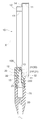
- FIG. 3 is a cross-sectional view of the sensor unit.
- FIG. 3 is a perspective view of a fixing member.
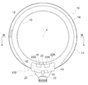
- FIG. 5 is a perspective view of a fixing member that forms a case. These are top views of the fixing member which formed the case.
- FIG. 6 is a sectional view taken along line VI-VI in FIG.
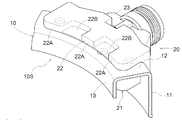
- FIG. 5 is a partially cutaway perspective view of a part where a case is formed as viewed from the outer surface side.
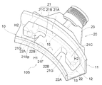
- FIG. 5 is a partially cutaway perspective view of a portion where a case is formed as viewed from the inner surface side. These are the figures which looked at the site
- FIG. 10 is a sectional view taken along line XX of FIG. These are sectional drawings which show the state which has arrange
- FIG. 12 is a sectional view taken along line XII-XII in FIG. These are sectional drawings of the state which inserted the sensor in the case in which the fixing member was formed.
- FIGS. 1 and 2 an annular fixing member 10 centering on the axis X, a case 20 integrally formed with the fixing member 10 by resin molding, and a sensor housing portion 20 ⁇ / b> S of the case 20.
- the sensor unit includes the sensor 30 housed in the sensor unit.
- This sensor unit is used to detect the rotation of a rotating shaft such as an axle of a vehicle, and as a sensor 30, a Hall element or a magnet that detects magnetism of a magnet (permanent magnet) that rotates integrally with an axle (not shown) or the like. Magnetosensitive elements such as resistance effect elements are used.
- the fixing member 10 has a cylindrical outer wall 11 having a cylindrical shape centered on the axis X and a posture orthogonal to the axis X from one end of the cylindrical outer wall 11.
- the cylindrical inner wall 13 having a cylindrical shape centered on the axis X on the inner peripheral side of the end wall 12 are integrally formed of a metal material such as steel or stainless steel. It has a formed structure.
- an intermediate wall 14 is formed at a part of the intermediate position between the cylindrical outer wall 11 and the end wall 12 so as to be orthogonal to the axis.
- a sensor forming region 10S is set in a portion of the fixing member 10 where the above-described intermediate wall 14 is not formed, and an outer wall portion opening 15 is formed in the cylindrical outer wall 11 of the sensor forming region 10S.
- a single first through hole H1 and a pair of second through holes H2 are formed in a posture parallel to the axis X.
- the case 20 includes a main case portion 21 formed from the inner surface of the cylindrical outer wall 11 of the fixing member 10 to the inner surface of the end wall 12, a sub case portion 22 formed on the outer surface of the end wall 12, and a cylinder And a projecting case portion 23 formed on the outer surface of the outer wall 11.
- a region extending from the inner surface of the cylindrical outer wall 11 of the fixing member 10 to the inner surface of the end wall 12 is a specific example of one surface of the fixing member 10
- the outer surface of the end wall 12 is the other surface of the fixing member 10. It is a specific example of a surface.
- the main case portion 21, the sub case portion 22, and the protruding case portion 23 are integrally formed of resin, and form a cavity along the radial direction of the fixing member 10 from the protruding case portion 23 to the main case portion 21.
- 20S is formed in a hole shape.
- the sensor housing portion 20S is formed in a region that passes through the outer wall portion opening 15.
- the sensor 30 has a sensor main body 31 composed of a magnetosensitive element, and a shaft-shaped portion 32 connected to the sensor main body 31, and a cable 33 is drawn from the end of the shaft-shaped portion 32.
- the sensor 30 is accommodated in the sensor accommodating portion 20 ⁇ / b> S, and a protective body 25 is formed so as to cover the outer surface of the protruding case portion 23.
- the circumferential direction around the axis X of the fixing member 10 is referred to as the width direction of the case 20, and the direction along the axis X is referred to as the thickness direction.
- the main case portion 21 is formed with a base region 21A (an example of a base portion, a portion close to the protruding case portion 23) that is in close contact with the cylindrical outer wall 11, and the base region 21A.
- a projecting region 21B projecting in the direction of the axis X is formed at a central position in the width direction in a state of being connected to the base region 21A.
- a pair of connection portions 21C that are in a positional relationship sandwiching the protruding region 21B are formed at positions adjacent to the protruding region 21B in a state where the protruding end side is separated from the protruding region 21B while being connected to the base region 21A. ing.
- a recessed portion 21G that opens in the direction of the axis X is formed between the protruding region 21B and the connecting portion 21C.
- the sensor accommodating portion 20S is formed inside the protruding area 21B, and a flat sensing surface 21F is formed on the outer surface of the protruding area 21B.
- the distance (thickness) between the sensing surface 21F and the inner surface of the sensor housing portion 20S is set to about 0.7 mm.
- the sub case portion 22 has a dimension substantially equal to that of the main case portion 21 in the width direction, and is formed in a region overlapping the main case portion 21 in the thickness direction. As shown in FIGS. 5, 7, and 10, the sub case portion 22 has a thick portion 22 ⁇ / b> A having a set thickness at a portion close to the projecting case portion 23, and the sub case portion 22 has an axial center X. In the adjacent parts, thin portions 22B thinner than the thick portions 22A are formed at two locations across the center position in the width direction.
- the thick part 22A is formed at the center position and both end parts in the width direction, and the thin part 22B is formed at the intermediate position between them.
- the thicknesses of the thick portion 22A and the thin portion 22B are thicknesses based on the upper surface of the end wall 12 of the fixing member 10.
- the protruding end side close to the axis X of the sensing surface 21F has an extended portion 21Bp (a corner portion of the sensing surface 21F) in which one side portion of the protruding end portion is drawn in the width direction.
- the first through-hole H1 is disposed at the boundary position between the extending portion 21Bp and the sensing surface 21F when viewed in the direction along the axis X. Further, the first through hole H ⁇ b> 1 is formed at a position overlapping the thin portion 22 ⁇ / b> B of the sub case portion 22.
- the projecting part of the sensing surface 21F of the present invention has two corners. It can be said that it is the shape which formed extension part 21Bp by extending only one side to the width direction (circumferential direction centering on the axial center X).
- the cylindrical outer wall 11 of the sensor unit is fixed in a state of being externally fitted to a fixing system such as an outer race of a ball bearing that rotatably supports an axle or the like, so that the main case portion 21 of the sensor unit is obtained.
- the sensing surface 21F can be disposed at a position close to the rotation region of the magnet that rotates integrally with the axle or the like. From such an arrangement, the magnetosensitive element detects the magnetism of a magnet (permanent magnet) that rotates integrally with the axle or the like.
- the first through hole H1 is a circle on the basis of a virtual center straight line Y connecting the center position of the opening width W of the outer wall opening 15 and the axis X at a position near the cylindrical inner wall 13 in the end wall 12. It is formed at a position deviated in the circumferential direction. Further, the second through hole H2 is formed at a position that is symmetric with respect to a virtual center straight line Y that connects the center position of the opening width W of the outer wall opening 15 and the axis.
- the sensor accommodating portion 20S is formed along the virtual center straight line Y described above.
- region (one surface of the fixing member 10) ranging from the inner surface side of the cylindrical outer wall 11 to the inner surface side of the end wall 12 among the fixing members 10, and a cylinder
- a first mold M1 that is in close contact with the outer surface of the outer wall 11 is disposed.
- the second mold M ⁇ b> 2 that is in close contact with the cylindrical outer wall 11 from the outer surface side of the end wall 12 (the other surface of the fixing member 10) is disposed. Furthermore, it arrange
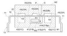
- a main cavity portion is formed between the first mold M1 and the fixing member 10, and between the second mold M2 and the fixing member 10 A sub-cavity portion is formed at. Further, a protruding cavity portion 44 that forms a protruding case portion 23 is formed outside the cylindrical outer wall 11 between the first mold M1 and the second mold M2.
- a central space 41 for forming the protruding region 21B as the main cavity, and a pair of A side space 42 for forming the connecting portion 21C and a base space 43 connected thereto are formed.
- the sensing surface 21F (see FIG. 10) described above is formed by the central molding surface 41S of the inner wall on the opposite side of the end wall 12 in the central space 41.
- an auxiliary filling space 41 ⁇ / b> A is formed at the projecting side end of the central space 41 so as to form the extending portion 21 ⁇ / b> Bp in a form protruding from the central space 41 in the width direction.
- a first through hole H ⁇ b> 1 is formed at a boundary position between the auxiliary filling space 41 ⁇ / b> A and the central space 41.
- the core M3 is accommodated in the central space 41, and the distance between the central molding surface 41S of the central space 41 and the core M3 is set to about 0.7 mm.
- thick part spaces 45 for forming the thick part 22A and a pair of thin part spaces 46 for forming the thin part 22B are formed in the sub-cavity part.
- the thick part space 45 of the both ends position in the width direction and the side part space 42 mentioned above are connected by the 2nd through-hole H2.
- a gate G serving as a filling position for filling a molten resin is formed at a position communicating with one of the pair of thin wall spaces 46, and the resin filling direction in the gate G is extended.
- the first through hole H1 is disposed on the line. As described above, the first through hole H1 is disposed at a position communicating with the boundary between the central space 41 and the auxiliary filling space 41A.
- the filling line P coincides with the center of the first through hole H1.
- the auxiliary filling space 41A, the first through hole H1, and the gate G are formed at positions that do not overlap with the core M3 when viewed in the direction along the axis X.
- the air in the central space 41 flows into the pair of side spaces 42 and can flow from the side spaces 42 to the second mold M2 through the second through holes H2. For this reason, the resin flows well inside the main case portion 21.
- the molten resin flows in a fan-like shape from the auxiliary filling space 41A (corner) of the central space 41, and the resin is filled to the other corner of the central space 41, Furthermore, it flows from the central space 41 to the base space 43, and then flows from the base space 43 to the pair of side spaces 42, and these spaces are filled with resin.
- the first mold M1 has a structure in which the region close to the axis X is separated in the central space 41 and the pair of side spaces 42, the resin supplied to the corners of the central space 41 is the side portion. The phenomenon of flowing linearly with respect to the space 42 is suppressed.
- heat radiation does not cause a disadvantage that the resin immediately before solidification flows backward from the side space 42 to the central space 41. As a result, no weld is generated.
- the molten resin supplied to the central space 41 flows from the base space 43 to the outer wall portion opening 15 and from the outer wall portion opening 15 to the protruding cavity portion 44 for forming the protruding case portion 23.
- the resin thus flowing further flows into the subcavity of the second mold M2 along the outer surface of the cylindrical outer wall 11, and further flows into the thick part space 45 and the thin part space 46, and into these spaces.
- the resin is full.
- the resin that has flowed into the pair of side spaces 42 flows from the second through hole H2 to the thick wall space 45, and the thick wall portion is also affected by the flow of such resin.
- the space 45 and the thin wall portion space 46 connected to the space 45 are filled.
- thermoplastic material that melts by heating such as nylon
- a material other than nylon may be used as the resin.
- the first mold M1 and the second mold M2 are removed, and the core M3 is extracted, so that the case 20 is formed integrally with the fixing member 10 as shown in FIG. Thereafter, the sensor 30 is inserted into the sensor housing portion 20S, and the protective body 25 is formed by molding to complete the sensor unit.
- die M1 is passed through the 1st through-hole H1 of the edge part wall 12. Since the resin can be directly filled into the cavity, for example, the path for filling the resin can be simplified as compared with the case where the gate G is formed in the first mold M1.
- the first through hole H1 is located at a position overlapping the protruding end portion of the protruding region 21B, A gate G may be arranged. In such a configuration, it is desirable to set the position of the first through hole H1 in the vicinity of the corner of the protruding region 21B in order to suppress the occurrence of welds.
- the sensor housing portion 20S is formed as a space
- the sensor unit is configured by molding with a mold in a form in which the sensor 30 is inserted into the sensor housing portion 20S. Even when the sensor unit is configured in this manner, an increase in the thickness of the sensing surface 21F can be suppressed, and the occurrence of welds at this portion can be suppressed.
- the first mold M1, the second mold M2, and the core M3 are used for forming the case 20, but in order to form the protruding case portion 23 of the case 20, the fixing member 10 is used.
- Auxiliary molds placed outside of the are used.
- the present invention can be used for a sensor unit in which a case is integrally formed by molding on an annular fixing member.
Landscapes
- Physics & Mathematics (AREA)
- General Physics & Mathematics (AREA)
- Engineering & Computer Science (AREA)
- Manufacturing & Machinery (AREA)
- Mechanical Engineering (AREA)
- Condensed Matter Physics & Semiconductors (AREA)
- Transmission And Conversion Of Sensor Element Output (AREA)
- Injection Moulding Of Plastics Or The Like (AREA)
Description
これにより、センサ収容部外面のセンシング面の厚みを適正にする成形を行うと共に、ウエルドの発生を抑制したセンシングユニットが構成された。
図1及び図2に示すように、軸芯Xを中心とする環状の固定部材10と、この固定部材10に対して樹脂成形により一体形成されるケース20と、このケース20のセンサ収容部20Sに収容されるセンサ30とを備えてセンサユニットが構成されている。
センサユニットを製造する場合には、固定部材10のセンサ形成領域10Sに位置する筒状外壁11に対して外壁部開口15を形成し、このセンサ形成領域10Sの端部壁12に対して軸芯Xと平行する単一の第1貫通孔H1と一対の第2貫通孔H2を形成する(図3を参照)。
本発明は、上記した実施形態以外に以下のように構成しても良い。
Claims (4)
- 軸芯を中心とする環状の固定部材に取り付けられる樹脂製のケースと、このケースのセンサ収容部に収容されたセンサとを備えると共に、
前記軸芯を中心にして回転する検出対象に対向するセンシング面が、前記ケースの前記センサ収容部の外面に形成され、
型を用いて前記ケースを成形する際の樹脂の充填位置が、前記センシング面において前記軸芯を中心とする円周方向に沿う幅の中央位置を基準にして前記円周方向に外れた位置に設定されているセンサユニット。 - 前記ケースが、前記センサ収容部を有し前記固定部材の一方の面に形成される主ケース部と、前記固定部材の他方の面に形成される副ケース部とを備えて構成され、
前記固定部材に対して前記一方の面から前記他方の面に貫通する第1貫通孔が、前記充填位置において樹脂の充填方向の延長線上に形成され、
前記副ケース部が、前記固定部材の外壁面を基準にした厚みが設定値となる厚肉部と、この厚肉部より薄い薄肉部とを備え、前記薄肉部が前記第1貫通孔と重複する位置に形成されている請求項1記載のセンサユニット。 - 前記充填位置が、前記センシング面の隅部に対応する位置に設定されている請求項1又は2記載のセンサユニット。
- 前記センサ収容部が、前記ケースの基部から前記軸芯の方向に突出する突出領域に形成され、前記充填位置が、前記突出領域に形成された前記センシング面において前記軸芯の方向に変位する位置の隅に対応する位置に形成されると共に、
前記基部に繋がり前記軸芯の方向に突出する端部で分離し、前記センシング面に隣接する接続部が、前記センシング面が形成された部位と並列する位置に形成されている請求項3記載のセンサユニット。
Priority Applications (2)
| Application Number | Priority Date | Filing Date | Title |
|---|---|---|---|
| US14/425,365 US9561608B2 (en) | 2012-10-03 | 2013-09-25 | Sensor unit |
| CN201390000793.6U CN204613229U (zh) | 2012-10-03 | 2013-09-25 | 传感器单元 |
Applications Claiming Priority (2)
| Application Number | Priority Date | Filing Date | Title |
|---|---|---|---|
| JP2012221585A JP5857932B2 (ja) | 2012-10-03 | 2012-10-03 | センサユニットの製造方法 |
| JP2012-221585 | 2012-10-03 |
Publications (1)
| Publication Number | Publication Date |
|---|---|
| WO2014054481A1 true WO2014054481A1 (ja) | 2014-04-10 |
Family
ID=50434809
Family Applications (1)
| Application Number | Title | Priority Date | Filing Date |
|---|---|---|---|
| PCT/JP2013/075839 Ceased WO2014054481A1 (ja) | 2012-10-03 | 2013-09-25 | センサユニット |
Country Status (4)
| Country | Link |
|---|---|
| US (1) | US9561608B2 (ja) |
| JP (1) | JP5857932B2 (ja) |
| CN (1) | CN204613229U (ja) |
| WO (1) | WO2014054481A1 (ja) |
Families Citing this family (2)
| Publication number | Priority date | Publication date | Assignee | Title |
|---|---|---|---|---|
| JP6971143B2 (ja) * | 2017-12-20 | 2021-11-24 | 株式会社小野測器 | ロータリエンコーダ |
| FR3086891B1 (fr) * | 2018-10-03 | 2020-12-18 | Valeo Systemes Thermiques | Composant electronique pour vehicule automobile |
Citations (4)
| Publication number | Priority date | Publication date | Assignee | Title |
|---|---|---|---|---|
| JP2005233849A (ja) * | 2004-02-20 | 2005-09-02 | Denso Corp | 回転検出装置 |
| JP2010043888A (ja) * | 2008-08-11 | 2010-02-25 | Ntn Corp | 回転検出センサ |
| JP2010125822A (ja) * | 2008-12-01 | 2010-06-10 | Tigers Polymer Corp | 環状樹脂成形品 |
| WO2012114703A1 (ja) * | 2011-02-24 | 2012-08-30 | アイシン精機株式会社 | 回転速度検出装置 |
Family Cites Families (19)
| Publication number | Priority date | Publication date | Assignee | Title |
|---|---|---|---|---|
| US4002937A (en) * | 1975-07-03 | 1977-01-11 | Dickey-John Corporation | Magnetic sensing device |
| US4302692A (en) * | 1978-02-06 | 1981-11-24 | Matsushita Electric Industrial Co., Ltd. | Rotational speed signal sensor |
| JPS6225267A (ja) * | 1985-07-26 | 1987-02-03 | Honda Motor Co Ltd | 磁気信号発生リング |
| NO975614A (no) * | 1997-12-04 | 1999-04-26 | Seas Fabrikker As | Permanentmagnetmontasje |
| EP1557676B1 (en) * | 2002-10-28 | 2015-05-06 | NSK Ltd. | Rolling bearing with sensor |
| JP2004222356A (ja) * | 2003-01-10 | 2004-08-05 | Moric Co Ltd | 回転電気機器 |
| KR20050098290A (ko) * | 2003-02-03 | 2005-10-11 | 고요 세이코 가부시키가이샤 | 센서 조립체, 시일 장치 및 차량용 구름 베어링 장치 |
| US20070177834A1 (en) * | 2003-10-29 | 2007-08-02 | Jtekt Corporation | Seal device with sensor and rolling bearing device using the seal device |
| JP4224382B2 (ja) * | 2003-11-18 | 2009-02-12 | 株式会社日立製作所 | 回転位置センサ及び内燃機関の電子制御式スロットル装置 |
| JP4085074B2 (ja) * | 2004-06-24 | 2008-04-30 | ファナック株式会社 | 磁気式角度検出器における回転体の製造方法 |
| JP2007040316A (ja) * | 2005-07-29 | 2007-02-15 | Smc Corp | 環状磁石およびそれを用いた流体圧シリンダ |
| JP5214869B2 (ja) * | 2006-10-30 | 2013-06-19 | Ntn株式会社 | 回転センサ付き転がり軸受 |
| US7999432B2 (en) * | 2007-08-17 | 2011-08-16 | Kura Laboratory Corporation | Field controllable rotating electric machine system with magnetic excitation part |
| JP5081553B2 (ja) * | 2007-09-27 | 2012-11-28 | Ntn株式会社 | 回転検出装置および回転検出装置付き軸受 |
| JP2009264941A (ja) | 2008-04-25 | 2009-11-12 | Denso Corp | 回転速度検出装置 |
| US20110127995A1 (en) | 2008-08-11 | 2011-06-02 | Kentarou Nishikawa | Rotation sensor |
| US8870408B2 (en) * | 2012-04-02 | 2014-10-28 | Streamlight, Inc. | Portable light and work light adapter therefor |
| JP5655826B2 (ja) * | 2012-08-24 | 2015-01-21 | 株式会社デンソー | 回転検出装置およびその製造方法 |
| US9976874B2 (en) * | 2013-07-16 | 2018-05-22 | Ntn Corporation | Magnetic encoder device and rotation detection device |
-
2012
- 2012-10-03 JP JP2012221585A patent/JP5857932B2/ja not_active Expired - Fee Related
-
2013
- 2013-09-25 CN CN201390000793.6U patent/CN204613229U/zh not_active Expired - Lifetime
- 2013-09-25 WO PCT/JP2013/075839 patent/WO2014054481A1/ja not_active Ceased
- 2013-09-25 US US14/425,365 patent/US9561608B2/en active Active
Patent Citations (4)
| Publication number | Priority date | Publication date | Assignee | Title |
|---|---|---|---|---|
| JP2005233849A (ja) * | 2004-02-20 | 2005-09-02 | Denso Corp | 回転検出装置 |
| JP2010043888A (ja) * | 2008-08-11 | 2010-02-25 | Ntn Corp | 回転検出センサ |
| JP2010125822A (ja) * | 2008-12-01 | 2010-06-10 | Tigers Polymer Corp | 環状樹脂成形品 |
| WO2012114703A1 (ja) * | 2011-02-24 | 2012-08-30 | アイシン精機株式会社 | 回転速度検出装置 |
Also Published As
| Publication number | Publication date |
|---|---|
| JP5857932B2 (ja) | 2016-02-10 |
| US9561608B2 (en) | 2017-02-07 |
| CN204613229U (zh) | 2015-09-02 |
| JP2014074619A (ja) | 2014-04-24 |
| US20150217495A1 (en) | 2015-08-06 |
Similar Documents
| Publication | Publication Date | Title |
|---|---|---|
| US9505431B2 (en) | Rotation detection device and power steering device | |
| JP5994286B2 (ja) | トルク検出装置およびその製造方法 | |
| KR101206864B1 (ko) | 모터 및 그 제조방법 | |
| JP5384958B2 (ja) | モータ及びその製造方法 | |
| CN111033950B (zh) | 转子、辐条型马达、车辆用马达、无人飞行体、电动助力装置以及机器人装置 | |
| US10683032B2 (en) | Torque detection device and electric power steering system | |
| US9228861B2 (en) | Rotation sensing apparatus and manufacturing method thereof | |
| US11177723B2 (en) | Rotor and motor | |
| US20160124056A1 (en) | Sensing device and method for manufacturing sensing device | |
| JP7163926B2 (ja) | ロータ、スポーク型モータ、車両用モータ、無人飛行体、電動アシスト装置およびロボット装置 | |
| JP5857932B2 (ja) | センサユニットの製造方法 | |
| US9378881B2 (en) | Yoke unit, yoke unit manufacturing method, torque detection device, and electric power steering device | |
| JP5978876B2 (ja) | トルク検出装置、および同装置を備えるステアリング装置 | |
| US11108288B2 (en) | Rotor and motor | |
| US11201513B2 (en) | Rotor and motor | |
| JP6344043B2 (ja) | センサ | |
| KR101992277B1 (ko) | 토크 센서 | |
| JP2019200135A (ja) | トルク検出装置および電動パワーステアリング装置 | |
| JP6019560B2 (ja) | ハブユニット軸受 | |
| CN106005025B (zh) | 防干扰罩 | |
| JP7106947B2 (ja) | 位置検出装置 | |
| CN110999031B (zh) | 马达 | |
| JP2008157762A (ja) | トルク測定器 | |
| US20250189389A1 (en) | Sensor device | |
| JP2019083665A (ja) | ステータユニット、モータ、及びファンモータ |
Legal Events
| Date | Code | Title | Description |
|---|---|---|---|
| WWE | Wipo information: entry into national phase |
Ref document number: 201390000793.6 Country of ref document: CN |
|
| 121 | Ep: the epo has been informed by wipo that ep was designated in this application |
Ref document number: 13843947 Country of ref document: EP Kind code of ref document: A1 |
|
| WWE | Wipo information: entry into national phase |
Ref document number: 14425365 Country of ref document: US |
|
| NENP | Non-entry into the national phase |
Ref country code: DE |
|
| 122 | Ep: pct application non-entry in european phase |
Ref document number: 13843947 Country of ref document: EP Kind code of ref document: A1 |