WO2014051152A1 - 磁気ディスク用ガラス基板、磁気ディスク - Google Patents
磁気ディスク用ガラス基板、磁気ディスク Download PDFInfo
- Publication number
- WO2014051152A1 WO2014051152A1 PCT/JP2013/076614 JP2013076614W WO2014051152A1 WO 2014051152 A1 WO2014051152 A1 WO 2014051152A1 JP 2013076614 W JP2013076614 W JP 2013076614W WO 2014051152 A1 WO2014051152 A1 WO 2014051152A1
- Authority
- WO
- WIPO (PCT)
- Prior art keywords
- magnetic disk
- glass substrate
- polishing
- magnetic
- glass
- Prior art date
- Legal status (The legal status is an assumption and is not a legal conclusion. Google has not performed a legal analysis and makes no representation as to the accuracy of the status listed.)
- Ceased
Links
Images


Classifications
-
- G—PHYSICS
- G11—INFORMATION STORAGE
- G11B—INFORMATION STORAGE BASED ON RELATIVE MOVEMENT BETWEEN RECORD CARRIER AND TRANSDUCER
- G11B5/00—Recording by magnetisation or demagnetisation of a record carrier; Reproducing by magnetic means; Record carriers therefor
- G11B5/74—Record carriers characterised by the form, e.g. sheet shaped to wrap around a drum
- G11B5/82—Disk carriers
-
- G—PHYSICS
- G11—INFORMATION STORAGE
- G11B—INFORMATION STORAGE BASED ON RELATIVE MOVEMENT BETWEEN RECORD CARRIER AND TRANSDUCER
- G11B5/00—Recording by magnetisation or demagnetisation of a record carrier; Reproducing by magnetic means; Record carriers therefor
- G11B5/62—Record carriers characterised by the selection of the material
- G11B5/73—Base layers, i.e. all non-magnetic layers lying under a lowermost magnetic recording layer, e.g. including any non-magnetic layer in between a first magnetic recording layer and either an underlying substrate or a soft magnetic underlayer
- G11B5/739—Magnetic recording media substrates
- G11B5/73911—Inorganic substrates
- G11B5/73921—Glass or ceramic substrates
Definitions
- the present invention relates to a glass substrate for a magnetic disk and a magnetic disk.
- a personal computer or a DVD (Digital Versatile Disc) recording device has a built-in hard disk device (HDD: Hard Disk Drive) for data recording.
- HDD Hard Disk Drive
- a magnetic disk in which a magnetic layer is provided on a glass substrate is used, and the magnetic head slightly floats above the surface of the magnetic disk.
- the rotational speed of the magnetic disk at this time is, for example, about 5400 rpm.
- a glass substrate having a higher rigidity and higher impact resistance than a metal substrate (aluminum substrate) or the like is preferably used.
- the thickness of the magnetic disk glass substrate is typically 0.635 mm or 0.8 mm in the case of a 2.5-inch magnetic disk, for example.
- fluttering is a phenomenon in which the substrate vibrates (flutters) as the substrate rotates.
- Patent Document 1 in order to reduce fluttering during high-speed rotation, the maximum value Smax and the minimum value Smin of the interval S from the inner periphery to the outer periphery of the projected image projected on a plane parallel to the main surface are Discloses a glass substrate for a magnetic disk with a difference ⁇ S of less than 2 ⁇ m.
- the difference between the maximum value and the minimum value of the distance from the inner periphery to the outer periphery of the main surface is specified.
- fluttering during high-speed rotation may occur due to the end face shape of the glass substrate.
- an object of the present invention is to provide a magnetic disk glass substrate and a magnetic disk that can further reduce fluttering during high-speed rotation.
- the inventors of the present application have found that the outer peripheral end surface of the glass substrate (a side wall surface orthogonal to the main surface and a chamfered surface between the main surface and the side wall surface) It was found that fluttering can be further reduced by reducing the change in shape in the circumferential direction.
- the present inventors consider the reason as follows. That is, when the change in the shape of the outer peripheral end face in the circumferential direction of the glass substrate in a short cycle increases, the amount of air in contact with the outer peripheral end face changes greatly, thereby stabilizing the airflow around the outer peripheral end face accompanying the rotation of the substrate. It is thought that it will not.
- a wall (shroud) that covers the outer periphery of the magnetic disk mounted on the spindle may be provided, and the gap between the wall and the outer peripheral end surface of the magnetic disk is reduced. This makes it possible to stabilize the airflow in the gap.
- the change in the shape of the outer peripheral end face in the circumferential direction of the glass substrate increases in a state where the gap is small, the rate of change in the gap between the wall and the outer peripheral end face of the magnetic disk increases. It is conceivable that the airflow in the air tends to be disturbed.
- the change in the shape of the outer peripheral end surface in the circumferential direction of the glass substrate is reduced, the air flow around the outer peripheral end surface of the glass substrate can be stabilized, and the gap between the wall and the outer peripheral end surface of the magnetic disk can be substantially reduced. Since it can be kept constant, fluttering can be further reduced.
- a first aspect of the present invention is that an outer peripheral end face and an inner circumference are formed of a pair of main surfaces, a side wall surface, and a chamfered surface formed between the main surface and the side wall surface.
- a glass substrate for a donut-shaped magnetic disk having an end surface, wherein a measurement point is provided every 30 degrees in the circumferential direction with respect to the center of the glass substrate at the outer peripheral end surface, and the side wall surface and the chamfered surface A glass substrate for a magnetic disk, wherein a difference in the radius of curvature between adjacent measurement points is 0.01 mm or less when the radius of curvature at the measurement point of the shape of the portion in between is obtained.
- the difference in the radius of curvature between adjacent measurement points is 0.005 mm or less.
- a measurement point is provided every 30 degrees in the circumferential direction with respect to the center of the glass substrate, and a radius of curvature at the measurement point of a shape of a portion between the main surface and the chamfered surface Is determined as the second radius of curvature, the difference in the second radius of curvature between adjacent measurement points is preferably 0.004 mm or less.
- the glass substrate for a magnetic disk, the glass substrate preferably has a thickness of 0.635 mm or less.
- a second aspect of the present invention is a magnetic disk in which at least a magnetic layer is formed on the glass substrate for a magnetic disk.
- the top view of the glass substrate for magnetic discs of embodiment The figure which shows the expanded cross section of XX of FIG. 1A. The figure which expands and shows a part of FIG. 1B further. The principal part enlarged view of FIG. 1B.
- Aluminosilicate glass, soda lime glass, borosilicate glass, or the like can be used as the material for the magnetic disk glass substrate in the present embodiment.
- aluminosilicate glass can be suitably used in that it can be chemically strengthened and a glass substrate for a magnetic disk excellent in the flatness of the main surface and the strength of the substrate can be produced. More preferably, it is an amorphous aluminosilicate glass.
- the composition of the glass substrate for a magnetic disk of this embodiment is not limited, the glass substrate of this embodiment is preferably converted to an oxide standard and expressed in mol%, SiO 2 is 50 to 75%, Al 2 to O 3 to 1 to 15%, at least one component selected from Li 2 O, Na 2 O and K 2 O in total 5 to 35%, selected from MgO, CaO, SrO, BaO and ZnO 0-20% in total of at least one component, and at least one selected from ZrO 2 , TiO 2 , La 2 O 3 , Y 2 O 3 , Ta 2 O 5 , Nb 2 O 5 and HfO 2 An amorphous aluminosilicate glass having a composition having a total of 0 to 10% of components (hereinafter referred to as “glass composition 1”).
- the glass substrate of the present embodiment is preferably 57% to 75% SiO 2 , 5% to 20% Al 2 O 3 in mass% as disclosed in, for example, Japanese Patent Application Laid-Open No. 2009-99239, ( However, the total amount of SiO 2 and Al 2 O 3 is 74% or more), ZrO 2 , HfO 2 , Nb 2 O 5 , Ta 2 O 5 , La 2 O 3 , Y 2 O 3 and TiO 2 in total 0 %, 6% or less, Li 2 O more than 1%, 9% or less, Na 2 O 5 to 18% (however, the mass ratio Li 2 O / Na 2 O is 0.5 or less), K 2 0 to 6% for O, 0 to 4% for MgO, more than 0% for CaO and 5% or less (however, the total amount of MgO and CaO is 5% or less, and the content of CaO is the content of MgO) More), an amorphous composition comprising 0 to 3% of SrO + Ba
- the glass substrate of the present embodiment is SiO 2 : 45.60 to 60%, Al 2 O 3 : 7 to 20%, and B 2 O 3 : 1.00 to less than 8%, and P 2 O 5 : 0.50 to 7%, and TiO 2 : 1 to 15%, and the total amount of RO: 5 to 35% (where R is Zn and Mg), the CaO content is 3.00% or less, the BaO content is 4% or less, the PbO component, the As 2 O 3 component, the Sb 2 O 3 component, and Cl ⁇ , NO.
- the crystal grain size of the main crystal phase is 0.5 nm to 20 It may be a crystallized glass having a range of nm, a crystallinity of 15% or less, and a specific gravity of 2.95 or less.
- the composition of the glass substrate for a magnetic disk according to the present embodiment includes, as an essential component, at least one alkaline earth metal selected from the group consisting of SiO 2 , Li 2 O, Na 2 O, and MgO, CaO, SrO, and BaO.
- the molar ratio of the CaO content to the total content of MgO, CaO, SrO and BaO (CaO / (MgO + CaO + SrO + BaO)) is 0.20 or less and the glass transition temperature is 650 ° C. or more. Also good.
- a glass substrate for a magnetic disk having such a composition is suitable for a glass substrate for a magnetic disk used for a magnetic disk for energy-assisted magnetic recording (hereinafter referred to as “glass composition 2”).
- FIG. 1A to 1C and FIG. 2 show the shape of the magnetic disk glass substrate G of the present embodiment.
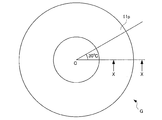
- FIG. 1A is a plan view of a glass substrate for a magnetic disk according to the present embodiment.
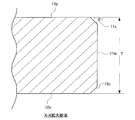
- FIG. 1B is an enlarged cross-sectional view taken along line XX in FIG. 1A.
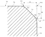
- FIG. 1C is an enlarged view of a part of FIG. 1B.
- FIG. 2 is an enlarged view of a main part of FIG. 1B.
- the glass substrate may be fixed so that the chamfered surface on the outer peripheral side is substantially horizontal, and the fixed glass substrate or the stylus of the contour shape measuring machine may be moved in the radial direction of the glass substrate.
- the magnetic disk glass substrate G of the present embodiment has a donut shape with a circular hole formed at the center and an annular outer shape.
- the magnetic disk glass substrate G of this embodiment includes a pair of main surfaces 11p and 12p, an inner peripheral side wall surface (that is, a circular hole side wall surface), and an outer peripheral side wall surface ( That is, it has two side wall surfaces (outer side wall surfaces).
- FIG. 1A the magnetic disk glass substrate G of the present embodiment has a donut shape with a circular hole formed at the center and an annular outer shape.
- the magnetic disk glass substrate G of this embodiment includes a pair of main surfaces 11p and 12p, an inner peripheral side wall surface (that is, a circular hole side wall surface), and an outer peripheral side wall surface ( That is, it has two side wall surfaces (outer side wall
- the side wall surface 11w of the glass substrate G is an outer peripheral side wall surface.
- the side wall surface 11w on the outer peripheral side of the glass substrate G preferably includes a surface orthogonal to each of the pair of main surfaces 11p and 12p.
- Chamfered surfaces 11c and 12c are formed between the pair of main surfaces 11p and 12p and the outer peripheral side wall surface 11w, respectively.
- FIG. 1B the case where the chamfered surfaces 11c and 12c are formed in a planar shape is shown as an example.
- the chamfered surfaces 11c and 12c are, for example, surfaces curved outward of the glass substrate G. It may be formed so as to include. In this case, it is preferable that the degree of bending is substantially constant along the circumferential direction of the glass substrate G.
- the shape of the edge part of the outer peripheral side of the glass substrate G for magnetic discs of this embodiment is demonstrated.
- the straight portions of the main surface 11p, the side wall surface 11w, and the chamfered surface 11c are denoted as Lp, Lw, and Lc, respectively.
- the intersection of the straight portion Lp of the main surface 11p and the straight portion Lc of the chamfered surface 11c is P11, and the intersection of the straight portion Lw of the side wall surface 11w and the straight portion Lc of the chamfered surface 11c.
- the angle (chamfering angle; ⁇ 1) formed by the straight line portion Lp of the main surface 11p and the straight line portion Lc of the chamfered surface 11c is preferably 40 to 70 degrees, for example.
- the angle (chamfering angle; ⁇ 2) formed by the straight line portion Lp of the main surface 11p and the straight line portion Lc of the chamfered surface 11c is preferably 20 to 50 degrees, for example.
- the distance D1 between the points P11 and P13 is preferably 0.05 to 0.20 mm, and the distance D2 between the points P12 and P13 is preferably 0.10 to 0.30 mm.
- outer peripheral side wall surface 11w and the chamfered surfaces 11c and 12c are collectively referred to as an outer peripheral end surface, and an inner peripheral side wall surface and a chamfered surface (not shown) are collectively referred to as an inner peripheral end surface.
- R is the radius of a circle C2 that forms the curvature of the shape of the portion between the side wall surface 11w and the chamfered surface 11c, and is the curvature radius of the shape of the portion.
- the curvature radius R can be determined as follows, for example. First, let P1 be the intersection of an imaginary line L1 extending the straight line portion of the chamfered surface 11c and a virtual line L2 extending the straight line portion of the side wall surface 11w.
- an imaginary line L3 passing through the intersection point P1 and extending perpendicularly to the straight portion of the chamfered surface 11c is set.
- an intersection between the portion between the side wall surface 11w and the chamfered surface 11c and the virtual line L3 is defined as P2.
- a circle C1 having a predetermined radius (for example, 50 ⁇ m) around the intersection P2 is set.
- two intersections of the part between the side wall surface 11w and the chamfering surface 11c, and the outer periphery of the circle C1 be P3 and P4, respectively.
- a circle C2 passing through each of the three intersections P2, P3, P4 is set.
- the radius of curvature R of the shape of the portion between the side wall surface 11w and the chamfered surface 11c is determined.
- the curvature radius of the shape of the part between the side wall surface 11w and the chamfered surface 12c can also be stopped similarly to the above.
- measurement points are provided every 30 degrees in the circumferential direction with reference to the center C of the glass substrate G (see FIG. 1A). That is, the number of measurement points is 12.
- the radius of curvature R of the shape of the portion between the side wall surface 11w and the chamfered surface 11c is determined, a total of twelve (the portion between the other chamfered surface of the disc is also a portion). 24) (including the shape), the difference (absolute value) in the radius of curvature R between adjacent measurement points is set to 0.01 mm or less.
- the change of the shape of the outer peripheral end surface in the circumferential direction of the glass substrate G can be reduced, when the magnetic disk manufactured using this glass substrate G is rotated at a high speed, the outer peripheral end surface of the magnetic disk The surrounding airflow can be stabilized. Further, when this magnetic disk is mounted on the spindle of a magnetic disk drive device, the gap between the outer wall of the magnetic disk (shroud) and the outer peripheral end surface of the magnetic disk can be kept substantially constant. The airflow in can be stabilized. Therefore, according to the glass substrate G of the present embodiment, fluttering during high-speed rotation can be further reduced. In addition, when the difference of the curvature radius R between adjacent measurement points is 0.005 mm or less, it is preferable at the point which can further reduce fluttering at the time of high speed rotation.
- the curvature radius (second curvature radius) of the shape of the portion between the main surface 11p and the chamfered surface 11c may be obtained. Specifically, an intersection of an imaginary line L1 extending the straight line portion of the chamfered surface 11c and an imaginary line L4 (not illustrated) extending the straight line portion of the main surface 11p is defined as P5 (not illustrated). Next, an imaginary line L5 (not shown) passing through the intersection point P5 and extending perpendicularly to the main surface 11p is set. Next, the intersection between the main surface 11p and the chamfered surface 11c and the virtual line L5 is defined as P6 (not shown).
- a circle C3 (not shown) having a predetermined radius (for example, 10 ⁇ m) around the intersection P6 is set. Further, two intersections between the portion between the main surface 11p and the chamfered surface 11c and the outer periphery of the circle C3 are defined as P7 and P8 (respectively omitted). Further, a circle C4 (not shown) passing through each of the three intersections P6, P7, P8 is set. Then, by determining the radius of the circle C4, the second curvature radius of the shape of the portion between the main surface 11p and the chamfered surface 11c is determined. In addition, the 2nd curvature radius of the shape of the part between the main surface 12p and the chamfering surface 12c can also be stopped similarly to the above.
- the second radius of curvature is determined at each measuring point (12 measuring points) between adjacent measuring points
- the difference in the second curvature radius may be set to 0.004 mm or less.
- the size of the magnetic disk glass substrate G of the present embodiment is not limited, but may be, for example, a nominal diameter of 2.5 inches.
- the glass substrate G for magnetic disk of the present embodiment may be used for a magnetic disk incorporated in a magnetic disk drive device mounted on a server device or a notebook personal computer, for example.
- the conventional magnetic disk since the conventional magnetic disk is operated at a high speed rotation of, for example, 10,000 rpm or more, it has been required to secure a desired plate thickness that does not cause fluttering at such a high speed rotation.
- magnetic disk drive devices have been reduced in size and thickness based on demands for reduction in size and thickness of notebook personal computers and the like. Accordingly, there is an increasing demand for thinning the magnetic disk.
- the conventional magnetic disk when the plate thickness is simply reduced (thinned), it becomes easy to be affected by the air flow accompanying the rotation of the magnetic disk, and it has been difficult to reduce fluttering. For this reason, it has been difficult for conventional magnetic disks to meet the demand for thinning.
- the present embodiment by reducing the change in the shape of the outer peripheral end face in the circumferential direction of the glass substrate G, the airflow around the outer peripheral end face of the magnetic disk can be stabilized, so the thickness of the glass substrate G is small. Even in this case, fluttering can be reduced. As a result, it is possible to meet the demand for a thinner magnetic disk.
- the plate thickness T of the glass substrate G (see FIG. 1B) is nominally 0.635 mm or less, the effect obtained by applying the configuration of the present embodiment becomes significant, which is preferable.
- the case where the plate thickness of the glass substrate is “nominal 0.635 mm” includes the case where the actual plate thickness is slightly thicker or slightly thinner than 0.635 mm.
- a glass base plate having a predetermined shape as a base of a magnetic disk glass substrate is cut out from the plate glass.
- the glass base plate may be formed by press molding using an upper mold and a lower mold, for example.
- a glass base plate can also be manufactured not only using these methods but using well-known manufacturing methods, such as a downdraw method, a redraw method, and a fusion method.
- a chamfering step for forming a chamfered surface at the end is performed.
- the chamfering process may be performed by using a conventionally known apparatus and method, for example, while supplying a grinding liquid to the grinding portion using a rotating general grinding wheel. Grooves may be formed in advance on the surface of the total-type grindstone so as to have a desired end shape after processing.
- the chamfering step first, the outer peripheral end and the inner peripheral end of the annular glass base plate are subjected to rough grinding using, for example, a relatively rough diamond grindstone to form a chamfered shape at a relatively high speed.
- the chamfered surface is finish-ground to a surface property close to a mirror surface.
- the surface roughness after finishing can be reduced by increasing the count of the grinding wheel used for grinding (that is, by reducing the grain size of the diamond abrasive grains). You can reduce your bill. Since the shape prepared in the grinding process is maintained as the machining allowance for end face polishing is smaller, the shape accuracy can be increased. That is, the difference in the radius of curvature at the measurement positions adjacent in the circumferential direction of the outer peripheral end can be reduced.
- End face polishing step end face polishing of an annular glass base plate is performed.
- the end surface polishing is performed by contacting the polishing means while rotating the glass base plate in the same manner as the chamfering step. Since there is no processing for grinding / polishing the end face after the end face polishing, the end face polishing plays an important role in substantially determining the final shape in the circumferential direction.
- a magnetic slurry is formed by holding the magnetic slurry along the lines of magnetic force, and this mass is brought into contact with the inner peripheral end surface and the outer peripheral end surface of the glass base plate to move relative to each other. Polishing the inner and outer peripheral edges of the plate. At this time, the side wall surface and the chamfered surface can be polished simultaneously.
- the magnetic slurry includes a magnetorheological fluid and fine particles such as cerium oxide and zirconium oxide as abrasive grains.
- a magnetorheological fluid for example, a fluid containing magnetic fine particles made of Fe and nonpolar or polar oil is used.
- the disturbance of the shape can be made extremely small, and the surface roughness and undulation can also be made extremely small.
- the hair tip bends or breaks when the tip of the brush contacts the workpiece surface, and the pressure when the tip of the brush contacts within the side wall surface or chamfered surface varies.
- the shape accuracy of the end face is deteriorated due to local deep blurring.
- the boundary portion between the side wall surface and the chamfered surface may be shaved unevenly in the circumferential direction, and the shape accuracy of the end surface may deteriorate.
- the machining allowance in the end surface polishing step of the present case can be significantly reduced as compared with a conventional method using a brush, and can be, for example, 10 ⁇ m or less.
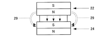
- FIG. 3A to FIG. 3C and FIG. 4 are diagrams for explaining an example of a polishing method in end face polishing in the present embodiment.
- the apparatus 20 for polishing the end surface polishes the end surface of the glass substrate using a magnetism generating means and a magnetic slurry.
- the outline of the apparatus 20 for performing end face polishing will be described.
- the apparatus 20 includes, for example, a pair of magnets 22 and 24 that are permanent magnets, a spacer 26, and a non-magnetic material such as a cylinder made of stainless steel.
- a pipe 28 having a shape. Magnets 22 and 24 and a spacer 26 are built in the pipe 28.
- the glass base plate for end face polishing is held by a holder (not shown).
- the pipe 28 is arrange
- the lump 30 formed by the magnets 22 and 24 in the pipe 28 is brought into contact with the outer peripheral end face of the glass base plate.
- a holder (not shown) that holds the pipe 28 and the glass base plate of the apparatus 20 is mechanically connected to a drive motor (not shown). By rotating the pipe 28 and the holder to relatively move the outer peripheral end surface of the glass base plate and the lump 30, the outer peripheral end surface of the glass base plate can be polished.
- the pipe 28 may be rotated at, for example, 500 to 5000 rpm.
- the glass base plate may be rotated at 10 to 1000 rpm, for example.
- the rotation direction of both at the processing point may be either down cut or up cut, but the down cut is preferable because it has a lower polishing rate but less variation in shape.
- both up-cut and down-cut if the difference in tangential speed between the glass substrate and the magnetic slurry at the processing point is 800 m / min or less, the variation in the shape in the circumferential direction is caused between one surface and the other surface. This is preferable because the difference between them (described later, the difference between the A surface and the B surface) can be reduced.
- the magnet 22 and the magnet 24 are close to each other and function as magnetism generating means, thereby forming a magnetic force line 29 that travels from the magnet 22 to the magnet 24 as shown in FIG. 3B.
- the magnetic force lines 29 proceed so as to protrude outward from the centers of the magnets 22 and 24, and proceed in the thickness direction of the glass base plate.
- a spacer 26 made of a non-magnetic material is provided in order to create a lump 30 of magnetic slurry on the outer periphery of the pipe 28 as shown in FIG. 3C.
- the magnetic flux density in the magnetism generating means may be set to such an extent that the magnetic slurry lump 30 is formed, but is preferably 0.1 to 10 Tesla from the viewpoint of efficient end face polishing.
- a permanent magnet is used as the magnetism generating means, but an electromagnet can also be used.
- the magnets 22 and 24 are fixed to the pipe 28 without using the spacer 26, and the separation distance between the N pole end face of the magnet 22 and the S pole end face of the magnet 24 can be secured constant.
- the abrasive grains contained in the magnetic slurry known abrasive grains of glass substrates such as cerium oxide, colloidal silica, zirconia oxide, alumina abrasive grains, diamond abrasive grains and the like can be used.
- the average particle diameter (D50) of the abrasive grains is, for example, 0.5 to 10 ⁇ m. By using abrasive grains in this range, the inner end face of the glass base plate can be satisfactorily polished.
- the abrasive grains are contained, for example, in an amount of 1 to 20 vol% in the magnetic slurry.
- the average particle diameter (D50) means a particle diameter at which the cumulative volume frequency calculated by the volume fraction is 50% calculated from the smaller particle diameter.
- Precision grinding process In a precision grinding process, it grinds with respect to the main surface of an annular
- the fixed abrasive grindstone for example, a grinding pad in which diamond abrasive grains are fixed with a resin can be used.
- the double-sided grinding apparatus has a pair of upper and lower surface plates (upper surface plate and lower surface plate), and an annular glass base plate is sandwiched between the upper surface plate and the lower surface plate. Then, by moving both the upper surface plate and the lower surface plate, or both of them, the main surface of the glass base plate is ground by relatively moving the glass base plate and each surface plate. be able to.
- polishing main surface grinding
- polishing is given to the main surface of the ground glass substrate.
- a double-side polishing apparatus having a planetary gear mechanism is used.
- an annular flat plate polishing pad is attached to the upper surface of the lower surface plate and the bottom surface of the upper surface plate as a whole.
- the glass element mounted on the carrier is used.
- the polishing pad is pressed against the plate, and the polishing liquid is supplied between the glass base plate and the polishing pad.
- the material of the polishing pad is, for example, foamed urethane.
- As the polishing liquid for example, a polishing liquid containing cerium oxide or zirconium oxide as polishing abrasive grains is used.
- polishing process is chemically strengthened.
- the chemical strengthening liquid for example, a mixed melt of potassium nitrate and sodium sulfate can be used. Chemical strengthening is performed by immersing a glass base plate in a chemical strengthening solution.
- Second Polishing is applied to the glass base plate that has been chemically strengthened and sufficiently cleaned.
- the second polishing for example, a polishing apparatus similar to the first polishing is used.
- the difference from the first polishing is that the type and particle size of the free abrasive grains are different and the hardness of the resin polisher is different.
- the free abrasive grains used in the second polishing for example, fine particles (particle size: diameter of about 10 to 50 nm) such as colloidal silica are used.
- a magnetic disk is obtained as follows using a magnetic disk glass substrate.
- the magnetic disk is, for example, on the main surface of a glass substrate for magnetic disk (hereinafter simply referred to as “substrate”), in order from the closest to the main surface, at least an adhesion layer, an underlayer, a magnetic layer (magnetic recording layer), and a protection A layer and a lubricating layer are laminated.
- the substrate is introduced into a film forming apparatus that has been evacuated, and a film is sequentially formed from an adhesion layer to a magnetic layer on the main surface of the substrate in an Ar atmosphere by a DC magnetron sputtering method.
- a CoPt alloy can be used as the adhesion layer
- CrRu can be used as the underlayer.
- a CoPt alloy can be used. It is also possible to form a CoPt-based alloy and FePt based alloy L 10 regular structure and magnetic layer for heat-assisted magnetic recording.
- a magnetic recording medium can be formed by forming a protective layer using, for example, C 2 H 4 by a CVD method and subsequently performing nitriding treatment for introducing nitrogen into the surface. Thereafter, for example, PFPE (perfluoropolyether) is applied on the protective layer by a dip coating method, whereby a lubricating layer can be formed.
- PFPE perfluoropolyether
- the manufactured magnetic disk is preferably a magnetic disk drive device (HDD) as a magnetic recording / reproducing device, which includes a magnetic head equipped with a DFH (Dynamic Flying Height) control mechanism and a spindle for fixing the magnetic disk. (Hard Disk Drive)).
- HDD magnetic disk drive device
- DFH Dynamic Flying Height
- Example 1 About the glass substrate for magnetic discs of Example 1, it produced by performing each process of the manufacturing method of the glass substrate for magnetic discs of this embodiment in order.
- a press molding method was used, followed by rough grinding with loose abrasive grains.
- a circular hole was formed at the center of the glass base plate using a cylindrical drill.
- rough grinding was performed to form a chamfered surface using a diamond grindstone with a particle size of # 400. Thereafter, the chamfered surface was finish-ground using a diamond grindstone with a grain size of # 2000.
- the shape of the chamfered part was set to 45 degrees for both ⁇ 1 and ⁇ 2 (see FIG. 1C). Further, the distance D1 shown in FIG. 1C is 0.15 mm, and the distance D2 is 0.15 mm.
- the front and back surfaces and the chamfered portions on the inner and outer peripheral sides have the same shape.
- end surface polishing of (4) end surface polishing was performed using the magnetic slurry described above.
- the magnetic slurry used was a magnetic fluid in which fine particles of Fe were dispersed in nonmagnetic oil and cerium oxide was dispersed as abrasive grains.
- a permanent magnet was used as the magnet, and it was processed by up-cutting.
- the chamfering allowance in the step (4) was 10 ⁇ m.
- grinding was performed using a grinding apparatus in which a diamond pad was fixed with a resin and a grinding pad that was a fixed abrasive grindstone was attached to a surface plate.
- a polishing liquid containing cerium oxide abrasive grains was used, and a hard urethane pad was used as the polishing pad.
- the glass base plate was immersed in a mixed melt of potassium nitrate and sodium nitrate as the chemical strengthening solution.
- a polishing liquid containing fine particles of colloidal silica was used as an abrasive. Thereafter, the glass base plate was washed to obtain a glass substrate for a magnetic disk.
- Example 2 A glass substrate for a magnetic disk was manufactured in the same manner as in Example 1 except that the allowance for end face polishing in (4) was 8 ⁇ m.
- Example 3 In the chamfering step of (3), after rough grinding using a diamond grindstone of particle size # 500, finish grinding using a diamond grindstone of particle size # 3000, and further, the allowance for end surface polishing of (4) was set to 8 ⁇ m.
- a magnetic disk glass substrate was produced in the same manner as in Example 2 except for the above.
- Example 4 A glass substrate for a magnetic disk was manufactured in the same manner as in Example 3 except that the allowance for the end surface polishing in (4) was 5 ⁇ m.
- Example 5 A glass substrate for a magnetic disk was manufactured in the same manner as in Example 3 except that the end face polishing in (4) was such that the rotation direction of the magnet and the glass base plate was downcut at the processing point.
- Example 6 A glass substrate for a magnetic disk was manufactured in the same manner as in Example 5 except that in the end surface polishing in (4), the machining allowance was 8 ⁇ m.
- Example 7 A glass substrate for a magnetic disk was manufactured in the same manner as in Example 5 except that in the end surface polishing of (4), the machining allowance was 4 ⁇ m.
- Comparative Example 1 On the other hand, in Comparative Example 1, in the chamfering of (3), rough grinding was performed to form a chamfered surface using a diamond grindstone having a particle size of # 400. In the comparative example, finish grinding is not performed. In the end face polishing of (4), the end face of the glass base plate was polished with a polishing brush using cerium oxide as the free abrasive grains. The chamfering allowance in the step (4) was 50 ⁇ m.
- measurement points are provided on the outer peripheral end surface every 30 degrees in the circumferential direction of the main surface with reference to the center of the main surface, and the side wall surface and the chamfered surface at each measurement point
- the radius of curvature of the shape of the part in the middle was determined.
- the curvature radius measured 24 points
- the difference in curvature radius when “0 to 30 degrees” means the absolute value of the difference between the curvature radius at the measurement point of 0 degrees and the curvature radius at the measurement point of 30 degrees. Further, for example, the back side of the 30-degree position on the A surface is set to the 30-degree position on the B surface.
- a magnetic disk having a magnetic layer formed on the obtained glass substrate for magnetic disk was produced. Thereafter, fluttering was evaluated for each of the magnetic disks of Examples and Comparative Examples using a laser Doppler vibrometer.
- a magnetic disk is mounted on a spindle of a hard disk drive (HDD) having a rotational speed of 7200 rpm, and laser light is irradiated from the laser Doppler vibrometer to the main surface of the rotating magnetic disk.
- the laser beam reflected by the magnetic disk is received by the laser Doppler vibrometer, thereby obtaining a vibration value in the thickness direction of the magnetic disk. More details are as follows.
- a magnetic disk is mounted on a 2.5-inch HDD spindle, the magnetic disk is rotated, and the main surface of the rotating magnetic disk is irradiated with laser light from a laser Doppler vibrometer. .
- a cover is properly attached and a hole for laser irradiation is formed in the HDD cover.
- the laser Doppler vibrometer receives the laser light reflected by the magnetic disk, and the amount of shake in the thickness direction of the magnetic disk is measured as a fluttering characteristic value.
- fluttering characteristic values were measured under the following conditions. ⁇ Environment of HDD and measurement system: Maintain the temperature at 25 ° C.
- Table 3 shows the evaluation of fluttering when the difference in radius of curvature between adjacent measurement points is 0.01 mm or less and the maximum difference in the second radius of curvature between adjacent measurement points is different. Results are shown. In addition, fluttering evaluation was performed in the same manner as described above except that a 2.5-inch HDD having a rotation speed of 10,000 rpm was used. As can be seen from Table 3, a better evaluation could be obtained when the difference in the second curvature radius between adjacent measurement points was 0.004 mm or less.
- a 2.5-inch magnetic disk is produced from a glass substrate for magnetic disk having a glass composition 2 different from the glass composition 1 described above.
- the method for producing the glass substrate for magnetic disk is the same as in the case of glass composition 1 (that is, the above (1) to (8)).
- the glass composition 2 is preferable as a glass composition used for the glass substrate for magnetic disks used for the magnetic disk for energy assist magnetic recording as mentioned above.
- Example 8 the radius of curvature of the shape of the portion between the side wall surface and the chamfered surface at each measurement point was determined at measurement points every 30 degrees in the circumferential direction of the main surface with reference to the center of the main surface. .
- the maximum value of the difference in curvature radius between adjacent measurement points was 0.01 mm.
- Example 9 A magnetic disk glass substrate was produced in the same manner as in Example 1 and Comparative Example 1 except that the center value of the plate thickness was 0.500 mm, and film formation was performed to obtain a magnetic disk (Example 9, Comparative example 3).
- a glass substrate for a magnetic disk was manufactured in the same manner as in Example 1 and Comparative Example 1 except that the center value of the plate thickness was 0.800 mm, and film formation was performed to obtain a magnetic disk (each of the examples). 10 and Comparative Example 4).
- a glass substrate for a magnetic disk was manufactured in the same manner as in Example 1 and Comparative Example 1 except that the center value of the plate thickness was 1.000 mm, and film formation was performed to obtain a magnetic disk (each of the examples). 11 and Comparative Example 5).
- Examples 9, 10, and 11 were the same as Example 1, and Comparative Examples 3, 4, and 5 were the same as Comparative Example 1.
- fluttering evaluation was performed in the same manner as described above except that a 2.5-inch HDD having a rotation speed of 5400 rpm was used. It was.
- the improvement width of the fluttering characteristic value (the value obtained by subtracting the fluttering measurement value of the example from the fluttering characteristic value of the comparative example) in the example and the comparative example having the same plate thickness was obtained as follows.
- -Improvement width when plate thickness is 0.800 mm 5.0 nm ⁇ Improvement width when plate thickness is 0.635 mm: 10.0 nm ⁇ Improvement width when plate thickness is 0.500 mm: 20.5 nm From the above results, it was confirmed that the present invention exerts a particularly large improvement effect when the plate thickness is 0.635 mm or less.
- the relationship between the difference between the A surface and the B surface of the difference in radius of curvature adjacent to each other and fluttering was investigated. Specifically, the average value of the difference between adjacent curvature radii for each of the A surface and the B surface is obtained, and the difference between the average value on the A surface and the average value on the B surface is obtained as an absolute value.
- the difference from the B surface ( ⁇ R) was used. ⁇ R was varied by controlling the tangential speed at the processing point during end face polishing based on the manufacturing conditions of Example 1. In Examples 12 and 13, the difference in tangential velocity was set to 800 m / min or less, and in Examples 14 and 15, it was set to be greater than 800 m / min.
- fluttering evaluation was performed in the same manner as described above except that a 2.5-inch HDD having a rotation speed of 15000 rpm was used. Note that this evaluation was made under very severe conditions, and there is no practical problem even at level 3. As a result of the evaluation, it was found that fluttering characteristics at the time of ultra-high speed rotation are further improved by setting ⁇ R to 0.003 mm or less. From this, it was found that it is important that the difference in the radius of curvature adjacent to each other in the circumferential direction is the same between the A surface and the B surface during the ultra-high speed rotation.
Landscapes
- Chemical & Material Sciences (AREA)
- Engineering & Computer Science (AREA)
- Ceramic Engineering (AREA)
- Inorganic Chemistry (AREA)
- Magnetic Record Carriers (AREA)
- Manufacturing Of Magnetic Record Carriers (AREA)
Priority Applications (6)
| Application Number | Priority Date | Filing Date | Title |
|---|---|---|---|
| JP2014519114A JP5574392B1 (ja) | 2012-09-28 | 2013-09-30 | 磁気ディスク用ガラス基板、磁気ディスク |
| US14/432,186 US9583128B2 (en) | 2012-09-28 | 2013-09-30 | Magnetic-disk glass substrate and magnetic disk |
| SG11201501457VA SG11201501457VA (en) | 2012-09-28 | 2013-09-30 | Magnetic-disk glass substrate and magnetic disk |
| CN201380044545.6A CN104603875B (zh) | 2012-09-28 | 2013-09-30 | 磁盘用玻璃基板、磁盘 |
| US15/420,502 US10290315B2 (en) | 2012-09-28 | 2017-01-31 | Magnetic-disk substrate and magnetic disk |
| US16/368,165 US11094344B2 (en) | 2012-09-28 | 2019-03-28 | Hard disk drive with magnetic-disk substrate |
Applications Claiming Priority (2)
| Application Number | Priority Date | Filing Date | Title |
|---|---|---|---|
| JP2012218706 | 2012-09-28 | ||
| JP2012-218706 | 2012-09-28 |
Related Child Applications (2)
| Application Number | Title | Priority Date | Filing Date |
|---|---|---|---|
| US14/432,186 A-371-Of-International US9583128B2 (en) | 2012-09-28 | 2013-09-30 | Magnetic-disk glass substrate and magnetic disk |
| US15/420,502 Continuation US10290315B2 (en) | 2012-09-28 | 2017-01-31 | Magnetic-disk substrate and magnetic disk |
Publications (1)
| Publication Number | Publication Date |
|---|---|
| WO2014051152A1 true WO2014051152A1 (ja) | 2014-04-03 |
Family
ID=50388536
Family Applications (1)
| Application Number | Title | Priority Date | Filing Date |
|---|---|---|---|
| PCT/JP2013/076614 Ceased WO2014051152A1 (ja) | 2012-09-28 | 2013-09-30 | 磁気ディスク用ガラス基板、磁気ディスク |
Country Status (6)
| Country | Link |
|---|---|
| US (3) | US9583128B2 (enExample) |
| JP (2) | JP5574392B1 (enExample) |
| CN (2) | CN104603875B (enExample) |
| MY (2) | MY198411A (enExample) |
| SG (2) | SG11201501457VA (enExample) |
| WO (1) | WO2014051152A1 (enExample) |
Cited By (1)
| Publication number | Priority date | Publication date | Assignee | Title |
|---|---|---|---|---|
| JP2016058128A (ja) * | 2014-03-31 | 2016-04-21 | Hoya株式会社 | 磁気ディスク用ガラス基板 |
Families Citing this family (9)
| Publication number | Priority date | Publication date | Assignee | Title |
|---|---|---|---|---|
| MY198411A (en) * | 2012-09-28 | 2023-08-28 | Hoya Corp | Magnetic-Disk Glass Substrate and Magnetic Disk |
| US9595283B2 (en) * | 2012-12-29 | 2017-03-14 | Hoya Corporation | Glass substrate for magnetic disk and magnetic disk |
| CN108847256B (zh) * | 2013-02-22 | 2020-04-03 | Hoya株式会社 | 圆环状基板、磁盘用基板及其制造方法、磁盘及其制造方法 |
| US9595286B2 (en) * | 2013-03-01 | 2017-03-14 | Hoya Corporation | Glass substrate for magnetic disk and magnetic disk |
| JP6020754B1 (ja) * | 2015-12-25 | 2016-11-02 | 旭硝子株式会社 | 磁気記録媒体用ガラス基板、磁気記録媒体 |
| WO2020021705A1 (ja) * | 2018-07-27 | 2020-01-30 | Hoya株式会社 | ガラス基板の製造方法及び磁気ディスクの製造方法 |
| JP6975862B2 (ja) | 2018-08-07 | 2021-12-01 | Hoya株式会社 | 磁気ディスク用基板及び磁気ディスク |
| JP7467759B2 (ja) * | 2021-02-24 | 2024-04-15 | Hoya株式会社 | 磁気ディスク用基板、磁気ディスク、円環形状基板、および磁気ディスク用基板の製造方法 |
| US11664050B2 (en) | 2021-10-05 | 2023-05-30 | Western Digital Technologies, Inc. | Tuned edge profile of a disk substrate for use in magnetic recording media |
Citations (4)
| Publication number | Priority date | Publication date | Assignee | Title |
|---|---|---|---|---|
| JP2008094982A (ja) * | 2006-10-12 | 2008-04-24 | Kao Corp | メモリーハードディスク基板用研磨液組成物 |
| JP2009134802A (ja) * | 2007-11-29 | 2009-06-18 | Furukawa Electric Co Ltd:The | 磁気ディスク用ガラス基板および磁気ディスク装置 |
| JP2009151881A (ja) * | 2007-12-21 | 2009-07-09 | Hoya Corp | 磁気ディスク用ガラス基板、磁気ディスクおよび磁気ディスク用ガラス基板の製造方法 |
| JP2009157968A (ja) * | 2007-12-25 | 2009-07-16 | Hoya Corp | 磁気ディスク用ガラス基板の製造方法 |
Family Cites Families (17)
| Publication number | Priority date | Publication date | Assignee | Title |
|---|---|---|---|---|
| DE19850744C1 (de) * | 1998-11-04 | 2000-10-05 | Schott Glas | Verwendung von Gläsern zur Herstellung von Festplattensubstraten |
| JP2002100031A (ja) * | 2000-09-26 | 2002-04-05 | Hoya Corp | 磁気記録媒体用ガラス基板、及び磁気記録媒体 |
| JP4274708B2 (ja) | 2001-05-14 | 2009-06-10 | Hoya株式会社 | 磁気記録媒体用ガラス基板及びその製造方法 |
| JP2006079800A (ja) * | 2004-08-11 | 2006-03-23 | Showa Denko Kk | 磁気記録媒体用シリコン基板及びその製造方法並びに磁気記録媒体 |
| JP2006092722A (ja) * | 2004-08-27 | 2006-04-06 | Showa Denko Kk | 磁気ディスク用基板および磁気ディスクの製造方法 |
| JP2006099945A (ja) * | 2004-08-30 | 2006-04-13 | Showa Denko Kk | 磁気記録媒体用ガラス基板および磁気記録媒体 |
| CN101010734A (zh) | 2004-08-30 | 2007-08-01 | 昭和电工株式会社 | 用于磁记录介质的玻璃基底以及磁记录介质 |
| JP4545714B2 (ja) * | 2005-07-08 | 2010-09-15 | 昭和電工株式会社 | 磁気記録媒体並びに磁気記録再生装置 |
| SG10201501752PA (en) * | 2007-02-20 | 2015-05-28 | Hoya Corp | Magnetic disc substrate, magnetic disc, and magnetic disc device |
| CN101611444B (zh) * | 2007-02-20 | 2012-10-10 | Hoya株式会社 | 磁盘用基板、磁盘以及磁盘装置 |
| JP4952311B2 (ja) | 2007-03-14 | 2012-06-13 | コニカミノルタオプト株式会社 | 情報記録媒体用ガラス基板及び磁気記録媒体 |
| JP4860580B2 (ja) * | 2007-09-07 | 2012-01-25 | Hoya株式会社 | 磁気ディスク用基板及び磁気ディスク |
| JP2010257562A (ja) | 2009-03-30 | 2010-11-11 | Hoya Corp | 磁気ディスク用基板及びその製造方法 |
| MY198411A (en) * | 2012-09-28 | 2023-08-28 | Hoya Corp | Magnetic-Disk Glass Substrate and Magnetic Disk |
| US9595283B2 (en) * | 2012-12-29 | 2017-03-14 | Hoya Corporation | Glass substrate for magnetic disk and magnetic disk |
| CN108847256B (zh) * | 2013-02-22 | 2020-04-03 | Hoya株式会社 | 圆环状基板、磁盘用基板及其制造方法、磁盘及其制造方法 |
| US9595286B2 (en) * | 2013-03-01 | 2017-03-14 | Hoya Corporation | Glass substrate for magnetic disk and magnetic disk |
-
2013
- 2013-09-30 MY MYPI2019000028A patent/MY198411A/en unknown
- 2013-09-30 SG SG11201501457VA patent/SG11201501457VA/en unknown
- 2013-09-30 CN CN201380044545.6A patent/CN104603875B/zh active Active
- 2013-09-30 JP JP2014519114A patent/JP5574392B1/ja active Active
- 2013-09-30 US US14/432,186 patent/US9583128B2/en active Active
- 2013-09-30 MY MYPI2015700584A patent/MY171392A/en unknown
- 2013-09-30 WO PCT/JP2013/076614 patent/WO2014051152A1/ja not_active Ceased
- 2013-09-30 CN CN201610412698.7A patent/CN106098085B/zh active Active
- 2013-09-30 SG SG10201605879PA patent/SG10201605879PA/en unknown
-
2014
- 2014-05-13 JP JP2014099972A patent/JP6089001B2/ja active Active
-
2017
- 2017-01-31 US US15/420,502 patent/US10290315B2/en active Active
-
2019
- 2019-03-28 US US16/368,165 patent/US11094344B2/en active Active
Patent Citations (4)
| Publication number | Priority date | Publication date | Assignee | Title |
|---|---|---|---|---|
| JP2008094982A (ja) * | 2006-10-12 | 2008-04-24 | Kao Corp | メモリーハードディスク基板用研磨液組成物 |
| JP2009134802A (ja) * | 2007-11-29 | 2009-06-18 | Furukawa Electric Co Ltd:The | 磁気ディスク用ガラス基板および磁気ディスク装置 |
| JP2009151881A (ja) * | 2007-12-21 | 2009-07-09 | Hoya Corp | 磁気ディスク用ガラス基板、磁気ディスクおよび磁気ディスク用ガラス基板の製造方法 |
| JP2009157968A (ja) * | 2007-12-25 | 2009-07-16 | Hoya Corp | 磁気ディスク用ガラス基板の製造方法 |
Cited By (2)
| Publication number | Priority date | Publication date | Assignee | Title |
|---|---|---|---|---|
| JP2016058128A (ja) * | 2014-03-31 | 2016-04-21 | Hoya株式会社 | 磁気ディスク用ガラス基板 |
| US11024335B2 (en) | 2014-03-31 | 2021-06-01 | Hoya Corporation | Magnetic-disk glass substrate |
Also Published As
| Publication number | Publication date |
|---|---|
| MY171392A (en) | 2019-10-10 |
| CN106098085B (zh) | 2019-07-02 |
| MY198411A (en) | 2023-08-28 |
| SG10201605879PA (en) | 2016-08-30 |
| SG11201501457VA (en) | 2015-04-29 |
| JP2014160539A (ja) | 2014-09-04 |
| JP6089001B2 (ja) | 2017-03-01 |
| US10290315B2 (en) | 2019-05-14 |
| JPWO2014051152A1 (ja) | 2016-08-25 |
| US9583128B2 (en) | 2017-02-28 |
| US20150262604A1 (en) | 2015-09-17 |
| US20170140785A1 (en) | 2017-05-18 |
| US11094344B2 (en) | 2021-08-17 |
| JP5574392B1 (ja) | 2014-08-20 |
| CN106098085A (zh) | 2016-11-09 |
| CN104603875A (zh) | 2015-05-06 |
| US20190221233A1 (en) | 2019-07-18 |
| CN104603875B (zh) | 2016-07-06 |
Similar Documents
| Publication | Publication Date | Title |
|---|---|---|
| JP6089001B2 (ja) | 磁気ディスク用ガラス基板、磁気ディスク | |
| JP6165227B2 (ja) | ガラス基板、磁気ディスク用ガラス基板の製造方法、磁気ディスク用基板、磁気ディスク、磁気ディスクの製造方法 | |
| US10580448B2 (en) | Magnetic-disk glass substrate, magnetic disk and method for manufacturing magnetic-disk glass substrate | |
| JP6181107B2 (ja) | 円環状基板、磁気ディスク用基板、磁気ディスク用基板の製造方法、磁気ディスク、磁気ディスクの製造方法、ハードディスク装置 | |
| JP4952311B2 (ja) | 情報記録媒体用ガラス基板及び磁気記録媒体 | |
| JP6170557B2 (ja) | 磁気ディスク用ガラス基板の製造方法、磁気ディスクの製造方法、研削砥石 | |
| JP5870187B2 (ja) | 磁気ディスク用ガラス基板、磁気ディスク、磁気ディスクドライブ装置 | |
| JP2015069687A (ja) | 磁気ディスク用ガラス基板の製造方法、磁気ディスクの製造方法 |
Legal Events
| Date | Code | Title | Description |
|---|---|---|---|
| ENP | Entry into the national phase |
Ref document number: 2014519114 Country of ref document: JP Kind code of ref document: A |
|
| 121 | Ep: the epo has been informed by wipo that ep was designated in this application |
Ref document number: 13842091 Country of ref document: EP Kind code of ref document: A1 |
|
| WWE | Wipo information: entry into national phase |
Ref document number: 14432186 Country of ref document: US |
|
| NENP | Non-entry into the national phase |
Ref country code: DE |
|
| 122 | Ep: pct application non-entry in european phase |
Ref document number: 13842091 Country of ref document: EP Kind code of ref document: A1 |