WO2014050938A1 - 発電機用ロータ - Google Patents
発電機用ロータ Download PDFInfo
- Publication number
- WO2014050938A1 WO2014050938A1 PCT/JP2013/075999 JP2013075999W WO2014050938A1 WO 2014050938 A1 WO2014050938 A1 WO 2014050938A1 JP 2013075999 W JP2013075999 W JP 2013075999W WO 2014050938 A1 WO2014050938 A1 WO 2014050938A1
- Authority
- WO
- WIPO (PCT)
- Prior art keywords
- rotating shaft
- along
- bracket
- coil
- rotor
- Prior art date
- Legal status (The legal status is an assumption and is not a legal conclusion. Google has not performed a legal analysis and makes no representation as to the accuracy of the status listed.)
- Ceased
Links
Images


Classifications
-
- H—ELECTRICITY
- H02—GENERATION; CONVERSION OR DISTRIBUTION OF ELECTRIC POWER
- H02K—DYNAMO-ELECTRIC MACHINES
- H02K3/00—Details of windings
- H02K3/04—Windings characterised by the conductor shape, form or construction, e.g. with bar conductors
- H02K3/24—Windings characterised by the conductor shape, form or construction, e.g. with bar conductors with channels or ducts for cooling medium between the conductors
-
- H—ELECTRICITY
- H02—GENERATION; CONVERSION OR DISTRIBUTION OF ELECTRIC POWER
- H02K—DYNAMO-ELECTRIC MACHINES
- H02K1/00—Details of the magnetic circuit
- H02K1/06—Details of the magnetic circuit characterised by the shape, form or construction
- H02K1/12—Stationary parts of the magnetic circuit
- H02K1/18—Means for mounting or fastening magnetic stationary parts on to, or to, the stator structures
- H02K1/185—Means for mounting or fastening magnetic stationary parts on to, or to, the stator structures to outer stators
-
- H—ELECTRICITY
- H02—GENERATION; CONVERSION OR DISTRIBUTION OF ELECTRIC POWER
- H02K—DYNAMO-ELECTRIC MACHINES
- H02K3/00—Details of windings
- H02K3/04—Windings characterised by the conductor shape, form or construction, e.g. with bar conductors
- H02K3/18—Windings for salient poles
-
- H—ELECTRICITY
- H02—GENERATION; CONVERSION OR DISTRIBUTION OF ELECTRIC POWER
- H02K—DYNAMO-ELECTRIC MACHINES
- H02K3/00—Details of windings
- H02K3/32—Windings characterised by the shape, form or construction of the insulation
- H02K3/34—Windings characterised by the shape, form or construction of the insulation between conductors or between conductor and core, e.g. slot insulation
- H02K3/345—Windings characterised by the shape, form or construction of the insulation between conductors or between conductor and core, e.g. slot insulation between conductor and core, e.g. slot insulation
-
- H—ELECTRICITY
- H02—GENERATION; CONVERSION OR DISTRIBUTION OF ELECTRIC POWER
- H02K—DYNAMO-ELECTRIC MACHINES
- H02K3/00—Details of windings
- H02K3/46—Fastening of windings on the stator or rotor structure
- H02K3/50—Fastening of winding heads, equalising connectors, or connections thereto
-
- H—ELECTRICITY
- H02—GENERATION; CONVERSION OR DISTRIBUTION OF ELECTRIC POWER
- H02K—DYNAMO-ELECTRIC MACHINES
- H02K3/00—Details of windings
- H02K3/46—Fastening of windings on the stator or rotor structure
- H02K3/52—Fastening salient pole windings or connections thereto
- H02K3/527—Fastening salient pole windings or connections thereto applicable to rotors only
-
- H—ELECTRICITY
- H02—GENERATION; CONVERSION OR DISTRIBUTION OF ELECTRIC POWER
- H02K—DYNAMO-ELECTRIC MACHINES
- H02K5/00—Casings; Enclosures; Supports
- H02K5/04—Casings or enclosures characterised by the shape, form or construction thereof
- H02K5/16—Means for supporting bearings, e.g. insulating supports or means for fitting bearings in the bearing-shields
- H02K5/161—Means for supporting bearings, e.g. insulating supports or means for fitting bearings in the bearing-shields radially supporting the rotary shaft at both ends of the rotor
-
- H—ELECTRICITY
- H02—GENERATION; CONVERSION OR DISTRIBUTION OF ELECTRIC POWER
- H02K—DYNAMO-ELECTRIC MACHINES
- H02K5/00—Casings; Enclosures; Supports
- H02K5/24—Casings; Enclosures; Supports specially adapted for suppression or reduction of noise or vibrations
-
- H—ELECTRICITY
- H02—GENERATION; CONVERSION OR DISTRIBUTION OF ELECTRIC POWER
- H02K—DYNAMO-ELECTRIC MACHINES
- H02K9/00—Arrangements for cooling or ventilating
- H02K9/14—Arrangements for cooling or ventilating wherein gaseous cooling medium circulates between the machine casing and a surrounding mantle
-
- H—ELECTRICITY
- H02—GENERATION; CONVERSION OR DISTRIBUTION OF ELECTRIC POWER
- H02K—DYNAMO-ELECTRIC MACHINES
- H02K1/00—Details of the magnetic circuit
- H02K1/06—Details of the magnetic circuit characterised by the shape, form or construction
- H02K1/22—Rotating parts of the magnetic circuit
- H02K1/32—Rotating parts of the magnetic circuit with channels or ducts for flow of cooling medium
Definitions
- a rotor core is fixed to a rotating shaft that is rotatably supported by a housing, and the bobbin attached to the rotor core is disposed on both sides of a plane passing through the central axis of the rotating shaft.
- the present invention relates to a generator rotor on which a coil is wound.
- the first side plate is formed by forming a groove between the first side plate portion disposed on the rotating shaft side and the first side plate portion. And a second side plate portion facing the portion from the outside is provided on the end plate portion of the bobbin so that a plurality of conductors constituting the field coil are in close contact with each other between the first and second side plate portions. It is housed in the groove, and the heat radiation area of the field coil is relatively small, and the temperature of the field coil may rise, leading to a decrease in power generation efficiency.
- the present invention has been made in view of such circumstances, and an object of the present invention is to provide a generator rotor that increases the heat radiation area of a field coil to cool the field coil and improve power generation efficiency. To do.
- a rotor core is fixed to a rotary shaft that is rotatably supported by a housing, and a bobbin attached to the rotor core is provided on both sides of a plane passing through the central axis of the rotary shaft.
- the bobbin is formed on the bobbin at a portion corresponding to the outer end in the axial direction of the rotor core. Separation protrusions that divide the coil end portions at both ends into an inner side portion along the radial direction of the rotation shaft and an outer side portion are provided, and the separation protrusions along the circumferential direction of the rotation shaft are provided.
- a first feature is that a gap is formed between the inner portion and the outer portion on both sides.
- the end plate portion of the bobbin is provided so as to face and abut the outer end of the rotor core in the axial direction.
- a support base that protrudes outward in the direction and supports the coil end portion forms an air passage between the coil end portion and the end plate portion on both sides of the support base along the circumferential direction of the rotating shaft.
- a second feature is that the separation protrusion is provided on the support base.
- the coil end portion is divided into the inner side portion along the radial direction of the rotating shaft and the outer side portion by the separation protrusion provided on the bobbin, and the rotation is performed. Since air gaps are created between the inner and outer parts on both sides of the separating protrusion along the circumferential direction of the shaft, the heat dissipation area of the coil end part is increased, and the coil end part and the field coil are effective. It is possible to improve the power generation efficiency.
- the coil end portion is supported by a support base that is integrally provided on an end plate that faces and contacts the axial outer end of the rotor core, and the coil end is supported on both sides of the support base. Since the air passage is formed between the portion and the end plate portion, the heat dissipation area of the coil end portion is further increased, the coil end portion and thus the field coil is cooled more effectively, and the power generation efficiency is further improved. Can do.
- FIG. 1 is a side view of the generator.
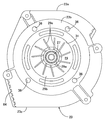
- FIG. 2 is a view taken in the direction of arrow 2 in FIG.
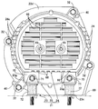
- FIG. 3 is a view taken in the direction of arrow 3 in FIG.
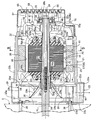
- First embodiment 4 is a cross-sectional view taken along line 4-4 of FIG.
- First embodiment 5 is a cross-sectional view taken along line 5-5 of FIG.
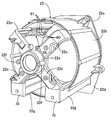
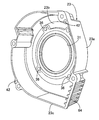
- First embodiment 6 is a perspective view of the first bracket.
- FIG. 7 is a perspective view of the second bracket.
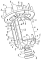
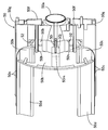
- FIG. 8 is a perspective view of the rotor and the cooling fan.
- (First embodiment) 9 is a cross-sectional view taken along line 9-9 of FIG. (First embodiment) FIG.
- FIG. 10 is a perspective view of the bobbin half.
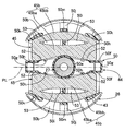
- (First embodiment) 11 is a cross-sectional view of the rotor taken along line 11-11 in FIG.
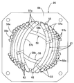
- FIG. 12 is a perspective view of the stator.
- FIG. 13 is a front view of one end of the stator as viewed from the direction along the axis of the rotating shaft.
- FIG. 14 is a view corresponding to FIG. 3 in a state in which a vibration-proof rubber is attached to the attachment portion.
- FIG. 15 is a view corresponding to FIG. 3 in a state in which a mounting leg is mounted on the mounting portion.
- FIG. 16 is a view corresponding to FIG. 3 in a state where the stay and the vibration-proof rubber are attached to the attachment portion by fastening together.
- the generator housing 21 is attached to the first bracket 22, the second bracket 23 coupled to the first bracket 22, and the first bracket 22 on the opposite side of the second bracket 23.
- the cover 24 is provided.
- a stator 25 is fixed to the first bracket 22 of the housing 21, and one end portion of the rotating shaft 27 is connected to the ball bearing 28 on the bearing portion 22 a of the first bracket 22.
- a rotor 26 that is rotatably supported through the stator 25 and is surrounded by the stator 25 is fixed to the rotary shaft 27, and a cooling fan 29 that rotates together with the rotary shaft 27 is covered with the second bracket 23.
- the first bracket 22 has a substantially cylindrical shape surrounding the bearing portion 22 a formed in a short cylindrical shape so as to fit the outer ring 28 a of the ball bearing 28 and the stator 25.
- the cylindrical portion 22b and one end of the cylindrical portion 22b are spaced apart in the circumferential direction of the bearing portion 22a, for example, four locations, and the other end is spaced in the circumferential direction of the one end portion of the cylindrical portion 22b.
- a retaining ring 30 for preventing axial movement of the ball bearing 28 in the bearing portion 22a is interposed.
- the second bracket 23 has a cylindrical side wall portion 23a whose one end is coupled to the cylindrical portion 22b of the first bracket 22, and a radius from the other end of the side wall portion 23a.
- An inward flange 23b projecting inward in the direction is integrally formed, and a circular opening 31 is formed on the inner periphery of the inward flange 23b.
- a flat outward flange 22d is integrally provided so as to protrude outward, and on the outer periphery of the outward flange 22d.
- a coupling protrusion 22e that slightly protrudes toward the second bracket 23 so as to abut one end of the side wall 23a is formed in one piece.
- the coupling protrusion 22e of the first bracket 22 is bolts 32, 32... Arranged at a plurality of locations spaced in the circumferential direction of the cylindrical portion 22b, and the side wall portion 23a of the second bracket 23.
- the second bracket 23 is attached to a drive source having a crankshaft 34 as a drive shaft connected coaxially to the rotary shaft 27, for example, an engine body 35 of the internal combustion engine E.
- the flange 23b is provided with a plurality of, for example, four fastening holes 36, 36,... Disposed around the opening 31, and the second bracket 23 has bolts 37, which are inserted into the fastening holes 36, 36,. 37... Are fastened to the engine body 35 at 37.
- the rotary shaft 27 has a tapered hole 38 at the end on the internal combustion engine E side, and is formed in a cylindrical shape.
- the rotary shaft 27 is inserted into the second bracket 23 through the opening 31.
- a tapered portion 34a at the end of the crankshaft 34 is fitted coaxially into the tapered hole 38, and a bolt 39 inserted into the rotating shaft 27 from the cover 24 side is screwed into the crankshaft 34 and tightened.
- the rotary shaft 27 is coaxially connected to the crankshaft 34 so as not to be relatively rotatable.
- the first bracket 22 is fastened to the engine body 35 in a state where the rotor 25 is fixed to a rotating shaft 27 to which the stator 25 is fixed and one end portion is rotatably supported by the bearing portion 22a.
- the two end portions of a plurality of, for example, two knock pins 40 for positioning the rotary shaft 27 and the crankshaft 34 to be aligned with each other. are provided in the coupling protrusion 22e of the first bracket 22 and the side wall 23a of the second bracket 23, respectively.
- the rotor 26 is formed by laminating a plurality of electromagnetic steel plates, and on a rotor core 43 fixed to the rotary shaft 27, a plane passing through the central axis of the rotary shaft 27.
- Field coils 45, 45 arranged on both sides of the PL are wound around a bobbin 44.
- One end of the rotating shaft 27 is press-fitted into an inner ring 28b of the ball bearing 28, and a pair of fields is provided on the outer periphery of a slip ring support 46 fixed to the rotating shaft 27 between the ball bearing 28 and the rotor 26.
- a pair of slip rings 47, 47 electrically connected to the magnetic coils 45, 45 are provided at intervals in the axial direction of the rotary shaft 27 and are supported by the first bracket 22 as shown in FIG. 4.
- a pair of brushes 49, 49 held by the brush holder 48 are in sliding contact with the slip rings 47, 47 individually.
- the bobbin 44 is attached to the rotor core 43 such that a pair of bobbin halves 50 and 50 formed in the same shape by a synthetic resin sandwich the rotor core 43 from both sides in a direction along the axis of the rotating shaft 27. Become.
- the bobbin half 50 includes a cylindrical support portion 50 a through which the rotation shaft 27 is inserted outside the rotor core 43 along the axis of the rotation shaft 27, and the rotation shaft 27.
- a pair of ends that are connected to both sides of the inner end of the cylindrical support portion 50a so as to extend along the one plane PL passing through the central axis, and that are opposed to and contact the outer end of the rotor core 43 along the axis of the rotary shaft 27.
- the plate portions 50b, 50b, and two ends of the end plate portions 50b are connected to the longitudinal ends on the one plane PL side.
- the inner side plate portions 50c, 50c,..., The outer side plate portions 50d, 50d, ... facing the inner side plate portions 50c, 50c, ..., and the inner side plate portions 50c, 50c, ... and the inner side plate portions 50d, 50d, ... are connected. Opening grooves 51, 51 ... are formed respectively by the bottom plate portions 50e, 50e ..., and two pairs of grooves 51, 51 ... which make a pair in the direction along the one plane PL are the bobbin half 50, that is, the bobbin. 44. Further, the inner regulating plate portions 50f, 50f are provided with flow holes 52, 52... Located on both sides of the cylindrical support portion 50a, and the flow holes 52, 52 are in a direction along the axis of the rotary shaft 27. Are formed integrally with the bobbin half 50.
- coil sides 45 a and 45 a of the field coil 45 are accommodated in the grooves 51 and 51 that form a pair in the direction along the one plane PL passing through the central axis of the rotating shaft 27.
- the coil end portions 45b and 45b at both ends of the field coil 45 are restricted from moving toward the one plane PL by the inner regulating plate portion 50f so as to connect the paired coil side portions 45a and 45a. It arrange
- the coil ends 45b and 45b of the field coil 45 are formed on the bobbin 44 at the portion corresponding to the outer end of the rotor core 43, as shown in FIG.
- Separating projections 50i, 50i are provided to divide the outer side portion 45ba ... and the outer side portion 45bb ..., and the inner projections are formed on both sides of the separating projections 50i, 50i along the circumferential direction of the rotary shaft 27.
- Gaps 53 are formed between the side portions 45ba and the outer side portions 45bb, respectively.
- the end plate portion 50b of the bobbin 44 has support bases 50j and 50j that protrude from the central portion in the longitudinal direction outward in the axial direction of the rotary shaft 27 and support the coil end portions 45b and 45b.
- the air passages 54 and 54 are formed between the coil end portions 45b and the end plate portions 50b on both sides of the support bases 50j and 50j along the circumferential direction of the rotary shaft 27, and are integrated with the end plate portion 50b.
- the separation protrusions 50i are projected from the support base 50j.
- air passages 54, 54 formed between the coil end portion 45 b and the end plate portion 50 b on both sides of the support base 50 j are formed at the outer ends along the radial direction of the rotating shaft 27 and the support base 50 j and
- the inner ends of the air passages 54, 54 that open to the outside of the rotor 26 through the space between the outer restricting protrusions 50 k, 50 k and extend along the radial direction of the rotating shaft 27 are provided in the inner restricting plate portion 50 f. It is opened to the outside of the rotor 26 at the outer end along the axial direction of the rotary shaft 27 through the flow holes 52.
- the stator 25 includes a plurality of output coils 57, 57... And a pair of stator coils 56, which are formed by laminating a plurality of electromagnetic steel plates and provided with a plurality of slots 55.
- the exciting coils 58 and 58 are wound.
- stator 25 is fixed to the first bracket 22 so as to be surrounded by the cylindrical portion 22b of the first bracket 22, and the cooling air sucked by the cooling fan 29 is the rotor 26.
- the stator 25 can be circulated between the outer periphery of the stator 25 and the inner periphery of the cylindrical portion 22b.
- a plurality of circumferential locations, for example, four locations on the outer periphery of the stator core 56 are press-fitted into the cylindrical portion 22b.
- the inner periphery of the cylindrical portion 22b is tapered with the second bracket 23 side as the maximum diameter in order to facilitate the insertion of the stator core 56 into the cylindrical portion 22b from the second bracket 23 side.
- the press-fit portions 59 for press-fitting the outer periphery of the stator core 56 are provided at four locations spaced in the circumferential direction of the intermediate portion of the cylindrical portion 22b.
- the press-fit portions 59 have the press-fit surfaces 60 extending along the axis of the rotary shaft 27 at the tip and extend in parallel to the direction along the axis of the rotary shaft 27. It is composed of two or three ridges 61, 61 ... projecting integrally on the inner surface of 22b, and between each of the ridges 61, 61 ... between the outer circumference of the stator 25 and the inner circumference of the cylindrical portion 22b.
- the cooling air can be circulated.
- the plurality of output coils 57, 57... And the pair of exciting coils 58, 58 are separated from each other in the circumferential direction of the stator core 56 with a plurality of slots 55, 55.
- a plurality of coil side portions 57a, 57a,... 58a, 58a,... Accommodated in 55, 55 are arranged outside the both axial ends of the stator core 56.
- stator core 56 is located on the inner side of the inner periphery of the stator core 56 when viewed from the direction along the axis of the rotary shaft 27.
- a plurality of coil end portions 57b, 57b,..., 58b, 58b connecting the two slots 55, 55 by shortcutting the plurality of conductors constituting the coil end portions 57b, 57b,. .., And the coil end portions 57b, 57b,... 58b, 58b that are dispersedly arranged so as to form an opening 62 that allows the rotation shaft 27 to pass therethrough at the center. are fixed to each other by varnish impregnation.
- the cooling fan 29 includes a cylindrical mounting tube portion 29 a that is fitted and fixed to the rotating shaft 27 in the second bracket 23, and the rotor 26.
- a taper tube portion 29b having a small diameter end connected to the mounting tube portion 29a so as to increase in diameter in the opposite direction, and a base end at a circumferentially spaced position on the outer periphery of the taper tube portion 29b Are formed in a ring shape so as to face the cooling fan 29 side end of the stator 25 and on the outer periphery of the plurality of blades 29c, 29c.
- a ring plate-like partition plate 29d provided in common is integrally provided, and a plurality of reinforcing ribs 29e, 29e,... Are integrally protruded from the inner periphery of the tapered cylindrical portion 29b.
- a discharge cylinder part 23c for discharging the cooling air discharged from the cooling fan 29 to the side is integrally provided at the lower part of the second bracket 23, and an outer end opening of the discharge cylinder part 23c is provided. Is provided with a louver 64 that divides the outer end opening into a plurality of sections.
- the cover 24 has a cylindrical side wall portion 24a and an end wall portion 24b that closes the outer end of the side wall portion 24a.
- the first bracket 22 is formed in a cylindrical shape and is fastened with bolts 65 and 65 to cylindrical boss portions 22f and 22f provided integrally on both sides of the bearing portion 22a in the first bracket 22. Fixed to.
- a plurality of first suction holes 66, 66... Opened downward are provided in the lower part of the side wall 24 a of the cover 24.
- a plurality of second suction holes 67 extending in the direction along the axis of the rotary shaft 27 are provided on both sides of the side wall portion 23a with a space therebetween in the vertical direction.
- 67... Are concealed in a side view, and flanges 24 c, 24 c... Projecting from the upper edges of the second suction holes 67, 67.
- the end wall portion 24b of the cover 24 is provided with a plurality of third suction holes 68, 68... By the operation of the cooling fan 29, and the first suction holes 66, 66. The cooling air is sucked into the housing 21 through the third suction holes 68, 68.
- one end portion of the first bracket 22, that is, the lower portion of the end portion on the cover 24 side, is a flat surface facing the cover 24 side so as to be disposed below the cover 24 when viewed from the cover 24 side.
- a pair of left and right mounting portions 22g, 22g having mounting surfaces 70, 70 are integrally provided.
- the mounting portions 22g and 22g are provided with a pair of vibration isolating rubbers 72, 72 for bolts 71, 72 for supporting the generator on the mount 69 via the vibration isolating rubbers 72, 72, for example.
- the mounting legs 73 are attached with a pair of bolts 71 and 71, and as shown in FIG.
- the state in which the stay 74 for mounting the exhaust muffler and the anti-vibration rubbers 72, 72 can be switched together by a pair of bolts 71, 71 can be switched, and the support legs of the generator can be made versatile. Can do.
- the first bracket 22 having a bearing portion 22a that pivotally supports one end of the rotating shaft 27, and the second bracket 23 that covers the cooling fan 29 that rotates together with the rotating shaft 27.
- a stator 25 is fixed to a housing 21 and a rotor 26 surrounded by the stator 25 is fixed to the rotary shaft 27.
- the stator 25 is fixed to the first bracket 22, and the cooling fan 29 is fixed.
- a cylindrical portion 22b surrounding the stator 25 is integrally provided so that the cooling air sucked in is circulated between the outer periphery of the stator 25, and the second bracket 23 is coupled to the cylindrical portion 22b. Therefore, cooling air is circulated along the outer periphery of the stator 25 to improve the cooling efficiency of the stator 25, and a long through bolt is used.
- the cost can be reduced so as to couple the first and second brackets 22 and 23 without Rukoto.
- stator 25 since a plurality of circumferential positions on the outer periphery of the stator 25 are press-fitted into the cylindrical portion 22b, the number of parts can be reduced when the stator 25 is fixed to the first bracket 22.
- the cooling fan 29 is provided with a ring-plate-shaped partition plate 29d facing the end of the stator 25 on the cooling fan 29 side, the circulation of the cooling air that has circulated along the outer periphery of the stator 25 By changing the direction to the rotating shaft 27 side at the end of the stator 25 on the cooling fan 29 side, the end of the stator 25 on the cooling fan 29 side can be effectively cooled with cooling air.
- the second bracket 23 fastened to the engine body 35 of the internal combustion engine E including the crankshaft 34 coaxially connected to the rotary shaft 27 and one end portion of the rotary shaft 27 are rotated by the bearing portion 22a of the first bracket 22.
- both ends of a plurality of knock pins 40 for positioning the shafts of the rotary shaft 27 and the crankshaft 34 together are fitted. Since the positioning holes 41..., 42... Are provided in the first and second brackets 22 and 23, respectively, the concave and convex fitting portions are not required as compared with the case where the first and second brackets 22 and 23 are fitted and positioned. Further, it is possible to further increase the cooling effect by increasing the outer diameter of the cooling fan 29 without increasing the outer shape of the second bracket 23.
- the rotor 26 has field coils 45, 45 arranged on both sides of a plane PL passing through the central axis of the rotary shaft 27 on a bobbin 44 attached to the rotor core 43 fixed to the rotary shaft 27.
- the bobbin 44 is configured to be wound and corresponds to the outer end of the rotor core 43 in the axial direction.
- the coil end portions 45b at both ends of the field coils 45 along the axial direction of the rotary shaft 27 are provided on the bobbin 44.
- 45b are separated into an inner portion 45ba along the radial direction of the rotary shaft 27 and an outer portion 45bb..., 45b, along the circumferential direction of the rotary shaft 27.
- gaps 53 are formed between the inner side portions 45ba and the outer side portions 45b on both sides of the separation protrusions 50i, respectively, the heat dissipation area of the coil end portion 45b of the field coil 45 is formed. Increases, the coil end portions 45b and thus the field coil 45 effectively cooled, thereby improving the power generation efficiency.
- the field plate is raised from the end plate portions 50b of the bobbin 44 so as to face and abut the outer end of the rotor core 43 in the axial direction of the rotary shaft 27 from the end plate portions 50b.
- a support base 50j for supporting the coil end portion 45b of the coil 45 is provided between the coil end portion 45b and the end plate portion 50b on both sides of the support base 50j along the circumferential direction of the rotary shaft 27.
- the separation protrusion 50i is provided on the support base 50j. Therefore, the heat dissipation area of the coil end portion 45b is further increased, and the coil end portion 45b is formed. As a result, the field coil 45 can be cooled more effectively, and the power generation efficiency can be further improved.
- a plurality of slots 55, 55... are provided on the inner periphery of the stator core 56 surrounding the rotor 26 fixed to the rotary shaft 27, and the plurality of slots 55, 55.
- a plurality of coil side portions 57a, 57a,... 58a, 58a,... Housed in slots 55, 55 spaced apart from each other are arranged on the outer sides in the axial direction of the stator core 56.
- a pair of exciting coils 58, 58 connected by 58 b, 58 b are wound around the stator core 56, and at one end side along the axial direction of the stator core 56, the rotating shaft A plurality of coils that connect the two slots in a shortcut manner inwardly of the inner periphery of the stator core 56 as viewed from the direction along the axis 27
- the end portions 57b, 57b,... 58b, 58b are dispersedly arranged so as to form an opening 62 allowing the insertion of the rotating shaft 27 at the center, so that the coil end portions 57b, 57b,.
- the amount of copper can be reduced by reducing the length of the coil, and the cooling effect by the cooling air flowing through the stator core 56 can be improved, and the heat dissipation of the coil end portions 57b, 57b,.
- the area can be increased and a more excellent cooling effect can be obtained.
Landscapes
- Engineering & Computer Science (AREA)
- Power Engineering (AREA)
- Motor Or Generator Cooling System (AREA)
- Iron Core Of Rotating Electric Machines (AREA)
- Windings For Motors And Generators (AREA)
- Synchronous Machinery (AREA)
Priority Applications (3)
| Application Number | Priority Date | Filing Date | Title |
|---|---|---|---|
| EP13841933.8A EP2903135A4 (en) | 2012-09-27 | 2013-09-26 | ROTOR FOR A GENERATOR |
| CN201380050411.5A CN104704713A (zh) | 2012-09-27 | 2013-09-26 | 发电机用转子 |
| US14/430,993 US20150270755A1 (en) | 2012-09-27 | 2013-09-26 | Rotor for generator |
Applications Claiming Priority (2)
| Application Number | Priority Date | Filing Date | Title |
|---|---|---|---|
| JP2012214187A JP5858364B2 (ja) | 2012-09-27 | 2012-09-27 | 発電機用ロータ |
| JP2012-214187 | 2012-09-27 |
Publications (1)
| Publication Number | Publication Date |
|---|---|
| WO2014050938A1 true WO2014050938A1 (ja) | 2014-04-03 |
Family
ID=50388333
Family Applications (1)
| Application Number | Title | Priority Date | Filing Date |
|---|---|---|---|
| PCT/JP2013/075999 Ceased WO2014050938A1 (ja) | 2012-09-27 | 2013-09-26 | 発電機用ロータ |
Country Status (5)
| Country | Link |
|---|---|
| US (1) | US20150270755A1 (https=) |
| EP (1) | EP2903135A4 (https=) |
| JP (1) | JP5858364B2 (https=) |
| CN (1) | CN104704713A (https=) |
| WO (1) | WO2014050938A1 (https=) |
Families Citing this family (3)
| Publication number | Priority date | Publication date | Assignee | Title |
|---|---|---|---|---|
| JP2020000669A (ja) * | 2018-06-29 | 2020-01-09 | 日本電産株式会社 | 送風装置 |
| DE102019112739A1 (de) | 2019-05-15 | 2020-11-19 | Bpw Bergische Achsen Kg | Elektrische Antriebseinheit für ein Kraftfahrzeug |
| JP7604286B2 (ja) * | 2021-03-19 | 2024-12-23 | 株式会社東芝 | 回転電機 |
Citations (3)
| Publication number | Priority date | Publication date | Assignee | Title |
|---|---|---|---|---|
| JPH0580148U (ja) | 1992-03-31 | 1993-10-29 | 澤藤電機株式会社 | 回転電機 |
| JP2000253607A (ja) * | 1999-03-01 | 2000-09-14 | Kokusan Denki Co Ltd | 回転電機用回転子 |
| JP2003235196A (ja) * | 2002-02-12 | 2003-08-22 | Kokusan Denki Co Ltd | 巻線用ボビン、回転電機用ロータ及び回転電機用ロータに対する含浸剤含浸方法 |
Family Cites Families (13)
| Publication number | Priority date | Publication date | Assignee | Title |
|---|---|---|---|---|
| GB190602151A (en) * | 1906-01-27 | 1907-01-10 | Charles Algernon Parsons | Improvements in Rotating Magnets for Dynamo Electric Machines. |
| DE649145C (de) * | 1935-01-18 | 1937-08-17 | Aeg | Kuehleinrichtung fuer die Spulenkoepfe gezahnter Laeufer elektrischer Maschinen |
| US3768152A (en) * | 1972-01-21 | 1973-10-30 | Dynamics Corp America | Method of making a motor stator |
| GB1449435A (en) * | 1974-03-22 | 1976-09-15 | Singer Co | Dynamo-electric machine rotors |
| JPS6268433U (https=) * | 1985-10-16 | 1987-04-28 | ||
| US5274292A (en) * | 1991-09-04 | 1993-12-28 | Onan Corporation | Collector ring assembly and method |
| JP3687479B2 (ja) * | 2000-04-07 | 2005-08-24 | 日立工機株式会社 | 整流子モータの固定子 |
| JP3871964B2 (ja) * | 2002-05-16 | 2007-01-24 | 三菱電機株式会社 | 回転電機の固定子鉄心の製造方法 |
| JP2005230932A (ja) * | 2004-02-17 | 2005-09-02 | Hitachi Koki Co Ltd | 電動工具 |
| US7262540B2 (en) * | 2004-02-26 | 2007-08-28 | Lg Electronics Inc. | Stator of outer rotor type motor for drum type washing machine |
| JP4496010B2 (ja) * | 2004-05-20 | 2010-07-07 | 株式会社東芝 | モータ |
| JP4533016B2 (ja) * | 2004-06-16 | 2010-08-25 | 日立工機株式会社 | 電動工具及び電動工具用固定子 |
| WO2008066216A2 (en) * | 2006-12-01 | 2008-06-05 | Lg Electronics Inc. | Motor |
-
2012
- 2012-09-27 JP JP2012214187A patent/JP5858364B2/ja not_active Expired - Fee Related
-
2013
- 2013-09-26 WO PCT/JP2013/075999 patent/WO2014050938A1/ja not_active Ceased
- 2013-09-26 US US14/430,993 patent/US20150270755A1/en not_active Abandoned
- 2013-09-26 CN CN201380050411.5A patent/CN104704713A/zh active Pending
- 2013-09-26 EP EP13841933.8A patent/EP2903135A4/en not_active Withdrawn
Patent Citations (3)
| Publication number | Priority date | Publication date | Assignee | Title |
|---|---|---|---|---|
| JPH0580148U (ja) | 1992-03-31 | 1993-10-29 | 澤藤電機株式会社 | 回転電機 |
| JP2000253607A (ja) * | 1999-03-01 | 2000-09-14 | Kokusan Denki Co Ltd | 回転電機用回転子 |
| JP2003235196A (ja) * | 2002-02-12 | 2003-08-22 | Kokusan Denki Co Ltd | 巻線用ボビン、回転電機用ロータ及び回転電機用ロータに対する含浸剤含浸方法 |
Non-Patent Citations (1)
| Title |
|---|
| See also references of EP2903135A4 |
Also Published As
| Publication number | Publication date |
|---|---|
| US20150270755A1 (en) | 2015-09-24 |
| EP2903135A4 (en) | 2016-08-10 |
| JP5858364B2 (ja) | 2016-02-10 |
| CN104704713A (zh) | 2015-06-10 |
| EP2903135A1 (en) | 2015-08-05 |
| JP2014068515A (ja) | 2014-04-17 |
Similar Documents
| Publication | Publication Date | Title |
|---|---|---|
| JP6016230B2 (ja) | 発電機 | |
| CN100473843C (zh) | 汽车发动机冷却风扇装置 | |
| US10594185B2 (en) | Rotor assembly and motor including same | |
| JP2008245356A (ja) | アキシャルギャップ型エンジン駆動発電機 | |
| RU2542744C2 (ru) | Электрическая машина для гибридных или электрических транспортных средств | |
| CN103052806A (zh) | 具有集成到叶轮风扇和鼓风机壳体构造的马达的鼓风机组件 | |
| JP2004120848A (ja) | アウタロータ型多極発電機 | |
| JP5858364B2 (ja) | 発電機用ロータ | |
| JP2012097583A (ja) | 電動ポンプ | |
| US11349370B2 (en) | Rotary electric machine with shrink-fitted bearing | |
| US20230066950A1 (en) | Motor and aircraft | |
| US8941279B2 (en) | Axial gap type generator | |
| KR101164588B1 (ko) | 터어보압축기 | |
| JP6037108B2 (ja) | 発電機におけるステータ構造 | |
| JP2015188279A (ja) | 発電機 | |
| CN104953764B (zh) | 轴向间隙型发电体的冷却构造 | |
| AU2014322794B2 (en) | An electric or hybrid vehicle using motor-generator having shaft with centrifugal fan blades for cooling | |
| JP5636064B2 (ja) | 電動ポンプ | |
| US9083211B2 (en) | Axial gap type generator | |
| JP2022062289A (ja) | 電動機及び電動送風機 | |
| US9071088B2 (en) | Axial gap type generator | |
| CN111971879B (zh) | 内燃机用旋转电机及其转子 | |
| KR200486068Y1 (ko) | 하우징 냉각구조 | |
| US12451782B2 (en) | Motor and aircraft | |
| KR20180034997A (ko) | 모터 |
Legal Events
| Date | Code | Title | Description |
|---|---|---|---|
| 121 | Ep: the epo has been informed by wipo that ep was designated in this application |
Ref document number: 13841933 Country of ref document: EP Kind code of ref document: A1 |
|
| WWE | Wipo information: entry into national phase |
Ref document number: 14430993 Country of ref document: US |
|
| NENP | Non-entry into the national phase |
Ref country code: DE |
|
| REEP | Request for entry into the european phase |
Ref document number: 2013841933 Country of ref document: EP |
|
| WWE | Wipo information: entry into national phase |
Ref document number: 2013841933 Country of ref document: EP |