WO2014050823A1 - シート電極 - Google Patents
シート電極 Download PDFInfo
- Publication number
- WO2014050823A1 WO2014050823A1 PCT/JP2013/075731 JP2013075731W WO2014050823A1 WO 2014050823 A1 WO2014050823 A1 WO 2014050823A1 JP 2013075731 W JP2013075731 W JP 2013075731W WO 2014050823 A1 WO2014050823 A1 WO 2014050823A1
- Authority
- WO
- WIPO (PCT)
- Prior art keywords
- electrode
- sheet electrode
- shape
- sheet
- face
- Prior art date
- Legal status (The legal status is an assumption and is not a legal conclusion. Google has not performed a legal analysis and makes no representation as to the accuracy of the status listed.)
- Ceased
Links
Images







Classifications
-
- A—HUMAN NECESSITIES
- A61—MEDICAL OR VETERINARY SCIENCE; HYGIENE
- A61N—ELECTROTHERAPY; MAGNETOTHERAPY; RADIATION THERAPY; ULTRASOUND THERAPY
- A61N1/00—Electrotherapy; Circuits therefor
- A61N1/18—Applying electric currents by contact electrodes
- A61N1/20—Applying electric currents by contact electrodes continuous direct currents
- A61N1/30—Apparatus for iontophoresis, i.e. transfer of media in ionic state by an electromotoric force into the body, or cataphoresis
-
- A—HUMAN NECESSITIES
- A61—MEDICAL OR VETERINARY SCIENCE; HYGIENE
- A61N—ELECTROTHERAPY; MAGNETOTHERAPY; RADIATION THERAPY; ULTRASOUND THERAPY
- A61N1/00—Electrotherapy; Circuits therefor
- A61N1/02—Details
- A61N1/04—Electrodes
- A61N1/0404—Electrodes for external use
- A61N1/0408—Use-related aspects
- A61N1/0428—Specially adapted for iontophoresis, e.g. AC, DC or including drug reservoirs
-
- A—HUMAN NECESSITIES
- A61—MEDICAL OR VETERINARY SCIENCE; HYGIENE
- A61N—ELECTROTHERAPY; MAGNETOTHERAPY; RADIATION THERAPY; ULTRASOUND THERAPY
- A61N1/00—Electrotherapy; Circuits therefor
- A61N1/02—Details
- A61N1/04—Electrodes
- A61N1/0404—Electrodes for external use
- A61N1/0472—Structure-related aspects
- A61N1/0492—Patch electrodes
Definitions
- One aspect of the present disclosure relates to a sheet electrode.
- the material that can be energized is applied in advance to the mask covering the face, for example, the electrode can not be freely moved to the place where the user wants to perform treatment.
- An object of the present disclosure is to provide a sheet electrode which performs a treatment through a mask conveniently.
- a sheet electrode for performing a treatment through a mask covering a predetermined region of a face, wherein the adhesive member makes the sheet electrode removable. And an electrode for supplying a signal for performing a treatment to a predetermined area of the face, wherein the electrode is configured in a shape corresponding to the uneven shape of the area for the treatment among the predetermined area of the face, the adhesive member A sheet electrode is provided, which is provided at an edge or an end of the electrode formed in a shape corresponding to the concavo-convex shape of the region where the treatment is performed.
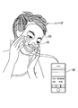
- FIG. 1 is a view showing an example of treatment using the sheet electrode according to the present embodiment.
- the sheet electrode 10 is provided on a face mask 20 covering a predetermined area of the face of a user (for example, a treated person) and outputs a signal (for example, a signal for treatment) for performing treatment. It is connected to the output device 30.
- an active component contained in the face mask 20 is generated by a weak current (for example, about 10 ⁇ A to 1 mA) flowing to the sheet electrode 10. It will penetrate the skin of the user.
- the sheet electrode 10 As described above, by using the sheet electrode 10, it is possible to perform the treatment for the user through, for example, the face mask 20.
- the sheet electrode 10 is, for example, integrated with an adhesive member to be attachable to and detachable from the face mask 20, an electrode to which a signal for performing a treatment is supplied from the output device 30, and the like.
- the face mask 20 is, for example, a face mask formed of a non-woven fabric or the like having water retention and water resistance, and may be, for example, a facial care mask used commercially.
- the face mask 20 is, for example, one or more active ingredients contained in at least one of medicine, medicine, and cosmetics (for example, lotion, milk, cream, gel, etc.), for example, vitamin C for activating the skin and the like Derivatives, tranexamic acid, 4-methoxysalicylic acid and salts thereof, water-soluble active ingredients such as lidocaine and diphenhydramine, etc. are impregnated.
- medicine, medicine, and cosmetics for example, lotion, milk, cream, gel, etc.
- vitamin C for activating the skin and the like
- Derivatives, tranexamic acid, 4-methoxysalicylic acid and salts thereof, water-soluble active ingredients such as lidocaine and diphenhydramine, etc. are impregnated.
- the output device 30 is in widespread use, for example, in smartphones, mobile phones, tablet terminals, PDAs (Personal Data Assistants), PDs (Portable Devices such as iPods (registered trademark)), PCs (Personal Computers), game machines, etc. It may be a content reproduction device, as long as it is a device that outputs a signal for performing operations such as ion introduction.
- PDAs Personal Data Assistants
- PDs Portable Devices such as iPods (registered trademark)
- PCs Personal Computers
- game machines etc. It may be a content reproduction device, as long as it is a device that outputs a signal for performing operations such as ion introduction.
- the sheet electrode 10 can be freely attached to the portion on the face mask 20 where the operation is desired, and the operation can be repeated using the same sheet electrode 10. Therefore, according to the sheet electrode 10, it becomes possible to perform treatment via the mask with high convenience.
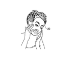
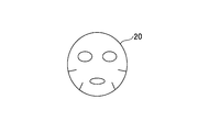
- FIG. 2A and 2B are diagrams showing an example of a face mask provided with the sheet electrode according to the present embodiment.
- FIG. 2A shows the face mask 20 covering the user's face
- FIG. 2B shows a plan view of the face mask 20.
- the face mask 20 when performing treatment using the sheet electrode 10, for example, the face mask 20 is put on the face, and for example, the active ingredient impregnated in the face mask 20 is attached to the entire face of the user.
- the face mask 20 is formed, for example, in accordance with the shape of the user's face, and an opening is formed in a portion corresponding to the user's eyes, mouth, nose, etc., for example.
- the face mask 20 described above has, for example, a shape that covers the entire face, but is not limited to this.
- it may be a shape that covers only the region such as the eyes and cheeks where treatment is desired.
- FIG. 3A to 3C are diagrams for explaining the sheet electrode according to the present embodiment.
- FIG. 3A shows a plan view of the back surface of the sheet electrode 10
- FIG. 3B shows a plan view of the surface of the sheet electrode 10.
- FIG. 3C is a cross-sectional view taken along the line I-II in FIG. 3A.
- an electrode 11 As shown in FIG. 3A, on the back surface of the sheet electrode 10, an electrode 11, an adhesion member 12, and a hook-type electrode terminal 13 are provided.
- the electrode 11 is supplied with a signal for performing a treatment from the output device 30 via, for example, the hook-type electrode terminal 13.
- the electrode 11 is made of, for example, carbon or the like, but may be made of aluminum, stainless steel, platinum, Ag / AgCl, or the like.
- the shape of the electrode 11 may be, for example, sheet-like (planar) or mesh-like.
- the adhesive member 12 allows the sheet electrode 10 to be detachable from, for example, the face mask 20 impregnated with the active ingredient.
- the bonding member 12 is formed of, for example, a surface fastener or the like, but is not limited to this.
- the adhesive member 12 functions as a hook side, for example, when it is configured by a surface fastener, and the face mask 20 functions as a loop side to stick or peel the electrode 11 to or from the face mask 20. It becomes possible.
- the hook type electrode terminal 13 is provided, for example, such that the front side and the back side of the sheet electrode 10 communicate with each other. For example, by connecting the hook type electrode terminal 13 to the connector portion of the output cord, the output device 30 and the electrode 11 are electrically connected.
- a mount 14 is provided on the surface of the sheet electrode 10, and a hook portion of the hook-type electrode terminal 13 for connecting to the connector portion of the output cord appears.
- the backing sheet 14 is used, for example, to integrate the electrode 11, the bonding member 12, and the hook-type electrode terminal 13.
- the backing sheet 14 is made of, for example, a film method synthetic paper (for example, Yupo (registered trademark) FPG-60 (60 ⁇ m in thickness)) whose main raw material is polypropylene or the like, for example. It is preferable to use one that has water resistance that can be repeatedly used, and flexibility to be in close contact with the face.
- the mount 14 may have, for example, stretchability.
- the sheet electrode 10 is bonded to the backing 14 so that the electrode 11 and the bonding member 12 face the face mask 20 respectively. Further, the hook type electrode terminal 13 is provided so as to connect the electrode 11 and the backing sheet 14.
- the hook-type electrode terminal 13 on the mount 14 side be provided in a state connectable to the connector portion of the output cord 31 of the output device 30.
- the hook-type electrode terminal 13 on the electrode 11 side may be configured to be covered with, for example, a seal-like mounting sheet 15 or the like, and may be embedded in the electrode 11, for example. It is good.
- the adhesive members 12 are provided at the edge on the backing sheet 14 and the electrodes 11 are provided between the adhesive members 12 (central region of the backing sheet 14).
- the electrode 11 may be provided up to the edge on 14 (for example, in the same size as the backing sheet 14 and entirely overlapped), and the bonding member 12 may be provided on the edge on the electrode 11.
- the electrode 11 and the adhesive member may be configured to face the face mask 20, for example.
- the sheet electrode 10 is formed so that the electrode 11, the bonding member 12 and the hook type electrode terminal 13 are integrated by the backing sheet 14.
- the sheet electrode 10 since it is detachable with respect to the face mask 20, it becomes possible to operate to the location which a user wants to operate via the face mask 20. FIG. In addition, since the same sheet electrode 10 can be used repeatedly, even after using the face mask 20, it can be used for the operation as many times as possible by replacing it with a new face mask 20. Thus, according to the sheet electrode 10, it is possible to perform treatment through the mask with high convenience.
- FIG. 4 is a view for explaining an adhesive member of the sheet electrode according to the present embodiment.
- 4A shows an example of the bonding member 12
- FIG. 4B shows an example of the electrode 11
- FIG. 4C shows an example of the backing sheet 14. As shown in FIG.
- the sheet electrode 10 is configured, for example, by providing the bonding member 12 shown in FIG. 4A and the electrode 11 shown in FIG. 4B on a mount 14 shown in FIG.
- the shape of the bonding member 12 is a shape along the circular edge of the electrode 11 shown in FIG. 4B, but is not limited thereto.
- the bonding member 12 may be shaped so as not to peel off and adhere when the sheet electrode 10 is attached to the face mask 20.
- the electrode 11 and the bonding member 12 may be bonded to the backing sheet 14 using, for example, acrylic glue or heat welding.
- the electrode 11 may be made of the above-described conductive material such as carbon, and provided on the mount 14 by, for example, printing or coating.
- 5A to 5D are diagrams for explaining the shape of the sheet electrode and the attachment position of the adhesive member.
- 5A and 5B respectively show an example of the shape of the sheet electrode 10 and the attachment position of the adhesive member.
- 5C and 5D are diagrams for explaining the shape of the sheet electrode 10 in the present embodiment.
- the sheet electrode 10 is used by being attached, for example, on the face mask 20, but the user's face has a concavo-convex shape (e.g., a curved face shape is also included). Areas (treatment areas) such as certain eyes and cheeks also have the respective uneven shapes. In addition, the uneven shape of the face also differs depending on the user.
- the sheet electrode 10 in the present embodiment when used by being attached to, for example, the face mask 20, the sheet electrode 10 is configured to be in a close contact state, for example, so as not to include a void in the shape of the user's face. It is good.
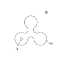
- the diameter 16 of the largest circle 40 provided so as to be inscribed in the outer periphery of the sheet electrode 10 is, for example, a predetermined length (for example, about 1 cm to 3 cm) Good to configure.
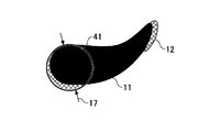
- the sheet electrode 10 may be configured such that the diameter 17 of the largest circle 41 provided to be inscribed in the outer periphery of the shape is, for example, a predetermined length.
- the sheet electrode 10 is configured to conform to, for example, the uneven shape of the face of the user by setting the diameter of the largest circle provided to be inscribed in the outer periphery of the shape to a predetermined length, for example. It is possible to In addition, the shape of the sheet electrode 10 may be configured so as not to include a void due to a wrinkle or the like of the electrode 11 which occurs because the shape does not follow the uneven shape of the face.
- the diameter of the largest circle provided so as to be inscribed in the outer periphery of the shape of the sheet electrode 10 may be appropriately changed to, for example, 0.5 cm to 4 cm. And the shape of the treatment area).
- the bonding member 12 is attached to the circular edge or end of the electrode 11.
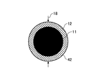
- the diameter 18 of the circle 42 provided to be inscribed in the outer periphery of the shape of the sheet electrode 10 exceeds the above-described predetermined length.
- the sheet electrode 10 does not follow the uneven shape of the face and the adhesive member 12 is attached to the periphery of the electrode 11, there is a void when it is attached to the face mask 20.
- At least one hole may be provided in a part of the entire shape of the sheet electrode 10 to provide a portion that does not closely contact the shape of the face, for example.
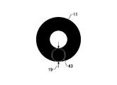
- one hole is provided in the central region of the electrode 11 in the example of FIG. 5D, the present invention is not limited to this.
- the diameter of a circle 43 provided so as to be inscribed in the outer periphery of the shape of the sheet electrode 10 can be configured to have a predetermined length.
- the sheet electrode 10 is configured to conform to the uneven shape of the face by, for example, configuring the diameter of the largest circle provided to be inscribed in the outer periphery of the shape to be a predetermined length. Is possible. Thereby, the close contact state of the sheet electrode 10 when attached to the face mask 20 is improved, and it becomes possible to perform the operation in the state in which the sheet electrode 10 is in close contact.
- FIGS. 6A to 6H are diagrams showing an example of the shape of the sheet electrode corresponding to the treatment area.
- the diameter of the largest circle provided so as to be inscribed in the outer periphery of the shape described in FIGS. 5A to 5D is a predetermined length, Explain the shape.
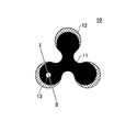
- FIG. 6A shows an example of a sheet electrode 10 having three circular shapes
- FIG. 6B shows an example of a sheet electrode having four circular shapes
- FIG. 6C shows a sheet having rectangular rectangular ends.
- An example of the electrode 10 is shown.
- 6D shows an example of the sheet electrode 10 having a circular shape as a whole
- FIG. 6E shows an example of the sheet electrode 10 having a circular shape at one end shown in FIG.
- FIG. 6F shows an example of the sheet electrode 10 in which three circular shapes are connected in a rectangular shape.
- FIG. 6G shows an example of the sheet electrode 10 of "tsu" shape
- FIG. 6H shows an example of the sheet electrode 10 of umbrella shape.
- the sheet electrode 10 shown in FIGS. 6A and 6B has, for example, a shape used when performing surgery on an area of the user's face, for example, from the eyes or from the eyes to the cheek.
- a shape used when performing surgery on an area of the user's face for example, from the eyes or from the eyes to the cheek.
- the uneven shape of the region extending from the eyes and eyes to the cheek is relatively small among the uneven shapes of the face, the height difference of the uneven shape is relatively small, but the range having a gentle curved surface is wide.
- a plurality of circular shapes having the above-described diameter of a predetermined length for example, a shape that can be configured in a mesh shape, can be attached along the shape of the face.
- a close contact it is possible to obtain a close contact.
- the sheet electrode 10 shown in FIG. 6C has a shape used when performing treatment on the forehead, for example, the cheek, the jaw, the nose, etc. in the region of the face, and the sheet electrode 10 shown in FIG.
- the forehead, the cheek, the jaw, etc. have a shape used when performing the treatment.
- the shape of the sheet electrode 10 shown in FIGS. 6C and 6D is smaller in the number of circular shapes having the diameter of the above-described predetermined length than the shape of the sheet electrode 10 shown in FIGS. 6A and 6B described above.
- the sheet electrode 10 shown in FIG. 6C having a shape along the concavo-convex shape, for example, for a nose having a large unevenness difference and a wide range having the concavo-convex shape.
- the sheet electrode 10 shown to FIG. 6E has a shape used, for example, when performing treatment with respect to eyes and a cheek among the area
- the sheet electrode 10 shown to FIG. For example, it has a shape used when performing surgery on eyes, cheeks, jaws, and the like.
- the sheet electrode 10 shown in FIG. 6E has, for example, a shape along the eye or cheek area
- the sheet electrode 10 shown in FIG. 6F has, for example, a shape along not only the eye or cheek area but also the jaw area have. Therefore, since it adheres along the uneven
- the sheet electrode 10 shown in FIG. 6G has, for example, a shape used when performing surgery on the corner of the face in the region of the face, and the sheet electrode 10 shown in FIG. It has a shape used when performing treatment in the area of
- the sheet electrode 10 shown in FIG. 6G similarly has, for example, a shape along the region of the edge of the eye
- the sheet electrode 10 shown in FIG. 6F similarly has, for example, the shape along the region of the nose There is. Therefore, since it adheres along the uneven
- the sheet electrode 10 described above while the diameter of the largest circle provided so as to be inscribed in the outer periphery of the shape described in FIGS. 5A to 5D is a predetermined length, the shape along the uneven shape of each treatment area By having the above, it is possible not to include a void for each shape, and it is possible to obtain a close contact state.
- the shape of the bonding member 12 shown in FIGS. 6A to 6H is a shape along the circular edge or end of the electrode 11 as described above, but the sheet electrode 10 is attached to the face mask 20 It may be shaped so as not to come off and adhere when attached.
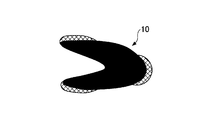
- FIG. 7A shows an example of a sheet electrode 10 having a shape corresponding to, for example, the area of the nose.
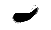
- FIG. 7B shows an example of the sheet electrode 10 which has a shape corresponding to area
- the sheet electrode 10 shown to FIG. 7A has shown an example of the surface of the sheet electrode 10 shown to FIG. 6H mentioned above.
- the uneven shape of the nose region has, for example, a large difference in height between the uneven shape and a wide range of the uneven shape as compared with the uneven shape of the other region of the face.
- the holding member 44 for holding the deformed state is used. It is good to provide.
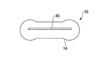
- the sheet electrode 10 shown to FIG. 7B has shown an example of the surface of the sheet electrode 10 shown to FIG. 6C mentioned above.
- the nose area for example, the area of the jaw or the like has a height difference of the uneven shape, and the range of the uneven shape is wide.
- the holding member 45 for holding the deformed state is used. It is good to
- the holding member 44 and the holding member 45 described above use, for example, resin wire (for example, Technoroto (registered trademark) of Mitsui Chemical Co., Ltd., etc.), but not limited to this, in order to hold a plastically deformed state It is sufficient if it is a member having the material of. Further, the holding member 44 and the holding member 45 may be adhered to the backing 14 using, for example, acrylic glue or heat welding, or may be attached to the backing 14 using a sealing backing. , May be sewn to the backing sheet 14.
- resin wire for example, Technoroto (registered trademark) of Mitsui Chemical Co., Ltd., etc.
- the holding member 44 and the holding member 45 may be provided at a portion that is most deformed when the sheet electrode 10 is plastically deformed so as to be in close contact with the treatment area, for example. .
- the sheet electrode 10 having the holding member 44 and the holding member 45 it is possible to hold the plastically deformed state, so the sheet electrode for the shape of the face through the face mask 20 It is possible to improve the adhesion strength of 10.
- the sheet electrode 10 may be made of a material (material) that holds the plastically deformed state. good.
- the sheet electrode is provided to perform the treatment through the mask.
- a sheet electrode is used for the face
- the present invention is not limited to this.
- the sheet electrode can be applied to cosmetic treatment such as microcurrent (weak current therapy), EMS (Electrical Muscle Stimulation), low frequency treatment, etc. Or it is possible to use for other treatment.
Landscapes
- Health & Medical Sciences (AREA)
- Engineering & Computer Science (AREA)
- Biomedical Technology (AREA)
- Nuclear Medicine, Radiotherapy & Molecular Imaging (AREA)
- Radiology & Medical Imaging (AREA)
- Life Sciences & Earth Sciences (AREA)
- Animal Behavior & Ethology (AREA)
- General Health & Medical Sciences (AREA)
- Public Health (AREA)
- Veterinary Medicine (AREA)
- Bioinformatics & Cheminformatics (AREA)
- Electrotherapy Devices (AREA)
Description
本開示の一側面は、シート電極に関する。
従来では、皮膚に微弱な電流を流すことで、例えば水溶性の有効成分を皮膚内に効果的に導入するイオン導入法等の施術が知られている。また、顔面を覆うマスクに通電可能な物質を塗布しイオン導入器の電極導子と接続可能とすることで、顔面マスクを用いてイオン導入を行う手法が知られている(例えば、特許文献1参照)。
しかしながら、上述したような従来手法では、顔面を覆うマスクに予め通電可能な物質が塗布されているため、例えばユーザが施術を行いたい箇所に電極を自由に移動させることができなかった。また、通電可能な物質が塗布されている専用のマスクを使用する必要があり、例えば市販のマスクを用いて繰り返し施術を行うことができなかった。
本開示は、利便性良くマスクを介して施術を行うシート電極を提供することを1つの目的とする。
本開示の一側面によれば、顔面の所定の領域を被覆するマスクを介して施術を行うためのシート電極であって、前記マスクに対して、当該シート電極を着脱可能とする接着部材と、前記顔面の所定の領域に施術を行う信号を供給する電極とを有し、前記電極は、前記顔面の所定の領域のうち施術を行う領域の凹凸形状に対応する形状で構成され、前記接着部材は、前記施術を行う領域の凹凸形状に対応する形状で構成された前記電極の縁部又は端部に設けられることを特徴とするシート電極が提供される。
本開示の一側面によれば、利便性良くマスクを介して施術を行うシート電極を提供することが可能となる。
以下、実施の形態について詳細に説明する。
<シート電極を用いた施術例>
図1は、本実施形態に係るシート電極を用いた施術の一例を示す図である。図1の例では、シート電極10は、ユーザ(例えば被施術者等)の顔面の所定の領域を被覆する顔面マスク20上に設けられ、施術を行う信号(例えば、施術用信号)を出力する出力装置30に接続される。
図1は、本実施形態に係るシート電極を用いた施術の一例を示す図である。図1の例では、シート電極10は、ユーザ(例えば被施術者等)の顔面の所定の領域を被覆する顔面マスク20上に設けられ、施術を行う信号(例えば、施術用信号)を出力する出力装置30に接続される。
シート電極10に出力装置30から施術を行う信号が供給されると、例えばイオン導入の場合には、シート電極10に流れる微弱電流(例えば10μA~1mA程度)により顔面マスク20に含まれる有効成分がユーザの皮膚に浸透していくこととなる。
このように、シート電極10を用いることにより、例えば顔面マスク20を介してユーザに施術を行うことが可能となる。
シート電極10は、例えば顔面マスク20に対して着脱可能となるための接着部材や出力装置30から施術を行う信号が供給される電極等が一体化されている。
顔面マスク20は、例えば保水性や耐水性を有する不織布等により成形された顔面用マスクであり、例えば市販で使用される美顔用マスク等であっても良い。
顔面マスク20は、例えば薬剤、医薬品、及び化粧品(例えば化粧水、乳液、クリーム、ゲル等)のうち少なくとも1つに含まれる1又は複数の有効成分、例えば、皮膚を活性化させるビタミンC及びその誘導体、トラネキサム酸、4メトキシサリチル酸及びその塩、リドカイン、ジフェンヒドラミン等の水溶性の有効成分等が含浸している。
出力装置30は、例えばスマートフォン、携帯電話、タブレット端末、PDA(Personal Data Assistant)、例えばiPod(登録商標)等のPD(Portable Device)、PC(Personal Computer)、ゲーム機等の一般に普及しているコンテンツ再生装置であっても良く、イオン導入等の施術を行う信号を出力する装置であれば良い。
上述した構成により、顔面マスク20上の施術したい箇所にシート電極10を自由に取り付けることが可能となり、更に同一のシート電極10を用いて繰り返し施術を行うことが可能となる。したがって、シート電極10によれば、利便性良くマスクを介して施術を行うことが可能となる。
<顔面マスク20>
図2A及び2Bは、本実施形態に係るシート電極が設けられる顔面マスクの一例を示す図である。図2Aは、顔面マスク20がユーザの顔面を覆った状態を示し、図2Bは、顔面マスク20の平面図を示している。
図2A及び2Bは、本実施形態に係るシート電極が設けられる顔面マスクの一例を示す図である。図2Aは、顔面マスク20がユーザの顔面を覆った状態を示し、図2Bは、顔面マスク20の平面図を示している。
図2Aに示すように、シート電極10を用いて施術を行う場合には、例えば顔面マスク20を顔面に被せ、例えば顔面マスク20に含浸した有効成分をユーザの顔面全体に付着した状態とする。
図2Bに示すように、顔面マスク20は、例えばユーザの顔面の形状に合わせて成形され、例えばユーザの目や口、鼻等に対応する部分に開口部が形成されている。
上述した顔面マスク20は、例えば、顔面全体を覆う形状としているがこれには限定されず、例えば施術を行いたい目元や頬等の領域のみ覆う形状としても良い。
<シート電極10の構成>
図3A~3Cは、本実施形態に係るシート電極を説明するための図である。図3Aは、シート電極10の裏面の平面図を示し、図3Bは、シート電極10の表面の平面図を示す。また、図3Cは、図3AのI-IIに示す線上で切断したときの断面図を示す。
図3A~3Cは、本実施形態に係るシート電極を説明するための図である。図3Aは、シート電極10の裏面の平面図を示し、図3Bは、シート電極10の表面の平面図を示す。また、図3Cは、図3AのI-IIに示す線上で切断したときの断面図を示す。
図3Aに示すように、シート電極10の裏面には、電極11と、接着部材12と、ホック式電極端子13とが設けられている。
電極11は、例えばホック式電極端子13を介して出力装置30から施術を行う信号が供給される。電極11は、例えばカーボン等により構成されるが、アルミニウム、ステンレス、白金、Ag/AgCl等により構成されても良い。また、電極11の形状は、例えばシート状(面状)やメッシュ状により構成されると良い。
接着部材12は、例えば有効成分が含浸した顔面マスク20に対してシート電極10を着脱可能な状態とする。接着部材12は、例えば面ファスナー等により構成されるが、これに限定されるものではない。
接着部材12は、例えば面ファスナーにより構成される場合にはフック側として機能し、顔面マスク20がループ側として機能することで、顔面マスク20に対して電極11を貼り付けたり剥がしたりすることが可能となる。
ホック式電極端子13は、例えばシート電極10の表面側と裏面側とが連通するように設けられる。例えば、ホック式電極端子13が出力コードのコネクタ部と接続されることにより、出力装置30と電極11とを電気的に接続する。
また、図3Bに示すように、シート電極10の表面には、例えば台紙14が設けられ、出力コードのコネクタ部と接続するためのホック式電極端子13のホック部分が現れている。
台紙14は、例えば電極11と接着部材12とホック式電極端子13とを一体化するために用いられる。
台紙14は、例えばポリプロピレン等を主原料とするフィルム法合成紙(例えばユポ(登録商標)FPG-60(厚さ60μm))等により構成されるが、例えば紙に限定されるものではなく、例えば繰り返し使用可能な耐水性や、顔面に密着する柔軟性を有するものを用いると良い。また、台紙14は、例えば伸縮性を有していても良い。
また、図3Cに示すように、シート電極10は、顔面マスク20に対して、電極11と接着部材12とがそれぞれ対面するように台紙14に接着されている。また、ホック式電極端子13は、電極11及び台紙14を連通するように設けられている。
すなわち、台紙14側のホック式電極端子13は、出力装置30の出力コード31のコネクタ部と接続可能な状態に設けられると良い。また、電極11側のホック式電極端子13は、例えばシール状の台紙15等により覆うように構成されても良く、例えば電極11に埋め込まれても良く、電極11と連通可能な状態に設けられると良い。
なお、図3Cの例では、台紙14上の縁部に接着部材12を設け、接着部材12の間(台紙14の中央領域)に電極11を設けているがこれには限定されず、例えば台紙14上の縁部まで(例えば台紙14と同じサイズで全体に重なるように)電極11を設け、電極11上の縁部に接着部材12を設けても良い。このように、電極11と接着部材とは、例えば顔面マスク20に対面するように構成されれば良い。
上述したように、シート電極10は、電極11と接着部材12とホック式電極端子13とが台紙14により一体化されるよう形成されている。
また、シート電極10によれば、顔面マスク20に対して着脱可能であるため、顔面マスク20を介してユーザの施術したい箇所に施術することが可能となる。また、同一のシート電極10は繰り返し使用可能であるため、顔面マスク20を使用した後も新たな顔面マスク20に取り替えることで何度でも施術に用いることが可能となる。このように、シート電極10によれば、利便性良くマスクを介して施術を行うことが可能となる。
<接着部材12>
図4は、本実施形態に係るシート電極の接着部材について説明するための図である。図4(A)は、接着部材12の一例を示し、図4(B)は、電極11の一例を示し、図4(C)は、台紙14の一例を示す。
図4は、本実施形態に係るシート電極の接着部材について説明するための図である。図4(A)は、接着部材12の一例を示し、図4(B)は、電極11の一例を示し、図4(C)は、台紙14の一例を示す。
シート電極10は、例えば、図4(A)に示す接着部材12と、図4(B)に示す電極11とを、図4(C)に示す台紙14上に設けることで構成される。
図4(A)に示すように、接着部材12の形状は、図4(B)に示す電極11の円状の縁部に沿った形状とするがこれには限定されない。例えば、接着部材12は、顔面マスク20に対してシート電極10を貼り付けたときに剥がれず、密着するような形状にすれば良い。
ここで、電極11及び接着部材12はそれぞれ、台紙14に対して例えばアクリル製の糊や熱溶着等を用いて接着させると良い。また、電極11は、上述したカーボン等による導電性物質により構成して、台紙14上に、例えば印刷や塗布等により設けても良い。
<シート電極10の形状と接着部材12の取付位置>
図5A~5Dは、シート電極の形状及び接着部材の取付位置を説明するための図である。なお、図5A、図5Bは、それぞれシート電極10の形状及び接着部材の取付位置の一例を示している。また、図5C、図5Dは、本実施形態におけるシート電極10の形状について説明するための図である。
図5A~5Dは、シート電極の形状及び接着部材の取付位置を説明するための図である。なお、図5A、図5Bは、それぞれシート電極10の形状及び接着部材の取付位置の一例を示している。また、図5C、図5Dは、本実施形態におけるシート電極10の形状について説明するための図である。
上述したように、シート電極10は、例えば顔面マスク20上に貼り付けて用いられるが、ユーザの顔面は凹凸形状(例えば、曲面の顔形状も含まれる)を有し、施術を行いたい箇所である目元や頬等の領域(施術領域)もそれぞれの凹凸形状を有している。また、ユーザごとに、顔面の凹凸形状もそれぞれ異なる。
そこで、本実施形態におけるシート電極10は、例えば顔面マスク20上に貼り付けて用いるときに、例えばユーザの顔面の形状に対して空隙を含まないように、例えば密着した状態となる形状に構成されると良い。
例えば、図5Aの例では、シート電極10は、その形状の外周に内接するように設けられた最大の円40の直径16が、例えば所定の長さ(例えば、約1cm~3cm等)となるように構成すると良い。
また、図5Bの例では、シート電極10は、その形状の外周に内接するように設けられた最大の円41の直径17が、例えば所定の長さとなるように構成すれば良い。
上述のように、シート電極10は、例えば形状の外周に内接するように設けられた最大の円の直径を所定の長さとすることで、例えばユーザの顔の凹凸形状に沿うように形状を構成することが可能となる。なお、シート電極10の形状は、顔の凹凸形状に沿わないために生じる電極11のシワ等による空隙が含まれないように構成すれば良い。
したがって、シート電極10は、例えばその形状の外周に内接するように設けられた最大の円の直径を、例えば0.5cm~4cm等のように適宜変更しても良く、顔の凹凸形状(例えば、施術領域の形状)に沿うように構成すれば良い。
図5Aや図5Bの例では、接着部材12は、電極11の円状の縁部や端部に取り付けられている。
ここで、例えば図5Cの例では、シート電極10は、その形状の外周に内接するように設けられた円42の直径18が、上述した所定の長さを超えている。このような形状の場合、シート電極10が顔の凹凸形状に追従しなくなり、接着部材12が電極11の周囲に取り付けられているにもかかわらず、顔面マスク20に貼り付けたときに空隙を有してしまう可能性がある。
そこで、本実施形態では、例えば図5Dに示すように、例えばシート電極10の全体形状の一部に少なくとも1つの穴を設けて、例えば顔面の形状と密着しなくて良い部分を設けると良い。なお、図5Dの例では、電極11の中央領域に穴を1つ設けているが、これに限定されるものではない。これにより、例えばシート電極10の形状の外周に内接するように設けられた円43の直径を所定の長さとなるように構成することが可能となる。
上述したように、シート電極10は、例えば形状の外周に内接するように設けられた最大の円の直径を所定の長さとなるように構成することで、顔の凹凸形状と沿うよう構成することが可能となる。これにより、顔面マスク20に貼り付けたときのシート電極10の密着状態を向上させ、シート電極10が密着した状態で施術することが可能となる。
<施術領域に対応したシート電極10の形状例>
図6A~6Hは、施術領域に対応したシート電極の形状の一例を示す図である。なお、図6A~6Hの例では、例えば図5A~5Dで説明した形状の外周に内接するように設けられた最大の円の直径を所定の長さとしながら、施術領域に対応したシート電極10の形状を説明する。
図6A~6Hは、施術領域に対応したシート電極の形状の一例を示す図である。なお、図6A~6Hの例では、例えば図5A~5Dで説明した形状の外周に内接するように設けられた最大の円の直径を所定の長さとしながら、施術領域に対応したシート電極10の形状を説明する。
図6Aは、3つの円状を有したシート電極10の一例を示し、図6Bは、4つの円状を有したシート電極の一例を示し、図6Cは、矩形の両端を円状にしたシート電極10の一例を示す。また、図6Dは、全体が円状のシート電極10の一例を示し、図6Eは、図6Cに示す一端を円状として、他端に向けて径を小さくしたシート電極10の一例を示し、図6Fは、3つの円状を矩形状に接続したシート電極10の一例を示す。また、図6Gは、「つ」状のシート電極10の一例を示し、図6Hは、傘状のシート電極10の一例を示す。
図6Aや図6Bに示すシート電極10は、例えばユーザの顔面の領域のうち、例えば目元や目元から頬にかかる領域に対して施術を行うときに用いる形状を有している。例えば、目元や目元から頬にかかる領域の凹凸形状は、顔面の凹凸形状のうち凹凸形状の高低差は比較的小さいが、なだらかな曲面を有する範囲が広い。
そこで、図6Aや図6Bに示すように、上述した所定の長さの直径を有する円状を複数有する、例えばメッシュ状に構成可能な形状とすることで、顔面の形状に沿うように貼り付けられるため、密着した状態を得ることが可能となる。
また、図6Cに示すシート電極10は、顔面の領域のうち額や、例えば頬や顎、鼻等に対して施術を行うときに用いる形状を有し、図6Dに示すシート電極10は、顔面の領域のうち、例えば額や頬、顎等に対して施術を行うときに用いる形状を有している。
図6Cや図6Dに示すシート電極10の形状は、上述した図6Aや図6Bに示すシート電極10の形状と比較して、上述した所定の長さの直径を有する円状の数が少ない。
したがって、例えば凹凸形状の高低差が小さく、凹凸形状の少ない範囲が広い額や頬だけでなく、凹凸形状の高低差が比較的大きい顎に対しても用いることが可能となる。
一方、例えば凹凸形状の高低差が大きく、凹凸形状を有する範囲が広い鼻に対しては、この凹凸形状に沿った形状を持つ、例えば図6Cに示すシート電極10を用いることも可能である。
また、図6Eに示すシート電極10は、顔面の領域のうち、例えば目元や頬に対して施術を行うときに用いる形状を有し、図6Fに示すシート電極10は、顔面の領域のうち、例えば目元や頬、顎等に対して施術を行うときに用いる形状を有する。
図6Eに示すシート電極10は、例えば目元や頬の領域に沿った形状を有しており、図6Fに示すシート電極10は、例えば目元や頬の領域だけでなく顎の領域に沿った形状を有している。したがって、それぞれの顔面の凹凸形状に沿うように貼り付けられるため、密着した状態を得ることが可能となる。
また、図6Gに示すシート電極10は、例えば、顔面の領域のうち目尻に対して施術を行うときに用いる形状を有し、図6Hに示すシート電極10は、例えば、顔面の領域のうち鼻の領域に施術を行うときに用いる形状を有する。
図6Gに示すシート電極10は、同様に、例えば目尻の領域に沿った形状を有しており、図6Fに示すシート電極10は、同様に、例えば鼻の領域に沿った形状を有している。したがって、それぞれの顔面の凹凸形状に沿うように貼り付けられるため、密着した状態を得ることが可能となる。
上述したシート電極10によれば、図5A~5Dで説明した形状の外周に内接するように設けられた最大の円の直径を所定の長さとしながら、それぞれの施術領域の凹凸形状に沿った形状を有することで、それぞれの形状に対して空隙を含まないように構成され、密着した状態を得ることが可能となる。
なお、図6A~6Hに示す接着部材12の形状は、上述したように、電極11の円状の縁部や端部に沿った形状とするが、顔面マスク20に対してシート電極10を貼り付けたときに剥がれず、密着するような形状にすれば良い。
<可塑性を有するシート電極10>
図7A~7Bは、可塑性を有するシート電極を説明するための図である。図7Aは、例えば鼻の領域に対応した形状を有するシート電極10の一例を示す。また、図7Bは、例えば顎や鼻等の領域に対応した形状を有するシート電極10の一例を示す。
図7A~7Bは、可塑性を有するシート電極を説明するための図である。図7Aは、例えば鼻の領域に対応した形状を有するシート電極10の一例を示す。また、図7Bは、例えば顎や鼻等の領域に対応した形状を有するシート電極10の一例を示す。
図7Aに示すシート電極10は、上述した図6Hに示すシート電極10の表面の一例を示している。上述したように、鼻の領域の凹凸形状は、例えば顔面の他の領域の凹凸形状と比較して、凹凸形状の高低差が大きく、凹凸形状を有する範囲も広い。
そこで、図7Aに示すように、例えばシート電極10を鼻の凹凸形状の高低差を有する領域に対して塑性変形させたときに、変形した状態を保持するための保持部材44をシート電極10に設けると良い。
図7Bに示すシート電極10は、上述した図6Cに示すシート電極10の表面の一例を示している。例えば顎等の領域も、例えば鼻の領域と同様に、凹凸形状の高低差を有し、凹凸形状の範囲も広い。
そこで、図7Bに示すように、例えばシート電極10を顎等の凹凸形状の高低差を有する領域に対して塑性変形させたときに、変形した状態を保持するための保持部材45をシート電極10に設けると良い。
上述した保持部材44や保持部材45は、例えば樹脂の針金(例えば、三井化学(株)のテクノロート(登録商標)等)を用いるがこれに限定されず、塑性変形された状態を保持するための材質(材料)を有した部材であれば良い。また、保持部材44や保持部材45は、例えば台紙14に対して例えばアクリル製の糊や熱溶着等を用いて接着しても良く、台紙14にシール状の台紙を用いて貼り付けても良く、台紙14に縫い付けても良い。
なお、保持部材44や保持部材45は、例えばシート電極10を施術領域に密着するよう塑性変形させたときに、最も変形する部位に設けても良く、変形する部位に対して複数設けても良い。
上述したように、保持部材44や保持部材45を有したシート電極10を用いることで、塑性変形された状態を保持することが可能となるため、顔面マスク20を介した顔面の形状に対するシート電極10の密着力を向上させることが可能となる。
なお、本実施形態では、図7Aに示す保持部材44や、図7Bに示す保持部材45を用いずに、シート電極10全体が塑性変形した状態を保持する材質(材料)により構成されていても良い。
上述したように、本実施形態によれば、マスクを介して施術を行うシート電極を提供する。なお、上述した実施形態では、例えばシート電極を顔面に使用した例について説明したが、これに限定されるものではなく、例えばユーザの首や、肩、腕等の人体の所定の領域にも使用することが可能である。また、シート電極は、出力装置から供給する施術を行う信号を変更することで、上述したイオン導入の他、マイクロカレント(微弱電流療法)、EMS(Electrical Muscle Stimulation)、低周波治療等の美容施術又はその他の施術に用いることも可能である。
以上、本発明の好ましい実施形態について詳述したが、本発明は係る特定の実施形態に限定されるものではなく、特許請求の範囲に記載された本発明の要旨の範囲内において、種々の変形、変更が可能である。
本願は2012年9月28日に出願した日本国特許出願第2012-217791号に基づきその優先権を主張するものであり、同日本国出願の全内容を参照することにより本願に援用する。
10 シート電極
11 電極
12 接着部材
13 ホック式電極端子
14,15 台紙
20 顔面マスク
30 出力装置
31 出力コード
40~43 円状
44,45 保持部材
11 電極
12 接着部材
13 ホック式電極端子
14,15 台紙
20 顔面マスク
30 出力装置
31 出力コード
40~43 円状
44,45 保持部材
Claims (7)
- 顔面の所定の領域を被覆するマスクを介して施術を行うためのシート電極であって、
前記マスクに対して、当該シート電極を着脱可能とする接着部材と、
前記顔面の所定の領域に施術を行う信号を供給する電極とを有し、
前記電極は、前記顔面の所定の領域のうち施術を行う領域の凹凸形状に対応する形状で構成され、
前記接着部材は、前記施術を行う領域の凹凸形状に対応する形状で構成された前記電極の縁部又は端部に設けられることを特徴とするシート電極。 - 可塑性であることを特徴とする請求項1に記載のシート電極。
- 前記電極を塑性変形した状態を保持する保持部材を有することを特徴とする請求項2に記載のシート電極。
- 前記電極の形状は、複数の円を接続した形状であることを特徴とする請求項1に記載のシート電極。
- 前記電極は、所定の成分が含浸している前記マスクを介して、前記顔面の所定の領域に前記施術を行う信号を供給することを特徴とする請求項1に記載のシート電極。
- 前記所定の成分は、薬剤、医薬品、及び化粧品のうち少なくとも1つに含まれる1又は複数の成分であることを特徴とする請求項5に記載のシート電極。
- 前記電極を、前記施術を行う信号を出力する装置と電気的に接続するための端子をさらに有することを特徴とする請求項1に記載のシート電極。
Applications Claiming Priority (2)
| Application Number | Priority Date | Filing Date | Title |
|---|---|---|---|
| JP2012-217791 | 2012-09-28 | ||
| JP2012217791A JP5755623B2 (ja) | 2012-09-28 | 2012-09-28 | シート電極 |
Publications (1)
| Publication Number | Publication Date |
|---|---|
| WO2014050823A1 true WO2014050823A1 (ja) | 2014-04-03 |
Family
ID=50388221
Family Applications (1)
| Application Number | Title | Priority Date | Filing Date |
|---|---|---|---|
| PCT/JP2013/075731 Ceased WO2014050823A1 (ja) | 2012-09-28 | 2013-09-24 | シート電極 |
Country Status (3)
| Country | Link |
|---|---|
| JP (1) | JP5755623B2 (ja) |
| TW (1) | TW201427620A (ja) |
| WO (1) | WO2014050823A1 (ja) |
Cited By (3)
| Publication number | Priority date | Publication date | Assignee | Title |
|---|---|---|---|---|
| WO2015188811A1 (de) * | 2014-06-12 | 2015-12-17 | Dirk Fritzsche | Behandlungsvorrichtung und behandlungsverfahren für das gesicht |
| DE102016122224B3 (de) * | 2016-11-18 | 2017-04-20 | Leonhard Wagner | Elektrode für die TENS- und/oder EMS-Behandlung und diesbezügliches Verfahren |
| WO2017181720A1 (zh) * | 2016-04-23 | 2017-10-26 | 深圳市前海康启源科技有限公司 | 具有上药功能的理疗电极片控制系统 |
Families Citing this family (6)
| Publication number | Priority date | Publication date | Assignee | Title |
|---|---|---|---|---|
| EP2886153A1 (de) | 2013-12-20 | 2015-06-24 | LTS LOHMANN Therapie-Systeme AG | System für die transdermale Abgabe von Wirkstoff |
| JP6268608B2 (ja) * | 2014-12-05 | 2018-01-31 | パナソニックIpマネジメント株式会社 | 低周波治療器およびそのパッド |
| WO2017222190A1 (ko) * | 2016-06-23 | 2017-12-28 | 주식회사 어거스트텐 | 패턴 형상의 전극이 배치된 마스크 팩형 피부 미용 기기 |
| WO2019031017A1 (ja) | 2017-08-07 | 2019-02-14 | 日本電信電話株式会社 | シートマスク |
| WO2021125174A1 (ja) * | 2019-12-17 | 2021-06-24 | 株式会社 資生堂 | 電気泳動を用いた皮膚ケア用水中油型乳化化粧料 |
| JP7766270B2 (ja) * | 2021-07-01 | 2025-11-10 | パナソニックIpマネジメント株式会社 | 美顔装置 |
Citations (6)
| Publication number | Priority date | Publication date | Assignee | Title |
|---|---|---|---|---|
| US4239046A (en) * | 1978-09-21 | 1980-12-16 | Ong Lincoln T | Medical electrode |
| JPH02143909U (ja) * | 1989-05-10 | 1990-12-06 | ||
| JPH07507954A (ja) * | 1992-05-21 | 1995-09-07 | アクセルガード,ジェンス | 使い捨てのゲルを持つ電極系 |
| JPH0970442A (ja) * | 1995-09-05 | 1997-03-18 | Sunstar Inc | 補助電極パッド及びそれを用いた低周波治療器 |
| WO2007088897A1 (ja) * | 2006-01-31 | 2007-08-09 | Tti Ellebeau, Inc. | カートリッジ型イオントフォレーシス装置 |
| WO2010123584A2 (en) * | 2009-04-25 | 2010-10-28 | Incube Labs, Llc | Method for transdermal iontophoretic delivery of chelated agents |
-
2012
- 2012-09-28 JP JP2012217791A patent/JP5755623B2/ja active Active
-
2013
- 2013-09-24 WO PCT/JP2013/075731 patent/WO2014050823A1/ja not_active Ceased
- 2013-09-27 TW TW102135171A patent/TW201427620A/zh unknown
Patent Citations (6)
| Publication number | Priority date | Publication date | Assignee | Title |
|---|---|---|---|---|
| US4239046A (en) * | 1978-09-21 | 1980-12-16 | Ong Lincoln T | Medical electrode |
| JPH02143909U (ja) * | 1989-05-10 | 1990-12-06 | ||
| JPH07507954A (ja) * | 1992-05-21 | 1995-09-07 | アクセルガード,ジェンス | 使い捨てのゲルを持つ電極系 |
| JPH0970442A (ja) * | 1995-09-05 | 1997-03-18 | Sunstar Inc | 補助電極パッド及びそれを用いた低周波治療器 |
| WO2007088897A1 (ja) * | 2006-01-31 | 2007-08-09 | Tti Ellebeau, Inc. | カートリッジ型イオントフォレーシス装置 |
| WO2010123584A2 (en) * | 2009-04-25 | 2010-10-28 | Incube Labs, Llc | Method for transdermal iontophoretic delivery of chelated agents |
Cited By (3)
| Publication number | Priority date | Publication date | Assignee | Title |
|---|---|---|---|---|
| WO2015188811A1 (de) * | 2014-06-12 | 2015-12-17 | Dirk Fritzsche | Behandlungsvorrichtung und behandlungsverfahren für das gesicht |
| WO2017181720A1 (zh) * | 2016-04-23 | 2017-10-26 | 深圳市前海康启源科技有限公司 | 具有上药功能的理疗电极片控制系统 |
| DE102016122224B3 (de) * | 2016-11-18 | 2017-04-20 | Leonhard Wagner | Elektrode für die TENS- und/oder EMS-Behandlung und diesbezügliches Verfahren |
Also Published As
| Publication number | Publication date |
|---|---|
| JP5755623B2 (ja) | 2015-07-29 |
| TW201427620A (zh) | 2014-07-16 |
| JP2014068847A (ja) | 2014-04-21 |
Similar Documents
| Publication | Publication Date | Title |
|---|---|---|
| JP5755623B2 (ja) | シート電極 | |
| CA2413806C (en) | Electrokinetic delivery device | |
| CA2145642C (en) | Electrotransport system having flexible means | |
| US10426945B2 (en) | Methods and apparatuses for transdermal stimulation of the outer ear | |
| JP2014158973A (ja) | シート電極 | |
| US20110208111A1 (en) | Electrokinetic Delivery System for Self-Administration of Medicaments and Methods Therefor | |
| AU2001274851A1 (en) | Electrokinetic delivery device | |
| AU2001274851A2 (en) | Electrokinetic delivery device | |
| US20150272906A1 (en) | Systems, devices, and methods for transdermal delivery | |
| US20230414145A1 (en) | Electrodes having dry adhesive sections, wearable devices including such electrodes, and method of making and using such electrodes | |
| US20140364794A1 (en) | Systems, devices, and methods for transdermal delivery | |
| JP2023029569A (ja) | 顔面ケアのためのマスク | |
| WO2023036018A1 (zh) | 用于皮肤的离子电渗透装置及其贴片 | |
| JP2019126510A (ja) | 微弱電流シート | |
| CN109789306B (zh) | 皮肤管理装置 | |
| KR20210037780A (ko) | 전기 자극 마스크 시트 장치 및 그 제어방법과, 이에 이용되는 멀티 마스크 시트 | |
| JP5371996B2 (ja) | 電気刺激装置用の電極導子及び電極構造 | |
| WO2023054190A1 (ja) | 生体電極 | |
| WO2022124118A1 (ja) | 美容機器及びそれを用いた美容方法 | |
| JP2019126721A (ja) | 微弱電流シート | |
| JP2006000381A (ja) | 低周波治療器用の電極導子及び電極構造 | |
| JP2004237012A (ja) | 電極構造体 | |
| WO2022124140A1 (ja) | 美容機器及びそれを用いた美容方法 | |
| WO2022124138A1 (ja) | 皮膚のコラーゲン生成促進のための美容方法 | |
| HK40005756B (en) | Skin care apparatus |
Legal Events
| Date | Code | Title | Description |
|---|---|---|---|
| 121 | Ep: the epo has been informed by wipo that ep was designated in this application |
Ref document number: 13842288 Country of ref document: EP Kind code of ref document: A1 |
|
| NENP | Non-entry into the national phase |
Ref country code: DE |
|
| 122 | Ep: pct application non-entry in european phase |
Ref document number: 13842288 Country of ref document: EP Kind code of ref document: A1 |