WO2014050783A1 - ブレーキ解除機構及びこれを備えた医療用マニピュレータ - Google Patents
ブレーキ解除機構及びこれを備えた医療用マニピュレータ Download PDFInfo
- Publication number
- WO2014050783A1 WO2014050783A1 PCT/JP2013/075631 JP2013075631W WO2014050783A1 WO 2014050783 A1 WO2014050783 A1 WO 2014050783A1 JP 2013075631 W JP2013075631 W JP 2013075631W WO 2014050783 A1 WO2014050783 A1 WO 2014050783A1
- Authority
- WO
- WIPO (PCT)
- Prior art keywords
- brake
- release
- lever
- operation unit
- release mechanism
- Prior art date
- Legal status (The legal status is an assumption and is not a legal conclusion. Google has not performed a legal analysis and makes no representation as to the accuracy of the status listed.)
- Ceased
Links
Images


Classifications
-
- A—HUMAN NECESSITIES
- A61—MEDICAL OR VETERINARY SCIENCE; HYGIENE
- A61B—DIAGNOSIS; SURGERY; IDENTIFICATION
- A61B17/00—Surgical instruments, devices or methods
- A61B17/28—Surgical forceps
- A61B17/29—Forceps for use in minimally invasive surgery
-
- F—MECHANICAL ENGINEERING; LIGHTING; HEATING; WEAPONS; BLASTING
- F16—ENGINEERING ELEMENTS AND UNITS; GENERAL MEASURES FOR PRODUCING AND MAINTAINING EFFECTIVE FUNCTIONING OF MACHINES OR INSTALLATIONS; THERMAL INSULATION IN GENERAL
- F16D—COUPLINGS FOR TRANSMITTING ROTATION; CLUTCHES; BRAKES
- F16D51/00—Brakes with outwardly-movable braking members co-operating with the inner surface of a drum or the like
- F16D51/16—Brakes with outwardly-movable braking members co-operating with the inner surface of a drum or the like shaped as brake-shoes pivoted on a fixed or nearly-fixed axis
- F16D51/18—Brakes with outwardly-movable braking members co-operating with the inner surface of a drum or the like shaped as brake-shoes pivoted on a fixed or nearly-fixed axis with two brake-shoes
- F16D51/20—Brakes with outwardly-movable braking members co-operating with the inner surface of a drum or the like shaped as brake-shoes pivoted on a fixed or nearly-fixed axis with two brake-shoes extending in opposite directions from their pivots
-
- F—MECHANICAL ENGINEERING; LIGHTING; HEATING; WEAPONS; BLASTING
- F16—ENGINEERING ELEMENTS AND UNITS; GENERAL MEASURES FOR PRODUCING AND MAINTAINING EFFECTIVE FUNCTIONING OF MACHINES OR INSTALLATIONS; THERMAL INSULATION IN GENERAL
- F16D—COUPLINGS FOR TRANSMITTING ROTATION; CLUTCHES; BRAKES
- F16D65/00—Parts or details
- F16D65/14—Actuating mechanisms for brakes; Means for initiating operation at a predetermined position
- F16D65/16—Actuating mechanisms for brakes; Means for initiating operation at a predetermined position arranged in or on the brake
- F16D65/18—Actuating mechanisms for brakes; Means for initiating operation at a predetermined position arranged in or on the brake adapted for drawing members together, e.g. for disc brakes
-
- F—MECHANICAL ENGINEERING; LIGHTING; HEATING; WEAPONS; BLASTING
- F16—ENGINEERING ELEMENTS AND UNITS; GENERAL MEASURES FOR PRODUCING AND MAINTAINING EFFECTIVE FUNCTIONING OF MACHINES OR INSTALLATIONS; THERMAL INSULATION IN GENERAL
- F16D—COUPLINGS FOR TRANSMITTING ROTATION; CLUTCHES; BRAKES
- F16D65/00—Parts or details
- F16D65/14—Actuating mechanisms for brakes; Means for initiating operation at a predetermined position
- F16D65/16—Actuating mechanisms for brakes; Means for initiating operation at a predetermined position arranged in or on the brake
- F16D65/22—Actuating mechanisms for brakes; Means for initiating operation at a predetermined position arranged in or on the brake adapted for pressing members apart, e.g. for drum brakes
-
- A—HUMAN NECESSITIES
- A61—MEDICAL OR VETERINARY SCIENCE; HYGIENE
- A61B—DIAGNOSIS; SURGERY; IDENTIFICATION
- A61B17/00—Surgical instruments, devices or methods
- A61B17/04—Surgical instruments, devices or methods for suturing wounds; Holders or packages for needles or suture materials
- A61B17/06—Needles ; Sutures; Needle-suture combinations; Holders or packages for needles or suture materials
- A61B17/062—Needle manipulators
-
- A—HUMAN NECESSITIES
- A61—MEDICAL OR VETERINARY SCIENCE; HYGIENE
- A61B—DIAGNOSIS; SURGERY; IDENTIFICATION
- A61B17/00—Surgical instruments, devices or methods
- A61B2017/00367—Details of actuation of instruments, e.g. relations between pushing buttons, or the like, and activation of the tool, working tip, or the like
- A61B2017/00398—Details of actuation of instruments, e.g. relations between pushing buttons, or the like, and activation of the tool, working tip, or the like using powered actuators, e.g. stepper motors, solenoids
-
- A—HUMAN NECESSITIES
- A61—MEDICAL OR VETERINARY SCIENCE; HYGIENE
- A61B—DIAGNOSIS; SURGERY; IDENTIFICATION
- A61B17/00—Surgical instruments, devices or methods
- A61B17/28—Surgical forceps
- A61B17/29—Forceps for use in minimally invasive surgery
- A61B2017/2901—Details of shaft
- A61B2017/2902—Details of shaft characterized by features of the actuating rod
-
- A—HUMAN NECESSITIES
- A61—MEDICAL OR VETERINARY SCIENCE; HYGIENE
- A61B—DIAGNOSIS; SURGERY; IDENTIFICATION
- A61B17/00—Surgical instruments, devices or methods
- A61B17/28—Surgical forceps
- A61B17/29—Forceps for use in minimally invasive surgery
- A61B2017/2926—Details of heads or jaws
- A61B2017/2927—Details of heads or jaws the angular position of the head being adjustable with respect to the shaft
- A61B2017/2929—Details of heads or jaws the angular position of the head being adjustable with respect to the shaft with a head rotatable about the longitudinal axis of the shaft
-
- A—HUMAN NECESSITIES
- A61—MEDICAL OR VETERINARY SCIENCE; HYGIENE
- A61B—DIAGNOSIS; SURGERY; IDENTIFICATION
- A61B17/00—Surgical instruments, devices or methods
- A61B17/28—Surgical forceps
- A61B17/29—Forceps for use in minimally invasive surgery
- A61B2017/2946—Locking means
Definitions
- the present invention relates to a brake release mechanism for releasing braking by a brake mechanism that restricts the movement of a mechanism in which an operation to a rotary operation unit is mechanically transmitted and the operation unit is interlocked, and a medical manipulator including the brake release mechanism.
- endoscopic surgery also called laparoscopic surgery
- trocars tubular instruments
- a laparoscope camera
- a plurality of forceps are inserted into the body cavity.
- a gripper, a scissors, a blade of an electric knife, and the like are attached to the distal end portion of the forceps as an end effector for gripping a living tissue or the like.
- the operation is performed by operating the forceps while observing the inside of the abdominal cavity reflected on the monitor connected to the laparoscope. Since such an operation method does not require laparotomy, the burden on the patient is small, and the number of days until recovery and discharge from the operation is greatly reduced. For this reason, such an operation method is expected to expand the application field.
- a living tissue for example, an organ
- a living tissue for example, an organ
- the angle of the end effector is affected by this reaction force. Is suppressed from changing.
- the reaction force may change the angle of the end effector.
- the brake release mechanism is provided with a release button operated by the user.
- the present invention has been made in view of such problems, and provides a brake release mechanism that can easily and quickly release braking by a brake mechanism even with one-hand operation, and a medical manipulator having the brake release mechanism. With the goal.
- a brake release mechanism for releasing braking by a brake mechanism that restricts movement of a mechanism in which an operation to the operation unit is mechanically transmitted and the operation unit is interlocked.
- An operation to the release operation unit comprising: a release operation unit provided; and a lever mechanism at least a part of which is disposed inside the operation unit and pressed as the release operation unit moves inward. Accordingly, when the lever mechanism operates, braking by the brake mechanism is released.
- the release operation unit can be easily touched when attempting to operate the operation unit, so that braking by the brake mechanism can be easily and quickly released even by operating with one hand.
- the brake release mechanism can be configured in a compact manner, which can contribute to the reduction in size and weight of the device in which the brake mechanism is incorporated.
- the brake mechanism includes a brake rotor that is interlocked with the rotation of the operation unit, and a brake shoe that can come into contact with an outer peripheral part of the brake rotor, and A braking force is generated by pressing a brake shoe against the brake rotor, and the lever mechanism is pressed and rotated inside the operation unit as the release operation unit moves inward.
- the braking may be released by operating the brake shoe to move away from the brake rotor. According to this configuration, the brake can be released with a low operating force by appropriately setting the lever ratio of the lever mechanism.
- a pair of the lever mechanisms are provided, a plurality of release operation units are provided, and one of the lever mechanisms is based on an operation on a part of the release operation units among the plurality of release operation units.
- the other lever mechanism is operated based on an operation on the other part of the plurality of release operation units, and at least one of the pair of lever mechanisms is operated.
- the braking may be released by. According to this configuration, since either one of the lever mechanisms is actuated, the braking is released, so that the brake releasing operation can be performed more easily and reliably.
- the cam provided in one of the lever mechanisms and the cam provided in the other lever mechanism are provided at positions that overlap each other when viewed in the axial direction of the shaft portion. Also good. According to this structure, a pair of lever mechanism can be arrange
- At least one of the pair of lever mechanisms may operate, so that at least one of the cams may press the center in the width direction of the slide member provided with the brake shoe. According to this configuration, the slide member can be smoothly displaced.
- the release operation unit may be provided on the outer peripheral portion of the operation unit so as to be displaceable in the inner and outer directions. According to this configuration, the brake can be released by pressing and holding the release operation part inward, and the operation part can be rotated in that state, so that a series of operations of the brake release operation and the subsequent rotation operation are smoothly performed. be able to.
- the release operation unit is provided with a retaining portion that prevents the release operation unit from coming out from the operation unit, and the backup operation unit pushes the release operation unit outward inside the operation unit.
- a member may be provided. According to this configuration, the release operation unit at a position not corresponding to the lever does not fall off from the operation unit.
- a plurality of release operation units may be provided on the outer periphery of the operation unit at different positions in the circumferential direction. According to this configuration, since not only one release operation unit but also a plurality of release operation units are provided, the brake can be easily released simply by selecting and pressing the release operation unit that is easy for the user to hold.
- a plurality of convex portions and concave portions are alternately formed along the circumferential direction on the outer peripheral portion of the operation portion, and the plurality of release operation portions may be provided in the plurality of concave portions, respectively. Good. According to this configuration, since the release operation unit is not easily pressed by simply touching the rotation operation unit, unintended brake release can be suppressed.
- the present invention is provided with a tip operating portion that can tilt with respect to the shaft at the tip of the shaft extending from the handle, and an input operation to the tilt operating portion provided on the handle is mechanically transmitted to A medical manipulator that is configured such that the distal end working unit tilts and further includes a brake release mechanism, wherein the brake release mechanism includes at least a part of the release operation unit provided in the tilt operation unit.
- a lever mechanism that is disposed inside the tilt operation unit and is pressed along with the inward movement of the release operation unit, and the lever mechanism operates in response to an operation on the release operation unit, The braking by the brake mechanism is released, and the tilting operation unit is rotatably provided on the handle, and the tilting operation unit is rotated while the release operation unit is pressed inward.
- both the release button and the tilting operation unit can be operated with one hand, and the operability can be improved.
- the braking by the brake mechanism can be easily and quickly released even by an operation with one hand. Further, according to the medical manipulator of the present invention, both the release button and the operation unit can be operated with one hand, and the operability can be improved.
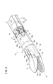
- FIG. 1 is a partially omitted perspective view of a medical manipulator according to an embodiment of the present invention. It is a partial cross section side view of the handle in the medical manipulator shown in FIG. It is a perspective view of the front-end
- FIG. 1 is a partially omitted perspective view of a medical manipulator 10 (hereinafter abbreviated as “manipulator 10”) according to the present embodiment.
- the manipulator 10 is a medical device for holding a needle, a thread, or a part of a living body with a gripper 12 (end effector) provided at the tip or touching the living body to perform a predetermined treatment.
- the manipulator 10 is configured as a needle driver capable of gripping a medical needle (curved needle or the like) with a gripper 12 provided at the tip.
- the manipulator 10 includes a distal end working unit 14 (operation unit) including a gripper 12, a handle 16 that drives the gripper 12, and a shaft 18 that couples the gripper 12 and the handle 16.
- the gripper 12 is a portion for performing a surgical procedure.
- the gripper 12 includes first and second gripper members 60 and 61 and is configured to open and close based on a predetermined opening and closing operation axis.
- the tip operating unit 14 including the gripper 12 can be changed in posture with a plurality of degrees of freedom with respect to the shaft 18.
- the distal end working unit 14 tilts to the left and right with respect to the axis of the shaft 18 (swinging operation), and a “roll” that rotates around the longitudinal axis of the distal end working unit 14.
- the tilting operation may be an operation of tilting up and down with respect to the axis of the shaft 18 instead of swinging in the left-right direction.
- the shaft 18 is a long and thin tubular member, and the hollow portion receives power necessary for opening / closing the gripper 12, roll operation and tilting operation of the distal end operation unit 14 from the handle 16 side.
- a plurality of members constituting a power transmission mechanism for transmitting to the distal end working unit 14 are inserted and arranged.
- the handle 16 includes a handle body 20 including a plurality of operation units, and a drive unit 22 that is detachable from the handle body 20 and includes a motor 38.
- the motor 38 is mounted on the handle body 20 while the drive unit 22 is mounted. When driven, the driving force of the motor 38 is configured to be transmitted to the distal end working unit 14. For this reason, the manipulator body including the handle body 20, the shaft 18 and the distal end working unit 14 is discarded after being used a predetermined number of times, while the drive unit 22 is used many times by changing the connected manipulator body. Can be used.
- the handle body 20 includes a body portion 23 to which the base end of the shaft 18 is connected, a lever 24 provided on the body portion 23 and constituting an opening / closing operation portion, and a tilting wheel provided on the body portion 23 and constituting a tilt operation portion. 26 (operation unit) and a roll switch 28 provided on the body unit 23 and constituting a roll operation unit.
- the body portion 23 is a portion that is gripped by the user when the manipulator 10 is used.
- the body portion 23 is configured in a stick shape extending slightly longer in the axial direction of the shaft 18.
- the body portion 23 includes a housing 29 including an upper cover 29 a and a lower cover 29 b, and driving components such as pulleys, gears, and wires are disposed in the housing 29.
- a lever 24 for opening and closing the gripper 12 is provided at the lower portion of the body portion 23 so as to be swingable up and down with the tip side as a fulcrum.
- the lever 24 is configured as a manual operation unit, and the operation force on the lever 24 is mechanically transmitted to the gripper 12 of the tip operation unit 14, so that the gripper 12 is opened and closed.
- the gripper 12 is opened with the lever 24 opened, and the gripper 12 is closed when the lever 24 is closed.
- the tilting wheel 26 for tilting the distal end working unit 14 is provided near the center in the longitudinal direction of the body 23.
- the tilting wheel 26 is configured as a manual operation unit, and the tilting wheel 26 is partially exposed from openings 27 provided on the left and right sides of the housing 29.
- the tilting wheel 26 is rotationally operated, the operating force is mechanically transmitted to the tip operating unit 14 via the tilting power transmission system provided in the handle 16 and the shaft 18, and the tip operating unit 14 is It tilts in a non-parallel direction (left-right direction or up-down direction) with respect to the axis of the shaft 18.
- the roll switch 28 for causing the tip operating unit 14 to roll is provided on the upper portion of the body 23 near the tip.
- the roll switch 28 is configured as an electric operation unit that gives an operation command to the motor 38 via the controller 44.
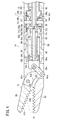
- FIG. 2 is a partial cross-sectional side view of the handle 16 in the manipulator 10.
- the drive unit 22 includes a housing 36, a motor 38 (drive source) disposed in the housing 36, and a drive gear 40 (pinion gear) fixed to the output shaft of the motor 38.
- the handle body 20 can be attached to and detached from the rear part.
- the drive unit 22 is connected to the controller 44 via a cable 42 including a power line and a signal line.
- the controller 44 performs power supply and drive control to the motor 38, and receives power from an external power source.
- a signal corresponding to the operation is transmitted to the controller 44, and the controller 44 controls driving of the motor 38.
- a handle-side connector 50 is provided at the rear part of the body part 23 of the handle main body 20, and a unit-side connector 52 is provided at the rear part of the drive unit 22.
- a signal corresponding to the state of the roll switch 28 is transmitted to the controller via the connector 54 and the signal line of the cable 42.
- the motor 38 mounted on the drive unit 22 is driven under the control action of the controller 44.
- the roll operation of the distal end working unit 14 is electrically driven by the motor 38, and the tilting operation and the opening / closing operation of the distal end working unit 14 are manual drive, but in a modified example of the manipulator 10
- one or both of the tilting operation and the opening / closing operation may be configured as an electric drive.
- FIG. 3 is a perspective view showing the distal end working unit 14 connected to the distal end of the shaft 18.
- FIG. 4 is a longitudinal sectional view of the distal end working unit 14.
- the distal end working unit 14 includes a gripper 12 that can be opened and closed, a hollow cylindrical rotating sleeve 56 to which the gripper 12 is fixed, and an inner peripheral portion of the rotating sleeve 56 around the axis. And a distal-end fulcrum block 58 that is rotatably supported.
- the gripper 12 includes a first gripper member 60 and a second gripper member 61.
- the first gripper member 60 and the second gripper member 61 are connected by a pin 63 so as to be rotatable about the gripper axis Og.
- the first gripper member 60 and the second gripper member 61 grip a gripping target such as a needle.
- the second gripper member 61 is connected to the transmission member 64 via the pin 65a, the link member 62, and the pin 65b.
- the transmission member 64 includes a guide tube portion 64a, a flange 64b provided at the distal end of the guide tube portion 64a, and a support arm 64c extending in parallel to each other in the distal direction from the edge of the flange 64b. 56 is arranged so as to be movable in the axial direction.
- a compression spring 66 is disposed between the transmission member 64 and the rotating sleeve 56.
- One end of the compression spring 66 abuts on the flange 64b of the transmission member 64, and the other end abuts on a stepped portion 56a provided on the inner peripheral portion of the rotary sleeve 56, so that the transmission member 64 is always attached elastically in the distal direction. Rush.
- the end collar 68 is inserted into the transmission member 64 from the front end side.
- the distal end portion of the end collar 68 is configured as an engagement bulging portion 68 a that contacts and engages the distal end surface of the guide tube portion 64 a of the transmission member 64.
- the end collar 68 is fixed to the distal end of the pull wire 70 that is passed through the joint portion 17 between the distal end working portion 14 and the shaft 18.
- the pull wire 70 is a member that moves forward and backward in the shaft 18 and the distal end working unit 14 in accordance with the operation of the handle 16 on the lever 24.
- the joint portion 17 between the distal end working portion 14 and the shaft 18 has a pair of joint pins 73 and 74 disposed on the tilt axis Oy.
- the pull wire 70 which is a part of the opening / closing drive transmission unit 80, can move forward and backward in a direction intersecting the axial direction of the joint pins 73 and 74 through a gap provided between the pair of joint pins 73 and 74.
- the transmission member 64 When the pull wire 70 is displaced in the proximal direction, the transmission member 64 is pressed in the proximal direction by the end collar 68 fixed to the pull wire 70, whereby the transmission member 64 is against the urging force of the compression spring 66. Displace in the end direction. As the transmission member 64 is displaced in the proximal direction, the second gripper member 61 connected to the link member 62 is rotated in a closing direction with respect to the first gripper member 60. In FIG. 4, the second gripper member 61 in a closed state up to a position where the gripping surface 61 b of the second gripper member 61 and the gripping surface 60 b of the first gripper member 60 come into contact with each other is indicated by a virtual line.
- the transmission member is generated by the elastic force of the compression spring 66. Since 64 advances, the 1st gripper member 60 rotates in the opening direction with respect to the 2nd gripper member 61 via the link member 62, and returns to the original state. This operation is the opening / closing operation of the gripper 12.
- the gripper 12 is configured such that the first gripper member 60 is configured as a fixed portion and the second gripper member 61 is configured as a movable portion, but both gripper members may be configured as movable portions. Good.
- the pull rod 91 is a tubular member, and is inserted into the shaft 18.
- the pull wire 70 and the pull rod 91 are connected within the shaft 18 so as to be relatively rotatable about the axis and to transmit a pulling force in the proximal direction of the pull rod 91 to the pull wire 70.
- the pull wire 70 connected to the pull rod 91 is also displaced in the axial direction, whereby the gripper 12 is opened and closed. Further, when the tip operating unit 14 performs a roll operation, the pull wire 70 can rotate with respect to the pull rod 91, so that the roll operation of the tip operating unit 14 is not hindered.
- the pull rod 91 is inserted into the hollow shaft 89, and its base end protrudes from the base end of the hollow shaft 89.
- the lever 24 is pivotally connected to the body portion 23 at a position near the front end of the body portion 23 at the front end portion thereof.
- the tip of a lever rod 96 disposed below the body 23 and substantially parallel to the longitudinal direction of the body 23 is rotatably connected.
- a hook holder 116 that supports the hook member 118 is fixed to the lower portion of the body portion 23, and a compression spring 98 is disposed between the distal end surface of the hook holder 116 and the distal end enlarged diameter portion 96 a of the lever rod 96.
- the This compression spring 98 always urges the lever rod 96 elastically in the distal direction. Therefore, the lever 24 connected to the lever rod 96 is always subjected to a force in the opening direction with respect to the body portion 23 by the elastic force of the compression spring 98.
- the driving force from the lever 24 is transmitted to the pull rod 91 and the pull wire 70 that constitute the opening / closing drive transmission unit via the intermediate transmission mechanism 100.
- a state where the lever 24 is opened with respect to the body part 23 is set as an initial position.
- the pull rod 91 has advanced to a position where the gripper 12 is fully opened.
- the lever rod 96 is displaced in the proximal direction.
- the gripper 12 operates in the closing direction.
- the distal end portion of the rotating sleeve 56 is fitted and fixed to the base portion 60 c of the first gripper member 60.
- a bevel gear portion 56 c is provided at the base end of the rotating sleeve 56.
- the gripper 12, the rotation sleeve 56, the transmission member 64, the end collar 68, and the compression spring 66 are integrally rotatable with respect to the distal end side fulcrum block 58 around the roll axis Or in the longitudinal direction of the distal end working unit 14. .
- the tip side fulcrum block 58 has a hollow cylindrical shape and is provided so that its posture can be changed with respect to the axial direction of the shaft 18 and rotatably supports the rotating sleeve 56 at its inner peripheral portion.
- the protrusion extending in the circumferential direction provided on the inner periphery of the distal end side fulcrum block 58 and the annular recess 56d provided in the rotational sleeve 56 are engaged with each other so that the rotational sleeve 56 is in contact with the distal end side fulcrum block 58. It is connected so that it can rotate and cannot move in the axial direction.
- the tip side fulcrum block 58 and the shaft side fulcrum block 59 are connected to each other by joint pins 73 and 74 so as to be rotatable around the tilt axis Oy.
- the articulation pin 73, the tongue pieces 58b, 58c provided at the upper and lower portions of the distal end side fulcrum block 58, and the tongue pieces 59b, 59c provided at the upper and lower portions of the base end of the shaft side fulcrum block 59, 74 is fitted.
- the shaft side fulcrum block 59 is fixed to the tip of a hollow shaft main body 19 (see FIG. 3) that constitutes the body portion of the shaft 18.
- the shaft 18 is configured by the shaft-side fulcrum block 59 and the shaft body 19.
- the tilt axis Oy is set in the vertical direction, but may be set in another direction that intersects the axis of the shaft body 19.
- a bevel gear 86 is rotatably supported by one joint pin 73.
- the tooth portion 86 a of the bevel gear 86 meshes with a bevel gear portion 56 c provided at the proximal end of the rotating sleeve 56 and a bevel gear portion 88 a provided at the tip of the gear member 88.
- the gear member 88 is a hollow cylindrical member, and the pull wire 70 is inserted into the hollow portion.
- the roll operation of the distal end working unit 14 is performed by transmitting the driving force of the motor 38 to the distal end working unit 14 via the roll drive transmission system.
- the roll drive transmission system shown in FIG. 2 includes a motor 38, a drive gear 40 fixed to the output shaft 38a of the motor 38, a driven gear 41 meshing with the drive gear 40, and a hollow shaft to which the driven gear 41 is fixed. 89.
- the roll drive transmission system further includes a gear member 88 fixed to the tip of the hollow shaft 89, a bevel gear 86 that meshes with the gear member 88, and a rotating sleeve 56 that meshes with the bevel gear 86, as shown in FIG. 4.
- a roll drive transmission tube 131 is configured by the gear member 88 and the hollow shaft 89. Further, the roll drive transmission tube 131, the bevel gear 86, and the rotation sleeve 56 constitute a rotation drive transmission unit that transmits a rotation driving force from the handle 16 side to the distal end working unit 14 side.
- the opening / closing drive transmission unit 80 (the pull wire 70 and the pull rod 91) can appropriately transmit the opening / closing driving force to the gripper 12 with a simple configuration because the portion (pull wire 70) corresponding to the joint portion 17 has flexibility. Therefore, it is possible to realize a roll operation with an unlimited rotation range while maintaining a structure capable of opening / closing and tilting the tip operating unit 14 without complicating the mechanism of the tip operating unit 14.
- a driven pulley 90 is rotatably supported by the other joint pin 74.
- the driven pulley 90 is fixed to the inner surface of the tongue piece 58 c of the distal end side fulcrum block 58. Therefore, when the drive pulley 130 rotates, the driven pulley 90 and the distal end side fulcrum block 58 rotate integrally with respect to the shaft side fulcrum block 59.
- a wire 132 for tilting operation is wound around the driven pulley 90. A part of the wire 132 is fixed to the driven pulley 90 and is disposed up to the handle 16 side through the shaft 18.
- the distal end side fulcrum block 58 fixed to the driven pulley 90 rotates integrally with the driven pulley 90.
- the distal end working unit 14 including the distal end side fulcrum block 58, the rotation sleeve 56 and the gripper 12 rotates about the tilt axis Oy with respect to the shaft 18.
- This operation is the tilting operation of the distal end working unit 14.
- the tilting operation of the distal end working unit 14 has movable ranges on the plus side (right side) and the minus side (left side), respectively, with the state where the distal end working unit 14 is straight with respect to the shaft 18 being a neutral position (reference position).
- a drive pulley 130 that rotates in conjunction with the rotation of the tilting wheel 26 is provided in the handle body 20.
- a wire 132 for tilting operation is wound around the drive pulley 130.
- An annular space extending along the axis of the shaft 18 is provided between the outer periphery of the shaft 18 and the outer periphery of the roll drive transmission tube 131, and the wire 132 is inserted into the annular space. Then, it is wound around a driven pulley 90 (see FIG. 4 and the like) on the tip end side of the shaft 18.
- the manipulator 10 further includes a brake mechanism 134 that restricts the movement of the power transmission mechanism between the tilting wheel 26 and the distal end working unit 14 and a brake release mechanism 136 that releases the braking by the brake mechanism 134.
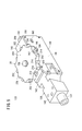
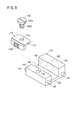
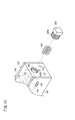
- FIG. 5 is a perspective view of the mechanism unit 133 provided in the handle body 20.
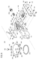
- FIG. 6 is an exploded perspective view of the mechanism unit 133.
- FIG. 7 is a partial cross-sectional plan view of the mechanism unit 133.
- FIG. 8 is a longitudinal sectional view of the mechanism unit 133.
- the mechanism unit 133 includes a frame 138, a tilting wheel 26 rotatably attached to the frame 138, a brake mechanism 134 incorporated in the frame 138, and a brake release mechanism 136 incorporated in the frame 138.
- the mechanism unit 133 is substantially entirely disposed inside the handle body 20 except for a part.
- the frame 138 includes a tip side component 140 having a through hole 139 penetrating in the front-rear direction, and a mechanism box 142 having an internal space 141 provided behind the tip side component 140 and communicating with the through hole 139.
- the shaft 18 is inserted and fixed on the distal end side.
- the frame 138 includes a front end side component 140, a frame main body 144 that constitutes the upper wall, the rear wall, and the lower wall of the mechanism box portion 142, a right side wall plate 146 that constitutes a right side wall of the mechanism box portion 142, and a mechanism box portion. 142 and a left side wall plate 148 constituting the left side wall.
- the right side wall plate 146 and the left side wall plate 148 are fixed to the frame main body 144 by appropriate fixing means (screws 150 in the illustrated example).
- a cylindrical projection 151 provided at the tip of the frame 138 protrudes from the tip of the housing 29.
- a bearing 154 is disposed above the frame 138 via a bearing housing 152.
- the bearing housing 152 is fixed to the frame 138 by appropriate means (screws 156 in the illustrated example), and the bearing 154 is mounted inside the bearing housing 152.
- the wheel shaft portion 158 fixed to the tilting wheel 26 with the screw 156 is supported by the bearing 154. With the above configuration, the tilting wheel 26 is rotatably supported with respect to the frame 138.
- the tilting wheel 26 is rotatable about the vertical axis of the manipulator 10.
- the drive pulley 130 is coaxially connected to the tilting wheel 26 via the wheel shaft portion 158, so that the tilting wheel 26 and the drive pulley 130 rotate integrally.
- the end of the wheel shaft 158 opposite to the side on which the tilting wheel 26 is fixed is supported by another bearing 160 provided on the frame 138.
- a drive pulley 130 around which the wire 132 is wound is provided below the portion of the wheel shaft portion 158 supported by the bearing 154.
- the drive pulley 130 is disposed between the bearing 154 and the bearing 160.
- the wire 132 includes a first intermediate pulley 162 and a second intermediate pulley 164 disposed in front of the driving pulley 130, a first tension pulley 166 disposed in the rear of the driving pulley 130, and a first pulley. It is wound around a two-tension pulley 168.
- the first intermediate pulley 162 and the second intermediate pulley 164 are rotatable in the frame 138 about the axis in the direction perpendicular to the rotation axis of the drive pulley 130 (the left-right direction of the manipulator 10) in front of the drive pulley 130. Supported by The first intermediate pulley 162 and the second intermediate pulley 164 are juxtaposed in a direction perpendicular to the rotation axis of the drive pulley 130 and are arranged at different heights.
- the first tension pulley 166 and the second tension pulley 168 are arranged at a distance from each other in the left-right direction (the direction perpendicular to the paper surface of FIG. 8), and the rotation axis of the drive pulley 130. It is supported so as to be rotatable about an axis in a parallel direction (vertical direction of the manipulator 10).
- the first tension pulley 166 is rotatably supported on the tip end portion of the pulley holder 171 by the pulley shaft 173.
- the second tension pulley 168 is also supported in the same manner as the first tension pulley 166.
- Two adjustment bolts 170 are provided corresponding to each of the first tension pulley 166 and the second tension pulley 168.
- the screw rod 170a of the adjustment bolt 170 is inserted from the rear through a through-hole 172 provided in the rear wall 138b of the frame 138, and the head 170b comes into contact with the rear wall 138b.
- the adjustment bolt 170 is rotated, the pulley holder 171 moves in the front-rear direction by a screwing action.
- one adjusting bolt 170 By operating one adjusting bolt 170, the position of the first tension pulley 166 supported by one pulley holder 171 is adjusted, and one side portion of the wire 132 between the driving pulley 130 and the driven pulley 90 is adjusted. The tension applied to can be adjusted. Further, by operating the other adjustment bolt 170, the position of the second tension pulley 168 supported by the other pulley holder 171 is adjusted, and the other side portion of the wire 132 between the drive pulley 130 and the driven pulley 90 is adjusted. The tension applied to can be adjusted.
- the brake mechanism 134 includes a brake rotor 174 that rotates in conjunction with the rotation of the tilting wheel 26, a brake shoe 176 that can contact the outer periphery of the brake rotor 174, a slide member 178 to which the brake shoe 176 is attached, And an elastic member 180 that elastically biases the member 178.
- the brake rotor 174 is provided on a power transmission path between the tilting wheel 26 and the distal end working unit 14, and more specifically, as shown in FIG. It is provided adjacent to the pulley 130.
- the brake rotor 174 has a disk shape, and a first gear 175A is provided on the outer peripheral portion along the circumferential direction.
- the brake shoe 176 can move forward and backward with respect to the brake rotor 174.
- a second gear 175B that can mesh with the first gear 175A is provided at a portion of the brake shoe 176 that faces the outer periphery of the brake rotor 174.
- the second gear 175 ⁇ / b> B extends in an arc shape that fits the outer peripheral portion of the brake rotor 174.
- the brake shoe 176 is an L-shaped component in the illustrated example, and is attached to the slide member 178 by a fixing means (bolt 182 in the illustrated example).
- the bolt 182 has a head 182a, a screw rod portion 182b formed with a male screw, and an intermediate portion 182c formed between the head 182a and the screw rod portion 182b.
- the screw rod portion 182b is screwed into the screw hole 179 provided in the slide member 178.
- the outer diameter of the intermediate part 182c is smaller than the outer diameter of the head part 182a and larger than the outer diameter of the screw rod part 182b.
- the intermediate portion 182c is disposed in a hole 177a provided in the mounting plate 177 of the brake shoe 176, and the mounting plate 177 is disposed between the head 182a of the bolt 182 and the slide member 178.
- the outer diameter of the intermediate portion 182c is slightly smaller than the inner diameter of the hole 177a provided in the mounting plate 177, and the axial thickness of the intermediate portion 182c is slightly larger than the thickness of the mounting plate 177. For this reason, a slight gap is provided between the outer peripheral surface of the intermediate portion 182c and the inner wall surface constituting the hole portion 177a, and between the upper surface of the mounting plate 177 and the lower surface of the head portion 182a. In this way, the brake shoe 176 is attached to the slide member 178 with some play. In other words, the brake shoe 176 is attached to the slide member 178 so as to be slightly swingable about the axis of the bolt 182 with respect to the slide member 178.
- the slide member 178 is always elastically pressed to the brake rotor 174 side by the elastic member 180 and can move forward and backward with respect to the brake rotor 174.
- the slide member 178 has a front part 184 that constitutes the front side, a rear part 186 that constitutes the rear side, and an intermediate component part 188 that connects the lower parts of the front part 184 and the rear part 186,
- a groove 190 extending in the width direction of the slide member 178 is formed by the rear surface of the front portion 184, the front surface of the rear portion 186, and the upper surface of the intermediate component portion 188.
- An insertion hole 192 that opens rearward is formed at the center in the width direction of the rear portion. One end side of the elastic member 180 is inserted into the insertion hole 192.
- pins 194 protrude from the left and right side surfaces of the slide member 178 at positions spaced apart from each other. These pins 194 are slidably inserted in the front-rear direction into elongated holes 196 formed in the right side wall plate 146 and the left side wall plate 148 of the frame 138 and extending in the front-rear direction. With this configuration, the slide member 178 can move forward and backward with respect to the brake rotor 174 integrally with the brake shoe 176 in the frame 138.
- the elastic member 180 is configured by a coil spring in this embodiment. Instead of the coil spring, other forms of springs (plate springs, torsion springs, etc.) or rubber bodies may be used.
- An insertion hole 198 of a size that allows the elastic member 180 to be inserted is provided in a rear wall 138 b that constitutes the opposite side of the brake rotor 174 with respect to the slide member 178 in the frame 138.
- a presser member 200 that holds the elastic member 180 is attached to the insertion hole 198.
- the elastic member 180 is inserted into the frame 138 through the insertion hole 198 from the rear side of the frame 138 in which the slide member 178 is disposed inside, and then the presser is pressed. By attaching the member 200 to the insertion hole 198, the elastic member 180 can be disposed in a compressed state between the pressing member 200 and the slide member 178.
- the holding member 200 is attached to the insertion hole 198 so that the compression amount of the elastic member 180 can be changed.
- a female screw part 198 a is formed on the inner peripheral part forming the insertion hole 198
- a male screw part 200 a is formed on the outer peripheral part of the pressing member 200.
- the amount of compression of the elastic member 180 changes according to the degree of screwing of the pressing member 200, whereby the pressing force of the brake shoe 176 against the brake rotor 174 can be adjusted.
- the operation of the brake mechanism 134 configured as described above will be described.
- braking force is generated by the brake shoe 176 being pressed against the brake rotor 174 based on the elastic force of the elastic member 180.
- the rotation of the brake rotor 174 is blocked, and the movement of the power transmission mechanism related to the tilting operation between the tilting wheel 26 and the tip operating unit 14 is blocked.
- the angle of the gripper 12 with respect to the shaft 18 is prevented from being changed by the reaction force from the living tissue. .
- a slide member 178 that is elastically pressed toward the brake rotor 174 side by the elastic member 180 and can move forward and backward with respect to the brake rotor 174 is provided.
- the brake shoe 176 is fixed to the slide member 178. Parts. As described above, the brake shoe 176 is not integrally molded with the component pressed against the elastic member 180 but is a component attached to the slide member 178 configured as a separate component. In this case, it is only necessary to change the brake shoe 176 without changing the slide member 178, so that it is possible to flexibly cope with a design change.
- the second gear 175B extends in an arc shape that fits the outer peripheral portion of the brake rotor 174, and the brake shoe 176 slides in a state in which it can swing slightly with respect to the slide member 178. Attached to member 178.
- the brake shoe 176 automatically changes the angle so that the first gear 175A and the second gear 175B mesh over a predetermined range in the circumferential direction. . Therefore, the brake shoe 176 is automatically aligned with respect to the brake rotor 174, and the braking force can be suitably exerted.
- the rear wall 138 b of the frame 138 is provided with an insertion hole 198 that is large enough to allow the elastic member 180 to be inserted therein, and the pressing member 200 is attached to the insertion hole 198.
- the brake release mechanism 136 includes a release button 202 (release operation unit) provided on the tilting wheel 26 and an inner side of the release button 202 disposed inside the tilting wheel 26. And a lever mechanism 204 that is pressed in accordance with the movement. When the lever mechanism 204 is operated in accordance with the inward pressing operation on the release button 202, the braking by the brake mechanism 134 is released.
- a plurality of release buttons 202 are provided on the outer peripheral portion of the tilting wheel 26 so as to protrude radially outward from the outer peripheral portion with an interval in the circumferential direction.
- nine release buttons 202 are arranged at equal intervals on the outer peripheral portion of the tilting wheel 26.
- the tilting wheel 26 has a disk part 206 with the wheel shaft part 158 fixed at the center, and a peripheral part 208 provided on the outer edge of the disk part 206 and projecting downward from the disk part 206. As shown in FIG. 8, an annular recess 210 is formed inside the peripheral edge 208. Further, as shown in FIG. 6, a plurality of (9 in the illustrated example) button holes 212 are provided in the peripheral edge portion 208 so as to penetrate in the radial direction of the tilting wheel 26 at intervals in the circumferential direction. In each of the button holes 212, the release button 202 is disposed so as to be movable in the radial direction. In the assembly process, the release button 202 is inserted from the inside of the peripheral edge 208.
- a plurality of convex portions 214 and concave portions 216 are alternately formed in the peripheral portion 208 along the circumferential direction, and a plurality of release buttons 202 are provided in the plurality of concave portions 216, respectively.
- the recess 216 in the illustrated example has an arc shape.
- a locking piece 203 protruding in substantially opposite directions is provided on one end side of the release button 202.
- the locking piece 203 functions as a retaining portion that prevents the release button 202 from slipping outward from the tilting wheel 26.
- a backup member 218 that pushes the release button 202 outward is provided inside the peripheral edge 208.
- the backup member 218 is a leaf spring that is curved in a ring shape so as to have an outer diameter larger than the inner diameter of the peripheral edge 208 in a natural state, and is disposed in the annular recess 210 of the peripheral edge 208. Then, both ends overlap to form a single ring.
- the release button 202 is pushed outward in the radial direction of the tilting wheel 26 by the backup member 218 arranged inside them. This prevents the release button 202 from falling inward from the button hole 212 formed in the peripheral edge 208 of the tilting wheel 26.
- a pair of lever mechanisms 204 are provided.
- first lever mechanism 204A one lever mechanism 204
- second lever mechanism 204B the other lever mechanism 204
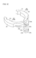
- each lever mechanism 204 includes a lever 220 that is pressed and rotated inside the tilting wheel 26 as the release button 202 moves inward, and a shaft portion provided on the lever 220. 222a and 222b, and cams 224a and 224b that operate with the shaft portions 222a and 222b as fulcrums.
- the lever 220 has a curved shape along the peripheral edge 208 of the tilting wheel 26, and an arc-shaped pressed portion 221 is provided on the outer peripheral side thereof.
- the radius of curvature of the pressed portion 221 is substantially the same as or slightly smaller than the inner diameter of the backup member 218 disposed inside the peripheral portion 208.
- the lever 220 can receive a pressure from the release button 202 located outside the angle range where the pressed part 221 is formed.
- the two levers 220 have the same shape and are arranged symmetrically.
- a base portion 220a is formed on the side opposite to the side where the pressed portion 221 is formed, and the shaft portions 222a and 222b are coupled so as to protrude downward from the base portion 220a. ing.
- the two shaft portions 222a and 222b are rotatably supported by two shaft holes 225 formed in the upper wall of the frame 138, respectively.
- the shaft portions 222a and 222b coupled to the two levers 220 have different lengths.
- the shaft portion 222a of the first lever mechanism 204A is longer than the shaft portion 222b of the second lever mechanism 204B.
- the cams 224a and 224b are provided at the lower ends of the shaft portions 222a and 222b, respectively. As shown in FIG. 8, the cams 224 a and 224 b are disposed in the frame 138.
- the cam 224a provided in the first lever mechanism 204A is referred to as a “first cam 224a”
- the cam 224b provided in the second lever mechanism 204B Is referred to as "second cam 224b”.
- the first cam 224a is disposed below the second cam 224b, and the two cams 224a and 224b are provided at positions overlapping each other in plan view so as not to interfere with each other.
- the second cam 224b has a shape in which a part thereof is recessed so as not to interfere with the shaft portion 222a of the first lever mechanism 204A during operation within the movable range.
- the two cams 224 a and 224 b are arranged in a groove 190 provided in the slide member 178 in a state where the cams 224 a and 224 b are in contact with the center in the width direction of the front surface of the rear portion 186 of the slide member 178.
- the slide member 178 elastically biased toward the brake rotor 174 by the elastic member 180 presses the two cams 224a and 224b.
- the pressing force received by the cams 224a and 224b acts in a direction to open the two lever mechanisms 204.
- the first lever mechanism 204A operates based on an operation on a part of the release buttons 202 (in the state shown in FIG. 7, the release buttons 202a and 202b) of the plurality of release buttons 202, and the second lever mechanism 204B includes a plurality of release buttons 202B.
- the release button 202 is activated based on an operation on another part of the release buttons 202 (release buttons 202c and 202d in the state shown in FIG. 7). Accordingly, braking by the brake mechanism 134 is released when one of the pair of lever mechanisms 204 is operated.
- the release button 202 provided on the tilting wheel 26 is pressed inward.
- a portion of the tilting wheel 26 exposed to the opening 27 provided in the housing 29 of the handle body 20 is touched, but a plurality of release buttons 202 are provided in the circumferential direction of the outer peripheral portion of the tilting wheel 26. Is provided, the operator can reliably press the release button 202.
- the release button 202 is pressed, at least one of the two lever mechanisms 204 (specifically, the lever 220) is pressed through the backup member 218 disposed inside the tilting wheel 26.
- the cams 224a and 224b resist the elastic force of the elastic member 180 in the direction opposite to the brake rotor 174 (in the illustrated example).
- the slide member 178 is pressed and displaced rearward of the manipulator 10.
- the brake shoe 176 attached to the slide member 178 is also displaced together with the slide member 178.
- the two cams 224 a and 224 b are both in contact with the center in the width direction of the slide member 178. Accordingly, even when only one of the two lever mechanisms 204 is rotated, one of the cams 224a and 224b presses the center in the width direction of the slide member 178, so that the slide member 178 can be smoothly displaced. .
- the brake shoe 176 With the displacement of the slide member 178, the brake shoe 176 is separated from the brake rotor 174, and the brake rotor 174 becomes rotatable. That is, the brake by the brake mechanism 134 is released. Accordingly, by applying an operation force in the rotation direction to the tilting wheel 26 with the release button 202 pressed, the tilting wheel 26 can be rotated and the gripper 12 can be tilted. In this case, since the release button 202 rotates integrally with the tilting wheel 26, the rotation operation of the tilting wheel 26 can be easily performed while maintaining the state where the release button 202 is pressed inward.
- the release button 202 for releasing the brake is provided on the tilt wheel 26 for tilting the gripper 12, so that the operator of the manipulator 10 can tilt the wheel. 26, the release button 202 can be easily touched with a hand. Thereby, braking by the brake mechanism 134 can be easily and quickly released with one hand. That is, the brake release operation and the tilting wheel 26 rotation operation can be easily and reliably performed with one hand.
- the brake release mechanism 136 can be configured compactly, and the manipulator 10 in which the brake mechanism 134 is incorporated is small and lightweight. Can contribute to
- the lever mechanism 204 includes a lever 220 that is pressed and rotated inside the tilting wheel 26 as the release button 202 moves inward, and a shaft portion 222 a provided on the lever 220. 222b and cams 224a and 224b that operate with the shaft portions 222a and 222b as fulcrums, and the cams 224a and 224b operate to separate the brake shoe 176 from the brake rotor 174 in accordance with the operation on the release button 202. As a result, braking is released. Since it is configured in this manner, the brake can be released with a low operating force by appropriately setting the lever ratio of the lever mechanism 204.
- two lever mechanisms 204 are provided, and braking is released by operating one of the lever mechanisms 204, so that the brake release operation can be performed more easily and reliably.
- the release button 202 is provided on the outer peripheral portion of the tilting wheel 26 so as to be displaceable in the inner and outer directions. According to this configuration, since the brake can be released by pressing the release button 202 inward, and the rotation operation of the tilting wheel 26 can be performed in that state, the brake release operation and the subsequent rotation operation can be swallowed. Can be done smoothly.
- the release button 202 at a position not corresponding to the lever 220 falls off the tilting wheel 26. There is nothing.
- a plurality of release buttons 202 are provided on the outer peripheral portion of the tilting wheel 26 at different positions in the circumferential direction. According to this configuration, since not only one release button 202 but also a plurality of release buttons 202 are provided, the brake release operation can be performed simply by selecting and pressing the release button 202 that is easy to be held by the user.
- a plurality of convex portions 214 and concave portions 216 are alternately formed along the circumferential direction on the outer peripheral portion of the tilting wheel 26, and a plurality of release buttons 202 are provided in the plurality of concave portions 216, respectively. According to this configuration, since the release button 202 is not easily pressed by simply touching the tilting wheel 26, unintended brake release can be effectively suppressed.
Landscapes
- Engineering & Computer Science (AREA)
- General Engineering & Computer Science (AREA)
- Health & Medical Sciences (AREA)
- Mechanical Engineering (AREA)
- Surgery (AREA)
- Life Sciences & Earth Sciences (AREA)
- Biomedical Technology (AREA)
- Nuclear Medicine, Radiotherapy & Molecular Imaging (AREA)
- Ophthalmology & Optometry (AREA)
- Heart & Thoracic Surgery (AREA)
- Medical Informatics (AREA)
- Molecular Biology (AREA)
- Animal Behavior & Ethology (AREA)
- General Health & Medical Sciences (AREA)
- Public Health (AREA)
- Veterinary Medicine (AREA)
- Manipulator (AREA)
- Surgical Instruments (AREA)
Priority Applications (2)
| Application Number | Priority Date | Filing Date | Title |
|---|---|---|---|
| EP13841694.6A EP2901948B1 (en) | 2012-09-26 | 2013-09-24 | Brake release mechanism and medical manipulator provided with same |
| US14/669,808 US10064639B2 (en) | 2012-09-26 | 2015-03-26 | Brake release mechanism and medical manipulator provided with same |
Applications Claiming Priority (2)
| Application Number | Priority Date | Filing Date | Title |
|---|---|---|---|
| JP2012212060A JP6082553B2 (ja) | 2012-09-26 | 2012-09-26 | ブレーキ解除機構及びこれを備えた医療用マニピュレータ |
| JP2012-212060 | 2012-09-26 |
Related Child Applications (1)
| Application Number | Title | Priority Date | Filing Date |
|---|---|---|---|
| US14/669,808 Continuation US10064639B2 (en) | 2012-09-26 | 2015-03-26 | Brake release mechanism and medical manipulator provided with same |
Publications (1)
| Publication Number | Publication Date |
|---|---|
| WO2014050783A1 true WO2014050783A1 (ja) | 2014-04-03 |
Family
ID=50388184
Family Applications (1)
| Application Number | Title | Priority Date | Filing Date |
|---|---|---|---|
| PCT/JP2013/075631 Ceased WO2014050783A1 (ja) | 2012-09-26 | 2013-09-24 | ブレーキ解除機構及びこれを備えた医療用マニピュレータ |
Country Status (4)
| Country | Link |
|---|---|
| US (1) | US10064639B2 (enExample) |
| EP (1) | EP2901948B1 (enExample) |
| JP (1) | JP6082553B2 (enExample) |
| WO (1) | WO2014050783A1 (enExample) |
Cited By (2)
| Publication number | Priority date | Publication date | Assignee | Title |
|---|---|---|---|---|
| WO2016168533A1 (en) * | 2015-04-16 | 2016-10-20 | Ethicon Endo-Surgery, Llc | Ultrasonic surgical instrument with articulation joint having plurality of locking positions |
| CN113081153A (zh) * | 2021-03-24 | 2021-07-09 | 李程 | 骨骼打磨成型器 |
Families Citing this family (423)
| Publication number | Priority date | Publication date | Assignee | Title |
|---|---|---|---|---|
| US20070084897A1 (en) | 2003-05-20 | 2007-04-19 | Shelton Frederick E Iv | Articulating surgical stapling instrument incorporating a two-piece e-beam firing mechanism |
| US9060770B2 (en) | 2003-05-20 | 2015-06-23 | Ethicon Endo-Surgery, Inc. | Robotically-driven surgical instrument with E-beam driver |
| US9072535B2 (en) | 2011-05-27 | 2015-07-07 | Ethicon Endo-Surgery, Inc. | Surgical stapling instruments with rotatable staple deployment arrangements |
| US8215531B2 (en) | 2004-07-28 | 2012-07-10 | Ethicon Endo-Surgery, Inc. | Surgical stapling instrument having a medical substance dispenser |
| US11998198B2 (en) | 2004-07-28 | 2024-06-04 | Cilag Gmbh International | Surgical stapling instrument incorporating a two-piece E-beam firing mechanism |
| US11890012B2 (en) | 2004-07-28 | 2024-02-06 | Cilag Gmbh International | Staple cartridge comprising cartridge body and attached support |
| US7934630B2 (en) | 2005-08-31 | 2011-05-03 | Ethicon Endo-Surgery, Inc. | Staple cartridges for forming staples having differing formed staple heights |
| US9237891B2 (en) | 2005-08-31 | 2016-01-19 | Ethicon Endo-Surgery, Inc. | Robotically-controlled surgical stapling devices that produce formed staples having different lengths |
| US10159482B2 (en) | 2005-08-31 | 2018-12-25 | Ethicon Llc | Fastener cartridge assembly comprising a fixed anvil and different staple heights |
| US11246590B2 (en) | 2005-08-31 | 2022-02-15 | Cilag Gmbh International | Staple cartridge including staple drivers having different unfired heights |
| US7669746B2 (en) | 2005-08-31 | 2010-03-02 | Ethicon Endo-Surgery, Inc. | Staple cartridges for forming staples having differing formed staple heights |
| US11484312B2 (en) | 2005-08-31 | 2022-11-01 | Cilag Gmbh International | Staple cartridge comprising a staple driver arrangement |
| US20070106317A1 (en) | 2005-11-09 | 2007-05-10 | Shelton Frederick E Iv | Hydraulically and electrically actuated articulation joints for surgical instruments |
| US8820603B2 (en) | 2006-01-31 | 2014-09-02 | Ethicon Endo-Surgery, Inc. | Accessing data stored in a memory of a surgical instrument |
| US11278279B2 (en) | 2006-01-31 | 2022-03-22 | Cilag Gmbh International | Surgical instrument assembly |
| US8708213B2 (en) | 2006-01-31 | 2014-04-29 | Ethicon Endo-Surgery, Inc. | Surgical instrument having a feedback system |
| US20120292367A1 (en) | 2006-01-31 | 2012-11-22 | Ethicon Endo-Surgery, Inc. | Robotically-controlled end effector |
| US8186555B2 (en) | 2006-01-31 | 2012-05-29 | Ethicon Endo-Surgery, Inc. | Motor-driven surgical cutting and fastening instrument with mechanical closure system |
| US11224427B2 (en) | 2006-01-31 | 2022-01-18 | Cilag Gmbh International | Surgical stapling system including a console and retraction assembly |
| US11793518B2 (en) | 2006-01-31 | 2023-10-24 | Cilag Gmbh International | Powered surgical instruments with firing system lockout arrangements |
| US7845537B2 (en) | 2006-01-31 | 2010-12-07 | Ethicon Endo-Surgery, Inc. | Surgical instrument having recording capabilities |
| US7753904B2 (en) | 2006-01-31 | 2010-07-13 | Ethicon Endo-Surgery, Inc. | Endoscopic surgical instrument with a handle that can articulate with respect to the shaft |
| US20110024477A1 (en) | 2009-02-06 | 2011-02-03 | Hall Steven G | Driven Surgical Stapler Improvements |
| US20110290856A1 (en) | 2006-01-31 | 2011-12-01 | Ethicon Endo-Surgery, Inc. | Robotically-controlled surgical instrument with force-feedback capabilities |
| US8992422B2 (en) | 2006-03-23 | 2015-03-31 | Ethicon Endo-Surgery, Inc. | Robotically-controlled endoscopic accessory channel |
| US8322455B2 (en) | 2006-06-27 | 2012-12-04 | Ethicon Endo-Surgery, Inc. | Manually driven surgical cutting and fastening instrument |
| US7506791B2 (en) | 2006-09-29 | 2009-03-24 | Ethicon Endo-Surgery, Inc. | Surgical stapling instrument with mechanical mechanism for limiting maximum tissue compression |
| US10568652B2 (en) | 2006-09-29 | 2020-02-25 | Ethicon Llc | Surgical staples having attached drivers of different heights and stapling instruments for deploying the same |
| US11980366B2 (en) | 2006-10-03 | 2024-05-14 | Cilag Gmbh International | Surgical instrument |
| US11291441B2 (en) | 2007-01-10 | 2022-04-05 | Cilag Gmbh International | Surgical instrument with wireless communication between control unit and remote sensor |
| US8652120B2 (en) | 2007-01-10 | 2014-02-18 | Ethicon Endo-Surgery, Inc. | Surgical instrument with wireless communication between control unit and sensor transponders |
| US8632535B2 (en) | 2007-01-10 | 2014-01-21 | Ethicon Endo-Surgery, Inc. | Interlock and surgical instrument including same |
| US8684253B2 (en) | 2007-01-10 | 2014-04-01 | Ethicon Endo-Surgery, Inc. | Surgical instrument with wireless communication between a control unit of a robotic system and remote sensor |
| US8827133B2 (en) | 2007-01-11 | 2014-09-09 | Ethicon Endo-Surgery, Inc. | Surgical stapling device having supports for a flexible drive mechanism |
| US11039836B2 (en) | 2007-01-11 | 2021-06-22 | Cilag Gmbh International | Staple cartridge for use with a surgical stapling instrument |
| US7669747B2 (en) | 2007-03-15 | 2010-03-02 | Ethicon Endo-Surgery, Inc. | Washer for use with a surgical stapling instrument |
| US8893946B2 (en) | 2007-03-28 | 2014-11-25 | Ethicon Endo-Surgery, Inc. | Laparoscopic tissue thickness and clamp load measuring devices |
| US11672531B2 (en) | 2007-06-04 | 2023-06-13 | Cilag Gmbh International | Rotary drive systems for surgical instruments |
| US8931682B2 (en) | 2007-06-04 | 2015-01-13 | Ethicon Endo-Surgery, Inc. | Robotically-controlled shaft based rotary drive systems for surgical instruments |
| US7753245B2 (en) | 2007-06-22 | 2010-07-13 | Ethicon Endo-Surgery, Inc. | Surgical stapling instruments |
| US11849941B2 (en) | 2007-06-29 | 2023-12-26 | Cilag Gmbh International | Staple cartridge having staple cavities extending at a transverse angle relative to a longitudinal cartridge axis |
| JP5410110B2 (ja) | 2008-02-14 | 2014-02-05 | エシコン・エンド−サージェリィ・インコーポレイテッド | Rf電極を有する外科用切断・固定器具 |
| US8636736B2 (en) | 2008-02-14 | 2014-01-28 | Ethicon Endo-Surgery, Inc. | Motorized surgical cutting and fastening instrument |
| US8573465B2 (en) | 2008-02-14 | 2013-11-05 | Ethicon Endo-Surgery, Inc. | Robotically-controlled surgical end effector system with rotary actuated closure systems |
| US8758391B2 (en) | 2008-02-14 | 2014-06-24 | Ethicon Endo-Surgery, Inc. | Interchangeable tools for surgical instruments |
| US9179912B2 (en) | 2008-02-14 | 2015-11-10 | Ethicon Endo-Surgery, Inc. | Robotically-controlled motorized surgical cutting and fastening instrument |
| US7866527B2 (en) | 2008-02-14 | 2011-01-11 | Ethicon Endo-Surgery, Inc. | Surgical stapling apparatus with interlockable firing system |
| US7819298B2 (en) | 2008-02-14 | 2010-10-26 | Ethicon Endo-Surgery, Inc. | Surgical stapling apparatus with control features operable with one hand |
| US11986183B2 (en) | 2008-02-14 | 2024-05-21 | Cilag Gmbh International | Surgical cutting and fastening instrument comprising a plurality of sensors to measure an electrical parameter |
| US9585657B2 (en) | 2008-02-15 | 2017-03-07 | Ethicon Endo-Surgery, Llc | Actuator for releasing a layer of material from a surgical end effector |
| US11272927B2 (en) | 2008-02-15 | 2022-03-15 | Cilag Gmbh International | Layer arrangements for surgical staple cartridges |
| US8210411B2 (en) | 2008-09-23 | 2012-07-03 | Ethicon Endo-Surgery, Inc. | Motor-driven surgical cutting instrument |
| US11648005B2 (en) | 2008-09-23 | 2023-05-16 | Cilag Gmbh International | Robotically-controlled motorized surgical instrument with an end effector |
| US9005230B2 (en) | 2008-09-23 | 2015-04-14 | Ethicon Endo-Surgery, Inc. | Motorized surgical instrument |
| US9386983B2 (en) | 2008-09-23 | 2016-07-12 | Ethicon Endo-Surgery, Llc | Robotically-controlled motorized surgical instrument |
| US8608045B2 (en) | 2008-10-10 | 2013-12-17 | Ethicon Endo-Sugery, Inc. | Powered surgical cutting and stapling apparatus with manually retractable firing system |
| US8517239B2 (en) | 2009-02-05 | 2013-08-27 | Ethicon Endo-Surgery, Inc. | Surgical stapling instrument comprising a magnetic element driver |
| US8444036B2 (en) | 2009-02-06 | 2013-05-21 | Ethicon Endo-Surgery, Inc. | Motor driven surgical fastener device with mechanisms for adjusting a tissue gap within the end effector |
| CA2751664A1 (en) | 2009-02-06 | 2010-08-12 | Ethicon Endo-Surgery, Inc. | Driven surgical stapler improvements |
| US8851354B2 (en) | 2009-12-24 | 2014-10-07 | Ethicon Endo-Surgery, Inc. | Surgical cutting instrument that analyzes tissue thickness |
| US8220688B2 (en) | 2009-12-24 | 2012-07-17 | Ethicon Endo-Surgery, Inc. | Motor-driven surgical cutting instrument with electric actuator directional control assembly |
| US8783543B2 (en) | 2010-07-30 | 2014-07-22 | Ethicon Endo-Surgery, Inc. | Tissue acquisition arrangements and methods for surgical stapling devices |
| US9629814B2 (en) | 2010-09-30 | 2017-04-25 | Ethicon Endo-Surgery, Llc | Tissue thickness compensator configured to redistribute compressive forces |
| US11812965B2 (en) | 2010-09-30 | 2023-11-14 | Cilag Gmbh International | Layer of material for a surgical end effector |
| US9232941B2 (en) | 2010-09-30 | 2016-01-12 | Ethicon Endo-Surgery, Inc. | Tissue thickness compensator comprising a reservoir |
| US11849952B2 (en) | 2010-09-30 | 2023-12-26 | Cilag Gmbh International | Staple cartridge comprising staples positioned within a compressible portion thereof |
| US8740038B2 (en) | 2010-09-30 | 2014-06-03 | Ethicon Endo-Surgery, Inc. | Staple cartridge comprising a releasable portion |
| US11298125B2 (en) | 2010-09-30 | 2022-04-12 | Cilag Gmbh International | Tissue stapler having a thickness compensator |
| US10945731B2 (en) | 2010-09-30 | 2021-03-16 | Ethicon Llc | Tissue thickness compensator comprising controlled release and expansion |
| US9351730B2 (en) | 2011-04-29 | 2016-05-31 | Ethicon Endo-Surgery, Llc | Tissue thickness compensator comprising channels |
| US10405854B2 (en) | 2010-09-30 | 2019-09-10 | Ethicon Llc | Surgical stapling cartridge with layer retention features |
| US9364233B2 (en) | 2010-09-30 | 2016-06-14 | Ethicon Endo-Surgery, Llc | Tissue thickness compensators for circular surgical staplers |
| US12213666B2 (en) | 2010-09-30 | 2025-02-04 | Cilag Gmbh International | Tissue thickness compensator comprising layers |
| US9320523B2 (en) | 2012-03-28 | 2016-04-26 | Ethicon Endo-Surgery, Llc | Tissue thickness compensator comprising tissue ingrowth features |
| US8695866B2 (en) | 2010-10-01 | 2014-04-15 | Ethicon Endo-Surgery, Inc. | Surgical instrument having a power control circuit |
| JP6026509B2 (ja) | 2011-04-29 | 2016-11-16 | エシコン・エンド−サージェリィ・インコーポレイテッドEthicon Endo−Surgery,Inc. | ステープルカートリッジ自体の圧縮可能部分内に配置されたステープルを含むステープルカートリッジ |
| US11207064B2 (en) | 2011-05-27 | 2021-12-28 | Cilag Gmbh International | Automated end effector component reloading system for use with a robotic system |
| US9044230B2 (en) | 2012-02-13 | 2015-06-02 | Ethicon Endo-Surgery, Inc. | Surgical cutting and fastening instrument with apparatus for determining cartridge and firing motion status |
| BR112014024194B1 (pt) | 2012-03-28 | 2022-03-03 | Ethicon Endo-Surgery, Inc | Conjunto de cartucho de grampos para um grampeador cirúrgico |
| BR112014024102B1 (pt) | 2012-03-28 | 2022-03-03 | Ethicon Endo-Surgery, Inc | Conjunto de cartucho de prendedores para um instrumento cirúrgico, e conjunto de atuador de extremidade para um instrumento cirúrgico |
| CN104334098B (zh) | 2012-03-28 | 2017-03-22 | 伊西康内外科公司 | 包括限定低压强环境的胶囊剂的组织厚度补偿件 |
| US9101358B2 (en) | 2012-06-15 | 2015-08-11 | Ethicon Endo-Surgery, Inc. | Articulatable surgical instrument comprising a firing drive |
| BR112014032776B1 (pt) | 2012-06-28 | 2021-09-08 | Ethicon Endo-Surgery, Inc | Sistema de instrumento cirúrgico e kit cirúrgico para uso com um sistema de instrumento cirúrgico |
| US20140001234A1 (en) | 2012-06-28 | 2014-01-02 | Ethicon Endo-Surgery, Inc. | Coupling arrangements for attaching surgical end effectors to drive systems therefor |
| US20140005718A1 (en) | 2012-06-28 | 2014-01-02 | Ethicon Endo-Surgery, Inc. | Multi-functional powered surgical device with external dissection features |
| US12383267B2 (en) | 2012-06-28 | 2025-08-12 | Cilag Gmbh International | Robotically powered surgical device with manually-actuatable reversing system |
| US9649111B2 (en) | 2012-06-28 | 2017-05-16 | Ethicon Endo-Surgery, Llc | Replaceable clip cartridge for a clip applier |
| CN104487005B (zh) | 2012-06-28 | 2017-09-08 | 伊西康内外科公司 | 空夹仓闭锁件 |
| US11202631B2 (en) | 2012-06-28 | 2021-12-21 | Cilag Gmbh International | Stapling assembly comprising a firing lockout |
| US9289256B2 (en) | 2012-06-28 | 2016-03-22 | Ethicon Endo-Surgery, Llc | Surgical end effectors having angled tissue-contacting surfaces |
| US20140001231A1 (en) | 2012-06-28 | 2014-01-02 | Ethicon Endo-Surgery, Inc. | Firing system lockout arrangements for surgical instruments |
| MX364729B (es) | 2013-03-01 | 2019-05-06 | Ethicon Endo Surgery Inc | Instrumento quirúrgico con una parada suave. |
| MX368026B (es) | 2013-03-01 | 2019-09-12 | Ethicon Endo Surgery Inc | Instrumento quirúrgico articulable con vías conductoras para la comunicación de la señal. |
| US9351727B2 (en) | 2013-03-14 | 2016-05-31 | Ethicon Endo-Surgery, Llc | Drive train control arrangements for modular surgical instruments |
| US9629629B2 (en) | 2013-03-14 | 2017-04-25 | Ethicon Endo-Surgey, LLC | Control systems for surgical instruments |
| US10405857B2 (en) | 2013-04-16 | 2019-09-10 | Ethicon Llc | Powered linear surgical stapler |
| BR112015026109B1 (pt) | 2013-04-16 | 2022-02-22 | Ethicon Endo-Surgery, Inc | Instrumento cirúrgico |
| MX369362B (es) | 2013-08-23 | 2019-11-06 | Ethicon Endo Surgery Llc | Dispositivos de retraccion de miembros de disparo para instrumentos quirurgicos electricos. |
| US10624634B2 (en) | 2013-08-23 | 2020-04-21 | Ethicon Llc | Firing trigger lockout arrangements for surgical instruments |
| US9962161B2 (en) | 2014-02-12 | 2018-05-08 | Ethicon Llc | Deliverable surgical instrument |
| BR112016019387B1 (pt) | 2014-02-24 | 2022-11-29 | Ethicon Endo-Surgery, Llc | Sistema de instrumento cirúrgico e cartucho de prendedores para uso com um instrumento cirúrgico de fixação |
| US9820738B2 (en) | 2014-03-26 | 2017-11-21 | Ethicon Llc | Surgical instrument comprising interactive systems |
| US12232723B2 (en) | 2014-03-26 | 2025-02-25 | Cilag Gmbh International | Systems and methods for controlling a segmented circuit |
| US20150272582A1 (en) | 2014-03-26 | 2015-10-01 | Ethicon Endo-Surgery, Inc. | Power management control systems for surgical instruments |
| US9826977B2 (en) | 2014-03-26 | 2017-11-28 | Ethicon Llc | Sterilization verification circuit |
| BR112016021943B1 (pt) | 2014-03-26 | 2022-06-14 | Ethicon Endo-Surgery, Llc | Instrumento cirúrgico para uso por um operador em um procedimento cirúrgico |
| US20150297222A1 (en) | 2014-04-16 | 2015-10-22 | Ethicon Endo-Surgery, Inc. | Fastener cartridges including extensions having different configurations |
| CN106456158B (zh) | 2014-04-16 | 2019-02-05 | 伊西康内外科有限责任公司 | 包括非一致紧固件的紧固件仓 |
| CN106456159B (zh) | 2014-04-16 | 2019-03-08 | 伊西康内外科有限责任公司 | 紧固件仓组件和钉保持器盖布置结构 |
| US11185330B2 (en) | 2014-04-16 | 2021-11-30 | Cilag Gmbh International | Fastener cartridge assemblies and staple retainer cover arrangements |
| US9943310B2 (en) | 2014-09-26 | 2018-04-17 | Ethicon Llc | Surgical stapling buttresses and adjunct materials |
| JP6636452B2 (ja) | 2014-04-16 | 2020-01-29 | エシコン エルエルシーEthicon LLC | 異なる構成を有する延在部を含む締結具カートリッジ |
| US11311294B2 (en) | 2014-09-05 | 2022-04-26 | Cilag Gmbh International | Powered medical device including measurement of closure state of jaws |
| US20160066913A1 (en) | 2014-09-05 | 2016-03-10 | Ethicon Endo-Surgery, Inc. | Local display of tissue parameter stabilization |
| BR112017004361B1 (pt) | 2014-09-05 | 2023-04-11 | Ethicon Llc | Sistema eletrônico para um instrumento cirúrgico |
| US10105142B2 (en) | 2014-09-18 | 2018-10-23 | Ethicon Llc | Surgical stapler with plurality of cutting elements |
| US11523821B2 (en) | 2014-09-26 | 2022-12-13 | Cilag Gmbh International | Method for creating a flexible staple line |
| MX380639B (es) | 2014-09-26 | 2025-03-12 | Ethicon Llc | Refuerzos de grapas quirúrgicas y materiales auxiliares. |
| US10076325B2 (en) | 2014-10-13 | 2018-09-18 | Ethicon Llc | Surgical stapling apparatus comprising a tissue stop |
| US9924944B2 (en) | 2014-10-16 | 2018-03-27 | Ethicon Llc | Staple cartridge comprising an adjunct material |
| US11141153B2 (en) | 2014-10-29 | 2021-10-12 | Cilag Gmbh International | Staple cartridges comprising driver arrangements |
| US10517594B2 (en) | 2014-10-29 | 2019-12-31 | Ethicon Llc | Cartridge assemblies for surgical staplers |
| US9844376B2 (en) | 2014-11-06 | 2017-12-19 | Ethicon Llc | Staple cartridge comprising a releasable adjunct material |
| US10736636B2 (en) | 2014-12-10 | 2020-08-11 | Ethicon Llc | Articulatable surgical instrument system |
| US9844375B2 (en) | 2014-12-18 | 2017-12-19 | Ethicon Llc | Drive arrangements for articulatable surgical instruments |
| US9968355B2 (en) | 2014-12-18 | 2018-05-15 | Ethicon Llc | Surgical instruments with articulatable end effectors and improved firing beam support arrangements |
| RU2703684C2 (ru) | 2014-12-18 | 2019-10-21 | ЭТИКОН ЭНДО-СЕРДЖЕРИ, ЭлЭлСи | Хирургический инструмент с упором, который выполнен с возможностью избирательного перемещения относительно кассеты со скобами вокруг дискретной неподвижной оси |
| US9987000B2 (en) | 2014-12-18 | 2018-06-05 | Ethicon Llc | Surgical instrument assembly comprising a flexible articulation system |
| US9844374B2 (en) | 2014-12-18 | 2017-12-19 | Ethicon Llc | Surgical instrument systems comprising an articulatable end effector and means for adjusting the firing stroke of a firing member |
| US10085748B2 (en) | 2014-12-18 | 2018-10-02 | Ethicon Llc | Locking arrangements for detachable shaft assemblies with articulatable surgical end effectors |
| US10245028B2 (en) | 2015-02-27 | 2019-04-02 | Ethicon Llc | Power adapter for a surgical instrument |
| US11154301B2 (en) | 2015-02-27 | 2021-10-26 | Cilag Gmbh International | Modular stapling assembly |
| US9924961B2 (en) | 2015-03-06 | 2018-03-27 | Ethicon Endo-Surgery, Llc | Interactive feedback system for powered surgical instruments |
| US10687806B2 (en) | 2015-03-06 | 2020-06-23 | Ethicon Llc | Adaptive tissue compression techniques to adjust closure rates for multiple tissue types |
| JP2020121162A (ja) | 2015-03-06 | 2020-08-13 | エシコン エルエルシーEthicon LLC | 測定の安定性要素、クリープ要素、及び粘弾性要素を決定するためのセンサデータの時間依存性評価 |
| US10052044B2 (en) | 2015-03-06 | 2018-08-21 | Ethicon Llc | Time dependent evaluation of sensor data to determine stability, creep, and viscoelastic elements of measures |
| US10617412B2 (en) | 2015-03-06 | 2020-04-14 | Ethicon Llc | System for detecting the mis-insertion of a staple cartridge into a surgical stapler |
| US10245033B2 (en) | 2015-03-06 | 2019-04-02 | Ethicon Llc | Surgical instrument comprising a lockable battery housing |
| US9808246B2 (en) | 2015-03-06 | 2017-11-07 | Ethicon Endo-Surgery, Llc | Method of operating a powered surgical instrument |
| US9901342B2 (en) | 2015-03-06 | 2018-02-27 | Ethicon Endo-Surgery, Llc | Signal and power communication system positioned on a rotatable shaft |
| US10441279B2 (en) | 2015-03-06 | 2019-10-15 | Ethicon Llc | Multiple level thresholds to modify operation of powered surgical instruments |
| US9993248B2 (en) | 2015-03-06 | 2018-06-12 | Ethicon Endo-Surgery, Llc | Smart sensors with local signal processing |
| US10213201B2 (en) | 2015-03-31 | 2019-02-26 | Ethicon Llc | Stapling end effector configured to compensate for an uneven gap between a first jaw and a second jaw |
| US10615670B2 (en) * | 2015-06-05 | 2020-04-07 | Ingersoll-Rand Industrial U.S., Inc. | Power tool user interfaces |
| WO2016196899A1 (en) | 2015-06-05 | 2016-12-08 | Ingersoll-Rand Company | Power tool housings |
| US10835249B2 (en) | 2015-08-17 | 2020-11-17 | Ethicon Llc | Implantable layers for a surgical instrument |
| US10363036B2 (en) | 2015-09-23 | 2019-07-30 | Ethicon Llc | Surgical stapler having force-based motor control |
| US10105139B2 (en) | 2015-09-23 | 2018-10-23 | Ethicon Llc | Surgical stapler having downstream current-based motor control |
| US10327769B2 (en) | 2015-09-23 | 2019-06-25 | Ethicon Llc | Surgical stapler having motor control based on a drive system component |
| US10238386B2 (en) | 2015-09-23 | 2019-03-26 | Ethicon Llc | Surgical stapler having motor control based on an electrical parameter related to a motor current |
| US10299878B2 (en) | 2015-09-25 | 2019-05-28 | Ethicon Llc | Implantable adjunct systems for determining adjunct skew |
| US10271849B2 (en) | 2015-09-30 | 2019-04-30 | Ethicon Llc | Woven constructs with interlocked standing fibers |
| US10980539B2 (en) | 2015-09-30 | 2021-04-20 | Ethicon Llc | Implantable adjunct comprising bonded layers |
| US11890015B2 (en) | 2015-09-30 | 2024-02-06 | Cilag Gmbh International | Compressible adjunct with crossing spacer fibers |
| US10478188B2 (en) | 2015-09-30 | 2019-11-19 | Ethicon Llc | Implantable layer comprising a constricted configuration |
| US10265068B2 (en) | 2015-12-30 | 2019-04-23 | Ethicon Llc | Surgical instruments with separable motors and motor control circuits |
| US10368865B2 (en) | 2015-12-30 | 2019-08-06 | Ethicon Llc | Mechanisms for compensating for drivetrain failure in powered surgical instruments |
| US10292704B2 (en) | 2015-12-30 | 2019-05-21 | Ethicon Llc | Mechanisms for compensating for battery pack failure in powered surgical instruments |
| TWI674179B (zh) * | 2016-01-18 | 2019-10-11 | 廣明光電股份有限公司 | 機器手臂解除剎車的方法(二) |
| CN108882934B (zh) * | 2016-02-09 | 2021-09-14 | 伊西康有限责任公司 | 具有用于缆线驱动关节运动系统的张紧构造的外科器械 |
| CN108882932B (zh) | 2016-02-09 | 2021-07-23 | 伊西康有限责任公司 | 具有非对称关节运动构造的外科器械 |
| US11213293B2 (en) | 2016-02-09 | 2022-01-04 | Cilag Gmbh International | Articulatable surgical instruments with single articulation link arrangements |
| US10245030B2 (en) | 2016-02-09 | 2019-04-02 | Ethicon Llc | Surgical instruments with tensioning arrangements for cable driven articulation systems |
| US11224426B2 (en) | 2016-02-12 | 2022-01-18 | Cilag Gmbh International | Mechanisms for compensating for drivetrain failure in powered surgical instruments |
| US10258331B2 (en) | 2016-02-12 | 2019-04-16 | Ethicon Llc | Mechanisms for compensating for drivetrain failure in powered surgical instruments |
| US10448948B2 (en) | 2016-02-12 | 2019-10-22 | Ethicon Llc | Mechanisms for compensating for drivetrain failure in powered surgical instruments |
| US10485542B2 (en) | 2016-04-01 | 2019-11-26 | Ethicon Llc | Surgical stapling instrument comprising multiple lockouts |
| US10617413B2 (en) | 2016-04-01 | 2020-04-14 | Ethicon Llc | Closure system arrangements for surgical cutting and stapling devices with separate and distinct firing shafts |
| US10492783B2 (en) | 2016-04-15 | 2019-12-03 | Ethicon, Llc | Surgical instrument with improved stop/start control during a firing motion |
| US10405859B2 (en) | 2016-04-15 | 2019-09-10 | Ethicon Llc | Surgical instrument with adjustable stop/start control during a firing motion |
| US11179150B2 (en) | 2016-04-15 | 2021-11-23 | Cilag Gmbh International | Systems and methods for controlling a surgical stapling and cutting instrument |
| US10828028B2 (en) | 2016-04-15 | 2020-11-10 | Ethicon Llc | Surgical instrument with multiple program responses during a firing motion |
| US10426467B2 (en) | 2016-04-15 | 2019-10-01 | Ethicon Llc | Surgical instrument with detection sensors |
| US11607239B2 (en) | 2016-04-15 | 2023-03-21 | Cilag Gmbh International | Systems and methods for controlling a surgical stapling and cutting instrument |
| US10357247B2 (en) | 2016-04-15 | 2019-07-23 | Ethicon Llc | Surgical instrument with multiple program responses during a firing motion |
| US10335145B2 (en) | 2016-04-15 | 2019-07-02 | Ethicon Llc | Modular surgical instrument with configurable operating mode |
| US10456137B2 (en) | 2016-04-15 | 2019-10-29 | Ethicon Llc | Staple formation detection mechanisms |
| US10478181B2 (en) | 2016-04-18 | 2019-11-19 | Ethicon Llc | Cartridge lockout arrangements for rotary powered surgical cutting and stapling instruments |
| US20170296173A1 (en) | 2016-04-18 | 2017-10-19 | Ethicon Endo-Surgery, Llc | Method for operating a surgical instrument |
| US11317917B2 (en) | 2016-04-18 | 2022-05-03 | Cilag Gmbh International | Surgical stapling system comprising a lockable firing assembly |
| US10548673B2 (en) | 2016-08-16 | 2020-02-04 | Ethicon Llc | Surgical tool with a display |
| US10736629B2 (en) | 2016-12-21 | 2020-08-11 | Ethicon Llc | Surgical tool assemblies with clutching arrangements for shifting between closure systems with closure stroke reduction features and articulation and firing systems |
| US10426471B2 (en) | 2016-12-21 | 2019-10-01 | Ethicon Llc | Surgical instrument with multiple failure response modes |
| US10448950B2 (en) | 2016-12-21 | 2019-10-22 | Ethicon Llc | Surgical staplers with independently actuatable closing and firing systems |
| US10881401B2 (en) | 2016-12-21 | 2021-01-05 | Ethicon Llc | Staple firing member comprising a missing cartridge and/or spent cartridge lockout |
| US11419606B2 (en) | 2016-12-21 | 2022-08-23 | Cilag Gmbh International | Shaft assembly comprising a clutch configured to adapt the output of a rotary firing member to two different systems |
| US10856868B2 (en) | 2016-12-21 | 2020-12-08 | Ethicon Llc | Firing member pin configurations |
| JP7010956B2 (ja) | 2016-12-21 | 2022-01-26 | エシコン エルエルシー | 組織をステープル留めする方法 |
| JP7010957B2 (ja) | 2016-12-21 | 2022-01-26 | エシコン エルエルシー | ロックアウトを備えるシャフトアセンブリ |
| US10675025B2 (en) | 2016-12-21 | 2020-06-09 | Ethicon Llc | Shaft assembly comprising separately actuatable and retractable systems |
| US10682138B2 (en) | 2016-12-21 | 2020-06-16 | Ethicon Llc | Bilaterally asymmetric staple forming pocket pairs |
| MX2019007311A (es) | 2016-12-21 | 2019-11-18 | Ethicon Llc | Sistemas de engrapado quirurgico. |
| US20180168579A1 (en) | 2016-12-21 | 2018-06-21 | Ethicon Endo-Surgery, Llc | Surgical end effector with two separate cooperating opening features for opening and closing end effector jaws |
| JP2020501815A (ja) | 2016-12-21 | 2020-01-23 | エシコン エルエルシーEthicon LLC | 外科用ステープル留めシステム |
| US20180168633A1 (en) | 2016-12-21 | 2018-06-21 | Ethicon Endo-Surgery, Llc | Surgical stapling instruments and staple-forming anvils |
| CN110114014B (zh) | 2016-12-21 | 2022-08-09 | 爱惜康有限责任公司 | 包括端部执行器闭锁件和击发组件闭锁件的外科器械系统 |
| US10675026B2 (en) | 2016-12-21 | 2020-06-09 | Ethicon Llc | Methods of stapling tissue |
| US10758230B2 (en) | 2016-12-21 | 2020-09-01 | Ethicon Llc | Surgical instrument with primary and safety processors |
| CN110099619B (zh) | 2016-12-21 | 2022-07-15 | 爱惜康有限责任公司 | 用于外科端部执行器和可替换工具组件的闭锁装置 |
| US11134942B2 (en) | 2016-12-21 | 2021-10-05 | Cilag Gmbh International | Surgical stapling instruments and staple-forming anvils |
| US10667809B2 (en) | 2016-12-21 | 2020-06-02 | Ethicon Llc | Staple cartridge and staple cartridge channel comprising windows defined therein |
| US11160551B2 (en) | 2016-12-21 | 2021-11-02 | Cilag Gmbh International | Articulatable surgical stapling instruments |
| US20180168615A1 (en) | 2016-12-21 | 2018-06-21 | Ethicon Endo-Surgery, Llc | Method of deforming staples from two different types of staple cartridges with the same surgical stapling instrument |
| US11382638B2 (en) | 2017-06-20 | 2022-07-12 | Cilag Gmbh International | Closed loop feedback control of motor velocity of a surgical stapling and cutting instrument based on measured time over a specified displacement distance |
| US10646220B2 (en) | 2017-06-20 | 2020-05-12 | Ethicon Llc | Systems and methods for controlling displacement member velocity for a surgical instrument |
| US10624633B2 (en) | 2017-06-20 | 2020-04-21 | Ethicon Llc | Systems and methods for controlling motor velocity of a surgical stapling and cutting instrument |
| US10881396B2 (en) | 2017-06-20 | 2021-01-05 | Ethicon Llc | Surgical instrument with variable duration trigger arrangement |
| US10368864B2 (en) | 2017-06-20 | 2019-08-06 | Ethicon Llc | Systems and methods for controlling displaying motor velocity for a surgical instrument |
| US11517325B2 (en) | 2017-06-20 | 2022-12-06 | Cilag Gmbh International | Closed loop feedback control of motor velocity of a surgical stapling and cutting instrument based on measured displacement distance traveled over a specified time interval |
| USD879808S1 (en) | 2017-06-20 | 2020-03-31 | Ethicon Llc | Display panel with graphical user interface |
| US10327767B2 (en) | 2017-06-20 | 2019-06-25 | Ethicon Llc | Control of motor velocity of a surgical stapling and cutting instrument based on angle of articulation |
| US10813639B2 (en) | 2017-06-20 | 2020-10-27 | Ethicon Llc | Closed loop feedback control of motor velocity of a surgical stapling and cutting instrument based on system conditions |
| US10307170B2 (en) | 2017-06-20 | 2019-06-04 | Ethicon Llc | Method for closed loop control of motor velocity of a surgical stapling and cutting instrument |
| US11071554B2 (en) | 2017-06-20 | 2021-07-27 | Cilag Gmbh International | Closed loop feedback control of motor velocity of a surgical stapling and cutting instrument based on magnitude of velocity error measurements |
| USD879809S1 (en) | 2017-06-20 | 2020-03-31 | Ethicon Llc | Display panel with changeable graphical user interface |
| US10390841B2 (en) | 2017-06-20 | 2019-08-27 | Ethicon Llc | Control of motor velocity of a surgical stapling and cutting instrument based on angle of articulation |
| US12490980B2 (en) | 2017-06-20 | 2025-12-09 | Cilag Gmbh International | Surgical instrument having controllable articulation velocity |
| USD890784S1 (en) | 2017-06-20 | 2020-07-21 | Ethicon Llc | Display panel with changeable graphical user interface |
| US10888321B2 (en) | 2017-06-20 | 2021-01-12 | Ethicon Llc | Systems and methods for controlling velocity of a displacement member of a surgical stapling and cutting instrument |
| US10779820B2 (en) | 2017-06-20 | 2020-09-22 | Ethicon Llc | Systems and methods for controlling motor speed according to user input for a surgical instrument |
| US11090046B2 (en) | 2017-06-20 | 2021-08-17 | Cilag Gmbh International | Systems and methods for controlling displacement member motion of a surgical stapling and cutting instrument |
| US10980537B2 (en) | 2017-06-20 | 2021-04-20 | Ethicon Llc | Closed loop feedback control of motor velocity of a surgical stapling and cutting instrument based on measured time over a specified number of shaft rotations |
| US11653914B2 (en) | 2017-06-20 | 2023-05-23 | Cilag Gmbh International | Systems and methods for controlling motor velocity of a surgical stapling and cutting instrument according to articulation angle of end effector |
| US10881399B2 (en) | 2017-06-20 | 2021-01-05 | Ethicon Llc | Techniques for adaptive control of motor velocity of a surgical stapling and cutting instrument |
| US20180368844A1 (en) | 2017-06-27 | 2018-12-27 | Ethicon Llc | Staple forming pocket arrangements |
| US11324503B2 (en) | 2017-06-27 | 2022-05-10 | Cilag Gmbh International | Surgical firing member arrangements |
| US11266405B2 (en) | 2017-06-27 | 2022-03-08 | Cilag Gmbh International | Surgical anvil manufacturing methods |
| US10993716B2 (en) | 2017-06-27 | 2021-05-04 | Ethicon Llc | Surgical anvil arrangements |
| US10772629B2 (en) | 2017-06-27 | 2020-09-15 | Ethicon Llc | Surgical anvil arrangements |
| US10856869B2 (en) | 2017-06-27 | 2020-12-08 | Ethicon Llc | Surgical anvil arrangements |
| US11259805B2 (en) | 2017-06-28 | 2022-03-01 | Cilag Gmbh International | Surgical instrument comprising firing member supports |
| EP4070740B1 (en) | 2017-06-28 | 2025-03-26 | Cilag GmbH International | Surgical instrument comprising selectively actuatable rotatable couplers |
| USD851762S1 (en) | 2017-06-28 | 2019-06-18 | Ethicon Llc | Anvil |
| USD854151S1 (en) | 2017-06-28 | 2019-07-16 | Ethicon Llc | Surgical instrument shaft |
| US10765427B2 (en) | 2017-06-28 | 2020-09-08 | Ethicon Llc | Method for articulating a surgical instrument |
| US11389161B2 (en) | 2017-06-28 | 2022-07-19 | Cilag Gmbh International | Surgical instrument comprising selectively actuatable rotatable couplers |
| US11564686B2 (en) | 2017-06-28 | 2023-01-31 | Cilag Gmbh International | Surgical shaft assemblies with flexible interfaces |
| US10903685B2 (en) | 2017-06-28 | 2021-01-26 | Ethicon Llc | Surgical shaft assemblies with slip ring assemblies forming capacitive channels |
| US11246592B2 (en) | 2017-06-28 | 2022-02-15 | Cilag Gmbh International | Surgical instrument comprising an articulation system lockable to a frame |
| USD906355S1 (en) | 2017-06-28 | 2020-12-29 | Ethicon Llc | Display screen or portion thereof with a graphical user interface for a surgical instrument |
| US10758232B2 (en) | 2017-06-28 | 2020-09-01 | Ethicon Llc | Surgical instrument with positive jaw opening features |
| USD869655S1 (en) | 2017-06-28 | 2019-12-10 | Ethicon Llc | Surgical fastener cartridge |
| US10716614B2 (en) | 2017-06-28 | 2020-07-21 | Ethicon Llc | Surgical shaft assemblies with slip ring assemblies with increased contact pressure |
| US11007022B2 (en) | 2017-06-29 | 2021-05-18 | Ethicon Llc | Closed loop velocity control techniques based on sensed tissue parameters for robotic surgical instrument |
| US10898183B2 (en) | 2017-06-29 | 2021-01-26 | Ethicon Llc | Robotic surgical instrument with closed loop feedback techniques for advancement of closure member during firing |
| US10932772B2 (en) | 2017-06-29 | 2021-03-02 | Ethicon Llc | Methods for closed loop velocity control for robotic surgical instrument |
| US10398434B2 (en) | 2017-06-29 | 2019-09-03 | Ethicon Llc | Closed loop velocity control of closure member for robotic surgical instrument |
| US10258418B2 (en) | 2017-06-29 | 2019-04-16 | Ethicon Llc | System for controlling articulation forces |
| US11471155B2 (en) | 2017-08-03 | 2022-10-18 | Cilag Gmbh International | Surgical system bailout |
| US11944300B2 (en) | 2017-08-03 | 2024-04-02 | Cilag Gmbh International | Method for operating a surgical system bailout |
| US11974742B2 (en) | 2017-08-03 | 2024-05-07 | Cilag Gmbh International | Surgical system comprising an articulation bailout |
| US11304695B2 (en) | 2017-08-03 | 2022-04-19 | Cilag Gmbh International | Surgical system shaft interconnection |
| US10765429B2 (en) | 2017-09-29 | 2020-09-08 | Ethicon Llc | Systems and methods for providing alerts according to the operational state of a surgical instrument |
| USD907648S1 (en) | 2017-09-29 | 2021-01-12 | Ethicon Llc | Display screen or portion thereof with animated graphical user interface |
| US10743872B2 (en) | 2017-09-29 | 2020-08-18 | Ethicon Llc | System and methods for controlling a display of a surgical instrument |
| US11399829B2 (en) | 2017-09-29 | 2022-08-02 | Cilag Gmbh International | Systems and methods of initiating a power shutdown mode for a surgical instrument |
| USD917500S1 (en) | 2017-09-29 | 2021-04-27 | Ethicon Llc | Display screen or portion thereof with graphical user interface |
| US10729501B2 (en) | 2017-09-29 | 2020-08-04 | Ethicon Llc | Systems and methods for language selection of a surgical instrument |
| USD907647S1 (en) | 2017-09-29 | 2021-01-12 | Ethicon Llc | Display screen or portion thereof with animated graphical user interface |
| US10796471B2 (en) | 2017-09-29 | 2020-10-06 | Ethicon Llc | Systems and methods of displaying a knife position for a surgical instrument |
| US11090075B2 (en) | 2017-10-30 | 2021-08-17 | Cilag Gmbh International | Articulation features for surgical end effector |
| US11134944B2 (en) | 2017-10-30 | 2021-10-05 | Cilag Gmbh International | Surgical stapler knife motion controls |
| US10842490B2 (en) | 2017-10-31 | 2020-11-24 | Ethicon Llc | Cartridge body design with force reduction based on firing completion |
| US10779903B2 (en) | 2017-10-31 | 2020-09-22 | Ethicon Llc | Positive shaft rotation lock activated by jaw closure |
| US11006955B2 (en) | 2017-12-15 | 2021-05-18 | Ethicon Llc | End effectors with positive jaw opening features for use with adapters for electromechanical surgical instruments |
| US10743874B2 (en) | 2017-12-15 | 2020-08-18 | Ethicon Llc | Sealed adapters for use with electromechanical surgical instruments |
| US10779825B2 (en) | 2017-12-15 | 2020-09-22 | Ethicon Llc | Adapters with end effector position sensing and control arrangements for use in connection with electromechanical surgical instruments |
| US10828033B2 (en) | 2017-12-15 | 2020-11-10 | Ethicon Llc | Handheld electromechanical surgical instruments with improved motor control arrangements for positioning components of an adapter coupled thereto |
| US11197670B2 (en) | 2017-12-15 | 2021-12-14 | Cilag Gmbh International | Surgical end effectors with pivotal jaws configured to touch at their respective distal ends when fully closed |
| US11071543B2 (en) | 2017-12-15 | 2021-07-27 | Cilag Gmbh International | Surgical end effectors with clamping assemblies configured to increase jaw aperture ranges |
| US10966718B2 (en) | 2017-12-15 | 2021-04-06 | Ethicon Llc | Dynamic clamping assemblies with improved wear characteristics for use in connection with electromechanical surgical instruments |
| US10869666B2 (en) | 2017-12-15 | 2020-12-22 | Ethicon Llc | Adapters with control systems for controlling multiple motors of an electromechanical surgical instrument |
| US10743875B2 (en) | 2017-12-15 | 2020-08-18 | Ethicon Llc | Surgical end effectors with jaw stiffener arrangements configured to permit monitoring of firing member |
| US10687813B2 (en) | 2017-12-15 | 2020-06-23 | Ethicon Llc | Adapters with firing stroke sensing arrangements for use in connection with electromechanical surgical instruments |
| US10779826B2 (en) | 2017-12-15 | 2020-09-22 | Ethicon Llc | Methods of operating surgical end effectors |
| US11033267B2 (en) | 2017-12-15 | 2021-06-15 | Ethicon Llc | Systems and methods of controlling a clamping member firing rate of a surgical instrument |
| US10729509B2 (en) | 2017-12-19 | 2020-08-04 | Ethicon Llc | Surgical instrument comprising closure and firing locking mechanism |
| US11020112B2 (en) | 2017-12-19 | 2021-06-01 | Ethicon Llc | Surgical tools configured for interchangeable use with different controller interfaces |
| US10835330B2 (en) | 2017-12-19 | 2020-11-17 | Ethicon Llc | Method for determining the position of a rotatable jaw of a surgical instrument attachment assembly |
| US11045270B2 (en) | 2017-12-19 | 2021-06-29 | Cilag Gmbh International | Robotic attachment comprising exterior drive actuator |
| USD910847S1 (en) | 2017-12-19 | 2021-02-16 | Ethicon Llc | Surgical instrument assembly |
| US10716565B2 (en) | 2017-12-19 | 2020-07-21 | Ethicon Llc | Surgical instruments with dual articulation drivers |
| US12336705B2 (en) | 2017-12-21 | 2025-06-24 | Cilag Gmbh International | Continuous use self-propelled stapling instrument |
| US10743868B2 (en) | 2017-12-21 | 2020-08-18 | Ethicon Llc | Surgical instrument comprising a pivotable distal head |
| US11076853B2 (en) | 2017-12-21 | 2021-08-03 | Cilag Gmbh International | Systems and methods of displaying a knife position during transection for a surgical instrument |
| US11311290B2 (en) | 2017-12-21 | 2022-04-26 | Cilag Gmbh International | Surgical instrument comprising an end effector dampener |
| US11129680B2 (en) | 2017-12-21 | 2021-09-28 | Cilag Gmbh International | Surgical instrument comprising a projector |
| US11291440B2 (en) | 2018-08-20 | 2022-04-05 | Cilag Gmbh International | Method for operating a powered articulatable surgical instrument |
| US10912559B2 (en) | 2018-08-20 | 2021-02-09 | Ethicon Llc | Reinforced deformable anvil tip for surgical stapler anvil |
| US11324501B2 (en) | 2018-08-20 | 2022-05-10 | Cilag Gmbh International | Surgical stapling devices with improved closure members |
| US11045192B2 (en) | 2018-08-20 | 2021-06-29 | Cilag Gmbh International | Fabricating techniques for surgical stapler anvils |
| US10842492B2 (en) | 2018-08-20 | 2020-11-24 | Ethicon Llc | Powered articulatable surgical instruments with clutching and locking arrangements for linking an articulation drive system to a firing drive system |
| US10856870B2 (en) | 2018-08-20 | 2020-12-08 | Ethicon Llc | Switching arrangements for motor powered articulatable surgical instruments |
| US11039834B2 (en) | 2018-08-20 | 2021-06-22 | Cilag Gmbh International | Surgical stapler anvils with staple directing protrusions and tissue stability features |
| US11083458B2 (en) | 2018-08-20 | 2021-08-10 | Cilag Gmbh International | Powered surgical instruments with clutching arrangements to convert linear drive motions to rotary drive motions |
| US20200054321A1 (en) | 2018-08-20 | 2020-02-20 | Ethicon Llc | Surgical instruments with progressive jaw closure arrangements |
| USD914878S1 (en) | 2018-08-20 | 2021-03-30 | Ethicon Llc | Surgical instrument anvil |
| US10779821B2 (en) | 2018-08-20 | 2020-09-22 | Ethicon Llc | Surgical stapler anvils with tissue stop features configured to avoid tissue pinch |
| US11253256B2 (en) | 2018-08-20 | 2022-02-22 | Cilag Gmbh International | Articulatable motor powered surgical instruments with dedicated articulation motor arrangements |
| US11207065B2 (en) | 2018-08-20 | 2021-12-28 | Cilag Gmbh International | Method for fabricating surgical stapler anvils |
| US11147553B2 (en) | 2019-03-25 | 2021-10-19 | Cilag Gmbh International | Firing drive arrangements for surgical systems |
| US11172929B2 (en) | 2019-03-25 | 2021-11-16 | Cilag Gmbh International | Articulation drive arrangements for surgical systems |
| US11696761B2 (en) | 2019-03-25 | 2023-07-11 | Cilag Gmbh International | Firing drive arrangements for surgical systems |
| US11147551B2 (en) | 2019-03-25 | 2021-10-19 | Cilag Gmbh International | Firing drive arrangements for surgical systems |
| US11253254B2 (en) | 2019-04-30 | 2022-02-22 | Cilag Gmbh International | Shaft rotation actuator on a surgical instrument |
| US11903581B2 (en) | 2019-04-30 | 2024-02-20 | Cilag Gmbh International | Methods for stapling tissue using a surgical instrument |
| US11432816B2 (en) | 2019-04-30 | 2022-09-06 | Cilag Gmbh International | Articulation pin for a surgical instrument |
| US11426251B2 (en) | 2019-04-30 | 2022-08-30 | Cilag Gmbh International | Articulation directional lights on a surgical instrument |
| US11471157B2 (en) | 2019-04-30 | 2022-10-18 | Cilag Gmbh International | Articulation control mapping for a surgical instrument |
| US11452528B2 (en) | 2019-04-30 | 2022-09-27 | Cilag Gmbh International | Articulation actuators for a surgical instrument |
| US11648009B2 (en) | 2019-04-30 | 2023-05-16 | Cilag Gmbh International | Rotatable jaw tip for a surgical instrument |
| US11553971B2 (en) | 2019-06-28 | 2023-01-17 | Cilag Gmbh International | Surgical RFID assemblies for display and communication |
| US11638587B2 (en) | 2019-06-28 | 2023-05-02 | Cilag Gmbh International | RFID identification systems for surgical instruments |
| US11627959B2 (en) | 2019-06-28 | 2023-04-18 | Cilag Gmbh International | Surgical instruments including manual and powered system lockouts |
| US11497492B2 (en) | 2019-06-28 | 2022-11-15 | Cilag Gmbh International | Surgical instrument including an articulation lock |
| US11291451B2 (en) | 2019-06-28 | 2022-04-05 | Cilag Gmbh International | Surgical instrument with battery compatibility verification functionality |
| US11376098B2 (en) | 2019-06-28 | 2022-07-05 | Cilag Gmbh International | Surgical instrument system comprising an RFID system |
| US11246678B2 (en) | 2019-06-28 | 2022-02-15 | Cilag Gmbh International | Surgical stapling system having a frangible RFID tag |
| US12004740B2 (en) | 2019-06-28 | 2024-06-11 | Cilag Gmbh International | Surgical stapling system having an information decryption protocol |
| US11426167B2 (en) | 2019-06-28 | 2022-08-30 | Cilag Gmbh International | Mechanisms for proper anvil attachment surgical stapling head assembly |
| US11224497B2 (en) | 2019-06-28 | 2022-01-18 | Cilag Gmbh International | Surgical systems with multiple RFID tags |
| US11684434B2 (en) | 2019-06-28 | 2023-06-27 | Cilag Gmbh International | Surgical RFID assemblies for instrument operational setting control |
| US11350938B2 (en) | 2019-06-28 | 2022-06-07 | Cilag Gmbh International | Surgical instrument comprising an aligned rfid sensor |
| US11298127B2 (en) | 2019-06-28 | 2022-04-12 | Cilag GmbH Interational | Surgical stapling system having a lockout mechanism for an incompatible cartridge |
| US11523822B2 (en) | 2019-06-28 | 2022-12-13 | Cilag Gmbh International | Battery pack including a circuit interrupter |
| US11259803B2 (en) | 2019-06-28 | 2022-03-01 | Cilag Gmbh International | Surgical stapling system having an information encryption protocol |
| US11771419B2 (en) | 2019-06-28 | 2023-10-03 | Cilag Gmbh International | Packaging for a replaceable component of a surgical stapling system |
| US11298132B2 (en) | 2019-06-28 | 2022-04-12 | Cilag GmbH Inlernational | Staple cartridge including a honeycomb extension |
| US11219455B2 (en) | 2019-06-28 | 2022-01-11 | Cilag Gmbh International | Surgical instrument including a lockout key |
| US11399837B2 (en) | 2019-06-28 | 2022-08-02 | Cilag Gmbh International | Mechanisms for motor control adjustments of a motorized surgical instrument |
| US11464601B2 (en) | 2019-06-28 | 2022-10-11 | Cilag Gmbh International | Surgical instrument comprising an RFID system for tracking a movable component |
| US11478241B2 (en) | 2019-06-28 | 2022-10-25 | Cilag Gmbh International | Staple cartridge including projections |
| US11051807B2 (en) | 2019-06-28 | 2021-07-06 | Cilag Gmbh International | Packaging assembly including a particulate trap |
| US11660163B2 (en) | 2019-06-28 | 2023-05-30 | Cilag Gmbh International | Surgical system with RFID tags for updating motor assembly parameters |
| US12035913B2 (en) | 2019-12-19 | 2024-07-16 | Cilag Gmbh International | Staple cartridge comprising a deployable knife |
| US11464512B2 (en) | 2019-12-19 | 2022-10-11 | Cilag Gmbh International | Staple cartridge comprising a curved deck surface |
| US11304696B2 (en) | 2019-12-19 | 2022-04-19 | Cilag Gmbh International | Surgical instrument comprising a powered articulation system |
| US11504122B2 (en) | 2019-12-19 | 2022-11-22 | Cilag Gmbh International | Surgical instrument comprising a nested firing member |
| US11559304B2 (en) | 2019-12-19 | 2023-01-24 | Cilag Gmbh International | Surgical instrument comprising a rapid closure mechanism |
| US11291447B2 (en) | 2019-12-19 | 2022-04-05 | Cilag Gmbh International | Stapling instrument comprising independent jaw closing and staple firing systems |
| US11529137B2 (en) | 2019-12-19 | 2022-12-20 | Cilag Gmbh International | Staple cartridge comprising driver retention members |
| US11911032B2 (en) | 2019-12-19 | 2024-02-27 | Cilag Gmbh International | Staple cartridge comprising a seating cam |
| US11607219B2 (en) | 2019-12-19 | 2023-03-21 | Cilag Gmbh International | Staple cartridge comprising a detachable tissue cutting knife |
| US11576672B2 (en) | 2019-12-19 | 2023-02-14 | Cilag Gmbh International | Surgical instrument comprising a closure system including a closure member and an opening member driven by a drive screw |
| US11446029B2 (en) | 2019-12-19 | 2022-09-20 | Cilag Gmbh International | Staple cartridge comprising projections extending from a curved deck surface |
| US11234698B2 (en) | 2019-12-19 | 2022-02-01 | Cilag Gmbh International | Stapling system comprising a clamp lockout and a firing lockout |
| US11529139B2 (en) | 2019-12-19 | 2022-12-20 | Cilag Gmbh International | Motor driven surgical instrument |
| US11931033B2 (en) | 2019-12-19 | 2024-03-19 | Cilag Gmbh International | Staple cartridge comprising a latch lockout |
| US11844520B2 (en) | 2019-12-19 | 2023-12-19 | Cilag Gmbh International | Staple cartridge comprising driver retention members |
| US11701111B2 (en) | 2019-12-19 | 2023-07-18 | Cilag Gmbh International | Method for operating a surgical stapling instrument |
| USD966512S1 (en) | 2020-06-02 | 2022-10-11 | Cilag Gmbh International | Staple cartridge |
| USD974560S1 (en) | 2020-06-02 | 2023-01-03 | Cilag Gmbh International | Staple cartridge |
| USD967421S1 (en) | 2020-06-02 | 2022-10-18 | Cilag Gmbh International | Staple cartridge |
| USD975278S1 (en) | 2020-06-02 | 2023-01-10 | Cilag Gmbh International | Staple cartridge |
| USD975851S1 (en) | 2020-06-02 | 2023-01-17 | Cilag Gmbh International | Staple cartridge |
| USD976401S1 (en) | 2020-06-02 | 2023-01-24 | Cilag Gmbh International | Staple cartridge |
| USD975850S1 (en) | 2020-06-02 | 2023-01-17 | Cilag Gmbh International | Staple cartridge |
| US11871925B2 (en) | 2020-07-28 | 2024-01-16 | Cilag Gmbh International | Surgical instruments with dual spherical articulation joint arrangements |
| US11931025B2 (en) | 2020-10-29 | 2024-03-19 | Cilag Gmbh International | Surgical instrument comprising a releasable closure drive lock |
| US11517390B2 (en) | 2020-10-29 | 2022-12-06 | Cilag Gmbh International | Surgical instrument comprising a limited travel switch |
| USD980425S1 (en) | 2020-10-29 | 2023-03-07 | Cilag Gmbh International | Surgical instrument assembly |
| US11617577B2 (en) | 2020-10-29 | 2023-04-04 | Cilag Gmbh International | Surgical instrument comprising a sensor configured to sense whether an articulation drive of the surgical instrument is actuatable |
| US12053175B2 (en) | 2020-10-29 | 2024-08-06 | Cilag Gmbh International | Surgical instrument comprising a stowed closure actuator stop |
| US11717289B2 (en) | 2020-10-29 | 2023-08-08 | Cilag Gmbh International | Surgical instrument comprising an indicator which indicates that an articulation drive is actuatable |
| US11534259B2 (en) | 2020-10-29 | 2022-12-27 | Cilag Gmbh International | Surgical instrument comprising an articulation indicator |
| US11779330B2 (en) | 2020-10-29 | 2023-10-10 | Cilag Gmbh International | Surgical instrument comprising a jaw alignment system |
| US11844518B2 (en) | 2020-10-29 | 2023-12-19 | Cilag Gmbh International | Method for operating a surgical instrument |
| USD1013170S1 (en) | 2020-10-29 | 2024-01-30 | Cilag Gmbh International | Surgical instrument assembly |
| US11452526B2 (en) | 2020-10-29 | 2022-09-27 | Cilag Gmbh International | Surgical instrument comprising a staged voltage regulation start-up system |
| US11896217B2 (en) | 2020-10-29 | 2024-02-13 | Cilag Gmbh International | Surgical instrument comprising an articulation lock |
| US11678882B2 (en) | 2020-12-02 | 2023-06-20 | Cilag Gmbh International | Surgical instruments with interactive features to remedy incidental sled movements |
| US11737751B2 (en) | 2020-12-02 | 2023-08-29 | Cilag Gmbh International | Devices and methods of managing energy dissipated within sterile barriers of surgical instrument housings |
| US11849943B2 (en) | 2020-12-02 | 2023-12-26 | Cilag Gmbh International | Surgical instrument with cartridge release mechanisms |
| US11653915B2 (en) | 2020-12-02 | 2023-05-23 | Cilag Gmbh International | Surgical instruments with sled location detection and adjustment features |
| US11744581B2 (en) | 2020-12-02 | 2023-09-05 | Cilag Gmbh International | Powered surgical instruments with multi-phase tissue treatment |
| US12471982B2 (en) | 2020-12-02 | 2025-11-18 | Cilag Gmbh International | Method for tissue treatment by surgical instrument |
| US11653920B2 (en) | 2020-12-02 | 2023-05-23 | Cilag Gmbh International | Powered surgical instruments with communication interfaces through sterile barrier |
| US11944296B2 (en) | 2020-12-02 | 2024-04-02 | Cilag Gmbh International | Powered surgical instruments with external connectors |
| US11890010B2 (en) | 2020-12-02 | 2024-02-06 | Cllag GmbH International | Dual-sided reinforced reload for surgical instruments |
| US11627960B2 (en) | 2020-12-02 | 2023-04-18 | Cilag Gmbh International | Powered surgical instruments with smart reload with separately attachable exteriorly mounted wiring connections |
| US11793514B2 (en) | 2021-02-26 | 2023-10-24 | Cilag Gmbh International | Staple cartridge comprising sensor array which may be embedded in cartridge body |
| US11723657B2 (en) | 2021-02-26 | 2023-08-15 | Cilag Gmbh International | Adjustable communication based on available bandwidth and power capacity |
| US11751869B2 (en) | 2021-02-26 | 2023-09-12 | Cilag Gmbh International | Monitoring of multiple sensors over time to detect moving characteristics of tissue |
| US11744583B2 (en) | 2021-02-26 | 2023-09-05 | Cilag Gmbh International | Distal communication array to tune frequency of RF systems |
| US11749877B2 (en) | 2021-02-26 | 2023-09-05 | Cilag Gmbh International | Stapling instrument comprising a signal antenna |
| US11950777B2 (en) | 2021-02-26 | 2024-04-09 | Cilag Gmbh International | Staple cartridge comprising an information access control system |
| US11980362B2 (en) | 2021-02-26 | 2024-05-14 | Cilag Gmbh International | Surgical instrument system comprising a power transfer coil |
| US11950779B2 (en) | 2021-02-26 | 2024-04-09 | Cilag Gmbh International | Method of powering and communicating with a staple cartridge |
| US11701113B2 (en) | 2021-02-26 | 2023-07-18 | Cilag Gmbh International | Stapling instrument comprising a separate power antenna and a data transfer antenna |
| US12324580B2 (en) | 2021-02-26 | 2025-06-10 | Cilag Gmbh International | Method of powering and communicating with a staple cartridge |
| US11812964B2 (en) | 2021-02-26 | 2023-11-14 | Cilag Gmbh International | Staple cartridge comprising a power management circuit |
| US12108951B2 (en) | 2021-02-26 | 2024-10-08 | Cilag Gmbh International | Staple cartridge comprising a sensing array and a temperature control system |
| US11696757B2 (en) | 2021-02-26 | 2023-07-11 | Cilag Gmbh International | Monitoring of internal systems to detect and track cartridge motion status |
| US11730473B2 (en) | 2021-02-26 | 2023-08-22 | Cilag Gmbh International | Monitoring of manufacturing life-cycle |
| US11925349B2 (en) | 2021-02-26 | 2024-03-12 | Cilag Gmbh International | Adjustment to transfer parameters to improve available power |
| US11826012B2 (en) | 2021-03-22 | 2023-11-28 | Cilag Gmbh International | Stapling instrument comprising a pulsed motor-driven firing rack |
| US11806011B2 (en) | 2021-03-22 | 2023-11-07 | Cilag Gmbh International | Stapling instrument comprising tissue compression systems |
| US11723658B2 (en) | 2021-03-22 | 2023-08-15 | Cilag Gmbh International | Staple cartridge comprising a firing lockout |
| US11737749B2 (en) | 2021-03-22 | 2023-08-29 | Cilag Gmbh International | Surgical stapling instrument comprising a retraction system |
| US11717291B2 (en) | 2021-03-22 | 2023-08-08 | Cilag Gmbh International | Staple cartridge comprising staples configured to apply different tissue compression |
| US11759202B2 (en) | 2021-03-22 | 2023-09-19 | Cilag Gmbh International | Staple cartridge comprising an implantable layer |
| US11826042B2 (en) | 2021-03-22 | 2023-11-28 | Cilag Gmbh International | Surgical instrument comprising a firing drive including a selectable leverage mechanism |
| US12102323B2 (en) | 2021-03-24 | 2024-10-01 | Cilag Gmbh International | Rotary-driven surgical stapling assembly comprising a floatable component |
| US11786243B2 (en) | 2021-03-24 | 2023-10-17 | Cilag Gmbh International | Firing members having flexible portions for adapting to a load during a surgical firing stroke |
| US11944336B2 (en) | 2021-03-24 | 2024-04-02 | Cilag Gmbh International | Joint arrangements for multi-planar alignment and support of operational drive shafts in articulatable surgical instruments |
| US11896218B2 (en) | 2021-03-24 | 2024-02-13 | Cilag Gmbh International | Method of using a powered stapling device |
| US11786239B2 (en) | 2021-03-24 | 2023-10-17 | Cilag Gmbh International | Surgical instrument articulation joint arrangements comprising multiple moving linkage features |
| US11793516B2 (en) | 2021-03-24 | 2023-10-24 | Cilag Gmbh International | Surgical staple cartridge comprising longitudinal support beam |
| US11857183B2 (en) | 2021-03-24 | 2024-01-02 | Cilag Gmbh International | Stapling assembly components having metal substrates and plastic bodies |
| US11849945B2 (en) | 2021-03-24 | 2023-12-26 | Cilag Gmbh International | Rotary-driven surgical stapling assembly comprising eccentrically driven firing member |
| US11849944B2 (en) | 2021-03-24 | 2023-12-26 | Cilag Gmbh International | Drivers for fastener cartridge assemblies having rotary drive screws |
| US11903582B2 (en) | 2021-03-24 | 2024-02-20 | Cilag Gmbh International | Leveraging surfaces for cartridge installation |
| US11896219B2 (en) | 2021-03-24 | 2024-02-13 | Cilag Gmbh International | Mating features between drivers and underside of a cartridge deck |
| US11832816B2 (en) | 2021-03-24 | 2023-12-05 | Cilag Gmbh International | Surgical stapling assembly comprising nonplanar staples and planar staples |
| US11744603B2 (en) | 2021-03-24 | 2023-09-05 | Cilag Gmbh International | Multi-axis pivot joints for surgical instruments and methods for manufacturing same |
| US11826047B2 (en) | 2021-05-28 | 2023-11-28 | Cilag Gmbh International | Stapling instrument comprising jaw mounts |
| US11980363B2 (en) | 2021-10-18 | 2024-05-14 | Cilag Gmbh International | Row-to-row staple array variations |
| US11877745B2 (en) | 2021-10-18 | 2024-01-23 | Cilag Gmbh International | Surgical stapling assembly having longitudinally-repeating staple leg clusters |
| US11957337B2 (en) | 2021-10-18 | 2024-04-16 | Cilag Gmbh International | Surgical stapling assembly with offset ramped drive surfaces |
| US12239317B2 (en) | 2021-10-18 | 2025-03-04 | Cilag Gmbh International | Anvil comprising an arrangement of forming pockets proximal to tissue stop |
| US11937816B2 (en) | 2021-10-28 | 2024-03-26 | Cilag Gmbh International | Electrical lead arrangements for surgical instruments |
| US12432790B2 (en) | 2021-10-28 | 2025-09-30 | Cilag Gmbh International | Method and device for transmitting UART communications over a security short range wireless communication |
| US12089841B2 (en) | 2021-10-28 | 2024-09-17 | Cilag CmbH International | Staple cartridge identification systems |
Citations (3)
| Publication number | Priority date | Publication date | Assignee | Title |
|---|---|---|---|---|
| JP2004008367A (ja) * | 2002-06-05 | 2004-01-15 | Pentax Corp | 内視鏡の付加用処置具案内具 |
| US20080255608A1 (en) * | 2007-04-16 | 2008-10-16 | Hinman Cameron D | Tool with end effector force limiter |
| JP4391762B2 (ja) | 2003-05-08 | 2009-12-24 | オリンパス株式会社 | 外科用処置具 |
Family Cites Families (12)
| Publication number | Priority date | Publication date | Assignee | Title |
|---|---|---|---|---|
| US5830231A (en) | 1997-03-19 | 1998-11-03 | Geiges, Jr.; John J. | Handle and actuating mechanism for surgical instruments |
| US5899914A (en) * | 1997-06-11 | 1999-05-04 | Endius Incorporated | Surgical instrument |
| JP4557972B2 (ja) * | 2003-03-26 | 2010-10-06 | タイコ ヘルスケア グループ リミテッド パートナーシップ | 解放を制御する、エネルギー保存バネ |
| JP2006326148A (ja) | 2005-05-30 | 2006-12-07 | Kanazawa Inst Of Technology | 外科用処置具 |
| US8579176B2 (en) | 2005-07-26 | 2013-11-12 | Ethicon Endo-Surgery, Inc. | Surgical stapling and cutting device and method for using the device |
| CA2664319C (en) | 2006-10-05 | 2015-02-17 | Tyco Healthcare Group Lp | Flexible endoscopic stitching devices |
| US20090198272A1 (en) * | 2008-02-06 | 2009-08-06 | Lawrence Kerver | Method and apparatus for articulating the wrist of a laparoscopic grasping instrument |
| DE102008017300A1 (de) * | 2008-03-31 | 2009-10-01 | Karl Storz Gmbh & Co. Kg | Medizinisches Instrument mit arretierbarer Abwinkelsteuerung |
| US9302073B2 (en) * | 2008-03-31 | 2016-04-05 | Karl Storz Gmbh & Co. Kg | Medical instrument with a lockable bend control mechanism |
| EP2403421B1 (en) | 2009-03-05 | 2019-07-31 | Covidien LP | Endoscopic vessel sealer and divider having a flexible articulating shaft |
| US8132706B2 (en) | 2009-06-05 | 2012-03-13 | Tyco Healthcare Group Lp | Surgical stapling apparatus having articulation mechanism |
| WO2012006306A2 (en) * | 2010-07-08 | 2012-01-12 | Ethicon Endo-Surgery, Inc. | Surgical instrument comprising an articulatable end effector |
-
2012
- 2012-09-26 JP JP2012212060A patent/JP6082553B2/ja active Active
-
2013
- 2013-09-24 WO PCT/JP2013/075631 patent/WO2014050783A1/ja not_active Ceased
- 2013-09-24 EP EP13841694.6A patent/EP2901948B1/en active Active
-
2015
- 2015-03-26 US US14/669,808 patent/US10064639B2/en active Active
Patent Citations (3)
| Publication number | Priority date | Publication date | Assignee | Title |
|---|---|---|---|---|
| JP2004008367A (ja) * | 2002-06-05 | 2004-01-15 | Pentax Corp | 内視鏡の付加用処置具案内具 |
| JP4391762B2 (ja) | 2003-05-08 | 2009-12-24 | オリンパス株式会社 | 外科用処置具 |
| US20080255608A1 (en) * | 2007-04-16 | 2008-10-16 | Hinman Cameron D | Tool with end effector force limiter |
Non-Patent Citations (1)
| Title |
|---|
| See also references of EP2901948A4 * |
Cited By (8)
| Publication number | Priority date | Publication date | Assignee | Title |
|---|---|---|---|---|
| WO2016168533A1 (en) * | 2015-04-16 | 2016-10-20 | Ethicon Endo-Surgery, Llc | Ultrasonic surgical instrument with articulation joint having plurality of locking positions |
| CN107530103A (zh) * | 2015-04-16 | 2018-01-02 | 伊西康有限责任公司 | 配备具有多个锁定位置的关节运动接头的超声外科器械 |
| JP2018511427A (ja) * | 2015-04-16 | 2018-04-26 | エシコン エルエルシーEthicon LLC | 複数の係止位置を有する関節動作ジョイントを備えた超音波手術器具 |
| US10226274B2 (en) | 2015-04-16 | 2019-03-12 | Ethicon Llc | Ultrasonic surgical instrument with articulation joint having plurality of locking positions |
| US11272951B2 (en) | 2015-04-16 | 2022-03-15 | Cilag Gmbh International | Ultrasonic surgical instrument with articulation joint having plurality of locking positions |
| US12185966B2 (en) | 2015-04-16 | 2025-01-07 | Cilag Gmbh International | Ultrasonic surgical instrument with articulation joint having plurality of locking positions |
| CN113081153A (zh) * | 2021-03-24 | 2021-07-09 | 李程 | 骨骼打磨成型器 |
| CN113081153B (zh) * | 2021-03-24 | 2023-11-07 | 李程 | 骨骼打磨成型器 |
Also Published As
| Publication number | Publication date |
|---|---|
| JP2014064754A (ja) | 2014-04-17 |
| EP2901948B1 (en) | 2017-05-31 |
| EP2901948A1 (en) | 2015-08-05 |
| EP2901948A4 (en) | 2016-05-11 |
| JP6082553B2 (ja) | 2017-02-15 |
| US10064639B2 (en) | 2018-09-04 |
| US20150196312A1 (en) | 2015-07-16 |
Similar Documents
| Publication | Publication Date | Title |
|---|---|---|
| JP6082553B2 (ja) | ブレーキ解除機構及びこれを備えた医療用マニピュレータ | |
| JP6042678B2 (ja) | ブレーキ機構及びこれを備えた医療用マニピュレータ | |
| JP5921943B2 (ja) | 医療用マニピュレータ | |
| JP6858954B2 (ja) | 内視鏡システム | |
| US7771416B2 (en) | Control mechanism for flexible endoscopic device and method of use | |
| JP4755047B2 (ja) | 作業機構及びマニピュレータ | |
| US10702253B2 (en) | Natural orifice translumenal minimally invasive surgical apparatus | |
| JP5400444B2 (ja) | 医療用器具の製造方法及び医療用器具 | |
| WO2013002063A1 (ja) | 医療用マニピュレータ | |
| CN118019625A (zh) | 用于手动激活工具调节的机构 | |
| JP2004154164A (ja) | 多自由度型処置具 | |
| JP6042629B2 (ja) | 医療用マニピュレータ | |
| CN117503028A (zh) | 内窥镜及其操作手柄 | |
| JP6053102B2 (ja) | 医療用マニピュレータ | |
| JP5909142B2 (ja) | 医療用マニピュレータ | |
| JP5990024B2 (ja) | 医療用マニピュレータ | |
| CN120167866B (zh) | 一种内窥镜的转向控制装置、手柄和内窥镜 | |
| JP2010253205A (ja) | マニピュレータ | |
| JP4616179B2 (ja) | 内視鏡装置 | |
| JP2007175517A (ja) | 手術用具 |
Legal Events
| Date | Code | Title | Description |
|---|---|---|---|
| 121 | Ep: the epo has been informed by wipo that ep was designated in this application |
Ref document number: 13841694 Country of ref document: EP Kind code of ref document: A1 |
|
| REEP | Request for entry into the european phase |
Ref document number: 2013841694 Country of ref document: EP |
|
| WWE | Wipo information: entry into national phase |
Ref document number: 2013841694 Country of ref document: EP |
|
| NENP | Non-entry into the national phase |
Ref country code: DE |