EP2901948B1 - Brake release mechanism and medical manipulator provided with same - Google Patents
Brake release mechanism and medical manipulator provided with same Download PDFInfo
- Publication number
- EP2901948B1 EP2901948B1 EP13841694.6A EP13841694A EP2901948B1 EP 2901948 B1 EP2901948 B1 EP 2901948B1 EP 13841694 A EP13841694 A EP 13841694A EP 2901948 B1 EP2901948 B1 EP 2901948B1
- Authority
- EP
- European Patent Office
- Prior art keywords
- release
- distal end
- brake
- lever
- tilt
- Prior art date
- Legal status (The legal status is an assumption and is not a legal conclusion. Google has not performed a legal analysis and makes no representation as to the accuracy of the status listed.)
- Active
Links
- 230000007246 mechanism Effects 0.000 title claims description 144
- 230000005540 biological transmission Effects 0.000 claims description 39
- 230000009471 action Effects 0.000 claims description 30
- 230000002265 prevention Effects 0.000 claims description 3
- 238000005096 rolling process Methods 0.000 description 32
- 239000012636 effector Substances 0.000 description 22
- 238000003780 insertion Methods 0.000 description 15
- 230000037431 insertion Effects 0.000 description 15
- 230000006835 compression Effects 0.000 description 11
- 238000007906 compression Methods 0.000 description 11
- 238000003825 pressing Methods 0.000 description 8
- 238000006243 chemical reaction Methods 0.000 description 5
- 230000008859 change Effects 0.000 description 4
- 238000006073 displacement reaction Methods 0.000 description 3
- 238000004146 energy storage Methods 0.000 description 3
- 238000000034 method Methods 0.000 description 3
- 230000004048 modification Effects 0.000 description 3
- 238000012986 modification Methods 0.000 description 3
- 210000000056 organ Anatomy 0.000 description 2
- 230000009467 reduction Effects 0.000 description 2
- 238000001356 surgical procedure Methods 0.000 description 2
- 210000001015 abdomen Anatomy 0.000 description 1
- 210000000683 abdominal cavity Anatomy 0.000 description 1
- 230000002411 adverse Effects 0.000 description 1
- 230000003247 decreasing effect Effects 0.000 description 1
- 230000000694 effects Effects 0.000 description 1
- 238000002357 laparoscopic surgery Methods 0.000 description 1
- 238000002350 laparotomy Methods 0.000 description 1
- 230000007935 neutral effect Effects 0.000 description 1
- 230000000149 penetrating effect Effects 0.000 description 1
- 230000002093 peripheral effect Effects 0.000 description 1
- 230000002980 postoperative effect Effects 0.000 description 1
- 238000011084 recovery Methods 0.000 description 1
- 230000004043 responsiveness Effects 0.000 description 1
Images


Classifications
-
- A—HUMAN NECESSITIES
- A61—MEDICAL OR VETERINARY SCIENCE; HYGIENE
- A61B—DIAGNOSIS; SURGERY; IDENTIFICATION
- A61B17/00—Surgical instruments, devices or methods, e.g. tourniquets
- A61B17/28—Surgical forceps
- A61B17/29—Forceps for use in minimally invasive surgery
-
- F—MECHANICAL ENGINEERING; LIGHTING; HEATING; WEAPONS; BLASTING
- F16—ENGINEERING ELEMENTS AND UNITS; GENERAL MEASURES FOR PRODUCING AND MAINTAINING EFFECTIVE FUNCTIONING OF MACHINES OR INSTALLATIONS; THERMAL INSULATION IN GENERAL
- F16D—COUPLINGS FOR TRANSMITTING ROTATION; CLUTCHES; BRAKES
- F16D51/00—Brakes with outwardly-movable braking members co-operating with the inner surface of a drum or the like
- F16D51/16—Brakes with outwardly-movable braking members co-operating with the inner surface of a drum or the like shaped as brake-shoes pivoted on a fixed or nearly-fixed axis
- F16D51/18—Brakes with outwardly-movable braking members co-operating with the inner surface of a drum or the like shaped as brake-shoes pivoted on a fixed or nearly-fixed axis with two brake-shoes
- F16D51/20—Brakes with outwardly-movable braking members co-operating with the inner surface of a drum or the like shaped as brake-shoes pivoted on a fixed or nearly-fixed axis with two brake-shoes extending in opposite directions from their pivots
-
- F—MECHANICAL ENGINEERING; LIGHTING; HEATING; WEAPONS; BLASTING
- F16—ENGINEERING ELEMENTS AND UNITS; GENERAL MEASURES FOR PRODUCING AND MAINTAINING EFFECTIVE FUNCTIONING OF MACHINES OR INSTALLATIONS; THERMAL INSULATION IN GENERAL
- F16D—COUPLINGS FOR TRANSMITTING ROTATION; CLUTCHES; BRAKES
- F16D65/00—Parts or details
- F16D65/14—Actuating mechanisms for brakes; Means for initiating operation at a predetermined position
- F16D65/16—Actuating mechanisms for brakes; Means for initiating operation at a predetermined position arranged in or on the brake
- F16D65/18—Actuating mechanisms for brakes; Means for initiating operation at a predetermined position arranged in or on the brake adapted for drawing members together, e.g. for disc brakes
-
- F—MECHANICAL ENGINEERING; LIGHTING; HEATING; WEAPONS; BLASTING
- F16—ENGINEERING ELEMENTS AND UNITS; GENERAL MEASURES FOR PRODUCING AND MAINTAINING EFFECTIVE FUNCTIONING OF MACHINES OR INSTALLATIONS; THERMAL INSULATION IN GENERAL
- F16D—COUPLINGS FOR TRANSMITTING ROTATION; CLUTCHES; BRAKES
- F16D65/00—Parts or details
- F16D65/14—Actuating mechanisms for brakes; Means for initiating operation at a predetermined position
- F16D65/16—Actuating mechanisms for brakes; Means for initiating operation at a predetermined position arranged in or on the brake
- F16D65/22—Actuating mechanisms for brakes; Means for initiating operation at a predetermined position arranged in or on the brake adapted for pressing members apart, e.g. for drum brakes
-
- A—HUMAN NECESSITIES
- A61—MEDICAL OR VETERINARY SCIENCE; HYGIENE
- A61B—DIAGNOSIS; SURGERY; IDENTIFICATION
- A61B17/00—Surgical instruments, devices or methods, e.g. tourniquets
- A61B17/04—Surgical instruments, devices or methods, e.g. tourniquets for suturing wounds; Holders or packages for needles or suture materials
- A61B17/06—Needles ; Sutures; Needle-suture combinations; Holders or packages for needles or suture materials
- A61B17/062—Needle manipulators
-
- A—HUMAN NECESSITIES
- A61—MEDICAL OR VETERINARY SCIENCE; HYGIENE
- A61B—DIAGNOSIS; SURGERY; IDENTIFICATION
- A61B17/00—Surgical instruments, devices or methods, e.g. tourniquets
- A61B2017/00367—Details of actuation of instruments, e.g. relations between pushing buttons, or the like, and activation of the tool, working tip, or the like
- A61B2017/00398—Details of actuation of instruments, e.g. relations between pushing buttons, or the like, and activation of the tool, working tip, or the like using powered actuators, e.g. stepper motors, solenoids
-
- A—HUMAN NECESSITIES
- A61—MEDICAL OR VETERINARY SCIENCE; HYGIENE
- A61B—DIAGNOSIS; SURGERY; IDENTIFICATION
- A61B17/00—Surgical instruments, devices or methods, e.g. tourniquets
- A61B17/28—Surgical forceps
- A61B17/29—Forceps for use in minimally invasive surgery
- A61B2017/2901—Details of shaft
- A61B2017/2902—Details of shaft characterized by features of the actuating rod
-
- A—HUMAN NECESSITIES
- A61—MEDICAL OR VETERINARY SCIENCE; HYGIENE
- A61B—DIAGNOSIS; SURGERY; IDENTIFICATION
- A61B17/00—Surgical instruments, devices or methods, e.g. tourniquets
- A61B17/28—Surgical forceps
- A61B17/29—Forceps for use in minimally invasive surgery
- A61B2017/2926—Details of heads or jaws
- A61B2017/2927—Details of heads or jaws the angular position of the head being adjustable with respect to the shaft
- A61B2017/2929—Details of heads or jaws the angular position of the head being adjustable with respect to the shaft with a head rotatable about the longitudinal axis of the shaft
-
- A—HUMAN NECESSITIES
- A61—MEDICAL OR VETERINARY SCIENCE; HYGIENE
- A61B—DIAGNOSIS; SURGERY; IDENTIFICATION
- A61B17/00—Surgical instruments, devices or methods, e.g. tourniquets
- A61B17/28—Surgical forceps
- A61B17/29—Forceps for use in minimally invasive surgery
- A61B2017/2946—Locking means
Definitions
- the present invention relates to a brake release mechanism and a medical manipulator provided with the same for releasing a braking action performed by a brake mechanism, which limits movement of a mechanism linked operatively with a working unit, and by which operations with respect to a rotary operating member are transmitted mechanically.
- a plurality of holes are punctured in the abdomen or the like of a patient, trocars (cylindrical instruments) are inserted through the holes, and a laparoscope (camera) and a plurality of forceps are inserted into the body cavity via each of the trocars.
- Grippers for gripping biological tissue, scissors, and blades of an electrosurgical knife may be mounted to the tip of the forceps as an end effector.
- the laparoscope and the forceps are inserted into the body cavity, and an operator then operates by operating the forceps while viewing a state of the inner portion of the abdominal cavity, which is shown on a monitor that is connected to the laparoscope. Since the surgical procedure does not require a laparotomy, the burden on the patient is decreased, which reduces the number of days for postoperative recovery and the number of days until the patient leaves the hospital. For this reason, the fields that such an operative method can be applied to are expected to expand.
- forceps referred to as a medical manipulator have been developed that are provided with joints at distal end portions and which can carry out a rolling operation or a tilting operation of an end effector (for example, refer to Japanese Patent No. 4391762 ).
- a medical manipulator In accordance with such a medical manipulator, a high degree of operational freedom is facilitated in the body cavity, manual procedures are made easy, and thus there are a large number of medical cases to which the medical manipulator may be applied.
- US 2010/0170931 A1 discloses a surgical instrument including a handle having an elongated tubular member extending distally from the handle and one or more end effectors mounted on the distal end of the elongate tubular member.
- a driver is movably mounted within the handle and elongate tubular member in order to operate the end effectors.
- the surgical instrument includes an energy storage mechanism for storing and providing energy to move the driver and thereby actuate the surgical instrument.
- the actuation mechanism is operable on the energy storage mechanism to control the rate of release of the energy stored in the energy storage mechanism.
- US 2008/0255608 A1 discloses surgical or diagnostic tools.
- the tools include a proximally-located actuator for the operation of a distal end effector, as well as proximally-located actuators for articulational and rotational movements of the end effect.
- WO 2012/006306 A2 representing the closest prior art, discloses a medical manipulator with a shaft and an end effector which can be tilted with respect to the shaft axis.
- Tilting can be initiated by rotating a dedicated tilt actuation wheel provided on the handle.
- the disclosure further shows a combined brake and brake release mechanism that is located distally from the tilt actuation wheel on a proximal portion of the shaft.
- a brake mechanism for restricting movement of the power transmission mechanism for transmitting power to the end effector from the operating member, together with providing a brake release mechanism to release the braking action performed by the brake mechanism.
- a release button which is operated by the user, is disposed on the brake release mechanism.
- the present invention has been devised while taking into consideration the aforementioned problems, and has the object of providing a medical manipulator equipped with a brake release mechanism which is capable of easily and swiftly releasing a braking action performed by a brake mechanism, even with one hand.
- the present invention is characterized by a medical manipulator according to claim 1, equipped with a distal end working unit on a distal end of a shaft that extends from a handle, is the distal end working unit being capable of being tilted with respect to the shaft, the medical manipulator being constituted so as to mechanically transmit an input operation with respect to a tilt operating member provided on the handle, to thereby tiltably operate the distal end working unit, and further being equipped with a brake release mechanism.
- the brake release mechanism includes a release operating unit disposed on the tilt operating member, and a lever mechanism, at least a portion of which is arranged on an inner side of the tilt operating member, and which is pressed accompanying inward movement of the release operating unit.
- the lever mechanism undergoes movement accompanying an operation performed with respect to the release operating unit, whereby a braking action implemented by a brake mechanism is released.
- the tilt operating member is disposed rotatably on the handle. Further, under a condition in which the release operating unit is pressed inwardly, the tilt operating member is rotated to thereby tilt the distal end working unit.
- both the release button and the tilt operating member can be operated with one hand, and ease of operation can be enhanced.
- the brake release mechanism of the present invention enables a braking action performed by the brake mechanism to be released easily and swiftly even with one hand.
- both the release button and the operating member can be operated with one hand, whereby ease of operation can be enhanced.
- the release operating unit can easily be touched while the operating member is operated, a braking action performed by the braking mechanism can easily and swiftly be released with one hand. Further, since the lever, which is pressed accompanying an operation performed with respect to the operating member, is arranged on the inner side of the operating member, the brake release mechanism can be constructed compactly, and can contribute to a reduction in size and weight of an apparatus in which the brake mechanism is incorporated.
- the brake mechanism may be equipped with a brake rotor that operates in conjunction with rotation of the operating member, and a brake shoe that is capable of contacting an outer circumference of the brake rotor, wherein based on an elastic force of an elastic member, the brake shoe is pressed against the brake rotor to thereby generate a braking force.
- the lever mechanism may include a lever that is pressed and rotates on the inner side of the operating member accompanying inward movement of the release operating unit, a shaft on which the lever is disposed, and a cam that operates about the shaft. In this case, accompanying an operation performed with respect to the release operating unit, the cam causes the brake shoe to move in a direction away from the brake rotor in opposition to the elastic force, thereby releasing the braking action. According to such a structure, by appropriately setting the lever ratio of the lever mechanism, releasing of the braking action can be implemented with a low operating force.
- the lever mechanism may include a pair of lever mechanisms
- the release operating unit may include a plurality of release operating units
- one of the lever mechanisms may be actuated based on an operation carried out with respect to part of the plurality of release operating units
- another of the lever mechanisms may be actuated based on an operation carried out with respect to other part of the plurality of release operating units
- the braking action may be released by actuating at least one of the pair of lever mechanisms.
- the cam provided on one of the lever mechanisms, and the cam provided on the other of the lever mechanisms may be disposed in mutually overlapping positions as viewed from an axial direction of the shaft.
- the pair of lever mechanisms can be arranged compactly in a narrow space.
- At least one of the cams may press a central region in a widthwise direction of the slide member on which the brake shoe is disposed.
- the release operating unit may be disposed displaceably in inward and outward directions on the outer circumference of the operating member.
- a slip-out prevention part may be provided on the release operating unit to prevent slipping out of the releasing operating unit from the operating member, and a backup member, which presses the release operating unit outwardly, may be provided on the inner side of the operating member.
- the release operating unit may include plural release operating units that are provided at different positions circumferentially on the outer circumference of the operating member. According to such a structure, since not only one but multiple release operating units are provided, releasing of the braking operation can be easily performed merely by the user selecting and pressing any releasing operating unit that can easily be gripped.
- plural convex portions and plural concave portions may be formed alternately along the circumferential direction on the outer circumference of the operating member, the plural release operating units being disposed respectively in the plural concave portions.
- FIG. 1 is a perspective view with partial omission of a medical manipulator 10 (hereinafter referred to as a "manipulator 10") according to an embodiment of the present invention.
- the manipulator 10 is a medical device that grasps a needle, a suture thread, or a part of the living body or that touches the living body using a gripper 12 (end effector) provided at the distal end thereof, and carries out a predetermined treatment.
- the manipulator 10 is constituted as a needle driver that is capable of grasping a medical needle (a curved needle or the like) with the gripper 12 which is disposed on the distal end thereof.
- the manipulator 10 is equipped with a distal end working unit 14 (working unit) including the gripper 12, a handle 16 that drives the gripper 12, and a shaft 18 that interconnects the gripper 12 and the handle 16.
- the gripper 12 is a portion that carries out a surgical treatment, and in the illustrated example, the gripper 12 includes first and second gripper members 60, 61, and is configured to carry out opening and closing operations on the basis of a predetermined opening and closing operation shaft.
- the posture of the distal end working unit 14 including the gripper 12 can be changed at a plurality of degrees of freedom with respect to the shaft 18.
- the distal end working unit 14 can carry out a "tilting operation” (swinging operation) in which the distal end working unit 14 is operated to tilt in left and right directions with respect to an axis of the shaft 18, and a “rolling operation” in which the distal end working unit 14 is rotated about the axis in the longitudinal direction of the distal end working unit 14.
- the tilting operation may be an operation in which the distal end working unit 14 is operated in a tilting manner in upward and downward directions with respect to the axis of the shaft 18.
- the shaft 18 is an elongated and small diameter tubular member.
- a plurality of members configured to make up a power transmission mechanism are inserted through and arranged in a hollow portion of the shaft 18.
- Such a power transmission mechanism transmits, from the handle 16 to the distal end working unit 14, power that is necessary for carrying out the opening and closing operation of the gripper 12, and the rolling operation and the tilting operation of the distal end working unit 14.
- the handle 16 includes a handle main body 20 including a plurality of operating units, and a drive unit 22 including a motor 38, the drive unit 22 being capable of being attached to and detached from the handle main body 20.
- a driving force from the motor 38 is transmitted to the distal end working unit 14.
- the form of use thereof can be one in which, concerning a manipulator main body, which includes the handle main body 20, the shaft 18, and the distal end working unit 14, the manipulator main body can be discarded after being used a predetermined number of times, whereas the drive unit 22 can be used repeatedly many times by changing the manipulator main body that is connected to the drive unit 22.
- the handle main body 20 comprises a body portion 23 that is connected to a proximal end of the shaft 18, a lever 24 constituting an opening and closing operating unit that is provided on the body portion 23, a tilt wheel 26 (operating member) constituting a tilt operating unit that is provided on the body portion 23, and a rolling switch 28 constituting a rolling operating unit that is provided on the body portion 23.
- the body portion 23 makes up a part that is gripped by a user when the manipulator 10 is used.
- the body portion 23 is constituted in the form of a stick that extends over a certain length in the axial direction of the shaft 18.
- the body portion 23 includes a casing 29 made up from an upper cover 29a and a lower cover 29b, with drive components such as pulleys, gears, wires, etc., being arranged in the interior of the casing 29.
- a lever 24 for performing an opening and closing operation of the gripper 12 is disposed on a lower part of the body portion 23, and is mounted swingably upward and downward about the distal end side thereof which serves as a support point.
- the lever 24 is constructed as a manual operating element, in which an opening and closing operation of the gripper 12 is carried out by mechanically transmitting to the gripper 12 of the distal end working unit 14 an operating force applied with respect to the lever 24. More specifically, a structure is provided in which the gripper 12 is opened when the lever 24 is opened, and the gripper 12 is closed when the lever 24 is closed.
- the tilt wheel 26 for carrying out a tilting operation of the distal end working unit 14 is disposed near the center in the longitudinal direction of the body portion 23.
- the tilt wheel 26 is constituted as a manual operating element, and the tilt wheel 26 is partially exposed from openings 27 provided on left and right sides of the casing 29.
- a tilting operation power transmission system which is disposed internally in the handle 16 and the shaft 18, whereupon the distal end working unit 14 is tilted in a non-parallel direction (in left and right directions or upward and downward directions) with respect to the axis of the shaft 18.
- the rolling switch 28 for carrying out a rolling operation of the distal end working unit 14 is disposed on an upper portion in the vicinity of the front end of the body portion 23.
- the rolling switch 28 is constituted as an electrical operating element, which supplies an operating command to the motor 38 through a controller 44.
- the rolling switch 28 When the rolling switch 28 is pressed, a signal corresponding to the pressed position is transmitted to the controller 44 through a connector 54 and a cable 42, and under the control of the controller 44, the motor 38 is driven and a driving force from the motor 38 is transmitted to the distal end working unit 14, whereby the distal end working unit 14 is rotated about the longitudinal axis of the distal end working unit 14.
- the distal end working unit 14 is rotated clockwise when a right-hand part of the rolling switch 28 is pressed, and the distal end working unit 14 is rotated counterclockwise when a left-hand part of the rolling switch 28 is pressed.
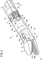
- FIG. 2 is a side view partially shown in cross section of the handle 16 of the manipulator 10.
- the drive unit 22 includes a housing 36, the motor 38 (drive source) arranged in the interior of the housing 36, and a drive gear 40 (pinion gear), which is fixed to an output shaft of the motor 38.
- the drive unit 22 is detachably attached to the rear of the handle main body 20.
- the drive unit 22 is connected to the controller 44 through the cable 42 that includes a power line and a signal line.
- the controller 44 controls the supply of power and driving of the motor 38, and receives electrical power from an external power source.
- a signal corresponding to the operation thereof is transmitted to the controller 44, and the controller 44 controls driving of the motor 38.
- the drive gear 40 which is fixed to the output shaft 38a of the motor 38, is brought into meshing engagement with a driven gear 41 that is disposed inside the body portion 23.
- the motor 38 is rotated, the rotary driving force of the motor 38 is transmitted to the side of the handle main body 20 through the drive gear 40 and the driven gear 41.
- a handle side connector 50 is disposed on the rear of the body portion 23 of the handle main body 20, and a unit side connector 52 is disposed on the rear of the drive unit 22. If the rolling switch 28 is operated in a condition in which the handle side connector 50 and the unit side connector 52 are connected, a signal corresponding to the state of the rolling switch 28 is transmitted to the controller 44 through the connector 54 and the signal line of the cable 42, and under the control of the controller 44, the motor 38 that is mounted in the drive unit 22 is driven.
- the rolling operation of the distal end working unit 14 is effected by an electrical drive provided through the motor 38, whereas the tilting operation and the opening/closing operation of the distal end working unit 14 are effected by a manual drive.
- a structure may be provided in which not only the rolling operation, but also one or both of the tilting operation and the opening/closing operation are effected by an electrical drive.
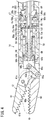
- FIG. 3 is a perspective view showing the distal end working unit 14 which is connected to the distal end of the shaft 18.
- FIG. 4 is a vertical cross-sectional view of the distal end working unit 14.
- the distal end working unit 14 includes the gripper 12 that is capable of being opened and closed, a rotating sleeve 56 of a hollow cylindrical shape, to which the gripper 12 is fixed, and a distal end side fulcrum block 58 that is capable of rotatably supporting the rotating sleeve 56 in an axially rotatable manner at an inner circumferential portion thereof.
- the gripper 12 is made up from a first gripper member 60 and a second gripper member 61.
- the first gripper member 60 and the second gripper member 61 are connected by a pin 63 so as to be capable of rotating about a gripper axis Og.
- the second gripper member 61 is connected through a pin 65a, a link member 62, and a pin 65b to a transmission member 64.
- the transmission member 64 includes a guide tube 64a, a flange 64b disposed on a distal end of the guide tube 64a, and support arms 64c that extend mutually in parallel in the direction of the distal end from edges of the flange 64b.
- the transmission member 64 is arranged so as to be movable in the axial direction in the interior of the rotating sleeve 56.
- a compression spring 66 is arranged between the transmission member 64 and the rotating sleeve 56.
- One end of the compression spring 66 abuts against the flange 64b of the transmission member 64, whereas the other end thereof abuts against a stepped part 56a provided on an inner circumferential portion of the rotating sleeve 56, so that the transmission member 64 normally is elastically biased in the direction of the distal end.
- An end collar 68 is inserted into the transmission member 64 from the distal end side.
- a distal end of the end collar 68 is constituted as an engaging bulge 68a that comes into abutment and engages with a distal end surface of the guide tube 64a of the transmission member 64.
- the end collar 68 is fixed to a distal end of a pull wire 70 that passes through a joint 17 between the distal end working unit 14 and the shaft 18.
- the pull wire 70 forms a member that moves in an advancing and retracting manner in the interior of the shaft 18 and the interior of the distal end working unit 14 responsive to an operation made with respect to the lever 24 of the handle 16.
- the joint 17 that is present between the distal end working unit 14 and the shaft 18 includes a pair of joint pins 73, 74, which are arranged on the tilt axis Oy.
- the pull wire 70 which constitutes part of the opening and closing drive transmission member 80, is capable of advancing and retracting in a direction intersecting the axial direction of the joint pins 73, 74, through a gap provided between the pair of joint pins 73, 74.
- the transmission member 64 When the pull wire 70 is displaced in the direction of the proximal end, the transmission member 64 is pushed toward the proximal end by the end collar 68 that is fixed to the pull wire 70, whereby the transmission member 64 is displaced in the direction of the proximal end in opposition to the biasing force of the compression spring 66.
- the second gripper member 61 which is connected to the link member 62, is rotated in a closing direction with respect to the first gripper member 60. In FIG.
- the second gripper member 61 is shown by an imaginary line, in a state of being closed to a position at which the gripping face 61b of the second gripper member 61 and the gripping face 60b of the first gripper member 60 are placed in contact.
- both of the gripper members may be constituted as movable members.
- a distal end part of a pull rod 91 shown in FIG. 2 is connected to the proximal end of the pull wire 70.
- the pull rod 91 is a tubular member and is arranged by insertion thereof into the interior of the shaft 18.
- the pull wire 70 and the pull rod 91 are capable of relative rotation around a common axis, and are connected in the interior of the shaft 18 so as to be capable of transmitting a tensile force in the direction of the proximal end of the pull rod 91 to the pull wire 70.
- the pull wire 70 which is connected to the pull rod 91, also is displaced in the axial direction to thereby carry out the opening and closing operation of the gripper 12. Further, when the distal end working unit 14 implements the rolling operation, since the pull wire 70 can be rotated with respect to the pull rod 91, the rolling operation of the distal end working unit 14 is not hindered.
- the pull rod 91 is inserted through the interior of a hollow shaft 89, and the proximal end thereof projects outwardly from the proximal end of the hollow shaft 89.
- the lever 24 is connected so as to be capable of swinging with respect to the body portion 23, at a location near the distal end of the body portion 23.
- a distal end of a lever rod 96 which is arranged downwardly of the body portion 23 substantially in parallel with the longitudinal direction of the body portion 23, is connected rotatably near the distal end of the lever 24.
- a hook holder 116 that supports a hook member 118 is fixed to a lower part of the body portion 23.
- a compression spring 98 is arranged between a distal end surface of the hook holder 116 and a distal end expanded diameter portion 96a of the lever rod 96.
- the compression spring 98 normally applies a biasing force to the lever rod 96 in the distal end direction. Consequently, by the elastic force of the compression spring 98, the lever 24, which is connected to the lever rod 96, normally receives a force in a direction to open with respect to the body portion 23.
- a driving force from the lever 24 is transmitted through an intermediate transmission mechanism 100 to the pull rod 91 and the pull wire 70, which constitute the opening and closing drive transmission member 80.
- a condition in which the lever 24 is open with respect to the body portion 23 is regarded as an initial position.
- the pull rod 91 is advanced to a position at which the gripper 12 is in a fully open state.
- the lever rod 96 is displaced in the direction of the proximal end.
- the gripper 12 is operated in a direction to close.
- the distal end of the rotating sleeve 56 is fitted and fixedly attached to the base portion 60c of the first gripper member 60.
- a bevel gear part 56c is disposed on a proximal end of the rotating sleeve 56.
- the gripper 12, the rotating sleeve 56, the transmission member 64, the end collar 68, and the compression spring 66 are capable of integrally rotating relative to the distal end side fulcrum block 58 about the longitudinally directed roll axis Or of the distal end working unit 14.
- the distal end side fulcrum block 58 which is of a hollow cylindrical shape, is capable of being changed in posture with respect to the axial direction of the shaft 18, and rotatably supports the rotating sleeve 56 on an inner circumferential portion thereof.
- the rotating sleeve 56 is connected to the distal end side fulcrum block 58 such that the rotating sleeve 56 is rotatable relative to the distal end side fulcrum block 58, but immovable in the axial direction with respect to the distal end side fulcrum block 58.
- the distal end side fulcrum block 58 and a shaft side fulcrum block 59 are connected together rotatably about the tilt axis Oy by joint pins 73, 74.
- the joint pins 73, 74 are fitted into tongue pieces 58b, 58c disposed on upper and lower parts on the proximal end of the distal end side fulcrum block 58, and into tongue pieces 59b, 59c disposed on upper and lower parts on the distal end of the shaft side fulcrum block 59.
- the shaft side fulcrum block 59 is fixed to the distal end of a hollow shaft main body 19 that constitutes the body portion of the shaft 18 see FIG. 3 ).
- the shaft 18 is constituted from the shaft side fulcrum block 59 and the shaft main body 19.
- the tilt axis Oy is set in the vertical direction. However, the tilt axis Oy may be set in a different direction that intersects the axis of the shaft main body 19.
- a bevel gear 86 is supported rotatably by one of the joint pins 73.
- the teeth 86a of the bevel gear 86 are enmeshed with the bevel gear part 56c provided on the proximal end of the rotating sleeve 56, and with a bevel gear part 88a that is provided on the distal end of a gear member 88.
- the gear member 88 is a hollow cylindrical member, with the pull wire 70 being inserted through a hollow interior portion thereof.
- the rolling operation of the distal end working unit 14 is carried out by transmitting a driving force of the motor 38 through a rolling drive transmission system to the distal end working unit 14.
- the rolling drive transmission system includes, as shown in FIG. 2 , the motor 38, the drive gear 40 that is fixed to the output shaft 38a of the motor 38, the driven gear 41 that is enmeshed with the drive gear 40, and the hollow shaft 89 to which the driven gear 41 is fixed.
- the rolling drive transmission system further includes, as shown in FIG. 4 , the gear member 88 that is fixed to the distal end of the hollow shaft 89, the bevel gear 86 that is enmeshed with the gear member 88, and the rotating sleeve 56 that is enmeshed with the bevel gear 86.
- a rolling drive transmission pipe 131 is constituted by the gear member 88 and the hollow shaft 89. Further, a rotating drive transmission unit, which transmits the rotary driving force from the handle 16 to the distal end working unit 14, is constituted from the rolling drive transmission pipe 131, the bevel gear 86, and the rotating sleeve 56.
- the portion (the pull wire 70) of the opening and closing drive transmission member 80 (the pull wire 70 and the pull rod 91) corresponding to the joint 17 is flexible, with a simple structure, the opening and closing driving force can be transmitted appropriately to the gripper 12. Accordingly, without increasing the complexity of the mechanism of the distal end working unit 14, a structure can be maintained that enables the opening and closing operation as well as the tilting operation of the distal end working unit 14, while also realizing a rolling operation having an unlimited range of rotation.
- a driven pulley 90 is supported rotatably by the other joint pin 74.
- the driven pulley 90 is fixed to an inner surface of the tongue piece 58c of the distal end side fulcrum block 58. Accordingly, when a drive pulley 130 is rotated, the driven pulley 90 and the distal end side fulcrum block 58 are capable of integrally rotating relative to the shaft side fulcrum block 59.
- a tilting operation wire 132 is trained around the driven pulley 90. A portion of the wire 132 is fixed to the driven pulley 90, and the wire 132 passes through the interior of the shaft 18 up to the handle 16.
- the distal end side fulcrum block 58 which is fixed to the driven pulley 90, is rotated integrally with the driven pulley 90.
- the distal end working unit 14 including the distal end side fulcrum block 58, the rotating sleeve 56, and the gripper 12 is rotated about the tilt axis Oy with respect to the shaft 18. This operation is referred to as a tilting operation of the distal end working unit 14.
- the tilting operation of the distal end working unit 14 includes a movement range to a plus side (right side) and to a minus side (left side), respectively.
- the drive pulley 130 which rotates in conjunction with rotation of the tilt wheel 26, is disposed in the interior of the handle main body 20.
- a tilting operation wire 132 is trained around the drive pulley 130.
- An annular space which extends along the axis of the shaft 18, is provided between the inner circumference of the shaft 18 and the outer circumference of the rolling drive transmission pipe 131.
- the wire 132 passes through the interior of the annular space, and is trained around the driven pulley 90 (see FIG. 4 ) at the distal end side of the shaft 18.
- the tilt wheel 26 shown in FIGS. 1 and 2 is rotated by manual operation, and the operating force applied to the tilt wheel 26 is then transmitted to the wire 132 that is trained around the drive pulley 130, thereby driving the wire 132.
- Driving of the wire 132 is output at the distal end of the shaft 18 to rotate the driven pulley 90, whereby the tilting operation of the distal end working unit 14 with respect to the shaft 18 is carried out.
- the manipulator 10 is further equipped with a brake mechanism 134, which restricts movement of the power transmission mechanism between the tilt wheel 26 and the distal end working unit 14, and a brake release mechanism 136 to release the braking action performed by the brake mechanism 134.
- a brake mechanism 134 which restricts movement of the power transmission mechanism between the tilt wheel 26 and the distal end working unit 14, and a brake release mechanism 136 to release the braking action performed by the brake mechanism 134.
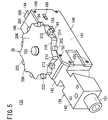
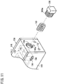
- FIG. 5 is a perspective view of a mechanism unit 133, which is disposed in the handle main body 20.
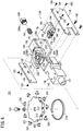
- FIG. 6 is an exploded perspective view of the mechanism unit 133.
- FIG. 7 is a plan view partially shown in cross section of the mechanism unit 133.
- FIG. 8 is a vertical cross-sectional view of the mechanism unit 133.
- the mechanism unit 133 includes a frame 138, the tilt wheel 26 that is attached rotatably to the frame 138, the brake mechanism 134 that is incorporated in the frame 138, and the brake release mechanism 136 that is incorporated in the frame 138.
- the frame 138 is a hollow structure comprising a distal end side structural part 140 including a through hole 139 that penetrates forwardly and rearwardly, and a mechanism box part 142 disposed rearwardly of the distal end side structural part 140, including an interior space 141 that communicates with the through hole 139.
- the shaft 18 is inserted into and fixed to the distal end side of the frame 138.
- the frame 138 includes a frame main body 144 comprising the distal end side structural part 140, and an upper wall, a rear wall, and a bottom wall of the mechanism box part 142, a right side wall plate 146 comprising a right side wall of the mechanism box part 142, and a left side wall plate 148 comprising a left side wall of the mechanism box part 142.
- the right side wall plate 146 and the left side wall plate 148 are fixed to the frame main body 144 by suitable fixing means (e.g., screws 150).
- a cylindrical projecting part 151 which is disposed on the distal end of the frame 138, projects out from the distal end of the casing 29.
- a bearing 154 is arranged through a bearing housing 152 on an upper portion of the frame 138.
- the bearing housing 152 is fixed to the frame 138 by suitable means (e.g., screws 156), and the bearing 154 is mounted on an inner side of the bearing housing 152.
- a wheel shaft 158 which is fixed by a screw 156 to the tilt wheel 26, is supported by the bearing 154. By such a structure, the tilt wheel 26 is supported rotatably with respect to the frame 138.
- the tilt wheel 26 can be rotated about a vertically directed axis of the manipulator 10. Further, with the present embodiment, since the drive pulley 130 is connected through the wheel shaft 158 coaxially with the tilt wheel 26, the tilt wheel 26 and the drive pulley 130 are rotated together in unison.
- the drive pulley 130 is disposed, around which the aforementioned wire 132 is trained.
- the drive pulley 130 is arranged between the bearing 154 and the bearing 160.
- the wire 132 is trained around a first intermediate pulley 162 and a second intermediate pulley 164, which are arranged forwardly of the drive pulley 130, and around a first tension pulley 166 and a second tension pulley 168, which are arranged rearwardly of the drive pulley 130.
- the first intermediate pulley 162 and the second intermediate pulley 164 are supported rotatably on the frame 138 at a position in front of the drive pulley 130, so as to be rotatable about an axis oriented perpendicularly (in a lateral direction of the manipulator 10) with respect to the rotational axis of the drive pulley 130.
- the first intermediate pulley 162 and the second intermediate pulley 164 are juxtaposed in a direction perpendicular to the rotational axis of the drive pulley 130, and are disposed mutually at different heights.
- the first tension pulley 166 and the second tension pulley 168 are arranged at positions separated from one another laterally (in a direction perpendicular to the sheet of FIG. 8 ), and are supported rotatably about axes that are parallel with the rotational axis of the drive pulley 130 (in a vertical direction of the manipulator 10). More specifically, the first tension pulley 166 is supported by a pulley shaft 173 rotatably at a distal end of a pulley holder 171. The second tension pulley 168 also is supported in the same manner as the first tension pulley 166.
- Two adjustment bolts 170 are provided, corresponding respectively to the first tension pulley 166 and the second tension pulley 168.
- a threaded rod 170a of each adjustment bolt 170 is inserted from the rear in a through hole 172 that is provided in a rear wall 138b of the frame 138, and a head 170b of the adjustment bolt 170 abuts against the rear wall 138b.
- the adjustment bolt 170 is rotated, the pulley holder 171 is moved in forward and rearward directions by a screwing action thereof.
- the first tension pulley 166 that is supported by the one of the pulley holders 171 is positionally adjusted, and the tensile force that is applied to the one side portion of the wire 132 between the drive pulley 130 and the driven pulley 90 can be adjusted.
- the second tension pulley 168 that is supported by the other of the pulley holders 171 is positionally adjusted, and the tensile force that is applied to the other side portion of the wire 132 between the drive pulley 130 and the driven pulley 90 can be adjusted.
- the brake mechanism 134 includes a brake rotor 174, which rotates in conjunction with rotation of the tilt wheel 26, a brake shoe 176 that is capable of contacting an outer peripheral part of the brake rotor 174, a slide member 178 to which the brake shoe 176 is attached, and an elastic member 180 that elastically biases or urges the slide member 178.
- the brake rotor 174 is disposed on a power transmission path between the tilt wheel 26 and the distal end working unit 14, and more specifically, as shown in FIG. 8 , is disposed on the wheel shaft 158 adjacent to the drive pulley 130.
- the brake rotor 174 is shaped in the form of a disk, having a first gear 175A provided on an outer circumferential part thereof along a circumferential direction thereof.
- the brake shoe 176 is capable of being advanced and retracted with respect to the brake rotor 174.
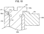
- a second gear 175B which can be enmeshed with the first gear 175A, is disposed on a portion of the brake shoe 176 that confronts the outer circumferential part of the brake rotor 174. As shown in FIG. 9 , the second gear 175B extends in an arcuate shape that conforms to the outer circumferential part of the brake rotor 174.
- the brake shoe 176 is a component that is formed in an L-shape in the illustrated example, and is attached to the slide member 178 by a fixing means (a bolt 182 in the illustrated example).
- the bolt 182 includes a head 182a, a threaded rod 182b on which male threads are formed, and an intermediate part 182c formed between the head 182a and the threaded rod 182b.
- the threaded rod 182b is screw-engaged in a screw hole 179 provided in the slide member 178.
- the outer diameter of the intermediate part 182c is less than the outer diameter of the head 182a and greater than the outer diameter of the threaded rod 182b.
- the intermediate part 182c is arranged in a hole 177a provided in a mounting plate 177 of the brake shoe 176.
- the mounting plate 177 is disposed between the slide member 178 and the head 182a of the bolt 182.
- the outer diameter of the intermediate part 182c is slightly smaller than the inner diameter of the hole 177a provided in the mounting plate 177, and the thickness in the axial direction of the intermediate part 182c is slightly thicker than that of the mounting plate 177. Therefore, gaps are provided, respectively, between the outer circumferential surface of the intermediate part 182c and the inner wall surface that makes up the hole 177a, and between the upper surface of the mounting plate 177 and the lower surface of the head 182a.
- the brake shoe 176 is mounted with a certain amount of play with respect to the slide member 178. Stated otherwise, the brake shoe 176 is mounted on the slide member 178 in a swingable condition, which enables a slight amount of swinging about the axis of the bolt 182 with respect to the slide member 178.
- the slide member 178 is capable of being advanced and retracted with respect to the brake rotor 174, and normally is elastically pressed by the elastic member 180 toward the brake rotor 174.
- the slide member 178 includes a front part 184 constituting a front side thereof, a rear part 186 constituting a rear side thereof, and an intermediate structural part 188 that connects a lower part of the front part 184 with a lower part of the rear part 186.
- a groove 190 that extends in a widthwise direction of the slide member 178 is formed by a rear surface of the front part 184, a front surface of the rear part 186, and an upper surface of the intermediate structural part 188.
- An insertion hole 192 which opens rearwardly, is formed centrally in the widthwise direction of the rear part 18b. One end side of the elastic member 180 is inserted in the insertion hole 192.
- pins 194 are formed that project out, respectively, at front and back spaced positions.
- the pins 194 are inserted slidably in forward and rearward directions in long holes 196 that are formed and extend longitudinally in the right side wall plate 146 and the left side wall plate 148 of the frame 138.
- the elastic member 180 is constituted from a coil spring.
- a coil spring instead of a coil spring, another form of spring (e.g., a plate spring, a torsion spring, etc.) or a rubber body may be used.
- an insertion hole 198 is disposed having a size that allows the elastic member 180 to be inserted therethrough.
- a retaining member 200 that holds and presses the elastic member 180 is installed in the insertion hole 198.
- the elastic member 180 is inserted into the frame 138 in which the slide member 178 is disposed, through the insertion hole 198 from a rearward side of the frame 138. Thereafter, by installing the retaining member 200 in the insertion hole 198, the elastic member 180 can be arranged in a compressed state between the retaining member 200 and the slide member 178.
- the retaining member 200 is installed in the insertion hole 198 so as to be capable of changing the amount of compression of the elastic member 180. More specifically, in the present embodiment, female threads 198a are formed on the inner circumferential surface of the insertion hole 198, whereas male threads 200a are formed on the outer circumference of the retaining member 200. Therefore, the retaining member 200 can be screw-engaged in the insertion hole 198. The amount of compression of the elastic member 180 changes corresponding to the amount by which the retaining member 200 is screwed in, whereby the pressing force of the brake shoe 176 applied with respect to the brake rotor 174 can be adjusted.
- the first gear 175A provided on the brake rotor 174 and the second gear 175B provided on the brake shoe 176 engage with each other. Therefore, compared to a situation in which the outer circumference of the brake rotor 174 and the brake shoe 176 are both smooth surfaces, due to intermeshing of the gears, a stronger braking force can be obtained. Consequently, even if the elastic force of the elastic members 180 is small, since a sufficient braking force can be obtained, the operating force when braking is released in opposition to the elastic force of the elastic member 180 can effectively be reduced. Accordingly, the manipulator 10 with superior ease of operation can be provided.
- the slide member 178 which is elastically pressed by the elastic member 180 toward the brake rotor 174 and which is capable of being advanced and retracted with respect to the brake rotor 174, is provided.
- the brake shoe 176 is a component that is fixed to the slide member 178.
- the brake shoe 176 is not a member that is formed integrally on a component that is pressed by the elastic member 180, but rather, is a member that is attached to the slide member 178 that is constituted as a separate element. Therefore, in case there is a design modification to the brake shoe 176, since only the brake shoe 176 needs to be modified while leaving the slide member 178 intact, design changes can easily be handled.
- the second gear 175B extends in an arcuate shape conforming to the outer circumference of the brake rotor 174, and the brake shoe 176 is mounted on the slide member 178 in a state of being capable of swinging slightly with respect to the slide member 178.
- the angle of the brake shoe 176 changes automatically to facilitate meshing of the first gear 175A and the second gear 175B over a predetermined range in the circumferential direction. Accordingly, the brake shoe 176 is aligned and centered automatically with respect to the brake rotor 174, so that a suitable braking force can be exhibited.
- the insertion hole 198 is disposed in the rear wall 138b of the frame 138, having a size that enables insertion of the elastic member 180 therethrough, and the retaining member 200 is installed in the insertion hole 198.
- assembly and removal of the elastic member 180 through the insertion hole 198 can easily and swiftly be carried out.
- the depth at which the retaining member 200 is screwed in with respect to the insertion hole 198 the amount of compression of the elastic member 180 can be changed, and the force at which the brake shoe 176 presses against the brake rotor 174 can easily be adjusted.
- a screw-engagement structure is provided, the position of the retaining member 200 can easily be adjusted very finely.
- the brake release mechanism 136 includes release buttons 202 (release operating units) provided on the tilt wheel 26, and lever mechanisms 204 disposed in the tilt wheel 26 and which are pressed by the release buttons 202 being displaced inwardly.
- release buttons 202 release operating units
- lever mechanisms 204 are operated, whereby the braking action applied by the brake mechanism 134 is released.
- the release buttons 202 are disposed in a plurality with intervals therebetween in the circumferential direction on the outer circumference of the tilt wheel 26, in a state of projecting radially outward from the outer circumference. With the present embodiment, nine release buttons 202 are arranged at equal intervals along the outer circumference of the tilt wheel 26.
- the tilt wheel 26 includes a disk part 206 to which the wheel shaft 158 is fixed at the center, and a circumferential edge part 208 disposed on the outer edge of the disk part 206 and which projects downwardly from the disk part 206. As shown in FIG. 8 , an annular recess 210 is formed on an inner side of the circumferential edge part 208. Further, as shown in FIG. 6 , on the circumferential edge part 208, plural button holes 212 (nine are shown in the drawing) are circumferentially disposed at intervals, the button holes 212 penetrating radially through the tilt wheel 26.
- the release buttons 202 are arranged movably in radial directions respectively in the button holes 212.
- the release buttons 202 are inserted from an inner side of the circumferential edge part 208.
- Plural convex portions 214 and plural concave portions 216 are formed alternately along the circumferential direction on the circumferential edge part 208.
- the plural release buttons 202 are disposed respectively in the plural concave portions 216.
- the concave portions 216 are arcuately shaped in the illustrated example.
- Engagement tabs 203 which project in substantially opposite directions mutually, are disposed on one end side of each of the release buttons 202.
- the engagement tabs 203 function as slip-out prevention parts, which prevent slipping-out of the release buttons 202 from the tilt wheel 26.
- a backup member 218 is provided that presses the release buttons 202 outwardly.
- the backup member 218 is a curved plate spring formed in a ring shape having an outer diameter greater than the inner diameter of the circumferential edge part 208 in a natural state, such that in a state of being arranged in the interior of the annular recess 210 of the circumferential edge part 208, both ends of the backup member 218 overlap to form a simple annular shape.
- the release buttons 202 are pressed in radially outward directions of the tilt wheel 26 by the backup member 218, which is arranged on the inner side thereof. As a result, the release buttons 202 are prevented from dropping out inwardly from the button holes 212 that are formed in the circumferential edge part 208 of the tilt wheel 26.
- the lever mechanisms 204 are disposed as a pair.
- first lever mechanism 204A one of the lever mechanisms 204 will be referred to as a "first lever mechanism 204A”
- second lever mechanism 204B the other of the lever mechanisms 204 will be referred to as a "second lever mechanism 204B”.
- the lever mechanisms 204 include levers 220 that are pressed and rotated on an inner side of the tilt wheel 26 accompanying inward movement of the release buttons 202, shafts 222a, 222b disposed on the respective levers 220, and cams 224a, 224b that move about the respective shafts 222a, 222b.
- the levers 220 have curved shapes along the circumferential edge part 208 of the tilt wheel 26, and include arcuately-shaped pressed members 221 provided on outer circumferential sides thereof.
- the radius of curvature of the pressed members 221 is substantially the same or slightly smaller than the inner diameter of the backup member 218 in a state of being arranged inside the circumferential edge part 208.
- the levers 220 can receive pressing forces from the release buttons 202, which are positioned on the outer side thereof, within an angular range over which the pressed members 221 are formed.
- the two levers 220 are of the same shape, and are arranged in laterally symmetrical positions.
- a base portion 220a is formed on a side opposite from a location on which the pressed member 221 is formed, and to the base portion 220a, a shaft 222a, 222b is connected in a downwardly projecting manner.
- the two shafts 222a, 222b are supported rotatably in two shaft holes 225, respectively, which are formed in an upper wall portion of the frame 138.
- the shafts 222a, 222b, which are connected to the respective two levers 220, are of mutually different lengths.
- the shaft 222a of the first lever mechanism 204A is longer than the shaft 222b of the second lever mechanism 204B.
- the cams 224a, 224b are formed respectively on lower ends of the shafts 222a, 222b. As shown in FIG. 8 , the cams 224a, 224b are arranged in the interior of the frame 138. Below, in cases where the two cams 224a, 224b are distinguished from each other, the cam 224a disposed on the first lever mechanism 204A will be referred to as a "first cam 224a”, and the cam 224b disposed on the second lever mechanism 204B will be referred to as a "second cam 224b".
- the first cam 224a is arranged downwardly from the second cam 224b, and so that the two cams 224a, 224b do not interfere with each other, the two cams 224a, 224b are disposed in mutually overlapping positions as viewed in plan.
- the second cam 224b has a partially recessed shape such that, at a time of being operated within a movable range thereof, the second cam 224b does not interfere with the shaft 222a of the first lever mechanism 204A.
- the two cams 224a, 224b are arranged within the groove 190 that is formed in the slide member 178, in a state of abutment against a central region in the widthwise direction of a front surface of the rear part 186 of the slide member 178.
- the slide member 178 which is biased elastically by the elastic member 180 toward the brake rotor 174, presses against the two cams 224a, 224b.
- the pressing force received by the cams 224a, 224b acts in a direction to open the two lever mechanisms 204.
- the first lever mechanism 204A is operated based on an operation applied with respect to part of the release buttons 202 (in the state shown in FIG 7 , the release buttons 202a, 202b) from among the plurality of release buttons 202.
- the second lever mechanism 204B is operated based on an operation applied with respect to other part of the release buttons 202 (in the state shown in FIG 7 , the release buttons 202c, 202d) from among the plurality of release buttons 202. Accordingly, by operating either one of the pair of lever mechanisms 204, the braking action performed by the brake mechanism 134 is released.
- the release buttons 202 provided on the tilt wheel 26 are pressed inwardly.
- the release buttons 202 are pressed, at least one of the two lever mechanisms 204 (i.e., the levers 220) is pressed through the backup member 218, which is arranged on the inner side of the tilt wheel 26.
- the lever 220 of the first lever mechanism 204A is pressed, and the lever 220 is rotated inwardly about the shaft 222a.
- the lever 220 of the second lever mechanism 204B is pressed, and the lever 220 is rotated inwardly about the shaft 222b.
- the cams 224a, 224b press and displace the slide member 178 in an opposite direction to the brake rotor 174 (rearwardly of the manipulator 10 in the illustrated example) in opposition to the elastic force of the elastic member 180.
- the brake shoe 176 that is mounted on the slide member 178 also is displaced in unison with the slide member 178.
- any one of the two cams 224a, 224b comes into contact with the central region in the widthwise direction of the slide member 178. Consequently, even in the case that only one of the two lever mechanisms 204 is rotated, since either one of the cams 224a, 224b presses the central region in the widthwise direction of the slide member 178, the slide member 178 can be displaced smoothly.
- the brake shoe 176 separates away from the brake rotor 174, and the brake rotor 174 assumes a state in which rotation thereof is enabled. More specifically, a state is brought about in which the braking action performed by the brake mechanism 134 is released. Consequently, under a condition in which the release buttons 202 are pressed, the operating force is applied to the tilt wheel 26 in the direction of rotation of the tilt wheel 26, whereby the tilt wheel 26 can be rotated, and a tilting operation can be effected to the gripper 12. In this case, since the release buttons 202 rotate integrally with the tilt wheel 26, while the inwardly-pressed condition of the release buttons 202 is maintained, the rotating operation of the tilt wheel 26 can easily be carried out.
- the brake release mechanism 136 since the release buttons 202 for releasing the braking action are provided on the tilt wheel 26, which is operated to carry out a tilting operation on the gripper 12, the operator of the manipulator 10 can easily contact and touch the release buttons 202 with the same hand that operates the tilt wheel 26. Accordingly, the braking action performed by the brake mechanism 134 can easily and swiftly be released with one hand. More specifically, the brake releasing operation and the rotating operation of the tilt wheel 26 can both be carried out easily and reliably with one hand.
- the brake release mechanism 136 can be constructed compactly, and can contribute to a reduction in size and weight of the manipulator 10 in which the brake mechanism 134 is incorporated.
- the lever mechanisms 204 include the levers 220 that are pressed and rotated on an inner side of the tilt wheel 26 accompanying inward movement of the release buttons 202, the shafts 222a, 222b disposed on the levers 220, and the cams 224a, 224b that are moved about the shafts 222a, 222b.
- the cams 224a, 224b are operated so as to cause the brake shoe 176 to separate away from the brake rotor 174, whereby the braking action is released. Owing to such a structure, by appropriately setting the lever ratio of the lever mechanisms 204, releasing of the braking action can be implemented with a low operating force.
- the brake releasing operation can be carried out more easily and reliably.
- the release buttons 202 are disposed displaceably in inward and outward directions on the outer circumference of the tilt wheel 26.
- the tilt wheel 26 can be rotated, a series of operations including the brake-releasing operation and thereafter the rotating operation can smoothly be carried out without interruption.
- the release buttons 202 are disposed respectively at a plurality of different positions in the circumferential direction on the outer circumference of the tilt wheel 26. According to such a structure, since not only one but multiple release buttons 202 are provided, releasing of the braking operation can be performed easily merely by the user selecting and pressing any of the release buttons 202 that can easily be gripped.
- plural convex portions 214 and plural concave portions 216 are each formed alternately along the circumferential direction on the outer circumferential part of the tilt wheel 26, and the plural release buttons 202 are disposed respectively in the plural concave portions 216.
Description
- The present invention relates to a brake release mechanism and a medical manipulator provided with the same for releasing a braking action performed by a brake mechanism, which limits movement of a mechanism linked operatively with a working unit, and by which operations with respect to a rotary operating member are transmitted mechanically.
- In an endoscopic surgical operation (also referred to as "laparoscopic surgery"), a plurality of holes are punctured in the abdomen or the like of a patient, trocars (cylindrical instruments) are inserted through the holes, and a laparoscope (camera) and a plurality of forceps are inserted into the body cavity via each of the trocars. Grippers for gripping biological tissue, scissors, and blades of an electrosurgical knife may be mounted to the tip of the forceps as an end effector.
- The laparoscope and the forceps are inserted into the body cavity, and an operator then operates by operating the forceps while viewing a state of the inner portion of the abdominal cavity, which is shown on a monitor that is connected to the laparoscope. Since the surgical procedure does not require a laparotomy, the burden on the patient is decreased, which reduces the number of days for postoperative recovery and the number of days until the patient leaves the hospital. For this reason, the fields that such an operative method can be applied to are expected to expand.
- Other than typical forceps that are not provided with joints at distal end portions thereof, as forceps that are used in an endoscopic surgical operation, forceps referred to as a medical manipulator have been developed that are provided with joints at distal end portions and which can carry out a rolling operation or a tilting operation of an end effector (for example, refer to Japanese Patent No.
4391762 -
US 2010/0170931 A1 discloses a surgical instrument including a handle having an elongated tubular member extending distally from the handle and one or more end effectors mounted on the distal end of the elongate tubular member. A driver is movably mounted within the handle and elongate tubular member in order to operate the end effectors. The surgical instrument includes an energy storage mechanism for storing and providing energy to move the driver and thereby actuate the surgical instrument. The actuation mechanism is operable on the energy storage mechanism to control the rate of release of the energy stored in the energy storage mechanism. -
US 2008/0255608 A1 discloses surgical or diagnostic tools. The tools include a proximally-located actuator for the operation of a distal end effector, as well as proximally-located actuators for articulational and rotational movements of the end effect. -
WO 2012/006306 A2 , representing the closest prior art, discloses a medical manipulator with a shaft and an end effector which can be tilted with respect to the shaft axis. - Tilting can be initiated by rotating a dedicated tilt actuation wheel provided on the handle.
- The disclosure further shows a combined brake and brake release mechanism that is located distally from the tilt actuation wheel on a proximal portion of the shaft.
- Incidentally, in an operation using a medical manipulator equipped with a tiltable end effector, cases occur in which a biological tissue (e.g., an organ) is pressed by the end effector which is inserted into the living body. In this case, assuming that tilting of the end effector is carried out by a motor drive, due to rotational resistance of the motor and the presence of the gears or the like, even if a reaction force is received by the end effector from the living tissue, a change in the angle of the end effector caused by such a reaction force is suppressed. However, if an operating member (operating dial) is manually operated to carry out tilting of the end effector, in the event that the living tissue is pressed by the end effector, the angle of the end effector still tends to be changed by such a reaction force.
- In order to prevent such an occurrence, it may be possible to ensure that the end effector does not undergo movement by holding the operating member firmly with hand. However, such an action is troublesome, and carrying out procedures is difficult. Further, for ensuring that the end effector does not undergo movement due to such reaction forces, it may be considered to arrange a worm gear in the power transmission path between the operating member and the end effector. However, when such a worm gear is used, it becomes necessary for the operating member to be turned many times in order to change the angle of the end effector, and responsiveness to operations of the operating member is deteriorated.
- Thus, it has been considered to provide a brake mechanism for restricting movement of the power transmission mechanism for transmitting power to the end effector from the operating member, together with providing a brake release mechanism to release the braking action performed by the brake mechanism. Further, in this case, a release button, which is operated by the user, is disposed on the brake release mechanism.
- However, in the case of such a structure, for changing the angle of the end effector, it is necessary for a rotary operating member to be rotated while simultaneously operating the release button. Therefore, in order to change the angle of the end effector, the user is required to operate the release button with one hand, and to operate the operating member with the other hand. alternatively, even in the case that the release button is arranged in proximity to the operating member so that the user can operate both the release button and the operating member with one hand, operation of both the release button and the operating member with one hand is not easily performed, and operability is adversely affected.
- The present invention has been devised while taking into consideration the aforementioned problems, and has the object of providing a medical manipulator equipped with a brake release mechanism which is capable of easily and swiftly releasing a braking action performed by a brake mechanism, even with one hand. The present invention is characterized by a medical manipulator according to
claim 1, equipped with a distal end working unit on a distal end of a shaft that extends from a handle, is the distal end working unit being capable of being tilted with respect to the shaft, the medical manipulator being constituted so as to mechanically transmit an input operation with respect to a tilt operating member provided on the handle, to thereby tiltably operate the distal end working unit, and further being equipped with a brake release mechanism. The brake release mechanism includes a release operating unit disposed on the tilt operating member, and a lever mechanism, at least a portion of which is arranged on an inner side of the tilt operating member, and which is pressed accompanying inward movement of the release operating unit. The lever mechanism undergoes movement accompanying an operation performed with respect to the release operating unit, whereby a braking action implemented by a brake mechanism is released. The tilt operating member is disposed rotatably on the handle. Further, under a condition in which the release operating unit is pressed inwardly, the tilt operating member is rotated to thereby tilt the distal end working unit. - In accordance with the medical manipulator, both the release button and the tilt operating member can be operated with one hand, and ease of operation can be enhanced.
- The brake release mechanism of the present invention enables a braking action performed by the brake mechanism to be released easily and swiftly even with one hand. In accordance with the medical manipulator of the present invention, both the release button and the operating member can be operated with one hand, whereby ease of operation can be enhanced.
- According to the above structure, since the release operating unit can easily be touched while the operating member is operated, a braking action performed by the braking mechanism can easily and swiftly be released with one hand. Further, since the lever, which is pressed accompanying an operation performed with respect to the operating member, is arranged on the inner side of the operating member, the brake release mechanism can be constructed compactly, and can contribute to a reduction in size and weight of an apparatus in which the brake mechanism is incorporated.
- The brake mechanism may be equipped with a brake rotor that operates in conjunction with rotation of the operating member, and a brake shoe that is capable of contacting an outer circumference of the brake rotor, wherein based on an elastic force of an elastic member, the brake shoe is pressed against the brake rotor to thereby generate a braking force. The lever mechanism may include a lever that is pressed and rotates on the inner side of the operating member accompanying inward movement of the release operating unit, a shaft on which the lever is disposed, and a cam that operates about the shaft. In this case, accompanying an operation performed with respect to the release operating unit, the cam causes the brake shoe to move in a direction away from the brake rotor in opposition to the elastic force, thereby releasing the braking action. According to such a structure, by appropriately setting the lever ratio of the lever mechanism, releasing of the braking action can be implemented with a low operating force.
- In the above-described brake release mechanism, the lever mechanism may include a pair of lever mechanisms, the release operating unit may include a plurality of release operating units, one of the lever mechanisms may be actuated based on an operation carried out with respect to part of the plurality of release operating units, another of the lever mechanisms may be actuated based on an operation carried out with respect to other part of the plurality of release operating units, and the braking action may be released by actuating at least one of the pair of lever mechanisms. According to this structure, since the braking action can be released by actuating either one of the lever mechanisms, the brake releasing operation can be carried out more easily and reliably.
- In the above-described brake release mechanism, the cam provided on one of the lever mechanisms, and the cam provided on the other of the lever mechanisms may be disposed in mutually overlapping positions as viewed from an axial direction of the shaft. In accordance with this structure, the pair of lever mechanisms can be arranged compactly in a narrow space.
- In the above-described brake release mechanism, accompanying operation of at least one of the pair of lever mechanisms, at least one of the cams may press a central region in a widthwise direction of the slide member on which the brake shoe is disposed. By this structure, the slide member can be displaced smoothly.
- In the above-described brake release mechanism, the release operating unit may be disposed displaceably in inward and outward directions on the outer circumference of the operating member. In accordance with this structure, since the braking action can be released by press-gripping the release operating unit inwardly, and in this condition, the operating member can be rotated, a series of operations including the brake-releasing operation and thereafter the rotating operation can smoothly be carried out.
- In the above-described brake release mechanism, a slip-out prevention part may be provided on the release operating unit to prevent slipping out of the releasing operating unit from the operating member, and a backup member, which presses the release operating unit outwardly, may be provided on the inner side of the operating member. By this structure, the release operating unit can be prevented from slipping out when placed in a position that does not correspond to the lever.
- In the above-described brake release mechanism, the release operating unit may include plural release operating units that are provided at different positions circumferentially on the outer circumference of the operating member. According to such a structure, since not only one but multiple release operating units are provided, releasing of the braking operation can be easily performed merely by the user selecting and pressing any releasing operating unit that can easily be gripped.
- In the above-described brake release mechanism, plural convex portions and plural concave portions may be formed alternately along the circumferential direction on the outer circumference of the operating member, the plural release operating units being disposed respectively in the plural concave portions. By such a structure, since the release operating units are arranged at positions where they are not easily pressed by accidentally touching the rotary operating member, unintentional releasing of the braking action can be inhibited.
-
-
FIG. 1 is a perspective view with partial omission of a medical manipulator according to an embodiment of the present invention; -
FIG. 2 is a side view partially shown in cross section of the medical manipulator illustrated inFIG. 1 ; -
FIG. 3 is a perspective view of a distal end working unit of the medical manipulator illustrated inFIG. 1 ; -
FIG. 4 is a vertical cross-sectional view of the distal end working unit; -
FIG. 5 is a perspective view of a mechanism unit; -
FIG. 6 is an exploded perspective view of the mechanism unit; -
FIG. 7 is a plan view partially shown in cross section of the mechanism unit; -
FIG. 8 is a vertical cross-sectional view of the mechanism unit; -
FIG. 9 is an exploded perspective view of a slide member, a brake shoe, and a bolt; -
FIG. 10 is a cross-sectional view with partial omission of the slide member, the brake shoe, and the bolt; -
FIG. 11 is a perspective view as seen from a proximal end side of the mechanism unit; and -
FIG. 12 is a perspective view of a lever mechanism. - Hereinafter, a preferred embodiment of a brake release mechanism and a medical manipulator according to the present invention will be described in detail below with reference to the accompanying drawings.
-
FIG. 1 is a perspective view with partial omission of a medical manipulator 10 (hereinafter referred to as a "manipulator 10") according to an embodiment of the present invention. Themanipulator 10 is a medical device that grasps a needle, a suture thread, or a part of the living body or that touches the living body using a gripper 12 (end effector) provided at the distal end thereof, and carries out a predetermined treatment. Themanipulator 10 is constituted as a needle driver that is capable of grasping a medical needle (a curved needle or the like) with thegripper 12 which is disposed on the distal end thereof. - The
manipulator 10 is equipped with a distal end working unit 14 (working unit) including thegripper 12, ahandle 16 that drives thegripper 12, and ashaft 18 that interconnects thegripper 12 and thehandle 16. Thegripper 12 is a portion that carries out a surgical treatment, and in the illustrated example, thegripper 12 includes first andsecond gripper members - The posture of the distal
end working unit 14 including thegripper 12 can be changed at a plurality of degrees of freedom with respect to theshaft 18. In the present embodiment, the distalend working unit 14 can carry out a "tilting operation" (swinging operation) in which the distalend working unit 14 is operated to tilt in left and right directions with respect to an axis of theshaft 18, and a "rolling operation" in which the distalend working unit 14 is rotated about the axis in the longitudinal direction of the distalend working unit 14. Instead of swinging in left and right directions, the tilting operation may be an operation in which the distalend working unit 14 is operated in a tilting manner in upward and downward directions with respect to the axis of theshaft 18. - The
shaft 18 is an elongated and small diameter tubular member. A plurality of members configured to make up a power transmission mechanism are inserted through and arranged in a hollow portion of theshaft 18. Such a power transmission mechanism transmits, from thehandle 16 to the distalend working unit 14, power that is necessary for carrying out the opening and closing operation of thegripper 12, and the rolling operation and the tilting operation of the distalend working unit 14. - The
handle 16 includes a handlemain body 20 including a plurality of operating units, and adrive unit 22 including amotor 38, thedrive unit 22 being capable of being attached to and detached from the handlemain body 20. When themotor 38 is driven in a state in which thedrive unit 22 is mounted on the handlemain body 20, a driving force from themotor 38 is transmitted to the distalend working unit 14. Thus, the form of use thereof can be one in which, concerning a manipulator main body, which includes the handlemain body 20, theshaft 18, and the distalend working unit 14, the manipulator main body can be discarded after being used a predetermined number of times, whereas thedrive unit 22 can be used repeatedly many times by changing the manipulator main body that is connected to thedrive unit 22. - The handle
main body 20 comprises abody portion 23 that is connected to a proximal end of theshaft 18, alever 24 constituting an opening and closing operating unit that is provided on thebody portion 23, a tilt wheel 26 (operating member) constituting a tilt operating unit that is provided on thebody portion 23, and a rollingswitch 28 constituting a rolling operating unit that is provided on thebody portion 23. - The
body portion 23 makes up a part that is gripped by a user when themanipulator 10 is used. In the present embodiment, thebody portion 23 is constituted in the form of a stick that extends over a certain length in the axial direction of theshaft 18. Thebody portion 23 includes acasing 29 made up from anupper cover 29a and alower cover 29b, with drive components such as pulleys, gears, wires, etc., being arranged in the interior of thecasing 29. - A
lever 24 for performing an opening and closing operation of thegripper 12 is disposed on a lower part of thebody portion 23, and is mounted swingably upward and downward about the distal end side thereof which serves as a support point. According to the present embodiment, thelever 24 is constructed as a manual operating element, in which an opening and closing operation of thegripper 12 is carried out by mechanically transmitting to thegripper 12 of the distalend working unit 14 an operating force applied with respect to thelever 24. More specifically, a structure is provided in which thegripper 12 is opened when thelever 24 is opened, and thegripper 12 is closed when thelever 24 is closed. - The
tilt wheel 26 for carrying out a tilting operation of the distalend working unit 14 is disposed near the center in the longitudinal direction of thebody portion 23. Thetilt wheel 26 is constituted as a manual operating element, and thetilt wheel 26 is partially exposed fromopenings 27 provided on left and right sides of thecasing 29. When thetilt wheel 26 is operated by being rotated, the operating force applied thereto is transmitted mechanically to the distalend working unit 14 through a tilting operation power transmission system, which is disposed internally in thehandle 16 and theshaft 18, whereupon the distalend working unit 14 is tilted in a non-parallel direction (in left and right directions or upward and downward directions) with respect to the axis of theshaft 18. - The rolling
switch 28 for carrying out a rolling operation of the distalend working unit 14 is disposed on an upper portion in the vicinity of the front end of thebody portion 23. In the present embodiment, the rollingswitch 28 is constituted as an electrical operating element, which supplies an operating command to themotor 38 through acontroller 44. - When the rolling
switch 28 is pressed, a signal corresponding to the pressed position is transmitted to thecontroller 44 through aconnector 54 and acable 42, and under the control of thecontroller 44, themotor 38 is driven and a driving force from themotor 38 is transmitted to the distalend working unit 14, whereby the distalend working unit 14 is rotated about the longitudinal axis of the distalend working unit 14. In the present embodiment, the distalend working unit 14 is rotated clockwise when a right-hand part of the rollingswitch 28 is pressed, and the distalend working unit 14 is rotated counterclockwise when a left-hand part of the rollingswitch 28 is pressed. -
FIG. 2 is a side view partially shown in cross section of thehandle 16 of themanipulator 10. As shown inFIG. 2 , thedrive unit 22 includes ahousing 36, the motor 38 (drive source) arranged in the interior of thehousing 36, and a drive gear 40 (pinion gear), which is fixed to an output shaft of themotor 38. Thedrive unit 22 is detachably attached to the rear of the handlemain body 20. - The
drive unit 22 is connected to thecontroller 44 through thecable 42 that includes a power line and a signal line. Thecontroller 44 controls the supply of power and driving of themotor 38, and receives electrical power from an external power source. When the rollingswitch 28 is operated, a signal corresponding to the operation thereof is transmitted to thecontroller 44, and thecontroller 44 controls driving of themotor 38. - Upon attachment of the
drive unit 22 to thebody portion 23 of the handlemain body 20, thedrive gear 40, which is fixed to theoutput shaft 38a of themotor 38, is brought into meshing engagement with a drivengear 41 that is disposed inside thebody portion 23. In this condition, when themotor 38 is rotated, the rotary driving force of themotor 38 is transmitted to the side of the handlemain body 20 through thedrive gear 40 and the drivengear 41. - As shown in
FIG. 2 , ahandle side connector 50 is disposed on the rear of thebody portion 23 of the handlemain body 20, and aunit side connector 52 is disposed on the rear of thedrive unit 22. If the rollingswitch 28 is operated in a condition in which thehandle side connector 50 and theunit side connector 52 are connected, a signal corresponding to the state of the rollingswitch 28 is transmitted to thecontroller 44 through theconnector 54 and the signal line of thecable 42, and under the control of thecontroller 44, themotor 38 that is mounted in thedrive unit 22 is driven. - In the
manipulator 10 according to the present embodiment, only the rolling operation of the distalend working unit 14 is effected by an electrical drive provided through themotor 38, whereas the tilting operation and the opening/closing operation of the distalend working unit 14 are effected by a manual drive. However, in a modification of themanipulator 10, a structure may be provided in which not only the rolling operation, but also one or both of the tilting operation and the opening/closing operation are effected by an electrical drive. -
FIG. 3 is a perspective view showing the distalend working unit 14 which is connected to the distal end of theshaft 18.FIG. 4 is a vertical cross-sectional view of the distalend working unit 14. As shown inFIGS. 3 and4 , the distalend working unit 14 includes thegripper 12 that is capable of being opened and closed, a rotatingsleeve 56 of a hollow cylindrical shape, to which thegripper 12 is fixed, and a distal endside fulcrum block 58 that is capable of rotatably supporting therotating sleeve 56 in an axially rotatable manner at an inner circumferential portion thereof. - The
gripper 12 is made up from afirst gripper member 60 and asecond gripper member 61. Thefirst gripper member 60 and thesecond gripper member 61 are connected by apin 63 so as to be capable of rotating about a gripper axis Og. An object to be gripped, for example, a needle or the like, is gripped by thefirst gripper member 60 and thesecond gripper member 61. - The
second gripper member 61 is connected through apin 65a, alink member 62, and apin 65b to atransmission member 64. Thetransmission member 64 includes aguide tube 64a, aflange 64b disposed on a distal end of theguide tube 64a, and supportarms 64c that extend mutually in parallel in the direction of the distal end from edges of theflange 64b. Thetransmission member 64 is arranged so as to be movable in the axial direction in the interior of therotating sleeve 56. - A
compression spring 66 is arranged between thetransmission member 64 and therotating sleeve 56. One end of thecompression spring 66 abuts against theflange 64b of thetransmission member 64, whereas the other end thereof abuts against a steppedpart 56a provided on an inner circumferential portion of therotating sleeve 56, so that thetransmission member 64 normally is elastically biased in the direction of the distal end. - An
end collar 68 is inserted into thetransmission member 64 from the distal end side. A distal end of theend collar 68 is constituted as anengaging bulge 68a that comes into abutment and engages with a distal end surface of theguide tube 64a of thetransmission member 64. Theend collar 68 is fixed to a distal end of apull wire 70 that passes through a joint 17 between the distalend working unit 14 and theshaft 18. - The
pull wire 70 forms a member that moves in an advancing and retracting manner in the interior of theshaft 18 and the interior of the distalend working unit 14 responsive to an operation made with respect to thelever 24 of thehandle 16. The joint 17 that is present between the distalend working unit 14 and theshaft 18 includes a pair ofjoint pins pull wire 70, which constitutes part of the opening and closingdrive transmission member 80, is capable of advancing and retracting in a direction intersecting the axial direction of thejoint pins joint pins - When the
pull wire 70 is displaced in the direction of the proximal end, thetransmission member 64 is pushed toward the proximal end by theend collar 68 that is fixed to thepull wire 70, whereby thetransmission member 64 is displaced in the direction of the proximal end in opposition to the biasing force of thecompression spring 66. Accompanying displacement of thetransmission member 64 toward the proximal end, thesecond gripper member 61, which is connected to thelink member 62, is rotated in a closing direction with respect to thefirst gripper member 60. InFIG. 4 , thesecond gripper member 61 is shown by an imaginary line, in a state of being closed to a position at which thegripping face 61b of thesecond gripper member 61 and thegripping face 60b of thefirst gripper member 60 are placed in contact. - From the state of being closed to the position at which the
gripping face 61b of thesecond gripper member 61 and thegripping face 60b of thefirst gripper member 60 are in contact, when thepull wire 70 and theend collar 68 are advanced, since thetransmission member 64 is urged forward by the elastic force of thecompression spring 66, thefirst gripper member 60 rotates through thelink member 62 in a direction to open with respect to thesecond gripper member 61, and is restored to its original state. This operation is referred to as an opening and closing operation of thegripper 12. - In the present embodiment, although concerning the
gripper 12, a case has been described in which thefirst gripper member 60 is constituted as a fixed member and thesecond gripper member 61 is constituted as a movable member, both of the gripper members may be constituted as movable members. - A distal end part of a
pull rod 91 shown inFIG. 2 is connected to the proximal end of thepull wire 70. Thepull rod 91 is a tubular member and is arranged by insertion thereof into the interior of theshaft 18. Thepull wire 70 and thepull rod 91 are capable of relative rotation around a common axis, and are connected in the interior of theshaft 18 so as to be capable of transmitting a tensile force in the direction of the proximal end of thepull rod 91 to thepull wire 70. - Due to being constructed in this manner, when the
pull rod 91 is displaced in the axial direction, thepull wire 70, which is connected to thepull rod 91, also is displaced in the axial direction to thereby carry out the opening and closing operation of thegripper 12. Further, when the distalend working unit 14 implements the rolling operation, since thepull wire 70 can be rotated with respect to thepull rod 91, the rolling operation of the distalend working unit 14 is not hindered. - As shown in
FIG. 2 , thepull rod 91 is inserted through the interior of ahollow shaft 89, and the proximal end thereof projects outwardly from the proximal end of thehollow shaft 89. On the other hand, at a distal end part thereof, thelever 24 is connected so as to be capable of swinging with respect to thebody portion 23, at a location near the distal end of thebody portion 23. A distal end of alever rod 96, which is arranged downwardly of thebody portion 23 substantially in parallel with the longitudinal direction of thebody portion 23, is connected rotatably near the distal end of thelever 24. - A
hook holder 116 that supports ahook member 118 is fixed to a lower part of thebody portion 23. Acompression spring 98 is arranged between a distal end surface of thehook holder 116 and a distal end expandeddiameter portion 96a of thelever rod 96. Thecompression spring 98 normally applies a biasing force to thelever rod 96 in the distal end direction. Consequently, by the elastic force of thecompression spring 98, thelever 24, which is connected to thelever rod 96, normally receives a force in a direction to open with respect to thebody portion 23. A driving force from thelever 24 is transmitted through anintermediate transmission mechanism 100 to thepull rod 91 and thepull wire 70, which constitute the opening and closingdrive transmission member 80. - In the handle
main body 20, a condition in which thelever 24 is open with respect to the body portion 23 (seeFIG. 2 ) is regarded as an initial position. In the initial position, thepull rod 91 is advanced to a position at which thegripper 12 is in a fully open state. When the user grips thelever 24, and pulls thelever 24 toward the body portion 23 (thereby closing the lever 24), thelever rod 96 is displaced in the direction of the proximal end. At this time, since thepull rod 91 is pulled in the direction of the proximal end through theintermediate transmission mechanism 100, thegripper 12 is operated in a direction to close. - Next, a mechanism related to the rolling operation of the distal
end working unit 14 will be described. As shown inFIG. 4 , the distal end of therotating sleeve 56 is fitted and fixedly attached to thebase portion 60c of thefirst gripper member 60. Abevel gear part 56c is disposed on a proximal end of therotating sleeve 56. Thegripper 12, the rotatingsleeve 56, thetransmission member 64, theend collar 68, and thecompression spring 66 are capable of integrally rotating relative to the distal endside fulcrum block 58 about the longitudinally directed roll axis Or of the distalend working unit 14. - The distal end
side fulcrum block 58, which is of a hollow cylindrical shape, is capable of being changed in posture with respect to the axial direction of theshaft 18, and rotatably supports therotating sleeve 56 on an inner circumferential portion thereof. By engagement between circumferentially extendingprojections side fulcrum block 58, and anannular recess 56d that is provided on the inner circumference of the distal endside fulcrum block 58, and anannular recess 56d that is provided on therotating sleeve 56, the rotatingsleeve 56 is connected to the distal endside fulcrum block 58 such that therotating sleeve 56 is rotatable relative to the distal endside fulcrum block 58, but immovable in the axial direction with respect to the distal endside fulcrum block 58. - The distal end
side fulcrum block 58 and a shaftside fulcrum block 59 are connected together rotatably about the tilt axis Oy byjoint pins tongue pieces side fulcrum block 58, and intotongue pieces 59b, 59c disposed on upper and lower parts on the distal end of the shaftside fulcrum block 59. The shaftside fulcrum block 59 is fixed to the distal end of a hollow shaftmain body 19 that constitutes the body portion of theshaft 18 seeFIG. 3 ). Theshaft 18 is constituted from the shaftside fulcrum block 59 and the shaftmain body 19. The tilt axis Oy is set in the vertical direction. However, the tilt axis Oy may be set in a different direction that intersects the axis of the shaftmain body 19. - As shown in
FIG. 4 , abevel gear 86 is supported rotatably by one of the joint pins 73. Theteeth 86a of thebevel gear 86 are enmeshed with thebevel gear part 56c provided on the proximal end of therotating sleeve 56, and with abevel gear part 88a that is provided on the distal end of agear member 88. Thegear member 88 is a hollow cylindrical member, with thepull wire 70 being inserted through a hollow interior portion thereof. - Upon rotation of the
gear member 88, the rotational force of thegear member 88 is transmitted to therotating sleeve 56 through thebevel gear 86 and thebevel gear part 56c, and therotating sleeve 56 together with thegripper 12 that is fixed thereto are rotated about the roll axis Or with respect to the distal endside fulcrum block 58. This operation is referred to as a rolling operation of the distalend working unit 14. - In the present embodiment, the rolling operation of the distal
end working unit 14 is carried out by transmitting a driving force of themotor 38 through a rolling drive transmission system to the distalend working unit 14. The rolling drive transmission system includes, as shown inFIG. 2 , themotor 38, thedrive gear 40 that is fixed to theoutput shaft 38a of themotor 38, the drivengear 41 that is enmeshed with thedrive gear 40, and thehollow shaft 89 to which the drivengear 41 is fixed. The rolling drive transmission system further includes, as shown inFIG. 4 , thegear member 88 that is fixed to the distal end of thehollow shaft 89, thebevel gear 86 that is enmeshed with thegear member 88, and therotating sleeve 56 that is enmeshed with thebevel gear 86. - In the present embodiment, a rolling
drive transmission pipe 131 is constituted by thegear member 88 and thehollow shaft 89. Further, a rotating drive transmission unit, which transmits the rotary driving force from thehandle 16 to the distalend working unit 14, is constituted from the rollingdrive transmission pipe 131, thebevel gear 86, and therotating sleeve 56. - In a state in which the
drive unit 22 is mounted on the handlemain body 20, and thecontroller 44 is connected to a power source, when the rollingswitch 28 shown inFIG. 1 is operated by pressing, themotor 38 rotates, and a driving force from themotor 38 is transmitted to the distalend working unit 14 through thedrive gear 40, the drivengear 41, the rolling drive transmission pipe 131 (thehollow shaft 89 and the gear member 88), thebevel gear 86, and therotating sleeve 56. As a result, a rolling operation of the distalend working unit 14 is carried out. In this manner, with themanipulator 10, transmission of the rotational force from thehandle 16 to the distalend working unit 14 is carried out through the rollingdrive transmission pipe 131, etc. Therefore, the distalend working unit 14 can be operated to roll over an unlimited range of rotation. - Since the portion (the pull wire 70) of the opening and closing drive transmission member 80 (the
pull wire 70 and the pull rod 91) corresponding to the joint 17 is flexible, with a simple structure, the opening and closing driving force can be transmitted appropriately to thegripper 12. Accordingly, without increasing the complexity of the mechanism of the distalend working unit 14, a structure can be maintained that enables the opening and closing operation as well as the tilting operation of the distalend working unit 14, while also realizing a rolling operation having an unlimited range of rotation. - Next, a mechanism related to the tilting operation of the distal
end working unit 14 will be described. As shown inFIG. 4 , a drivenpulley 90 is supported rotatably by the otherjoint pin 74. The drivenpulley 90 is fixed to an inner surface of thetongue piece 58c of the distal endside fulcrum block 58. Accordingly, when adrive pulley 130 is rotated, the drivenpulley 90 and the distal endside fulcrum block 58 are capable of integrally rotating relative to the shaftside fulcrum block 59. A tiltingoperation wire 132 is trained around the drivenpulley 90. A portion of thewire 132 is fixed to the drivenpulley 90, and thewire 132 passes through the interior of theshaft 18 up to thehandle 16. - When the driven
pulley 90 is driven and rotated by thewire 132, the distal endside fulcrum block 58, which is fixed to the drivenpulley 90, is rotated integrally with the drivenpulley 90. As a result, the distalend working unit 14 including the distal endside fulcrum block 58, the rotatingsleeve 56, and thegripper 12 is rotated about the tilt axis Oy with respect to theshaft 18. This operation is referred to as a tilting operation of the distalend working unit 14. Assuming the condition in which the distalend working unit 14 is oriented in a straight manner with respect to theshaft 18 to be a neutral position (reference position), the tilting operation of the distalend working unit 14 includes a movement range to a plus side (right side) and to a minus side (left side), respectively. - As shown in
FIG. 2 , thedrive pulley 130, which rotates in conjunction with rotation of thetilt wheel 26, is disposed in the interior of the handlemain body 20. A tiltingoperation wire 132 is trained around thedrive pulley 130. An annular space, which extends along the axis of theshaft 18, is provided between the inner circumference of theshaft 18 and the outer circumference of the rollingdrive transmission pipe 131. Thewire 132 passes through the interior of the annular space, and is trained around the driven pulley 90 (seeFIG. 4 ) at the distal end side of theshaft 18. - The
tilt wheel 26 shown inFIGS. 1 and2 is rotated by manual operation, and the operating force applied to thetilt wheel 26 is then transmitted to thewire 132 that is trained around thedrive pulley 130, thereby driving thewire 132. Driving of thewire 132 is output at the distal end of theshaft 18 to rotate the drivenpulley 90, whereby the tilting operation of the distalend working unit 14 with respect to theshaft 18 is carried out. - The
manipulator 10 is further equipped with abrake mechanism 134, which restricts movement of the power transmission mechanism between thetilt wheel 26 and the distalend working unit 14, and abrake release mechanism 136 to release the braking action performed by thebrake mechanism 134. -
FIG. 5 is a perspective view of amechanism unit 133, which is disposed in the handlemain body 20.FIG. 6 is an exploded perspective view of themechanism unit 133.FIG. 7 is a plan view partially shown in cross section of themechanism unit 133.FIG. 8 is a vertical cross-sectional view of themechanism unit 133. Themechanism unit 133 includes aframe 138, thetilt wheel 26 that is attached rotatably to theframe 138, thebrake mechanism 134 that is incorporated in theframe 138, and thebrake release mechanism 136 that is incorporated in theframe 138. - Substantially all except for a portion of the
mechanism unit 133 is arranged in the interior of the handlemain body 20. Theframe 138 is a hollow structure comprising a distal end sidestructural part 140 including a throughhole 139 that penetrates forwardly and rearwardly, and amechanism box part 142 disposed rearwardly of the distal end sidestructural part 140, including aninterior space 141 that communicates with the throughhole 139. Theshaft 18 is inserted into and fixed to the distal end side of theframe 138. Theframe 138 includes a framemain body 144 comprising the distal end sidestructural part 140, and an upper wall, a rear wall, and a bottom wall of themechanism box part 142, a rightside wall plate 146 comprising a right side wall of themechanism box part 142, and a leftside wall plate 148 comprising a left side wall of themechanism box part 142. The rightside wall plate 146 and the leftside wall plate 148 are fixed to the framemain body 144 by suitable fixing means (e.g., screws 150). A cylindrical projectingpart 151, which is disposed on the distal end of theframe 138, projects out from the distal end of thecasing 29. - As shown in
FIG. 8 , abearing 154 is arranged through a bearinghousing 152 on an upper portion of theframe 138. The bearinghousing 152 is fixed to theframe 138 by suitable means (e.g., screws 156), and thebearing 154 is mounted on an inner side of the bearinghousing 152. Awheel shaft 158, which is fixed by ascrew 156 to thetilt wheel 26, is supported by thebearing 154. By such a structure, thetilt wheel 26 is supported rotatably with respect to theframe 138. - With the present embodiment, the
tilt wheel 26 can be rotated about a vertically directed axis of themanipulator 10. Further, with the present embodiment, since thedrive pulley 130 is connected through thewheel shaft 158 coaxially with thetilt wheel 26, thetilt wheel 26 and thedrive pulley 130 are rotated together in unison. - As shown in
FIG. 8 , an end of thewheel shaft 158 on the opposite side of the other end to which thetilt wheel 26 is fixed, is supported by another bearing 160 disposed in theframe 138. On thewheel shaft 158, below a location thereof where thewheel shaft 158 is supported by thebearing 154, thedrive pulley 130 is disposed, around which theaforementioned wire 132 is trained. Thedrive pulley 130 is arranged between the bearing 154 and the bearing 160. - As shown in
FIG. 8 , thewire 132 is trained around a first intermediate pulley 162 and a secondintermediate pulley 164, which are arranged forwardly of thedrive pulley 130, and around afirst tension pulley 166 and asecond tension pulley 168, which are arranged rearwardly of thedrive pulley 130. - The first intermediate pulley 162 and the second
intermediate pulley 164 are supported rotatably on theframe 138 at a position in front of thedrive pulley 130, so as to be rotatable about an axis oriented perpendicularly (in a lateral direction of the manipulator 10) with respect to the rotational axis of thedrive pulley 130. The first intermediate pulley 162 and the secondintermediate pulley 164 are juxtaposed in a direction perpendicular to the rotational axis of thedrive pulley 130, and are disposed mutually at different heights. - In the present embodiment, the
first tension pulley 166 and thesecond tension pulley 168 are arranged at positions separated from one another laterally (in a direction perpendicular to the sheet ofFIG. 8 ), and are supported rotatably about axes that are parallel with the rotational axis of the drive pulley 130 (in a vertical direction of the manipulator 10). More specifically, thefirst tension pulley 166 is supported by apulley shaft 173 rotatably at a distal end of apulley holder 171. Thesecond tension pulley 168 also is supported in the same manner as thefirst tension pulley 166. - Two
adjustment bolts 170 are provided, corresponding respectively to thefirst tension pulley 166 and thesecond tension pulley 168. A threadedrod 170a of eachadjustment bolt 170 is inserted from the rear in a throughhole 172 that is provided in arear wall 138b of theframe 138, and ahead 170b of theadjustment bolt 170 abuts against therear wall 138b. When theadjustment bolt 170 is rotated, thepulley holder 171 is moved in forward and rearward directions by a screwing action thereof. - Accordingly, by operating one of the
adjustment bolts 170, thefirst tension pulley 166 that is supported by the one of thepulley holders 171 is positionally adjusted, and the tensile force that is applied to the one side portion of thewire 132 between thedrive pulley 130 and the drivenpulley 90 can be adjusted. Further, by operating the other of theadjustment bolts 170, thesecond tension pulley 168 that is supported by the other of thepulley holders 171 is positionally adjusted, and the tensile force that is applied to the other side portion of thewire 132 between thedrive pulley 130 and the drivenpulley 90 can be adjusted. - Next, the structure of the
brake mechanism 134 will be described. Thebrake mechanism 134 includes a brake rotor 174, which rotates in conjunction with rotation of thetilt wheel 26, abrake shoe 176 that is capable of contacting an outer peripheral part of the brake rotor 174, aslide member 178 to which thebrake shoe 176 is attached, and anelastic member 180 that elastically biases or urges theslide member 178. - In the present embodiment, the brake rotor 174 is disposed on a power transmission path between the
tilt wheel 26 and the distalend working unit 14, and more specifically, as shown inFIG. 8 , is disposed on thewheel shaft 158 adjacent to the drivepulley 130. The brake rotor 174 is shaped in the form of a disk, having afirst gear 175A provided on an outer circumferential part thereof along a circumferential direction thereof. - The
brake shoe 176 is capable of being advanced and retracted with respect to the brake rotor 174. Asecond gear 175B, which can be enmeshed with thefirst gear 175A, is disposed on a portion of thebrake shoe 176 that confronts the outer circumferential part of the brake rotor 174. As shown inFIG. 9 , thesecond gear 175B extends in an arcuate shape that conforms to the outer circumferential part of the brake rotor 174. Thebrake shoe 176 is a component that is formed in an L-shape in the illustrated example, and is attached to theslide member 178 by a fixing means (abolt 182 in the illustrated example). - As shown in
FIG. 10 , thebolt 182 includes ahead 182a, a threadedrod 182b on which male threads are formed, and anintermediate part 182c formed between thehead 182a and the threadedrod 182b. The threadedrod 182b is screw-engaged in ascrew hole 179 provided in theslide member 178. The outer diameter of theintermediate part 182c is less than the outer diameter of thehead 182a and greater than the outer diameter of the threadedrod 182b. Theintermediate part 182c is arranged in ahole 177a provided in a mountingplate 177 of thebrake shoe 176. The mountingplate 177 is disposed between theslide member 178 and thehead 182a of thebolt 182. - The outer diameter of the
intermediate part 182c is slightly smaller than the inner diameter of thehole 177a provided in the mountingplate 177, and the thickness in the axial direction of theintermediate part 182c is slightly thicker than that of the mountingplate 177. Therefore, gaps are provided, respectively, between the outer circumferential surface of theintermediate part 182c and the inner wall surface that makes up thehole 177a, and between the upper surface of the mountingplate 177 and the lower surface of thehead 182a. In this manner, thebrake shoe 176 is mounted with a certain amount of play with respect to theslide member 178. Stated otherwise, thebrake shoe 176 is mounted on theslide member 178 in a swingable condition, which enables a slight amount of swinging about the axis of thebolt 182 with respect to theslide member 178. - As shown in
FIG. 8 , theslide member 178 is capable of being advanced and retracted with respect to the brake rotor 174, and normally is elastically pressed by theelastic member 180 toward the brake rotor 174. - As shown in
FIG. 9 , theslide member 178 includes afront part 184 constituting a front side thereof, arear part 186 constituting a rear side thereof, and an intermediatestructural part 188 that connects a lower part of thefront part 184 with a lower part of therear part 186. Agroove 190 that extends in a widthwise direction of theslide member 178 is formed by a rear surface of thefront part 184, a front surface of therear part 186, and an upper surface of the intermediatestructural part 188. Aninsertion hole 192, which opens rearwardly, is formed centrally in the widthwise direction of the rear part 18b. One end side of theelastic member 180 is inserted in theinsertion hole 192. - Further, on both left and right side surfaces of the
slide member 178, pins 194 are formed that project out, respectively, at front and back spaced positions. Thepins 194 are inserted slidably in forward and rearward directions inlong holes 196 that are formed and extend longitudinally in the rightside wall plate 146 and the leftside wall plate 148 of theframe 138. By such a structure, theslide member 178 is capable of being advanced and retracted with respect to the brake rotor 174 integrally with thebrake shoe 176 inside theframe 138. - In the present embodiment, the
elastic member 180 is constituted from a coil spring. Instead of a coil spring, another form of spring (e.g., a plate spring, a torsion spring, etc.) or a rubber body may be used. In theframe 138, on arear wall 138b, which is formed on an opposite side from the brake rotor 174 with theslide member 178 interposed therebetween, aninsertion hole 198 is disposed having a size that allows theelastic member 180 to be inserted therethrough. A retainingmember 200 that holds and presses theelastic member 180 is installed in theinsertion hole 198. - During an assembly step for assembling the
mechanism unit 133, as shown inFIG. 11 , theelastic member 180 is inserted into theframe 138 in which theslide member 178 is disposed, through theinsertion hole 198 from a rearward side of theframe 138. Thereafter, by installing the retainingmember 200 in theinsertion hole 198, theelastic member 180 can be arranged in a compressed state between the retainingmember 200 and theslide member 178. - The retaining
member 200 is installed in theinsertion hole 198 so as to be capable of changing the amount of compression of theelastic member 180. More specifically, in the present embodiment,female threads 198a are formed on the inner circumferential surface of theinsertion hole 198, whereasmale threads 200a are formed on the outer circumference of the retainingmember 200. Therefore, the retainingmember 200 can be screw-engaged in theinsertion hole 198. The amount of compression of theelastic member 180 changes corresponding to the amount by which the retainingmember 200 is screwed in, whereby the pressing force of thebrake shoe 176 applied with respect to the brake rotor 174 can be adjusted. - Next, operations of the
brake mechanism 134, which is constructed in the foregoing manner, will be described. With thebrake mechanism 134, based on the elastic force of theelastic member 180, a braking force is generated by thebrake shoe 176 pressing against the brake rotor 174. More specifically, in a state in which thebrake shoe 176 is pressed against the brake rotor 174, rotation of the brake rotor 174 is prevented, and movement of the power transmission mechanism in relation to a tilting operation between thetilt wheel 26 and the distalend working unit 14 also is prevented. Accordingly, during use of themanipulator 10, even in the case that a living tissue (an organ or the like) is pressed by thegripper 12, which has been inserted into the living body, a change in the angle of thegripper 12 with respect to theshaft 18 due to a reaction force from the living tissue is prevented. - In the case of the present embodiment, when the
brake shoe 176 is pressed against the brake rotor 174 by the elastic force of theelastic member 180, thefirst gear 175A provided on the brake rotor 174 and thesecond gear 175B provided on thebrake shoe 176 engage with each other. Therefore, compared to a situation in which the outer circumference of the brake rotor 174 and thebrake shoe 176 are both smooth surfaces, due to intermeshing of the gears, a stronger braking force can be obtained. Consequently, even if the elastic force of theelastic members 180 is small, since a sufficient braking force can be obtained, the operating force when braking is released in opposition to the elastic force of theelastic member 180 can effectively be reduced. Accordingly, themanipulator 10 with superior ease of operation can be provided. - Further, in the present embodiment, the
slide member 178, which is elastically pressed by theelastic member 180 toward the brake rotor 174 and which is capable of being advanced and retracted with respect to the brake rotor 174, is provided. In addition, thebrake shoe 176 is a component that is fixed to theslide member 178. In this manner, thebrake shoe 176 is not a member that is formed integrally on a component that is pressed by theelastic member 180, but rather, is a member that is attached to theslide member 178 that is constituted as a separate element. Therefore, in case there is a design modification to thebrake shoe 176, since only thebrake shoe 176 needs to be modified while leaving theslide member 178 intact, design changes can easily be handled. - Furthermore, in the present embodiment, the
second gear 175B extends in an arcuate shape conforming to the outer circumference of the brake rotor 174, and thebrake shoe 176 is mounted on theslide member 178 in a state of being capable of swinging slightly with respect to theslide member 178. By such a structure, when thebrake shoe 176 abuts against the brake rotor 174, the angle of thebrake shoe 176 changes automatically to facilitate meshing of thefirst gear 175A and thesecond gear 175B over a predetermined range in the circumferential direction. Accordingly, thebrake shoe 176 is aligned and centered automatically with respect to the brake rotor 174, so that a suitable braking force can be exhibited. - In the present embodiment, the
insertion hole 198 is disposed in therear wall 138b of theframe 138, having a size that enables insertion of theelastic member 180 therethrough, and the retainingmember 200 is installed in theinsertion hole 198. Thus, assembly and removal of theelastic member 180 through theinsertion hole 198 can easily and swiftly be carried out. Further, by changing the depth at which the retainingmember 200 is screwed in with respect to theinsertion hole 198, the amount of compression of theelastic member 180 can be changed, and the force at which thebrake shoe 176 presses against the brake rotor 174 can easily be adjusted. Moreover, since a screw-engagement structure is provided, the position of the retainingmember 200 can easily be adjusted very finely. - On the other hand, when the
brake shoe 176 is distanced from the brake rotor 174 in opposition to the elastic force of theelastic member 180, the braking action performed thereby is released. More specifically, in a state in which thebrake shoe 176 is distanced from the brake rotor 174, rotation of the brake rotor 174 is not prevented, and movement of the power transmission mechanism in relation to a tilting operation between thetilt wheel 26 and thegripper 12 is not prevented from occurring. Accordingly, by a rotating operation of thetilt wheel 26, the power thereof is transmitted to thegripper 12, whereby the tilting operation of thegripper 12 is carried out. - Next, the structure of the
brake release mechanism 136 will be described. As shown inFIGS. 7 and8 , thebrake release mechanism 136 includes release buttons 202 (release operating units) provided on thetilt wheel 26, andlever mechanisms 204 disposed in thetilt wheel 26 and which are pressed by therelease buttons 202 being displaced inwardly. Accompanying an inward pressing operation applied with respect to therelease buttons 202, thelever mechanisms 204 are operated, whereby the braking action applied by thebrake mechanism 134 is released. - The
release buttons 202 are disposed in a plurality with intervals therebetween in the circumferential direction on the outer circumference of thetilt wheel 26, in a state of projecting radially outward from the outer circumference. With the present embodiment, ninerelease buttons 202 are arranged at equal intervals along the outer circumference of thetilt wheel 26. - The
tilt wheel 26 includes adisk part 206 to which thewheel shaft 158 is fixed at the center, and acircumferential edge part 208 disposed on the outer edge of thedisk part 206 and which projects downwardly from thedisk part 206. As shown inFIG. 8 , anannular recess 210 is formed on an inner side of thecircumferential edge part 208. Further, as shown inFIG. 6 , on thecircumferential edge part 208, plural button holes 212 (nine are shown in the drawing) are circumferentially disposed at intervals, the button holes 212 penetrating radially through thetilt wheel 26. Therelease buttons 202 are arranged movably in radial directions respectively in the button holes 212. During the assembly step, therelease buttons 202 are inserted from an inner side of thecircumferential edge part 208. Pluralconvex portions 214 and pluralconcave portions 216 are formed alternately along the circumferential direction on thecircumferential edge part 208. Theplural release buttons 202 are disposed respectively in the pluralconcave portions 216. Theconcave portions 216 are arcuately shaped in the illustrated example. -
Engagement tabs 203, which project in substantially opposite directions mutually, are disposed on one end side of each of therelease buttons 202. Theengagement tabs 203 function as slip-out prevention parts, which prevent slipping-out of therelease buttons 202 from thetilt wheel 26. On the inner side of thecircumferential edge part 208, abackup member 218 is provided that presses therelease buttons 202 outwardly. In the present embodiment, thebackup member 218 is a curved plate spring formed in a ring shape having an outer diameter greater than the inner diameter of thecircumferential edge part 208 in a natural state, such that in a state of being arranged in the interior of theannular recess 210 of thecircumferential edge part 208, both ends of thebackup member 218 overlap to form a simple annular shape. - The
release buttons 202 are pressed in radially outward directions of thetilt wheel 26 by thebackup member 218, which is arranged on the inner side thereof. As a result, therelease buttons 202 are prevented from dropping out inwardly from the button holes 212 that are formed in thecircumferential edge part 208 of thetilt wheel 26. - As shown in
FIGS. 6 ,7 and12 , in the present embodiment, thelever mechanisms 204 are disposed as a pair. Below, in cases where thelever mechanisms 204 are distinguished from each other, one of thelever mechanisms 204 will be referred to as a "first lever mechanism 204A", and the other of thelever mechanisms 204 will be referred to as a "second lever mechanism 204B". - As shown in
FIG. 12 , thelever mechanisms 204 includelevers 220 that are pressed and rotated on an inner side of thetilt wheel 26 accompanying inward movement of therelease buttons 202,shafts respective levers 220, andcams respective shafts levers 220 have curved shapes along thecircumferential edge part 208 of thetilt wheel 26, and include arcuately-shaped pressedmembers 221 provided on outer circumferential sides thereof. The radius of curvature of the pressedmembers 221 is substantially the same or slightly smaller than the inner diameter of thebackup member 218 in a state of being arranged inside thecircumferential edge part 208. Thelevers 220 can receive pressing forces from therelease buttons 202, which are positioned on the outer side thereof, within an angular range over which the pressedmembers 221 are formed. The twolevers 220 are of the same shape, and are arranged in laterally symmetrical positions. - As shown in
FIG. 12 , on each of thelevers 220, abase portion 220a is formed on a side opposite from a location on which the pressedmember 221 is formed, and to thebase portion 220a, ashaft shafts shaft holes 225, respectively, which are formed in an upper wall portion of theframe 138. Theshafts levers 220, are of mutually different lengths. In the present embodiment, theshaft 222a of thefirst lever mechanism 204A is longer than theshaft 222b of thesecond lever mechanism 204B. - The
cams shafts FIG. 8 , thecams frame 138. Below, in cases where the twocams cam 224a disposed on thefirst lever mechanism 204A will be referred to as a "first cam 224a", and thecam 224b disposed on thesecond lever mechanism 204B will be referred to as a "second cam 224b". - As shown in
FIG. 12 , thefirst cam 224a is arranged downwardly from thesecond cam 224b, and so that the twocams cams second cam 224b has a partially recessed shape such that, at a time of being operated within a movable range thereof, thesecond cam 224b does not interfere with theshaft 222a of thefirst lever mechanism 204A. By such a structure, although theshafts first lever mechanism 204A and thesecond lever mechanism 204B are arranged in close proximity to each other, thecams lever mechanisms 204 can be arranged compactly in a narrow space. - As shown in
FIG. 7 , the twocams groove 190 that is formed in theslide member 178, in a state of abutment against a central region in the widthwise direction of a front surface of therear part 186 of theslide member 178. In a state in which therelease buttons 202 are not being pressed, theslide member 178, which is biased elastically by theelastic member 180 toward the brake rotor 174, presses against the twocams cams lever mechanisms 204. - The
first lever mechanism 204A is operated based on an operation applied with respect to part of the release buttons 202 (in the state shown inFIG 7 , therelease buttons release buttons 202. In addition, thesecond lever mechanism 204B is operated based on an operation applied with respect to other part of the release buttons 202 (in the state shown inFIG 7 , therelease buttons release buttons 202. Accordingly, by operating either one of the pair oflever mechanisms 204, the braking action performed by thebrake mechanism 134 is released. - Next, operations of the
brake release mechanism 136, which is constructed in the foregoing manner, will be described. For releasing the braking action performed by thebrake mechanism 134, therelease buttons 202 provided on thetilt wheel 26 are pressed inwardly. In this case, although the operator touches only portions of thetilt wheel 26 that are exposed from theopenings 27 provided in thecasing 29 of the handlemain body 20, since the plurality ofrelease buttons 202 are circumferentially arranged on the outer circumference of thetilt wheel 26, the operator can reliably press on therelease buttons 202. In addition, when therelease buttons 202 are pressed, at least one of the two lever mechanisms 204 (i.e., the levers 220) is pressed through thebackup member 218, which is arranged on the inner side of thetilt wheel 26. - In this case, for example, in the event that the
release buttons 202 exposed on the right side of thehandle 16 are press-operated, thelever 220 of thefirst lever mechanism 204A is pressed, and thelever 220 is rotated inwardly about theshaft 222a. In the event that therelease buttons 202 exposed on the left side of thehandle 16 are press-operated, thelever 220 of thesecond lever mechanism 204B is pressed, and thelever 220 is rotated inwardly about theshaft 222b. Further, when both therelease buttons 202 exposed on the right side of thehandle 16 and therelease buttons 202 exposed on the left side of thehandle 16 are press-operated, thelever 220 of thefirst lever mechanism 204A and thelever 220 of thesecond lever mechanism 204B are both pressed and rotated inwardly. - Accompanying rotation of one or both of the
first lever mechanism 204A and thesecond lever mechanism 204B, thecams slide member 178 in an opposite direction to the brake rotor 174 (rearwardly of themanipulator 10 in the illustrated example) in opposition to the elastic force of theelastic member 180. Along with displacement of theslide member 178, thebrake shoe 176 that is mounted on theslide member 178 also is displaced in unison with theslide member 178. In this case, any one of the twocams slide member 178. Consequently, even in the case that only one of the twolever mechanisms 204 is rotated, since either one of thecams slide member 178, theslide member 178 can be displaced smoothly. - Accompanying displacement of the
slide member 178, thebrake shoe 176 separates away from the brake rotor 174, and the brake rotor 174 assumes a state in which rotation thereof is enabled. More specifically, a state is brought about in which the braking action performed by thebrake mechanism 134 is released. Consequently, under a condition in which therelease buttons 202 are pressed, the operating force is applied to thetilt wheel 26 in the direction of rotation of thetilt wheel 26, whereby thetilt wheel 26 can be rotated, and a tilting operation can be effected to thegripper 12. In this case, since therelease buttons 202 rotate integrally with thetilt wheel 26, while the inwardly-pressed condition of therelease buttons 202 is maintained, the rotating operation of thetilt wheel 26 can easily be carried out. - In this manner, according to the
brake release mechanism 136, since therelease buttons 202 for releasing the braking action are provided on thetilt wheel 26, which is operated to carry out a tilting operation on thegripper 12, the operator of themanipulator 10 can easily contact and touch therelease buttons 202 with the same hand that operates thetilt wheel 26. Accordingly, the braking action performed by thebrake mechanism 134 can easily and swiftly be released with one hand. More specifically, the brake releasing operation and the rotating operation of thetilt wheel 26 can both be carried out easily and reliably with one hand. - Further, since the
levers 220, which are pressed accompanying an operation performed with respect to therelease buttons 202, are arranged on the inner side of thetilt wheel 26, thebrake release mechanism 136 can be constructed compactly, and can contribute to a reduction in size and weight of themanipulator 10 in which thebrake mechanism 134 is incorporated. - In the present embodiment, the
lever mechanisms 204 include thelevers 220 that are pressed and rotated on an inner side of thetilt wheel 26 accompanying inward movement of therelease buttons 202, theshafts levers 220, and thecams shafts release buttons 202, thecams brake shoe 176 to separate away from the brake rotor 174, whereby the braking action is released. Owing to such a structure, by appropriately setting the lever ratio of thelever mechanisms 204, releasing of the braking action can be implemented with a low operating force. - In the case of the present embodiment, since the two
lever mechanisms 204 are provided, and releasing of the braking action is performed by actuating either one of thelever mechanisms 204, the brake releasing operation can be carried out more easily and reliably. - Further, in the present embodiment, the
release buttons 202 are disposed displaceably in inward and outward directions on the outer circumference of thetilt wheel 26. In accordance with this structure, since the braking action can be released by press-gripping therelease buttons 202 inwardly, and in this condition, thetilt wheel 26 can be rotated, a series of operations including the brake-releasing operation and thereafter the rotating operation can smoothly be carried out without interruption. - Furthermore, in the present embodiment, since the
backup member 218 that presses therelease buttons 202 outwardly is provided on the inner side of thetilt wheel 26,release buttons 202 that are located at positions that do not correspond to thelevers 220 are prevented from falling out from thetilt wheel 26. - In the present embodiment, the
release buttons 202 are disposed respectively at a plurality of different positions in the circumferential direction on the outer circumference of thetilt wheel 26. According to such a structure, since not only one butmultiple release buttons 202 are provided, releasing of the braking operation can be performed easily merely by the user selecting and pressing any of therelease buttons 202 that can easily be gripped. - In the present embodiment, plural
convex portions 214 and pluralconcave portions 216 are each formed alternately along the circumferential direction on the outer circumferential part of thetilt wheel 26, and theplural release buttons 202 are disposed respectively in the pluralconcave portions 216. By such a structure, since therelease buttons 202 are arranged at positions where they are not easily pressed simply by touching thetilt wheel 26 accidentally, unintentional releasing of the braking action can effectively be inhibited. - Although a preferred embodiment of the present invention has been shown and described in detail above, it should be understood that the present invention is not limited to the embodiment, and various changes and modifications may be made to the embodiment without departing from the scope of the invention as set forth in the appended claims.
Claims (9)
- A medical manipulator (10) equipped with a distal end working unit (14) on a distal end of a shaft (18) that extends from a handle (16), the distal end working unit (14) being capable of being tilted with respect to the shaft (18), the medical manipulator (10) being constituted so as to mechanically transmit via a transmission mechanism linked operatively with the working unit (14) an input operation with respect to a tilt operating member (26) provided on the handle (16) to thereby tiltably operate the distal end working unit (14), further being equipped with a brake mechanism (134) that restricts movement of the transmission mechanism, and with a brake release mechanism (136),
wherein the brake release mechanis (136) comprises:a release operating unit (202) disposed on the tilt operating member (26); anda lever mechanism (204, 204A, 204B, at least a portion of which is arranged on an inner side of the tilt operating member (26), and which is pressed accompanying inward movement of the release operating unit 202);wherein the lever mechanism (204, 204A, 204B) undergoes movement accompanying an operation performed with respect to the release operating unit (202), whereby a braking action implemented by the brake mechanism (134) is released;the tilt operating member (26) is disposed rotatably on the handle (16); andunder a condition in which the release operating unit (202) is pressed inwardly, the tilt operating member (26) is rotated to thereby tilt the distal end working unit (14). - The medical manipulator (10) according to claim 1, wherein:the brake mechanism (134) is equipped with a brake rotor (174) that operates in conjunction with rotation of the tilt operating member (26), and a brake shoe (176) that is capable of contacting an outer circumference of the brake rotor (174), wherein based on an elastic force of an elastic member (180), the brake shoe (176) is pressed against the brake rotor (174) to thereby generate a braking force; andthe lever mechanism (204, 204A, 204B) includes a lever (220) that is pressed and rotates on an inner side of the tilt operating member (26) accompanying inward movement of the release operating unit (202), a shaft (222a, 222b) on which the lever (220) is disposed, and a cam (224a, 224b) that operates about the shaft (222a, 222b); andaccompanying an operation performed with respect to the release operating unit (202), the cam (224a, 224b) causes the brake shoe (176) to move in a direction away from the brake rotor (174) in opposition to the elastic force, thereby releasing the braking action.
- The medical manipulator (10) according to claim 2, wherein:the lever mechanism includes a pair of lever mechanisms (204A, 204B);the release operating unit includes a plurality of release operating units (202);one of the lever mechanisms (204A) is actuated based on an operation carried out with respect to part of the plurality of release operating units (22);another of the lever mechanisms (204B) is actuated based on an operation carried out with respect to other part of the plurality of release operating units (202); andthe braking action is released by actuating at least one of the pair of lever mechanisms (204A, 204B).
- The medical manipulator (10) according to claim 3,
wherein the cam (224a) provided on one of the lever mechanisms (204A), and the cam (224b) provided on the other of the lever mechanisms (204B) are disposed in mutually overlapping positions as viewed from an axial direction of the shaft (222a, 222b). - The medical manipulator (10) according to claim 4,
wherein accompanying operation of at least one of the pair of lever mechanisms (204A, 204B), at least one of the cams (224a, 224b) presses a central region in a widthwise direction of the slide member (178) on which the brake shoe (176) is disposed. - The medical manipulator (10) according to claim 1,
wherein the release operating unit (202) is disposed displaceably in inward and outward directions on an outer circumference of the tilt operating member (26). - The medical manipulator (10) according to claim 6, wherein:a slip-out prevention part (203) is provided on the release operating unit (202) to prevent slipping out of the release operating unit (202) from the tilt operating member (26); anda backup member (218), which presses the release operating unit (202) outwardly, is provided on an inner side of the tilt operating member (26).
- The medical manipulator (10) according to claim 1, wherein the release operating unit (202) includes plural release operating units (202) that are provided at different positions circumferentially on an outer circumference of the tilt operating member (26).
- The medical manipulator (10) according to claim 8,
wherein plural convex portions (214) and plural concave portions (216) are formed alternately along a circumferential direction on the outer circumference of the tilt operating member (26), the plural release operating units (202) being disposed respectively in the plural concave portions (216).
Applications Claiming Priority (2)
| Application Number | Priority Date | Filing Date | Title |
|---|---|---|---|
| JP2012212060A JP6082553B2 (en) | 2012-09-26 | 2012-09-26 | Brake release mechanism and medical manipulator having the same |
| PCT/JP2013/075631 WO2014050783A1 (en) | 2012-09-26 | 2013-09-24 | Brake release mechanism and medical manipulator provided with same |
Publications (3)
| Publication Number | Publication Date |
|---|---|
| EP2901948A1 EP2901948A1 (en) | 2015-08-05 |
| EP2901948A4 EP2901948A4 (en) | 2016-05-11 |
| EP2901948B1 true EP2901948B1 (en) | 2017-05-31 |
Family
ID=50388184
Family Applications (1)
| Application Number | Title | Priority Date | Filing Date |
|---|---|---|---|
| EP13841694.6A Active EP2901948B1 (en) | 2012-09-26 | 2013-09-24 | Brake release mechanism and medical manipulator provided with same |
Country Status (4)
| Country | Link |
|---|---|
| US (1) | US10064639B2 (en) |
| EP (1) | EP2901948B1 (en) |
| JP (1) | JP6082553B2 (en) |
| WO (1) | WO2014050783A1 (en) |
Families Citing this family (396)
| Publication number | Priority date | Publication date | Assignee | Title |
|---|---|---|---|---|
| US20070084897A1 (en) | 2003-05-20 | 2007-04-19 | Shelton Frederick E Iv | Articulating surgical stapling instrument incorporating a two-piece e-beam firing mechanism |
| US9060770B2 (en) | 2003-05-20 | 2015-06-23 | Ethicon Endo-Surgery, Inc. | Robotically-driven surgical instrument with E-beam driver |
| US11890012B2 (en) | 2004-07-28 | 2024-02-06 | Cilag Gmbh International | Staple cartridge comprising cartridge body and attached support |
| US8215531B2 (en) | 2004-07-28 | 2012-07-10 | Ethicon Endo-Surgery, Inc. | Surgical stapling instrument having a medical substance dispenser |
| US7669746B2 (en) | 2005-08-31 | 2010-03-02 | Ethicon Endo-Surgery, Inc. | Staple cartridges for forming staples having differing formed staple heights |
| US10159482B2 (en) | 2005-08-31 | 2018-12-25 | Ethicon Llc | Fastener cartridge assembly comprising a fixed anvil and different staple heights |
| US11246590B2 (en) | 2005-08-31 | 2022-02-15 | Cilag Gmbh International | Staple cartridge including staple drivers having different unfired heights |
| US11484312B2 (en) | 2005-08-31 | 2022-11-01 | Cilag Gmbh International | Staple cartridge comprising a staple driver arrangement |
| US7934630B2 (en) | 2005-08-31 | 2011-05-03 | Ethicon Endo-Surgery, Inc. | Staple cartridges for forming staples having differing formed staple heights |
| US9237891B2 (en) | 2005-08-31 | 2016-01-19 | Ethicon Endo-Surgery, Inc. | Robotically-controlled surgical stapling devices that produce formed staples having different lengths |
| US20070106317A1 (en) | 2005-11-09 | 2007-05-10 | Shelton Frederick E Iv | Hydraulically and electrically actuated articulation joints for surgical instruments |
| US7753904B2 (en) | 2006-01-31 | 2010-07-13 | Ethicon Endo-Surgery, Inc. | Endoscopic surgical instrument with a handle that can articulate with respect to the shaft |
| US20120292367A1 (en) | 2006-01-31 | 2012-11-22 | Ethicon Endo-Surgery, Inc. | Robotically-controlled end effector |
| US11224427B2 (en) | 2006-01-31 | 2022-01-18 | Cilag Gmbh International | Surgical stapling system including a console and retraction assembly |
| US8708213B2 (en) | 2006-01-31 | 2014-04-29 | Ethicon Endo-Surgery, Inc. | Surgical instrument having a feedback system |
| US11793518B2 (en) | 2006-01-31 | 2023-10-24 | Cilag Gmbh International | Powered surgical instruments with firing system lockout arrangements |
| US8820603B2 (en) | 2006-01-31 | 2014-09-02 | Ethicon Endo-Surgery, Inc. | Accessing data stored in a memory of a surgical instrument |
| US20110290856A1 (en) | 2006-01-31 | 2011-12-01 | Ethicon Endo-Surgery, Inc. | Robotically-controlled surgical instrument with force-feedback capabilities |
| US11278279B2 (en) | 2006-01-31 | 2022-03-22 | Cilag Gmbh International | Surgical instrument assembly |
| US20110024477A1 (en) | 2009-02-06 | 2011-02-03 | Hall Steven G | Driven Surgical Stapler Improvements |
| US8186555B2 (en) | 2006-01-31 | 2012-05-29 | Ethicon Endo-Surgery, Inc. | Motor-driven surgical cutting and fastening instrument with mechanical closure system |
| US7845537B2 (en) | 2006-01-31 | 2010-12-07 | Ethicon Endo-Surgery, Inc. | Surgical instrument having recording capabilities |
| US8992422B2 (en) | 2006-03-23 | 2015-03-31 | Ethicon Endo-Surgery, Inc. | Robotically-controlled endoscopic accessory channel |
| US8322455B2 (en) | 2006-06-27 | 2012-12-04 | Ethicon Endo-Surgery, Inc. | Manually driven surgical cutting and fastening instrument |
| US10568652B2 (en) | 2006-09-29 | 2020-02-25 | Ethicon Llc | Surgical staples having attached drivers of different heights and stapling instruments for deploying the same |
| US7506791B2 (en) | 2006-09-29 | 2009-03-24 | Ethicon Endo-Surgery, Inc. | Surgical stapling instrument with mechanical mechanism for limiting maximum tissue compression |
| US8652120B2 (en) | 2007-01-10 | 2014-02-18 | Ethicon Endo-Surgery, Inc. | Surgical instrument with wireless communication between control unit and sensor transponders |
| US8684253B2 (en) | 2007-01-10 | 2014-04-01 | Ethicon Endo-Surgery, Inc. | Surgical instrument with wireless communication between a control unit of a robotic system and remote sensor |
| US11291441B2 (en) | 2007-01-10 | 2022-04-05 | Cilag Gmbh International | Surgical instrument with wireless communication between control unit and remote sensor |
| US8540128B2 (en) | 2007-01-11 | 2013-09-24 | Ethicon Endo-Surgery, Inc. | Surgical stapling device with a curved end effector |
| US11039836B2 (en) | 2007-01-11 | 2021-06-22 | Cilag Gmbh International | Staple cartridge for use with a surgical stapling instrument |
| US8727197B2 (en) | 2007-03-15 | 2014-05-20 | Ethicon Endo-Surgery, Inc. | Staple cartridge cavity configuration with cooperative surgical staple |
| US8893946B2 (en) | 2007-03-28 | 2014-11-25 | Ethicon Endo-Surgery, Inc. | Laparoscopic tissue thickness and clamp load measuring devices |
| US11857181B2 (en) | 2007-06-04 | 2024-01-02 | Cilag Gmbh International | Robotically-controlled shaft based rotary drive systems for surgical instruments |
| US8931682B2 (en) | 2007-06-04 | 2015-01-13 | Ethicon Endo-Surgery, Inc. | Robotically-controlled shaft based rotary drive systems for surgical instruments |
| US7753245B2 (en) | 2007-06-22 | 2010-07-13 | Ethicon Endo-Surgery, Inc. | Surgical stapling instruments |
| US11849941B2 (en) | 2007-06-29 | 2023-12-26 | Cilag Gmbh International | Staple cartridge having staple cavities extending at a transverse angle relative to a longitudinal cartridge axis |
| US7819298B2 (en) | 2008-02-14 | 2010-10-26 | Ethicon Endo-Surgery, Inc. | Surgical stapling apparatus with control features operable with one hand |
| US7866527B2 (en) | 2008-02-14 | 2011-01-11 | Ethicon Endo-Surgery, Inc. | Surgical stapling apparatus with interlockable firing system |
| US8758391B2 (en) | 2008-02-14 | 2014-06-24 | Ethicon Endo-Surgery, Inc. | Interchangeable tools for surgical instruments |
| BRPI0901282A2 (en) | 2008-02-14 | 2009-11-17 | Ethicon Endo Surgery Inc | surgical cutting and fixation instrument with rf electrodes |
| US8573465B2 (en) | 2008-02-14 | 2013-11-05 | Ethicon Endo-Surgery, Inc. | Robotically-controlled surgical end effector system with rotary actuated closure systems |
| US8636736B2 (en) | 2008-02-14 | 2014-01-28 | Ethicon Endo-Surgery, Inc. | Motorized surgical cutting and fastening instrument |
| US9179912B2 (en) | 2008-02-14 | 2015-11-10 | Ethicon Endo-Surgery, Inc. | Robotically-controlled motorized surgical cutting and fastening instrument |
| US9770245B2 (en) | 2008-02-15 | 2017-09-26 | Ethicon Llc | Layer arrangements for surgical staple cartridges |
| US11272927B2 (en) | 2008-02-15 | 2022-03-15 | Cilag Gmbh International | Layer arrangements for surgical staple cartridges |
| US8210411B2 (en) | 2008-09-23 | 2012-07-03 | Ethicon Endo-Surgery, Inc. | Motor-driven surgical cutting instrument |
| US9386983B2 (en) | 2008-09-23 | 2016-07-12 | Ethicon Endo-Surgery, Llc | Robotically-controlled motorized surgical instrument |
| US11648005B2 (en) | 2008-09-23 | 2023-05-16 | Cilag Gmbh International | Robotically-controlled motorized surgical instrument with an end effector |
| US9005230B2 (en) | 2008-09-23 | 2015-04-14 | Ethicon Endo-Surgery, Inc. | Motorized surgical instrument |
| US8608045B2 (en) | 2008-10-10 | 2013-12-17 | Ethicon Endo-Sugery, Inc. | Powered surgical cutting and stapling apparatus with manually retractable firing system |
| US8517239B2 (en) | 2009-02-05 | 2013-08-27 | Ethicon Endo-Surgery, Inc. | Surgical stapling instrument comprising a magnetic element driver |
| CN102341048A (en) | 2009-02-06 | 2012-02-01 | 伊西康内外科公司 | Driven surgical stapler improvements |
| US8444036B2 (en) | 2009-02-06 | 2013-05-21 | Ethicon Endo-Surgery, Inc. | Motor driven surgical fastener device with mechanisms for adjusting a tissue gap within the end effector |
| US8851354B2 (en) | 2009-12-24 | 2014-10-07 | Ethicon Endo-Surgery, Inc. | Surgical cutting instrument that analyzes tissue thickness |
| US8220688B2 (en) | 2009-12-24 | 2012-07-17 | Ethicon Endo-Surgery, Inc. | Motor-driven surgical cutting instrument with electric actuator directional control assembly |
| US8783543B2 (en) | 2010-07-30 | 2014-07-22 | Ethicon Endo-Surgery, Inc. | Tissue acquisition arrangements and methods for surgical stapling devices |
| US11849952B2 (en) | 2010-09-30 | 2023-12-26 | Cilag Gmbh International | Staple cartridge comprising staples positioned within a compressible portion thereof |
| US9386988B2 (en) | 2010-09-30 | 2016-07-12 | Ethicon End-Surgery, LLC | Retainer assembly including a tissue thickness compensator |
| US11812965B2 (en) | 2010-09-30 | 2023-11-14 | Cilag Gmbh International | Layer of material for a surgical end effector |
| US9016542B2 (en) | 2010-09-30 | 2015-04-28 | Ethicon Endo-Surgery, Inc. | Staple cartridge comprising compressible distortion resistant components |
| US9364233B2 (en) | 2010-09-30 | 2016-06-14 | Ethicon Endo-Surgery, Llc | Tissue thickness compensators for circular surgical staplers |
| US9282962B2 (en) | 2010-09-30 | 2016-03-15 | Ethicon Endo-Surgery, Llc | Adhesive film laminate |
| US11298125B2 (en) | 2010-09-30 | 2022-04-12 | Cilag Gmbh International | Tissue stapler having a thickness compensator |
| US9629814B2 (en) | 2010-09-30 | 2017-04-25 | Ethicon Endo-Surgery, Llc | Tissue thickness compensator configured to redistribute compressive forces |
| US9211120B2 (en) | 2011-04-29 | 2015-12-15 | Ethicon Endo-Surgery, Inc. | Tissue thickness compensator comprising a plurality of medicaments |
| US9517063B2 (en) | 2012-03-28 | 2016-12-13 | Ethicon Endo-Surgery, Llc | Movable member for use with a tissue thickness compensator |
| US10945731B2 (en) | 2010-09-30 | 2021-03-16 | Ethicon Llc | Tissue thickness compensator comprising controlled release and expansion |
| US8695866B2 (en) | 2010-10-01 | 2014-04-15 | Ethicon Endo-Surgery, Inc. | Surgical instrument having a power control circuit |
| CA2834649C (en) | 2011-04-29 | 2021-02-16 | Ethicon Endo-Surgery, Inc. | Staple cartridge comprising staples positioned within a compressible portion thereof |
| US9072535B2 (en) | 2011-05-27 | 2015-07-07 | Ethicon Endo-Surgery, Inc. | Surgical stapling instruments with rotatable staple deployment arrangements |
| US11207064B2 (en) | 2011-05-27 | 2021-12-28 | Cilag Gmbh International | Automated end effector component reloading system for use with a robotic system |
| US9044230B2 (en) | 2012-02-13 | 2015-06-02 | Ethicon Endo-Surgery, Inc. | Surgical cutting and fastening instrument with apparatus for determining cartridge and firing motion status |
| BR112014024098B1 (en) | 2012-03-28 | 2021-05-25 | Ethicon Endo-Surgery, Inc. | staple cartridge |
| BR112014024102B1 (en) | 2012-03-28 | 2022-03-03 | Ethicon Endo-Surgery, Inc | CLAMP CARTRIDGE ASSEMBLY FOR A SURGICAL INSTRUMENT AND END ACTUATOR ASSEMBLY FOR A SURGICAL INSTRUMENT |
| CN104379068B (en) | 2012-03-28 | 2017-09-22 | 伊西康内外科公司 | Holding device assembly including tissue thickness compensation part |
| US9101358B2 (en) | 2012-06-15 | 2015-08-11 | Ethicon Endo-Surgery, Inc. | Articulatable surgical instrument comprising a firing drive |
| US9226751B2 (en) | 2012-06-28 | 2016-01-05 | Ethicon Endo-Surgery, Inc. | Surgical instrument system including replaceable end effectors |
| US9204879B2 (en) | 2012-06-28 | 2015-12-08 | Ethicon Endo-Surgery, Inc. | Flexible drive member |
| US9282974B2 (en) | 2012-06-28 | 2016-03-15 | Ethicon Endo-Surgery, Llc | Empty clip cartridge lockout |
| JP6290201B2 (en) | 2012-06-28 | 2018-03-07 | エシコン・エンド−サージェリィ・インコーポレイテッドEthicon Endo−Surgery,Inc. | Lockout for empty clip cartridge |
| US11278284B2 (en) | 2012-06-28 | 2022-03-22 | Cilag Gmbh International | Rotary drive arrangements for surgical instruments |
| US20140001231A1 (en) | 2012-06-28 | 2014-01-02 | Ethicon Endo-Surgery, Inc. | Firing system lockout arrangements for surgical instruments |
| US9289256B2 (en) | 2012-06-28 | 2016-03-22 | Ethicon Endo-Surgery, Llc | Surgical end effectors having angled tissue-contacting surfaces |
| BR112014032776B1 (en) | 2012-06-28 | 2021-09-08 | Ethicon Endo-Surgery, Inc | SURGICAL INSTRUMENT SYSTEM AND SURGICAL KIT FOR USE WITH A SURGICAL INSTRUMENT SYSTEM |
| JP6345707B2 (en) | 2013-03-01 | 2018-06-20 | エシコン・エンド−サージェリィ・インコーポレイテッドEthicon Endo−Surgery,Inc. | Surgical instrument with soft stop |
| JP6382235B2 (en) | 2013-03-01 | 2018-08-29 | エシコン・エンド−サージェリィ・インコーポレイテッドEthicon Endo−Surgery,Inc. | Articulatable surgical instrument with a conductive path for signal communication |
| US9332987B2 (en) | 2013-03-14 | 2016-05-10 | Ethicon Endo-Surgery, Llc | Control arrangements for a drive member of a surgical instrument |
| US9629629B2 (en) | 2013-03-14 | 2017-04-25 | Ethicon Endo-Surgey, LLC | Control systems for surgical instruments |
| BR112015026109B1 (en) | 2013-04-16 | 2022-02-22 | Ethicon Endo-Surgery, Inc | surgical instrument |
| US9844368B2 (en) | 2013-04-16 | 2017-12-19 | Ethicon Llc | Surgical system comprising first and second drive systems |
| US20150053746A1 (en) | 2013-08-23 | 2015-02-26 | Ethicon Endo-Surgery, Inc. | Torque optimization for surgical instruments |
| JP6416260B2 (en) | 2013-08-23 | 2018-10-31 | エシコン エルエルシー | Firing member retractor for a powered surgical instrument |
| US9962161B2 (en) | 2014-02-12 | 2018-05-08 | Ethicon Llc | Deliverable surgical instrument |
| CN106232029B (en) | 2014-02-24 | 2019-04-12 | 伊西康内外科有限责任公司 | Fastening system including firing member locking piece |
| US10004497B2 (en) | 2014-03-26 | 2018-06-26 | Ethicon Llc | Interface systems for use with surgical instruments |
| US9733663B2 (en) | 2014-03-26 | 2017-08-15 | Ethicon Llc | Power management through segmented circuit and variable voltage protection |
| BR112016021943B1 (en) | 2014-03-26 | 2022-06-14 | Ethicon Endo-Surgery, Llc | SURGICAL INSTRUMENT FOR USE BY AN OPERATOR IN A SURGICAL PROCEDURE |
| US10561422B2 (en) | 2014-04-16 | 2020-02-18 | Ethicon Llc | Fastener cartridge comprising deployable tissue engaging members |
| JP6636452B2 (en) | 2014-04-16 | 2020-01-29 | エシコン エルエルシーEthicon LLC | Fastener cartridge including extension having different configurations |
| US20150297223A1 (en) | 2014-04-16 | 2015-10-22 | Ethicon Endo-Surgery, Inc. | Fastener cartridges including extensions having different configurations |
| JP6532889B2 (en) | 2014-04-16 | 2019-06-19 | エシコン エルエルシーEthicon LLC | Fastener cartridge assembly and staple holder cover arrangement |
| US10327764B2 (en) | 2014-09-26 | 2019-06-25 | Ethicon Llc | Method for creating a flexible staple line |
| BR112016023825B1 (en) | 2014-04-16 | 2022-08-02 | Ethicon Endo-Surgery, Llc | STAPLE CARTRIDGE FOR USE WITH A SURGICAL STAPLER AND STAPLE CARTRIDGE FOR USE WITH A SURGICAL INSTRUMENT |
| US11311294B2 (en) | 2014-09-05 | 2022-04-26 | Cilag Gmbh International | Powered medical device including measurement of closure state of jaws |
| US10111679B2 (en) | 2014-09-05 | 2018-10-30 | Ethicon Llc | Circuitry and sensors for powered medical device |
| BR112017004361B1 (en) | 2014-09-05 | 2023-04-11 | Ethicon Llc | ELECTRONIC SYSTEM FOR A SURGICAL INSTRUMENT |
| US10105142B2 (en) | 2014-09-18 | 2018-10-23 | Ethicon Llc | Surgical stapler with plurality of cutting elements |
| US11523821B2 (en) | 2014-09-26 | 2022-12-13 | Cilag Gmbh International | Method for creating a flexible staple line |
| JP6648119B2 (en) | 2014-09-26 | 2020-02-14 | エシコン エルエルシーEthicon LLC | Surgical stapling buttress and accessory materials |
| US10076325B2 (en) | 2014-10-13 | 2018-09-18 | Ethicon Llc | Surgical stapling apparatus comprising a tissue stop |
| US9924944B2 (en) | 2014-10-16 | 2018-03-27 | Ethicon Llc | Staple cartridge comprising an adjunct material |
| US11141153B2 (en) | 2014-10-29 | 2021-10-12 | Cilag Gmbh International | Staple cartridges comprising driver arrangements |
| US10517594B2 (en) | 2014-10-29 | 2019-12-31 | Ethicon Llc | Cartridge assemblies for surgical staplers |
| US9844376B2 (en) | 2014-11-06 | 2017-12-19 | Ethicon Llc | Staple cartridge comprising a releasable adjunct material |
| US10736636B2 (en) | 2014-12-10 | 2020-08-11 | Ethicon Llc | Articulatable surgical instrument system |
| US9844375B2 (en) | 2014-12-18 | 2017-12-19 | Ethicon Llc | Drive arrangements for articulatable surgical instruments |
| US10004501B2 (en) | 2014-12-18 | 2018-06-26 | Ethicon Llc | Surgical instruments with improved closure arrangements |
| US10085748B2 (en) | 2014-12-18 | 2018-10-02 | Ethicon Llc | Locking arrangements for detachable shaft assemblies with articulatable surgical end effectors |
| US9844374B2 (en) | 2014-12-18 | 2017-12-19 | Ethicon Llc | Surgical instrument systems comprising an articulatable end effector and means for adjusting the firing stroke of a firing member |
| US9987000B2 (en) | 2014-12-18 | 2018-06-05 | Ethicon Llc | Surgical instrument assembly comprising a flexible articulation system |
| MX2017008108A (en) | 2014-12-18 | 2018-03-06 | Ethicon Llc | Surgical instrument with an anvil that is selectively movable about a discrete non-movable axis relative to a staple cartridge. |
| US10321907B2 (en) | 2015-02-27 | 2019-06-18 | Ethicon Llc | System for monitoring whether a surgical instrument needs to be serviced |
| US11154301B2 (en) | 2015-02-27 | 2021-10-26 | Cilag Gmbh International | Modular stapling assembly |
| US10617412B2 (en) | 2015-03-06 | 2020-04-14 | Ethicon Llc | System for detecting the mis-insertion of a staple cartridge into a surgical stapler |
| US9924961B2 (en) | 2015-03-06 | 2018-03-27 | Ethicon Endo-Surgery, Llc | Interactive feedback system for powered surgical instruments |
| JP2020121162A (en) | 2015-03-06 | 2020-08-13 | エシコン エルエルシーEthicon LLC | Time dependent evaluation of sensor data to determine stability element, creep element and viscoelastic element of measurement |
| US9993248B2 (en) | 2015-03-06 | 2018-06-12 | Ethicon Endo-Surgery, Llc | Smart sensors with local signal processing |
| US10687806B2 (en) | 2015-03-06 | 2020-06-23 | Ethicon Llc | Adaptive tissue compression techniques to adjust closure rates for multiple tissue types |
| US10245033B2 (en) | 2015-03-06 | 2019-04-02 | Ethicon Llc | Surgical instrument comprising a lockable battery housing |
| US9808246B2 (en) | 2015-03-06 | 2017-11-07 | Ethicon Endo-Surgery, Llc | Method of operating a powered surgical instrument |
| US10548504B2 (en) | 2015-03-06 | 2020-02-04 | Ethicon Llc | Overlaid multi sensor radio frequency (RF) electrode system to measure tissue compression |
| US10441279B2 (en) | 2015-03-06 | 2019-10-15 | Ethicon Llc | Multiple level thresholds to modify operation of powered surgical instruments |
| US9901342B2 (en) | 2015-03-06 | 2018-02-27 | Ethicon Endo-Surgery, Llc | Signal and power communication system positioned on a rotatable shaft |
| US10213201B2 (en) | 2015-03-31 | 2019-02-26 | Ethicon Llc | Stapling end effector configured to compensate for an uneven gap between a first jaw and a second jaw |
| US10226274B2 (en) | 2015-04-16 | 2019-03-12 | Ethicon Llc | Ultrasonic surgical instrument with articulation joint having plurality of locking positions |
| US10615670B2 (en) * | 2015-06-05 | 2020-04-07 | Ingersoll-Rand Industrial U.S., Inc. | Power tool user interfaces |
| US11260517B2 (en) | 2015-06-05 | 2022-03-01 | Ingersoll-Rand Industrial U.S., Inc. | Power tool housings |
| US11058425B2 (en) | 2015-08-17 | 2021-07-13 | Ethicon Llc | Implantable layers for a surgical instrument |
| US10238386B2 (en) | 2015-09-23 | 2019-03-26 | Ethicon Llc | Surgical stapler having motor control based on an electrical parameter related to a motor current |
| US10105139B2 (en) | 2015-09-23 | 2018-10-23 | Ethicon Llc | Surgical stapler having downstream current-based motor control |
| US10327769B2 (en) | 2015-09-23 | 2019-06-25 | Ethicon Llc | Surgical stapler having motor control based on a drive system component |
| US10363036B2 (en) | 2015-09-23 | 2019-07-30 | Ethicon Llc | Surgical stapler having force-based motor control |
| US10299878B2 (en) | 2015-09-25 | 2019-05-28 | Ethicon Llc | Implantable adjunct systems for determining adjunct skew |
| US10327777B2 (en) | 2015-09-30 | 2019-06-25 | Ethicon Llc | Implantable layer comprising plastically deformed fibers |
| US10285699B2 (en) | 2015-09-30 | 2019-05-14 | Ethicon Llc | Compressible adjunct |
| US10980539B2 (en) | 2015-09-30 | 2021-04-20 | Ethicon Llc | Implantable adjunct comprising bonded layers |
| US11890015B2 (en) | 2015-09-30 | 2024-02-06 | Cilag Gmbh International | Compressible adjunct with crossing spacer fibers |
| US10265068B2 (en) | 2015-12-30 | 2019-04-23 | Ethicon Llc | Surgical instruments with separable motors and motor control circuits |
| US10368865B2 (en) | 2015-12-30 | 2019-08-06 | Ethicon Llc | Mechanisms for compensating for drivetrain failure in powered surgical instruments |
| US10292704B2 (en) | 2015-12-30 | 2019-05-21 | Ethicon Llc | Mechanisms for compensating for battery pack failure in powered surgical instruments |
| TWI674179B (en) * | 2016-01-18 | 2019-10-11 | 廣明光電股份有限公司 | Method for releasing the brake of a robot arm |
| BR112018016098B1 (en) | 2016-02-09 | 2023-02-23 | Ethicon Llc | SURGICAL INSTRUMENT |
| CN108882934B (en) * | 2016-02-09 | 2021-09-14 | 伊西康有限责任公司 | Surgical instrument having a tensioning arrangement for a cable driven articulation system |
| US20170224332A1 (en) | 2016-02-09 | 2017-08-10 | Ethicon Endo-Surgery, Llc | Surgical instruments with non-symmetrical articulation arrangements |
| US11213293B2 (en) | 2016-02-09 | 2022-01-04 | Cilag Gmbh International | Articulatable surgical instruments with single articulation link arrangements |
| US11224426B2 (en) | 2016-02-12 | 2022-01-18 | Cilag Gmbh International | Mechanisms for compensating for drivetrain failure in powered surgical instruments |
| US10258331B2 (en) | 2016-02-12 | 2019-04-16 | Ethicon Llc | Mechanisms for compensating for drivetrain failure in powered surgical instruments |
| US10448948B2 (en) | 2016-02-12 | 2019-10-22 | Ethicon Llc | Mechanisms for compensating for drivetrain failure in powered surgical instruments |
| US10617413B2 (en) | 2016-04-01 | 2020-04-14 | Ethicon Llc | Closure system arrangements for surgical cutting and stapling devices with separate and distinct firing shafts |
| US11064997B2 (en) | 2016-04-01 | 2021-07-20 | Cilag Gmbh International | Surgical stapling instrument |
| US10828028B2 (en) | 2016-04-15 | 2020-11-10 | Ethicon Llc | Surgical instrument with multiple program responses during a firing motion |
| US11607239B2 (en) | 2016-04-15 | 2023-03-21 | Cilag Gmbh International | Systems and methods for controlling a surgical stapling and cutting instrument |
| US10492783B2 (en) | 2016-04-15 | 2019-12-03 | Ethicon, Llc | Surgical instrument with improved stop/start control during a firing motion |
| US11179150B2 (en) | 2016-04-15 | 2021-11-23 | Cilag Gmbh International | Systems and methods for controlling a surgical stapling and cutting instrument |
| US10357247B2 (en) | 2016-04-15 | 2019-07-23 | Ethicon Llc | Surgical instrument with multiple program responses during a firing motion |
| US10456137B2 (en) | 2016-04-15 | 2019-10-29 | Ethicon Llc | Staple formation detection mechanisms |
| US10426467B2 (en) | 2016-04-15 | 2019-10-01 | Ethicon Llc | Surgical instrument with detection sensors |
| US10335145B2 (en) | 2016-04-15 | 2019-07-02 | Ethicon Llc | Modular surgical instrument with configurable operating mode |
| US10405859B2 (en) | 2016-04-15 | 2019-09-10 | Ethicon Llc | Surgical instrument with adjustable stop/start control during a firing motion |
| US10368867B2 (en) | 2016-04-18 | 2019-08-06 | Ethicon Llc | Surgical instrument comprising a lockout |
| US20170296173A1 (en) | 2016-04-18 | 2017-10-19 | Ethicon Endo-Surgery, Llc | Method for operating a surgical instrument |
| US11317917B2 (en) | 2016-04-18 | 2022-05-03 | Cilag Gmbh International | Surgical stapling system comprising a lockable firing assembly |
| JP7010956B2 (en) | 2016-12-21 | 2022-01-26 | エシコン エルエルシー | How to staple tissue |
| US20180168633A1 (en) | 2016-12-21 | 2018-06-21 | Ethicon Endo-Surgery, Llc | Surgical stapling instruments and staple-forming anvils |
| US10682138B2 (en) | 2016-12-21 | 2020-06-16 | Ethicon Llc | Bilaterally asymmetric staple forming pocket pairs |
| US10888322B2 (en) | 2016-12-21 | 2021-01-12 | Ethicon Llc | Surgical instrument comprising a cutting member |
| US11419606B2 (en) | 2016-12-21 | 2022-08-23 | Cilag Gmbh International | Shaft assembly comprising a clutch configured to adapt the output of a rotary firing member to two different systems |
| CN110099619B (en) | 2016-12-21 | 2022-07-15 | 爱惜康有限责任公司 | Lockout device for surgical end effector and replaceable tool assembly |
| US10918385B2 (en) | 2016-12-21 | 2021-02-16 | Ethicon Llc | Surgical system comprising a firing member rotatable into an articulation state to articulate an end effector of the surgical system |
| US10973516B2 (en) | 2016-12-21 | 2021-04-13 | Ethicon Llc | Surgical end effectors and adaptable firing members therefor |
| US10588631B2 (en) | 2016-12-21 | 2020-03-17 | Ethicon Llc | Surgical instruments with positive jaw opening features |
| US10959727B2 (en) | 2016-12-21 | 2021-03-30 | Ethicon Llc | Articulatable surgical end effector with asymmetric shaft arrangement |
| US11134942B2 (en) | 2016-12-21 | 2021-10-05 | Cilag Gmbh International | Surgical stapling instruments and staple-forming anvils |
| US10695055B2 (en) | 2016-12-21 | 2020-06-30 | Ethicon Llc | Firing assembly comprising a lockout |
| US10568624B2 (en) | 2016-12-21 | 2020-02-25 | Ethicon Llc | Surgical instruments with jaws that are pivotable about a fixed axis and include separate and distinct closure and firing systems |
| US10426471B2 (en) | 2016-12-21 | 2019-10-01 | Ethicon Llc | Surgical instrument with multiple failure response modes |
| US10856868B2 (en) | 2016-12-21 | 2020-12-08 | Ethicon Llc | Firing member pin configurations |
| US11090048B2 (en) | 2016-12-21 | 2021-08-17 | Cilag Gmbh International | Method for resetting a fuse of a surgical instrument shaft |
| US20180168615A1 (en) | 2016-12-21 | 2018-06-21 | Ethicon Endo-Surgery, Llc | Method of deforming staples from two different types of staple cartridges with the same surgical stapling instrument |
| MX2019007311A (en) | 2016-12-21 | 2019-11-18 | Ethicon Llc | Surgical stapling systems. |
| US20180168625A1 (en) | 2016-12-21 | 2018-06-21 | Ethicon Endo-Surgery, Llc | Surgical stapling instruments with smart staple cartridges |
| US11090046B2 (en) | 2017-06-20 | 2021-08-17 | Cilag Gmbh International | Systems and methods for controlling displacement member motion of a surgical stapling and cutting instrument |
| US10813639B2 (en) | 2017-06-20 | 2020-10-27 | Ethicon Llc | Closed loop feedback control of motor velocity of a surgical stapling and cutting instrument based on system conditions |
| US10368864B2 (en) | 2017-06-20 | 2019-08-06 | Ethicon Llc | Systems and methods for controlling displaying motor velocity for a surgical instrument |
| US10307170B2 (en) | 2017-06-20 | 2019-06-04 | Ethicon Llc | Method for closed loop control of motor velocity of a surgical stapling and cutting instrument |
| USD890784S1 (en) | 2017-06-20 | 2020-07-21 | Ethicon Llc | Display panel with changeable graphical user interface |
| US10390841B2 (en) | 2017-06-20 | 2019-08-27 | Ethicon Llc | Control of motor velocity of a surgical stapling and cutting instrument based on angle of articulation |
| US10881399B2 (en) | 2017-06-20 | 2021-01-05 | Ethicon Llc | Techniques for adaptive control of motor velocity of a surgical stapling and cutting instrument |
| US10881396B2 (en) | 2017-06-20 | 2021-01-05 | Ethicon Llc | Surgical instrument with variable duration trigger arrangement |
| USD879809S1 (en) | 2017-06-20 | 2020-03-31 | Ethicon Llc | Display panel with changeable graphical user interface |
| US11517325B2 (en) | 2017-06-20 | 2022-12-06 | Cilag Gmbh International | Closed loop feedback control of motor velocity of a surgical stapling and cutting instrument based on measured displacement distance traveled over a specified time interval |
| US10327767B2 (en) | 2017-06-20 | 2019-06-25 | Ethicon Llc | Control of motor velocity of a surgical stapling and cutting instrument based on angle of articulation |
| US10980537B2 (en) | 2017-06-20 | 2021-04-20 | Ethicon Llc | Closed loop feedback control of motor velocity of a surgical stapling and cutting instrument based on measured time over a specified number of shaft rotations |
| USD879808S1 (en) | 2017-06-20 | 2020-03-31 | Ethicon Llc | Display panel with graphical user interface |
| US11071554B2 (en) | 2017-06-20 | 2021-07-27 | Cilag Gmbh International | Closed loop feedback control of motor velocity of a surgical stapling and cutting instrument based on magnitude of velocity error measurements |
| US10779820B2 (en) | 2017-06-20 | 2020-09-22 | Ethicon Llc | Systems and methods for controlling motor speed according to user input for a surgical instrument |
| US11382638B2 (en) | 2017-06-20 | 2022-07-12 | Cilag Gmbh International | Closed loop feedback control of motor velocity of a surgical stapling and cutting instrument based on measured time over a specified displacement distance |
| US10888321B2 (en) | 2017-06-20 | 2021-01-12 | Ethicon Llc | Systems and methods for controlling velocity of a displacement member of a surgical stapling and cutting instrument |
| US11653914B2 (en) | 2017-06-20 | 2023-05-23 | Cilag Gmbh International | Systems and methods for controlling motor velocity of a surgical stapling and cutting instrument according to articulation angle of end effector |
| US10624633B2 (en) | 2017-06-20 | 2020-04-21 | Ethicon Llc | Systems and methods for controlling motor velocity of a surgical stapling and cutting instrument |
| US10646220B2 (en) | 2017-06-20 | 2020-05-12 | Ethicon Llc | Systems and methods for controlling displacement member velocity for a surgical instrument |
| US10856869B2 (en) | 2017-06-27 | 2020-12-08 | Ethicon Llc | Surgical anvil arrangements |
| US11324503B2 (en) | 2017-06-27 | 2022-05-10 | Cilag Gmbh International | Surgical firing member arrangements |
| US10993716B2 (en) | 2017-06-27 | 2021-05-04 | Ethicon Llc | Surgical anvil arrangements |
| US11266405B2 (en) | 2017-06-27 | 2022-03-08 | Cilag Gmbh International | Surgical anvil manufacturing methods |
| US20180368844A1 (en) | 2017-06-27 | 2018-12-27 | Ethicon Llc | Staple forming pocket arrangements |
| US10772629B2 (en) | 2017-06-27 | 2020-09-15 | Ethicon Llc | Surgical anvil arrangements |
| US11259805B2 (en) | 2017-06-28 | 2022-03-01 | Cilag Gmbh International | Surgical instrument comprising firing member supports |
| US10765427B2 (en) | 2017-06-28 | 2020-09-08 | Ethicon Llc | Method for articulating a surgical instrument |
| USD869655S1 (en) | 2017-06-28 | 2019-12-10 | Ethicon Llc | Surgical fastener cartridge |
| US11246592B2 (en) | 2017-06-28 | 2022-02-15 | Cilag Gmbh International | Surgical instrument comprising an articulation system lockable to a frame |
| USD851762S1 (en) | 2017-06-28 | 2019-06-18 | Ethicon Llc | Anvil |
| US11478242B2 (en) | 2017-06-28 | 2022-10-25 | Cilag Gmbh International | Jaw retainer arrangement for retaining a pivotable surgical instrument jaw in pivotable retaining engagement with a second surgical instrument jaw |
| USD906355S1 (en) | 2017-06-28 | 2020-12-29 | Ethicon Llc | Display screen or portion thereof with a graphical user interface for a surgical instrument |
| US10903685B2 (en) | 2017-06-28 | 2021-01-26 | Ethicon Llc | Surgical shaft assemblies with slip ring assemblies forming capacitive channels |
| US11484310B2 (en) | 2017-06-28 | 2022-11-01 | Cilag Gmbh International | Surgical instrument comprising a shaft including a closure tube profile |
| USD854151S1 (en) | 2017-06-28 | 2019-07-16 | Ethicon Llc | Surgical instrument shaft |
| US10716614B2 (en) | 2017-06-28 | 2020-07-21 | Ethicon Llc | Surgical shaft assemblies with slip ring assemblies with increased contact pressure |
| EP3420947B1 (en) | 2017-06-28 | 2022-05-25 | Cilag GmbH International | Surgical instrument comprising selectively actuatable rotatable couplers |
| US11564686B2 (en) | 2017-06-28 | 2023-01-31 | Cilag Gmbh International | Surgical shaft assemblies with flexible interfaces |
| US11007022B2 (en) | 2017-06-29 | 2021-05-18 | Ethicon Llc | Closed loop velocity control techniques based on sensed tissue parameters for robotic surgical instrument |
| US10398434B2 (en) | 2017-06-29 | 2019-09-03 | Ethicon Llc | Closed loop velocity control of closure member for robotic surgical instrument |
| US10258418B2 (en) | 2017-06-29 | 2019-04-16 | Ethicon Llc | System for controlling articulation forces |
| US10932772B2 (en) | 2017-06-29 | 2021-03-02 | Ethicon Llc | Methods for closed loop velocity control for robotic surgical instrument |
| US10898183B2 (en) | 2017-06-29 | 2021-01-26 | Ethicon Llc | Robotic surgical instrument with closed loop feedback techniques for advancement of closure member during firing |
| US11304695B2 (en) | 2017-08-03 | 2022-04-19 | Cilag Gmbh International | Surgical system shaft interconnection |
| US11944300B2 (en) | 2017-08-03 | 2024-04-02 | Cilag Gmbh International | Method for operating a surgical system bailout |
| US11471155B2 (en) | 2017-08-03 | 2022-10-18 | Cilag Gmbh International | Surgical system bailout |
| US10765429B2 (en) | 2017-09-29 | 2020-09-08 | Ethicon Llc | Systems and methods for providing alerts according to the operational state of a surgical instrument |
| US10743872B2 (en) | 2017-09-29 | 2020-08-18 | Ethicon Llc | System and methods for controlling a display of a surgical instrument |
| US10729501B2 (en) | 2017-09-29 | 2020-08-04 | Ethicon Llc | Systems and methods for language selection of a surgical instrument |
| US10796471B2 (en) | 2017-09-29 | 2020-10-06 | Ethicon Llc | Systems and methods of displaying a knife position for a surgical instrument |
| USD907648S1 (en) | 2017-09-29 | 2021-01-12 | Ethicon Llc | Display screen or portion thereof with animated graphical user interface |
| USD917500S1 (en) | 2017-09-29 | 2021-04-27 | Ethicon Llc | Display screen or portion thereof with graphical user interface |
| US11399829B2 (en) | 2017-09-29 | 2022-08-02 | Cilag Gmbh International | Systems and methods of initiating a power shutdown mode for a surgical instrument |
| USD907647S1 (en) | 2017-09-29 | 2021-01-12 | Ethicon Llc | Display screen or portion thereof with animated graphical user interface |
| US11134944B2 (en) | 2017-10-30 | 2021-10-05 | Cilag Gmbh International | Surgical stapler knife motion controls |
| US11090075B2 (en) | 2017-10-30 | 2021-08-17 | Cilag Gmbh International | Articulation features for surgical end effector |
| US10779903B2 (en) | 2017-10-31 | 2020-09-22 | Ethicon Llc | Positive shaft rotation lock activated by jaw closure |
| US10842490B2 (en) | 2017-10-31 | 2020-11-24 | Ethicon Llc | Cartridge body design with force reduction based on firing completion |
| US11006955B2 (en) | 2017-12-15 | 2021-05-18 | Ethicon Llc | End effectors with positive jaw opening features for use with adapters for electromechanical surgical instruments |
| US10966718B2 (en) | 2017-12-15 | 2021-04-06 | Ethicon Llc | Dynamic clamping assemblies with improved wear characteristics for use in connection with electromechanical surgical instruments |
| US10869666B2 (en) | 2017-12-15 | 2020-12-22 | Ethicon Llc | Adapters with control systems for controlling multiple motors of an electromechanical surgical instrument |
| US10743874B2 (en) | 2017-12-15 | 2020-08-18 | Ethicon Llc | Sealed adapters for use with electromechanical surgical instruments |
| US11197670B2 (en) | 2017-12-15 | 2021-12-14 | Cilag Gmbh International | Surgical end effectors with pivotal jaws configured to touch at their respective distal ends when fully closed |
| US10743875B2 (en) | 2017-12-15 | 2020-08-18 | Ethicon Llc | Surgical end effectors with jaw stiffener arrangements configured to permit monitoring of firing member |
| US11033267B2 (en) | 2017-12-15 | 2021-06-15 | Ethicon Llc | Systems and methods of controlling a clamping member firing rate of a surgical instrument |
| US10779826B2 (en) | 2017-12-15 | 2020-09-22 | Ethicon Llc | Methods of operating surgical end effectors |
| US11071543B2 (en) | 2017-12-15 | 2021-07-27 | Cilag Gmbh International | Surgical end effectors with clamping assemblies configured to increase jaw aperture ranges |
| US10687813B2 (en) | 2017-12-15 | 2020-06-23 | Ethicon Llc | Adapters with firing stroke sensing arrangements for use in connection with electromechanical surgical instruments |
| US10779825B2 (en) | 2017-12-15 | 2020-09-22 | Ethicon Llc | Adapters with end effector position sensing and control arrangements for use in connection with electromechanical surgical instruments |
| US10828033B2 (en) | 2017-12-15 | 2020-11-10 | Ethicon Llc | Handheld electromechanical surgical instruments with improved motor control arrangements for positioning components of an adapter coupled thereto |
| US11020112B2 (en) | 2017-12-19 | 2021-06-01 | Ethicon Llc | Surgical tools configured for interchangeable use with different controller interfaces |
| US10716565B2 (en) | 2017-12-19 | 2020-07-21 | Ethicon Llc | Surgical instruments with dual articulation drivers |
| US10835330B2 (en) | 2017-12-19 | 2020-11-17 | Ethicon Llc | Method for determining the position of a rotatable jaw of a surgical instrument attachment assembly |
| US10729509B2 (en) | 2017-12-19 | 2020-08-04 | Ethicon Llc | Surgical instrument comprising closure and firing locking mechanism |
| US11045270B2 (en) | 2017-12-19 | 2021-06-29 | Cilag Gmbh International | Robotic attachment comprising exterior drive actuator |
| USD910847S1 (en) | 2017-12-19 | 2021-02-16 | Ethicon Llc | Surgical instrument assembly |
| US11311290B2 (en) | 2017-12-21 | 2022-04-26 | Cilag Gmbh International | Surgical instrument comprising an end effector dampener |
| US11179152B2 (en) | 2017-12-21 | 2021-11-23 | Cilag Gmbh International | Surgical instrument comprising a tissue grasping system |
| US11076853B2 (en) | 2017-12-21 | 2021-08-03 | Cilag Gmbh International | Systems and methods of displaying a knife position during transection for a surgical instrument |
| US11129680B2 (en) | 2017-12-21 | 2021-09-28 | Cilag Gmbh International | Surgical instrument comprising a projector |
| US11083458B2 (en) | 2018-08-20 | 2021-08-10 | Cilag Gmbh International | Powered surgical instruments with clutching arrangements to convert linear drive motions to rotary drive motions |
| US10856870B2 (en) | 2018-08-20 | 2020-12-08 | Ethicon Llc | Switching arrangements for motor powered articulatable surgical instruments |
| US10779821B2 (en) | 2018-08-20 | 2020-09-22 | Ethicon Llc | Surgical stapler anvils with tissue stop features configured to avoid tissue pinch |
| USD914878S1 (en) | 2018-08-20 | 2021-03-30 | Ethicon Llc | Surgical instrument anvil |
| US11324501B2 (en) | 2018-08-20 | 2022-05-10 | Cilag Gmbh International | Surgical stapling devices with improved closure members |
| US10912559B2 (en) | 2018-08-20 | 2021-02-09 | Ethicon Llc | Reinforced deformable anvil tip for surgical stapler anvil |
| US11291440B2 (en) | 2018-08-20 | 2022-04-05 | Cilag Gmbh International | Method for operating a powered articulatable surgical instrument |
| US10842492B2 (en) | 2018-08-20 | 2020-11-24 | Ethicon Llc | Powered articulatable surgical instruments with clutching and locking arrangements for linking an articulation drive system to a firing drive system |
| US11253256B2 (en) | 2018-08-20 | 2022-02-22 | Cilag Gmbh International | Articulatable motor powered surgical instruments with dedicated articulation motor arrangements |
| US11039834B2 (en) | 2018-08-20 | 2021-06-22 | Cilag Gmbh International | Surgical stapler anvils with staple directing protrusions and tissue stability features |
| US11207065B2 (en) | 2018-08-20 | 2021-12-28 | Cilag Gmbh International | Method for fabricating surgical stapler anvils |
| US11045192B2 (en) | 2018-08-20 | 2021-06-29 | Cilag Gmbh International | Fabricating techniques for surgical stapler anvils |
| US11172929B2 (en) | 2019-03-25 | 2021-11-16 | Cilag Gmbh International | Articulation drive arrangements for surgical systems |
| US11147553B2 (en) | 2019-03-25 | 2021-10-19 | Cilag Gmbh International | Firing drive arrangements for surgical systems |
| US11147551B2 (en) | 2019-03-25 | 2021-10-19 | Cilag Gmbh International | Firing drive arrangements for surgical systems |
| US11696761B2 (en) | 2019-03-25 | 2023-07-11 | Cilag Gmbh International | Firing drive arrangements for surgical systems |
| US11903581B2 (en) | 2019-04-30 | 2024-02-20 | Cilag Gmbh International | Methods for stapling tissue using a surgical instrument |
| US11253254B2 (en) | 2019-04-30 | 2022-02-22 | Cilag Gmbh International | Shaft rotation actuator on a surgical instrument |
| US11426251B2 (en) | 2019-04-30 | 2022-08-30 | Cilag Gmbh International | Articulation directional lights on a surgical instrument |
| US11648009B2 (en) | 2019-04-30 | 2023-05-16 | Cilag Gmbh International | Rotatable jaw tip for a surgical instrument |
| US11432816B2 (en) | 2019-04-30 | 2022-09-06 | Cilag Gmbh International | Articulation pin for a surgical instrument |
| US11471157B2 (en) | 2019-04-30 | 2022-10-18 | Cilag Gmbh International | Articulation control mapping for a surgical instrument |
| US11452528B2 (en) | 2019-04-30 | 2022-09-27 | Cilag Gmbh International | Articulation actuators for a surgical instrument |
| US11627959B2 (en) | 2019-06-28 | 2023-04-18 | Cilag Gmbh International | Surgical instruments including manual and powered system lockouts |
| US11376098B2 (en) | 2019-06-28 | 2022-07-05 | Cilag Gmbh International | Surgical instrument system comprising an RFID system |
| US11426167B2 (en) | 2019-06-28 | 2022-08-30 | Cilag Gmbh International | Mechanisms for proper anvil attachment surgical stapling head assembly |
| US11224497B2 (en) | 2019-06-28 | 2022-01-18 | Cilag Gmbh International | Surgical systems with multiple RFID tags |
| US11638587B2 (en) | 2019-06-28 | 2023-05-02 | Cilag Gmbh International | RFID identification systems for surgical instruments |
| US11219455B2 (en) | 2019-06-28 | 2022-01-11 | Cilag Gmbh International | Surgical instrument including a lockout key |
| US11464601B2 (en) | 2019-06-28 | 2022-10-11 | Cilag Gmbh International | Surgical instrument comprising an RFID system for tracking a movable component |
| US11259803B2 (en) | 2019-06-28 | 2022-03-01 | Cilag Gmbh International | Surgical stapling system having an information encryption protocol |
| US11684434B2 (en) | 2019-06-28 | 2023-06-27 | Cilag Gmbh International | Surgical RFID assemblies for instrument operational setting control |
| US11478241B2 (en) | 2019-06-28 | 2022-10-25 | Cilag Gmbh International | Staple cartridge including projections |
| US11350938B2 (en) | 2019-06-28 | 2022-06-07 | Cilag Gmbh International | Surgical instrument comprising an aligned rfid sensor |
| US11051807B2 (en) | 2019-06-28 | 2021-07-06 | Cilag Gmbh International | Packaging assembly including a particulate trap |
| US11399837B2 (en) | 2019-06-28 | 2022-08-02 | Cilag Gmbh International | Mechanisms for motor control adjustments of a motorized surgical instrument |
| US11497492B2 (en) | 2019-06-28 | 2022-11-15 | Cilag Gmbh International | Surgical instrument including an articulation lock |
| US11523822B2 (en) | 2019-06-28 | 2022-12-13 | Cilag Gmbh International | Battery pack including a circuit interrupter |
| US11291451B2 (en) | 2019-06-28 | 2022-04-05 | Cilag Gmbh International | Surgical instrument with battery compatibility verification functionality |
| US11246678B2 (en) | 2019-06-28 | 2022-02-15 | Cilag Gmbh International | Surgical stapling system having a frangible RFID tag |
| US11553971B2 (en) | 2019-06-28 | 2023-01-17 | Cilag Gmbh International | Surgical RFID assemblies for display and communication |
| US11771419B2 (en) | 2019-06-28 | 2023-10-03 | Cilag Gmbh International | Packaging for a replaceable component of a surgical stapling system |
| US11660163B2 (en) | 2019-06-28 | 2023-05-30 | Cilag Gmbh International | Surgical system with RFID tags for updating motor assembly parameters |
| US11298127B2 (en) | 2019-06-28 | 2022-04-12 | Cilag GmbH Interational | Surgical stapling system having a lockout mechanism for an incompatible cartridge |
| US11298132B2 (en) | 2019-06-28 | 2022-04-12 | Cilag GmbH Inlernational | Staple cartridge including a honeycomb extension |
| US11844520B2 (en) | 2019-12-19 | 2023-12-19 | Cilag Gmbh International | Staple cartridge comprising driver retention members |
| US11931033B2 (en) | 2019-12-19 | 2024-03-19 | Cilag Gmbh International | Staple cartridge comprising a latch lockout |
| US11559304B2 (en) | 2019-12-19 | 2023-01-24 | Cilag Gmbh International | Surgical instrument comprising a rapid closure mechanism |
| US11446029B2 (en) | 2019-12-19 | 2022-09-20 | Cilag Gmbh International | Staple cartridge comprising projections extending from a curved deck surface |
| US11576672B2 (en) | 2019-12-19 | 2023-02-14 | Cilag Gmbh International | Surgical instrument comprising a closure system including a closure member and an opening member driven by a drive screw |
| US11529137B2 (en) | 2019-12-19 | 2022-12-20 | Cilag Gmbh International | Staple cartridge comprising driver retention members |
| US11504122B2 (en) | 2019-12-19 | 2022-11-22 | Cilag Gmbh International | Surgical instrument comprising a nested firing member |
| US11607219B2 (en) | 2019-12-19 | 2023-03-21 | Cilag Gmbh International | Staple cartridge comprising a detachable tissue cutting knife |
| US11304696B2 (en) | 2019-12-19 | 2022-04-19 | Cilag Gmbh International | Surgical instrument comprising a powered articulation system |
| US11911032B2 (en) | 2019-12-19 | 2024-02-27 | Cilag Gmbh International | Staple cartridge comprising a seating cam |
| US11529139B2 (en) | 2019-12-19 | 2022-12-20 | Cilag Gmbh International | Motor driven surgical instrument |
| US11701111B2 (en) | 2019-12-19 | 2023-07-18 | Cilag Gmbh International | Method for operating a surgical stapling instrument |
| US11464512B2 (en) | 2019-12-19 | 2022-10-11 | Cilag Gmbh International | Staple cartridge comprising a curved deck surface |
| US11234698B2 (en) | 2019-12-19 | 2022-02-01 | Cilag Gmbh International | Stapling system comprising a clamp lockout and a firing lockout |
| US11291447B2 (en) | 2019-12-19 | 2022-04-05 | Cilag Gmbh International | Stapling instrument comprising independent jaw closing and staple firing systems |
| USD975278S1 (en) | 2020-06-02 | 2023-01-10 | Cilag Gmbh International | Staple cartridge |
| USD974560S1 (en) | 2020-06-02 | 2023-01-03 | Cilag Gmbh International | Staple cartridge |
| USD975851S1 (en) | 2020-06-02 | 2023-01-17 | Cilag Gmbh International | Staple cartridge |
| USD975850S1 (en) | 2020-06-02 | 2023-01-17 | Cilag Gmbh International | Staple cartridge |
| USD976401S1 (en) | 2020-06-02 | 2023-01-24 | Cilag Gmbh International | Staple cartridge |
| USD966512S1 (en) | 2020-06-02 | 2022-10-11 | Cilag Gmbh International | Staple cartridge |
| USD967421S1 (en) | 2020-06-02 | 2022-10-18 | Cilag Gmbh International | Staple cartridge |
| US20220031320A1 (en) | 2020-07-28 | 2022-02-03 | Cilag Gmbh International | Surgical instruments with flexible firing member actuator constraint arrangements |
| US11844518B2 (en) | 2020-10-29 | 2023-12-19 | Cilag Gmbh International | Method for operating a surgical instrument |
| USD1013170S1 (en) | 2020-10-29 | 2024-01-30 | Cilag Gmbh International | Surgical instrument assembly |
| US11452526B2 (en) | 2020-10-29 | 2022-09-27 | Cilag Gmbh International | Surgical instrument comprising a staged voltage regulation start-up system |
| US11931025B2 (en) | 2020-10-29 | 2024-03-19 | Cilag Gmbh International | Surgical instrument comprising a releasable closure drive lock |
| US11617577B2 (en) | 2020-10-29 | 2023-04-04 | Cilag Gmbh International | Surgical instrument comprising a sensor configured to sense whether an articulation drive of the surgical instrument is actuatable |
| USD980425S1 (en) | 2020-10-29 | 2023-03-07 | Cilag Gmbh International | Surgical instrument assembly |
| US11896217B2 (en) | 2020-10-29 | 2024-02-13 | Cilag Gmbh International | Surgical instrument comprising an articulation lock |
| US11779330B2 (en) | 2020-10-29 | 2023-10-10 | Cilag Gmbh International | Surgical instrument comprising a jaw alignment system |
| US11517390B2 (en) | 2020-10-29 | 2022-12-06 | Cilag Gmbh International | Surgical instrument comprising a limited travel switch |
| US11717289B2 (en) | 2020-10-29 | 2023-08-08 | Cilag Gmbh International | Surgical instrument comprising an indicator which indicates that an articulation drive is actuatable |
| US11534259B2 (en) | 2020-10-29 | 2022-12-27 | Cilag Gmbh International | Surgical instrument comprising an articulation indicator |
| US11627960B2 (en) | 2020-12-02 | 2023-04-18 | Cilag Gmbh International | Powered surgical instruments with smart reload with separately attachable exteriorly mounted wiring connections |
| US11944296B2 (en) | 2020-12-02 | 2024-04-02 | Cilag Gmbh International | Powered surgical instruments with external connectors |
| US11653920B2 (en) | 2020-12-02 | 2023-05-23 | Cilag Gmbh International | Powered surgical instruments with communication interfaces through sterile barrier |
| US11890010B2 (en) | 2020-12-02 | 2024-02-06 | Cllag GmbH International | Dual-sided reinforced reload for surgical instruments |
| US11678882B2 (en) | 2020-12-02 | 2023-06-20 | Cilag Gmbh International | Surgical instruments with interactive features to remedy incidental sled movements |
| US11653915B2 (en) | 2020-12-02 | 2023-05-23 | Cilag Gmbh International | Surgical instruments with sled location detection and adjustment features |
| US11849943B2 (en) | 2020-12-02 | 2023-12-26 | Cilag Gmbh International | Surgical instrument with cartridge release mechanisms |
| US11744581B2 (en) | 2020-12-02 | 2023-09-05 | Cilag Gmbh International | Powered surgical instruments with multi-phase tissue treatment |
| US11737751B2 (en) | 2020-12-02 | 2023-08-29 | Cilag Gmbh International | Devices and methods of managing energy dissipated within sterile barriers of surgical instrument housings |
| US11749877B2 (en) | 2021-02-26 | 2023-09-05 | Cilag Gmbh International | Stapling instrument comprising a signal antenna |
| US11723657B2 (en) | 2021-02-26 | 2023-08-15 | Cilag Gmbh International | Adjustable communication based on available bandwidth and power capacity |
| US11793514B2 (en) | 2021-02-26 | 2023-10-24 | Cilag Gmbh International | Staple cartridge comprising sensor array which may be embedded in cartridge body |
| US11812964B2 (en) | 2021-02-26 | 2023-11-14 | Cilag Gmbh International | Staple cartridge comprising a power management circuit |
| US11925349B2 (en) | 2021-02-26 | 2024-03-12 | Cilag Gmbh International | Adjustment to transfer parameters to improve available power |
| US11744583B2 (en) | 2021-02-26 | 2023-09-05 | Cilag Gmbh International | Distal communication array to tune frequency of RF systems |
| US11950777B2 (en) | 2021-02-26 | 2024-04-09 | Cilag Gmbh International | Staple cartridge comprising an information access control system |
| US11730473B2 (en) | 2021-02-26 | 2023-08-22 | Cilag Gmbh International | Monitoring of manufacturing life-cycle |
| US11696757B2 (en) | 2021-02-26 | 2023-07-11 | Cilag Gmbh International | Monitoring of internal systems to detect and track cartridge motion status |
| US11950779B2 (en) | 2021-02-26 | 2024-04-09 | Cilag Gmbh International | Method of powering and communicating with a staple cartridge |
| US11751869B2 (en) | 2021-02-26 | 2023-09-12 | Cilag Gmbh International | Monitoring of multiple sensors over time to detect moving characteristics of tissue |
| US11701113B2 (en) | 2021-02-26 | 2023-07-18 | Cilag Gmbh International | Stapling instrument comprising a separate power antenna and a data transfer antenna |
| US11826042B2 (en) | 2021-03-22 | 2023-11-28 | Cilag Gmbh International | Surgical instrument comprising a firing drive including a selectable leverage mechanism |
| US11737749B2 (en) | 2021-03-22 | 2023-08-29 | Cilag Gmbh International | Surgical stapling instrument comprising a retraction system |
| US11759202B2 (en) | 2021-03-22 | 2023-09-19 | Cilag Gmbh International | Staple cartridge comprising an implantable layer |
| US11826012B2 (en) | 2021-03-22 | 2023-11-28 | Cilag Gmbh International | Stapling instrument comprising a pulsed motor-driven firing rack |
| US11806011B2 (en) | 2021-03-22 | 2023-11-07 | Cilag Gmbh International | Stapling instrument comprising tissue compression systems |
| US11723658B2 (en) | 2021-03-22 | 2023-08-15 | Cilag Gmbh International | Staple cartridge comprising a firing lockout |
| US11717291B2 (en) | 2021-03-22 | 2023-08-08 | Cilag Gmbh International | Staple cartridge comprising staples configured to apply different tissue compression |
| US11849944B2 (en) | 2021-03-24 | 2023-12-26 | Cilag Gmbh International | Drivers for fastener cartridge assemblies having rotary drive screws |
| US11849945B2 (en) | 2021-03-24 | 2023-12-26 | Cilag Gmbh International | Rotary-driven surgical stapling assembly comprising eccentrically driven firing member |
| CN113081153B (en) * | 2021-03-24 | 2023-11-07 | 李程 | Bone polishing former |
| US11744603B2 (en) | 2021-03-24 | 2023-09-05 | Cilag Gmbh International | Multi-axis pivot joints for surgical instruments and methods for manufacturing same |
| US11793516B2 (en) | 2021-03-24 | 2023-10-24 | Cilag Gmbh International | Surgical staple cartridge comprising longitudinal support beam |
| US11903582B2 (en) | 2021-03-24 | 2024-02-20 | Cilag Gmbh International | Leveraging surfaces for cartridge installation |
| US11857183B2 (en) | 2021-03-24 | 2024-01-02 | Cilag Gmbh International | Stapling assembly components having metal substrates and plastic bodies |
| US11832816B2 (en) | 2021-03-24 | 2023-12-05 | Cilag Gmbh International | Surgical stapling assembly comprising nonplanar staples and planar staples |
| US11944336B2 (en) | 2021-03-24 | 2024-04-02 | Cilag Gmbh International | Joint arrangements for multi-planar alignment and support of operational drive shafts in articulatable surgical instruments |
| US11786243B2 (en) | 2021-03-24 | 2023-10-17 | Cilag Gmbh International | Firing members having flexible portions for adapting to a load during a surgical firing stroke |
| US11896218B2 (en) | 2021-03-24 | 2024-02-13 | Cilag Gmbh International | Method of using a powered stapling device |
| US11896219B2 (en) | 2021-03-24 | 2024-02-13 | Cilag Gmbh International | Mating features between drivers and underside of a cartridge deck |
| US11786239B2 (en) | 2021-03-24 | 2023-10-17 | Cilag Gmbh International | Surgical instrument articulation joint arrangements comprising multiple moving linkage features |
| US11826047B2 (en) | 2021-05-28 | 2023-11-28 | Cilag Gmbh International | Stapling instrument comprising jaw mounts |
| US11877745B2 (en) | 2021-10-18 | 2024-01-23 | Cilag Gmbh International | Surgical stapling assembly having longitudinally-repeating staple leg clusters |
| US11937816B2 (en) | 2021-10-28 | 2024-03-26 | Cilag Gmbh International | Electrical lead arrangements for surgical instruments |
Family Cites Families (15)
| Publication number | Priority date | Publication date | Assignee | Title |
|---|---|---|---|---|
| US5830231A (en) | 1997-03-19 | 1998-11-03 | Geiges, Jr.; John J. | Handle and actuating mechanism for surgical instruments |
| US5899914A (en) * | 1997-06-11 | 1999-05-04 | Endius Incorporated | Surgical instrument |
| JP4135875B2 (en) * | 2002-06-05 | 2008-08-20 | Hoya株式会社 | Endoscope additional treatment tool guide |
| DE602004030891D1 (en) * | 2003-03-26 | 2011-02-17 | Tyco Healthcare | IN SPRING SAVED ENERGY WITH CONTROLLED RELEASE |
| JP4391762B2 (en) | 2003-05-08 | 2009-12-24 | オリンパス株式会社 | Surgical instrument |
| JP2006326148A (en) | 2005-05-30 | 2006-12-07 | Kanazawa Inst Of Technology | Surgical treatment tool |
| US8579176B2 (en) | 2005-07-26 | 2013-11-12 | Ethicon Endo-Surgery, Inc. | Surgical stapling and cutting device and method for using the device |
| US8409244B2 (en) * | 2007-04-16 | 2013-04-02 | Intuitive Surgical Operations, Inc. | Tool with end effector force limiter |
| EP2083727B1 (en) | 2006-10-05 | 2013-12-11 | Covidien LP | Flexible endoscopic stitching devices |
| US20090198272A1 (en) * | 2008-02-06 | 2009-08-06 | Lawrence Kerver | Method and apparatus for articulating the wrist of a laparoscopic grasping instrument |
| US9302073B2 (en) * | 2008-03-31 | 2016-04-05 | Karl Storz Gmbh & Co. Kg | Medical instrument with a lockable bend control mechanism |
| DE102008017300A1 (en) * | 2008-03-31 | 2009-10-01 | Karl Storz Gmbh & Co. Kg | Medical instrument with lockable angle control |
| WO2010104755A1 (en) | 2009-03-05 | 2010-09-16 | Tyco Healthcare Group Lp | Endoscopic vessel sealer and divider having a flexible articulating shaft |
| US8132706B2 (en) | 2009-06-05 | 2012-03-13 | Tyco Healthcare Group Lp | Surgical stapling apparatus having articulation mechanism |
| WO2012006306A2 (en) * | 2010-07-08 | 2012-01-12 | Ethicon Endo-Surgery, Inc. | Surgical instrument comprising an articulatable end effector |
-
2012
- 2012-09-26 JP JP2012212060A patent/JP6082553B2/en active Active
-
2013
- 2013-09-24 WO PCT/JP2013/075631 patent/WO2014050783A1/en active Application Filing
- 2013-09-24 EP EP13841694.6A patent/EP2901948B1/en active Active
-
2015
- 2015-03-26 US US14/669,808 patent/US10064639B2/en active Active
Also Published As
| Publication number | Publication date |
|---|---|
| EP2901948A4 (en) | 2016-05-11 |
| EP2901948A1 (en) | 2015-08-05 |
| JP6082553B2 (en) | 2017-02-15 |
| WO2014050783A1 (en) | 2014-04-03 |
| US10064639B2 (en) | 2018-09-04 |
| JP2014064754A (en) | 2014-04-17 |
| US20150196312A1 (en) | 2015-07-16 |
Similar Documents
| Publication | Publication Date | Title |
|---|---|---|
| EP2901948B1 (en) | Brake release mechanism and medical manipulator provided with same | |
| EP2901956B1 (en) | Brake mechanism and medical manipulator provided with same | |
| US10383647B2 (en) | Medical manipulator | |
| US10016207B2 (en) | Medical manipulator | |
| JP6262224B2 (en) | Robot powered surgical device with manual articulating reversing system | |
| JP5420802B2 (en) | Medical equipment | |
| JP2015521907A (en) | Rotating drive shaft assembly for surgical instruments with articulatable end effectors | |
| JP2015521904A (en) | Differential fixed configuration for rotationally powered surgical instruments | |
| KR20150084837A (en) | Systems and methods for a dual-control surgical instrument | |
| KR20100100278A (en) | Surgical instrument | |
| EP3106097B1 (en) | Treatment instrument | |
| JP6042629B2 (en) | Medical manipulator | |
| JP6858954B2 (en) | Endoscope system | |
| JP6053102B2 (en) | Medical manipulator | |
| JP5909142B2 (en) | Medical manipulator | |
| JP5990024B2 (en) | Medical manipulator | |
| US20230045998A1 (en) | Firing bailout system for powered surgical stapler | |
| CN116568198A (en) | Endoscopic treatment tool, endoscopic device, and treatment method |
Legal Events
| Date | Code | Title | Description |
|---|---|---|---|
| PUAI | Public reference made under article 153(3) epc to a published international application that has entered the european phase |
Free format text: ORIGINAL CODE: 0009012 |
|
| 17P | Request for examination filed |
Effective date: 20150319 |
|
| AK | Designated contracting states |
Kind code of ref document: A1 Designated state(s): AL AT BE BG CH CY CZ DE DK EE ES FI FR GB GR HR HU IE IS IT LI LT LU LV MC MK MT NL NO PL PT RO RS SE SI SK SM TR |
|
| AX | Request for extension of the european patent |
Extension state: BA ME |
|
| DAX | Request for extension of the european patent (deleted) | ||
| RA4 | Supplementary search report drawn up and despatched (corrected) |
Effective date: 20160408 |
|
| RIC1 | Information provided on ipc code assigned before grant |
Ipc: A61B 17/29 20060101AFI20160404BHEP Ipc: B25J 19/00 20060101ALI20160404BHEP Ipc: B25J 3/00 20060101ALI20160404BHEP |
|
| REG | Reference to a national code |
Ref country code: DE Ref legal event code: R079 Ref document number: 602013021835 Country of ref document: DE Free format text: PREVIOUS MAIN CLASS: A61B0017280000 Ipc: A61B0017290000 |
|
| GRAP | Despatch of communication of intention to grant a patent |
Free format text: ORIGINAL CODE: EPIDOSNIGR1 |
|
| RIC1 | Information provided on ipc code assigned before grant |
Ipc: A61B 17/29 20060101AFI20161212BHEP Ipc: A61B 34/30 20160101ALN20161212BHEP |
|
| INTG | Intention to grant announced |
Effective date: 20170103 |
|
| GRAS | Grant fee paid |
Free format text: ORIGINAL CODE: EPIDOSNIGR3 |
|
| GRAA | (expected) grant |
Free format text: ORIGINAL CODE: 0009210 |
|
| AK | Designated contracting states |
Kind code of ref document: B1 Designated state(s): AL AT BE BG CH CY CZ DE DK EE ES FI FR GB GR HR HU IE IS IT LI LT LU LV MC MK MT NL NO PL PT RO RS SE SI SK SM TR |
|
| REG | Reference to a national code |
Ref country code: CH Ref legal event code: EP Ref country code: GB Ref legal event code: FG4D |
|
| REG | Reference to a national code |
Ref country code: AT Ref legal event code: REF Ref document number: 896709 Country of ref document: AT Kind code of ref document: T Effective date: 20170615 |
|
| REG | Reference to a national code |
Ref country code: IE Ref legal event code: FG4D |
|
| REG | Reference to a national code |
Ref country code: DE Ref legal event code: R096 Ref document number: 602013021835 Country of ref document: DE |
|
| REG | Reference to a national code |
Ref country code: FR Ref legal event code: PLFP Year of fee payment: 5 |
|
| REG | Reference to a national code |
Ref country code: NL Ref legal event code: MP Effective date: 20170531 |
|
| REG | Reference to a national code |
Ref country code: LT Ref legal event code: MG4D |
|
| REG | Reference to a national code |
Ref country code: AT Ref legal event code: MK05 Ref document number: 896709 Country of ref document: AT Kind code of ref document: T Effective date: 20170531 |
|
| PG25 | Lapsed in a contracting state [announced via postgrant information from national office to epo] |
Ref country code: AT Free format text: LAPSE BECAUSE OF FAILURE TO SUBMIT A TRANSLATION OF THE DESCRIPTION OR TO PAY THE FEE WITHIN THE PRESCRIBED TIME-LIMIT Effective date: 20170531 Ref country code: HR Free format text: LAPSE BECAUSE OF FAILURE TO SUBMIT A TRANSLATION OF THE DESCRIPTION OR TO PAY THE FEE WITHIN THE PRESCRIBED TIME-LIMIT Effective date: 20170531 Ref country code: GR Free format text: LAPSE BECAUSE OF FAILURE TO SUBMIT A TRANSLATION OF THE DESCRIPTION OR TO PAY THE FEE WITHIN THE PRESCRIBED TIME-LIMIT Effective date: 20170901 Ref country code: ES Free format text: LAPSE BECAUSE OF FAILURE TO SUBMIT A TRANSLATION OF THE DESCRIPTION OR TO PAY THE FEE WITHIN THE PRESCRIBED TIME-LIMIT Effective date: 20170531 Ref country code: NO Free format text: LAPSE BECAUSE OF FAILURE TO SUBMIT A TRANSLATION OF THE DESCRIPTION OR TO PAY THE FEE WITHIN THE PRESCRIBED TIME-LIMIT Effective date: 20170831 Ref country code: LT Free format text: LAPSE BECAUSE OF FAILURE TO SUBMIT A TRANSLATION OF THE DESCRIPTION OR TO PAY THE FEE WITHIN THE PRESCRIBED TIME-LIMIT Effective date: 20170531 Ref country code: FI Free format text: LAPSE BECAUSE OF FAILURE TO SUBMIT A TRANSLATION OF THE DESCRIPTION OR TO PAY THE FEE WITHIN THE PRESCRIBED TIME-LIMIT Effective date: 20170531 |
|
| PG25 | Lapsed in a contracting state [announced via postgrant information from national office to epo] |
Ref country code: SE Free format text: LAPSE BECAUSE OF FAILURE TO SUBMIT A TRANSLATION OF THE DESCRIPTION OR TO PAY THE FEE WITHIN THE PRESCRIBED TIME-LIMIT Effective date: 20170531 Ref country code: RS Free format text: LAPSE BECAUSE OF FAILURE TO SUBMIT A TRANSLATION OF THE DESCRIPTION OR TO PAY THE FEE WITHIN THE PRESCRIBED TIME-LIMIT Effective date: 20170531 Ref country code: IS Free format text: LAPSE BECAUSE OF FAILURE TO SUBMIT A TRANSLATION OF THE DESCRIPTION OR TO PAY THE FEE WITHIN THE PRESCRIBED TIME-LIMIT Effective date: 20170930 Ref country code: LV Free format text: LAPSE BECAUSE OF FAILURE TO SUBMIT A TRANSLATION OF THE DESCRIPTION OR TO PAY THE FEE WITHIN THE PRESCRIBED TIME-LIMIT Effective date: 20170531 Ref country code: NL Free format text: LAPSE BECAUSE OF FAILURE TO SUBMIT A TRANSLATION OF THE DESCRIPTION OR TO PAY THE FEE WITHIN THE PRESCRIBED TIME-LIMIT Effective date: 20170531 Ref country code: BG Free format text: LAPSE BECAUSE OF FAILURE TO SUBMIT A TRANSLATION OF THE DESCRIPTION OR TO PAY THE FEE WITHIN THE PRESCRIBED TIME-LIMIT Effective date: 20170831 |
|
| RAP2 | Party data changed (patent owner data changed or rights of a patent transferred) |
Owner name: KARL STORZ SE & CO. KG |
|
| PG25 | Lapsed in a contracting state [announced via postgrant information from national office to epo] |
Ref country code: CZ Free format text: LAPSE BECAUSE OF FAILURE TO SUBMIT A TRANSLATION OF THE DESCRIPTION OR TO PAY THE FEE WITHIN THE PRESCRIBED TIME-LIMIT Effective date: 20170531 Ref country code: RO Free format text: LAPSE BECAUSE OF FAILURE TO SUBMIT A TRANSLATION OF THE DESCRIPTION OR TO PAY THE FEE WITHIN THE PRESCRIBED TIME-LIMIT Effective date: 20170531 Ref country code: SK Free format text: LAPSE BECAUSE OF FAILURE TO SUBMIT A TRANSLATION OF THE DESCRIPTION OR TO PAY THE FEE WITHIN THE PRESCRIBED TIME-LIMIT Effective date: 20170531 Ref country code: DK Free format text: LAPSE BECAUSE OF FAILURE TO SUBMIT A TRANSLATION OF THE DESCRIPTION OR TO PAY THE FEE WITHIN THE PRESCRIBED TIME-LIMIT Effective date: 20170531 Ref country code: EE Free format text: LAPSE BECAUSE OF FAILURE TO SUBMIT A TRANSLATION OF THE DESCRIPTION OR TO PAY THE FEE WITHIN THE PRESCRIBED TIME-LIMIT Effective date: 20170531 |
|
| REG | Reference to a national code |
Ref country code: DE Ref legal event code: R081 Ref document number: 602013021835 Country of ref document: DE Owner name: KARL STORZ SE & CO. KG INTELLECTUAL PROPERTY, DE Free format text: FORMER OWNER: KARL STORZ GMBH & CO. KG, 78532 TUTTLINGEN, DE Ref country code: DE Ref legal event code: R082 Ref document number: 602013021835 Country of ref document: DE Representative=s name: WITTE, WELLER, GAHLERT, OTTEN & STEIL, DE Ref country code: DE Ref legal event code: R081 Ref document number: 602013021835 Country of ref document: DE Owner name: KARL STORZ SE & CO. KG, DE Free format text: FORMER OWNER: KARL STORZ GMBH & CO. KG, 78532 TUTTLINGEN, DE |
|
| PG25 | Lapsed in a contracting state [announced via postgrant information from national office to epo] |
Ref country code: SM Free format text: LAPSE BECAUSE OF FAILURE TO SUBMIT A TRANSLATION OF THE DESCRIPTION OR TO PAY THE FEE WITHIN THE PRESCRIBED TIME-LIMIT Effective date: 20170531 Ref country code: PL Free format text: LAPSE BECAUSE OF FAILURE TO SUBMIT A TRANSLATION OF THE DESCRIPTION OR TO PAY THE FEE WITHIN THE PRESCRIBED TIME-LIMIT Effective date: 20170531 |
|
| REG | Reference to a national code |
Ref country code: DE Ref legal event code: R097 Ref document number: 602013021835 Country of ref document: DE |
|
| PLBE | No opposition filed within time limit |
Free format text: ORIGINAL CODE: 0009261 |
|
| STAA | Information on the status of an ep patent application or granted ep patent |
Free format text: STATUS: NO OPPOSITION FILED WITHIN TIME LIMIT |
|
| REG | Reference to a national code |
Ref country code: CH Ref legal event code: PL |
|
| 26N | No opposition filed |
Effective date: 20180301 |
|
| PG25 | Lapsed in a contracting state [announced via postgrant information from national office to epo] |
Ref country code: MC Free format text: LAPSE BECAUSE OF FAILURE TO SUBMIT A TRANSLATION OF THE DESCRIPTION OR TO PAY THE FEE WITHIN THE PRESCRIBED TIME-LIMIT Effective date: 20170531 Ref country code: SI Free format text: LAPSE BECAUSE OF FAILURE TO SUBMIT A TRANSLATION OF THE DESCRIPTION OR TO PAY THE FEE WITHIN THE PRESCRIBED TIME-LIMIT Effective date: 20170531 |
|
| REG | Reference to a national code |
Ref country code: IE Ref legal event code: MM4A |
|
| REG | Reference to a national code |
Ref country code: BE Ref legal event code: MM Effective date: 20170930 |
|
| PG25 | Lapsed in a contracting state [announced via postgrant information from national office to epo] |
Ref country code: LU Free format text: LAPSE BECAUSE OF NON-PAYMENT OF DUE FEES Effective date: 20170924 |
|
| PG25 | Lapsed in a contracting state [announced via postgrant information from national office to epo] |
Ref country code: IE Free format text: LAPSE BECAUSE OF NON-PAYMENT OF DUE FEES Effective date: 20170924 Ref country code: LI Free format text: LAPSE BECAUSE OF NON-PAYMENT OF DUE FEES Effective date: 20170930 Ref country code: CH Free format text: LAPSE BECAUSE OF NON-PAYMENT OF DUE FEES Effective date: 20170930 |
|
| REG | Reference to a national code |
Ref country code: FR Ref legal event code: PLFP Year of fee payment: 6 |
|
| PG25 | Lapsed in a contracting state [announced via postgrant information from national office to epo] |
Ref country code: BE Free format text: LAPSE BECAUSE OF NON-PAYMENT OF DUE FEES Effective date: 20170930 |
|
| PG25 | Lapsed in a contracting state [announced via postgrant information from national office to epo] |
Ref country code: MT Free format text: LAPSE BECAUSE OF NON-PAYMENT OF DUE FEES Effective date: 20170924 |
|
| PG25 | Lapsed in a contracting state [announced via postgrant information from national office to epo] |
Ref country code: HU Free format text: LAPSE BECAUSE OF FAILURE TO SUBMIT A TRANSLATION OF THE DESCRIPTION OR TO PAY THE FEE WITHIN THE PRESCRIBED TIME-LIMIT; INVALID AB INITIO Effective date: 20130924 |
|
| PG25 | Lapsed in a contracting state [announced via postgrant information from national office to epo] |
Ref country code: CY Free format text: LAPSE BECAUSE OF FAILURE TO SUBMIT A TRANSLATION OF THE DESCRIPTION OR TO PAY THE FEE WITHIN THE PRESCRIBED TIME-LIMIT Effective date: 20170531 |
|
| PG25 | Lapsed in a contracting state [announced via postgrant information from national office to epo] |
Ref country code: MK Free format text: LAPSE BECAUSE OF FAILURE TO SUBMIT A TRANSLATION OF THE DESCRIPTION OR TO PAY THE FEE WITHIN THE PRESCRIBED TIME-LIMIT Effective date: 20170531 |
|
| PG25 | Lapsed in a contracting state [announced via postgrant information from national office to epo] |
Ref country code: TR Free format text: LAPSE BECAUSE OF FAILURE TO SUBMIT A TRANSLATION OF THE DESCRIPTION OR TO PAY THE FEE WITHIN THE PRESCRIBED TIME-LIMIT Effective date: 20170531 |
|
| PG25 | Lapsed in a contracting state [announced via postgrant information from national office to epo] |
Ref country code: PT Free format text: LAPSE BECAUSE OF FAILURE TO SUBMIT A TRANSLATION OF THE DESCRIPTION OR TO PAY THE FEE WITHIN THE PRESCRIBED TIME-LIMIT Effective date: 20170531 |
|
| PG25 | Lapsed in a contracting state [announced via postgrant information from national office to epo] |
Ref country code: AL Free format text: LAPSE BECAUSE OF FAILURE TO SUBMIT A TRANSLATION OF THE DESCRIPTION OR TO PAY THE FEE WITHIN THE PRESCRIBED TIME-LIMIT Effective date: 20170531 |
|
| P01 | Opt-out of the competence of the unified patent court (upc) registered |
Effective date: 20230527 |
|
| PGFP | Annual fee paid to national office [announced via postgrant information from national office to epo] |
Ref country code: IT Payment date: 20230822 Year of fee payment: 11 Ref country code: GB Payment date: 20230823 Year of fee payment: 11 |
|
| PGFP | Annual fee paid to national office [announced via postgrant information from national office to epo] |
Ref country code: FR Payment date: 20230822 Year of fee payment: 11 Ref country code: DE Payment date: 20230822 Year of fee payment: 11 |