WO2014050706A1 - 無灰炭の製造方法 - Google Patents
無灰炭の製造方法 Download PDFInfo
- Publication number
- WO2014050706A1 WO2014050706A1 PCT/JP2013/075359 JP2013075359W WO2014050706A1 WO 2014050706 A1 WO2014050706 A1 WO 2014050706A1 JP 2013075359 W JP2013075359 W JP 2013075359W WO 2014050706 A1 WO2014050706 A1 WO 2014050706A1
- Authority
- WO
- WIPO (PCT)
- Prior art keywords
- coal
- particle size
- solvent
- ashless
- raw material
- Prior art date
- Legal status (The legal status is an assumption and is not a legal conclusion. Google has not performed a legal analysis and makes no representation as to the accuracy of the status listed.)
- Ceased
Links
Images



Classifications
-
- C—CHEMISTRY; METALLURGY
- C10—PETROLEUM, GAS OR COKE INDUSTRIES; TECHNICAL GASES CONTAINING CARBON MONOXIDE; FUELS; LUBRICANTS; PEAT
- C10L—FUELS NOT OTHERWISE PROVIDED FOR; NATURAL GAS; SYNTHETIC NATURAL GAS OBTAINED BY PROCESSES NOT COVERED BY SUBCLASSES C10G OR C10K; LIQUIFIED PETROLEUM GAS; USE OF ADDITIVES TO FUELS OR FIRES; FIRE-LIGHTERS
- C10L5/00—Solid fuels
- C10L5/02—Solid fuels such as briquettes consisting mainly of carbonaceous materials of mineral or non-mineral origin
- C10L5/04—Raw material of mineral origin to be used; Pretreatment thereof
-
- C—CHEMISTRY; METALLURGY
- C10—PETROLEUM, GAS OR COKE INDUSTRIES; TECHNICAL GASES CONTAINING CARBON MONOXIDE; FUELS; LUBRICANTS; PEAT
- C10L—FUELS NOT OTHERWISE PROVIDED FOR; NATURAL GAS; SYNTHETIC NATURAL GAS OBTAINED BY PROCESSES NOT COVERED BY SUBCLASSES C10G OR C10K; LIQUIFIED PETROLEUM GAS; USE OF ADDITIVES TO FUELS OR FIRES; FIRE-LIGHTERS
- C10L9/00—Treating solid fuels to improve their combustion
-
- C—CHEMISTRY; METALLURGY
- C10—PETROLEUM, GAS OR COKE INDUSTRIES; TECHNICAL GASES CONTAINING CARBON MONOXIDE; FUELS; LUBRICANTS; PEAT
- C10L—FUELS NOT OTHERWISE PROVIDED FOR; NATURAL GAS; SYNTHETIC NATURAL GAS OBTAINED BY PROCESSES NOT COVERED BY SUBCLASSES C10G OR C10K; LIQUIFIED PETROLEUM GAS; USE OF ADDITIVES TO FUELS OR FIRES; FIRE-LIGHTERS
- C10L2290/00—Fuel preparation or upgrading, processes or apparatus therefore, comprising specific process steps or apparatus units
- C10L2290/06—Heat exchange, direct or indirect
-
- C—CHEMISTRY; METALLURGY
- C10—PETROLEUM, GAS OR COKE INDUSTRIES; TECHNICAL GASES CONTAINING CARBON MONOXIDE; FUELS; LUBRICANTS; PEAT
- C10L—FUELS NOT OTHERWISE PROVIDED FOR; NATURAL GAS; SYNTHETIC NATURAL GAS OBTAINED BY PROCESSES NOT COVERED BY SUBCLASSES C10G OR C10K; LIQUIFIED PETROLEUM GAS; USE OF ADDITIVES TO FUELS OR FIRES; FIRE-LIGHTERS
- C10L2290/00—Fuel preparation or upgrading, processes or apparatus therefore, comprising specific process steps or apparatus units
- C10L2290/12—Regeneration of a solvent, catalyst, adsorbent or any other component used to treat or prepare a fuel
-
- C—CHEMISTRY; METALLURGY
- C10—PETROLEUM, GAS OR COKE INDUSTRIES; TECHNICAL GASES CONTAINING CARBON MONOXIDE; FUELS; LUBRICANTS; PEAT
- C10L—FUELS NOT OTHERWISE PROVIDED FOR; NATURAL GAS; SYNTHETIC NATURAL GAS OBTAINED BY PROCESSES NOT COVERED BY SUBCLASSES C10G OR C10K; LIQUIFIED PETROLEUM GAS; USE OF ADDITIVES TO FUELS OR FIRES; FIRE-LIGHTERS
- C10L2290/00—Fuel preparation or upgrading, processes or apparatus therefore, comprising specific process steps or apparatus units
- C10L2290/24—Mixing, stirring of fuel components
-
- C—CHEMISTRY; METALLURGY
- C10—PETROLEUM, GAS OR COKE INDUSTRIES; TECHNICAL GASES CONTAINING CARBON MONOXIDE; FUELS; LUBRICANTS; PEAT
- C10L—FUELS NOT OTHERWISE PROVIDED FOR; NATURAL GAS; SYNTHETIC NATURAL GAS OBTAINED BY PROCESSES NOT COVERED BY SUBCLASSES C10G OR C10K; LIQUIFIED PETROLEUM GAS; USE OF ADDITIVES TO FUELS OR FIRES; FIRE-LIGHTERS
- C10L2290/00—Fuel preparation or upgrading, processes or apparatus therefore, comprising specific process steps or apparatus units
- C10L2290/54—Specific separation steps for separating fractions, components or impurities during preparation or upgrading of a fuel
- C10L2290/544—Extraction for separating fractions, components or impurities during preparation or upgrading of a fuel
Definitions
- the present invention relates to a method for producing ashless coal for obtaining ashless coal from which ash has been removed from coal.
- Patent Document 1 discloses a method for producing ashless coal.
- the method for producing ashless coal described in Patent Document 1 is prepared by mixing coal and a solvent to prepare a slurry, heating the resulting slurry to extract a coal component soluble in the solvent, and extracting the coal component.
- the slurry is separated into a solution part containing a coal component soluble in the solvent and a non-solution part containing a coal component insoluble in the solvent, and then the solvent is separated from the separated solution part to remove ashless coal. It is to get.
- the method for producing ashless coal described in Patent Document 1 uses, as a raw material for ashless coal, coal obtained by mixing caking coal with general coal when adopting the gravity sedimentation method for separating the solution portion and the non-solution portion. It is characterized by that.
- the sedimentation rate of the solvent-insoluble component is improved when the gravity sedimentation method is performed, and as a result, ashless coal from which ash is sufficiently removed is produced with high efficiency and at low cost. be able to.
- Patent Document 1 the sedimentation rate of the solvent-insoluble component is improved by using as a raw material coal obtained by mixing caking coal with general coal.
- a raw material coal obtained by mixing caking coal with general coal.
- the present invention has been made in view of the above circumstances, and the purpose thereof is, for example, a case where ashless coal is produced in a coal production area where there is no room for selecting various types of raw material (coal).
- Another object of the present invention is to provide a method for producing ashless coal, which can produce ashless coal from which ash is sufficiently removed at high efficiency and at low cost.
- the present invention includes an extraction step for extracting a coal component soluble in a solvent by heating a slurry obtained by mixing coal and a solvent, and a slurry obtained in the extraction step with a coal component soluble in a solvent.
- a process for producing ashless coal is characterized by improving the cohesiveness of a coal component insoluble in a solvent by performing the extraction step using coal of a predetermined particle size.
- the separation efficiency of the coal component in the separation process is improved.
- ashless coal from which ash has been sufficiently removed can be produced with high efficiency.
- the use of the caking coal described in Patent Document 1 is unnecessary. That is, according to the present invention, for example, even when ashless coal is produced in a coal production area where there is no room for various types of raw material (coal), ashless coal from which ash is sufficiently removed can be obtained. It can be manufactured with high efficiency and at low cost.
- the caking coal described in Patent Document 1 is more expensive than steam coal. In the present invention, it is not necessary to use such expensive caking coal. Also from this viewpoint, according to the present invention, ashless coal from which ash is sufficiently removed can be produced at low cost.
- the ashless coal production facility 100 includes a coal hopper 1, a solvent tank 2, a slurry preparation tank 3, a transfer pump 4, a preheater 5, in order from the upstream side of the ashless coal (HPC) production process.
- An extraction tank 6, a gravity settling tank 7, a filter unit 8, and solvent separators 9 and 10 are provided.
- the manufacturing method of ashless coal of this embodiment has a particle size adjustment process, an extraction process, a separation process, an ashless coal acquisition process, and a byproduct coal acquisition process.
- Bituminous coal with a high extraction rate ratio of the soluble component of the coal extracted to a solvent
- cheaper inferior quality coal sublimation
- (Bituminous coal, brown coal) may be used.
- the ashless coal means ash content of 5% by weight or less, preferably 3% by weight or less.
- coal particle size adjustment process Before performing a slurry preparation step, which will be described later, which mixes coal as a raw material and a solvent, first, the coal particle size is adjusted so that the coal particle size becomes a predetermined particle size (particle size adjustment step). This improves the cohesiveness of coal components that are insoluble in the solvent (solvent-insoluble components such as ash).
- the adjustment of the particle size of coal is, for example, adjusting the particle size (particle size) by pulverizing coal.
- a coal pulverizer (not shown) for particle size adjustment may be installed between the coal hopper 1 and the slurry preparation tank 3 or may be installed upstream of the coal hopper 1.
- the installation position of a grinder is not limited to an above-described position.
- the particle size of the coal it is preferable to adjust (for example, pulverize) the particle size of the coal so that the coal particles having a particle size of 3 mm or less are 90% by weight or more. More preferably, the coal particle size is adjusted so that coal particles having a particle size of 1 mm or less are 90% by weight or more and the maximum particle size is 3 mm or less. More preferably, the maximum particle size is 1 mm or less, most preferably 0.5 mm or less, that is, the particle size of all coal particles is 1 mm or less, most preferably 0.5 mm or less. It is good to adjust the grain size of coal.
- the particle size is verified by a screening test specified in JIS A1102. I do.
- the fineness (smallness) of the particle size increases as the particle cohesiveness increases.
- the sedimentation property of the particles in the liquid is improved, that is, the sedimentation rate is increased. This is because the particles strongly aggregate to form a lump and the diameter increases.
- the sedimentation rate of particles is considered to be larger when the particle size is coarser (larger). From these, in the case of halfway fine particles (small), the cohesiveness is low, and the sedimentation rate may be lower than particles with coarser (larger) particle sizes.
- coal may be pulverized (particle size adjustment) so that the particle size is as small as possible, that is, the maximum particle size is small and the average particle size is small, but this increases the cost required for pulverization. End up. From the above, coal is pulverized so that the particle size is smaller (smaller) than the particle size in which the cohesiveness is reduced (the sedimentation rate is significantly reduced). Thus, as described above, for example, coal is pulverized so that coal particles having a particle size of 3 mm or less are 90% by weight or more. The verification result of sedimentation property (sedimentation velocity) will be described later.
- the adjustment of the coal particle size is not limited to pulverization.
- the coal particle size may be adjusted using a sieve without crushing the coal. In this case, only coal having a predetermined particle size range is used, that is, only a part of the coal is used. Therefore, the particle size adjustment by pulverization that can use all coal is superior to the particle size adjustment by sieving.
- An extraction process is a process of extracting the coal component soluble in a solvent by heating the slurry obtained by mixing coal and a solvent.
- This extraction process includes, for example, a slurry preparation process for preparing a slurry by mixing coal having a particle size adjusted to a predetermined particle size by grinding and a solvent, and the slurry obtained in the slurry preparation process is heated to be soluble in the solvent. It is divided into the extraction main process (solvent soluble component extraction process) which extracts a coal component.
- the slurry preparation step is a step of preparing a slurry by mixing coal and a solvent.
- This slurry preparation process is implemented in the slurry preparation tank 3 in FIG.
- Coal as a raw material is charged into the slurry preparation tank 3 from the coal hopper 1, and a solvent is charged into the slurry preparation tank 3 from the solvent tank 2.
- the coal and solvent charged into the slurry preparation tank 3 are mixed by the stirrer 3a to become a slurry composed of coal and solvent.
- the mixing ratio of coal to the solvent is, for example, 10 to 50% by weight based on dry coal, and more preferably 20 to 35% by weight.
- This extraction step is a step of heating the slurry obtained in the slurry preparation step to extract a coal component soluble in the solvent (dissolve in the solvent).
- This extraction main process is implemented in the preheater 5 and the extraction tank 6 in FIG.
- the slurry prepared in the slurry preparation tank 3 is supplied to the preheater 5 by the transfer pump 4 and heated to a predetermined temperature, then supplied to the extraction tank 6, and held at the predetermined temperature while being stirred by the stirrer 6a. Extraction is performed.
- the coal in the slurry is agglomerated by colliding with each other in the extraction tank 6. Since the number of solids in the extraction tank 6 increases as the particle size of the coal (raw material) decreases, the chance of collision in the extraction main process increases. That is, the smaller the coal (raw material) particle size, the higher the cohesiveness.
- the non-hydrogen donating solvent is a coal derivative that is a solvent mainly composed of a bicyclic aromatic and purified mainly from a coal carbonization product. This non-hydrogen donating solvent is stable even in a heated state and has an excellent affinity for coal. Therefore, when this non-hydrogen donating solvent is used, the extraction rate is increased.
- the non-hydrogen donating solvent is a solvent that can be easily recovered by a method such as distillation.
- Main components of the non-hydrogen donating solvent include bicyclic aromatic naphthalene, methyl naphthalene, dimethyl naphthalene, trimethyl naphthalene and the like, and other non-hydrogen donating solvent components have aliphatic side chains. Naphthalenes, anthracenes, fluorenes, and these include biphenyl and alkylbenzenes having long aliphatic side chains.
- the boiling point of the solvent is not particularly limited. From the viewpoints of pressure reduction in the main extraction and separation steps, extraction rate in the main extraction step, solvent recovery in the ashless coal acquisition step, etc., for example, a boiling point of 180 to 300 ° C., particularly 240 to 280 ° C. A solvent is preferably used.
- the heating temperature of the slurry in this extraction step is not particularly limited as long as the solvent-soluble component can be dissolved, and is, for example, 300 to 420 ° C. from the viewpoint of sufficient dissolution of the solvent-soluble component and improvement of the extraction rate. More preferably, the temperature is 360 to 400 ° C.
- the heating time is not particularly limited, but it is, for example, 10 to 60 minutes from the viewpoint of sufficient dissolution and improvement of the extraction rate.
- the heating time is the total heating time in the preheater 5 and the extraction tank 6 in FIG.
- the pressure in the extraction tank 6 is preferably 1.0 to 2.0 MPa, although it depends on the temperature at the time of extraction and the vapor pressure of the solvent used.
- the pressure in the extraction tank 6 is lower than the vapor pressure of the solvent, the solvent volatilizes and is not confined in the liquid phase, so that extraction cannot be performed.
- a pressure higher than the vapor pressure of the solvent is required.
- the pressure is too high, the cost of the equipment and the operating cost increase, which is not economical.
- coal may be supplied into a solvent at a high temperature (for example, 380 ° C.) (supplied in a dry state), the coal may be mixed and heated, and solvent-soluble components in the coal may be extracted with the solvent.
- a high temperature for example, 380 ° C.
- the separation step the slurry obtained in the extraction step is subjected to, for example, a gravity sedimentation method, a solution containing a coal component soluble in a solvent, and a solid concentrate (solvent insoluble component concentrate) in which a coal component insoluble in a solvent is concentrated. ).
- This separation step is performed in the gravity settling tank 7 in FIG.
- the slurry obtained in the extraction step is separated into a supernatant liquid as a solution and a solid content concentrated liquid by gravity in the gravity settling tank 7.
- the supernatant liquid in the upper part of the gravity sedimentation tank 7 is sent to the solvent separator 9 through the filter unit 8 as necessary.
- the solid concentration liquid settled in the lower part of the gravity settling tank 7 is sent to the solvent separator 10.
- Gravity sedimentation method is a method in which a slurry is retained in a tank to settle and separate solvent-insoluble components using gravity.
- a solvent-insoluble component for example, ash
- a continuous separation process is possible by continuously discharging the supernatant from the top and the solid concentrate from the bottom while continuously supplying the slurry into the tank.
- the separation efficiency in the separation process of the coal component insoluble in the solvent (also the separation efficiency of the coal component soluble in the solvent) is further improved.
- leaving still means that it does not perform anything such as agitation and is left as it is.
- the gravity settling tank 7 is preferably kept warm (or heated) or pressurized in order to prevent reprecipitation of solvent-soluble components eluted from coal.
- the heat retention (heating) temperature is, for example, 300 to 380 ° C.
- the tank internal pressure is, for example, 1.0 to 3.0 MPa.
- filtration is performed in addition to the gravity sedimentation method. Method and centrifugation.
- the ashless coal acquisition step is a step of obtaining ashless coal (HPC) by evaporating and separating the solvent from the solution (supernatant liquid) separated in the separation step.
- This ashless charcoal acquisition process is performed by the solvent separator 9 in FIG.
- the solution separated in the gravity settling tank 7 is filtered by the filter unit 8 and then supplied to the solvent separator 9, and the solvent is evaporated and separated from the supernatant in the solvent separator 9.
- a general distillation method, evaporation method or the like can be used as a method for separating the solvent from the solution (supernatant liquid).
- the solvent separated by the solvent separator 9 can be returned to the solvent tank 2 and circulated for repeated use.
- ashless charcoal (HPC) substantially free of ash can be obtained.
- Ashless coal contains almost no ash, has no moisture, and exhibits a higher calorific value than raw coal.
- the softening and melting property which is a particularly important quality as a raw material for coke for iron making, has been greatly improved, and the obtained ashless coal (HPC) has good softening and melting properties even if the raw material coal does not have softening and melting properties.
- ashless coal can be used, for example, as a blended coal for coke raw materials.
- ashless coal containing almost no ash content has high combustion efficiency and can reduce the generation of coal ash. Therefore, the use of ashless coal as a gas turbine direct injection fuel in a high-efficiency combined power generation system based on gas turbine combustion has attracted attention.
- the byproduct charcoal acquisition step is a step of obtaining byproduct charcoal by evaporating and separating the solvent from the solid concentrate separated in the separation step. This byproduct charcoal acquisition step is performed by the solvent separator 10 in FIG.
- the solid content concentrate separated in the gravity sedimentation tank 7 is supplied to the solvent separator 10, and the solvent is evaporated and separated from the solid content concentrate in the solvent separator 10.
- a byproduct charcoal acquisition process is not an essential process.
- a general distillation method, evaporation method, or the like can be used as in the above-described ashless coal acquisition step.
- the solvent separated by the solvent separator 10 is returned to the solvent tank 2 and can be circulated and used repeatedly.
- by-product charcoal also referred to as RC or residual charcoal
- By-product charcoal contains ash, but has no water and has a sufficient calorific value.
- By-product coal does not exhibit softening and melting properties, but the oxygen-containing functional groups are eliminated, so that when used as a blended coal, it inhibits the softening and melting properties of other coals contained in this blended coal. It is not a thing. Therefore, this by-product coal can be used as a part of the blended coal of the coke raw material, as in the case of ordinary non-slightly caking coal, and is used for various fuels without using the coke raw coal. It is also possible.
- Example coal 1 coal pulverized such that coal particles having a particle size of 3 mm or less are 90% by weight or more
- Example coal 2 coal pulverized so that the maximum particle size is 1 mm or less
- Example coal 3 coal pulverized so as to have a maximum particle size of 0.5 mm or less
- Example Coal 1 When adjusting Example Coal 1, a screen with an opening of 3 mm, Example Coal 2 with 1 mm, and Example Coal 3 with a 0.5 mm screen was used. These three types of particle size distributions are shown in FIG. The particle size distribution was examined by performing a sieving operation shown in JIS A 1102.
- coal were each mixed with a solvent to prepare a slurry having a coal concentration of 20 wt% dry (based on dry coal).
- a solvent an oil component (coal derivative) purified from coal containing methylnaphthalene, which is a bicyclic aromatic compound, as a main component was used.
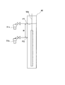
- the vertical autoclave 50 used in the experiment was a cylindrical pressure vessel, and as shown in FIG. 2, the liquid was allowed to escape from a total of two places at a predetermined height from the bottom. Further, a stirrer 50 a is installed inside the autoclave 50. The autoclave 50 is erected so that the longitudinal direction thereof coincides with the vertical direction.
- the prepared slurry was put into the autoclave 50. And extraction of a solvent soluble component was performed for 20 minutes at 400 degreeC. Thereafter, the temperature was lowered to 350 ° C. and stirring was performed, and the liquid level was adjusted by extracting the liquid from the sampling position P1 to the sampling container 51a. Liquid level adjustment means that the liquid level in the autoclave 50 at this time is adjusted so that the liquid level comes to the level (height) of the sampling position P1, as shown in FIG. is there. Further, the concentration C 0 (initial concentration) of the solvent-insoluble component contained in the liquid at this time was measured.
- the liquid was collected into a sampling vessel 51b from the sampling position P2 after a time t, to measure the concentration C t of the solvent-insoluble component contained in the liquid.
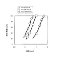
- the sedimentation rate [m / h] of the solvent insoluble component was calculated from the distance H between the sampling position P1 and the sampling position P2 (the distance at which the solvent insoluble component settled) and the standing time t. Further, the sedimentation rate [%] of the solvent-insoluble component was calculated from the initial concentration C 0 and the concentration C t after the standing time t. The results are shown in FIG.
- Example Coal 1 Even in Example Coal 1, a sufficient sedimentation rate was obtained. In Examples Coal 2 and 3, sedimentation was further rapid. Moreover, there was no big difference in the sedimentation speed between Example Coal 2 and Example Coal 3. That is, it is understood that it is preferable to pulverize coal so that the maximum particle size is 1 mm or less in consideration of the cost required for pulverizing coal.
- coal particles having a particle size of 3 mm or less are 90% by weight or more, coal components insoluble in the solvent can be sufficiently separated in the separation step.
- the coal particle size is adjusted so that the coal particle having a particle size of 1 mm or less is 90% by weight or more and the maximum particle size is 3 mm or less, or the maximum particle size is 1 mm or less (all coals If the particle size of the coal is adjusted so that the particle size of the particles is 1 mm or less, coal components insoluble in the solvent can be separated more quickly.
- the separation step of separating the solution containing a coal component that is soluble in the solvent and the solid content concentrate in which the coal component insoluble in the solvent is concentrated methods such as gravity sedimentation, filtration, and centrifugation are used. Can be used.
- the gravity sedimentation method can suppress the equipment cost and operation cost required to implement the method lower than the filtration method and the centrifugal separation method. That is, if the gravity sedimentation method is used in the separation step, ashless coal can be produced at a lower cost.
- the gravity sedimentation method the aggregation state of the solvent-insoluble component is easily maintained, so that the separation efficiency in the separation step is further improved.
- the method for producing ashless coal according to the present embodiment includes a raw material analysis stage, a pulverization process, a raw material separation process, an extraction process, a separation process (a solvent-soluble component separation process), an ashless coal acquisition process, and a by-product coal acquisition process. Have.
- the raw material analysis stage and each process will be described.
- Bituminous coal with a high extraction rate ratio of the soluble component of the coal extracted to a solvent
- cheaper inferior quality coal sublimation
- the raw material analysis stage is a stage in which sedimentation analysis of coal components insoluble in solvents (solvent insoluble components in coal, for example, ash content of coal) is performed for each coal particle size. In addition, sedimentation analysis is performed after pulverizing coal as needed.
- the raw material analysis stage is a stage in which basic data on the relationship between the sedimentation property of coal components insoluble in the solvent and the coal particle size is obtained in advance for the raw material (coal).
- the data shown in FIG. 6 shown later is an example of basic data.
- the particle size (size range) of coal with good sedimentation of coal components insoluble in the solvent, separated in the subsequent raw material separation step and used in the extraction step decide.
- the present inventors found that the sedimentation property of the coal component insoluble in the solvent It was found that the fine particle size tends to be good, but the sedimentation property is worsened when the particle size is extremely fine. Generally, the fineness (smallness) of the particle size becomes higher as the particle cohesiveness. When the cohesion is high, the sedimentation property of the particles in the liquid is improved, that is, the sedimentation rate is increased. This is because the particles strongly aggregate to form a lump and the diameter increases. On the other hand, regarding coal, if the particle size is extremely fine, aggregation of coal components insoluble in the solvent does not proceed sufficiently (low aggregation), and sedimentation may be worsened.
- the sedimentation analysis described above performed in the raw material analysis stage investigates a certain threshold value (particle size threshold value) at which the sedimentation property deteriorates, and coal having a particle size less than this threshold value is less soluble in the solvent than 100% by weight coal. This is to determine a coal particle size range (for example, coal having a particle size equal to or greater than a certain threshold) with good sedimentation of coal components.
- this raw material analysis stage is a series of continuous processes performed every time. There is no need to be done as.
- the raw material analysis step may be performed at least once when the same raw material (coal) is continuously used in the production of ashless coal.
- the particle size of the coal may be set as appropriate according to the particle size distribution of the entire raw material coal, or the analysis may be repeated a plurality of times by changing the particle size range.
- coal Before performing the raw material separation step described later, coal (raw material) is pulverized (pulverization step). From the coal pulverized in this pulverization step, coal having a particle size of a certain threshold or more is separated in the next raw material separation step.
- the coal In the pulverization step, when coal is slurried in a slurry preparation step described later, the coal is pulverized to such an extent that its handling properties (liquidity from the pump, reduction of clogging frequency) are improved. That is, by carrying out the pulverization step, the handling property when coal is slurried is improved.
- the coal is pulverized by a pulverizer (not shown) such that the maximum particle size is about 1 mm to 5 mm.
- coal having a particle size of about 1 mm to 5 mm or less is not 100% by weight. Of course, there are many coals having a particle size of less than 1 mm.
- This pulverization step is not an essential step. For example, even if the collected coal (raw material) is used as it is, if the coal is slurried in a slurry preparation step described later, the pulverization step may be omitted as long as there is no problem in handling properties.
- coal having a particle size equal to or larger than a certain threshold is separated as coal having a predetermined particle size (raw material separation step). Specifically, for example, coal is separated so that coal having a particle size of a certain threshold value or more becomes 95% by weight or more.
- the “coal having a particle size equal to or greater than a certain threshold value” refers to coal having a particle size range determined based on the basic data (analysis result data) obtained in the raw material analysis stage. Further, from the viewpoint of improving the extraction rate, those having a fine particle size show a tendency for the extraction rate to decrease, so that an effect of improving the yield can also be obtained by separation.
- the “certain threshold” (the lower limit value of the particle size of the raw coal) is, for example, 0.075 mm or 0.15 mm. From the viewpoint of improving the extraction rate of coal components soluble in the solvent in the extraction step described later, the threshold is preferably set to 0.075 mm.
- the upper limit of the particle size of the raw coal is, for example, 0.15 mm or 0.25 mm when the lower limit is 0.075 mm. When the lower limit is set to 0.15 mm, the upper limit is set to 0.25 mm, for example.
- the coal of the particle size which is more than a certain threshold value and below a certain upper limit value will be 90 weight% or more regardless of what a lower limit value is made.
- the certain upper limit value is, for example, 0.5 mm, and can be about 5.0 mm.
- a sieve (not shown) is used for separating coal.
- the sieve is installed on the upstream side of the coal hopper 1.
- coal having a particle size less than a certain threshold (coal having a particle size not used for producing ashless coal) is removed by sieving.
- the coal of the particle size more than a certain threshold value used for manufacture of ashless coal is thrown into the coal hopper 1.
- the installation position of the sieve is not limited to the upstream side of the coal hopper 1.
- separation means other than sieving include a screen.
- a sedimentation separation method used as a coal preparation method may be used. This sedimentation separation method can be used because the range of the particle diameter can be limited by the sedimentation range (a small range of particles and a large range of particles can be removed simultaneously).
- a separation method using centrifugal force such as a cyclone can be used.
- Coal with a particle size above a certain threshold may be all coals with a particle size above a certain threshold, or a specific range of particle sizes above a certain threshold (a particle size range with an upper limit as well as a certain threshold (lower limit)). Can be coal.
- the extraction step is a step of heating a slurry obtained by mixing coal and a solvent to extract coal components soluble in the solvent.
- coal having a particle size of a certain threshold value or more separated in the raw material separation step as a coal of a predetermined particle size (specifically, for example, 95% by weight or more of coal having a particle size of a certain threshold value or more is included)
- This extraction step is performed (using coal).
- the extraction process is divided into a slurry preparation process and an extraction main process (solvent-soluble component extraction process).
- the slurry preparation step is performed in the slurry preparation tank 3 in FIG. This extraction process is performed in the preheater 5 and the extraction tank 6 in FIG.
- coal in the slurry is agglomerated by colliding with each other in the extraction tank 6. Since the number of solids in the extraction tank 6 increases as the particle size of the coal decreases, the chance of collision in the extraction main process increases. That is, the smaller the coal particle size, the higher the cohesion. However, as described above, if the particle size of the coal is extremely fine, aggregation of the coal component insoluble in the solvent does not proceed sufficiently (low aggregation property), and the sedimentation property may worsen on the contrary. .
- the separation step (solvent soluble component separation step), as described above, the slurry obtained in the extraction step is subjected to, for example, a gravity sedimentation method, a solution containing coal components soluble in the solvent, and a coal component insoluble in the solvent. Is a step of separating into a concentrated solid content concentrate (solvent insoluble component concentrate). This separation step is performed in the gravity settling tank 7 in FIG.
- the ashless coal acquisition step is a step of obtaining ashless coal (HPC) by evaporating and separating the solvent from the solution (supernatant liquid) separated in the separation step.
- This ashless charcoal acquisition process is performed by the solvent separator 9 in FIG.
- ashless coal can be used as, for example, blended coal of coke raw material or gas turbine direct injection fuel of a high efficiency combined power generation system by gas turbine combustion.
- ashless charcoal can be used as an electrode material for, for example, an electric furnace for steel making and a capacitor.
- the production amount of ashless coal may be smaller than when producing as an application for coke raw materials (while the unit price of ashless coal is higher).
- the production facility may be small. If the production equipment is small (the raw material is small) and the unit price of the product ashless coal is high, the cost of finely pulverizing the raw material (coal) does not significantly affect the total cost of the product (ashless coal) production .
- the by-product coal acquisition step is a step of obtaining by-product coal by evaporating and separating the solvent from the solid content concentrate separated in the separation step.
- This byproduct charcoal acquisition step is performed by the solvent separator 10 in FIG.
- Coal having a particle size of about several centimeters to several tens of centimeters was pulverized to obtain coal having a particle size of 1.0 mm or less (maximum particle size of 1.0 mm or less).
- the particle size distribution of this coal is shown in FIG. In FIG. 5, coal pulverized so as to have a particle size of 1.0 mm or less was classified using sieves having openings of 0.045, 0.075, 0.15, 0.25, and 0.50 mm. The results are graphed.
- the particle size (particle size) distribution was examined by a sieving operation shown in JIS A 1102.
- coals pulverized to have a particle size of 1.0 mm or less a total of three types of coal with particle size ranges of ⁇ 0.075 mm, 0.075-0.150 mm, 0.150-0.250 mm are used. Used in experiments. Note that ⁇ 0.075 mm coal is coal that has passed through a 0.075 mm sieve (coal having a particle size of less than 0.075 mm), and 0.075-0.150 mm coal is 0.150 mm.
- Coal that passed through the sieve but not passed through the sieve of 0.075 mm (coal having a particle size of 0.075 mm or more and less than 0.150 mm), and 0.150-0.250 mm coal is 0.250 mm Coal that passed through the sieve but did not pass through the sieve of 0.150 mm (coal having a particle size of 0.150 mm or more and less than 0.250 mm).
- coal were each mixed with a solvent to prepare a slurry having a coal concentration of 20 wt% dry (based on dry coal).
- a solvent an oil component (coal derivative) purified from coal containing methylnaphthalene, which is a bicyclic aromatic compound, as a main component was used.
- the prepared slurry was put into an autoclave 50 shown in FIG. And extraction of a solvent soluble component was performed for 20 minutes at 400 degreeC. Thereafter, the temperature was lowered to 380 ° C. and stirring was performed, and the liquid level was adjusted by extracting the liquid from the sampling position P1 to the sampling container 51a.
- Liquid level adjustment means that the liquid level in the autoclave 50 at this time is adjusted so that the liquid level comes to the level (height) of the sampling position P1, as shown in FIG. is there. Further, the concentration C 0 (initial concentration) of the solvent-insoluble component contained in the liquid at this time was measured.
- the sedimentation property of the solvent-insoluble component can be maximized by using coal having a particle size larger than a certain threshold.
- This “certain threshold” is, for example, 0.075 mm or 0.15 mm based on the experimental result.
- the extraction step is performed using coal having a particle size equal to or greater than “a certain threshold value” to improve the cohesiveness of the coal component insoluble in the solvent.
- a certain threshold value the separation efficiency of the coal component in the separation step (solvent soluble component separation step) (the sedimentation speed when using the gravity sedimentation method) is improved.
- ashless coal from which ash is sufficiently removed can be produced with high efficiency and at low cost.
- the use of the caking coal described in Patent Document 1 is unnecessary.
- ashless coal for example, even when ashless coal is produced in a coal production area where there is no room for selecting various types of raw material (coal), nothing like caking coal is used.
- ashless coal from which ash is sufficiently removed can be produced at high efficiency and at low cost.
- the extraction rate of a coal component soluble in a solvent increases. According to the present invention, ashless coal can be produced with high efficiency from the viewpoint of increasing the extraction rate of coal components soluble in a solvent.
- the load in the separation step can be reduced as compared with the case where the extraction step is performed using all the raw material coal without going through the raw material separation step.
- a gravity sedimentation tank is used in the separation step, the capacity and the like can be reduced.
- the throughput can be increased in a gravity sedimentation tank of the same scale.
- the “certain threshold (lower limit)” is, for example, 0.075 mm in particle size, as can be seen from FIG. 6, the separation efficiency of coal components insoluble in the solvent is further increased. Moreover, when the particle size of coal (raw material) is extremely fine, the extraction rate of coal components soluble in the solvent tends to decrease. Therefore, by setting the “certain threshold” to, for example, 0.075 mm in particle size, there is an effect that the extraction rate of coal components soluble in the solvent is increased.
- the coal used in the extraction step is not less than “a certain threshold value” and includes 90% by weight or more of coal having a particle size of a certain upper limit value (for example, 5 mm) or less. Extracted using coal separated in the raw material separation step and containing 90% by weight or more of coal having a particle size not less than “a certain threshold value” and not more than a certain upper limit value (for example, 5 mm, particularly preferably 0.5 mm). By performing the process, the separation efficiency due to the improved cohesiveness is further increased.
- a certain threshold value includes 90% by weight or more of coal having a particle size of a certain upper limit value (for example, 5 mm) or less. Extracted using coal separated in the raw material separation step and containing 90% by weight or more of coal having a particle size not less than “a certain threshold value” and not more than a certain upper limit value (for example, 5 mm, particularly preferably 0.5 mm).
- it further has a raw material analysis stage that performs sedimentation analysis of coal components insoluble in the solvent according to the coal particle size, and based on the analysis result of this raw material analysis stage, the separation of the coal used in the extraction process is separated. It is also preferred to determine the particle size. This is because the separation efficiency of the coal component insoluble in the solvent can be reliably improved by performing the sedimentation analysis.
- separation methods such as gravity sedimentation, filtration, and centrifugation are used.
- the gravity sedimentation method can suppress the equipment cost and operation cost necessary for carrying out the method lower than the filtration method and the centrifugal separation method. That is, if the gravity sedimentation method is used in the separation step, ashless coal can be produced at a lower cost.
- the gravity sedimentation method the aggregation state of the solvent-insoluble component is easily maintained, so that the separation efficiency in the separation step is further improved.
- Coal hopper 2 Solvent tank 3: Slurry preparation tank 4: Transfer pump 5: Preheater 6: Extraction tank 7: Gravity settling tank 8: Filter unit 9, 10: Solvent separator 100: Ashless coal production equipment
Landscapes
- Chemical & Material Sciences (AREA)
- Life Sciences & Earth Sciences (AREA)
- Environmental & Geological Engineering (AREA)
- General Life Sciences & Earth Sciences (AREA)
- Geochemistry & Mineralogy (AREA)
- Geology (AREA)
- Oil, Petroleum & Natural Gas (AREA)
- Organic Chemistry (AREA)
- Engineering & Computer Science (AREA)
- Combustion & Propulsion (AREA)
- Solid Fuels And Fuel-Associated Substances (AREA)
Description
図1に示すように、無灰炭製造設備100は、無灰炭(HPC)製造工程の上流側から順に、石炭ホッパ1・溶剤タンク2、スラリー調製槽3、移送ポンプ4、予熱器5、抽出槽6、重力沈降槽7、フィルターユニット8、および溶剤分離器9・10を備えている。
原料である石炭と溶剤とを混合する、後述するスラリー調製工程を行う前に、先ず、石炭の粒度が所定の粒度となるように、石炭の粒度の調整を行う(粒度調整工程)。これにより、溶剤に不溶な石炭成分(溶剤不溶成分、例えば灰分)の凝集性を向上させる。
より好適には、粒径が1mm以下の石炭粒子が90重量%以上、かつ最大粒径が3mm以下となるように石炭の粒度の調整を行う。
さらに好適には、最大粒径が、1mm以下、最も好ましくは0.5mm以下となるように、すなわち、全ての石炭粒子の粒径が1mm以下、最も好ましくは0.5mm以下となるように、石炭の粒度の調整を行うと良い。
抽出工程は、石炭と溶剤とを混合して得られるスラリーを加熱して溶剤に可溶な石炭成分を抽出する工程である。この抽出工程は、例えば粉砕により所定の粒度に粒度調整がなされた石炭と溶剤とを混合してスラリーを調製するスラリー調製工程と、スラリー調製工程で得られたスラリーを加熱して溶剤に可溶な石炭成分を抽出する抽出本工程(溶剤可溶成分抽出工程)とに分かれている。
スラリー調製工程は、石炭と溶剤とを混合してスラリーを調製する工程である。このスラリー調製工程は、図1中、スラリー調製槽3で実施される。原料である石炭が石炭ホッパ1からスラリー調製槽3に投入されるとともに、溶剤タンク2からスラリー調製槽3に溶剤が投入される。スラリー調製槽3に投入された石炭および溶剤は、攪拌機3aで混合されて石炭と溶剤とからなるスラリーとなる。
抽出本工程は、スラリー調製工程で得られたスラリーを加熱して溶剤に可溶な石炭成分を抽出する(溶剤に溶解させる)工程である。この抽出本工程は、図1中、予熱器5および抽出槽6で実施される。スラリー調製槽3にて調製されたスラリーは、移送ポンプ4によって、予熱器5に供給されて所定温度まで加熱された後、抽出槽6に供給され、攪拌機6aで攪拌されながら所定温度で保持されて抽出が行われる。
分離工程は、抽出工程で得られたスラリーを、例えば重力沈降法により、溶剤に可溶な石炭成分を含む溶液と、溶剤に不溶な石炭成分が濃縮した固形分濃縮液(溶剤不溶成分濃縮液)とに分離する工程である。この分離工程は、図1中、重力沈降槽7で実施される。抽出工程で得られたスラリーは、重力沈降槽7内で、重力にて、溶液としての上澄み液と、固形分濃縮液とに分離される。重力沈降槽7の上部の上澄み液は、必要に応じてフィルターユニット8を経て、溶剤分離器9へ送られる。重力沈降槽7の下部に沈降した固形分濃縮液は溶剤分離器10へ送られる。
無灰炭取得工程は、分離工程で分離された溶液(上澄み液)から溶剤を蒸発分離して無灰炭(HPC)を得る工程である。この無灰炭取得工程は、図1中、溶剤分離器9で実施される。重力沈降槽7で分離された溶液は、フィルターユニット8で濾過された後、溶剤分離器9に供給され、溶剤分離器9内で上澄み液から溶剤が蒸発分離される。
副生炭取得工程は、分離工程で分離された固形分濃縮液から溶剤を蒸発分離して副生炭を得る工程である。この副生炭取得工程は、図1中、溶剤分離器10で実施される。重力沈降槽7で分離された固形分濃縮液は溶剤分離器10に供給され、溶剤分離器10内で固形分濃縮液から溶剤が蒸発分離される。なお、副生炭取得工程は、必須の工程ではない。
本発明に係る製造方法により溶剤に不溶な石炭成分(例えば灰分)の沈降性(分離性、沈降速度)が向上することを検証した。図2~図4を参照しつつ説明する。
本発明では、石炭と溶剤とを混合する前に石炭の粒度の調整を行うことで、溶剤に不溶な石炭成分の凝集性を向上させる。溶剤に不溶な石炭成分の凝集性が向上することで、分離工程における当該石炭成分の分離効率(重力沈降法を用いた場合には沈降速度)が向上する。その結果、灰分が十分に除去された無灰炭を高効率で製造することができる。この製造方法では、特許文献1に記載の粘結炭のようなものの使用は不要である。すなわち、本発明によれば、例えば原料(石炭)の炭種を種々選択できる余地がない石炭の産地で無灰炭を製造する場合であっても、灰分が十分に除去された無灰炭を高効率、かつ安価に製造することができる。
次に、図1、図2、図5、図6を参照しつつ、第2実施形態に係る無灰炭の製造方法について説明する。本実施形態の無灰炭の製造方法は、原料分析段階、粉砕工程、原料分離工程、抽出工程、分離工程(溶剤可溶成分分離工程)、無灰炭取得工程、および副生炭取得工程を有する。以下、原料分析段階および各工程について説明する。なお、本製造方法において原料とする石炭に、特に制限はなく、抽出率(溶剤に抽出される石炭の可溶成分の割合)の高い瀝青炭を用いてもよいし、より安価な劣質炭(亜瀝青炭、褐炭)を用いてもよい。
原料分析段階は、溶剤に不溶な石炭成分(石炭中の溶剤不溶成分、例えば石炭の灰分)の沈降性分析を石炭の粒度別に行う段階である。なお、必要に応じて、石炭を粉砕した上で沈降性分析を行う。
一般的に粒子の凝集性は、その粒度が細かい(小さい)方が高くなる。凝集性が高いと、液体中における粒子の沈降性がよくなる、すなわち沈降速度が大きくなる。粒子同士が強く凝集して塊となり、その径が大きくなるからである。一方で、石炭に関しては、その粒子径が極端に微細であると、溶剤に不溶な石炭成分の凝集が十分に進行せず(凝集性が低く)、沈降性が反対に悪化することがある。
後述する原料分離工程を行う前に、石炭(原料)の粉砕を行う(粉砕工程)。この粉砕工程で粉砕された石炭から、この次の原料分離工程にて、ある閾値以上の粒度の石炭を分離する。粉砕工程では、後述するスラリー調製工程にて石炭をスラリー化した際に、そのハンドリング性(ポンプからの送液性,閉塞発生頻度の低減)が良好となる程度まで石炭の粉砕を行う。すなわち、当該粉砕工程を実施することで、石炭をスラリー化した際のハンドリング性が向上する。具体的には、粉砕機(不図示)により、例えば最大粒子径が1mm~5mm程度の粒径になるように石炭を粉砕する。なお、最大粒子径が1mm~5mm程度の粒径になるように石炭を粉砕するといっても、1mm~5mm程度の粒径以下の石炭が100重量%になるというものではない。もちろん粒径が1mm未満の石炭も多く存在する。なお、この粉砕工程は必須の工程ではない。例えば、採取した石炭(原料)をそのまま用いても、後述するスラリー調製工程にて石炭をスラリー化した際に、そのハンドリング性において支障がないものであれば、粉砕工程を省略してもよい。
原料である石炭と溶剤とを混合する、後述するスラリー調製工程を行う前に、先ず、ある閾値以上の粒度の石炭を所定の粒度の石炭として分離する(原料分離工程)。具体的には、例えば、ある閾値以上の粒度の石炭が95重量%以上になるように石炭を分離する。なお、「ある閾値以上の粒度の石炭」とは、前記した原料分析段階で得られた基礎データ(分析結果データ)に基づいて決定された粒度範囲の石炭のことである。また、抽出率向上の観点からも微細な粒子径を有するものは抽出率が低下傾向を示すことから、分離することで収率の向上効果も得られる。
ある閾値以上の粒度の石炭とは、ある閾値以上の粒度の石炭全てである場合もあるし、ある閾値以上の特定範囲の粒度(ある閾値(下限値)だけでなく上限値もある粒度範囲)の石炭である場合もある。
抽出工程は、上述したように、石炭と溶剤とを混合して得られるスラリーを加熱して溶剤に可溶な石炭成分を抽出する工程である。前記した原料分離工程で分離された、ある閾値以上の粒度の石炭を所定の粒度の石炭として用いて(具体的には、例えば、ある閾値以上の粒度の石炭が95重量%以上含まれている石炭を用いて)この抽出工程を行う。抽出工程は、上述したように、スラリー調製工程と抽出本工程(溶剤可溶成分抽出工程)とに分かれている。スラリー調製工程は、図1中、スラリー調製槽3で実施される。抽出本工程は、図1中、予熱器5および抽出槽6で実施される。
分離工程(溶剤可溶成分分離工程)は、上述したように、抽出工程で得られたスラリーを、例えば重力沈降法により、溶剤に可溶な石炭成分を含む溶液と、溶剤に不溶な石炭成分が濃縮した固形分濃縮液(溶剤不溶成分濃縮液)とに分離する工程である。この分離工程は、図1中、重力沈降槽7で実施される。
無灰炭取得工程は、上述したように、分離工程で分離された溶液(上澄み液)から溶剤を蒸発分離して無灰炭(HPC)を得る工程である。この無灰炭取得工程は、図1中、溶剤分離器9で実施される。
副生炭取得工程は、上述したように、分離工程で分離された固形分濃縮液から溶剤を蒸発分離して副生炭を得る工程である。この副生炭取得工程は、図1中、溶剤分離器10で実施される。
本発明に係る製造方法により溶剤に不溶な石炭成分(例えば灰分)の沈降性(分離性、沈降速度)が向上することを検証した。図2、図5、図6を適宜参照しつつ説明する。
なお、<0.075mmの石炭とは、0.075mmの篩いを通過した石炭(粒径が0.075mm未満の石炭)であり、0.075-0.150mmの石炭とは、0.150mmの篩いを通過したが0.075mmの篩いは通過しなかった石炭(粒径が0.075mm以上0.150mm未満の石炭)であり、0.150-0.250mmの石炭とは、0.250mmの篩いを通過したが0.150mmの篩いは通過しなかった石炭(粒径が0.150mm以上0.250mm未満の石炭)である。
本発明では、「ある閾値」以上の粒度の石炭を用いて抽出工程を行い、溶剤に不溶な石炭成分の凝集性を向上させる。溶剤に不溶な石炭成分の凝集性が向上することで、分離工程(溶剤可溶成分分離工程)における当該石炭成分の分離効率(重力沈降法を用いた場合には沈降速度)が向上する。その結果、灰分が十分に除去された無灰炭を高効率、かつ安価に製造することができる。この製造方法では、特許文献1に記載の粘結炭のようなものの使用は不要である。すなわち、本発明によれば、例えば原料(石炭)の炭種を種々選択できる余地がない石炭の産地で無灰炭を製造する場合であっても、粘結炭のようなものをいっさい用いずに灰分が十分に除去された無灰炭を高効率、かつ安価に製造することができる。また、ある閾値以上の粒度の石炭を用いて抽出工程を行うことで、溶剤に不溶な石炭成分の凝集性が向上することに加えて、溶剤に可溶な石炭成分の抽出率が高まる。本発明によれば、溶剤に可溶な石炭成分の抽出率が高まるという観点からも、無灰炭を高効率で製造することができる。
2:溶剤タンク
3:スラリー調製槽
4:移送ポンプ
5:予熱器
6:抽出槽
7:重力沈降槽
8:フィルターユニット
9、10:溶剤分離器
100:無灰炭製造設備
Claims (12)
- 石炭と溶剤とを混合して得られるスラリーを加熱して溶剤に可溶な石炭成分を抽出する抽出工程と、
前記抽出工程で得られたスラリーを、溶剤に可溶な石炭成分を含む溶液と、溶剤に不溶な石炭成分が濃縮した固形分濃縮液とに分離する分離工程と、
前記分離工程で分離された溶液から溶剤を蒸発分離して無灰炭を得る無灰炭取得工程と、
を備える、無灰炭の製造方法において、
所定の粒度の石炭を用いて前記抽出工程を行うことで、溶剤に不溶な石炭成分の凝集性を向上させることを特徴とする、無灰炭の製造方法。 - 請求項1に記載の無灰炭の製造方法において、
石炭と溶剤とを混合する前に石炭の粒度の調整を行う粒度調整工程をさらに備え、
前記粒度調整工程で、前記所定の粒度となるように石炭の粒度の調整を行うことを特徴とする、無灰炭の製造方法。 - 請求項2に記載の無灰炭の製造方法において、
前記粒度調整工程で、粒径が3mm以下の石炭粒子が90重量%以上となるように石炭の粒度の調整を行うことを特徴とする、無灰炭の製造方法。 - 請求項3に記載の無灰炭の製造方法において、
前記粒度調整工程で、粒径が1mm以下の石炭粒子が90重量%以上、かつ最大粒径が3mm以下となるように石炭の粒度の調整を行うことを特徴とする、無灰炭の製造方法。 - 請求項4に記載の無灰炭の製造方法において、
前記粒度調整工程で、最大粒径が1mm以下となるように石炭の粒度の調整を行うことを特徴とする、無灰炭の製造方法。 - 請求項2または3に記載の無灰炭の製造方法において、
前記粒度調整工程で、石炭を粉砕することによりその粒度の調整を行うことを特徴とする、無灰炭の製造方法。 - 請求項2または3に記載の無灰炭の製造方法において、
前記分離工程において重力沈降法を用いることを特徴とする、無灰炭の製造方法。 - 請求項1に記載の無灰炭の製造方法において、
石炭と溶剤とを混合する前に、ある閾値以上の粒度の石炭を分離する原料分離工程をさらに備え、
前記原料分離工程で分離された、前記ある閾値以上の粒度の石炭を前記所定の粒度の石炭として用いて前記抽出工程を行うことを特徴とする、無灰炭の製造方法。 - 請求項8に記載の無灰炭の製造方法において、
前記ある閾値以上の粒度の石炭が95重量%以上になるように分離した石炭を用いて前記抽出工程を行うことを特徴とする、無灰炭の製造方法。 - 請求項8または9に記載の無灰炭の製造方法において、
前記原料分離工程において、前記ある閾値以上であって、ある上限値以下の粒度の石炭が90重量%以上となるように石炭を分離し、
前記原料分離工程で分離された、前記ある閾値以上であって、ある上限値以下の粒度の石炭が90重量%以上含まれている石炭を用いて前記抽出工程を行うことを特徴とする、無灰炭の製造方法。 - 請求項8または9に記載の無灰炭の製造方法において、
溶剤に不溶な石炭成分の沈降性分析を石炭の粒度別に行う原料分析段階を有し、
前記原料分析段階の分析結果に基づいて、前記原料分離工程で分離して前記抽出工程で用いる石炭の粒度を決定することを特徴とする、無灰炭の製造方法。 - 請求項8または9に記載の無灰炭の製造方法において、
前記原料分離工程より前に、石炭の粉砕を行う粉砕工程を有し、
前記原料分離工程において、前記粉砕工程で粉砕された石炭から、前記ある閾値以上の粒度の石炭を分離することを特徴とする、無灰炭の製造方法。
Priority Applications (3)
| Application Number | Priority Date | Filing Date | Title |
|---|---|---|---|
| AU2013321344A AU2013321344B2 (en) | 2012-09-26 | 2013-09-19 | Method for manufacturing ashless coal |
| CN201380049959.8A CN104685037B (zh) | 2012-09-26 | 2013-09-19 | 无灰煤的制造方法 |
| KR1020157007258A KR101747564B1 (ko) | 2012-09-26 | 2013-09-19 | 무회탄의 제조 방법 |
Applications Claiming Priority (4)
| Application Number | Priority Date | Filing Date | Title |
|---|---|---|---|
| JP2012212268A JP2014065823A (ja) | 2012-09-26 | 2012-09-26 | 無灰炭の製造方法 |
| JP2012-212268 | 2012-09-26 | ||
| JP2012226560A JP6199020B2 (ja) | 2012-10-12 | 2012-10-12 | 無灰炭の製造方法 |
| JP2012-226560 | 2012-10-12 |
Publications (1)
| Publication Number | Publication Date |
|---|---|
| WO2014050706A1 true WO2014050706A1 (ja) | 2014-04-03 |
Family
ID=50388111
Family Applications (1)
| Application Number | Title | Priority Date | Filing Date |
|---|---|---|---|
| PCT/JP2013/075359 Ceased WO2014050706A1 (ja) | 2012-09-26 | 2013-09-19 | 無灰炭の製造方法 |
Country Status (4)
| Country | Link |
|---|---|
| KR (1) | KR101747564B1 (ja) |
| CN (1) | CN104685037B (ja) |
| AU (1) | AU2013321344B2 (ja) |
| WO (1) | WO2014050706A1 (ja) |
Citations (3)
| Publication number | Priority date | Publication date | Assignee | Title |
|---|---|---|---|---|
| JP2011001240A (ja) * | 2009-06-22 | 2011-01-06 | Kobe Steel Ltd | 炭素材料の製造方法 |
| JP2012031238A (ja) * | 2010-07-28 | 2012-02-16 | Kobe Steel Ltd | 無灰炭の製造方法 |
| WO2012118151A1 (ja) * | 2011-03-03 | 2012-09-07 | 株式会社神戸製鋼所 | 炭素材料の製造方法 |
Family Cites Families (5)
| Publication number | Priority date | Publication date | Assignee | Title |
|---|---|---|---|---|
| DE10393609B4 (de) * | 2002-10-29 | 2020-08-06 | Ucc Energy Pty Ltd. | Verfahren zur Entmineralisierung von Kohle |
| JP4045232B2 (ja) * | 2003-11-07 | 2008-02-13 | 株式会社神戸製鋼所 | 低品位炭を原料とする固形燃料の製造方法および製造装置 |
| KR101070673B1 (ko) * | 2009-04-10 | 2011-10-07 | 주식회사 동양탄소 | 무연탄의 저회분화 방법 및 이에 의해 제조된 무연탄을 사용한 활성탄소 제조방법 |
| CN102512846A (zh) * | 2011-11-22 | 2012-06-27 | 河北钢铁集团有限公司 | 一种热萃取煤的方法 |
| KR101317772B1 (ko) | 2012-09-20 | 2013-10-15 | 한국에너지기술연구원 | 저등급 석탄의 개질방법 |
-
2013
- 2013-09-19 WO PCT/JP2013/075359 patent/WO2014050706A1/ja not_active Ceased
- 2013-09-19 CN CN201380049959.8A patent/CN104685037B/zh active Active
- 2013-09-19 AU AU2013321344A patent/AU2013321344B2/en not_active Ceased
- 2013-09-19 KR KR1020157007258A patent/KR101747564B1/ko active Active
Patent Citations (3)
| Publication number | Priority date | Publication date | Assignee | Title |
|---|---|---|---|---|
| JP2011001240A (ja) * | 2009-06-22 | 2011-01-06 | Kobe Steel Ltd | 炭素材料の製造方法 |
| JP2012031238A (ja) * | 2010-07-28 | 2012-02-16 | Kobe Steel Ltd | 無灰炭の製造方法 |
| WO2012118151A1 (ja) * | 2011-03-03 | 2012-09-07 | 株式会社神戸製鋼所 | 炭素材料の製造方法 |
Also Published As
| Publication number | Publication date |
|---|---|
| AU2013321344A1 (en) | 2015-04-09 |
| KR20150046250A (ko) | 2015-04-29 |
| KR101747564B1 (ko) | 2017-06-14 |
| AU2013321344B2 (en) | 2016-01-21 |
| CN104685037A (zh) | 2015-06-03 |
| CN104685037B (zh) | 2018-09-11 |
Similar Documents
| Publication | Publication Date | Title |
|---|---|---|
| JP5280072B2 (ja) | コークスの製造方法 | |
| JP5241105B2 (ja) | コークスの製造方法、及び銑鉄の製造方法 | |
| TWI485237B (zh) | Forming blended coal and its manufacturing method, and coke and its manufacturing method | |
| JP4109686B2 (ja) | コークスの製造方法、及び、銑鉄の製造方法 | |
| CN102154049B (zh) | 一种利用低阶无粘结性煤改质制备炼焦煤的方法 | |
| JP5530292B2 (ja) | 製鉄用コークスの製造方法 | |
| JP5128351B2 (ja) | 炭素材料の製造方法 | |
| JP5247193B2 (ja) | コークスの製造方法、及び、銑鉄の製造方法 | |
| JP5636356B2 (ja) | 無灰炭成形物の製造方法 | |
| JP2014065823A (ja) | 無灰炭の製造方法 | |
| JP6199020B2 (ja) | 無灰炭の製造方法 | |
| WO2014050706A1 (ja) | 無灰炭の製造方法 | |
| KR20140009629A (ko) | 저등급 석탄의 개질방법 | |
| JP2014189739A (ja) | 無灰炭の製造装置および無灰炭の製造方法 | |
| JP4950527B2 (ja) | コークスの製造方法、及び、銑鉄の製造方法 | |
| AU2016360026B2 (en) | Method for producing ash-free coal | |
| AU2014258669B2 (en) | Method for producing molded solid fuel | |
| JP5739785B2 (ja) | 残渣炭成形物の製造方法 | |
| JP2014019746A (ja) | 副生炭成形物の製造方法 | |
| JP2014163634A (ja) | 副生炭の燃焼方法 | |
| JP5710459B2 (ja) | 無灰炭の製造方法 | |
| JPS6142593A (ja) | 石炭類の脱金属方法 | |
| JP5719283B2 (ja) | 副生炭成形物の製造方法 | |
| JP2008174623A (ja) | コークスの製造方法、及び、銑鉄の製造方法 | |
| JPS60206895A (ja) | 石炭スラリ−の製造方法 |
Legal Events
| Date | Code | Title | Description |
|---|---|---|---|
| 121 | Ep: the epo has been informed by wipo that ep was designated in this application |
Ref document number: 13841877 Country of ref document: EP Kind code of ref document: A1 |
|
| ENP | Entry into the national phase |
Ref document number: 20157007258 Country of ref document: KR Kind code of ref document: A |
|
| NENP | Non-entry into the national phase |
Ref country code: DE |
|
| WWE | Wipo information: entry into national phase |
Ref document number: IDP00201501757 Country of ref document: ID |
|
| ENP | Entry into the national phase |
Ref document number: 2013321344 Country of ref document: AU Date of ref document: 20130919 Kind code of ref document: A |
|
| 122 | Ep: pct application non-entry in european phase |
Ref document number: 13841877 Country of ref document: EP Kind code of ref document: A1 |