WO2014050670A1 - 加湿装置 - Google Patents
加湿装置 Download PDFInfo
- Publication number
- WO2014050670A1 WO2014050670A1 PCT/JP2013/075219 JP2013075219W WO2014050670A1 WO 2014050670 A1 WO2014050670 A1 WO 2014050670A1 JP 2013075219 W JP2013075219 W JP 2013075219W WO 2014050670 A1 WO2014050670 A1 WO 2014050670A1
- Authority
- WO
- WIPO (PCT)
- Prior art keywords
- filter
- air
- humidifier
- ventilation path
- humidifying
- Prior art date
- Legal status (The legal status is an assumption and is not a legal conclusion. Google has not performed a legal analysis and makes no representation as to the accuracy of the status listed.)
- Ceased
Links
Images



Classifications
-
- F—MECHANICAL ENGINEERING; LIGHTING; HEATING; WEAPONS; BLASTING
- F24—HEATING; RANGES; VENTILATING
- F24F—AIR-CONDITIONING; AIR-HUMIDIFICATION; VENTILATION; USE OF AIR CURRENTS FOR SCREENING
- F24F6/00—Air-humidification, e.g. cooling by humidification
- F24F6/02—Air-humidification, e.g. cooling by humidification by evaporation of water in the air
- F24F6/06—Air-humidification, e.g. cooling by humidification by evaporation of water in the air using moving unheated wet elements
-
- F—MECHANICAL ENGINEERING; LIGHTING; HEATING; WEAPONS; BLASTING
- F24—HEATING; RANGES; VENTILATING
- F24F—AIR-CONDITIONING; AIR-HUMIDIFICATION; VENTILATION; USE OF AIR CURRENTS FOR SCREENING
- F24F13/00—Details common to, or for air-conditioning, air-humidification, ventilation or use of air currents for screening
- F24F13/24—Means for preventing or suppressing noise
-
- F—MECHANICAL ENGINEERING; LIGHTING; HEATING; WEAPONS; BLASTING
- F24—HEATING; RANGES; VENTILATING
- F24F—AIR-CONDITIONING; AIR-HUMIDIFICATION; VENTILATION; USE OF AIR CURRENTS FOR SCREENING
- F24F13/00—Details common to, or for air-conditioning, air-humidification, ventilation or use of air currents for screening
- F24F13/28—Arrangement or mounting of filters
-
- F—MECHANICAL ENGINEERING; LIGHTING; HEATING; WEAPONS; BLASTING
- F24—HEATING; RANGES; VENTILATING
- F24F—AIR-CONDITIONING; AIR-HUMIDIFICATION; VENTILATION; USE OF AIR CURRENTS FOR SCREENING
- F24F6/00—Air-humidification, e.g. cooling by humidification
- F24F2006/008—Air-humidifier with water reservoir
-
- F—MECHANICAL ENGINEERING; LIGHTING; HEATING; WEAPONS; BLASTING
- F24—HEATING; RANGES; VENTILATING
- F24F—AIR-CONDITIONING; AIR-HUMIDIFICATION; VENTILATION; USE OF AIR CURRENTS FOR SCREENING
- F24F13/00—Details common to, or for air-conditioning, air-humidification, ventilation or use of air currents for screening
- F24F13/24—Means for preventing or suppressing noise
- F24F2013/247—Active noise-suppression
Definitions
- the present invention relates to a humidifier that performs humidification by releasing air that has passed through a filter containing water.
- FIG. 1 is a schematic cross-sectional view showing a structural example of a conventional humidifier.
- the filter 74 formed in a circular shape with a water-absorbing material is arranged vertically, and the filter 74 is rotated while being immersed in the water tank 75 so that the filter 74 contains water.
- a motor 73 for rotating the filter 74 is fixed to a member 72 constituting a part of the ventilation path 7. In FIG. 1, the member 72 is shown highlighted in black. During operation, the motor 73 rotates the filter 74 by interlocking with a gear (not shown) meshed with the frame of the filter 74.
- the present invention has been made in view of such circumstances, and an object of the present invention is to provide a humidifying device in which noise is reduced by improving the arrangement of the motor.
- the humidifier according to the present invention has water absorption and air permeability, and has a flat plate filter that is rotated for water absorption, a motor for rotating the filter, and air after passing through the filter.
- the motor is fixed to a fixing member different from a member constituting the ventilation passage. .
- a humidifier including a filter that is rotated for water absorption includes a ventilation path whose end is an air outlet, and air that has passed through the filter is discharged from the outlet through the ventilation path.
- the motor for rotating the filter is fixed to a fixing member that is different from the member constituting the ventilation path. For this reason, the vibration of the motor is not directly transmitted to the members constituting the ventilation path.
- the humidifying device according to the present invention is characterized in that the fixing member is separated from a member constituting the ventilation path.
- the fixing member to which the motor is fixed is separated from the members constituting the ventilation path. For this reason, it is difficult for the vibration of the motor to be indirectly transmitted to the members constituting the ventilation path.
- the humidifier according to the present invention is characterized in that the fixing member is a plate-like member in which a plurality of ventilation holes are formed in part, and is disposed on the windward side of the filter.
- the fixing member to which the motor is fixed is arranged on the windward side of the filter. Water is less likely to enter the motor than when the motor is on the leeward side of the filter.
- the humidifier according to the present invention is characterized in that an air cleaning filter is disposed on the windward side of the fixing member.
- an air cleaning filter is arranged on the windward side of the fixing member to which the motor is fixed. The air sucked through the air cleaning filter is finally discharged from the outlet and the air is cleaned.
- the present invention noise caused by driving the motor for rotating the filter is difficult to propagate through the ventilation path in the humidifier, and noise leaking from the outlet is reduced. Therefore, the present invention has an excellent effect, for example, it is possible to silence the humidifier.
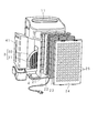
- FIG. 2 is an exploded perspective view of the humidifier
- FIG. 3 is a schematic side sectional view showing a schematic configuration of the humidifier.
- FIG. 3 shows the front as left and the back as right
- FIG. 2 is a perspective view seen from the back side (right side in FIG. 3).
- the front side is the front and the back side is the rear.
- the humidifier includes a blower 6, a humidifying filter unit 3, and a water tank 4 inside a vertically long rectangular box-shaped housing. As shown in FIG. 3, the interior of the housing is divided by a partition member 12 into a rear suction chamber 2 and a front ventilation path 1.
- the suction chamber 2 communicates with the outside through a number of suction ports 25 provided in the rear panel 24 of the housing.
- the ventilation path 1 communicates with the outside through an air outlet 11 provided in the top plate of the housing.
- the terminal end of the ventilation path 1 is a blower outlet 11, and the partition wall member 12 is a member constituting a part of the ventilation path 1.
- the suction chamber 2 and the ventilation path 1 are communicated with each other through a large number of ventilation holes provided in the lower part of the partition wall member 12.
- the rear panel 24 is detachable, and a deodorizing filter 23 and a dust collecting filter 22 are stacked on the front side of the rear panel 24.
- the deodorizing filter 23 is formed by, for example, dispersing and holding activated carbon in a non-woven fabric, and acts to adsorb and remove odorous components during ventilation.
- the dust collection filter 22 is a known HEPA (HighHEfficiency Particulate Air) filter, for example, and functions to collect and remove fine dust contained in the air.
- a plate-like partition member 21 that partitions the suction chamber 2 is disposed on the front side of the dust collection filter 22.
- a large number of ventilation holes are formed in the partition member 21, and air passes therethrough.
- the partition member 21 is fixed in the humidifier.
- the deodorizing filter 23 and the dust collection filter 22 are integrated separately into a rectangular frame made of synthetic resin, and are fitted between the partition member 21 and the rear panel 24.
- the blower 6 includes an impeller 60 and a motor 61 that drives the impeller 60.
- the motor 61 is fixed in the ventilation path 1, and the impeller 60 is connected to the rotation shaft of the motor 61 and is arranged to face a large number of ventilation holes provided in the lower part of the partition wall member 12.
- the impeller 60 is rotated by driving the motor 61, and the blower 6 sucks air from the direction of the rotation axis and sends out the air in the centrifugal direction.
- air flows from the outside into the suction chamber 2 through the suction port 25 of the rear panel 24 as indicated by the white arrow in FIG. 3.
- the air that has flowed in flows forward through the suction chamber 2 through the ventilation holes of the partition member 21, is sucked into the blower 6 through the ventilation holes in the lower part of the partition wall member 12, and changes the direction upward to change the direction of the ventilation path 1. It is led out to the inside and discharged to the outside through the air outlet 11.
- the deodorizing filter 23 and the dust collecting filter 22 are located on the upstream side of the air flow, and the air introduced into the suction chamber 2 through the suction port 25 is removed of odor components by passing through the deodorizing filter 23.
- the dust is removed by passing through the dust collection filter 22.
- the deodorizing filter 23 and the dust collecting filter 22 correspond to the air cleaning filter in the present invention.
- the humidifier also functions as an air cleaner by the deodorizing filter 23 and the dust collection filter 22.
- the humidifying filter unit 3 and the water tank 4 are disposed between the partition member 21 and the blower 6 in order to humidify the air that has flowed into the humidifying device.
- the humidifying filter unit 3 is configured by storing and holding a humidifying filter 31 inside a holding frame 30 having a hollow disk shape.
- the humidifying filter 31 is formed in a flat plate shape by folding a sheet made of a material that has water absorbability such as rayon and can be ventilated into a bellows shape, and is housed inside the holding frame 30.
- the humidification filter 31 corresponds to the filter in the present invention.
- the shape of the humidifying filter 31 housed inside the holding frame 30 is a shape that lacks a part of the disk.
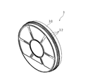
- FIG. 4 is a perspective view of the humidifying filter unit 3. In FIG.
- FIG. 4 the front side of the humidification filter unit 3 is shown with the perspective view.
- the holding frame 30 of the humidifying filter unit 3 is illustrated, and the humidifying filter 31 held by the holding frame 30 is omitted.
- a ring gear portion 32 having an appropriate width in which teeth are formed over the entire circumference in the central portion in the width direction is integrally provided.
- the water tank 4 has a rectangular deep dish shape and is placed on the bottom plate of the housing.
- the upper surface of the water tank 4 is opened, and the humidifying filter unit 3 is disposed on the upper side of the water tank 4.
- the lower part of the humidification filter unit 3 enters from the upper side of the water tank 4 and is located inside the water tank 4.
- the humidifying filter 31 is substantially vertical. Water is supplied to the water tank 4 from the tank 41 so as to keep the water level constant.
- the humidifier is provided with a drive motor 5 for rotationally driving the humidification filter unit 3.
- the drive motor 5 corresponds to the motor in the present invention.
- the drive motor 5 is fixed to the partition member 21 and is disposed above the humidifying filter unit 3.
- the partition member 21 corresponds to the fixing member in the present invention.
- a transmission gear (not shown) is connected to the drive motor 5, and a drive gear (not shown) is engaged with the transmission gear.
- the ring gear portion 32 of the humidifying filter unit 3 is meshed with the drive gear.
- the lower portion of the rotating humidifying filter unit 3 is submerged in the water tank 4, and the peripheral portion of the humidifying filter 31 is intermittently submerged while rotating.
- the water in the water tank 4 is sucked up by the humidifying filter 31 and lifted by the rotation of the humidifying filter unit 3.
- Water absorption is performed from the peripheral portion of the humidifying filter 31 toward the central portion, and the humidifying filter 31 contains water.
- the air flowing through the suction chamber 2 by the operation of the blower 6 passes through the humidifying filter 31 containing water.
- water contained in the humidifying filter 31 is vaporized, and the air becomes air containing the vaporized water.
- the humidifier stops the humidification filter unit 3 at a position where the humidification filter 31 having a shape lacking a part of the disk does not submerge. In this state, the humidification filter 31 does not absorb water, so humidification is stopped.
- FIG. 5 is a schematic side cross-sectional view of the humidifying device with emphasis on the partition member 12 and the partition member 21.
- the partition wall member 12 and the partition member 21 are highlighted in black.
- the drive motor 5 is fixed to the partition member 21 and is not attached to a member constituting the ventilation path 1 such as the partition wall member 12. For this reason, the vibration of the drive motor 5 is not directly transmitted to the members constituting the ventilation path 1.
- the partition member 21 to which the drive motor 5 is fixed is separated from the partition member 12 constituting a part of the ventilation path 1. Since the member to which the drive motor 5 is fixed is separated from the member constituting the ventilation path 1, the vibration of the drive motor 5 is not easily transmitted to the member constituting the ventilation path 1. Since the vibration of the drive motor 5 is not easily transmitted to the members constituting the ventilation path 1, the noise caused by driving is difficult to propagate through the ventilation path 1, and the noise leaking from the air outlet 11 is reduced.
- the drive motor 5 is fixed to the partition member 21 on the windward side of the humidifying filter unit 3.
- the drive motor since the drive motor is disposed on the leeward side of the humidification filter unit, there is a possibility that water transmitted through the holding frame or scattered water enters the drive motor along the air flow.
- the drive motor 5 since the drive motor 5 is arranged on the windward side compared to the conventional case, it is difficult for water to enter the drive motor 5 as compared with the conventional case, and deterioration of the drive motor 5 is suppressed.
- the internal configuration of the humidifier shown in FIGS. 3 and 5 is an example, and the humidifier may have other configurations.
- the drive motor 5 may be fixed to a member other than the partition member 21 as long as the drive motor 5 is fixed to a member different from the members constituting the ventilation path 1.
- the drive motor 5 may be fixed to a member that is in contact with a member constituting the ventilation path 1.
- the effect of reducing the noise is slightly reduced as compared with the embodiment in which the drive motor 5 is fixed to a member separated from the member constituting the ventilation path 1, but the drive motor is included in the member constituting the conventional ventilation path.
- the ventilation path 1 may be comprised by the combination of more members than the structure shown in FIG.3 and FIG.5.
- the air blower 6 may be arrange
- the mode in which the humidifying filter 31 is rotated using the ring gear portion 32 provided on the outer peripheral surface of the holding frame 30 has been shown.
- the humidifier is provided coaxially on one surface of the holding frame 30.
- annular gear part formed may be sufficient.
- the humidification apparatus may be the form which absorbs water, without being immersed in a humidification filter.
- the form provided with the mechanism which supplies water to the humidification filter which rotates may be sufficient as a humidifier.
- the humidifying device may have a form in which a member for pumping water from the water tank along with the rotation and placing it on the humidifying filter is provided in the humidifying filter unit.
Landscapes
- Engineering & Computer Science (AREA)
- Chemical & Material Sciences (AREA)
- Combustion & Propulsion (AREA)
- Mechanical Engineering (AREA)
- General Engineering & Computer Science (AREA)
- Air Humidification (AREA)
Abstract
騒音を低減させた加湿装置を提供する。 加湿装置では、吸水した加湿フィルタ31を通過して加湿された空気は、通風路1を流れ、通風路1の終端の吹出口11から放出される。加湿フィルタ31を回転させるための駆動モータ5は、通風路1を構成する隔壁部材12から離隔した仕切り部材(固定用部材)21に固定されている。動作する駆動モータ5の振動は隔壁部材12へ伝わり難く、駆動モータ5に起因する騒音は通風路1を伝播し難い。このため、吹出口11から漏出する騒音が低減される。
Description
本発明は、水を含んだフィルタを通過させた空気を放出することによって加湿を行う加湿装置に関する。
近年では、感染症予防の観点、又は美容・健康の観点から、適度な加湿の重要性が認識されており、室内の空気に適度な湿度を与える加湿装置が利用されている。加湿装置の加湿方法として、加熱を伴わずに加湿を行う気化式が主流となっている。特許文献1には、気化式の加湿装置の例が開示されている。図1は、従来の加湿装置の構造例を示す模式的断面図である。加湿装置は、吸水性のある材料で円形に形成されたフィルタ74を垂直に配置し、フィルタ74を水槽75にて浸水させながら回転させ、フィルタ74に水を含ませる。送風機75の動作により、空気が外部から吸い込まれ、空気がフィルタ74を通過する際に水が気化し、フィルタ74を通過して加湿された空気は、加湿装置内の通風路7を通り、通風路7の終端の吹出口71から放出される。フィルタ74を回転させるためのモータ73は、通風路7の一部を構成する部材72に固定されている。図1中では、部材72を黒塗りで強調して示している。モータ73は、動作時に、フィルタ74の枠に噛合した図示しないギヤを連動させて、フィルタ74を回転させる。
従来の加湿装置では、フィルタ74を回転させるためのモータ73が、終端が吹出口71になっている通風路7の一部を構成する部材72に固定されているので、モータ73の駆動に起因する騒音が通風路7を伝播し、吹出口71から外部へ漏出する。このため、加湿装置は騒音が大きいという問題がある。
本発明は、斯かる事情に鑑みてなされたものであって、その目的とするところは、モータの配置を改善することにより騒音を低減させた加湿装置を提供することにある。
本発明に係る加湿装置は、吸水性及び通気性を有し、吸水のために回転させられる平板状のフィルタと、該フィルタを回転させるためのモータと、前記フィルタを通過した後の空気が流れ、終端の吹出口から空気が放出される通風路とを備える加湿装置において、前記モータは、前記通風路を構成している部材とは別の固定用部材に固定されていることを特徴とする。
本発明においては、吸水のために回転させられるフィルタを備える加湿装置は、終端が空気の吹出口になっている通風路を備え、フィルタを通過した空気は通風路を通って吹出口から放出される。フィルタを回転させるためのモータは、通風路を構成する部材とは別の固定用部材に固定されている。このため、通風路を構成する部材にモータの振動が直接に伝わることが無い。
本発明に係る加湿装置は、前記固定用部材は、前記通風路を構成している部材から離隔していることを特徴とする。
また本発明においては、モータが固定された固定用部材は、通風路を構成する部材から離隔している。このため、通風路を構成する部材にモータの振動が間接的にも伝わり難い。
本発明に係る加湿装置は、前記固定用部材は、一部に複数の通風孔が形成された板状の部材であり、前記フィルタの風上側に配置されてあることを特徴とする。
また本発明においては、モータが固定された固定用部材は、フィルタの風上側に配置されている。モータがフィルタの風下側にあった場合に比べて、水がモータに進入し難くなる。
本発明に係る加湿装置は、前記固定用部材の風上側には、空気清浄化用フィルタが配置されていることを特徴とする。
また本発明においては、モータが固定された固定用部材の風上側には、空気清浄化用フィルタが配置されている。空気清浄化用フィルタを通過して吸入された空気が最終的に吹出口から放出され、空気が清浄化される。
本発明にあっては、フィルタを回転させるためのモータの駆動に起因する騒音は、加湿装置内の通風路を伝播し難く、吹出口から漏出する騒音が低減される。従って、加湿装置の静音化が可能になる等、本発明は優れた効果を奏する。
以下本発明をその実施の形態を示す図面に基づき具体的に説明する。
図2は、加湿装置の分解斜視図であり、図3は、加湿装置の概略構成を示す模式的側断面図である。図3は、正面を左、背面を右として示してあり、図2は、背面側(図3の右側)から見た斜視図である。以下の説明では、正面側を前とし、背面側を後とする。加湿装置は、縦に長い矩形箱形のハウジングの内部に、送風機6、加湿フィルタユニット3及び水槽4を備えている。図3に示すようにハウジングの内部は、隔壁部材12により後側の吸込室2と前側の通風路1とに分割されている。吸込室2は、ハウジングの後面パネル24に開設された多数の吸込口25を介して外部に連通している。通風路1は、ハウジングの天板に開設された吹出口11を介して外部に連通している。通風路1の終端が吹出口11になっており、隔壁部材12は、通風路1の一部を構成する部材になっている。吸込室2と通風路1とは、隔壁部材12の下部に設けた多数の通風孔を経て相互に連通されている。
図2は、加湿装置の分解斜視図であり、図3は、加湿装置の概略構成を示す模式的側断面図である。図3は、正面を左、背面を右として示してあり、図2は、背面側(図3の右側)から見た斜視図である。以下の説明では、正面側を前とし、背面側を後とする。加湿装置は、縦に長い矩形箱形のハウジングの内部に、送風機6、加湿フィルタユニット3及び水槽4を備えている。図3に示すようにハウジングの内部は、隔壁部材12により後側の吸込室2と前側の通風路1とに分割されている。吸込室2は、ハウジングの後面パネル24に開設された多数の吸込口25を介して外部に連通している。通風路1は、ハウジングの天板に開設された吹出口11を介して外部に連通している。通風路1の終端が吹出口11になっており、隔壁部材12は、通風路1の一部を構成する部材になっている。吸込室2と通風路1とは、隔壁部材12の下部に設けた多数の通風孔を経て相互に連通されている。
図2に示すように、後面パネル24は着脱可能であり、後面パネル24の前側には、脱臭フィルタ23及び集塵フィルタ22が積層配置してある。脱臭フィルタ23は、例えば、不織布に活性炭を分散保持させてなり、通気中の臭い成分を吸着除去する作用をなす。集塵フィルタ22は、例えば、公知のHEPA(High Efficiency Particulate Air )フィルタであり、空気中に含まれる微細な塵埃を捕集除去する作用をなす。集塵フィルタ22の前側には、吸込室2を仕切る板状の仕切り部材21が配置されている。仕切り部材21には、多数の通風孔が形成されており、空気が通過する。また、仕切り部材21は、加湿装置内に固定されている。脱臭フィルタ23及び集塵フィルタ22は、合成樹脂製の矩形の枠体に各別に一体化され、仕切り部材21と後面パネル24との間に嵌め込まれている。
送風機6は、羽根車60と、羽根車60を駆動するモータ61とを備えている。モータ61は通風路1内に固定されており、羽根車60は、モータ61の回転軸に連結され、隔壁部材12の下部に設けられた多数の通風孔に対向配置されている。モータ61の駆動により羽根車60が回転し、送風機6は、回転軸方向から空気を吸引し、遠心方向へ空気を送り出す。送風機6の動作により、図3中に白抜矢印で示すように、外部から後面パネル24の吸込口25を経て吸込室2へ空気が流入する。流入した空気は、仕切り部材21の通風孔を経て吸込室2の内部を前方向へ流れ、隔壁部材12の下部の通風孔を経て送風機6に吸引され、上向きに方向を変えて通風路1の内部に導出され、吹出口11を経て外部へ放出される。
このように、ハウジング内部の吸込室2及び通風路1は、送風機6の動作に応じて空気が流れる。脱臭フィルタ23及び集塵フィルタ22は、空気の流れの上流側に位置しており、吸込口25を経て吸込室2に導入される空気は、脱臭フィルタ23を通過することにより臭い成分を除去され、集塵フィルタ22を通過することにより塵埃を除去される。脱臭フィルタ23及び集塵フィルタ22は、本発明における空気清浄化用フィルタに対応する。加湿装置は、脱臭フィルタ23及び集塵フィルタ22によって空気清浄機としても機能する。
加湿フィルタユニット3及び水槽4は、加湿装置内に流入した空気を加湿すべく、仕切り部材21と送風機6との間に配置されている。加湿フィルタユニット3は、中空の円盤形をなす保持枠30の内部に加湿フィルタ31を収納保持して構成されている。加湿フィルタ31は、レーヨン等の吸水性を有すると共に通気が可能な材料製のシートを蛇腹状に折り重ねて平板状に形成されており、保持枠30の内部に収納されている。加湿フィルタ31は、本発明におけるフィルタに対応する。保持枠30の内部に収納された加湿フィルタ31の形状は、円盤の一部を欠いた形状になっている。図4は、加湿フィルタユニット3の斜視図である。図4には、加湿フィルタユニット3の正面側を斜視図で示している。図4中には、加湿フィルタユニット3の保持枠30を図示しており、保持枠30に保持された加湿フィルタ31は省略してある。保持枠30の外周面には、幅方向の中央部に全周に亘って歯が形成された適宜幅のリングギヤ部32が一体に設けられている。
水槽4は、矩形の深皿形をなしており、ハウジングの底板上に載置されている。水槽4の上面は開口しており、加湿フィルタユニット3は、水槽4の上側に配置されている。加湿フィルタユニット3の下部は、水槽4の上側から進入して水槽4の内側に位置している。水槽4の上に加湿フィルタユニット3が配置された状態では、加湿フィルタ31はほぼ垂直になっている。水槽4には、タンク41から水が供給され、水位を一定に保つようにして水が貯留されている。
加湿装置は、加湿フィルタユニット3を回転駆動するための駆動モータ5を備えている。駆動モータ5は、本発明におけるモータに対応する。駆動モータ5は、仕切り部材21に固定されており、加湿フィルタユニット3よりも上側に配置されている。仕切り部材21は、本発明における固定用部材に対応する。駆動モータ5には、図示しない伝動歯車が連結されており、伝動歯車には、図示しない駆動歯車が噛合されている。加湿フィルタユニット3のリングギヤ部32は、駆動歯車に噛合されている。駆動モータ5が駆動することにより、伝動歯車を介して駆動歯車が回転し、駆動歯車の回転がリングギヤ部32を介して保持枠30に伝わり、加湿フィルタユニット3は、図4に示す位置を保ちながら図4に示す縦方向に回転する。
回転する加湿フィルタユニット3の下部は水槽4内で浸水し、加湿フィルタ31は、回転しながら周縁部分が断続的に浸水する。水槽4内の水は、加湿フィルタ31に吸い上げられ、加湿フィルタユニット3の回転によって持ちあげられる。加湿フィルタ31の周縁部分から中心部分に向かって吸水が行われ、加湿フィルタ31は水を含む。送風機6の動作によって吸込室2を流れてきた空気は、水を含んだ加湿フィルタ31を通過する。空気が加湿フィルタ31を通過する際に、加湿フィルタ31に含まれる水が気化し、空気は気化した水分を含んだ空気となる。水分を含んだ空気は、送風機6に吸引され、通風路1内を流れ、吹出口11から加湿装置外へ放出される。このようにして、加湿装置は外部の空気を加湿する。また、通風路1は、加湿フィルタ31を通過した空気が通流するようになっている。加湿を行わない場合は、加湿装置は、円盤の一部を欠いた形状になっている加湿フィルタ31が浸水しない位置で加湿フィルタユニット3を停止させる。この状態では、加湿フィルタ31が吸水を行わないので、加湿が停止される。空気清浄をも行わない場合は、加湿装置は、送風機6を停止させる。
図5は、隔壁部材12及び仕切り部材21を強調した加湿装置の模式的側断面図である。図5中では、隔壁部材12及び仕切り部材21を黒塗りで強調して示している。前述したように、駆動モータ5は、仕切り部材21に固定されており、隔壁部材12等の通風路1を構成する部材には取り付けられていない。このため、通風路1を構成する部材に駆動モータ5の振動が直接に伝わることが無い。また、駆動モータ5が固定されている仕切り部材21は、通風路1の一部を構成する隔壁部材12から離隔している。駆動モータ5が固定されている部材が、通風路1を構成する部材から離隔しているので、通風路1を構成する部材に駆動モータ5の振動が間接的にも伝わり難い。通風路1を構成する部材に駆動モータ5の振動が伝わり難いので、駆動に起因する騒音は通風路1を伝播し難く、吹出口11から漏出する騒音が低減される。
従来の加湿装置と、本実施の形態に係る加湿装置とで、騒音を比較する実験を行った。従来の加湿装置は、通風路の一部を構成する隔壁部材に駆動モータを取り付けてあり、本実施の形態に係る加湿装置は、前述のように仕切り部材21に駆動モータを取り付けてある。騒音計を双方の吹出口に取り付けておき、送風機を動作させず、駆動モータのみを動作させた場合の騒音を騒音計で測定した。従来の加湿装置での騒音の測定値は、45dBであり、本実施の形態に係る加湿装置での騒音の測定値は、38dBであった。即ち、本発明によって、5dBを越える騒音の低減が可能になった。従って、加湿装置の加湿及び空気清浄化の能力を維持しながら、加湿装置の静音化が可能になる。
また、本実施の形態に係る加湿装置では、駆動モータ5は、加湿フィルタユニット3の風上側にある仕切り部材21に固定されている。従来の加湿装置では、駆動モータが加湿フィルタユニットの風下側に配置されていたので、保持枠を伝わった水又は飛び散った水が空気の流れに乗って駆動モータへ進入する虞がある。本実施の形態では、従来よりも風上側に駆動モータ5が配置されているので、従来に比べて水が駆動モータ5に進入し難くなり、駆動モータ5の劣化が抑制される。
なお、図3及び図5に示した加湿装置の内部構成は一例であり、加湿装置はその他の構成を有する形態であってもよい。例えば、駆動モータ5は、通風路1を構成する部材とは別の部材に固定されているのであれば、仕切り部材21以外の部材に固定されていてもよい。また、駆動モータ5は、通風路1を構成する部材に接触した部材に固定されていてもよい。この形態では、通風路1を構成する部材から離隔した部材に駆動モータ5が固定された形態に比べて、騒音を低減させる効果が若干落ちるものの、従来の通風路を構成する部材に駆動モータが固定された加湿装置に比べれば、十分な騒音の低減が可能である。また、通風路1は、図3及び図5に示した構成よりも多くの部材の組み合わせにより構成されていてもよい。また、送風機6は、図3及び図5に示した位置以外の位置に配置されていてもよい。
また、本実施の形態においては、保持枠30の外周面に設けたリングギヤ部32を利用して加湿フィルタ31を回転させる形態を示したが、加湿装置は、保持枠30の一面に同軸に設けられた環状のギヤ部を利用して加湿フィルタ31を回転させる形態であってもよい。また、本実施の形態においては、加湿フィルタ31の一部が浸水することによって吸水を行う形態を示したが、加湿装置は、加湿フィルタが浸水せずに吸水を行う形態であってもよい。例えば、加湿装置は、回転する加湿フィルタへ水を供給する機構を備えた形態であってもよい。また例えば、加湿装置は、回転に伴って水槽から水をくみ上げて加湿フィルタに浴びせるための部材を加湿フィルタユニットに設けた形態であってもよい。
1 通風路
11 吹出口
12 隔壁部材
21 仕切り部材(固定用部材)
22 集塵フィルタ(空気清浄化用フィルタ)
23 脱臭フィルタ(空気清浄化用フィルタ)
3 加湿フィルタユニット
31 加湿フィルタ(フィルタ)
4 水槽
5 駆動モータ(モータ)
6 送風機
11 吹出口
12 隔壁部材
21 仕切り部材(固定用部材)
22 集塵フィルタ(空気清浄化用フィルタ)
23 脱臭フィルタ(空気清浄化用フィルタ)
3 加湿フィルタユニット
31 加湿フィルタ(フィルタ)
4 水槽
5 駆動モータ(モータ)
6 送風機
Claims (4)
- 吸水性及び通気性を有し、吸水のために回転させられる平板状のフィルタと、該フィルタを回転させるためのモータと、前記フィルタを通過した後の空気が流れ、終端の吹出口から空気が放出される通風路とを備える加湿装置において、
前記モータは、前記通風路を構成している部材とは別の固定用部材に固定されていること
を特徴とする加湿装置。 - 前記固定用部材は、前記通風路を構成している部材から離隔していること
を特徴とする請求項1に記載の加湿装置。 - 前記固定用部材は、一部に複数の通風孔が形成された板状の部材であり、前記フィルタの風上側に配置されてあること
を特徴とする請求項1又は2に記載の加湿装置。 - 前記固定用部材の風上側には、空気清浄化用フィルタが配置されていること
を特徴とする請求項3に記載の加湿装置。
Priority Applications (1)
| Application Number | Priority Date | Filing Date | Title |
|---|---|---|---|
| CN201380044543.7A CN104603547B (zh) | 2012-09-26 | 2013-09-19 | 加湿装置 |
Applications Claiming Priority (2)
| Application Number | Priority Date | Filing Date | Title |
|---|---|---|---|
| JP2012212486A JP5953196B2 (ja) | 2012-09-26 | 2012-09-26 | 加湿装置 |
| JP2012-212486 | 2012-09-26 |
Publications (1)
| Publication Number | Publication Date |
|---|---|
| WO2014050670A1 true WO2014050670A1 (ja) | 2014-04-03 |
Family
ID=50388075
Family Applications (1)
| Application Number | Title | Priority Date | Filing Date |
|---|---|---|---|
| PCT/JP2013/075219 Ceased WO2014050670A1 (ja) | 2012-09-26 | 2013-09-19 | 加湿装置 |
Country Status (4)
| Country | Link |
|---|---|
| JP (1) | JP5953196B2 (ja) |
| CN (1) | CN104603547B (ja) |
| MY (1) | MY176924A (ja) |
| WO (1) | WO2014050670A1 (ja) |
Families Citing this family (8)
| Publication number | Priority date | Publication date | Assignee | Title |
|---|---|---|---|---|
| JP2574807Y2 (ja) | 1993-12-28 | 1998-06-18 | マックス株式会社 | カッティングプロッタ |
| JP6024712B2 (ja) * | 2014-07-04 | 2016-11-16 | ダイキン工業株式会社 | 加湿装置 |
| JP5958507B2 (ja) * | 2014-08-29 | 2016-08-02 | 株式会社富士通ゼネラル | 空気清浄機 |
| JP7001695B2 (ja) * | 2017-08-22 | 2022-01-20 | シャープ株式会社 | 送風装置 |
| WO2019086101A1 (en) | 2017-10-30 | 2019-05-09 | Electrolux Appliances Aktiebolag | Filter arrangement, and method for cleaning such filter arrangement |
| CN107726508A (zh) * | 2017-11-22 | 2018-02-23 | 李小婷 | 一种双叶轮的室内空气加热增湿装置 |
| KR102340052B1 (ko) * | 2019-01-03 | 2021-12-16 | 코웨이 주식회사 | 가습기 |
| KR102838131B1 (ko) * | 2019-06-17 | 2025-07-25 | 코웨이 주식회사 | 가습청정기 |
Citations (3)
| Publication number | Priority date | Publication date | Assignee | Title |
|---|---|---|---|---|
| JP2006292247A (ja) * | 2005-04-08 | 2006-10-26 | Matsushita Electric Ind Co Ltd | 加湿装置 |
| JP2011047592A (ja) * | 2009-08-27 | 2011-03-10 | Sharp Corp | 送風装置及び空気清浄機 |
| JP2011122788A (ja) * | 2009-12-11 | 2011-06-23 | Sharp Corp | 加湿装置及び空気清浄機 |
Family Cites Families (5)
| Publication number | Priority date | Publication date | Assignee | Title |
|---|---|---|---|---|
| JP4306788B2 (ja) * | 2007-05-28 | 2009-08-05 | ダイキン工業株式会社 | 加湿機 |
| CN101755172B (zh) * | 2007-07-18 | 2012-12-05 | 夏普株式会社 | 加湿装置和过滤器 |
| JP2009186073A (ja) * | 2008-02-05 | 2009-08-20 | Sharp Corp | 加湿装置 |
| CN101995068B (zh) * | 2009-08-17 | 2013-05-15 | 大金工业株式会社 | 加湿装置 |
| JP5171762B2 (ja) * | 2009-08-31 | 2013-03-27 | シャープ株式会社 | 加湿機 |
-
2012
- 2012-09-26 JP JP2012212486A patent/JP5953196B2/ja active Active
-
2013
- 2013-09-19 MY MYPI2015000621A patent/MY176924A/en unknown
- 2013-09-19 CN CN201380044543.7A patent/CN104603547B/zh active Active
- 2013-09-19 WO PCT/JP2013/075219 patent/WO2014050670A1/ja not_active Ceased
Patent Citations (3)
| Publication number | Priority date | Publication date | Assignee | Title |
|---|---|---|---|---|
| JP2006292247A (ja) * | 2005-04-08 | 2006-10-26 | Matsushita Electric Ind Co Ltd | 加湿装置 |
| JP2011047592A (ja) * | 2009-08-27 | 2011-03-10 | Sharp Corp | 送風装置及び空気清浄機 |
| JP2011122788A (ja) * | 2009-12-11 | 2011-06-23 | Sharp Corp | 加湿装置及び空気清浄機 |
Also Published As
| Publication number | Publication date |
|---|---|
| JP2014066445A (ja) | 2014-04-17 |
| CN104603547A (zh) | 2015-05-06 |
| JP5953196B2 (ja) | 2016-07-20 |
| MY176924A (en) | 2020-08-26 |
| CN104603547B (zh) | 2017-11-17 |
Similar Documents
| Publication | Publication Date | Title |
|---|---|---|
| JP5953196B2 (ja) | 加湿装置 | |
| JP5836549B2 (ja) | 空気清浄機及び空気清浄機の使用方法 | |
| JP5586345B2 (ja) | 加湿機 | |
| KR20110022848A (ko) | 공기청정 가습기 | |
| JP5832214B2 (ja) | 加湿装置 | |
| JP5808996B2 (ja) | 空気清浄機及び空気清浄機の使用方法 | |
| JP2016211849A (ja) | 加湿装置及び空気清浄機 | |
| JP2011122788A (ja) | 加湿装置及び空気清浄機 | |
| JP5785635B2 (ja) | 加湿装置及び空気清浄機 | |
| JP5261610B2 (ja) | 加湿装置及び空気清浄機 | |
| JP2011047592A (ja) | 送風装置及び空気清浄機 | |
| JP6004554B2 (ja) | 加湿装置及び空気清浄機 | |
| JP5501505B2 (ja) | 加湿装置及び空気清浄機 | |
| JP6277293B2 (ja) | 加湿装置 | |
| JP6081639B2 (ja) | 加湿装置 | |
| JP6099462B2 (ja) | 加湿装置 | |
| JP5398496B2 (ja) | 加湿装置 | |
| JP6081010B2 (ja) | 加湿装置 | |
| JP2016128749A5 (ja) | ||
| JP2014031967A (ja) | 加湿装置 | |
| JP2018040566A (ja) | 加湿装置 | |
| JP2011052877A (ja) | 加湿機 | |
| JP2012117770A (ja) | 加湿空気清浄機 | |
| JP7765712B2 (ja) | 加湿装置 | |
| JP2012013399A (ja) | 加湿機 |
Legal Events
| Date | Code | Title | Description |
|---|---|---|---|
| 121 | Ep: the epo has been informed by wipo that ep was designated in this application |
Ref document number: 13842795 Country of ref document: EP Kind code of ref document: A1 |
|
| NENP | Non-entry into the national phase |
Ref country code: DE |
|
| 122 | Ep: pct application non-entry in european phase |
Ref document number: 13842795 Country of ref document: EP Kind code of ref document: A1 |