WO2014050494A1 - 搬送方法、貼付方法および貼付装置 - Google Patents
搬送方法、貼付方法および貼付装置 Download PDFInfo
- Publication number
- WO2014050494A1 WO2014050494A1 PCT/JP2013/074047 JP2013074047W WO2014050494A1 WO 2014050494 A1 WO2014050494 A1 WO 2014050494A1 JP 2013074047 W JP2013074047 W JP 2013074047W WO 2014050494 A1 WO2014050494 A1 WO 2014050494A1
- Authority
- WO
- WIPO (PCT)
- Prior art keywords
- support
- chamber
- pasting
- wafer
- substrate
- Prior art date
- Legal status (The legal status is an assumption and is not a legal conclusion. Google has not performed a legal analysis and makes no representation as to the accuracy of the status listed.)
- Ceased
Links
Images


Classifications
-
- H—ELECTRICITY
- H10—SEMICONDUCTOR DEVICES; ELECTRIC SOLID-STATE DEVICES NOT OTHERWISE PROVIDED FOR
- H10P—GENERIC PROCESSES OR APPARATUS FOR THE MANUFACTURE OR TREATMENT OF DEVICES COVERED BY CLASS H10
- H10P72/00—Handling or holding of wafers, substrates or devices during manufacture or treatment thereof
- H10P72/30—Handling or holding of wafers, substrates or devices during manufacture or treatment thereof for conveying, e.g. between different workstations
- H10P72/33—Handling or holding of wafers, substrates or devices during manufacture or treatment thereof for conveying, e.g. between different workstations into and out of processing chamber
- H10P72/3302—Mechanical parts of transfer devices
Definitions
- the present invention relates to a transport method used for transporting a laminate of a superposed substrate and a support, and a pasting method and a pasting apparatus for pasting the laminate to a substrate and a support.
- chips semiconductor silicon chips
- a semiconductor wafer (hereinafter referred to as a wafer) serving as a base of a chip is thinned by grinding, its strength is weakened, and the wafer is likely to be cracked or warped. Further, since it is difficult to automatically transport a wafer whose strength has been reduced by making it thin, it has to be transported manually, and the handling thereof is complicated.
- a wafer support system that maintains the strength of the wafer and prevents the occurrence of cracks and warpage of the wafer by bonding a plate made of glass or hard plastic, called a support plate, to the wafer to be ground. . Since the strength of the wafer can be maintained by the wafer support system, the transport of the thinned semiconductor wafer can be automated.
- the wafer and the support plate are bonded together using an adhesive tape, a thermoplastic resin, an adhesive, or the like. After thinning the wafer to which the support plate is attached, the support plate is peeled from the substrate before dicing the wafer.
- Patent Document 1 discloses a bonding apparatus including an overlapping unit that overlaps a wafer and a support plate at a predetermined position before bonding the wafer and the support plate.
- a load lock chamber for aligning a wafer and glass, a bonding chamber for bonding the wafer and glass, and a glass laminated wafer are moved from the load lock chamber to the bonding chamber under reduced pressure.
- a laminating apparatus provided with an internal conveying means is disclosed.
- Japanese Patent Publication Japanese Unexamined Patent Application Publication No. 2008-182127 (published on August 7, 2008)” Japanese Patent Publication “Japanese Laid-Open Patent Publication No. 2012-59758 (published March 22, 2012)” Japanese Patent Publication “Japanese Unexamined Patent Application Publication No. 2009-212196 (Released on September 17, 2009)”
- an internal transfer means for carrying out internal transfer of a glass laminated wafer in which a wafer and glass are laminated a part of the internal transfer means covers a diameter of the glass laminated wafer. It has been found that when the internal transfer means is used, the glass laminated wafer is warped during the transfer. Specifically, the warpage occurred in such a manner that the vicinity of the circumferential portion of the glass laminated wafer that is further away from the portion supported by the internal transfer means is lowered vertically (or raised vertically). .
- the present invention has been made in view of the above-mentioned problems, and a main object thereof is to provide a transport method that suppresses warping that occurs in a transport object.
- the transport method according to the present invention includes an overlapping chamber that overlaps a substrate and a support, and an adhesive chamber that adheres the overlapped substrate and the support.
- the sticking method according to the present invention is a sticking method for sticking a substrate to a support, wherein the substrate and the support are superposed in the superposition chamber, and the above-mentioned obtained by the superposition step.
- a transporting step of transporting the laminate of the substrate and the support to a pasting chamber for pasting the substrate and the support, and a pasting step for pasting the substrate and the support in the pasting chamber In the said conveyance process, it has the structure which conveys the said laminated body using the above-mentioned conveyance method.
- the pasting apparatus includes a superposition chamber for superimposing a substrate and a support, a pasting chamber for pasting the superposed substrate and the support, and the superposition chamber and the above A transporting means for transporting the stacked body of the superposed substrate and the support body between the pasting chamber and the transporting means; a support section for supporting the stacked body from below vertically; And holding means provided with an arm part for fixing the support part from above vertically, and the arm part has a configuration having a frame shape forming an opening.
- the transport method according to the present invention since the stacked body is transported using the holding means that holds while suppressing the temperature difference that occurs in the stacked body during transport, warping that occurs in the stacked body can be suppressed.
- FIG. 1 It is a figure which shows schematic structure of the sticking apparatus of this invention in one Embodiment. It is a figure which shows the structure of the internal conveyance arm in one Embodiment. It is a figure which shows the structure of another aspect of the internal conveyance arm in one Embodiment. It is a figure which shows the result of having measured the temperature in the glass laminated wafer at the time of glass laminated wafer conveyance using the holding means of the conventional structure. It is a figure which shows the structure of the internal conveyance arm in another embodiment. It is a figure which shows the result of having measured the temperature in the glass laminated wafer at the time of glass laminated wafer conveyance in another embodiment. It is a figure which shows the structure of the conventional holding means.
- One embodiment of a transfer method according to the present invention is to transfer a glass-laminated wafer between an overlap chamber for stacking a wafer and glass and an affixing chamber for attaching the overlapped wafer and glass.
- This is a method for transporting a glass laminated wafer using a holding means for holding the glass laminated wafer while suppressing a temperature difference generated during the transportation.
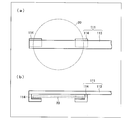
- FIG. 7A illustrates the top surface
- FIG. 7B illustrates the side surface
- the holding means 111 having a conventional configuration includes two transfer arm target holding portions 114 that support the glass laminated wafer 20 from its lower surface, and a transfer arm main body 113 that fixes each transfer arm target holding portion 114 from above. have.
- the arm portion of the transfer arm main body 113 has a flat plate structure having no opening.
- the arm portion of the transfer arm main body 113 is positioned above the glass laminated wafer 20 and straddles it so as to completely cover one diameter of the glass laminated wafer 20. It is out.
- any method can be used as long as it can suppress the temperature difference.
- a method using a holding means having an arm portion formed using a material (for example, quartz glass that transmits infrared rays), or the arm portion and the surface of the glass laminated wafer 20 when the glass laminated wafer 20 is held For example, there is a method of using a holding unit that makes the distance of the distance larger than that in the case of using a conventional arm portion.
- a material for example, quartz glass that transmits infrared rays
- FIG. 1 shows a schematic configuration of the sticking device 1 in the present embodiment.
- the sticking device 1 includes an overlapping chamber 2 and a sticking chamber 3. Both the stacking chamber 2 and the pasting chamber 3 can be depressurized.
- the stacking chamber 2 and the pasting chamber 3 have a structure in which a wall that partitions the inside of one processing chamber into two processing chambers is provided.
- a gate 4 for delivering the glass laminated wafer 20 between the overlapping chamber 2 and the pasting chamber 3 is provided at the boundary between the superposing chamber 2 and the pasting chamber 3. The opening and closing of the gate 4 is controlled by a shutter.
- the superposition chamber 2 is provided with an openable / closable delivery window 5 for delivering the glass, the wafer, and the glass laminated wafer 20 between the pasting device 1 and an external conveying means outside the pasting device 1. ing.
- Each of the overlapping chamber 2 and the pasting chamber 3 is provided with a known decompression means (not shown), and the internal pressure state of each chamber can be controlled independently.
- the affixing chamber 3 Since the affixing chamber 3 is configured to be depressurized, the wafer and glass can be bonded together via an adhesive layer in a depressurized atmosphere. By pressure bonding the wafer to the adhesive layer in a reduced pressure atmosphere, the adhesive layer can enter the recess in a state where there is no air in the recess of the uneven pattern on the wafer surface. It is possible to more reliably prevent the generation of bubbles during the interval.
- the gate 4 can move the aligned glass laminated wafer 20 from the stacking chamber 2 to the pasting chamber 3 with the shutter opened, and the pasted glass laminated wafer 20 is pasted to the pasting chamber. It is formed so that it can be moved from 3 to the superposition chamber 2.
- the shutter By opening the shutter in a state where both the superposition chamber 2 and the pasting chamber 3 are depressurized, the glass laminated wafer 20 before pasting can be moved from the superposition chamber 2 to the pasting chamber 3 under reduced pressure. ing.
- the superposition chamber 2 is a chamber for superposing the wafer and the glass, and has alignment means (not shown) for aligning the wafer and the glass.
- the affixing chamber 3 is a chamber for affixing the wafer and the glass, which have been aligned and aligned, and has an affixing means (not shown) for affixing.
- As the attaching means a configuration in which the wafer and the glass are attached by thermocompression bonding through an adhesive layer is possible.
- the sticking chamber 3 is provided with heaters at the upper and lower parts, and radiant heat is released from the heaters.
- the sticking apparatus 1 is further provided with an internal transfer means 10 for transferring the glass laminated wafer 20 between the superposition chamber 2 and the sticking chamber 3 via the gate 4.
- the internal conveyance means 10 is a structure which can move the glass laminated wafer 20 between the lamination
- the internal transfer means 10 includes an internal transfer arm (holding means) 11 and an arm pivot shaft 12.
- the internal transfer means 10 is a mechanism for moving the glass laminated wafer 20 by turning about the arm rotation shaft 12 of the internal transfer arm 11 that can support the glass laminated wafer 20 from the lower surface thereof.
- the arm turning shaft 12 is provided on the stacking chamber 2 side, but may be configured on the sticking chamber 3 side.
- the two-dot chain line indicated by “B” represents the standby position of the internal transfer arm 11
- the two-dot chain line indicated by “C” represents the position of the internal transfer arm 11 in the sticking chamber 3. Yes.
- FIG. 2 is a diagram showing the internal transfer arm 11, (a) of FIG. 2 illustrates the top surface, and (b) illustrates the side surface.
- the internal transfer arm 11 is formed by a transfer arm main body 13 and transfer arm target holding portions 14 a and 14 b provided at the lower part of the transfer arm main body 13.
- the internal transfer arm 11 is configured to hold the glass laminated wafer 20 by supporting the glass laminated wafer 20 from its lower surface by the transfer arm target holding portions 14a and 14b. Further, in a state where the glass laminated wafer 20 is held, the transfer arm main body 13 is located above the glass laminated wafer 20.
- the transfer arm body 13 of the internal transfer arm 11 has a frame shape that forms an opening as shown in FIG. More specifically, a portion of the transfer arm body 13 that overlaps the glass laminated wafer 20 is configured by a hexagonal outer frame 21 that is hollowed out inside and a reinforcing portion 22 that imparts strength to the outer frame 21. Yes.
- the reinforcing portion 22 is formed integrally with the outer frame 21 so as to connect the two points of the outer frame 21. These are connected to the arm turning shaft 12 by the arm portion 23.
- the conventional holding means 111 having the transfer arm main body 113 as shown in FIG. 7 is configured so that the transfer arm main body 113 having a flat plate structure completely covers one diameter of the glass laminated wafer 20 while the glass laminated wafer 20 is being transferred.
- the transfer arm main body 13 has a frame shape in which the portion overlapping the glass laminated wafer 20 has an opening. Therefore, the portion that shields heat from above toward the glass laminated wafer 20 is the conventional holding means 111.
- the size is small and distributed. Therefore, compared with the transfer arm main body 113 of the conventional holding means 111, the heat from above can reach the glass laminated wafer 20 more uniformly. Therefore, in the sticking apparatus 1 including the internal transfer arm 11, the temperature difference in the glass laminated wafer 20 that occurs during transfer can be reduced. And generation
- the transfer arm main body 13 has a shape that can suppress a temperature difference generated in the glass laminated wafer 20 during transfer, that is, heat from above the transfer arm main body 113 of the conventional holding unit 111 reaches the glass laminated wafer 20.
- the shape is not limited to the above shape as long as it has a shape that can be easily formed.
- a part of the hexagonal outer frame 21 of the transfer arm body 13 is removed. Examples include a configuration ((a) in FIG. 3), a configuration without the reinforcing portion 22 ((b) in FIG. 3), and the like.
- any shape can be used as long as the shape allows the heat to reach the glass laminated wafer 20 more easily than the transfer arm main body 113 of the conventional holding unit 111 and functions as the transfer arm main body.
- the internal transfer arm 11 has a configuration in which the transfer arm target holding portions 14a and 14b support and hold the glass laminated wafer 20 at three points.
- the transfer arm target holding portions 14a and 14b support and hold the glass laminated wafer 20 at three points.
- it supports at three points, it should just be supported at at least three points, for example, the structure supported at four points may be sufficient.
- the two transfer arm target holding portions 14a and 14b have different shapes.
- the transfer arm target holding portion 14a located on the side closer to the arm pivot 12 is a flat plate member having a square shape when viewed from above, and the glass laminated wafer 20 is attached to the transfer arm target holding portion 14a.
- One supporting point 19 is provided.
- the transfer arm target holding portion 14b located on the side far from the arm turning shaft 12 is a so-called arch-shaped member as viewed from above, and both tip portions of the arch shape are respectively provided. Is provided with a support point 19.
- the support point 19 is a part that contacts the glass laminated wafer 20 in the transfer arm target holding portions 14a and 14b.
- Each support point 19 is provided at a position that does not overlap the transfer arm body 13 in the vertical direction.
- the internal transfer arm that supports and holds the glass laminated wafer 20 at three points as compared with the conventional holding means 111 having a configuration in which the transfer arm target holding unit 114 holds the surface from the lower surface of the glass laminated wafer 20 at two locations. By using 11, the degree of warpage of the glass laminated wafer 20 caused by holding can be suppressed.
- FIG. 4 shows a temperature profile at each point in the glass laminated wafer 20 when the conventional holding means 111 is used for conveyance.
- the heat from the upper side is shielded at the position overlapping the transfer arm main body 113 in the glass laminated wafer 20, and therefore compared with the position not overlapping the transfer arm main body 113. , The temperature goes down. Therefore, as shown in FIG. 4, a temperature difference occurs in the glass laminated wafer 20.
- the temperature difference between the points in the glass laminated wafer 20 is 4 ° C. before transport and increases to 12 ° C. after transport.
- the temperature difference between the points in the glass laminated wafer 20 is smaller than when the conventional holding means 111 is used.
- the temperature difference in the glass laminated wafer 20 is 1 ° C. before transfer and remains at 4 ° C. even after transfer.
- the warp amount was 535 ⁇ m when transported using the conventional holding means 111, whereas the internal transport arm 11 was used for transport. In this case, the warping amount was suppressed to 103.1 ⁇ m.
- the result of the measurement of the temperature profile and the measurement of the amount of warpage is a result of measuring the glass laminated wafer 20 having a diameter of 300 mm.
- the internal transfer arm 11 in the present embodiment also has a configuration different from the conventional holding means 111 with respect to the transfer arm target holding unit 14. That is, the transfer arm target holding portion 114 of the conventional holding means 111 is configured to hold the glass laminated wafer 20 from the lower surface thereof at two locations, whereas in the internal transfer arm 11, the transfer arm target holding portion.
- Reference numeral 14 denotes a configuration for supporting and holding the glass laminated wafer 20 at three points. Therefore, the conventional holding unit 111 (also referred to as a normal hand in this paragraph) or the transfer arm target holding unit 114 of the conventional holding unit 111 is laminated with glass like the transfer arm target holding unit 14 of the internal transfer arm 11.
- the glass laminated wafer 20 is transferred and glass stacking is performed.
- the amount of warpage generated on the wafer 20 was measured.
- the transfer arm body is a flat plate-like member.
- the amount of warpage generated in the glass laminated wafer 20 was 590.8 ⁇ m, whereas when the three-point hand was used, the amount of warpage was 269.6 ⁇ m. It was reduced to.
- the curvature which arises in the glass laminated wafer 20 can also be suppressed by changing the support method of the glass laminated wafer 20 to three-point support. Accordingly, the configuration of the transfer arm target holding unit 14 also contributes to the reduction in the amount of warping when the transfer is performed using the internal transfer arm 11.
- the internal transfer arm 11 including the transfer arm main body having a shape that allows heat to reach the glass laminated wafer 20 more easily than the transfer arm main body 113 of the conventional holding unit 111 The amount of warpage that occurs can be suppressed. Further, by supporting and holding the glass laminated wafer 20 at at least three points, it is possible to further suppress the amount of warpage that occurs during conveyance.
- the transfer method in the present embodiment is a method in which the glass laminated wafer 20 is internally transferred via the gate 4 between the overlapping chamber 2 and the adhesive chamber 3 in the above-described application device 1. Is used to carry the glass laminated wafer 20 internally.
- the conveyance method in the present embodiment is the same as the conventional conveyance method (for example, the method described in Patent Document 2) except that the internal conveyance arm 11 is used as the internal conveyance means in the sticking device 1. .
- the sticking method in the present embodiment is such that the wafer and the glass are superposed in the superposition chamber 2 of the sticking device 1, and the glass laminated wafer 20 obtained thereby is transferred to the sticking chamber 3 of the sticking device 1,
- the wafer and the glass are attached in the attaching chamber 3, and the internal transfer arm 11 is used to internally transfer the glass laminated wafer 20 to the attaching chamber 3.
- the pasting method in the present embodiment is the same as the conventional pasting method (for example, the method described in Patent Document 2) except that the internal transport arm 11 is used as the internal transport means in the pasting apparatus 1.
- the configuration of the pasting device 1 in the present embodiment other than the above-described points can be the same as that of a conventionally known pasting device (for example, the pasting device described in Patent Document 2). .
- FIG. 5 shows a side surface of the internal transfer arm 15 used in the transfer method in the present embodiment.
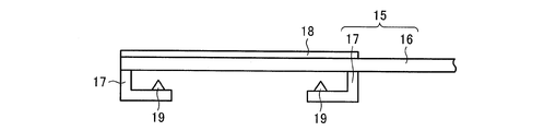
- the transfer method in the present embodiment as holding means for holding while suppressing the temperature difference generated in the glass laminated wafer 20 during transfer, two transfer arm object holding units 17 that support the glass laminated wafer 20 from the lower surface thereof,
- An internal transfer arm 15 including a transfer arm main body 16 that fixes each transfer arm target holding unit 17 from above is used.
- a heater 18 is provided on the upper surface of the portion of the transfer arm body 16 that overlaps the glass laminated wafer 20.
- the shape of the portion of the transfer arm main body 16 that overlaps the glass laminated wafer 20 is a flat plate structure having no opening.
- the glass laminated wafer 20 can be transferred while heating the transfer arm body 16 in the portion overlapping the glass laminated wafer 20 during the transfer of the glass laminated wafer 20.
- the part in the glass laminated wafer 20 where heat is shielded by the transfer arm body 16 having a flat plate structure can be forcibly heated. Therefore, as shown below, the temperature difference generated in the glass laminated wafer 20 can be reduced as compared with the case where the conveyance is performed using the conventional holding unit 111.
- the glass laminated wafer 20 is supported and held at two points.
- the glass laminated wafer 20 is transferred during the transfer process.
- the temperature at a plurality of points was measured.
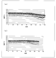
- FIG. 6A shows a temperature profile in the glass laminated wafer 20 when the conventional holding means 111 is used for transfer
- FIG. 6B shows a transfer method according to the present embodiment using the heater 18.
- the temperature profile of the glass laminated wafer 20 at the time of conveying by is shown. As shown in FIG.
- the glass laminated wafer 20 is conveyed using the internal conveyance arm 15 having the heater 18, the glass laminated wafer 20 is contained in the glass laminated wafer 20 as compared with the case where the glass laminated wafer 20 is conveyed using the conventional holding unit 111.
- the resulting temperature difference is reduced. This is because the heater 18 is provided in the transfer arm body 16 and the transfer arm body 16 is heated, so that heat is more applied to the portion of the glass laminated wafer 20 overlapping the transfer arm body 16 than in the case where the heater 18 is not provided. This is to convey a lot.
- the temperature difference between each point in the glass laminated wafer 20 is 4 degreeC before conveyance, and has risen to 12 degreeC after conveyance.
- the temperature difference between the points in the glass laminated wafer 20 is 0.6 ° C. before transport and remains at 4.2 ° C. even after transport.
- the amount of warpage was 500 ⁇ m, whereas the amount of warpage was transported by the transport method of this embodiment. In this case, the warping amount was suppressed to 100 ⁇ m.
- the temperature difference generated in the glass laminated wafer 20 can be reduced by heating the transfer arm body 16 using the heater 18. Therefore, by carrying using the internal transfer arm 11 in the present embodiment, the temperature difference generated in the glass laminated wafer 20 can be reduced, and the amount of warpage that occurs during transfer can be suppressed.
- the present invention can suppress warpage that occurs when a laminate of a substrate and a support is conveyed, it can be widely used in the field of manufacturing industrial products.
Landscapes
- Container, Conveyance, Adherence, Positioning, Of Wafer (AREA)
Abstract
基板と支持体との積層体における反りの発生を抑えた搬送方法を提供するため、本発明に係る搬送方法は、重ね合わせ室(2)と、貼付室(3)との間で、ガラス積層ウエハ(20)の搬送を行う搬送方法であって、搬送中にガラス積層ウエハ(20)内に生じる温度差を抑制しながら保持する保持手段を用いて、ガラス積層ウエハ(20)を搬送する。
Description
本発明は、重ね合わせた基板と支持体との積層体の搬送に用いられる搬送方法、ならびに当該積層体の基板と支持体との貼り付けを行う貼付方法および貼付装置に関する。
携帯電話、デジタルAV機器およびICカード等の高機能化に伴い、搭載される半導体シリコンチップ(以下、チップ)を小型化および薄板化することによって、パッケージ内にチップを高集積化する要求が高まっている。パッケージ内のチップの高集積化を実現するためには、チップの厚さを25~150μmの範囲にまで薄くする必要がある。
しかしながら、チップのベースとなる半導体ウエハ(以下、ウエハ)は、研削することにより薄板化され、その強度は弱くなり、ウエハにクラックまたは反りが生じやすくなる。また、薄板化することによって強度が弱くなったウエハを自動搬送することは困難であるため、人手によって搬送しなければならず、その取り扱いが煩雑であった。
そのため、研削するウエハにサポートプレートと呼ばれる、ガラスまたは硬質プラスチック等からなるプレートを貼り合わせることによって、ウエハの強度を保持し、クラックの発生およびウエハの反りを防止するウエハサポートシステムが開発されている。ウエハサポートシステムによりウエハの強度を維持することができるため、薄板化した半導体ウエハの搬送を自動化することができる。
ウエハとサポートプレートとは、粘着テープ、熱可塑性樹脂および接着剤等を用いて貼り合わせられている。サポートプレートが貼り付けられたウエハを薄板化した後、ウエハをダイシングする前にサポートプレートを基板から剥離する。
ウエハにサポートプレートを貼り合わせる手段としては、貼り合わせ装置がある。この貼り合わせ装置は、接着剤をウエハに塗布する塗布ユニット、接着剤を加熱して硬化させるベークユニット、ウエハとサポートプレートとを貼り合わせる貼り合わせユニット等により構成されている。さらに特許文献1には、ウエハとサポートプレートとを貼り合わせる前にウエハとサポートプレートとを所定位置で重ね合わせる、重ね合わせユニットを備えた貼り合わせ装置が開示されている。また、特許文献2には、ウエハとガラスとの位置合わせを行うロードロック室と、ウエハとガラスとの貼り合わせを行う接合室と、ガラス積層ウエハをロードロック室から接合室に減圧下で移動させる内部搬送手段を備えた貼り合わせ装置が開示されている。
本発明者らが検討した結果、ウエハとガラスとを重ね合わせたガラス積層ウエハの内部搬送を行う内部搬送手段として、内部搬送手段の一部がガラス積層ウエハの一直径を覆うような構成を有する内部搬送手段を用いた場合には、搬送を行う間に、ガラス積層ウエハに反りが発生することが判明した。具体的には、ガラス積層ウエハにおいて内部搬送手段に支持されている箇所からより離れているところの円周部付近が、鉛直下方に下がる(もしくは鉛直上方に上がる)ように反りが発生していた。
そこで、本発明は上記の問題点に鑑みてなされたものであり、その主たる目的は、搬送対象物に生じる反りを抑えた搬送方法を提供することにある。
本発明に係る搬送方法は、上記課題を解決するために、基板と支持体との重ね合わせを行う重ね合わせ室と、重ね合わせた該基板と該支持体との貼り付けを行う貼付室との間で、上記重ね合わせた該基板と該支持体との積層体の搬送を行う搬送方法であって、搬送中に上記積層体内に生じる温度差を抑制しながら保持する保持手段を用いて、上記積層体を搬送する構成を有している。
また、本発明に係る貼付方法は、基板を支持体に貼り付ける貼付方法であって、重ね合わせ室において基板と支持体との重ね合わせを行う重ね合わせ工程と、重ね合わせ工程により得られた上記基板と上記支持体との積層体を、上記基板と上記支持体との貼り付けを行う貼付室に搬送する搬送工程と、上記貼付室において上記基板と上記支持体との貼り付けを行う貼付工程とを含み、上記搬送工程では、上述の搬送方法を用いて上記積層体の搬送を行う構成を有している。
また、本発明に係る貼付装置は、基板と支持体との重ね合わせを行う重ね合わせ室、重ね合わせた上記基板と上記支持体との貼り付けを行う貼付室、および、上記重ね合わせ室と上記貼付室との間で、上記重ね合わせた上記基板と上記支持体との積層体の搬送を行う搬送手段を備えており、上記搬送手段は、上記積層体を鉛直下方から支持する支持部と、該支持部を鉛直上方から固定するアーム部とを備えた保持手段を有しており、上記アーム部は、開口部を形成する枠形状を有している構成を有している。
本発明に係る搬送方法では、搬送中に積層体内に生じる温度差を抑制しながら保持する保持手段を用いて積層体を搬送するため、積層体に生じる反りを抑えることができる。
以下に説明する本発明の実施形態では、ウエハサポートシステムのためにサポートプレートであるガラス(支持板)にウエハ(基板)を一時的に貼り合わせる処理の一工程を例に挙げて説明するが、これに限定されるものではない。なお、本明細書では、ウエハとガラスとを重ね合わせたものを「ガラス積層ウエハ」と呼ぶ。また、本明細書において、上方とは、「鉛直上方」のことを指し、「下方」とは、「鉛直下方」のことを指す。
本発明に係る搬送方法の一実施形態は、ウエハとガラスとの重ね合わせを行う重ね合わせ室と、重ね合わせたウエハとガラスとの貼り付けを行う貼付室との間で、ガラス積層ウエハの搬送を行う搬送方法であって、搬送中にガラス積層ウエハに生じる温度差を抑制しながら保持する保持手段を用いて、ガラス積層ウエハを搬送する方法である。
本明細書において「搬送中にガラス積層ウエハ内に生じる温度差を抑制する」とは、従来構成の保持手段を用いてガラス積層ウエハを保持して搬送を行う場合と比較して、ガラス積層ウエハ内に生じる温度差が低減していることを意味する。従来構成の保持手段の一例を図7に示す。図7の(a)は上面を図示しており、(b)は側面を図示している。従来構成の保持手段111は、ガラス積層ウエハ20をその下面から支持する二つの搬送アーム対象保持部114と、各搬送アーム対象保持部114を上方から固定する搬送アーム本体113とを備えている構成を有している。搬送アーム本体113のアーム部分は、開口部を有さない平板構造である。この保持手段111がガラス積層ウエハ20を保持している状態において、搬送アーム本体113のアーム部分は、ガラス積層ウエハ20の上方に位置し、ガラス積層ウエハ20の一直径を完全に覆うように跨いでいる。
搬送中にガラス積層ウエハ20内に生じる温度差を抑制する方法に特に制限はなく、温度差を抑制できる方法であれば、いかなる方法も用いることができる。例えば、ガラス積層ウエハ20内に生じる温度差を抑制することができる形状を有するアーム部分を備えた保持手段を用いる方法、アーム部分にヒーターを設ける方法、従来のアーム部分よりも熱を透過させやすい材質(例えば、赤外線を透過させる石英ガラス等)を用いて形成されたアーム部分を備えた保持手段を用いる方法、あるいは、ガラス積層ウエハ20を保持したときの、アーム部分とガラス積層ウエハ20表面との距離が、従来のアーム部分を用いる場合よりも大きくなる保持手段を用いる方法等が挙げられる。以下、本発明の具体的な実施の形態について説明する。
〔実施の形態1〕
まず、本実施形態の搬送方法が用いられる貼付装置について図1を参照して説明する。
まず、本実施形態の搬送方法が用いられる貼付装置について図1を参照して説明する。
図1は、本実施形態における貼付装置1の概略構成を示している。図1に示されるように、貼付装置1は、重ね合わせ室2および貼付室3を含んで構成されている。重ね合わせ室2および貼付室3は、いずれも減圧可能である。重ね合わせ室2および貼付室3は、一つの処理室の内部を二つの処理室に仕切る壁を設けた構造となっている。重ね合わせ室2および貼付室3の境界には、重ね合わせ室2および貼付室3間でガラス積層ウエハ20の受け渡しを行うためのゲート4が設けられている。ゲート4はシャッターによって開閉が制御されている。また、重ね合わせ室2には、貼付装置1と貼付装置1の外部にある外部搬送手段との間でガラス、ウエハおよびガラス積層ウエハ20の受け渡しを行うための開閉可能な受け渡し窓5が設けられている。重ね合わせ室2および貼付室3にはそれぞれ、公知の減圧手段が設けられており(図示せず)、各室の内部圧の状態を独立に制御することができる。
貼付室3が減圧可能な構成であるため、減圧雰囲気下においてウエハとガラスとを接着剤層を介して貼り合わせることができる。減圧雰囲気下において接着剤層にウエハを圧着させることによって、ウエハ表面の凹凸パターンの窪みに空気が存在しない状態において、接着剤層を当該窪みに入り込ませることができるため、接着剤層とウエハとの間の気泡の発生をより確実に防止することが可能である。
ゲート4は、シャッターが開いた状態で、位置合わせがなされたガラス積層ウエハ20を重ね合わせ室2から貼付室3に移動させることができるように、また、貼付後のガラス積層ウエハ20を貼付室3から重ね合わせ室2に移動させることができるように形成されている。重ね合わせ室2および貼付室3の何れも減圧させた状態でシャッターを開けることにより、貼付前のガラス積層ウエハ20を重ね合わせ室2から貼付室3に減圧下で移動させることができる構造となっている。
重ね合わせ室2は、ウエハとガラスとの重ね合わせを行う室であり、ウエハとガラスとの位置合わせを行う位置合わせ手段(不図示)を有している。貼付室3は、位置合わせを行って重ね合わされたウエハとガラスとの貼り付けを行う室であり、貼り付けを行うための貼り付け手段(不図示)を有している。貼り付け手段としては、ウエハとガラスとを接着剤層を介して熱圧着により貼り合わせる構成が可能である。貼付室3は、その上部および下部にヒーターが取り付けられており、ヒーターから輻射熱が放出されている。
貼付装置1にはさらにゲート4を介して重ね合わせ室2および貼付室3間でガラス積層ウエハ20の受け渡しを行う内部搬送手段10が設けられている。内部搬送手段10は、ガラス積層ウエハ20を重ね合わせ室2と貼付室3との間で移動させることができる構成である限り、具体的な機構に特に制限はない。本実施の形態では、図1に示すように、内部搬送手段10は、内部搬送アーム(保持手段)11およびアーム旋回軸12によって構成されている。内部搬送手段10は、ガラス積層ウエハ20をその下面から支持できる内部搬送アーム11のアーム旋回軸12を回転中心とした回動によって、ガラス積層ウエハ20を移動させる機構となっている。アーム旋回軸12は重ね合わせ室2側に設けられているが、貼付室3側に設けられた構成であってもよい。図1中、「B」で示す二点鎖線は、内部搬送アーム11の待機位置を表しており、「C」で示す二点鎖線は、内部搬送アーム11の貼付室3での位置を表している。
図2は、内部搬送アーム11を示す図であり、図2の(a)は上面を図示しており、(b)は側面を図示している。図2に示されるように、内部搬送アーム11は、搬送アーム本体13と、搬送アーム本体13の下部に設けられている搬送アーム対象保持部14a・14bとによって形成されている。内部搬送アーム11は、搬送アーム対象保持部14a・14bによって、ガラス積層ウエハ20を、その下面から支持することによって保持する構成となっている。また、ガラス積層ウエハ20を保持している状態において、搬送アーム本体13は、ガラス積層ウエハ20の上方に位置している。
内部搬送アーム11の搬送アーム本体13は、図2の(a)に示されるように、開口部を形成する枠形状を有している。より詳細には、搬送アーム本体13のうち、ガラス積層ウエハ20と重なる部分が、内部がくりぬかれた六角形の外枠21と、外枠21に強度を付与する補強部22とによって構成されている。補強部22は、外枠21の二点を結ぶように外枠21と一体的に形成されている。そしてアーム部23によってこれらがアーム旋回軸12と連結されている。
上述のように、貼付室3には、その上部および下部にヒーターが取り付けられており、ヒーターから輻射熱が放出されている。図7に示すような搬送アーム本体113を有する従来構成の保持手段111は、ガラス積層ウエハ20を搬送している間、平板構造の搬送アーム本体113がガラス積層ウエハ20の一直径を完全に覆うように跨いでいるため、この部分においてガラス積層ウエハ20への熱が遮蔽されてしまい、ガラス積層ウエハ20内において温度差が生じることになる。これに対し、搬送アーム本体13は、ガラス積層ウエハ20と重なる部分が開口部を有する枠形状であるため、上方からガラス積層ウエハ20に向かう熱を遮蔽してしまう部分が、従来の保持手段111の搬送アーム本体113と比較して、小さく、分散している。そのため、従来の保持手段111の搬送アーム本体113と比較して、上方からの熱をより均一にガラス積層ウエハ20内に到達させることができる。従って、内部搬送アーム11を備える貼付装置1においては、搬送中に生じるガラス積層ウエハ20内の温度差を小さくすることができる。そして、ガラス積層ウエハ20内の温度差が小さくなることにより、ガラス積層ウエハ20の反りの発生が抑えられる。
なお、搬送アーム本体13は、搬送中にガラス積層ウエハ20内に生じる温度差を抑制できる形状、すなわち、従来の保持手段111の搬送アーム本体113よりも上方からの熱をガラス積層ウエハ20に到達させやすい形状を有していればよく、上記の形状に限定されるものではない。本実施の形態における搬送アーム本体13の別の態様としては、図3に示すように、搬送アーム本体13の六角形の外枠21の一部(六角形の一辺に相当)が取り除かれている構成(図3の(a))、補強部22を有していない構成(図3の(b))等が挙げられる。ほかにも、従来の保持手段111の搬送アーム本体113よりも熱をガラス積層ウエハ20に到達させやすい形状であり、搬送アーム本体として機能するものであれば、いかなる形状も用いることができる。
内部搬送アーム11は、搬送アーム対象保持部14a・14bが三点においてガラス積層ウエハ20を支持して保持する構成を有している。本実施形態では、三点において支持しているが、少なくとも三点において支持すればよく、例えば、四点において支持する構成であってもよい。
本実施形態では、二つの搬送アーム対象保持部14aおよび14bは、互いに異なる形状を有している。二つある搬送アーム対象保持部のうち、アーム旋回軸12に近い側に位置する搬送アーム対象保持部14aは、上方から見た形状が四角である平板状の部材であり、ガラス積層ウエハ20を支持する支持点19が一つ設けられている。一方、二つある搬送アーム対象保持部のうち、アーム旋回軸12に遠い側に位置する搬送アーム対象保持部14bは、上方から見た形状がいわゆる弓形の部材であり、弓形の両先端部それぞれに支持点19が設けられている。支持点19は、搬送アーム対象保持部14a・14bにおいてガラス積層ウエハ20と接触する部位である。また、各支持点19は、鉛直方向において、搬送アーム本体13と重ならない位置に設けられている。
搬送アーム対象保持部114がガラス積層ウエハ20の2箇所においてその下面から面保持する構成を有する従来の保持手段111と比較して、三点においてガラス積層ウエハ20を支持して保持する内部搬送アーム11を用いることにより、保持することによって生じるガラス積層ウエハ20の反りの程度を抑制することができる。
次に、貼付装置1の内部搬送アーム11を用いてガラス積層ウエハ20の搬送を行った場合の作用について説明する。まず、内部搬送アーム11を用いてガラス積層ウエハ20を搬送した場合と、アーム部分が開口部を有さない平板構造である従来構成の保持手段111を用いて搬送した場合のそれぞれにおいて、搬送工程中、ガラス積層ウエハ20内の複数の点における温度を測定した。その結果を図4に示す。図4は、従来構成の保持手段111を用いて搬送した場合のガラス積層ウエハ20内の各点の温度プロファイルを示す。上述のように、従来の保持手段111を用いた場合、ガラス積層ウエハ20における搬送アーム本体113と重なる位置では、上方からの熱が遮蔽されるため、搬送アーム本体113と重ならない位置と比べて、温度が低くなる。そのため、図4に示されるように、ガラス積層ウエハ20内において温度差が生じることになる。従来の保持手段111を用いて搬送を行った場合、ガラス積層ウエハ20内の各点の間の温度差は、搬送前では4℃であり、搬送後では12℃に上昇している。
一方、内部搬送アーム11を用いた場合、ガラス積層ウエハ20内の各点の間の温度差は、従来の保持手段111を用いた場合よりも小さくなっている。内部搬送アーム11を用いた場合、ガラス積層ウエハ20内での温度差は、搬送前では1℃であり、搬送後でも4℃に留まっている。
さらに、これらのガラス積層ウエハ20について反り量を測定した結果、従来の保持手段111を用いて搬送した場合には、反り量は535μmであったのに対して、内部搬送アーム11を用いて搬送した場合には、反り量は103.1μmまで抑制されていた。なお、温度プロファイルの測定および反り量の測定の結果は、直径300mmのガラス積層ウエハ20に関して測定を行った結果である。
ところで、本実施の形態における内部搬送アーム11は、搬送アーム対象保持部14に関しても、従来の保持手段111と異なる構成を有している。すなわち、従来の保持手段111の搬送アーム対象保持部114がガラス積層ウエハ20を2箇所においてその下面から面保持する構成となっているのに対して、内部搬送アーム11では、搬送アーム対象保持部14が、三点においてガラス積層ウエハ20を支持して保持する構成である。そこで、従来の保持手段111(本段落においては、ノーマルハンドともいう)、または従来の保持手段111の搬送アーム対象保持部114を、内部搬送アーム11の搬送アーム対象保持部14のようにガラス積層ウエハ20を三点で支持する搬送アーム対象保持部114’に置き換えた、保持手段111’(本段落においては、三点ハンドともいう)を用いて、ガラス積層ウエハ20の搬送を行い、ガラス積層ウエハ20に生じる反り量を測定した。なお、いずれも、搬送アーム本体は、平板状の部材である。測定の結果、ノーマルハンドを用いた場合には、ガラス積層ウエハ20に生じた反り量は590.8μmであったのに対して、三点ハンドを用いた場合には、反り量は269.6μmに低減されていた。このように、ガラス積層ウエハ20の支持方法を三点支持に変更することによっても、ガラス積層ウエハ20に生じる反りを抑えることができる。したがって、内部搬送アーム11を用いて搬送を行った場合の反り量の低下には、搬送アーム対象保持部14の構成も寄与している。
以上のように、従来の保持手段111の搬送アーム本体113よりも熱をガラス積層ウエハ20に到達させやすい形状を有する搬送アーム本体を含む内部搬送アーム11を用いて搬送を行うことにより、搬送時に生じる反り量を抑えることができる。また、ガラス積層ウエハ20を少なくとも三点で支持して保持することにより、搬送時に生じる反り量をさらに抑えることができる。
本実施の形態における搬送方法は、上述の貼付装置1における重ね合わせ室2と貼付室3との間で、ゲート4を介してガラス積層ウエハ20の内部搬送を行う方法であり、内部搬送アーム11を用いて、ガラス積層ウエハ20の内部搬送を行うものである。本実施の形態における搬送方法は、貼付装置1における内部搬送手段として内部搬送アーム11を用いている点を除いて、従来の搬送方法(例えば、特許文献2に記載された方法)と同様である。また、本実施の形態における貼付方法は、貼付装置1の重ね合わせ室2においてウエハとガラスとの重ね合わせ、これにより得られたガラス積層ウエハ20を、貼付装置1の貼付室3に搬送し、貼付室3においてウエハとガラスとの貼り付けを行う方法であり、内部搬送アーム11を用いて、ガラス積層ウエハ20の貼付室3への内部搬送を行うものである。本実施の形態における貼付方法は、貼付装置1における内部搬送手段として内部搬送アーム11を用いている点を除いて、従来の貼付方法(例えば、特許文献2に記載された方法)と同様である。さらに、本実施の形態における貼付装置1の上記した点以外の構成については、従来公知の貼付装置(例えば、特許文献2に記載された貼り合わせ装置)と同様の構成とすることが可能である。
〔実施の形態2〕
本発明に係る搬送方法の第2の実施形態について説明する。なお、説明の便宜上、前述の実施の形態で用いたものと同じ機能を有する部材には同じ参照符号を付して、その説明を省略する。本実施形態における搬送方法は、搬送の際にガラス積層ウエハ20を保持する内部搬送アームの構成が、上述の実施形態における内部搬送アーム11と異なっている。その他の構成については、上述の実施形態における構成と同じである。
本発明に係る搬送方法の第2の実施形態について説明する。なお、説明の便宜上、前述の実施の形態で用いたものと同じ機能を有する部材には同じ参照符号を付して、その説明を省略する。本実施形態における搬送方法は、搬送の際にガラス積層ウエハ20を保持する内部搬送アームの構成が、上述の実施形態における内部搬送アーム11と異なっている。その他の構成については、上述の実施形態における構成と同じである。
本実施形態における搬送方法において用いている内部搬送アーム15の側面を図5に示す。本実施形態における搬送方法では、搬送中にガラス積層ウエハ20内に生じる温度差を抑制しながら保持する保持手段として、ガラス積層ウエハ20をその下面から支持する二つの搬送アーム対象保持部17と、各搬送アーム対象保持部17を上方から固定する搬送アーム本体16とを備えた内部搬送アーム15を用いている。搬送アーム本体16のガラス積層ウエハ20と重なる部分の上面には、ヒーター18が設けられている。搬送アーム本体16のガラス積層ウエハ20と重なる部分の形状は、上述の実施形態における搬送アーム本体13と異なり、開口部を有さない平板構造である。本実施形態における搬送方法によれば、ガラス積層ウエハ20の搬送中に、ガラス積層ウエハ20と重なる部分における搬送アーム本体16を加熱しながら、ガラス積層ウエハ20を搬送することができる。これにより、ガラス積層ウエハ20内の、平板構造の搬送アーム本体16によって熱が遮蔽される部分を強制的に温めることができる。そのため、次に示すように、従来の保持手段111を用いて搬送を行った場合と比較して、ガラス積層ウエハ20内に生じる温度差を小さくすることができる。なお、本実施形態の搬送方法では、第1の実施形態における搬送方法と異なり、ガラス積層ウエハ20を二点で支持し、保持している。
ヒーター18を有する内部搬送アーム15を用いてガラス積層ウエハ20を搬送した場合と、ヒーターが設けられていない従来の保持手段111を用いて搬送した場合のそれぞれにおいて、搬送工程中、ガラス積層ウエハ20内の複数の点における温度を測定した。結果を図6に示す。図6の(a)は、従来の保持手段111を用いて搬送した場合のガラス積層ウエハ20内の温度プロファイルを示し、図6の(b)は、ヒーター18を用いた本実施形態の搬送方法により搬送した場合のガラス積層ウエハ20の温度プロファイルを示す。図6に示されるように、ヒーター18を有する内部搬送アーム15を用いてガラス積層ウエハ20を搬送した場合には、従来の保持手段111を用いて搬送した場合よりも、ガラス積層ウエハ20内に生じる温度差が小さくなる。これは、搬送アーム本体16にヒーター18を設け、搬送アーム本体16を加熱することにより、ヒーター18を設けない場合と比較して、ガラス積層ウエハ20における搬送アーム本体16と重なる部分に熱がより多く伝わるためである。なお、従来の保持手段111を用いて搬送した場合、ガラス積層ウエハ20内の各点の間の温度差は、搬送前では4℃であり、搬送後に12℃に上昇している。一方、本実施形態の搬送方法により搬送した場合、ガラス積層ウエハ20内の各点の間の温度差は、搬送前では0.6℃であり、搬送後でも4.2℃に留まっている。
さらに、これらのガラス積層ウエハ20の反り量を測定した結果、従来の保持手段111を用いて搬送した場合には、反り量は500μmであったのに対して、本実施形態の搬送方法により搬送した場合には、反り量は100μmまで抑制されていた。
以上のように、本実施形態における内部搬送アーム11では、ヒーター18を用いて搬送アーム本体16を加熱することで、ガラス積層ウエハ20に生じる温度差を小さくすることができる。そのため、本実施形態における内部搬送アーム11を用いて搬送を行うことにより、ガラス積層ウエハ20に生じる温度差を小さくすることができ、搬送時に生じる反り量を抑えることができる。
本発明は上述した実施形態に限定されるものではなく、請求項に示した範囲で種々の変更が可能である。すなわち、請求項に示した範囲で適宜変更した技術的手段を組み合わせて得られる実施形態についても本発明の技術的範囲に含まれる。
本発明は、基板および支持体の積層体を搬送する際に生じる反りを抑制することができるため、工業製品の製造分野に幅広く利用することができる。
1 貼付装置
2 重ね合わせ室
3 貼付室
4 ゲート
10 内部搬送手段
11、15 内部搬送アーム
12 アーム旋回軸
13、16 搬送アーム本体
14a、14b、17 搬送アーム対象保持部
18 ヒーター
19 支持点
20 ガラス積層ウエハ
21 外枠
22 補強部
23 アーム部
2 重ね合わせ室
3 貼付室
4 ゲート
10 内部搬送手段
11、15 内部搬送アーム
12 アーム旋回軸
13、16 搬送アーム本体
14a、14b、17 搬送アーム対象保持部
18 ヒーター
19 支持点
20 ガラス積層ウエハ
21 外枠
22 補強部
23 アーム部
Claims (9)
- 基板と支持体との重ね合わせを行う重ね合わせ室と、重ね合わせた該基板と該支持体との貼り付けを行う貼付室との間で、上記重ね合わせた該基板と該支持体との積層体の搬送を行う搬送方法であって、
搬送中に上記積層体内に生じる温度差を抑制しながら保持する保持手段を用いて、上記積層体を搬送することを特徴とする搬送方法。 - 上記保持手段は、上記積層体を鉛直下方から支持する支持部と、該支持部を鉛直上方から固定するアーム部とを備えており、
上記アーム部は、搬送中に上記積層体内に生じる温度差を抑制することができる形状を有していることを特徴とする請求項1に記載の搬送方法。 - 上記アーム部は、開口部を形成する枠形状を有していることを特徴とする請求項2に記載の搬送方法。
- 上記支持部における上記積層体と接触する部位は、鉛直方向において上記アーム部と重ならない位置に設けられていることを特徴とする請求項2または3に記載の搬送方法。
- 上記保持手段は、少なくとも三点において上記積層体を支持して保持することを特徴とする請求項1~4の何れか1項に記載の搬送方法。
- 基板を支持体に貼り付ける貼付方法であって、
重ね合わせ室において基板と支持体との重ね合わせを行う重ね合わせ工程と、
重ね合わせ工程により得られた上記基板と上記支持体との積層体を、上記基板と上記支持体との貼り付けを行う貼付室に搬送する搬送工程と、
上記貼付室において上記基板と上記支持体との貼り付けを行う貼付工程とを含み、
上記搬送工程では、請求項1~5の何れか1項に記載の搬送方法を用いて上記積層体の搬送を行うことを特徴とする貼付方法。 - 基板と支持体との重ね合わせを行う重ね合わせ室、
重ね合わせた上記基板と上記支持体との貼り付けを行う貼付室、および、
上記重ね合わせ室と上記貼付室との間で、上記重ね合わせた上記基板と上記支持体との積層体の搬送を行う搬送手段を備えており、
上記搬送手段は、上記積層体を鉛直下方から支持する支持部と、該支持部を鉛直上方から固定するアーム部とを備えた保持手段を有しており、
上記アーム部は、開口部を形成する枠形状を有していることを特徴とする貼付装置。 - 上記支持部における上記積層体と接触する部位は、鉛直方向において上記アーム部と重ならない位置に設けられていることを特徴とする請求項7に記載の貼付装置。
- 上記保持手段は、少なくとも三点において上記積層体を支持して保持するものであることを特徴とする請求項7または8に記載の貼付装置。
Applications Claiming Priority (2)
| Application Number | Priority Date | Filing Date | Title |
|---|---|---|---|
| JP2012-218717 | 2012-09-28 | ||
| JP2012218717A JP2014072459A (ja) | 2012-09-28 | 2012-09-28 | 搬送方法、貼付方法および貼付装置 |
Publications (1)
| Publication Number | Publication Date |
|---|---|
| WO2014050494A1 true WO2014050494A1 (ja) | 2014-04-03 |
Family
ID=50387902
Family Applications (1)
| Application Number | Title | Priority Date | Filing Date |
|---|---|---|---|
| PCT/JP2013/074047 Ceased WO2014050494A1 (ja) | 2012-09-28 | 2013-09-06 | 搬送方法、貼付方法および貼付装置 |
Country Status (3)
| Country | Link |
|---|---|
| JP (1) | JP2014072459A (ja) |
| TW (1) | TW201420470A (ja) |
| WO (1) | WO2014050494A1 (ja) |
Families Citing this family (1)
| Publication number | Priority date | Publication date | Assignee | Title |
|---|---|---|---|---|
| JP7347267B2 (ja) * | 2020-03-03 | 2023-09-20 | 三菱電機株式会社 | 半導体製造装置 |
Citations (4)
| Publication number | Priority date | Publication date | Assignee | Title |
|---|---|---|---|---|
| JPH11207594A (ja) * | 1997-11-05 | 1999-08-03 | Aplex Inc | モジュール式ウエハ研磨装置及びウエハ研磨方法 |
| JP2001035903A (ja) * | 1999-05-28 | 2001-02-09 | Applied Materials Inc | ウェーハ・ハンドリング装置用組立体 |
| JP2004327934A (ja) * | 2003-04-28 | 2004-11-18 | Applied Materials Inc | ウェハブレード |
| JP2012059758A (ja) * | 2010-09-06 | 2012-03-22 | Tokyo Ohka Kogyo Co Ltd | 貼り合わせ装置および貼り合わせ方法 |
-
2012
- 2012-09-28 JP JP2012218717A patent/JP2014072459A/ja active Pending
-
2013
- 2013-09-06 WO PCT/JP2013/074047 patent/WO2014050494A1/ja not_active Ceased
- 2013-09-12 TW TW102133000A patent/TW201420470A/zh unknown
Patent Citations (4)
| Publication number | Priority date | Publication date | Assignee | Title |
|---|---|---|---|---|
| JPH11207594A (ja) * | 1997-11-05 | 1999-08-03 | Aplex Inc | モジュール式ウエハ研磨装置及びウエハ研磨方法 |
| JP2001035903A (ja) * | 1999-05-28 | 2001-02-09 | Applied Materials Inc | ウェーハ・ハンドリング装置用組立体 |
| JP2004327934A (ja) * | 2003-04-28 | 2004-11-18 | Applied Materials Inc | ウェハブレード |
| JP2012059758A (ja) * | 2010-09-06 | 2012-03-22 | Tokyo Ohka Kogyo Co Ltd | 貼り合わせ装置および貼り合わせ方法 |
Also Published As
| Publication number | Publication date |
|---|---|
| TW201420470A (zh) | 2014-06-01 |
| JP2014072459A (ja) | 2014-04-21 |
Similar Documents
| Publication | Publication Date | Title |
|---|---|---|
| JP4781802B2 (ja) | サポートプレートの貼り合わせ手段及び貼り合わせ装置、並びにサポートプレートの貼り合わせ方法 | |
| CN105960703B (zh) | 用于结合基体的方法及装置 | |
| TWI663677B (zh) | 搬運方法及黏貼裝置 | |
| KR101821853B1 (ko) | 중첩 장치 및 중첩 방법 | |
| CN103632997B (zh) | 层叠方法以及层叠系统 | |
| TWI493647B (zh) | 接合裝置、接合方法、程式及電腦記憶媒體 | |
| JP6014302B2 (ja) | 貼り合わせ装置および貼り合わせ方法 | |
| KR101677864B1 (ko) | 중첩 장치 및 중첩 방법 | |
| KR101710221B1 (ko) | 기판 처리 장치 및 기판 처리 방법 | |
| WO2014050494A1 (ja) | 搬送方法、貼付方法および貼付装置 | |
| TWI763696B (zh) | 黏貼裝置 | |
| TWI701755B (zh) | 黏貼系統、及黏貼方法 | |
| JP2010010247A (ja) | 基板搬送用治具、及び素子基板の製造方法 | |
| JP2005340390A (ja) | 半導体装置の製造装置及び製造方法 | |
| JP2010050265A (ja) | ウェーハの搬送用パッド | |
| JP2008281851A (ja) | 液晶表示パネル製造装置 | |
| KR101315411B1 (ko) | 유기발광소자 봉지장치 및 유기발광소자 봉지방법 | |
| KR20140012929A (ko) | 기판합착방법 |
Legal Events
| Date | Code | Title | Description |
|---|---|---|---|
| 121 | Ep: the epo has been informed by wipo that ep was designated in this application |
Ref document number: 13842004 Country of ref document: EP Kind code of ref document: A1 |
|
| NENP | Non-entry into the national phase |
Ref country code: DE |
|
| 122 | Ep: pct application non-entry in european phase |
Ref document number: 13842004 Country of ref document: EP Kind code of ref document: A1 |