WO2014050413A1 - エアバッグ装置 - Google Patents
エアバッグ装置 Download PDFInfo
- Publication number
- WO2014050413A1 WO2014050413A1 PCT/JP2013/072961 JP2013072961W WO2014050413A1 WO 2014050413 A1 WO2014050413 A1 WO 2014050413A1 JP 2013072961 W JP2013072961 W JP 2013072961W WO 2014050413 A1 WO2014050413 A1 WO 2014050413A1
- Authority
- WO
- WIPO (PCT)
- Prior art keywords
- airbag
- inflator
- slit
- patch
- front pillar
- Prior art date
- Legal status (The legal status is an assumption and is not a legal conclusion. Google has not performed a legal analysis and makes no representation as to the accuracy of the status listed.)
- Ceased
Links
Images











Classifications
-
- B—PERFORMING OPERATIONS; TRANSPORTING
- B60—VEHICLES IN GENERAL
- B60R—VEHICLES, VEHICLE FITTINGS, OR VEHICLE PARTS, NOT OTHERWISE PROVIDED FOR
- B60R21/00—Arrangements or fittings on vehicles for protecting or preventing injuries to occupants or pedestrians in case of accidents or other traffic risks
- B60R21/34—Protecting non-occupants of a vehicle, e.g. pedestrians
- B60R21/36—Protecting non-occupants of a vehicle, e.g. pedestrians using airbags
Definitions
- the present invention belongs to the technical field of an airbag device for inflating and deploying outside a vehicle by a gas from an inflator in an emergency such as when a vehicle collides with a collision target and to mitigate a shock applied to the collision target or the vehicle. Is.
- an airbag is inflated outside the pillar portion of the vehicle to alleviate the impact of the pedestrian or the like re-colliding with the vehicle.
- the inflator is installed in the front pillar.
- An airbag device is disclosed (see Patent Document 1).
- the present invention has been made in view of such circumstances, and the object thereof is to be configured in a small size, to increase the degree of freedom of design of the front pillar, and to be easily assembled to the front pillar and in a stable state. It is providing the airbag apparatus which catches a pedestrian etc. appropriately and softly by inflating.
- an airbag apparatus includes an airbag that can be inflated by gas by sewing a base fabric, and a body that is attached to the inside of the base fabric of the airbag, And an inflator that ejects, wherein the inflator is attached to the inside, and the folded airbag is disposed on a decorative member disposed on the front pillar or around the front pillar outside the vehicle.
- the airbag has a slit for inserting the inflator.
- the inflator has a mounting portion protruding from the main body, the airbag has mounting holes on both sides of the slit, and the mounting portion of the inflator is inserted through the mounting hole of the airbag. It is characterized by doing.
- a slit for inserting the inflator and a patch member having attachment holes on both sides of the slit are provided, and the attachment hole of the airbag and the attachment hole of the patch member are attached in an overlapping manner.
- the slit of the airbag and the slit of the patch member are different in angle with respect to a predetermined direction.
- the inflator is attached to the inside, and a cover that covers the folded airbag is modularized.
- the base fabric of the airbag has a protrusion that forms an L-shape, and includes a protector cloth that is disposed at least between the protrusion and the vehicle when the airbag is inflated.
- an airbag that can be inflated by gas by sewing a base fabric, and an inflator in which a main body is attached to the inside of the base fabric of the airbag and jets gas. And the inflator is attached to the inside, and the folded airbag is arranged on the decorative member arranged on the front pillar or the periphery of the front pillar outside the vehicle. It is possible to provide an airbag device that increases the degree of freedom and is easy to assemble with respect to the front pillar and inflates in a stable state so that a pedestrian or the like is appropriately and softly received.
- the airbag has a slit for inserting the inflator, the inflator can be easily inserted into the airbag.
- the inflator has a mounting portion protruding from the main body, the airbag has mounting holes on both sides of the slit, and the mounting portion of the inflator is inserted through the mounting hole of the airbag. Since the inflator is installed on the slit after inserting the gas, it is possible to reduce gas leakage after expansion.
- a slit for inserting the inflator and a patch member having attachment holes on both sides of the slit are provided, and the attachment holes of the airbag and the attachment holes of the patch member are attached in an overlapping manner. Can be increased.
- the slit of the airbag and the slit of the patch member are different in angle with respect to a predetermined direction, it is possible to reduce gas leakage when the airbag is inflated.
- the inflator is attached to the inside and a cover that covers the folded airbag is modularized, it can be easily assembled to the front pillar.
- the base fabric of an airbag has the protrusion part which forms L shape, and is equipped with the protector cloth arrange
- FIG. 11 shows the airbag 11 of 1st Embodiment. It is a figure which shows the inflator 12 and the inflator support member 13 of 1st Embodiment. It is a figure which shows the state which inserts the inflator 12 and the inflator support member 13 in the airbag 11 of 1st Embodiment. It is a figure which permeate
- FIG. 2 is an exploded view of the vicinity of a mounting portion 12b of the inflator 12 of the airbag module 10.
- FIG. It is a figure which shows the other example of the slit 11b of the airbag 11, and the attachment hole 11c vicinity. It is a figure which shows the other example of the state which folded the airbag 11 of 1st Embodiment. It is a figure which shows the expansion part of the cover 14 and module cover 15 of 1st Embodiment. It is a figure which shows the state which the airbag 11 of 1st Embodiment inflated.
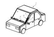
- 1 is a perspective view of a vehicle 1 equipped with an airbag device 10 of a first embodiment.
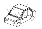
- FIG. 1 is a perspective view of a vehicle 1 in a state where an airbag device 10 according to a first embodiment is inflated. It is the figure which expanded the vicinity of the airbag apparatus 10 of FIG.
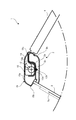
- FIG. 15 is a cross-sectional view of the vicinity of the front pillar of the vehicle according to the first embodiment.
- FIG. 2 is a cross-sectional view of the airbag 11 when inflated when the shape of the front pillar 2 of the vehicle 1 is different. It is a figure which shows the process in which the inflator 12 and the inflator support member 13 are inserted in the airbag 11 of 2nd Embodiment, and it folds.
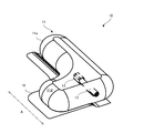
- FIG. 1 is a view showing an airbag 11 according to the first embodiment.
- FIG. 1A is an overall view of the airbag 11.
- FIG. 1B is an enlarged view of the vicinity of the slit viewed from the back side of the airbag 11.
- the airbag 11 of the first embodiment is formed in a balloon shape by sewing the base fabric 11a, has a substantially elliptical shape, and is inflated by injecting gas into the inside.
- the airbag 11 relieves an impact with a collision target such as a pedestrian during inflation.
- the airbag 11 includes a base fabric 11a, a slit 11b, and a mounting hole 11c.
- the slit 11b is obtained by cutting a part of the base fabric 11a, and is a portion into which an inflator or the like described later is inserted.
- the slit 11 b of the first embodiment is preferably formed in a direction of about 45 ° with respect to the longitudinal direction A of the airbag 11.
- the attachment hole 11c is a hole into which an inflator attachment portion described later is inserted.
- the attachment holes 11c are preferably formed along the longitudinal direction A of the airbag 11 at least as many as the attachment portions of the inflator. By providing the attachment hole 11c along the longitudinal direction A of the airbag 11, it can be aligned in the longitudinal direction of the tubular inflator, and the airbag 11 can be stably held.
- FIG. 2 is a diagram illustrating the inflator 12 and the inflator support member 13 according to the first embodiment.
- the inflator 12 includes an inflator body 12a and an attachment portion 12b for attachment to the front pillar.
- the inflator main body 12a is a cylinder in which compressed gas is filled, and the airbag 11 is inflated by flowing gas into the airbag 11.
- the attachment portion 12b is a rod-like member protruding from the inflator body 12a, and is attached to the inflator 12 by being inserted into a vehicle body such as a front pillar. It is preferable to provide at least two attachment portions 12b so that they can be stably attached to the vehicle body.
- the inflator support member 13 is formed in a cylindrical shape with a mounting portion 13a for mounting the inflator main body 12a and a cylindrical portion having an opening on the mounting portion 13a side adjacent to the mounting portion 13a, and a storage portion 13b for storing the inflator main body 12a. And having. A notch 13c is formed on the side of the mounting portion 13a opposite to the storage portion 13b.
- the inflator 12 and the inflator support member 13 insert the attachment portion 12b of the inflator 12 into the notch 13c of the inflator support member 13, place the inflator body 12a on the placement portion 13a, and then place the inflator 12 on the inflator support member 13. It is possible to easily assemble by simply inserting from the placement portion 13a side to the storage portion 13b side.
- FIG. 3 is a view showing a state in which the inflator 12 and the inflator support member 13 are inserted into the airbag 11 of the first embodiment.
- FIG. 4 is a view showing the state after the inflator 12 and the inflator support member 13 are inserted into the airbag 11 of the first embodiment, through the airbag 11.
- the inflator 12 and the inflator support member 13 are integrally inserted from the slit 11 b of the airbag 11.
- the attachment portion 12 b of the inflator 12 is inserted into the attachment hole 11 c of the airbag 11 as shown in FIG. 4. Therefore, the inflator 12 and the inflator support member 13 are disposed inside the airbag 11 except for the attachment portion 12 b of the inflator 12.
- the inflator 12 can be easily inserted into the airbag 11.
- the inflator 12 has a mounting portion 12b protruding from the main body, the airbag 11 has mounting holes 11c on both sides of the slit 11b, and the mounting portion 12b of the inflator 12 has a mounting hole 11c in the airbag 11. Since it is inserted, since the inflator 12 is installed on the slit 11b after the inflator 12 is inserted into the airbag 11, gas leakage after inflation can be reduced.
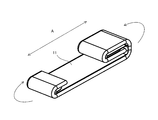
- FIG. 5 is a view showing a state in which the airbag 11 of the first embodiment is folded after the inflator 12 and the inflator support member 13 are inserted.
- the folding method may be a roll or a bellows.
- the airbag 11 is configured to be folded after the inflator 12 and the inflator support member 13 are inserted, the airbag 11 is small in size and can have a high degree of freedom in designing the mounting portion and can be easily assembled. Become.
- FIG. 6 is a diagram showing the airbag apparatus 10 according to the first embodiment.
- FIG. 7 is an exploded view of the vicinity of the attachment portion 12 b of the inflator 12 of the airbag device 10.
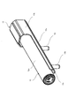
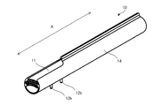
- the airbag device 10 is a module in which the airbag 11 in a folded state is covered with a cover 14 after the inflator 12 and the inflator support member 13 are inserted, and is modularized.
- the cover 14 has a cover body 14a, a mounting hole 14b, and an expanded portion 14c.
- the attachment hole 14b is a hole through which the attachment portion 12b of the inflator 12 is inserted.
- the expansion portion 14 c is a portion that expands the cover body 14 a when the airbag 11 is inflated.
- the folded airbag 11 is attached to the attachment portion 13 b of the inflator support member 13.
- the cover body 14a is inserted through the cover 14b, and the widened portion 14c is sewn.
- the cover 14 is provided with the inflator 12 attached to the inside and the airbag 11 in a folded state covering the folded airbag 11, the assembly can be facilitated.
- FIG. 8 is a view showing another example of the vicinity of the slit 11b and the attachment hole 11c of the airbag 11. As shown in FIG.
- the first patch 11 1 and the second patch 11 2 are stacked in the vicinity of the slit 11 b and the attachment hole 11 c of the airbag 11.
- 8 (a) is, the airbag 11 is a diagram showing the stacked state of the first patch 11 1 and the second patch 11 2, FIG. 8 (b), the slit 11b of the air bag 11, first patch slit 11 is a diagram showing a state of 1 b and the second patch slit 11 2 b.
- the first patch 11 1 is an order of magnitude of the slits 11b and the attachment holes 11c of the air bag 11 is covered, a first patch body 11 1 a using a thin film of the same material as the base fabric 11a, the air
- the first patch slit 11 1 b is formed at an angle that intersects the slit 11 b of the bag 11 near the center, and the first patch hole 11 1 c is inserted through the attachment portion 12 b of the inflator 12.
- the second patch 11 2 is an order of magnitude of the slits 11b and the attachment holes 11c of the air bag 11 is covered, and a second patch body 11 2 a using a thin film of the same material as the base fabric 11a, the air
- the second patch slit 11 2 b formed at an angle that intersects the slit 11 b of the bag 11 and the first patch slit 11 1 b of the first patch 11 1 in the vicinity of the center, and the attachment portion 12 b of the inflator 12 are inserted.
- Second patch holes 11 2 c Second patch holes 11 2 c.
- the slits 11b and the vicinity of the base fabric 11a of the mounting hole 11c of the air bag 11, first patch body 11 1 a, and the second patch body 11 2 a are mounted superimposed .
- a slit 11b, the first patch slit 11 1 b and the second patch slit 11 2 b of the air bag 11 is different angles.
- the slit 11b of the airbag 11 is inclined by 45 ° with respect to the direction A
- the first patch slit 11 1 b is inclined by 45 ° with respect to the direction A in the opposite direction to the slit 11b.
- 11 2 b is provided at 90 ° with respect to the direction A.
- the gap between the inner side and the outer side of the base fabric 11a of the airbag 11 is linear.
- the gap common to the 1 patch slit 11 1 b and the second patch slit 11 2 b is only the center point O where each slit overlaps.
- the airbag 11, the first patch 11 1, and the second patch 11 2 are stacked from the top. That is, the first patch 11 1 and the second patch 11 2 are laminated on the outside of the airbag 11.
- the order is not limited to this, and for example, the first patch 11 1 and the second patch 11 2 may be stacked inside the airbag 11.
- one of the first patch 11 1 and the second patch 11 2 may be laminated on the inside and the other on the outside. That is, the order of stacking need not be specified.
- FIG. 9 is a view showing another example of the folded state of the airbag 11 of the first embodiment.
- the airbag 11 is folded so that the length in the direction A of the airbag 11 is further shortened from the folded state as shown in FIG.
- the airbag 11 can accommodate more compactly and it becomes possible to make the module of the airbag apparatus 10 small.
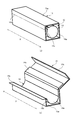
- FIG. 10 is a view showing the cover 14 and the storage member 15 of the first embodiment. 10A shows a state where the cover 14 and the storage member 15 are closed, and FIG. 10B shows a state where the cover 14 and the storage member 15 are open. However, only the cover 14 of the airbag device 10 is shown, and the rest is omitted.
- the airbag device 10 shown in FIG. 6 is stored in a storage member 15 as a decorative member.
- the storage member 15 may be, for example, an exterior part or a pillar structure attached to the pillar, and includes a storage member main body 15a and an expanded portion 15b.
- the storage member body 15 a is a member that stores the airbag device 10.
- the expansion part 15b is a part that expands when the airbag is inflated.
- the widened portion 14c of the cover 14 and the widened portion 15b of the storage member 15 are preferably disposed in substantially the same direction with respect to the airbag (not shown).
- the expanded portion 14c of the cover 14 and the expanded portion 15b of the storage member 15 are shown in FIG. And the expansion position of the expansion part 15b of the storage member 15 becomes substantially the same. Therefore, when the airbag is inflated, the expanded portion 14c of the cover 14 and the expanded portion 15b of the storage member 15 can be expanded smoothly. Further, when the cover 14 is configured to cover the expanded portion 15 b of the storage member 15 during the expansion, it is possible to reduce damage to the airbag by the expanded portion 15 b of the storage member 15.
- FIG. 11 is a view showing a state where the airbag 11 of the first embodiment is inflated.
- the gas When gas is generated from the inflator 12 due to detection of impact or the like, the gas is ejected from the inflator 12, and the airbag 11 is inflated as shown in FIG. When the airbag 11 is inflated, the cover 14 extends below the airbag 11.
- the inflator 12 is arrange
- the piping between the inflator 12 and the airbag 11 becomes unnecessary, and the airbag apparatus 10 of 1st Embodiment does not need an airbag. 11 can be shortened. Further, when the airbag 11 is inflated, the cover 14 expands below the airbag 11, so that interference between the airbag 11 and other members can be reduced.
- FIG. 12 is a perspective view of the vehicle 1 equipped with the airbag device 10 of the first embodiment.
- FIG. 13 is a cross-sectional view of the vicinity of the front pillar of the vehicle according to the first embodiment.
- 1 is a vehicle
- 2 is a front pillar
- 3 is a windshield
- 4 is a door
- 10 is an airbag device
- 12 is an inflator
- 14 is a cover
- 15 is a storage member.
- the vehicle 1 has a front pillar 2 that connects a roof or a member or an engine room frame (not shown). Moreover, it has the windshield 3 enclosed by the food
- the front pillar 2 includes a frame pillar 2 a that forms a vehicle body, an interior pillar 2 b that forms an interior material on the vehicle compartment side, and a storage member 15 in which the airbag device 10 is stored. .
- the airbag device 10 is attached by inserting the attachment portion 12b protruding from the inflator 12 into the attachment hole 2c of the frame pillar 2a and fixing with a nut or the like.
- the storage member 15 includes a storage member main body 15a, an expanded portion 15b, a bent portion 15c capable of bending the storage member main body 15a, and an insertion hole 15d through which the attachment portion 12b protruding from the inflator 12 is inserted.
- the storage member 15 is inserted into the mounting hole 2c of the frame pillar 2a with the mounting portion 12b protruding from the inflator 12 inserted into the insertion hole 15d, and fixed by a nut or the like. It is attached. That is, the airbag device 10 is housed in the front pillar 2 of the vehicle 1 in a module state in which the inflator 12 is built in the airbag.
- the airbag device 10 is housed in the front pillar 2 of the vehicle 1 in a module state in which the inflator 12 is built in the airbag, it is possible to reduce the size and improve the ease of assembly.
- FIG. 14 is a perspective view of the vehicle 1 in a state where the airbag device 10 of the first embodiment is inflated.
- FIG. 15 is an enlarged view of the vicinity of the airbag device 10 of FIG.
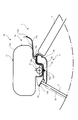
- FIG. 16 is a sectional view of the vicinity of the front pillar of the vehicle according to the first embodiment.
- the airbag apparatus 10 in the storage state as shown in FIGS. 12 and 13 detects when the vehicle 1 collides with a collision target (not shown) and the impact force generated on the vehicle 1 is detected by a detection unit (not shown) or the like. Based on the signal, it is operated by a control unit or the like.
- the airbag 11 In the stage where inflation is completed, the airbag 11 is deployed in the direction along the front pillar 2 in front of the front pillar 2. Also, as shown in FIG. 16, at the stage of completion of inflation, the airbag 11 is restricted in the direction of inflation by the storage member 15 in front of the front pillar 2 and toward the windshield 3.
- the airbag 11 since the airbag 11 is restricted in the direction of inflation by the storage member 15 in front of the front pillar 2 and in the direction of the windshield 3, when the airbag 11 collides with a collision target such as a pedestrian, the airbag 11 Escape to the outside of the front pillar 2, which is the direction opposite to the windshield 3, can be reduced, and a collision target can be received in front of the front pillar 2.
- the distance from the surface of the windshield 3 to the tip of the expanded portion 15b of the storage member 15 adjacent to the windshield 3 is from the surface of the windshield 3 to the wiper rubber. It is preferable that it is larger than the distance to the upper end of 5a.
- FIG. 17 is a cross-sectional view of the airbag 11 when inflated when the shape of the front pillar 2 of the vehicle 1 is different.
- the front pillar 2 shown in FIG. 17 does not have the storage member 15 shown in FIG. 16, and uses only exterior parts (not shown). That is, the front pillar 2 shown in FIG. 17 includes a frame pillar 2a that forms a vehicle body, and an interior pillar 2b that forms an interior material on the vehicle interior side.
- the airbag device 10 is attached by inserting the attachment portion 12b protruding from the inflator 12 into the attachment hole 2c of the frame pillar 2a and fixing with a nut or the like.
- the frame pillar 2a has a recess 2d that houses the airbag device 10 before inflation.
- the airbag device 10 can be stored in the recess 2d, and it is not necessary to use the storage member 15, and only an exterior part that covers the recess 2d is used. It is possible to improve the assembling property at a low cost.
- FIG. 18 is a diagram showing a process of inserting and folding the inflator 12 and the inflator support member 13 into the airbag 11 of the second embodiment.
- the airbag 11 of the second embodiment uses an L-shaped base fabric 11a. Therefore, the folding method is slightly different from that of the first embodiment.
- the inflator 12 and the inflator support member 13 are integrally inserted from the slit 11b of the airbag 11, and the attachment portion 12b of the inflator 12 is inserted into the attachment hole 11c of the airbag 11. It is inserted. Therefore, the inflator 12 and the inflator support member 13 are disposed inside the airbag 11 except for the attachment portion 12 b of the inflator 12.
- the inflator 12 and the inflator are projected from the end of the protrusion 11 d that protrudes in a direction intersecting the A direction of the L-shaped base fabric 11 a of the airbag 11.
- the part up to the support member 13 is folded.
- the protrusion 11d protruding in a direction intersecting with the A direction of the L-shaped base fabric 11a of the airbag 11 is folded into a rectangular shape as a whole.
- the folding method may be a roll or a bellows.
- FIG. 19 is a view showing a state when the airbag 11 of the second embodiment is inflated.
- the airbag 11 of 2nd Embodiment uses the L-shaped base fabric 11a which has the protrusion 11d. Therefore, when used in the vehicle 1 shown in FIG. 14, when the airbag 11 is inflated, the protrusion 11 d may protrude above the windshield 3 and interfere with the wiper 5.
- the protector cloth 16 is provided between the airbag 11 and the cover 14.
- the protector cloth 16 is L-shaped like the base cloth 11 a of the airbag 11.
- the distance from the surface of the windshield 3 to the tip of the widened portion 15b of the storage member 15 adjacent to the windshield 3 is 3 is preferably larger than the distance from the surface of 3 to the upper end of the wiper rubber 5a.
- the airbag 11 of 2nd Embodiment uses a L-shaped base fabric 11a, and can expand a pedestrian etc. appropriately and softly by expanding to a wide range in a more stable state. It becomes possible to catch it.
- the protector cloth 16 disposed between the projection 11d and the vehicle is used to reduce interference of the base fabric 11a of the airbag 11 with the wiper 5. It becomes possible. Further, it is possible to reduce the damage of the wiper 5 by the base cloth 11a when the airbag 11 is inflated.
- FIG. 20 is a diagram illustrating Example 1 in which the airbag 11 according to the second embodiment is folded.
- Example 1 of the method of folding the airbag 11 according to the second embodiment folds the airbag 11 in a bellows shape, and the protector cloth 16 is placed so as to surround the folded airbag 11. Fold it up.
- FIG. 21 is a diagram illustrating Example 2 of the airbag 11 according to the second embodiment in a folded state.
- Example 2 of the method for folding the airbag 11 of the second embodiment folds the airbag 11 and the protector cloth 16 together in a bellows shape as shown in FIG.
- FIG. 22 is a diagram illustrating Example 3 of the airbag 11 in the folded state according to the second embodiment.
- Example 3 of the method of folding the airbag 11 of the second embodiment as shown in FIG. 22, the airbag 11 and the protector cloth 16 are both folded in a roll shape so as to surround the folded airbag 11. Fold the protector cloth 16.
- FIG. 23 is a diagram illustrating a fourth example of the airbag 11 in the folded state according to the second embodiment.
- Example 4 of the method of folding the airbag 11 of the second embodiment as shown in FIG. 23, the protector cloth 16 is folded so as to fold the airbag 11 and surround the folded airbag 11. Fold it up.
- the airbag 11 that can be inflated by gas by sewing the base fabric 11a and the main body 12a can be attached to the inside of the base fabric 11a of the airbag 11.
- the inflator 12 for injecting gas, the inflator 12 is attached to the inside, and the airbag 11 in a folded state is disposed on the front pillar 2 or the storage member 15 disposed around the front pillar outside the vehicle.
- An airbag device that is compact and has a high degree of freedom in designing the front pillar 2 and that is easy to assemble to the front pillar 2 and inflates in a stable state to appropriately and softly accept pedestrians and the like. 10 can be provided.
- the airbag 11 has the slit 11b for inserting the inflator 12, the inflator 12 can be easily inserted into the airbag 11.
- the inflator 12 has a mounting portion 12b protruding from the main body, the airbag 11 has mounting holes 11c on both sides of the slit 11b, and the mounting portion 12b of the inflator 12 has a mounting hole 11c in the airbag 11. Since it is inserted, since the inflator 12 is installed on the slit 11b after the inflator 12 is inserted into the airbag 11, gas leakage after inflation can be reduced.
- the inflator 12 is attached to the inside and the cover 14 that covers the folded airbag 11 and is modularized is provided, the assembly to the front pillar 2 is facilitated.
- the base fabric 11a of the airbag 11 has a protrusion 11d that forms an L-shape, and when the airbag 11 is inflated, a protector cloth 16 that is disposed at least between the protrusion 11d and the windshield 3 is provided. Since it is provided, it is possible to appropriately and softly catch pedestrians and the like by expanding in a wide range in a more stable state, and reducing the interference of the base fabric 11a of the airbag 11 with the wiper 5 It becomes possible to do.
- the airbag device of the present invention configured in a small size, increases the degree of freedom in designing the front pillar 2, and is easily assembled to the front pillar 2, and is inflated in a stable state. Thus, it is possible to appropriately and softly catch pedestrians and the like.
Landscapes
- Engineering & Computer Science (AREA)
- Mechanical Engineering (AREA)
- Air Bags (AREA)
Description
本発明は、車両が衝突対象と衝突した時等の緊急時に、インフレータからのガスにより車両外部に膨張展開して、衝突対象や車両にかかる衝撃を緩和するためのエアバッグ装置の技術分野に属するものである。
従来、車両と歩行者等との衝突時に、エアバッグを車両のピラー部分の外側に膨張させ、該歩行者等が車両と再衝突する衝撃を緩和させるものがある。
例えば、走行中の車両が歩行者に衝突した際に、歩行者が車体のフロントピラーと二次衝突する際の衝撃を吸収緩和するピラーエアバッグ装置において、インフレータをフロントピラー内に設置しているエアバッグ装置が開示されている(特許文献1参照)。
しかしながら、特許文献1に記載されたエアバッグ装置では、インフレータのサイズ及び形状にあわせてフロントピラーにインフレータの収納部を形成する必要があり、フロントピラーの設計に制約を与えてしまっていた。
本発明は、このような事情に鑑みてなされたものであって、その目的は、小型に構成され、フロントピラーの設計の自由度を高くすると共に、フロントピラーに対する組み付け性が良く、安定な状態で膨張することで歩行者等を適切に、且つ、ソフトに受け止めるエアバッグ装置を提供することである。
前述の課題を解決するために、本発明にかかるエアバッグ装置は、基布を縫製してガスにより膨張可能なエアバッグと、本体を前記エアバッグの前記基布の内側に取り付けられ、ガスを噴出するインフレータと、を備え、前記インフレータを内側に取り付け、折り畳んだ状態の前記エアバッグを、車両外側でフロントピラーもしくはフロントピラー周辺に配置された加飾部材に配置することを特徴とする。
また、前記エアバッグは、前記インフレータを挿入するスリットを有することを特徴とする。
また、前記インフレータは、前記本体から突出した取付部を有し、前記エアバッグは、前記スリットの両側に取付孔を有し、前記インフレータの前記取付部は、前記エアバッグの前記取付孔を挿通することを特徴とする。
また、前記インフレータを挿入するスリット及び前記スリットの両側に取付孔を有するパッチ部材を備え、前記エアバッグの前記取付孔と前記パッチ部材の前記取付孔とを重ねて取り付けることを特徴とする。
また、前記エアバッグの前記スリットと前記パッチ部材の前記スリットは、所定の方向に対する角度が異なることを特徴とする。
また、前記インフレータを内側に取り付け、折り畳んだ状態の前記エアバッグを覆ってモジュール化するカバーを備えることを特徴とする。
また、前記エアバッグの前記基布は、L字状を形成する突部を有し、前記エアバッグの膨張時に、少なくとも前記突部と車両との間に配置されるプロテクタクロスを備えることを特徴とする。
このように構成された本発明に係るエアバッグ装置によれば、基布を縫製してガスにより膨張可能なエアバッグと、本体をエアバッグの基布の内側に取り付けられ、ガスを噴出するインフレータと、を備え、インフレータを内側に取り付け、折り畳んだ状態のエアバッグを、車両外側でフロントピラーもしくはフロントピラー周辺に配置された加飾部材に配置するので、小型に構成され、フロントピラーの設計の自由度を高くすると共に、フロントピラーに対する組み付け性が良く、安定な状態で膨張することで歩行者等を適切に、且つ、ソフトに受け止めるエアバッグ装置を提供することが可能となる。
また、エアバッグは、インフレータを挿入するスリットを有するので、エアバッグ内にインフレータを容易に挿入することが可能となる。
また、インフレータは、本体から突出した取付部を有し、エアバッグは、スリットの両側に取付孔を有し、インフレータの取付部は、エアバッグの取付孔を挿通するので、エアバッグ内にインフレータを挿入した後、スリット上にインフレータが設置されるため、膨張後のガス漏れを低減することが可能となる。
また、インフレータを挿入するスリット及びスリットの両側に取付孔を有するパッチ部材を備え、エアバッグの取付孔とパッチ部材の取付孔とを重ねて取り付けるので、エアバッグのスリット及び取付孔の付近の強度を高めることが可能となる。
また、エアバッグのスリットとパッチ部材のスリットは、所定の方向に対する角度が異なるので、エアバッグの膨張時のガス漏れを低減することが可能となる。
また、インフレータを内側に取り付け、折り畳んだ状態のエアバッグを覆ってモジュール化するカバーを備えるので、フロントピラーへの組み付けが容易となる。
また、エアバッグの基布は、L字状を形成する突部を有し、エアバッグの膨張時に、少なくとも突部と車両との間に配置されるプロテクタクロスを備えるので、より安定な状態で広い範囲に膨張することで歩行者等を適切に、且つ、ソフトに受け止めることが可能となると共に、エアバッグの基布がワイパーと干渉することを低減することが可能となる。
以下、図面を用いて、本発明にかかるエアバッグ装置の実施形態を説明する。
図1は、第1実施形態のエアバッグ11を示す図である。図1(a)は、エアバッグ11の全体図である。図1(b)は、エアバッグ11の裏側から見たスリット付近の拡大図である。
第1実施形態のエアバッグ11は、基布11aを縫製して風船状に形成され、略楕円形の形状を有し、内側にガスを注入されることで膨張する。エアバッグ11は、膨張時に歩行者等の衝突対象との衝撃を緩和させるものである。
エアバッグ11は、基布11aと、スリット11bと、取付孔11cと、を有する。
スリット11bは、基布11aの一部に切り込みを入れたもので、後述するインフレータ等を挿入する部分である。第1実施形態のスリット11bは、エアバッグ11の長手方向Aに対して、約45°の方向で形成されることが好ましい。
取付孔11cは、後述するインフレータの取付部が挿入される孔である。取付孔11cは、エアバッグ11の長手方向Aに沿って、少なくともインフレータの取付部と同じ数、形成されることが好ましい。取付孔11cをエアバッグ11の長手方向Aに沿って設けることで、筒状のインフレータの長手方向に揃えることができ、エアバッグ11を安定して保持することが可能となる。
図2は、第1実施形態のインフレータ12及びインフレータ支持部材13を示す図である。
第1実施形態のインフレータ12は、インフレータ本体12aと、フロントピラーに対して取り付けるための取付部12bと、を有する。
インフレータ本体12aは、円筒形状の内部に圧縮ガスを充填し、エアバッグ11内にガスを流入させてエアバッグ11を膨張させるものである。取付部12bは、インフレータ本体12aから突出した棒状の部材であり、フロントピラー等の車体に挿通してインフレータ12を取り付けるものである。取付部12bは、車体に対して安定して取り付けられるように、少なくとも2つ設けることが好ましい。
インフレータ支持部材13は、インフレータ本体12aを載置する載置部13aと、載置部13aに隣接し載置部13a側を開口させた筒状に形成され、インフレータ本体12aを収納する収納部13bと、を有する。載置部13aの収納部13bとは反対側には、切り込み13cが形成されている。
インフレータ12とインフレータ支持部材13は、インフレータ12の取付部12bをインフレータ支持部材13の切り込み13cに挿入し、インフレータ本体12aを載置部13aに載置した後、インフレータ12をインフレータ支持部材13の載置部13a側から収納部13b側へ差し込む動作だけで、簡単に組み付けることが可能となる。
図3は、第1実施形態のエアバッグ11にインフレータ12及びインフレータ支持部材13を挿入する状態を示す図である。図4は、第1実施形態のエアバッグ11にインフレータ12及びインフレータ支持部材13を挿入した後の状態を、エアバッグ11を透過して示す図である。
図3に示すように、インフレータ12及びインフレータ支持部材13は、一体となって、エアバッグ11のスリット11bから挿入される。インフレータ12及びインフレータ支持部材13をエアバッグ11に挿入した後、図4に示すように、インフレータ12の取付部12bは、エアバッグ11の取付孔11cに挿通される。したがって、インフレータ12及びインフレータ支持部材13は、インフレータ12の取付部12bを除いてエアバッグ11の内部に配置される。
すなわち、エアバッグ11は、インフレータ12を挿入するスリット11bを有するので、エアバッグ11内にインフレータ12を容易に挿入することが可能となる。また、インフレータ12は、本体から突出した取付部12bを有し、エアバッグ11は、スリット11bの両側に取付孔11cを有し、インフレータ12の取付部12bは、エアバッグ11の取付孔11cを挿通するので、エアバッグ11内にインフレータ12を挿入した後、スリット11b上にインフレータ12が設置されるため、膨張後のガス漏れを低減することが可能となる。
図5は、第1実施形態のエアバッグ11を、インフレータ12及びインフレータ支持部材13を挿入した後、折りたたんだ状態を示す図である。
インフレータ12及びインフレータ支持部材13を挿入した後、エアバッグ11は、コンパクトに折り畳まれる。折り畳み方は、ロール状に折り畳んでも、蛇腹状に折り畳んでもよい。
このように、エアバッグ11を、インフレータ12及びインフレータ支持部材13を挿入した後、折り畳む構成とするので、小型で取り付け部分の設計の自由度を高くすると共に、組み付け性を良くすることが可能となる。
図6は、第1実施形態のエアバッグ装置10を示す図である。図7は、エアバッグ装置10のインフレータ12の取付部12b付近の分解図である。
図6に示すように、エアバッグ装置10は、インフレータ12及びインフレータ支持部材13を挿入した後、折り畳んだ状態のエアバッグ11を、カバー14で覆い、モジュール化したものである。
カバー14は、カバー本体14aと、取付孔14bと、拡開部14cと、を有する。取付孔14bは、インフレータ12の取付部12bを挿通する孔である。拡開部14cは、エアバッグ11の膨張時にカバー本体14aを拡開させる部分である。
エアバッグ装置10を形成するには、図5に示したような、インフレータ12及びインフレータ支持部材13を挿入した後、折りたたんだ状態のエアバッグ11を、インフレータ支持部材13の取付部13bに取付孔14bを挿通したカバー本体14aで包み、拡開部14cを縫製する。
このように、インフレータ12を内側に取り付け、折り畳んだ状態のエアバッグ11を覆ってモジュール化するカバー14を備えるので、組み付けを容易にすることが可能となる。
図8は、エアバッグ11のスリット11b及び取付孔11c付近の他の例を示す図である。
図8に示す例では、エアバッグ11のスリット11b及び取付孔11c付近に第1パッチ111及び第2パッチ112を積層している。図8(a)は、エアバッグ11、第1パッチ111及び第2パッチ112の積層状態を示す図であり、図8(b)は、エアバッグ11のスリット11b、第1パッチスリット111b及び第2パッチスリット112bの状態を示す図である。
第1パッチ111は、エアバッグ11のスリット11b及び取付孔11cが覆われる程度の大きさであって、基布11aと同様の材料の薄膜を用いた第1パッチ本体111aと、エアバッグ11のスリット11bに対して中央付近で交差する角度に形成された第1パッチスリット111bと、インフレータ12の取付部12bが挿通される第1パッチ孔111cと、を有する。
第2パッチ112は、エアバッグ11のスリット11b及び取付孔11cが覆われる程度の大きさであって、基布11aと同様の材料の薄膜を用いた第2パッチ本体112aと、エアバッグ11のスリット11b及び第1パッチ111の第1パッチスリット111bに対して中央付近で交差する角度に形成された第2パッチスリット112bと、インフレータ12の取付部12bが挿通される第2パッチ孔112cと、を有する。
図8(a)に示すように、エアバッグ11のスリット11b及び取付孔11cの付近の基布11a、第1パッチ本体111a、及び第2パッチ本体112aは、重ねて取り付けている。
したがって、エアバッグ11のスリット11b及び取付孔11cの付近の強度を高めることが可能となる。
また、図8(b)に示すように、エアバッグ11のスリット11b、第1パッチスリット111b及び第2パッチスリット112bは、それぞれ角度が異なっている。例えば、エアバッグ11のスリット11bは、方向Aに対して45°傾斜させ、第1パッチスリット111bは、方向Aに対してスリット11bとは逆方向に45°傾斜させ、第2パッチスリット112bは、方向Aに対して90°に設けられている。
第1パッチ111及び第2パッチ112を積層せず、エアバッグ11のスリット11bのみの場合、エアバッグ11の基布11aの内側と外側の間の空隙は、線状となる。これに対して、第1パッチ111及び第2パッチ112を積層し、各スリットの角度を異ならせて設けることで、図8(b)に示すように、エアバッグ11のスリット11b、第1パッチスリット111b及び第2パッチスリット112bに共通の空隙は、各スリットの重なった中心点Oのみとなる。
したがって、エアバッグ11の膨張時のガス漏れを低減することが可能となる。
なお、図8に示した例では、上からエアバッグ11、第1パッチ111及び第2パッチ112と積層している。すなわち、エアバッグ11の外側に第1パッチ111及び第2パッチ112を積層している。しかしながら、この順に限らず、例えば、第1パッチ111及び第2パッチ112は、エアバッグ11の内側に積層してもよい。また、第1パッチ111又は第2パッチ112の一方を内側、他方を外側に積層してもよい。すなわち、積層する順番は、特定しなくてもよい。
図9は、第1実施形態のエアバッグ11を折りたたんだ状態の他の例を示す図である。
この例では、図5に示したように折り畳んだ状態から、エアバッグ11の方向Aの長さがさらに短くなるように折り畳んだものである。このように、折り畳むことによって、さらにコンパクトに収納することができ、エアバッグ装置10のモジュールを小さくすることが可能となる。
図10は、第1実施形態のカバー14と収納部材15を示す図である。図10(a)は、カバー14及び収納部材15が閉じた状態、図10(b)は、カバー14及び収納部材15が開いた状態を示す。ただし、エアバッグ装置10のうち、カバー14のみ示しており、残りは省略している。
図6に示したエアバッグ装置10は、図10(a)に示すように、加飾部材としての収納部材15に収納される。収納部材15は、例えば、ピラーに取り付けられる外装部品やピラー構造体等でよく、収納部材本体15aと、拡開部15bと、を有する。収納部材本体15aは、エアバッグ装置10を収納する部材である。拡開部15bは、エアバッグの膨張時に拡開する部分である。カバー14の拡開部14cと収納部材15の拡開部15bは、図示しないエアバッグに対してほぼ同じ方向に配置することが好ましい。
カバー14の拡開部14cと収納部材15の拡開部15bを図示しないエアバッグに対してほぼ同じ方向に配置することで、図10(b)に示すように、カバー14の拡開部14cと収納部材15の拡開部15bの拡開位置がほぼ同じとなる。したがってエアバッグの膨張時にカバー14の拡開部14cと収納部材15の拡開部15bは、円滑に拡開することが可能となる。また、拡開時に、カバー14は、収納部材15の拡開部15bを覆う構造とすることによって、収納部材15の拡開部15bでエアバッグに傷をつけることが低減される。
図11は、第1実施形態のエアバッグ11が膨張した状態を示す図である。
衝撃等の感知によってインフレータ12からガスが発生すると、インフレータ12からガスが噴出し、図11に示すように、エアバッグ11が膨張する。エアバッグ11が膨張すると、カバー14は、エアバッグ11の下方に拡がる。
このように、第1実施形態のエアバッグ装置10は、インフレータ12がエアバッグ11の基布11aの内部に配置されているので、インフレータ12とエアバッグ11の間の配管が必要なくなり、エアバッグ11の膨張の時間を短くすることが可能となる。また、エアバッグ11が膨張すると、カバー14がエアバッグ11の下方に拡がるので、エアバッグ11と他の部材との干渉を低減することが可能となる。
次に、エアバッグ装置10を車両1に搭載した状態を説明する。
図12は、第1実施形態のエアバッグ装置10を搭載した車両1の斜視図である。図13は、第1実施形態の車両のフロントピラー付近の断面図である。
図中、1は車両、2はフロントピラー、3はウインドシールド、4はドア、10はエアバッグ装置、12はインフレータ、14はカバー、15は収納部材である。
車両1は、図示しないメンバーあるいはエンジンルームフレームとルーフを連結するフロントピラー2を有する。また、フード、ルーフ及びフロントピラー2に囲まれ、シールを介して取り付けられたウインドシールド3を有する。また、フロントピラー2を挟んで、ウインドシールド3の反対側にドア4を有する。
図13に示すように、フロントピラー2は、車体を形成するフレームピラー2aと、車室側で内装材を形成する内装ピラー2bと、エアバッグ装置10が収納される収納部材15と、を有する。エアバッグ装置10は、インフレータ12から突出した取付部12bを、フレームピラー2aの取付孔2cに挿入し、ナット等によって固定することで取り付けられる。
収納部材15は、収納部材本体15aと、拡開部15bと、収納部材本体15aを折り曲げ可能な折曲部15cと、インフレータ12から突出した取付部12bが挿通する挿通孔15dと、を有する。収納部材15は、エアバッグ装置10と同様に、インフレータ12から突出した取付部12bを、挿通孔15dに挿通した状態で、フレームピラー2aの取付孔2cに挿入し、ナット等によって固定することで取り付けられる。すなわち、エアバッグ装置10は、インフレータ12をエアバッグ内に内蔵したモジュールの状態で、車両1のフロントピラー2に収納される。
このように、エアバッグ装置10は、インフレータ12をエアバッグ内に内蔵したモジュールの状態で、車両1のフロントピラー2に収納されるので、小型で組み付け性を良好にすることが可能となる。
図14は、第1実施形態のエアバッグ装置10が膨張した状態の車両1の斜視図である。図15は、図14のアバッグ装置10付近を拡大した図である。図16は、図15は第1実施形態の車両のフロントピラー付近の断面図である。
図12及び図13に示すような収納状態にあるエアバッグ装置10は、車両1が図示しない衝突対象と衝突し、車両1に発生した衝撃力を図示しない検知部等で検知した場合、その検知信号に基づき制御部等により作動される。
エアバッグ装置10は、作動を始めると、インフレータ12からエアバッグ11内にガスを流入させ、エアバッグ11を膨張させる。エアバッグ11が膨張すると、膨張圧力により、カバー14が開く。その後、エアバッグ11全体が折り畳まれた状態から完全に外部に露出する。そして、エアバッグ11は、完全に膨張する。膨張完了段階のエアバッグ装置10の状態を以下に説明する。
膨張完了段階では、エアバッグ11は、フロントピラー2の前方で、フロントピラー2に沿う方向に展開する。また、図16に示すように、膨張完了段階では、エアバッグ11は、収納部材15により、フロントピラー2の前方及びウインドシールド3の方向へ膨張方向が規制される。
このように、エアバッグ11は、収納部材15により、フロントピラー2の前方及びウインドシールド3の方向へ膨張方向が規制されるので、歩行者等の衝突対象と衝突した際に、エアバッグ11がウインドシールド3とは反対方向であるフロントピラー2の外側に逃げてしまうことを低減することができ、フロントピラー2の前方で衝突対象を受けることが可能となる。
また、図16に示すように、エアバッグ11膨張時に、ウインドシールド3の表面からウインドシールド3に隣接する収納部材15の拡開部15bの先端までの距離は、ウインドシールド3の表面からワイパーゴム5aの上端までの距離よりも大きいことが好ましい。
このように、収納部材15の拡開部15bの先端のウインドシールド3からの高さを設定することにより、エアバッグ11の基布11aとワイパー5との干渉が低減され、エアバッグ11の基布11a及びワイパー5の損傷を低減することが可能となる。
図17は、車両1のフロントピラー2の形状が異なる場合のエアバッグ11の膨張時の断面図である。
図17に示すフロントピラー2は、図16に示した収納部材15を有しておらず、図示しない外装部品のみを用いる。すなわち、図17に示すフロントピラー2は、車体を形成するフレームピラー2aと、車室側で内装材を形成する内装ピラー2bと、を有する。エアバッグ装置10は、インフレータ12から突出した取付部12bを、フレームピラー2aの取付孔2cに挿入し、ナット等によって固定することで取り付けられる。また、フレームピラー2aは、膨張前のエアバッグ装置10を内蔵する凹部2dを有する。
このような形状のフロントピラー2の場合、凹部2dにエアバッグ装置10を収納することができ、収納部材15を使用する必要がなく、凹部2dを覆う外装部品のみを使用すればよいので、低コストで、組み付け性を良好にすることが可能となる。
図18は、第2実施形態のエアバッグ11にインフレータ12及びインフレータ支持部材13を挿入し、折りたたむ過程を示す図である。
第2実施形態のエアバッグ11は、L字状の基布11aを使用する。そのため、折り畳みの方法が第1実施形態と若干異なる。
図18(a)に示すように、インフレータ12及びインフレータ支持部材13は、一体となって、エアバッグ11のスリット11bから挿入され、インフレータ12の取付部12bは、エアバッグ11の取付孔11cに挿通される。したがって、インフレータ12及びインフレータ支持部材13は、インフレータ12の取付部12bを除いてエアバッグ11の内部に配置される。
続いて、図18(b)に示すように、エアバッグ11のL字状の基布11aのA方向に対して交差する方向に突出している突部11dのうち、端部からインフレータ12及びインフレータ支持部材13までの部分を折り畳む。
続いて、図18(c)に示すように、エアバッグ11のL字状の基布11aのA方向に対して交差する方向に突出している突部11dを折り畳み全体を長方形状とする。
続いて、図18(d)に示すように、エアバッグ11は、コンパクトに折り畳まれる。折り畳み方は、ロール状に折り畳んでも、蛇腹状に折り畳んでもよい。
図19は、第2実施形態のエアバッグ11の膨張時の状態を示す図である。
第2実施形態のエアバッグ11は、突部11dを有するL字状の基布11aを使用する。そのため、図14に示した車両1に用いた場合、エアバッグ11が膨張すると、突部11dは、ウインドシールド3の上方に突出し、ワイパー5と干渉するおそれがある。
そこで、第2実施形態のエアバッグ装置10は、エアバッグ11とカバー14の間にプロテクタクロス16を設ける。プロテクタクロス16は、エアバッグ11の基布11aと同様にL字状の形状とする。
また、図16に示した第1実施形態と同様に、エアバッグ11膨張時に、ウインドシールド3の表面からウインドシールド3に隣接する収納部材15の拡開部15bの先端までの距離は、ウインドシールド3の表面からワイパーゴム5aの上端までの距離よりも大きいことが好ましい。
このように、第2実施形態のエアバッグ11は、L字状の基布11aを使用することによって、より安定な状態で広い範囲に膨張することで歩行者等を適切に、且つ、ソフトに受け止めることが可能となる。
また、この場合、エアバッグ11の膨張時に、少なくとも突部11dと車両との間に配置されるプロテクタクロス16を用いることによって、エアバッグ11の基布11aがワイパー5と干渉することを低減することが可能となる。さらに、エアバッグ11の膨張時に基布11aによってワイパー5が破損することを低減することが可能となる。
図20は、第2実施形態のエアバッグ11の折り畳み状態の実施例1を示す図である。
第2実施形態のエアバッグ11を折り畳む方法の実施例1は、図20に示すように、エアバッグ11を蛇腹状に折り畳み、折り畳まれたエアバッグ11の周囲を囲むように、プロテクタクロス16を折り畳む。
図21は、第2実施形態のエアバッグ11の折り畳み状態の実施例2を示す図である。
第2実施形態のエアバッグ11を折り畳む方法の実施例2は、図21に示すように、エアバッグ11とプロテクタクロス16を共に蛇腹状に折り畳む。
図22は、第2実施形態のエアバッグ11の折り畳み状態の実施例3を示す図である。
第2実施形態のエアバッグ11を折り畳む方法の実施例3では、図22に示すように、エアバッグ11とプロテクタクロス16を共にロール状に折り畳み、折り畳まれたエアバッグ11の周囲を囲むように、プロテクタクロス16を折り畳む。
図23は、第2実施形態のエアバッグ11の折り畳み状態の実施例4を示す図である。
第2実施形態のエアバッグ11を折り畳む方法の実施例4では、図23に示すように、エアバッグ11をロール状に折り畳み、折り畳まれたエアバッグ11の周囲を囲むように、プロテクタクロス16を折り畳む。
このように構成された本実施形態のエアバッグ装置10によれば、基布11aを縫製してガスにより膨張可能なエアバッグ11と、本体12aをエアバッグ11の基布11aの内側に取り付けられ、ガスを噴出するインフレータ12と、を備え、インフレータ12を内側に取り付け、折り畳んだ状態のエアバッグ11を、車両外側でフロントピラー2もしくはフロントピラー周辺に配置された収納部材15に配置するので、小型に構成され、フロントピラー2の設計の自由度を高くすると共に、フロントピラー2に対する組み付け性が良く、安定な状態で膨張することで歩行者等を適切に、且つ、ソフトに受け止めるエアバッグ装置10を提供することが可能となる。
また、エアバッグ11は、インフレータ12を挿入するスリット11bを有するので、エアバッグ11内にインフレータ12を容易に挿入することが可能となる。
また、インフレータ12は、本体から突出した取付部12bを有し、エアバッグ11は、スリット11bの両側に取付孔11cを有し、インフレータ12の取付部12bは、エアバッグ11の取付孔11cを挿通するので、エアバッグ11内にインフレータ12を挿入した後、スリット11b上にインフレータ12が設置されるため、膨張後のガス漏れを低減することが可能となる。
また、インフレータ12を挿入するスリット111b及びスリット111bの両側に取付孔111cを有するパッチ部材111を備え、エアバッグ11の取付孔11cとパッチ部材111の取付孔111cとを重ねて取り付けるので、エアバッグ11のスリット11b及び取付孔11cの付近の強度を高めることが可能となる。
また、エアバッグ11のスリット11bとパッチ部材111のスリット111bは、所定の方向に対する角度が異なるので、エアバッグ11の膨張時のガス漏れを低減することが可能となる。
また、インフレータ12を内側に取り付け、折り畳んだ状態のエアバッグ11を覆ってモジュール化するカバー14を備えるので、フロントピラー2への組み付けが容易となる。
また、エアバッグ11の基布11aは、L字状を形成する突部11dを有し、エアバッグ11の膨張時に、少なくとも突部11dとウインドシールド3との間に配置されるプロテクタクロス16を備えるので、より安定な状態で広い範囲に膨張することで歩行者等を適切に、且つ、ソフトに受け止めることが可能となると共に、エアバッグ11の基布11aがワイパー5と干渉することを低減することが可能となる。
このように構成された本発明に係るエアバッグ装置によれば、小型に構成され、フロントピラー2の設計の自由度を高くすると共に、フロントピラー2に対する組み付け性が良く、安定な状態で膨張することで歩行者等を適切に、且つ、ソフトに受け止めることが可能となる。
Claims (7)
- 基布を縫製してガスにより膨張可能なエアバッグと、
本体を前記エアバッグの前記基布の内側に取り付けられ、ガスを噴出するインフレータと、
を備え、
前記インフレータを内側に取り付け、折り畳んだ状態の前記エアバッグを、車両外側でフロントピラーもしくはフロントピラー周辺に配置された加飾部材に配置する
ことを特徴とするエアバッグ装置。 - 前記エアバッグは、前記インフレータを挿入するスリットを有する
ことを特徴とする請求項1に記載のエアバッグ装置。 - 前記インフレータは、前記本体から突出した取付部を有し、
前記エアバッグは、前記スリットの両側に取付孔を有し、
前記インフレータの前記取付部は、前記エアバッグの前記取付孔を挿通する
ことを特徴とする請求項2に記載のエアバッグ装置。 - 前記インフレータを挿入するスリット及び前記スリットの両側に取付孔を有するパッチ部材を備え、
前記エアバッグの前記取付孔と前記パッチ部材の前記取付孔とを重ねて取り付ける
ことを特徴とする請求項3に記載のエアバッグ装置。 - 前記エアバッグの前記スリットと前記パッチ部材の前記スリットは、所定の方向に対する角度が異なる
ことを特徴とする請求項4に記載のエアバッグ装置。 - 前記インフレータを内側に取り付け、折り畳んだ状態の前記エアバッグを覆ってモジュール化するカバーを備える
ことを特徴とする請求項1乃至5のいずれか1項に記載のエアバッグ装置。 - 前記エアバッグの前記基布は、L字状を形成する突部を有し、
前記エアバッグの膨張時に、少なくとも前記突部と車両との間に配置されるプロテクタクロスを備える
ことを特徴とする請求項1乃至6のいずれか1項に記載のエアバッグ装置。
Applications Claiming Priority (2)
| Application Number | Priority Date | Filing Date | Title |
|---|---|---|---|
| JP2012214094A JP6041602B2 (ja) | 2012-09-27 | 2012-09-27 | エアバッグ装置 |
| JP2012-214094 | 2012-09-27 |
Publications (1)
| Publication Number | Publication Date |
|---|---|
| WO2014050413A1 true WO2014050413A1 (ja) | 2014-04-03 |
Family
ID=50387822
Family Applications (1)
| Application Number | Title | Priority Date | Filing Date |
|---|---|---|---|
| PCT/JP2013/072961 Ceased WO2014050413A1 (ja) | 2012-09-27 | 2013-08-28 | エアバッグ装置 |
Country Status (2)
| Country | Link |
|---|---|
| JP (1) | JP6041602B2 (ja) |
| WO (1) | WO2014050413A1 (ja) |
Cited By (3)
| Publication number | Priority date | Publication date | Assignee | Title |
|---|---|---|---|---|
| JP2017081248A (ja) * | 2015-10-23 | 2017-05-18 | タカタ株式会社 | エアバッグ及びエアバッグ装置 |
| WO2017182013A1 (en) * | 2016-04-20 | 2017-10-26 | Havlik, Martin | Shock-absorbing device, particularly for vehicles |
| US10870402B2 (en) | 2016-04-20 | 2020-12-22 | Martin Havlik | Shock-absorbing device, particularly for vehicles |
Families Citing this family (2)
| Publication number | Priority date | Publication date | Assignee | Title |
|---|---|---|---|---|
| JP6922803B2 (ja) * | 2017-08-03 | 2021-08-18 | 豊田合成株式会社 | エアバッグ装置 |
| JP6919613B2 (ja) | 2018-03-28 | 2021-08-18 | 豊田合成株式会社 | エアバッグ装置 |
Citations (6)
| Publication number | Priority date | Publication date | Assignee | Title |
|---|---|---|---|---|
| JP2003063334A (ja) * | 2001-08-30 | 2003-03-05 | Toyota Motor Corp | 歩行者保護用エアバッグ装置 |
| JP2007203956A (ja) * | 2006-02-03 | 2007-08-16 | Takata Corp | エアバッグ及びエアバッグ装置 |
| JP2008037233A (ja) * | 2006-08-04 | 2008-02-21 | Takata Corp | フードエアバッグ装置 |
| JP2008189184A (ja) * | 2007-02-06 | 2008-08-21 | Nippon Plast Co Ltd | エアバッグ装置 |
| JP2008201266A (ja) * | 2007-02-20 | 2008-09-04 | Nippon Plast Co Ltd | エアバッグ装置 |
| JP2010149690A (ja) * | 2008-12-25 | 2010-07-08 | Toyoda Gosei Co Ltd | エアバッグ装置 |
-
2012
- 2012-09-27 JP JP2012214094A patent/JP6041602B2/ja not_active Expired - Fee Related
-
2013
- 2013-08-28 WO PCT/JP2013/072961 patent/WO2014050413A1/ja not_active Ceased
Patent Citations (6)
| Publication number | Priority date | Publication date | Assignee | Title |
|---|---|---|---|---|
| JP2003063334A (ja) * | 2001-08-30 | 2003-03-05 | Toyota Motor Corp | 歩行者保護用エアバッグ装置 |
| JP2007203956A (ja) * | 2006-02-03 | 2007-08-16 | Takata Corp | エアバッグ及びエアバッグ装置 |
| JP2008037233A (ja) * | 2006-08-04 | 2008-02-21 | Takata Corp | フードエアバッグ装置 |
| JP2008189184A (ja) * | 2007-02-06 | 2008-08-21 | Nippon Plast Co Ltd | エアバッグ装置 |
| JP2008201266A (ja) * | 2007-02-20 | 2008-09-04 | Nippon Plast Co Ltd | エアバッグ装置 |
| JP2010149690A (ja) * | 2008-12-25 | 2010-07-08 | Toyoda Gosei Co Ltd | エアバッグ装置 |
Cited By (3)
| Publication number | Priority date | Publication date | Assignee | Title |
|---|---|---|---|---|
| JP2017081248A (ja) * | 2015-10-23 | 2017-05-18 | タカタ株式会社 | エアバッグ及びエアバッグ装置 |
| WO2017182013A1 (en) * | 2016-04-20 | 2017-10-26 | Havlik, Martin | Shock-absorbing device, particularly for vehicles |
| US10870402B2 (en) | 2016-04-20 | 2020-12-22 | Martin Havlik | Shock-absorbing device, particularly for vehicles |
Also Published As
| Publication number | Publication date |
|---|---|
| JP6041602B2 (ja) | 2016-12-14 |
| JP2014065468A (ja) | 2014-04-17 |
Similar Documents
| Publication | Publication Date | Title |
|---|---|---|
| KR101659851B1 (ko) | 두부 보호 에어백 장치 및 에어백의 접기 방법 | |
| JP4449452B2 (ja) | 乗員脚部保護装置 | |
| CN111315619B (zh) | 具有手风琴状骨盆折叠的侧面安全气囊 | |
| US20110012327A1 (en) | Inflatable knee airbag having two chambers separated by an internal tether | |
| JP2010202187A (ja) | サイドカーテンエアバッグ | |
| JP6041602B2 (ja) | エアバッグ装置 | |
| KR20190003875A (ko) | 사이드 에어백 장치 | |
| CN103987584A (zh) | 膝部气囊折叠方式和装置以及相关方法 | |
| KR100948387B1 (ko) | 승객석 에어백 | |
| JP2006281945A (ja) | エアバッグ装置およびこれを取り付けるためのインストルメントパネル構造 | |
| US10994693B2 (en) | Airbag and airbag assembly | |
| JP6583145B2 (ja) | エアバッグ装置 | |
| JP2006240370A (ja) | エアバッグ及びエアバッグ装置 | |
| WO2014042040A1 (ja) | エアバッグ、エアバッグ装置及びエアバッグ取り付け構造 | |
| JP6583157B2 (ja) | エアバッグ装置 | |
| WO2015162943A1 (ja) | エアバッグ装置 | |
| JP4646576B2 (ja) | エアバッグの折畳方法及び非乗員保護装置 | |
| JP4781078B2 (ja) | エアバッグ装置 | |
| JP2017065347A (ja) | エアバッグ | |
| JP4570078B2 (ja) | エアバッグ及び非乗員保護装置 | |
| JP2012188050A (ja) | エアバッグ装置 | |
| US8480119B2 (en) | Occupant protection airbag for a vehicle | |
| JP2008195190A (ja) | 車両用エアバッグ装置 | |
| JP6017270B2 (ja) | エアバッグ装置 | |
| CN102917922A (zh) | 气囊装置 |
Legal Events
| Date | Code | Title | Description |
|---|---|---|---|
| 121 | Ep: the epo has been informed by wipo that ep was designated in this application |
Ref document number: 13842562 Country of ref document: EP Kind code of ref document: A1 |
|
| NENP | Non-entry into the national phase |
Ref country code: DE |
|
| 122 | Ep: pct application non-entry in european phase |
Ref document number: 13842562 Country of ref document: EP Kind code of ref document: A1 |