WO2014050186A1 - 画像処理装置、画像処理方法、プログラムおよびコンピュータ読取り可能な記憶媒体 - Google Patents
画像処理装置、画像処理方法、プログラムおよびコンピュータ読取り可能な記憶媒体 Download PDFInfo
- Publication number
- WO2014050186A1 WO2014050186A1 PCT/JP2013/061481 JP2013061481W WO2014050186A1 WO 2014050186 A1 WO2014050186 A1 WO 2014050186A1 JP 2013061481 W JP2013061481 W JP 2013061481W WO 2014050186 A1 WO2014050186 A1 WO 2014050186A1
- Authority
- WO
- WIPO (PCT)
- Prior art keywords
- projection
- image
- image processing
- processing apparatus
- unit
- Prior art date
- Legal status (The legal status is an assumption and is not a legal conclusion. Google has not performed a legal analysis and makes no representation as to the accuracy of the status listed.)
- Ceased
Links
Images


Classifications
-
- H—ELECTRICITY
- H04—ELECTRIC COMMUNICATION TECHNIQUE
- H04N—PICTORIAL COMMUNICATION, e.g. TELEVISION
- H04N9/00—Details of colour television systems
- H04N9/12—Picture reproducers
- H04N9/31—Projection devices for colour picture display, e.g. using electronic spatial light modulators [ESLM]
- H04N9/3141—Constructional details thereof
- H04N9/3173—Constructional details thereof wherein the projection device is specially adapted for enhanced portability
- H04N9/3176—Constructional details thereof wherein the projection device is specially adapted for enhanced portability wherein the projection device is incorporated in a camera
-
- G—PHYSICS
- G03—PHOTOGRAPHY; CINEMATOGRAPHY; ANALOGOUS TECHNIQUES USING WAVES OTHER THAN OPTICAL WAVES; ELECTROGRAPHY; HOLOGRAPHY
- G03B—APPARATUS OR ARRANGEMENTS FOR TAKING PHOTOGRAPHS OR FOR PROJECTING OR VIEWING THEM; APPARATUS OR ARRANGEMENTS EMPLOYING ANALOGOUS TECHNIQUES USING WAVES OTHER THAN OPTICAL WAVES; ACCESSORIES THEREFOR
- G03B17/00—Details of cameras or camera bodies; Accessories therefor
- G03B17/48—Details of cameras or camera bodies; Accessories therefor adapted for combination with other photographic or optical apparatus
- G03B17/54—Details of cameras or camera bodies; Accessories therefor adapted for combination with other photographic or optical apparatus with projector
-
- G—PHYSICS
- G06—COMPUTING OR CALCULATING; COUNTING
- G06F—ELECTRIC DIGITAL DATA PROCESSING
- G06F3/00—Input arrangements for transferring data to be processed into a form capable of being handled by the computer; Output arrangements for transferring data from processing unit to output unit, e.g. interface arrangements
- G06F3/14—Digital output to display device ; Cooperation and interconnection of the display device with other functional units
- G06F3/1415—Digital output to display device ; Cooperation and interconnection of the display device with other functional units with means for detecting differences between the image stored in the host and the images displayed on the displays
-
- G—PHYSICS
- G06—COMPUTING OR CALCULATING; COUNTING
- G06Q—INFORMATION AND COMMUNICATION TECHNOLOGY [ICT] SPECIALLY ADAPTED FOR ADMINISTRATIVE, COMMERCIAL, FINANCIAL, MANAGERIAL OR SUPERVISORY PURPOSES; SYSTEMS OR METHODS SPECIALLY ADAPTED FOR ADMINISTRATIVE, COMMERCIAL, FINANCIAL, MANAGERIAL OR SUPERVISORY PURPOSES, NOT OTHERWISE PROVIDED FOR
- G06Q30/00—Commerce
- G06Q30/06—Buying, selling or leasing transactions
- G06Q30/0601—Electronic shopping [e-shopping]
- G06Q30/0641—Electronic shopping [e-shopping] utilising user interfaces specially adapted for shopping
- G06Q30/0643—Electronic shopping [e-shopping] utilising user interfaces specially adapted for shopping graphically representing goods, e.g. 3D product representation
-
- G—PHYSICS
- G06—COMPUTING OR CALCULATING; COUNTING
- G06T—IMAGE DATA PROCESSING OR GENERATION, IN GENERAL
- G06T11/00—2D [Two Dimensional] image generation
- G06T11/001—Texturing; Colouring; Generation of texture or colour
-
- G—PHYSICS
- G06—COMPUTING OR CALCULATING; COUNTING
- G06T—IMAGE DATA PROCESSING OR GENERATION, IN GENERAL
- G06T11/00—2D [Two Dimensional] image generation
- G06T11/40—Filling a planar surface by adding surface attributes, e.g. colour or texture
-
- G—PHYSICS
- G06—COMPUTING OR CALCULATING; COUNTING
- G06T—IMAGE DATA PROCESSING OR GENERATION, IN GENERAL
- G06T11/00—2D [Two Dimensional] image generation
- G06T11/60—Editing figures and text; Combining figures or text
-
- G—PHYSICS
- G06—COMPUTING OR CALCULATING; COUNTING
- G06T—IMAGE DATA PROCESSING OR GENERATION, IN GENERAL
- G06T7/00—Image analysis
- G06T7/10—Segmentation; Edge detection
- G06T7/11—Region-based segmentation
-
- H—ELECTRICITY
- H04—ELECTRIC COMMUNICATION TECHNIQUE
- H04N—PICTORIAL COMMUNICATION, e.g. TELEVISION
- H04N5/00—Details of television systems
- H04N5/74—Projection arrangements for image reproduction, e.g. using eidophor
- H04N5/7408—Direct viewing projectors, e.g. an image displayed on a video CRT or LCD display being projected on a screen
-
- H—ELECTRICITY
- H04—ELECTRIC COMMUNICATION TECHNIQUE
- H04N—PICTORIAL COMMUNICATION, e.g. TELEVISION
- H04N9/00—Details of colour television systems
- H04N9/12—Picture reproducers
- H04N9/31—Projection devices for colour picture display, e.g. using electronic spatial light modulators [ESLM]
- H04N9/3179—Video signal processing therefor
- H04N9/3188—Scale or resolution adjustment
-
- H—ELECTRICITY
- H04—ELECTRIC COMMUNICATION TECHNIQUE
- H04N—PICTORIAL COMMUNICATION, e.g. TELEVISION
- H04N9/00—Details of colour television systems
- H04N9/12—Picture reproducers
- H04N9/31—Projection devices for colour picture display, e.g. using electronic spatial light modulators [ESLM]
- H04N9/3191—Testing thereof
- H04N9/3194—Testing thereof including sensor feedback
-
- G—PHYSICS
- G06—COMPUTING OR CALCULATING; COUNTING
- G06T—IMAGE DATA PROCESSING OR GENERATION, IN GENERAL
- G06T2207/00—Indexing scheme for image analysis or image enhancement
- G06T2207/10—Image acquisition modality
- G06T2207/10028—Range image; Depth image; 3D point clouds
-
- G—PHYSICS
- G06—COMPUTING OR CALCULATING; COUNTING
- G06T—IMAGE DATA PROCESSING OR GENERATION, IN GENERAL
- G06T2207/00—Indexing scheme for image analysis or image enhancement
- G06T2207/30—Subject of image; Context of image processing
- G06T2207/30196—Human being; Person
-
- G—PHYSICS
- G06—COMPUTING OR CALCULATING; COUNTING
- G06T—IMAGE DATA PROCESSING OR GENERATION, IN GENERAL
- G06T2210/00—Indexing scheme for image generation or computer graphics
- G06T2210/16—Cloth
-
- G—PHYSICS
- G09—EDUCATION; CRYPTOGRAPHY; DISPLAY; ADVERTISING; SEALS
- G09G—ARRANGEMENTS OR CIRCUITS FOR CONTROL OF INDICATING DEVICES USING STATIC MEANS TO PRESENT VARIABLE INFORMATION
- G09G2340/00—Aspects of display data processing
- G09G2340/04—Changes in size, position or resolution of an image
Definitions
- the present invention relates to an image processing apparatus, an image processing method, a program, and a computer-readable storage medium.
- Non-Patent Document 1 there is a technique for synthesizing images of clothes, shoes, etc. with human body images taken with a camera and outputting the synthesized images on a display. If such a technique is used, the user can confirm the coordinates by looking at the synthesized image displayed on the display.
- the user may check the coordinates including the balance of the size of these objects by combining the first object and the other second object in front of each other. More specifically, even if the first object is in front of the eyes, it may be difficult to bring the second object to the eyes and combine them.
- the first object for example, there is a product for which purchase is considered.
- One example of the case described above is a case of giving a gift of clothing. In this case, it is difficult to confirm the coordination between the person who is the gift recipient and the product. Another example was when looking for children's clothes, which made it difficult to keep children still trying on clothes.
- the present invention has been made in view of the above problems, and its purpose is when it is difficult to combine the first object in front of the eyes and the other second object in front of the eyes. Even so, it is to provide a technique capable of confirming their coordinates.
- an image processing apparatus includes a projection image acquisition unit that acquires a projection image including an image of a first object projected on a projection plane, and the projection unit includes the projection plane.
- the size of the image of the first object projected on the projection plane becomes real size
- the object recognition means for recognizing the area blocked by the second object in front of the projection plane
- projection control means for controlling the projection means to project the projection image in which the color of the area recognized by the object recognition means is replaced with a predetermined color.
- the image processing method includes a step of obtaining a projection image including an image of a first object projected on a projection plane, and the projection image projected by a projection unit is placed in front of the projection plane.
- a step of recognizing an area obstructed by a second object the size of the image of the first object projected on the projection plane becomes a real size, and the color of the recognized area is replaced with a predetermined color Controlling the projected image to be projected by the projection means.
- the program according to the present invention includes a projection image acquisition unit that acquires a projection image including an image of a first object projected on a projection plane, and the projection image projected by the projection unit is displayed before the projection plane.
- An object recognizing unit for recognizing a region blocked by the second object in the image, and a region of the region recognized by the object recognizing unit when the size of the image of the first object projected on the projection plane is a full size A computer is caused to function as a projection control unit that controls the projection unit to project the projection image in which a color is replaced with a predetermined color.
- the computer-readable storage medium according to the present invention stores the above program.
- the coordinates of the first object and the second object that exist in real time by combining them in front of each other can be confirmed.
- the object recognition means may recognize a region blocked by the second object based on a distance image indicating a distance from the photographing means for each pixel.
- the object recognizing unit periodically recognizes a region blocked by the second object, and the projection control unit recognizes a region blocked by the second object.
- the projection unit may control the projection image in which the color of the area recognized by the object recognition unit is replaced with a predetermined color.
- the user can check the coordination between the first object and the second object in real time while moving the second object.
- the projection image acquisition unit acquires one projection image from a plurality of projection images including a human body
- the projection control unit includes the first projection image included in the acquired projection image.
- the position of the projection image may be adjusted based on the position of the image of one object.
- the positional relationship between the first object and the second object can be maintained even when the projection image is switched.
- the projection image acquisition unit may acquire one projection image from the plurality of projection images based on a region recognized by the object recognition unit.
- the projection control unit obtains information indicating the changed size of the first object projected from the user, and determines the size of the projection image based on the information indicating the size. You may change from large.
- the coordination can be confirmed in consideration of the change.
- the projection control unit may adjust the position of the projection image based on the position of the recognized area when the size of the projection image changes from the actual size. Good.
- the amount of movement of the second object can be reduced when the size of the first object is changed.
- the projection control means may control to further project a predetermined image on the recognized area.
- the projection control unit projects the projection image in which the color of the area recognized by the object recognition unit is replaced with a predetermined color.
- the acquired projection image is projected onto an area of the recognized area that is recognized as not being obstructed by the second object at a timing designated by the previous user. You may control.
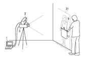
- FIG. 1 is a diagram showing an example of the configuration of an image processing system according to an embodiment of the present invention.
- the image processing system includes an image processing device 1, a camera 2, and a projector 3.
- the image processing apparatus 1 is a computer operated by a user, such as a personal computer or a portable terminal.
- the image processing apparatus 1 includes a processor 11, a storage unit 12, a communication unit 13, and an input / output unit 14.
- the processor 11 operates according to a program stored in the storage unit 12.
- the processor 11 controls the communication unit 13 and the input / output unit 14.
- the program may be provided through the Internet or the like, or may be provided by being stored in a computer-readable storage medium such as a DVD-ROM.
- the storage unit 12 includes a memory element such as a RAM or a flash memory, a hard disk drive, or the like.
- the storage unit 12 stores the program.
- the storage unit 12 stores information input from each unit and calculation results.
- the communication unit 13 realizes a function of communicating with other devices, and is configured by, for example, an integrated circuit or an antenna of a wired LAN or a wireless LAN. Based on the control of the processor 11, the communication unit 13 inputs information received from another device to the processor 11 or the storage unit 12 and transmits the information to the other device.
- the input / output unit 14 is a circuit that communicates with a display output device and other input / output devices. For example, data from an input device such as a graphic board that causes the display output device to output an image, a keyboard, a mouse, or a camera 2. It is comprised by the USB controller etc. which acquire.
- the input / output unit 14 outputs image data and the like to the display output device based on the control of the processor 11, and information from the operator (user), image data acquired by the camera 2, and the like from the input device. get.
- one of the display output devices connected to the input / output unit 14 is the projector 3, and the other is a display such as a liquid crystal display device (not shown).
- the camera 2 is a device that acquires a visible image and a distance image.
- the distance image is composed of pixels arranged two-dimensionally, and each pixel has information (distance) indicating how far an object in the direction of the pixel is from the camera 2.
- Each pixel included in the distance image may have the three-dimensional coordinates of the object in the direction of the pixel.
- the part of the camera 2 that acquires the distance image is for determining the distance based on the reflected infrared light emitted to the object, such as KINECT (registered trademark).
- a laser range finder, a camera projection system, a stereo camera, or the like may be used to acquire the distance.
- the projector 3 is a projection device that includes a light, a lens, and an element that controls the magnitude of output light for each pixel.
- the projector 3 projects the image indicated by the image data input from the input / output unit 14 onto a projection surface or the like at the tip of the lens.
- the size of the projected image increases as the projection surface with respect to the projector 3 is farther from the projector 3.
- a description will be given assuming that the calibration for the positional deviation is performed in advance.
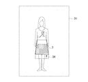
- FIG. 2 is a diagram showing an example of the arrangement of the camera 2, the projector 3, the projection surface, the object, and the projected image.
- the projection surface is a wall
- the object is bottoms 7
- the projected image is a human body image 8.
- the camera 2 captures a distance image or a visible image of the projection plane or object in the projection direction of the projector 3.
- the camera 2 includes a unit that irradiates infrared light for obtaining a distance image, and the longitudinal direction of the camera 2 is a direction orthogonal to the photographing direction.
- the distance image and the visible image captured by the camera 2 are sent to the image processing apparatus 1, and the projector 3 projects the human body image 8 on the wall. Further, the user adjusts the position of the bottoms 7 so that it is easy to determine the coordination while viewing the projected image, and is applied to the human body projected on the projection plane.
- the human body image 8 is projected onto the projection plane in a size that is adjusted to the actual size or the actual size so that the size can be compared with the bottoms 7.
- an object such as the human body image 8 projected on the projection plane is referred to as a first object
- an object held in front of the projection plane is referred to as a second object.
- the second object is not limited to the bottoms 7 and may be a tops or a curtain. When the second object is a curtain, a photograph of a room including a window may be used as a projected image.
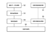
- FIG. 3 is a block diagram showing functions realized by the image processing apparatus 1.
- the image processing apparatus 1 includes a projection image analysis unit 51, an imaging data acquisition unit 52, a projection plane recognition unit 53, an object recognition unit 54, a projection image acquisition unit 55, and a projection control unit 56. Including. These functions are realized by the processor 11 executing a program stored in the storage unit 12 and controlling the input / output unit 14 and the like.
- the projection image acquisition unit 55, the object recognition unit 54, and the projection control unit 56 respectively correspond to the projection image acquisition unit, the object recognition unit, and the projection control unit of the claims of the present application.
- the projection image analysis unit 51 is realized centering on the processor 11, the storage unit 12, and the communication unit 13.
- the projection image analysis unit 51 acquires one or a plurality of projection images 31 that are candidates for an image to be projected on the projection plane, and projects an object such as a human body included in the projection image 31 to a full size. And information for selecting one of the plurality of projection images 31 are analyzed.
- the former information is, for example, the pixel length in the projection image corresponding to the height when the projection image 31 includes the human body image 8 as the object image, and the latter information is information such as the skin exposure mode. is there.
- One of the plurality of projection images 31 is processed and projected by the projector 3.
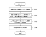
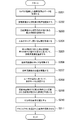
- FIG. 4 is a diagram illustrating an example of a processing flow of the projection image analysis unit 51.
- the projection image analysis unit 51 acquires image data of a plurality of projection images 31 (step S101).
- the projection image 31 is an image brought by the user and input to the image processing apparatus 1.
- the projection image analysis unit 51 receives image data stored in a non-volatile memory such as a flash memory via the input / output unit 14.
- the image data may be acquired via the communication unit 13 or may be acquired via the communication unit 13.
- the projection image analyzing unit 51 detects the positions of the upper and lower ends of the human body image included in the projection image 31 and the position of the head (step S102). Further, the projection image analyzing unit 51 detects the skin color ratio of the region corresponding to the upper body and the lower body (step S103). The projection image analysis unit 51 stores the detected information in the storage unit 12 (step S104).
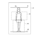
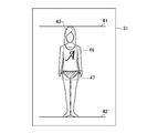
- FIG. 5 is a diagram illustrating an example of the projection image 31 and an example of a location to be analyzed. What is directly detected from the human body image included in the projection image 31 corresponds to the head region 43 of the human body and the upper end of the human head region 43 and is represented by the upper end line 41 of the human body. And the lower end of the human body represented by the lower end line 42 of the human body. The head region 43 is detected by a so-called face detection method. Further, the projection image analysis unit 51 may detect the upper end of the human body from the result of face detection, or may further search for and obtain an edge corresponding to the upper end of the head of the human body. The projection image analysis unit 51 may also acquire the lower end of the human body by searching for an edge corresponding to the shape of the human body. Moreover, you may make it acquire the upper end and lower end position input by the user's manual work.
- the skin detection region 44 corresponding to the upper body and the skin detection region 45 corresponding to the lower body shown in FIG. 5 are regions for obtaining a skin color ratio.
- the positions, shapes, etc. of these areas may be obtained from information on the head area 43 and the position of the lower end of the human body.
- the relationship between the head region 43 and the position of the lower end of the human body and the skin detection regions 44 and 45 may be statistically analyzed in advance and calculated using the statistical results. Further, the skin detection areas 44 and 45 may be calculated using the position of the upper end of the human body.
- FIG. 6 is a diagram illustrating another example of the projection image 31.
- the image shown in FIG. 6 is less exposed to human skin than the image shown in FIG. This difference is used to select an image to be projected by the projector, the details of which will be described later.
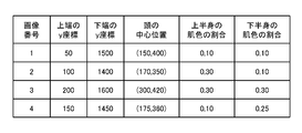
- FIG. 7 is a diagram illustrating an example of information detected from the projection image 31. This figure shows an example of data when four projection images 31 are input.
- information corresponding to the upper and lower ends of the human body the position of the head, the degree of exposure of the upper body, and the degree of exposure of the lower body
- an image number that is information for identifying the projection image 31, and the human body in the image 31 for projection an image number that is information for identifying the projection image 31, and the human body in the image 31 for projection .
- the coordinates indicating the center position of the head, the skin color ratio in the upper body skin detection area 44, and the skin color ratio in the lower body skin detection area 45 are detected.
- the image number 1 has a lower skin color ratio in the skin detection areas 44 and 45 of the upper body and the lower body than the other projection images 31 and corresponds to, for example, an image as shown in FIG.
- the skin color ratio in the skin detection areas 44 and 45 of the lower body is higher than that of the other projection images 31 and corresponds to a cool image such as a swimsuit.
- FIG. 8 is a diagram illustrating an example of a processing flow of the imaging data acquisition unit 52, the projection surface recognition unit 53, the object recognition unit 54, the projection image acquisition unit 55, and the projection control unit 56.
- the imaging data acquisition unit 52 is realized with the processor 11, the storage unit 12, and the input / output unit 14 as the center.
- the imaging data acquisition unit 52 acquires the distance image and visible image data of the projection plane captured by the camera 2 and the object in front of the projection plane (step S201).
- the projection plane recognition unit 53 is realized centering on the processor 11 and the storage unit 12.
- the projection plane recognition unit 53 recognizes the arrangement of the projection plane based on the distance image acquired by the shooting data acquisition unit 52 (step S202).
- a method for detecting the projection plane for example, three or more points may be extracted from the corners of the distance image, and the position and inclination of the projection plane may be recognized from their three-dimensional positions.
- an edge line whose depth changes abruptly from the distance image may be detected in advance, and points for recognizing the position and inclination of the projection plane may be extracted by excluding the area surrounded by the line.
- the processing of the projection plane recognition unit 53 may be omitted. Instead, for example, the user may manually measure the distance to the projection surface in advance and store the distance in the storage unit 12 in advance.
- the object recognition unit 54 is realized centering on the processor 11 and the storage unit 12.
- the object recognition unit 54 recognizes an object (second object) in front of the projection plane from the distance image (step S203). Precisely, the object recognition unit 54 recognizes the region 33 that is blocked by the second object in the image that the projector 3 projects toward the projection plane. More specifically, for example, the object recognizing unit 54 detects an edge line that is a place where the processing from the camera 2 suddenly changes in the distance image, and the area surrounded by the edge line is detected as the second object. Is recognized as a region 33 to be blocked.
- the object recognition unit 54 recognizes, as a region 33 that is blocked by the second object, a region that is in front of the projection surface recognized by the projection surface recognition unit 53 and has a distance from the projection surface that is greater than or equal to a certain distance. May be.
- the object recognition unit 54 uses the correction information stored in advance to detect the area shift due to the difference in the spatial position between the camera 2 and the projector 3. It may be corrected.
- the correction information is, for example, information indicating a shift in the xy direction between an image projected by the projector 3 and an image captured by the camera 2.
- the object recognition unit 54 calculates the area 33 that the second object blocks based on the spatial position of the second object with respect to the camera 2 and the spatial positional relationship between the camera 2 and the projector 3. become.
- the correction information indicating the spatial position of the second object with respect to the camera 2 can be calculated based on the image photographed by the camera 2.
- the object recognizing unit 54 can recognize the area 33 blocked by the second object before or after the projector 3 projects the projection image 31.
- the region 33 blocked by the second object may be a region in the projection image 31 that is blocked by the second object when the projection image 31 is projected.
- FIG. 9A is a diagram showing an example of the shape of an object in front of the projection plane.
- FIG. 9B is a diagram illustrating an example of a region 33 indicating an object in front of the projection plane recognized from the distance image.
- the distance image for the bottoms 7 as shown in FIG. 9A the distance from the camera 2 increases abruptly from the inside to the outside of the portion corresponding to the end of the bottoms 7, and the difference in the distance is more than a certain value.
- the projection plane is a plane and the direction thereof is detected, the distance from the projection plane can be obtained for each pixel constituting the distance image, and an area composed of pixels whose distance exceeds the threshold is set to the second area. You may isolate
- the object recognition unit 54 determines that the distance from the camera 2 out of the pixels of each image of the distance image is the bottoms 7 and the projection plane at the back of the bottoms 7. You may isolate
- the object recognition unit 54 may recognize the region 33 that is blocked by the second object using a visible image. For example, by periodically creating a state where the projection image 31 is not projected and detecting the edge of the second object from the visible image acquired in that state, the region 33 blocked by the second object can be recognized. Good.
- the projection image acquisition unit 55 is realized centering on the processor 11 and the storage unit 12.
- the projection image acquisition unit 55 selects one projection image 31 from among the plurality of projection images 31 input by the user and analyzed by the projection image analysis unit 51. More specifically, the projection image analysis unit 51 acquires information related to the size of the human body (step S204), and further determines the determination region determined according to the first object included in the projection image 31 as the second object.
- the projection image 31 is selected based on whether or not is hidden (step S205).
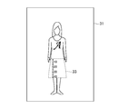
- FIG. 10 is a diagram illustrating an example of the relationship between the human body image and the determination areas 46 and 47.
- the determination area 46 is an area corresponding to the upper body excluding the human hand
- the determination area 47 is an area corresponding to the periphery of the hips in the lower body portion of the human body.
- the projection image acquisition unit 55 determines the degree of exposure (skin color ratio) in the skin detection area 44 corresponding to the upper body. Those that are smaller than the threshold value are candidates for the projection image 31. Thereby, it is possible to prevent an image of the upper body that is highly exposed from being accidentally projected.
- the second object hides (covers) the determination area 46 corresponding to the upper body
- the degree of exposure (skin color ratio) in the skin detection area 44 corresponding to the upper body is larger than the threshold value.
- the projection image 31 is a candidate. Thereby, it can suppress that the tops in the image 31 for projection protrude from the 2nd object (tops) applied to the upper body.
- the projection image acquisition unit 55 determines that the degree of exposure in the skin detection area 45 corresponding to the lower body is smaller than the threshold among the candidates. Obtained as a projection image 31. Thereby, it is possible to prevent an image with a high exposure of the lower body from being accidentally projected.
- a projection image 31 having a degree of exposure greater than the threshold in the skin detection area 45 corresponding to the lower body is acquired. Thereby, it is possible to prevent the bottoms in the projection image 31 from protruding from the second object (bottoms) applied to the lower body.
- the selection of the projection image 31 may not necessarily use the skin color ratio.
- the user may specify in advance whether or not the upper body exposure is large and the lower body exposure is large for each image, and may be selected based on the information.
- the size information acquired in step S204 is, for example, the height input by the user.
- the projection image acquisition unit 55 may predict the height after half a year from the child's age, height, and a known growth curve, and use the height in the following processing. In this way, when looking for clothes, you can easily check the coordinates taking into account the growth of the child's height.
- the projection image acquisition unit 55 determines the positions and sizes of the determination areas 46 and 47, the size information, the position of the head region 43 acquired from any of the projection images 31, and the position of the lower end of the human body. Obtained from the projection plane.
- the relationship between the position of the head region 43 and the position of the lower end of the human body and the positions of the determination regions 46 and 47 is statistically analyzed in advance, and the position and size of the determination regions 46 and 47 are determined based on the result and the position of the projection plane. What is necessary is just to calculate.
- the selection of the projection image 31 may be performed manually.
- a plurality of projection images 31 may be displayed on the display so that the user can select a projection image 31 projected by the projector 3 from among them.
- the projection control unit 56 is realized centering on the processor 11, the storage unit 12, and the input / output unit 14.
- the projection control unit 56 controls the projector 3 to project the projection image 31.
- the projection control unit 56 hides the area projected on the second object in the projection image 31 in which the size of the image of the first object projected onto the projection plane becomes the actual size.
- the projector 3 is controlled as described above.
- the projection control unit 56 adjusts the size of the projection image 31 (step S206). More specifically, using the information regarding the size of the second object acquired in step S204, the first object such as the human body image 8 included in the projection image 31 is a real size or similar size on the projection plane. The size of the projection image 31 is enlarged or reduced so as to be displayed. As described above, the projection control unit 56 may change the size of the first object to be projected from the actual size in consideration of the age of the child and the like. The enlargement / reduction ratio is calculated using information on the size of projecting the first object, the size of the projection screen, and the projection plane (distance to the projection plane, etc.).
- the projection plane is perpendicular to the projection direction of the projector 3, it is confirmed how many pixels of the projector 3 the line length corresponding to the height at the distance of the projection plane corresponds to the number of pixels and the human body
- the ratio of the number of pixels between the upper end line 41 and the human body lower end line 42 may be the enlargement / reduction ratio.
- the projection control unit 56 adjusts the position of the projection image 31 (step S207). This is a process for projecting the projection image 31 at the same position even if the position of the first object such as a person is different depending on the projection image 31. More specifically, the position of the projection image 31 is adjusted such that the position of the head projected on the projection plane overlaps regardless of which projection image 31 is selected.
- the projection control unit 56 may realize the size and position adjustment by converting the image data of the projection image 31 by software, or hardware such as an image processing circuit mounted on the graphic board. You may implement
- the projection control unit 56 determines the display mode based on the user's operation (step S208). More specifically, the projection control unit 56 performs a predetermined operation such as an operation of fixing the position of the first object for a certain period of time or an operation of shaking the first object for a while. In this case, the normal first mode is switched to the second mode for checking the correction amount of clothes and the like. The operation in the first mode and the second mode will be described below.
- the projection control unit 56 generates an image in which the region 33 projected onto the second object is hidden in the projection image 31 (step S209).
- This process differs slightly depending on the display mode.
- the first mode by generating an image in which the color of the region 33 corresponding to the second object as shown in FIG. 9B recognized by the object recognition unit 54 in the projection image 31 is replaced with a predetermined color.
- an image in which the region 33 projected onto the second object is hidden is generated.
- the projection image 31 is projected onto an area where the second object is not recognized at the timing designated by the user in the area 33 on the second object, and on the other second object. In this case, an image that does not project the portion of the projection image 31 is generated.
- the process of hiding the area is more specifically realized by, for example, painting the area in white.
- the color to be painted may be any color as long as there is no problem with the color of the second object onto which the color of the portion is projected, but white or gray is desirable.
- the projection control unit 56 adds an additional image (step S210).
- the additional image is, for example, a scale-like image that makes it possible to measure the length of the bottoms 7. More specifically, the projection control unit 56 adds a scale image extending from the upper end to the lower end of the recognized second object region 33 to the processed image in step S209.
- the 0 position of the scale is, for example, the upper end (in the case of bottoms 7) or the lower end. This process is executed in the first mode and may not be executed in the second mode, or this process may be omitted.
- FIG. 11 is a diagram illustrating an example of an image projected on the projector 3 and subjected to image processing in the first mode.
- a portion surrounded by a broken line in this figure is a portion hidden by the processing in step S209, and an image of a scale in the vertical direction is added as an additional image.
- the position of the scale image is adjusted so that the upper end portion of the bottoms 7 becomes zero.
- FIG. 12 is a diagram illustrating an example of a projected image and a second object in the first display mode.
- FIG. 13 is a diagram illustrating an example of a projected image and a second object in the second display mode.
- the projection control unit 56 scales from the upper end of the pre-movement area 34 blocked by the bottoms 7 at the timing instructed by the user to the lower end of the bottoms 7 (corresponding to the area 33) after the movement (current area). You may control it. Further, the projection control unit 56 may perform control so as to display a scale starting from the lower end of the bottoms 7 and the upper end of the bottoms 7 after the movement at a timing designated by the user so that the movement amount can be understood.
- 1 image processing device 2 camera, 3 projector, 7 bottoms, 8 human body image, 11 processor, 12 storage unit, 13 communication unit, 14 input / output unit, 31 projection image, 33 second object blocking area, 34 movement Front area, 41 Human body top line, 42 Human body bottom line, 43 Head area, 44, 45 Skin detection area, 46, 47 Determination area, 51 Projection image analysis section, 52 Imaging data acquisition section, 53 Projection plane recognition section, 54 object recognition unit, 55 image acquisition unit for projection, 56 projection control unit.
Landscapes
- Engineering & Computer Science (AREA)
- Physics & Mathematics (AREA)
- General Physics & Mathematics (AREA)
- Theoretical Computer Science (AREA)
- Signal Processing (AREA)
- Multimedia (AREA)
- Business, Economics & Management (AREA)
- Accounting & Taxation (AREA)
- Finance (AREA)
- Computer Vision & Pattern Recognition (AREA)
- Development Economics (AREA)
- Economics (AREA)
- Marketing (AREA)
- Strategic Management (AREA)
- General Business, Economics & Management (AREA)
- General Engineering & Computer Science (AREA)
- Human Computer Interaction (AREA)
- Projection Apparatus (AREA)
- Controls And Circuits For Display Device (AREA)
- Closed-Circuit Television Systems (AREA)
Priority Applications (3)
| Application Number | Priority Date | Filing Date | Title |
|---|---|---|---|
| US14/431,755 US10091474B2 (en) | 2012-09-28 | 2013-04-18 | Image processing device, image processing method, program and computer-readable storage medium |
| ES13842798T ES2738644T3 (es) | 2012-09-28 | 2013-04-18 | Dispositivo de procesamiento de imagen, método de procesamiento de imagen, programa, y soporte de almacenamiento legible por ordenador |
| EP13842798.4A EP2894851B1 (en) | 2012-09-28 | 2013-04-18 | Image processing device, image processing method, program, and computer-readable storage medium |
Applications Claiming Priority (2)
| Application Number | Priority Date | Filing Date | Title |
|---|---|---|---|
| JP2012-216568 | 2012-09-28 | ||
| JP2012216568A JP5791577B2 (ja) | 2012-09-28 | 2012-09-28 | 画像処理装置、画像表示方法、およびプログラム |
Publications (1)
| Publication Number | Publication Date |
|---|---|
| WO2014050186A1 true WO2014050186A1 (ja) | 2014-04-03 |
Family
ID=50387606
Family Applications (1)
| Application Number | Title | Priority Date | Filing Date |
|---|---|---|---|
| PCT/JP2013/061481 Ceased WO2014050186A1 (ja) | 2012-09-28 | 2013-04-18 | 画像処理装置、画像処理方法、プログラムおよびコンピュータ読取り可能な記憶媒体 |
Country Status (5)
| Country | Link |
|---|---|
| US (1) | US10091474B2 (enExample) |
| EP (1) | EP2894851B1 (enExample) |
| JP (1) | JP5791577B2 (enExample) |
| ES (1) | ES2738644T3 (enExample) |
| WO (1) | WO2014050186A1 (enExample) |
Cited By (2)
| Publication number | Priority date | Publication date | Assignee | Title |
|---|---|---|---|---|
| CN104052977A (zh) * | 2014-06-12 | 2014-09-17 | 海信集团有限公司 | 一种交互式图像投影方法和装置 |
| CN109104596A (zh) * | 2017-06-21 | 2018-12-28 | 中强光电股份有限公司 | 投影系统以及显示影像的校正方法 |
Families Citing this family (11)
| Publication number | Priority date | Publication date | Assignee | Title |
|---|---|---|---|---|
| CN106028010A (zh) * | 2016-06-17 | 2016-10-12 | 联想(北京)有限公司 | 一种显示控制方法及装置 |
| CN106060310A (zh) * | 2016-06-17 | 2016-10-26 | 联想(北京)有限公司 | 一种显示控制方法及装置 |
| JP6996114B2 (ja) * | 2017-05-29 | 2022-01-17 | セイコーエプソン株式会社 | プロジェクターおよびプロジェクターの制御方法 |
| CN108281880A (zh) * | 2018-02-27 | 2018-07-13 | 广东欧珀移动通信有限公司 | 控制方法、控制装置、终端、计算机设备和存储介质 |
| EP3564748A4 (en) | 2018-02-27 | 2020-04-08 | Guangdong Oppo Mobile Telecommunications Corp., Ltd. | CONTROL METHOD AND APPARATUS, TERMINAL, COMPUTER DEVICE, AND STORAGE MEDIUM |
| US10820650B2 (en) | 2018-02-27 | 2020-11-03 | Levi Strauss & Co. | Surface projection for apparel in an apparel design system |
| CN108805951B (zh) * | 2018-05-30 | 2022-07-19 | 重庆辉烨物联科技有限公司 | 一种投影图像处理方法、装置、终端和存储介质 |
| JP7342137B2 (ja) * | 2019-08-30 | 2023-09-11 | 株式会社Nttドコモ | 投射制御装置及び投射システム |
| KR102624995B1 (ko) * | 2021-03-26 | 2024-01-15 | 엔에이치엔클라우드 주식회사 | 딥러닝 기반의 복수의 의류 가상착용 방법 및 그 시스템 |
| JP7626104B2 (ja) * | 2022-06-20 | 2025-02-04 | トヨタ自動車株式会社 | システム及び端末装置 |
| US12361725B2 (en) * | 2023-03-22 | 2025-07-15 | GM Global Technology Operations LLC | Machine learning based HUD system with alerts for hidden bodies |
Citations (3)
| Publication number | Priority date | Publication date | Assignee | Title |
|---|---|---|---|---|
| JP2002297119A (ja) * | 2001-04-02 | 2002-10-11 | Canon Inc | 画像表示装置および画像表示システム |
| JP2004254145A (ja) * | 2003-02-21 | 2004-09-09 | Hitachi Ltd | 投射型表示装置 |
| JP2008148089A (ja) * | 2006-12-12 | 2008-06-26 | Nikon Corp | 投影装置およびカメラ |
Family Cites Families (19)
| Publication number | Priority date | Publication date | Assignee | Title |
|---|---|---|---|---|
| US5850222A (en) * | 1995-09-13 | 1998-12-15 | Pixel Dust, Inc. | Method and system for displaying a graphic image of a person modeling a garment |
| US7328119B1 (en) * | 2000-03-07 | 2008-02-05 | Pryor Timothy R | Diet and exercise planning and motivation including apparel purchases based on future appearance |
| US7953648B2 (en) * | 2001-11-26 | 2011-05-31 | Vock Curtis A | System and methods for generating virtual clothing experiences |
| JP2006145645A (ja) | 2004-11-17 | 2006-06-08 | Hitachi Ltd | 情報表示装置 |
| US8098330B2 (en) * | 2006-07-28 | 2012-01-17 | International Business Machines Corporation | Mapping of presentation material |
| US8068676B2 (en) * | 2007-11-07 | 2011-11-29 | Palo Alto Research Center Incorporated | Intelligent fashion exploration based on clothes recognition |
| US9241143B2 (en) * | 2008-01-29 | 2016-01-19 | At&T Intellectual Property I, L.P. | Output correction for visual projection devices |
| US8840470B2 (en) * | 2008-02-27 | 2014-09-23 | Sony Computer Entertainment America Llc | Methods for capturing depth data of a scene and applying computer actions |
| US8306265B2 (en) * | 2009-01-12 | 2012-11-06 | Eastman Kodak Company | Detection of animate or inanimate objects |
| GB2473503B (en) | 2009-09-15 | 2015-02-11 | Metail Ltd | System and method for image processing |
| JP5454325B2 (ja) * | 2009-11-18 | 2014-03-26 | セイコーエプソン株式会社 | 画像形成装置 |
| CN102193287B (zh) * | 2010-03-11 | 2013-03-20 | 宏碁股份有限公司 | 投影方法与投影系统 |
| US20110234481A1 (en) | 2010-03-26 | 2011-09-29 | Sagi Katz | Enhancing presentations using depth sensing cameras |
| JP2011237907A (ja) * | 2010-05-07 | 2011-11-24 | Sony Corp | 画像処理装置、画像処理方法、およびプログラム |
| US8976230B1 (en) * | 2010-06-28 | 2015-03-10 | Vlad Vendrow | User interface and methods to adapt images for approximating torso dimensions to simulate the appearance of various states of dress |
| GB201102794D0 (en) * | 2011-02-17 | 2011-03-30 | Metail Ltd | Online retail system |
| US8782565B2 (en) | 2012-01-12 | 2014-07-15 | Cisco Technology, Inc. | System for selecting objects on display |
| JP5728406B2 (ja) * | 2012-01-30 | 2015-06-03 | 楽天株式会社 | 衣服画像処理システム、衣服画像処理方法、プログラム |
| US9147207B2 (en) * | 2012-07-09 | 2015-09-29 | Stylewhile Oy | System and method for generating image data for on-line shopping |
-
2012
- 2012-09-28 JP JP2012216568A patent/JP5791577B2/ja active Active
-
2013
- 2013-04-18 US US14/431,755 patent/US10091474B2/en active Active
- 2013-04-18 EP EP13842798.4A patent/EP2894851B1/en active Active
- 2013-04-18 ES ES13842798T patent/ES2738644T3/es active Active
- 2013-04-18 WO PCT/JP2013/061481 patent/WO2014050186A1/ja not_active Ceased
Patent Citations (3)
| Publication number | Priority date | Publication date | Assignee | Title |
|---|---|---|---|---|
| JP2002297119A (ja) * | 2001-04-02 | 2002-10-11 | Canon Inc | 画像表示装置および画像表示システム |
| JP2004254145A (ja) * | 2003-02-21 | 2004-09-09 | Hitachi Ltd | 投射型表示装置 |
| JP2008148089A (ja) * | 2006-12-12 | 2008-06-26 | Nikon Corp | 投影装置およびカメラ |
Non-Patent Citations (2)
| Title |
|---|
| "Outdoor media becomes a shoe store", INTERNET, 16 September 2012 (2012-09-16), Retrieved from the Internet <URL:http://www.adverblog.com/2012/06/03/outdoor-media-becomes -a-shoe-store> |
| See also references of EP2894851A4 |
Cited By (2)
| Publication number | Priority date | Publication date | Assignee | Title |
|---|---|---|---|---|
| CN104052977A (zh) * | 2014-06-12 | 2014-09-17 | 海信集团有限公司 | 一种交互式图像投影方法和装置 |
| CN109104596A (zh) * | 2017-06-21 | 2018-12-28 | 中强光电股份有限公司 | 投影系统以及显示影像的校正方法 |
Also Published As
| Publication number | Publication date |
|---|---|
| ES2738644T3 (es) | 2020-01-24 |
| EP2894851A1 (en) | 2015-07-15 |
| EP2894851B1 (en) | 2019-06-05 |
| US20150244997A1 (en) | 2015-08-27 |
| JP5791577B2 (ja) | 2015-10-07 |
| JP2014072656A (ja) | 2014-04-21 |
| US10091474B2 (en) | 2018-10-02 |
| EP2894851A4 (en) | 2016-05-25 |
Similar Documents
| Publication | Publication Date | Title |
|---|---|---|
| JP5791577B2 (ja) | 画像処理装置、画像表示方法、およびプログラム | |
| JP5791812B2 (ja) | 衣服画像処理装置、衣服画像表示方法、およびプログラム | |
| EP2745504B1 (en) | Image projector, image processing method, computer program and recording medium | |
| KR101198727B1 (ko) | 화상투영장치 및 그 제어 방법 | |
| US12203744B2 (en) | Detection device, detection system, detection method, and storage medium | |
| JP5834615B2 (ja) | プロジェクタ、その制御方法、そのプログラム、及び、そのプログラムを記録した記録媒体 | |
| KR102111935B1 (ko) | 표시 제어장치, 표시 제어방법 및 프로그램 | |
| JP2015510112A (ja) | 仮想定規 | |
| WO2018111915A1 (en) | Foot measuring and sizing application | |
| JP6027581B2 (ja) | 画像合成装置,画像合成方法,画像合成装置の制御プログラムおよびそのプログラムを格納した記録媒体 | |
| JP2014106732A (ja) | 情報処理装置および情報処理方法 | |
| JP2013235373A5 (enExample) | ||
| JP2014238731A (ja) | 画像処理装置、画像処理システム、および画像処理方法 | |
| JP2013196355A (ja) | 物体測定装置、及び物体測定方法 | |
| KR101703013B1 (ko) | 3차원 스캐너 및 스캐닝 방법 | |
| KR20170027266A (ko) | 영상 촬영 장치 및 그 동작 방법 | |
| JP2017194301A (ja) | 顔形状測定装置及び方法 | |
| JP2016085380A (ja) | 制御装置、制御方法、及び、プログラム | |
| JP6406044B2 (ja) | カメラ校正ユニット、カメラ校正方法、およびカメラ校正プログラム | |
| JP2020017265A5 (enExample) | ||
| JP6547012B2 (ja) | 生体情報解析装置及びその基礎化粧解析方法 | |
| JP2019045989A (ja) | 情報処理装置、情報処理方法およびコンピュータプログラム | |
| US9843715B2 (en) | Photographic apparatus, stroboscopic image prediction method, and a non-transitory computer readable storage medium storing stroboscopic image prediction program | |
| JP6390163B2 (ja) | 情報処理装置、情報処理方法およびプログラム | |
| WO2020240989A1 (ja) | 撮像装置、撮像制御方法および撮像制御プログラム |
Legal Events
| Date | Code | Title | Description |
|---|---|---|---|
| 121 | Ep: the epo has been informed by wipo that ep was designated in this application |
Ref document number: 13842798 Country of ref document: EP Kind code of ref document: A1 |
|
| WWE | Wipo information: entry into national phase |
Ref document number: 14431755 Country of ref document: US |
|
| NENP | Non-entry into the national phase |
Ref country code: DE |
|
| WWE | Wipo information: entry into national phase |
Ref document number: 2013842798 Country of ref document: EP |