WO2014049718A1 - 管理装置及び管理方法 - Google Patents
管理装置及び管理方法 Download PDFInfo
- Publication number
- WO2014049718A1 WO2014049718A1 PCT/JP2012/074702 JP2012074702W WO2014049718A1 WO 2014049718 A1 WO2014049718 A1 WO 2014049718A1 JP 2012074702 W JP2012074702 W JP 2012074702W WO 2014049718 A1 WO2014049718 A1 WO 2014049718A1
- Authority
- WO
- WIPO (PCT)
- Prior art keywords
- storage device
- path
- access path
- logical volume
- port
- Prior art date
Links
Images


Classifications
-
- G—PHYSICS
- G06—COMPUTING; CALCULATING OR COUNTING
- G06F—ELECTRIC DIGITAL DATA PROCESSING
- G06F11/00—Error detection; Error correction; Monitoring
- G06F11/07—Responding to the occurrence of a fault, e.g. fault tolerance
- G06F11/16—Error detection or correction of the data by redundancy in hardware
- G06F11/20—Error detection or correction of the data by redundancy in hardware using active fault-masking, e.g. by switching out faulty elements or by switching in spare elements
-
- G—PHYSICS
- G06—COMPUTING; CALCULATING OR COUNTING
- G06F—ELECTRIC DIGITAL DATA PROCESSING
- G06F3/00—Input arrangements for transferring data to be processed into a form capable of being handled by the computer; Output arrangements for transferring data from processing unit to output unit, e.g. interface arrangements
- G06F3/06—Digital input from, or digital output to, record carriers, e.g. RAID, emulated record carriers or networked record carriers
- G06F3/0601—Interfaces specially adapted for storage systems
- G06F3/0628—Interfaces specially adapted for storage systems making use of a particular technique
- G06F3/0662—Virtualisation aspects
- G06F3/0664—Virtualisation aspects at device level, e.g. emulation of a storage device or system
-
- G—PHYSICS
- G06—COMPUTING; CALCULATING OR COUNTING
- G06F—ELECTRIC DIGITAL DATA PROCESSING
- G06F13/00—Interconnection of, or transfer of information or other signals between, memories, input/output devices or central processing units
- G06F13/10—Program control for peripheral devices
-
- G—PHYSICS
- G06—COMPUTING; CALCULATING OR COUNTING
- G06F—ELECTRIC DIGITAL DATA PROCESSING
- G06F3/00—Input arrangements for transferring data to be processed into a form capable of being handled by the computer; Output arrangements for transferring data from processing unit to output unit, e.g. interface arrangements
- G06F3/06—Digital input from, or digital output to, record carriers, e.g. RAID, emulated record carriers or networked record carriers
- G06F3/0601—Interfaces specially adapted for storage systems
- G06F3/0602—Interfaces specially adapted for storage systems specifically adapted to achieve a particular effect
- G06F3/0608—Saving storage space on storage systems
-
- G—PHYSICS
- G06—COMPUTING; CALCULATING OR COUNTING
- G06F—ELECTRIC DIGITAL DATA PROCESSING
- G06F3/00—Input arrangements for transferring data to be processed into a form capable of being handled by the computer; Output arrangements for transferring data from processing unit to output unit, e.g. interface arrangements
- G06F3/06—Digital input from, or digital output to, record carriers, e.g. RAID, emulated record carriers or networked record carriers
- G06F3/0601—Interfaces specially adapted for storage systems
- G06F3/0602—Interfaces specially adapted for storage systems specifically adapted to achieve a particular effect
- G06F3/0614—Improving the reliability of storage systems
- G06F3/0617—Improving the reliability of storage systems in relation to availability
-
- G—PHYSICS
- G06—COMPUTING; CALCULATING OR COUNTING
- G06F—ELECTRIC DIGITAL DATA PROCESSING
- G06F3/00—Input arrangements for transferring data to be processed into a form capable of being handled by the computer; Output arrangements for transferring data from processing unit to output unit, e.g. interface arrangements
- G06F3/06—Digital input from, or digital output to, record carriers, e.g. RAID, emulated record carriers or networked record carriers
- G06F3/0601—Interfaces specially adapted for storage systems
- G06F3/0628—Interfaces specially adapted for storage systems making use of a particular technique
- G06F3/0629—Configuration or reconfiguration of storage systems
- G06F3/0635—Configuration or reconfiguration of storage systems by changing the path, e.g. traffic rerouting, path reconfiguration
-
- G—PHYSICS
- G06—COMPUTING; CALCULATING OR COUNTING
- G06F—ELECTRIC DIGITAL DATA PROCESSING
- G06F3/00—Input arrangements for transferring data to be processed into a form capable of being handled by the computer; Output arrangements for transferring data from processing unit to output unit, e.g. interface arrangements
- G06F3/06—Digital input from, or digital output to, record carriers, e.g. RAID, emulated record carriers or networked record carriers
- G06F3/0601—Interfaces specially adapted for storage systems
- G06F3/0628—Interfaces specially adapted for storage systems making use of a particular technique
- G06F3/0662—Virtualisation aspects
- G06F3/0665—Virtualisation aspects at area level, e.g. provisioning of virtual or logical volumes
-
- G—PHYSICS
- G06—COMPUTING; CALCULATING OR COUNTING
- G06F—ELECTRIC DIGITAL DATA PROCESSING
- G06F3/00—Input arrangements for transferring data to be processed into a form capable of being handled by the computer; Output arrangements for transferring data from processing unit to output unit, e.g. interface arrangements
- G06F3/06—Digital input from, or digital output to, record carriers, e.g. RAID, emulated record carriers or networked record carriers
- G06F3/0601—Interfaces specially adapted for storage systems
- G06F3/0668—Interfaces specially adapted for storage systems adopting a particular infrastructure
- G06F3/067—Distributed or networked storage systems, e.g. storage area networks [SAN], network attached storage [NAS]
Definitions
- the present invention relates to a management apparatus and a management method, manages storage areas provided by a plurality of storage apparatuses as a logical pool across the plurality of storage apparatuses, and provides a virtual volume associated with the logical pool to a host computer.
- the present invention is suitable for application to a management computer that performs performance management of a computer system that dynamically allocates storage areas from a logical pool to a virtual volume.
- Patent Document 1 a virtual logical volume (hereinafter referred to as a virtual logical volume) is applied to a host computer, and the virtual logical volume is assigned to the virtual logical volume according to the data write status from the host computer to the virtual logical volume.
- a thin provisioning technique that dynamically allocates a physical storage area from a storage apparatus is disclosed.
- a storage apparatus that has received an I / O request determines whether the I / O request is a request for a storage area in the own storage apparatus, and a storage area in another storage apparatus.
- a technology for transferring the I / O request to the other storage device is disclosed.
- Patent Document 3 discloses a technology that enables pools in different storage apparatuses to be integrated by incorporating a storage area of a pool existing in another storage apparatus into a storage area used by a pool constructed in the storage apparatus. Is disclosed.
- Patent Document 4 discloses a technique for diagnosing whether or not the access path from the host computer to the storage device is optimal. According to this technique, it is possible to display an optimum access path from the host computer to the storage apparatus, or to switch the path from the host computer to the storage apparatus to the optimum access path.
- the storage area of one virtual logical volume is distributed and arranged in a plurality of storage devices, and the I / O request from the host computer is stored in its own storage.
- the I / O request from the host computer is stored in its own storage.
- an optimum path that takes into account I / O requests and data transfer between storage devices is identified as the access path used when the host computer accesses the virtual logical volume, and the identified path is used. If the access path can be changed, it is considered that the access speed can be improved and the access performance from the host computer in the computer system to the data stored in the virtual logical volume can be improved.
- the present invention has been made in view of the above points, and intends to propose a management apparatus and a management method capable of improving data access performance.
- a plurality of storage devices are connected to each other, and a storage area provided by each of the first storage device and the second storage device included in the plurality of storage devices is stored in a plurality of storage devices.
- Managed as a logical pool across devices provides a virtual logical volume associated with the logical pool to a host computer, and dynamically stores from the logical volume to the virtual logical volume according to the usage status of the virtual logical volume
- the first storage Access to the second storage device via a second path connecting between the first storage device and the second storage device if the second storage device is present, It is determined whether or not the ratio of the access amount using the second path exceeds a predetermined ratio, and when the ratio of the access amount exceeds the predetermined ratio, the virtual logic is sent from the host computer.
- An access path diagnosis unit that determines that there is a problem with the access path to the volume, and a third path that connects between the host computer and the second storage device when it is determined that there is a problem with the access path
- the change destination path specifying unit for specifying the access path change destination and the third path specified by the change destination path specifying unit as the first path. Te, it was provided and an access path changing unit for executing a predetermined control processing for changing the part of the access path from the host computer to said virtual logical volume.
- a plurality of storage devices are connected to each other, and a storage area provided by each of the first storage device and the second storage device included in the plurality of storage devices is straddled across the plurality of storage devices.
- a computer system that provides a virtual logical volume associated with the logical pool to a host computer and dynamically allocates a storage area from the logical volume to the virtual logical volume according to the usage status of the virtual logical volume The host computer is connected to the first storage device via a first path and connected to the virtual logical volume via the first path.
- the access target data is in the first storage device, the first Accessing a storage device, and if there is in the second storage device, accessing the second storage device via a second path connecting the first storage device and the second storage device;
- the access path can be changed so that the data transfer between the storage apparatuses can be further reduced. It is possible to effectively prevent a decrease in the access speed to the virtual logical volume.
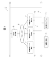
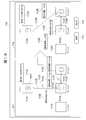
- reference numeral 1 denotes a computer system according to this embodiment as a whole.
- the computer system 1 includes a host computer 2, a plurality of physical storage devices 3, a management computer 4, and a management client 5.
- the host computer 2 and the plurality of physical storage devices 3 are connected via a host communication network 6, and the physical storage devices 3 are connected to each other via an inter-device communication network 7.
- the host computer 2, the plurality of physical storage devices 3, the management computer 4, and the management client 5 are connected via a management network 8.
- the host communication network 6 is composed of a SAN (Storage Area Network).
- the host computer 2 sends and receives various commands such as I / O requests and various data to the physical storage device 3 via the host communication network 6.
- the inter-device communication network 7 is also composed of a SAN. Each physical storage device 3 transfers an I / O request from the host computer 2 to another physical storage device 3 via this inter-device communication network 7, or sends and receives data between the physical storage devices 3. To do.
- the host communication network 6 and the inter-device communication network 7 may be separate networks as shown in FIG. 1 or the same network.
- the management network 8 is composed of a LAN (Local Area Network).
- the management computer 4 collects information from the host computer 2 and each physical storage device 3 via the management network 8 and performs various settings for the host computer 2 and each physical storage device 3.
- the management computer 4 communicates with the management client 5 via the management network 8.
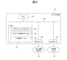
- FIG. 2 shows a schematic configuration of the host computer 2.
- the host computer 2 includes a CPU (Central Processing Unit) 10 and a memory 11, one or a plurality of SAN ports 12 and a LAN port 13, and an internal connection between the CPU 10, the memory 11, the SAN port 12 and the LAN port 13. And a bus 14.
- CPU Central Processing Unit
- the CPU 10 is a processor that controls operation of the entire host computer 2.
- the memory 11 is used to hold various programs and various data.
- the memory 11 is used to manage one or more application programs 15, a multipath management program 16 that manages a plurality of paths connecting the host computer 2 and each physical storage device 3, and such paths.
- a path management table 17 is stored.
- the SAN port 12 is a port for the host communication network 6 and is given a unique network address (for example, WWN (World Wide Name)) on the host communication network 6.
- the LAN port 13 is a port for the management network 8 and is given a unique network address (for example, an IP (Internet Protocol address) address) on the management network 8.
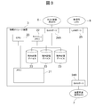
- FIG. 3 shows the internal configuration of the physical storage device 3.
- the physical storage apparatus 3 includes a CPU 20, a memory 21, a cache memory 22, one or a plurality of physical storage devices 23, first and second SAN ports 24 A and 24 B, and a LAN port 25, which are connected via an internal bus 26. Are connected to each other.
- the CPU 20 is a processor that controls the operation of the entire physical storage device 3, reads a program stored in the physical storage device 23 into the memory 21, and executes the read program as necessary.
- the memory 21 is used not only for storing various programs read from the physical storage device 23 but also as a work memory for the CPU 20.
- the cache memory 22 is mainly used for temporarily storing data to be read from and written to the physical storage device 23.
- the first SAN port 24A is a port for the host communication network 6, and the second SAN port 24B is a port for the inter-device communication network 7. Further, the LAN port 25 is a port for the management network 8. These ports are given unique identifiers (for example, WWN and IP address) in each network.
- the first SAN port 24A will be referred to as a front end port 24A and the second SAN port will be referred to as a back end port 24B as appropriate.
- the physical storage device 23 is composed of an expensive disk device such as a SCSI (Small Computer System Interface) disk or an inexpensive disk device such as a SATA (Serial AT Attachment) disk or an optical disk.
- SCSI Serial Computer System Interface
- SATA Serial AT Attachment
- One or a plurality of logical volumes VOL are set on the storage areas provided by these physical storage devices 23, respectively.
- the physical storage device 23 can be replaced with a RAID (Redundant Arrays of Inexpensive Disks) group.
- a RAID group refers to an aggregate of a plurality of storage devices that have the same physical characteristics such as disk rotation speed.
- the CPU 20 manages a storage area provided by a plurality of physical storage devices 23 constituting one RAID group as a storage area provided by one logical storage device, and one or a plurality of logical areas are stored on the storage area. Set the volume VOL.
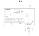
- FIG. 4 shows a schematic configuration of the management computer 4.
- the management computer 4 includes a CPU 30, a memory 31, and a LAN port 32.
- the CPU 30 is a processor that controls operation of the entire management computer 4.
- the memory 31 is mainly used for storing various programs and various data.
- a control program 40 and control data 41, which will be described later, are also stored and held in the memory 31.
- the CPU 30 executes the control program 40 stored in the memory 31, various processes as described below as the management computer 4 as a whole are executed.
- the LAN port 32 is a port for the management network 8 and is given a unique network address (for example, an IP address) on the management network 8.
- the management client 5 is a computer device used by a system administrator, and is composed of, for example, a personal computer, a workstation, or a main frame.
- the management client 5 includes a display device composed of a liquid crystal panel and an input device composed of a mouse and / or a keyboard.
- FIG. 5 shows the logical configuration of the computer system 1.
- one virtual storage device VST is constructed by a plurality of physical storage devices 3 connected via an inter-device communication network 7.
- a logical volume VOL is created in the storage area provided by the physical storage device 23 in each physical storage device 3, and one logical volume VOL spans between the physical storage devices 3. It is managed as a logical pool (device crossing pool) PL.
- the virtual storage apparatus VST one or a plurality of virtual logical volumes VVOL straddling a plurality of physical storage apparatuses 3 constituting the virtual storage apparatus VST are created, and the virtual logical volume VVOL is provided to the host computer 2.
- the host computer 2 recognizes a plurality of physical storage devices 3 connected via the inter-device communication network 7 as one virtual storage device VST, and the virtual logical volume VVOL is a logical volume provided by the virtual storage device VST. recognize. At this time, the host computer 2 selects any one path as an access path from among a plurality of paths set between the plurality of physical storage apparatuses 3 constituting the virtual storage apparatus VST. Thereafter, the host computer 2 sends and receives read requests and write requests to the virtual logical volume VVOL, and data transmission and reception for these read requests and write requests to and from a specific physical storage device 3 via this access path. Do.
- a logical storage area (hereinafter referred to as “this”) from any of the logical volumes VOL constituting the cross-device pool PL. Is called a logical page).
- the logical page LP is associated with a physical storage area (hereinafter referred to as a physical page) PP having a predetermined size in the physical storage apparatus 3 in which the logical volume VOL exists.
- the physical page PP is allocated to the virtual logical volume VVOL by the required number according to the size of the write target data, and the target data is stored in the physical page PP.
- the target data is stored in the physical page PP.
- the write request is issued from the physical storage device 3 to which the access path is connected.
- the page PP is transferred to the physical storage device 3 to which the page PP is allocated via the inter-device communication network 7 and stored in the physical page PP.
- the read request is transmitted from the physical storage device 3 directly connected to the host computer 2 to the inter-device communication. Is transferred to the physical storage device 3 in which the target data exists via the network 7.
- the read target data read from the physical storage device 3 is transmitted to the physical storage device 3 directly connected to the host computer 2 via the inter-device communication network 7, and the data Data is transmitted to the host computer 2 that issued the read request via the above-described access path.
- the management computer 4 moves the data with high access frequency to the physical storage device 3 to which the access path to the host computer 2 is connected, and transfers the data with low access frequency to the host.
- a hierarchical data management function for controlling each physical storage device that configures the virtual storage device VST is mounted so that the access path to the computer 2 is moved to a physical storage device 3 that is not connected.
- the management computer 4 constantly monitors the access frequency to the data held by each physical storage device 3, and the access frequency to the data held by the physical storage device 3 to which the access path to the host computer 2 is not connected. Is greater than or equal to a predetermined threshold value, the physical storage device 3 is controlled to move the data to the physical storage device 3 to which the access path between the host computer 2 and the host computer 2 is connected. When the access frequency to the data held by the physical storage device 3 to which no access path is connected is less than a predetermined threshold, the host computer 2 and the host computer 2 are moved to move the data to another physical storage device 3. The physical storage device 3 to which the access path is connected is controlled.
- the response performance to the I / O request from the host computer 2 can be improved while reducing the occurrence of data transfer between the physical storage devices 3.
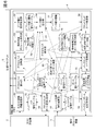
- FIG. 6 shows a detailed configuration of the above-described control program 40 (FIG. 4) and control data 41 (FIG. 4) stored in the memory 31 of the management computer 4.
- each rectangle represents a program module constituting the control program 40
- each columnar shape represents a management table or information constituting the control data 41.
- control program 40 includes a host computer information collection unit 50, a storage device information collection unit 51, a data bias threshold setting unit 52, an exclusion target volume designation unit 53, a data bias calculation unit 54, a remaining balance.
- Band corrected port information creation unit 55 front end port search unit 56, back end port pair search unit 57, front end port change control unit 58, back end port change control unit 59, access path diagnosis unit 60, access path search unit 61 and an access path display unit 62.
- the control data 41 includes a path management table 70, a virtual logical volume management table 71, a page management table 72, a port management table 73, a port pair management table 74, a data bias threshold management table 75, an exclusion target volume management table 76, and data bias information. 77, remaining bandwidth corrected port information 78, changeable front end port information 79, change target front end port information 80, and change target back end port pair information 81.
- the host computer information collection unit 50 is activated at a predetermined timing (for example, periodically by a timer according to the scheduling setting) or is activated by a request from the management client 5, and the host computer 2 and each physical storage device Information about paths between the three is collected from the host computer 2 and the collected information is stored in the path management table 70.
- the storage device information collection unit 51 is activated at a predetermined timing (for example, periodically by a timer according to a scheduling setting) or is activated by a request from the management client 5, and each virtual storage device 3 receives a virtual Information on each virtual logical volume VVOL created in the storage apparatus VST (hereinafter referred to as virtual logical volume information) is collected, and the collected virtual logical volume information is stored in the virtual logical volume management table 71.
- the storage device information collection unit 51 also receives information on each logical page LP in each virtual logical volume VVOL (hereinafter referred to as page information) from each physical storage device 3 and information on the port of the physical storage device 3. (Hereinafter referred to as port information) and information related to paths between physical storage devices 3 (hereinafter referred to as port pair information) are collected.
- the storage device information collection unit 51 stores the collected page information in the page management table 72, stores the port information in the port management table 73, and stores the port pair information in the port pair management table 74.
- the data bias threshold value setting unit 52 acquires the data bias threshold value and the port free bandwidth threshold value set by the system administrator using the management client 5 from the management client 5, and the acquired data bias threshold value and the port free bandwidth threshold value are obtained. Stored in the data bias threshold management table 75.
- the “data bias threshold” is the amount of data stored in the physical storage device 3 directly connected to the host computer 2 via the access path with respect to the total amount of data stored in one virtual logical volume VVOL. Refers to the lower limit of the percentage. As will be described later, when the ratio of the amount of data stored in the physical storage device 3 directly connected to the host computer 2 via the access path is less than this data bias threshold, it is stored in the corresponding virtual logical volume VVOL. Since the stored data is considered to be distributed to physical storage devices 3 other than the physical storage device 3, it is determined that there is a problem in the access path from the currently set host computer 2 to the virtual logical volume VVOL. .
- the “port free bandwidth threshold” refers to the lower limit value of the free bandwidth of each port in the physical storage device 3. As will be described later, when the remaining bandwidth of the port of the physical storage device 3 is less than this port free bandwidth threshold, it is determined that there is a problem in the access path from the currently set host computer 2 to the virtual logical volume VVOL.
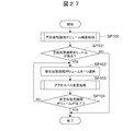
- the exclusion target volume designating unit 53 is a virtual logical volume to be excluded from access path diagnosis processing (FIG. 20) and access path automatic update processing (FIG. 27) described later, which is set by the system administrator using the management client 5.
- An identifier (virtual logical volume ID) of the VVOL (hereinafter referred to as an exclusion target volume) is acquired from the management client 5, and the acquired virtual logical volume ID of the exclusion target volume VVOL is stored in the exclusion target volume management table 76.
- the data bias calculation unit 54 stores each piece of data stored in the target virtual logical volume VVOL. A biased state of distribution to the physical storage device 3 is detected, and data bias information 77 representing the biased state is generated.
- the remaining bandwidth corrected port information creation unit 55 corrects the remaining bandwidth indicating the remaining bandwidth of each port of each physical storage device 3 when there is no data input / output to the target virtual logical volume VVOL at that time. Port information 78 is generated.
- the front end port search unit 56 includes the host computer 2 and the virtual storage device VST among the front end ports 24A (FIG. 3) of each physical storage device 3.
- a front end port 24A having a remaining bandwidth that can be the access path change destination is searched, and changeable front end port information 79 including a list of such front end ports 24A is generated.
- the back-end port pair search unit 57 selects another physical among the back-end ports 24B (FIG. 3) of each physical storage device 3.
- a set of back-end ports 24B (hereinafter referred to as a back-end port pair) connected to a path that can be a change destination of a path (access path) used for communication with the storage apparatus 3 is searched, and such back
- the change target back-end port pair information 81 including a list of end port pairs is generated.
- the front end port change control unit 58 uses the access path display unit 62 to indicate the connection destination of the access path used when the host computer 2 accesses the virtual logical volume VVOL based on the changeable front end port information 79 described later.
- the host computer 2 is controlled to change to the front end port 24A designated by the access path display unit 62 in the designated physical storage device 3, and the path management table 70 is updated accordingly.
- the back-end port change control unit 59 accesses the back-end port 24B used when each physical storage device 3 communicates with another physical storage device 3 based on the change-target back-end port pair information 81 described later. Each physical storage device 3 is controlled to change to the back-end port 24B designated by the path display unit 62.
- the access path diagnosis unit 60 is activated by a request from the management client 5 according to the operation of the system administrator, and based on the virtual logical volume management table 71, the data bias threshold information 75, and the exclusion target volume management table 76, at that time Whether there is a problem in the access path from the target host computer (hereinafter referred to as the target host computer) 2 to the target virtual logical volume (hereinafter referred to as the target virtual logical volume) VVOL Diagnose. Then, the access path diagnosis unit 60 displays the diagnosis result on the display device of the management client 5 as an access path diagnosis result screen 90 or an access path diagnosis result detail screen 100 described later.
- the access path search unit 61 is activated in response to a request from the management client 5 according to the operation of the system administrator, and the data stored in the target virtual logical volume VVOL is transferred to each physical storage device 3 according to the degree of bias.
- the computer 2 specifies the path to be changed to the access path used when accessing the data stored in the target virtual logical volume VVOL, and notifies the access path display unit 62 of the specified result.
- the access path display unit 62 specifies the access path specified when the target host computer 2 accesses the target virtual logical volume VVOL specified by the access path search unit 61.
- the path to be changed is displayed on the management client 5 as an access path change screen 110 described later.
- the access path display unit 62 controls the front-end port change control unit 58 and the back-end port change control unit 59 in accordance with an operation input by the system administrator using the access path change screen 110, so that the target host The access path when the computer 2 accesses the data stored in the target virtual logical volume VVOL is changed to the path displayed on the access path change screen 110 (that is, the path specified by the access path search unit 61).
- the path management table 70 is a table used for managing all paths that can be used when the host computer 2 accesses the virtual logical volume VVOL in the virtual storage apparatus VST, as shown in FIG. Are composed of a virtual logical volume ID column 70A, a host computer ID column 70B, a host computer port ID column 70C, a physical storage device ID column 70D, a physical storage device port ID column 70E, a LUN column 70F, and an access path information column 70G. .
- the virtual logical volume ID column 70A stores the virtual logical volume ID assigned to each virtual logical volume VVOL set in the virtual storage device VST, and the host computer ID column 70B stores the corresponding virtual logical volume. Stores the identifier (host computer ID) of the host computer 2 that uses the VVOL.
- the host computer port ID column 70C stores the identifier (host computer port ID) of the port on the host computer 2 side to which the path corresponding to the entry (row) is connected.
- the physical storage device ID column 70D stores the identifier (physical storage device ID) of the physical storage device 3 to which the path corresponding to the entry is connected
- the physical storage device port ID column 70E stores the physical storage device.
- 3 stores the port ID of the front end port 24A (FIG. 3) in the physical storage apparatus 3 to which the path in FIG. 3 is connected.
- the LUN column 70F stores the identification number (LUN: Logical Unit Number) of the corresponding virtual logical volume VVOL recognized by the corresponding host computer 2, and the access path information column 70G contains the path corresponding to the entry.
- Information indicating whether the corresponding host computer 2 is an access path for accessing the corresponding virtual logical volume VVOL (hereinafter referred to as access path information) is stored.
- the access path information column 70G stores “true” when the corresponding path is an access path, and stores “false” when the corresponding path is not an access path.
- the virtual logical volume management table 71 is a table used for managing the virtual logical volume VVOL created in the virtual storage apparatus VST. As shown in FIG. 8, the virtual logical volume ID column 71A, the host computer ID It consists of a column 71B, a transfer amount column 71C and a capacity column 71D.
- the virtual logical volume ID column 71A stores the volume IDs of all virtual logical volumes VVOL created in the virtual storage apparatus VST, and the corresponding virtual logical volume VVOL can be used in the host computer ID column 71B.
- the host computer ID of the host computer 2 is stored.
- the transfer amount column 71C stores the data amount per unit time (for example, 1 second) of data input to and output from the corresponding virtual logical volume VVOL (hereinafter referred to as transfer amount), and the capacity column.
- transfer amount data amount per unit time (for example, 1 second) of data input to and output from the corresponding virtual logical volume VVOL (hereinafter referred to as transfer amount), and the capacity column.
- the capacity of the corresponding virtual logical volume VVOL is stored in 71D.
- the page management table 72 is used to manage from which physical storage device 3 the physical page PP is allocated to each logical page LP (FIG. 5) of the virtual logical volume VVOL created in the virtual storage device VST.
- a pool ID column 72A, a virtual logical volume ID column 72B, a logical page ID column 72C, a physical storage device ID column 72D, a transfer amount column 72E, a capacity column 72F, and a physical storage device It consists of a port ID column 72G.
- the pool ID column 72A stores identifiers (pool IDs) assigned to the respective device crossing pools PL (FIG. 5) created in the virtual storage device VST, and the virtual logical volume ID column 72B contains the identifiers (pool IDs).
- the virtual logical volume ID of the virtual logical volume VVOL created on the cross-device pool PL is stored.
- the page ID column 72C stores an identifier (logical page ID) assigned to each logical page LP in the corresponding virtual logical volume VVOL, and the physical storage device ID column 72D stores the corresponding virtual logical volume VVOL.
- the identifier (physical storage device ID) of the physical storage device 3 to which the physical page PP is assigned is stored in the corresponding logical page LP.
- the transfer amount column 72E stores the transfer amount per unit time of data input to and output from the corresponding logical page LP of the corresponding virtual logical volume VVOL
- the capacity column 72F stores the capacity of the corresponding logical page LP. Is stored.
- the physical storage device port ID column 72G stores the port ID of the port connected to the corresponding virtual logical volume VVOL among the ports (front end port 24A or back end port 24B) in the corresponding physical storage device 3. Is done.
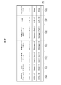
- the port management table 73 is a table used for managing each port (front-end port 24A or back-end port 24B) of each physical storage device 3 constituting the virtual storage device VST, as shown in FIG. , A physical storage device ID column 73A, a physical storage device port ID column 73B, a port name column 73C, a remaining bandwidth column 73D, and a backend port information column 73E.
- the physical storage device ID column 73A stores the physical storage device ID of each physical storage device 3 constituting the virtual storage device VST, and the physical storage device port ID column 73B stores each physical storage device 3 in the corresponding physical storage device 3. Stores the port ID of the port.
- the port name column 73C stores the port name of the port displayed on the access path diagnosis result screen 90 (FIG. 17), which will be described later, and the remaining bandwidth column 73D displays the usable bandwidth of the corresponding port. Stores the current remaining bandwidth minus the bandwidth in use.
- backend port information information indicating whether or not the corresponding port is the backend port 24B (hereinafter referred to as backend port information) is stored in the backend port information column 73E.
- the back-end port information column 73E stores “true” when the corresponding port is the back-end port 24B, and stores “false” when the port is not the back-end port 24B.
- the port pair management table 74 includes a set of a port of one physical storage device 3 and a port of the other physical storage device 3 to which paths connecting the physical storage devices 3 are connected, and a path in the physical storage device 3.
- 11 is a table used for managing a back-end port pair composed of a set of ports connected via the physical storage device ID-A column 74A, physical storage device port ID- A column 74B, physical storage device ID-B column 74C, physical storage device port ID-B column 74D, inter-physical storage device port pair information column 74E, access path information column 74F, virtual logical volume ID column 74G, and host computer ID column 74H Consists of
- the physical storage device ID-A column 74A and the physical storage device port ID-A column 74B the physical storage device ID of one physical storage device 3 to which the path corresponding to the entry (row) is connected, and The port ID of the port to which the path in the physical storage device 3 is connected is stored, and the physical storage device ID-B column 74C and the physical storage device port ID-B column 74D each have the other connected to the path.
- the physical storage device ID of the physical storage device 3 and the port ID of the port connected to the path in the physical storage device 3 are stored.
- inter-physical storage device port pair information column 74E information indicating whether or not the corresponding path is a path connecting the physical storage devices 3 is stored. Specifically, in the inter-physical storage device port pair information column 74E, “true” is stored when the path is a path connecting the physical storage devices 3, and the path connects the physical storage devices 3. When it is not a path (that is, when the path is a path connecting one port and another port in the same physical storage device 3), “false” is stored.
- the virtual logical volume ID column 74G stores the volume ID of the virtual logical volume VVOL to which the corresponding path is connected
- the host computer ID column 74H stores the host of the host computer 2 that can access the virtual logical volume VVOL.
- a computer ID is stored.
- the access path information column 74F stores information indicating whether or not the corresponding path is an access path. Specifically, the access path information column 74F stores “true” when the corresponding path is an access path, and stores “false” when the path is not an access path.
- the access path refers to a path used when the host computer 2 accesses data stored in the corresponding virtual logical volume VVOL.
- the data bias threshold management table 75 is a table used for managing the above-mentioned data bias threshold and the port free bandwidth threshold set by the system administrator, and includes a data bias threshold column and a port free bandwidth threshold column.
- the data bias threshold column stores the data bias threshold
- the port free bandwidth threshold column stores the port free bandwidth threshold.
- the exclusion target volume management table 76 is a table used by the system administrator to manage the virtual logical volume VVOL that should be excluded from the access path diagnosis process (FIG. 20) and the access path automatic change process (FIG. 27).
- the virtual logical volume ID of the virtual logical volume VVOL to be excluded from the access path diagnosis process and the access path automatic change process set in advance by the system administrator is stored.
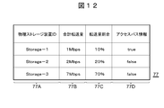
- the data bias information 77 is information used for managing the biased state of data distribution to each physical storage device 3 constituting the virtual logical volume VVOL, and will be described later with access path diagnosis processing (FIGS. 20A and 20B). ) Or access path search processing (FIG. 22), the virtual logical volume VVOL that is the target at that time is created.
- the data bias information 77 includes a physical storage device ID column 77A, a total transfer amount column 77B, a transfer amount ratio column 77C, and an access path information column 77D.
- the physical storage device ID column 77A stores the physical storage device IDs of all physical storage devices 3 constituting the target virtual logical volume VVOL, and the total transfer amount column 77B stores the virtual logical volume VVOL.
- the total amount of data transferred to the corresponding physical storage device 3 among all the data transferred to (1) is stored (hereinafter referred to as the total transfer amount).
- the corresponding physical storage device 3 for all the data transferred to the target virtual logical volume VVOL (corresponding to the total transfer amount of each entry of the data bias information 77). Stores the ratio of the amount of data transferred to the other physical storage device 3 via the inter-device communication network 7.
- access path information indicating whether or not the path from the host computer 2 to the corresponding physical storage device 3 is an access path.
- the access path information column 77D “true” is stored when the path from the host computer 2 to the corresponding physical storage device 3 is an access path, and when the path is not an access path, “true” is stored. “false” is stored.
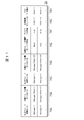
- the remaining bandwidth corrected port information 78 is information used for managing the remaining bandwidth of each port in each physical storage device 3 when there is no data transfer with the corresponding virtual logical volume VVOL. Yes, it is created in an access path search process (FIG. 22) described later. As shown in FIG. 13, the remaining bandwidth corrected port information 78 includes a physical storage device ID column 78A, a physical storage device port ID column 78B, a port name column 78C, a remaining bandwidth column 78D, and a backend port information column 78E. Composed.
- the physical storage device ID column 78A the physical storage device ID of each physical storage device 3 constituting the corresponding virtual logical volume VVOL is stored.
- the physical storage device port ID column 78B stores the port ID of the port (front-end port 24A or back-end port 24B) in the physical storage device 3 connected to the virtual logical volume VVOL, and the port name column 78C.
- the port name of the port displayed on the access path diagnosis result screen 90 (FIG. 17) and the like described later is stored.
- the remaining bandwidth column 78D stores the remaining bandwidth of the corresponding port when it is assumed that there is no data transfer to the corresponding virtual logical volume VVOL
- the back-end port information column 78E stores the port's remaining bandwidth.
- Information indicating whether the port is an end port is stored. Specifically, “true” is stored in the back-end port information column 78E when the corresponding port is a back-end port, and “false” is stored when the port is not a back-end port.
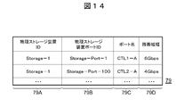
- the changeable front-end port information 79 is a list of front-end ports 24A (FIG. 3) having a remaining bandwidth that can be a new access path to the host computer 2, and a front-end port search process described later with reference to FIG. Created in. As shown in FIG. 14, the changeable front-end port information 79 includes a physical storage ID column 79A, a physical storage device port ID column 79B, a port name column 79C, and a remaining bandwidth column 79D.
- the access path change destination with the host computer 2 among the front end ports 24A (FIG. 3) in the physical storage device 3 constituting the corresponding virtual logical volume VVOL is displayed.
- the port ID of the front end port 24A having the remaining bandwidth to be obtained is stored, and the physical storage device ID of the physical storage device 3 including the front end port 24A is stored in the physical storage device ID column 79A.
- the port name column 79C stores the port name of the front end port 24A displayed on the access path diagnosis result screen 90 and the like described later with reference to FIG. 17, and the remaining bandwidth column 79D stores the corresponding virtual logical volume VVOL. The remaining bandwidth of the corresponding front-end port 24A when it is assumed that there is no data input / output to is stored.
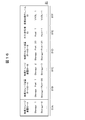
- the change-target front-end port information 80 is the same between the host computer 2 and the virtual storage system VST even when considering the remaining bandwidth of the back-end port 24B among the front-end ports 24A registered in the changeable front-end port information 79. Is a list of front-end ports 24A to which paths that can be changed destinations of access paths for connecting are connected. In the change target front-end port information 80, one front-end port 24A is registered for one virtual logical volume VVOL. The change target front-end port information 80 is created in an access path search process described later with reference to FIG.
- the change target front-end port information 80 includes a physical storage device ID column 80A, a physical storage device port ID column 80B, a port name column 80C, a remaining bandwidth column 80D, a host computer ID column 80E, and a virtual logical It consists of a volume ID column 80F.
- the physical storage device port ID column 80B stores the port ID of the front-end port 24A to which the path that can be changed is connected, and the physical storage device ID column 80A contains the physical with the corresponding front-end port 24A.
- the physical storage device ID of the storage device 3 is stored.
- the port name column 80C stores the port name of the front end port 24A displayed on the access path diagnosis result screen 90 and the like described later with reference to FIG. 17, and the remaining bandwidth column 80D stores the corresponding front end port 24A. Is stored.
- the host computer ID column 80E stores the host computer ID of the host computer 2 connected to the corresponding front-end port 24A, and the virtual logical volume ID column 80F can be accessed via the front-end port 24A. Stores the volume ID of the virtual logical volume VVOL.
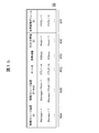
- the back-end port pair information 81 to be changed includes one physical to which a back-end path that can be an access path change destination is connected among paths connecting the physical storage devices 3 (hereinafter referred to as a back-end path). It is a list of groups of back end ports 24B of the storage apparatus 3 and back end ports 3 of the other physical storage apparatus 3 (hereinafter referred to as back end port pairs). In the back-end port pair information 81 to be changed, one back-end port pair is registered for each physical storage device 3. The change-target back-end port pair information 81 is created in the back-end port pair search process described later with reference to FIG.
- the change-target back-end port pair information 81 includes a physical storage device ID-A column 81A, a physical storage device port ID-A column 81B, a physical storage device ID-B column 81C, and a physical storage device port ID. -B column 81D, host computer ID column 81E, and virtual logical volume ID column 81F.
- the physical storage device ID-A column 81A and the physical storage device port ID-A column 81B the physical storage device ID of one physical storage device 3 to which the back-end path corresponding to the entry (row) is connected, respectively. And the port ID of the port to which the back-end path in the physical storage device 3 is connected, respectively, and the physical storage device ID-B column 81C and the physical storage device port ID-B column 81D respectively.
- the physical storage device ID of the other physical storage device 3 to which the end path is connected and the port ID of the port to which the back end path of the physical storage device 3 is connected are stored.
- the host computer ID column 81E stores the host computer ID of the host computer 2 that uses the corresponding back-end path as an access path.
- the virtual logical volume ID column 81F stores the host computer ID via the back-end path. 2 stores the volume ID of the virtual logical volume VVOL accessible by 2.
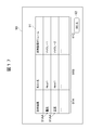
- FIG. 17 shows a configuration example of an access path diagnosis result screen 90 that can be displayed on the management client 5 by a predetermined operation.
- This access path diagnosis result screen 90 displays the operating status of the access path used when the host computer 2 accesses the virtual logical volume VVOL, detected by the access path diagnosis process described later with reference to FIGS. 20A and 20B. This is a GUI screen.
- the access path diagnosis result screen 90 includes an access path operating status list 91 and a close button 92.
- the access path operation status list 91 is a list of diagnosis results for the operation status of each access path from the host computer 2 to each virtual logical volume VVOL, and is composed of a diagnosis result column 91A, a host name column 91B, and a virtual logical volume column 91C. Is done.
- the host name column 91B displays the name (host name) of the host computer 2 to which the corresponding access path is connected, and the virtual logical volume column 91C can be accessed by the host computer 2 via the access path.
- the virtual logical volume ID of the virtual logical volume VVOL is displayed.
- diagnosis result column 91A the diagnosis result for the corresponding access path is displayed.
- the diagnostic results include “warning” and “normal”.
- Warning indicates that it is determined that there is a problem with the access path as a result of diagnosing the corresponding access path.
- “there is a problem in the access path” means that the front end port 24A (see FIG. 4) to which the access path in the physical storage device 3 directly connected to the host computer 2 via the access path is connected.
- “Normal” indicates that it is determined that there is no problem in the access path as a result of diagnosing the corresponding access path.
- “no problem in access path” means that the remaining bandwidth of the front-end port 24A (FIG. 3) of the physical storage device 3 to which the access path is connected is equal to or greater than the port free bandwidth threshold.
- the remaining bandwidth of all the back-end ports 24B in these physical storage devices 3 to which the back-end path used as an access path from the physical storage device 3 to another physical storage device 3 is connected is the port.
- the amount of data larger than the data bias threshold The state where the data of is stored.
- the system administrator clicks the character string 91AA representing the diagnosis result ("warning" or "normal") displayed in the desired diagnosis result column 91A of the access path operating state list 91, thereby accessing the access path diagnosis result screen.
- an access path diagnosis result detail screen 100 as shown in FIG. 18 can be displayed.
- clicking a close button 92 the access path diagnosis result screen 90 can be closed.
- the access path diagnosis result detail screen 100 is a GUI screen for displaying details of an access path diagnosis result designated on the access path diagnosis result screen 90 (clicking on the character string 91AA representing the diagnosis result). As shown in FIG. 18, the access path diagnosis result detail screen 100 includes a diagnosis result detail display field 101, a search button 102, and a close button 103.
- the host computer 2 and a pictorial symbol 101A schematically representing each physical storage device 3 constituting the corresponding virtual logical volume VVOL in the virtual storage device VST, and a virtual symbol from the host computer 2 are displayed.
- a representing line 101C and the like are displayed.
- Information indicating the I / O ratio (“direct I / O ratio”) 101D and information indicating the remaining bandwidth of the front-end port 24A (FIG. 3) or back-end port 24B to which the corresponding access path is connected ( “Remaining bandwidth”) 101E and the like are displayed.
- a warning mark 101F indicating this is displayed at a problem location.
- the data corresponding to the data amount less than the data bias threshold is stored among the data stored in the corresponding virtual logical volume VVOL. If not, a warning mark 101F is displayed in the host computer 2.
- the remaining bandwidth of the front end port 24A (FIG. 3) to which the access path is connected in the physical storage device 3 directly connected to the host computer 2 via the access path is less than the port free bandwidth threshold described above.
- a warning mark 101F is displayed in the vicinity of the line 101B representing the access path connecting the host computer 2 and the physical storage device 3.
- the remaining bandwidth of one of the back-end ports 24B in the physical storage device 3 to which the back-end path used as an access path from the physical storage device 3 to another physical storage device 3 is connected is described above. If it is less than the port available bandwidth threshold, a warning mark 101F is displayed near the line 101C representing the access path connecting these physical storage apparatuses 3.
- the system administrator can close the access path diagnosis result detail screen 100 by clicking the close button 103, and can search for the optimum access path as the access path switching destination by clicking the search button 102. It is possible to cause the management computer 4 to execute the access path search process (FIG. 22).
- FIG. 19 shows the access path displayed on the management client 5 as the processing result of the access path search process instead of the access path diagnosis result detail screen 100 after the above access path search process is executed in the management computer 4.
- the structural example of the change screen 110 is shown.
- the access path change screen 110 includes a pre-update state display field 111, a post-update state display field 112, a change button 113, and a close button 114.
- the contents displayed in the diagnosis result detail display field 101 of the immediately preceding access path diagnosis result detail screen 100 are displayed as they are.
- the post-update state display field 112 the optimum access path between the host computer 2 and the physical storage device 3, the inside of the physical storage device 3, and between the physical storage devices 3 detected by the access path search process is displayed before the update. It is displayed in the same display form as the status display field 111.
- the pre-update status display field 111 and post-update status display field 112 are directly connected to the access path from the host computer 2 among the I / Os issued from the host computer 2 to the corresponding virtual logical volume VVOL.
- Information (“direct I / O ratio”) 111D, 112D, the front end port 24A (FIG. 3) or the back end port to which the corresponding access path is connected Information indicating the remaining bandwidth of 24B (“remaining bandwidth”) 111E, 112E, etc. is displayed. Further, the above-mentioned warning mark 111F is also displayed in the diagnosis result detail display field at a problem location.
- the system administrator desires to change the access path from the host computer 2 to the virtual logical volume VVOL to the state displayed in the post-update state display field 112, the system administrator clicks the change button 113.
- the access path from the host computer 2 to the virtual logical volume VVOL is changed to the access path displayed in the post-update status display field 112.
- the system administrator can close this access path change screen 110 by clicking the close button 114 without changing the access path from the host computer 2 to the virtual logical volume VVOL.
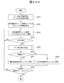
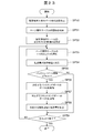
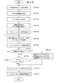
- the access path diagnosis unit 60 When the access path diagnosis unit 60 receives the access path diagnosis request from the management client 5, the access path diagnosis unit 60 starts the access path diagnosis process shown in FIGS. 20A and 20B.
- the access path diagnosis unit 60 first acquires a data bias threshold and a port free bandwidth threshold from the data bias threshold management table 75 (SP1), and thereafter, all entries of the virtual logical volume management table 71 (FIG. 8). Information is acquired (SP2).
- the access path diagnosis unit 60 selects one entry that has not been processed in steps SP3 to SP9 from the entries whose information has been acquired in step SP2 (SP3), and the virtual logical volume corresponding to the entry. It is determined whether or not the VVOL is a virtual logical volume VVOL to be excluded from access path diagnosis processing (SP4). Specifically, the access path diagnosis unit 60 registers the virtual logical volume ID stored in the virtual logical volume ID column 71A (FIG. 8) of the entry selected in step SP3 in the exclusion target volume management table 76 in step SP4. It is judged whether it is done.
- step SP4 When the access path diagnosis unit 60 obtains a positive result in step SP4, it returns to step SP3, and thereafter repeats the loop of step SP3-step SP4-step SP3 until a positive result is obtained in step SP4.
- the access path diagnosis unit 60 obtains a negative result in step SP4, it calls the data deviation calculation unit 54 (FIG. 6), and the virtual logical volume of the entry of the virtual logical volume management table 71 selected in step SP3.
- the virtual logical volume ID stored in the ID column 71A and the host computer ID stored in the host computer ID column 71B are given as arguments to the data bias calculation unit 54 (SP5).
- a data bias calculation process (FIG. 21), which will be described later, is executed by the data bias calculator 54, and data bias information 77 (FIG. 12) for the virtual logical volume VVOL corresponding to the entry selected in step SP3 is created.
- the access path diagnosis unit 60 based on the data bias information 77 created by the data bias calculation unit 54 in step SP5, and the data bias threshold and the port free bandwidth threshold acquired in step SP1, from the host computer 2 It is then determined whether there is a problem in the access path to the target virtual logical volume VVOL (SP6). This determination is used for data transfer between the physical storage devices 3 among the paths connecting the physical storage device 3 directly connected to the host computer 2 via the access path and the other physical storage devices 3. The ratio of the current used bandwidth (access amount) to the maximum bandwidth of the path is
- the access path diagnosis unit 60 determines whether or not the target virtual logical volume VVOL satisfies at least one of the following conditions (A) to (C).
- the physical storage device corresponding to the entry in which “true” is stored in the access path information column 77D that is, the physical storage directly connected to the host computer 2 via the access path
- the maximum usable bandwidth of the front end port 24A to which the access path to the host computer 2 is connected (hereinafter referred to as the maximum bandwidth).
- the ratio of the remaining bandwidth of the front end port 24A with respect to the call) is smaller than the port free bandwidth threshold acquired in step SP1.
- condition (A) described above is a condition for detecting a bias in data input / output to / from physical storage devices 3 other than the physical storage device 3 directly connected to the host computer 2 via an access path.
- the access path diagnosis unit 60 obtains a positive result in the determination at step SP6 (when at least one of the above three conditions is satisfied), there is a problem with the target virtual logical volume VVOL in the access path.
- a warning virtual logical volume representing a certain virtual logical volume VVOL is classified (SP7).
- the access path diagnosis unit 60 accesses the target virtual logical volume VVOL.
- the virtual logical volume VVOL having no path problem is classified as a normal virtual logical volume (SP8).
- the access path diagnosis unit 60 determines whether or not the processing of step SP4 to step SP8 has been executed for all entries of the virtual logical volume management table 71 (SP9). If the access path diagnosis unit 60 obtains a negative result in this determination, it returns to step SP3, and thereafter repeats the processing of step SP3 to step SP9 until an affirmative result is obtained in step SP9.
- the access path diagnosis unit 60 When the access path diagnosis unit 60 eventually classifies all the virtual logical volumes VVOL registered in the virtual logical volume management table 71 into warning virtual logical volumes or normal virtual logical volumes, it obtains a positive result in step SP9. , The access path of the virtual logical volume ID, host name, and attribute information indicating whether it is a warning virtual logical volume or a normal virtual logical volume of all virtual logical volumes VVOL registered in the virtual logical volume management table 71 As diagnosis result information, it is transmitted to the management client 5 together with a display command of the access path diagnosis result screen 90 (FIG. 17) (SP10).
- SP10 display command of the access path diagnosis result screen 90
- the management client 5 that has received the display command and the access path diagnosis result information displays the access path diagnosis result screen 90 described above with reference to FIG. 17 based on the access path diagnosis result information.
- the management client 5 sets the warning virtual logical volume in the access path in the diagnosis result column 91A (FIG. 17) of the corresponding entry in the diagnosis result list 91 (FIG. 17) in the access path diagnosis result screen 90.
- a character string 91AA (FIG. 17), which is information indicating that there is a problem, is displayed.
- the “normal” character string 91AA which is information to be displayed, is displayed.
- the access path diagnosis unit 60 stores the “warning” or “normal” character string 91AA stored in the close button 92 of the access path diagnosis result screen 90 or the diagnosis result column 91A of the diagnosis result list 91. Waiting for a click (SP11, SP12).
- the access path diagnosis unit 60 instructs the management client 5 to close the access path diagnosis result screen 90 (SP17), and thereafter ends this access path diagnosis process.
- the access path diagnosis unit 60 described above with reference to FIG.
- the display instruction of the access path diagnosis result detail screen 100 and various information necessary for display of the access path diagnosis result detail screen 100 are transmitted to the management client 5 (SP13).
- the access path diagnosis result detail screen 100 is displayed by the management client 5.
- the access path diagnosis unit 60 waits for the close button 103 or the search button 102 on the access path diagnosis result detail screen 100 to be clicked (SP14, SP15). Then, when the close button 103 is clicked, the access path diagnosis unit 60 instructs the management client 5 to close the access path diagnosis result detail screen 100 (SP17), and thereafter ends this access path diagnosis process. .
- the access path diagnosis unit 60 calls the access path search unit 61 (FIG. 6) and makes the access path search unit 61 the target virtual logical volume at that time. After giving the virtual logical volume ID of the VVOL, the host computer ID of the host computer 2, and the access path search processing execution command (SP16), the access path diagnosis processing is terminated.
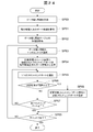
- FIG. 21 is executed by the data bias calculation unit 54 (FIG. 6) called by the access path diagnosis unit 60 in step SP5 of the access path diagnosis processing (FIGS. 20A and 20B) described above.
- the processing procedure of the data bias calculation process to be performed is shown.
- the data bias calculation unit 54 When the data bias calculation unit 54 receives an access path search process execution command from the access path diagnosis unit 60, the data bias calculation unit 54 starts the data bias calculation process shown in FIG. ), The virtual logical volume ID of the target virtual logical volume VVOL and the host computer ID of the host computer 2 are sequentially received (SP20, SP21).
- the data bias calculation unit 54 has the same virtual logical volume ID as the virtual logical volume ID of the target virtual logical volume VVOL received in step SP20 among the entries of the page management table 72 (FIG. 9). Information of all entries (rows) stored in 72B (FIG. 9) is acquired (SP22).
- the data bias calculation unit 54 temporarily creates data bias information 77 (FIG. 6) by executing the following (A) to (C) based on the information acquired in step SP22 (SP23).
- the data bias calculation unit 54 among the entries of the path management table 70 (FIG. 7), the virtual logical volume ID stored in the virtual logical volume ID column 70A (FIG. 7) and the host computer ID column 70B (FIG. 7). 7)
- the host computer ID stored in 7) is searched for the same entry as the virtual logical volume ID and host computer ID received in step SP20 and step SP21, respectively.
- the entry information is acquired from the path management table 70 (SP24).
- the data bias calculation unit 54 is directly connected to the host computer 2 among the plurality of physical storage devices 3 constituting the target virtual logical volume VVOL based on the information acquired in step SP24.
- the physical storage device 3 is identified, “true” is stored in the access path information column 77D (FIG. 12) of the entry corresponding to the physical storage device 3 among the entries of the data bias information 77, and other entries “False” is stored in the access path information column 77D (SP25).
- Data bias information 77 is completed by the above processing. Then, the data bias calculation unit 54 thereafter ends this data bias calculation process.
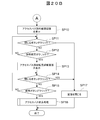
- the access path search unit 61 that has received the access path search instruction searches for a path that can be an access path change destination when the target host computer 2 accesses the target virtual logical volume VVOL according to the processing procedure shown in FIG. .
- the access path search unit 61 starts the access path search process shown in FIG. 22 when called by the access path diagnosis unit 60.
- the virtual path of the target virtual logical volume VVOL given from the access path diagnosis unit 60 is started.
- the logical volume ID and the host computer ID of the target host computer 2 are received (SP30, SP31).
- the access path search unit 61 calls the data bias calculation unit 54 (FIG. 6) using the virtual logical volume ID and host computer ID received in step SP30 and step SP31 as arguments (SP32).
- the data bias calculation unit 54 called by the access path search unit 61 executes the data bias calculation process described above with reference to FIG. 21, thereby obtaining the data bias information 77 (FIG. 12) corresponding to the target virtual logical volume VVOL. create.
- the access path search unit 61 calls the remaining bandwidth corrected port information creation unit 55 using the virtual logical volume ID and host computer ID received in step SP30 and step SP31 as arguments (SP33).
- the remaining bandwidth corrected port information creation unit 55 called by the access path search unit 61 executes the remaining bandwidth corrected port information creation process described later with reference to FIG. 23, thereby transferring data to the target virtual logical volume VVOL.
- the remaining bandwidth of each port of each physical storage device 3 constituting the target virtual logical volume VVOL is calculated, and the remaining bandwidth corrected port information 78 (corresponding to the target virtual logical volume VVOL based on the calculation result) FIG. 13) is created.
- the access path search unit 61 calls the front end port search unit 56 (FIG. 6) (SP34).
- the front-end port search unit 56 called by the access path search unit 61 executes the front-end port search process described later with reference to FIG. 24, whereby each of the physical storage devices 3 constituting the target virtual logical volume VVOL.
- the front end port 24A From the front end port 24A, the front end port 24A to which the front end path that can change the access path with the host computer 2 is searched, and the target virtual logical volume VVOL is supported based on the search result.
- the changeable front end port information 79 (FIG. 14) is created.
- the access path search unit 61 performs the processing of steps SP36 to SP39 from the front end port 24A registered in the changeable front end port information 79 created by the front end port search unit 56 in step SP34.
- One front-end port 24A of the physical storage device 3 that has not been executed yet and has the largest total transfer amount is selected (SP35).
- the access path search unit 61 calls the back end port pair search unit 57 using the physical storage device ID of the physical storage device 3 including the front end port 24A selected in step SP35 as an argument (SP36).
- SP36 the back-end port pair search unit 57 called by the access path search unit 61 executes a back-end port pair search process described later with reference to FIG.
- the access path search unit 61 determines whether or not the return value from the backend port pair search unit 57 is “false” (SP37). If the access path search unit 61 obtains an affirmative result in this determination, it returns to step SP35. Thereafter, the access path search unit 61 sequentially switches the entry selected in step SP35 to one having a small total transfer amount, while step SP35 to step SP38. Repeat the process.
- the access path search unit 61 When the access path search unit 61 obtains a negative result in the determination at step SP37, it receives the front end port 24A corresponding to the entry of the changeable front end port information 79 selected at step SP35 at step SP30. Front-end port information 80 to be changed as a front-end port that can be used to change the access path between the host computer 2 and the physical storage device 3 used when accessing the virtual logical volume VVOL to which the virtual logical volume ID is assigned (see FIG. 15).
- the physical storage device 3 (that is, the target virtual logical volume) having a larger total transfer amount of data input to and output from the target virtual logical volume VVOL. Even when considering the remaining bandwidth of the back end port 24B from the front end port 24A of the physical storage device 3) allocating the most storage area to the VVOL, the host computer 2 and the virtual storage device VST are connected. The front end port 24A to which the path that can be the access path change destination is connected is selected, and this is registered in the change target front end port information 80.
- the access path search unit 61 calls the access path display unit 62 with information necessary for displaying the access path change screen 110 described above with reference to FIG. 19 as an argument (SP40).
- the access path display unit 62 displays the access path change screen 110 in which the change content recommended as the access path change content is described in the post-update status display field 112 based on the information given as an argument.
- the access path search unit 61 thereafter ends this access path search process.
- the access path search unit 61 executes the processing of step SP35 to step SP38 for all the front end ports 24A registered in the changeable front end port information 79, but does not obtain an affirmative result in step SP37.
- the management client 5 displays information indicating that there is no option that can improve the performance by changing the access path. Incidentally, information indicating how much data stored in the corresponding virtual logical volume VVOL is distributed to the physical storage devices 3 other than the physical storage device 3 directly connected to the host computer 2 via the access path is managed. In addition to displaying on the client 5, the user is asked how much data should be concentrated on the physical storage device 3 directly connected to the host computer 2 via the access path, and the data is moved based on the user's response. Also good.
- data movement may be automatically executed based on a predetermined condition.
- the access path option cannot be selected due to a lack of remaining bandwidth of the front-end port or the back-end port
- information recommending that the port of the physical storage device 3 be added is sent to the management client 5. You may make it display.
- the access path search unit 61 thereafter ends this access path search process.
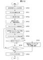
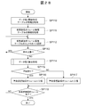
- FIG. 23 shows the remaining bandwidth corrected port information creation unit 55 called by the access path search unit 61 in step SP33 of the access path retrieval processing (FIG. 22). The specific processing procedure of the remaining bandwidth corrected port information creation processing to be executed is shown.
- the remaining band corrected port information creating unit 55 When called by the access path search unit 61, the remaining band corrected port information creating unit 55 starts this remaining band corrected port information creating process, and first duplicates the port management table 73 (FIG. 10) to copy the remaining band.
- the corrected port information 78 (FIG. 13) is temporarily created (SP50). Further, the remaining bandwidth corrected port information creation unit 55 acquires information of all entries from the page management table 72 (FIG. 9) (SP51).
- the remaining bandwidth corrected port information creation unit 55 sends the virtual logical volume ID of the target virtual logical volume VVOL given as an argument from the call source (here, the access path search unit 61), and the host computer of the target host computer 2 ID is received (SP52), and thereafter, one entry (logical page LP) is selected from each entry of the page management table 72 for which information has been acquired in step SP52 (SP53).
- the remaining bandwidth corrected port information creating unit 55 fills the physical storage device port ID column 72G (FIG. 9) of the entry selected in step SP53 among the entries of the remaining bandwidth corrected port information 78 provisionally created in step SP50.
- An entry in which the same port ID as the stored port ID is stored in the physical storage device port ID column 78B (FIG. 13) is searched and stored in the remaining bandwidth column 78D (FIG. 13) of the entry detected by the search.
- the transfer amount stored in the transfer amount column 72E (FIG. 9) of the entry selected in step SP53 is added to the remaining bandwidth that has been set (SP54).
- the corresponding physical storage apparatus 3 when there is no data input / output to / from the target logical page (referred to as the logical page corresponding to the entry selected in step SP53) LP of the target virtual logical volume VVOL at that time.
- the remaining bandwidth of the corresponding port is calculated.
- the remaining bandwidth corrected port information creation unit 55 among the entries of the remaining bandwidth corrected port information 78 temporarily created in step SP50, the physical storage device port ID column 72G of the entry selected in step SP53 (FIG. 9). Whether or not “true” is stored in the back-end information column 78E (FIG. 13) of the entry in which the same port ID as the port ID stored in is stored in the physical storage device port ID column 78B (FIG. 13) Is determined (SP55).
- step SP53 to obtain a negative result in this determination means that the data stored in the logical page corresponding to the entry selected in step SP53 is held in the physical storage device 3 in which the host computer 2 and the access path are directly connected. Means that Thus, at this time, the remaining band corrected port information creation unit 55 proceeds to step SP58.
- obtaining a positive result in the determination in step SP55 means that the data stored in the logical page corresponding to the entry selected in step SP53 is the physical storage device in which the host computer 2 and the access path are directly connected. It means that it is held in a physical storage device 3 other than 3.
- the remaining bandwidth corrected port information creation unit 55 refers to the port pair management table 74 (FIG. 11) and is stored in the physical storage device port ID column 72G (FIG. 9) of the entry selected in step SP53.
- a port ID of a port constituting a back-end port pair with a port to which a given port ID is assigned (hereinafter referred to as a target port) is acquired (SP56).
- the port ID acquired at this time is the back end port 24B connected to the target port via the access path among the ports of the physical storage device 3 directly connected to the host computer 2 via the access path. Port ID.
- the remaining bandwidth corrected port information creation unit 55 searches the port pair management table 74 for an entry satisfying all the following conditions (A) to (E), and the physical storage of the entry detected by the search: Of the port IDs stored in the device port ID-A column 74B (FIG. 11) and the physical storage device port ID-B column 74D (FIG. 11), the physical storage device port ID column 72G ( A port ID different from the port ID stored in FIG. 9) is acquired.
- the remaining bandwidth corrected port information creation unit 55 is connected to the host computer 2 via the access path among the ports of the physical storage device 3 including the back-end port 24B to which the port ID obtained in step SP56 is assigned.
- the port ID of the designated port is acquired (SP57).
- the port ID acquired at this time is the front-end port 24A to which the access path is connected among the ports of the physical storage device 3 directly connected to the host computer 2 via the access path.
- the remaining bandwidth corrected port information creation unit 55 searches the port pair management table 74 (FIG. 11) for an entry that satisfies all the following conditions (A) to (D), and detects the entry by the search.
- the physical storage device port of the entry selected in step SP53 A port ID different from the port ID stored in the ID column 72G (FIG. 9) is acquired.
- the same port ID as the port ID acquired in step SP56 is stored in either the physical storage device port ID-A column 74B or the physical storage device port ID-B column 74D.
- “true” is stored in the access path information column 74F (FIG. 11).
- C) The same virtual logical volume ID as the virtual logical volume ID received in step SP52 is stored in the virtual logical volume ID column 74G (FIG. 11).
- D) The same host computer ID as the host computer ID received in step SP52 is stored in the host computer ID column 74H (FIG. 11).
- the remaining bandwidth corrected port information creation unit 55 has the same port ID as the port ID acquired in step SP56 among the entries of the remaining bandwidth corrected port information 78 (FIG. 13).
- the entry stored in FIG. 13) is searched, and the transfer amount column 72E of the entry selected in step SP53 is added to the remaining bandwidth stored in the remaining bandwidth column 78D of the entry detected by the search (FIG. 9). Is added to the transfer amount (SP58).
- the remaining bandwidth corrected port information creation unit 55 has the same port ID as the port ID acquired in step SP57 among the entries of the remaining bandwidth corrected port information 78 (FIG. 13).
- the entry stored in (FIG. 13) is searched, and the transfer amount column 72E of the entry selected in step SP53 (FIG. 9) is added to the remaining bandwidth stored in the remaining bandwidth column 78D of the entry detected by the search.
- the transfer amount stored in () is added (SP58).
- the remaining bandwidth corrected port information creation unit 55 determines whether or not the processing of step SP53 to step SP58 has been executed for all entries of the page management table 72 (FIG. 9) (SP59). When the remaining band corrected port information creation unit 55 obtains a negative result in this determination, it returns to step SP53, and then sequentially switches the entry of the page management table 72 selected in step SP53 to another unprocessed entry. The processing from step SP53 to step SP59 is repeated until a positive result is obtained in step SP59.
- the remaining bandwidth corrected port information 78 in which the remaining bandwidth of each port of each physical storage device 3 when there is no data input / output with respect to the target virtual logical volume VVOL can be completed.
- step SP59 When the remaining band corrected port information creation unit 55 eventually obtains a positive result in step SP59 by completing the processing of step SP53 to step SP58 for all entries in the page management table 72, this remaining band corrected port is obtained.
- FIG. 24 shows a front end port search process executed by the front end port search unit 56 called by the access path search unit 61 in step SP34 of the access path search process (FIG. 22). The specific processing procedure of is shown.
- the front end port search unit 56 When called by the access path search unit 61, the front end port search unit 56 starts this front end port search process. First, the data bias information 77 (FIG. 12), the remaining band corrected port information 78 (FIG. 13) and The data bias threshold and the port free bandwidth threshold stored in the data bias threshold management table 75 are sequentially acquired (SP60 to SP62).
- the front-end port search unit 56 selects one entry from the entries of the data bias information 77 acquired in step SP60 (SP63), and among the entries of the remaining bandwidth corrected port information 78, in step SP63.
- the entry corresponding to each front end port 24A of the physical storage device 3 corresponding to the selected entry is searched, and the information of all corresponding entries is acquired from the remaining bandwidth corrected port information 78 (SP64).
- the front end port search unit 56 searches the entries of the remaining bandwidth corrected port information 78 for entries that satisfy both of the following conditions (A) and (B), and information on all corresponding entries: Is acquired from the remaining band corrected port information 78.
- A The same physical storage device ID as the physical storage device ID stored in the physical storage device ID column 77A (FIG. 12) of the entry of the data bias information 77 selected in step SP63 is the physical storage device ID column 78A (FIG. 13).
- “false” is stored in the back-end port information column 78E (FIG. 13).
- the front-end port search unit 56 selects one entry from the entries of the remaining bandwidth corrected port information 78 detected by the search in step SP64 (SP65).
- the front-end port search unit 56 sets the total transfer amount of the physical storage device 3 corresponding to the entry of the data bias information 77 selected in step SP63 as the entry of the remaining bandwidth corrected port information 78 selected in step SP65. It is determined whether or not the value subtracted from the remaining bandwidth of the corresponding front end port 24A is equal to or greater than the port free bandwidth threshold (SP66). This determination is made by acquiring the total transfer amount stored in the total transfer amount column 77B (FIG. 12) of the entry of the data bias information 77 selected in step SP63, and using the acquired total transfer amount in the entry selected in step SP65. This is performed by subtracting from the remaining bandwidth stored in the remaining bandwidth column 78D (FIG. 13) and determining whether the subtraction result is equal to or greater than the port free bandwidth threshold.
- SP66 port free bandwidth threshold
- the front-end port search unit 56 determines whether or not the processing of step SP66 has been executed for all the entries detected in the search of step SP64 (SP67). Further, when the front end port search unit 56 obtains a negative result in this determination, it returns to step SP65, and thereafter repeats the processing of step SP65 to step SP67 until a positive result is obtained in step SP66 or step SP67.
- step SP66 If the front end port search unit 56 does not obtain a positive result in step SP66 for the front end port 24A corresponding to each entry detected by the search in step SP64 but obtains a positive result in step SP67, the process proceeds to step SP69. .
- the front end port search unit 56 obtains a positive result in the determination at step SP66 for any one of the front end ports 24A corresponding to each entry detected by the search at step SP64. Then, the front end port 24A is registered in the changeable front end port information 79 (FIG. 14) (SP68), and then the process proceeds to step SP69.
- the front-end port search unit 56 determines whether or not the processing of steps SP63 to SP68 has been executed for all entries of the data bias information 77 (SP69). If the front end port search unit 56 obtains a negative result in this determination, it returns to step SP63, and thereafter, the entry selected in step SP63 is sequentially switched to another unprocessed entry, and the processing of step SP63 to step SP69 is performed. repeat.
- Front end port information 79 will be sequentially registered.
- step SP63 finishes executing the processing of step SP63 to step SP68 for all entries of the data bias information 77, and obtains a positive result in step SP69, the front end port search processing ends. .
- FIG. 25 shows the backend port executed by the backend port pair search unit 57 called by the access path search unit 61 in step SP36 of the access path search process (FIG. 22). A specific processing procedure of the pair search processing is shown.
- the back-end port pair search unit 57 creates a copy of the data bias information 77 (FIG. 12) (SP71), and among the entries in the created copy of the data bias information 77, the physical received in step SP70.
- the back-end port pair search unit 57 acquires the remaining band corrected port information 78 (SP73).
- the back-end port pair search unit 57 refers to the port pair management table 74 (FIG. 11) and relates to the back-end port 24B (FIG. 3) of the physical storage device 3 to which the physical storage device ID received in step SP70 is assigned.
- the entry is searched on the port pair management table 74, and information on all entries detected by the search is acquired (SP74).
- the back-end port search unit 57 acquires information on entries that satisfy both of the following two conditions among the entries in the port pair management table 74.
- step SP70 The same physical storage device ID as the physical storage device ID received in step SP70 is stored in either the physical storage device port ID-A column 74B or the physical storage device port-B column 74D.
- B “true” is stored in the physical storage device port pair information column 74E (FIG. 11).
- the back-end port pair search unit 57 obtains the port free bandwidth threshold from the data bias threshold management table 75 (SP75), and then selects one of the entries in the port pair management table 74 detected by the search at step SP74. One entry is selected (SP76).
- the back-end port pair search unit 57 sets the physical storage device ID received in step SP70 for the two back-end ports 24B (FIG. 3) constituting the back-end port pair corresponding to the entry selected in step SP76.
- the assigned physical storage device 3 is directly connected to the host computer 2, it is determined whether or not the remaining bandwidths of these two back-end ports 24B are both equal to or larger than the port free bandwidth value threshold value (SP77).
- the back-end port pair search unit 57 uses the physical storage device for the entry of the port pair management table 74 selected in step SP76 among the entries of the remaining bandwidth corrected port information 78 (FIG. 13) acquired in step SP73.
- the entry in which the port ID is stored in the physical storage device ID column 78A (FIG. 13) and the physical storage device port ID column 78B (FIG. 13) is searched and stored in the remaining bandwidth column 78D (FIG. 13) of the entry. Get the remaining bandwidth that is being used.
- the back-end port pair search unit 57 stores the entry in the physical storage device ID-A column 74A (FIG. 11) from among the duplicate entries of the data bias information 77 from which the information of one entry has been deleted in step SP72.
- the entry in which the physical storage device ID is stored in the physical storage device ID column 77A (FIG. 12) is searched, and the total transfer amount stored in the total transfer amount column 77B (FIG. 12) of the entry is acquired.
- the back-end port pair search unit 57 subtracts the total transfer amount from the remaining bandwidth, and determines whether the subtraction result is equal to or greater than the port free bandwidth threshold (first determination).
- the back-end port pair search unit 57 uses the physical storage device ID for the entry of the port pair management table 74 selected in step SP76 among the entries of the remaining bandwidth corrected port information 78 (FIG. 13) acquired in step SP73.
- the entry whose ID is stored in the physical storage device ID column 78A (FIG. 13) and the physical storage device port ID column 78B (FIG. 13) is searched, and stored in the remaining bandwidth column 78D (FIG. 13) of the entry. Get the remaining bandwidth.
- the back-end port pair search unit 57 stores the entry in the physical storage device ID-B column 74C (FIG. 11) from among the duplicate entries of the data bias information 77 from which the information of one entry has been deleted in step SP72.
- the entry in which the physical storage device ID is stored in the physical storage device ID column 77A (FIG. 12) is searched, and the total transfer amount stored in the total transfer amount column 77B (FIG. 12) of the entry is acquired.
- the back-end port pair search unit 57 subtracts the total transfer amount from the remaining bandwidth, and determines whether the subtraction result is equal to or greater than the port free bandwidth threshold (second determination).
- the back-end port pair search unit 57 If the back-end port pair search unit 57 obtains a negative result in at least one of the first and second determinations (SP77: NO), the back-end port pair search unit 57 returns to step SP76 and thereafter selects the entry selected in step SP76. Steps SP76 and after are repeated while sequentially switching to other entries.
- the back-end port pair search unit 57 corresponds to the entry selected in step SP76.
- the back-end port pair is additionally registered in the change-target back-end port pair information 81 (FIG. 16) (SP78).
- the back-end port pair search unit 57 deletes the entry corresponding to the back-end port pair from the copy of the data bias information 77 (SP79). Specifically, the back-end port pair search unit 57 selects the physical storage device ID-A column 74A (FIG. 11) and physical storage device ID- of the entry selected in step SP76 from the duplicate entries of the data bias information 77. The entry in which the same physical storage device ID as the physical storage device ID stored in any of the B column 74C (FIG. 11) is stored in the physical storage device ID column 77A (FIG. 12) is deleted.
- the back-end port pair search unit 57 determines whether or not the processing of step SP76 to step SP79 has been executed for all entries detected by the search of step SP74 (SP80). Then, when the backend port pair search unit 57 obtains a negative result in this determination, it returns to step SP76, and thereafter, the entry selected in step SP76 is sequentially switched to other unprocessed entries, while an affirmative result is obtained in step SP80. The processing from step SP76 to step SP80 is repeated until it is obtained.
- step SP80 When the back-end port pair search unit 57 finally obtains a positive result in step SP80 by completing the processing of steps SP76 to SP79 for all entries detected by the search in step SP74, the data bias information 77 is empty. It is determined whether or not (SP81).
- obtaining a negative result in the determination at step SP81 means that there is no back-end port pair registered in the change-target back-end port pair information 81.
- the back-end port pair search unit 57 returns “false” to the call source access path search unit 61 (SP83), and thereafter ends this back-end port pair search process.
- FIG. 26 shows access path display executed by the access path display unit 62 (FIG. 6) called by the access path search unit 61 in step SP40 of the access path search processing (FIG. 22). A specific processing procedure of the processing is shown.
- the access path display unit 62 When called by the access path search unit 61, the access path display unit 62 starts this access path display process. First, the change target front-end port information 80 (FIG. 15) and the change target back-end port pair information 81 (FIG. 16). ) Is transmitted to the management client 5 for displaying the access path change screen 110 described above with reference to FIG. Thus, the access path change screen 110 based on this data is displayed on the management client 5.
- the access path display unit 62 waits for the close button 114 (FIG. 19) or the change button 113 (FIG. 19) on the access path change screen 110 to be clicked (SP91, SP92). Then, the access path display unit 62 gives an instruction to the management client 5 to close the access path change screen 110 when the close button 114 is clicked, and then ends this access path display process.
- the access path display unit 62 changes the access path from the host computer 2 to the corresponding virtual logical volume VVOL, and the access path displayed on the management client 5 at that time.
- An instruction is given to the front-end port change control unit 58 (FIG. 6) to switch to the access path displayed in the post-update status display field 112 (FIG. 19) (SP93).
- the front-end port change control unit 58 that has received such an instruction sets the access destination when accessing the corresponding virtual logical volume VVOL as the physical storage device of the corresponding entry in the change-target front-end port information 80 (FIG. 15).
- the host computer 2 is instructed to change to the front-end port 24A to which the physical storage device port ID stored in the port ID column 80B (FIG. 15) is assigned, and the path management table 70 (FIG. 7) is updated. .
- the host computer 2 changes the access destination when accessing the virtual logical volume VVOL to the front-end port 24A to which the physical storage device port ID is assigned.
- FIG. 2) is updated.
- the access path display unit 62 displays the access path between the physical storage apparatuses 3 for the corresponding virtual logical volume VVOL, and the updated status display field 112 of the access path change screen 110 displayed on the management client 5 at that time.
- An instruction is given to the backend port change control unit 59 to switch to the access path displayed in FIG. 19 (SP94).
- the back-end port change control unit 59 that has received such an instruction corresponds to the access path between each physical storage device 3 in the corresponding back-end port pair information 81 (FIG. 16) for the corresponding virtual logical volume VVOL.
- To the corresponding physical storage device 3 to change to the path to be connected, and the path management table 70 (FIG. 7) is updated.
- each physical storage device 3 that has received such an instruction automatically changes the access path to the other physical storage device 3 to the back-end port 24B to which the designated port ID is assigned according to this instruction.
- the path management table 17 (not shown) in the apparatus is updated.
- the access path display unit thereafter ends this access path display process.
- FIG. 27 shows a processing procedure of access path automatic change processing executed by the access path diagnosis unit 60 (FIG. 6) of the management computer 4 when such access path automatic change mode is set in the management computer 4. .
- the access path diagnosis unit 60 is started at a predetermined timing (for example, periodically by a timer according to the scheduling setting), or the host computer information collection unit 50 is After collecting necessary information from the host computer 2 or after the storage device information collection unit 51 collects necessary information from each physical storage device, the virtual machine having a problem with the access path from the host computer 2 is firstly started.
- a warning virtual logical volume search process for searching for a logical volume (warning virtual logical volume) VVOL is executed (SP100).
- the access path diagnosis unit 60 determines whether or not the warning virtual logical volume VVOL has been detected by the search in step SP100 (SP101). If the access path diagnosis unit 60 obtains a negative result in this determination, it terminates this access path automatic change process.
- the access path diagnosis unit 60 obtains a positive result in the determination at step SP101, it selects one warning virtual logical volume VVOL from the warning virtual logical volumes VVOL detected by the search at step SP100 (SP102). .
- the access path diagnosis unit 60 then accesses the virtual logical volume ID of the warning virtual logical volume VVOL selected in step SP102 and the host computer ID of the host computer 2 that can access the warning virtual logical volume VVOL as arguments.
- the path search unit 61 (FIG. 6) is called (SP103).
- the access path search unit 61 called by the access path diagnosis unit 60 accesses the access path between the host computer 2 and the physical storage device 3 and the access path in the physical storage device 3 and between the physical storage devices 3 optimally. Execute access path change processing to change to a path.
- the access path diagnosis unit 60 determines whether or not the processing in step SP103 has been executed for all the warning virtual logical volumes VVOL detected by the search in step SP100 (SP104). If the access path diagnosis unit 60 obtains a negative result in this determination, the access path diagnosis unit 60 returns to step SP102. Thereafter, the access path diagnosis unit 60 sequentially switches the warning virtual logical volume VVOL selected in step SP102 to another unprocessed warning virtual logical volume VVOL. The processing from SP102 to step SP104 is repeated.
- step SP104 When the access path diagnosis unit 60 eventually obtains a positive result in step SP104 by completing the process of step SP103 for all the warning virtual logical volumes VVOL detected by the search in step SP100, this access path automatic change process Exit.
- FIG. 28 shows a specific processing procedure of the warning virtual logical volume search process executed by the access path diagnosis unit 60 in step SP100 of the access path automatic change process (FIG. 27). Since the processing from step SP110 to step SP118 of this warning virtual logical volume search processing is the same as the processing from step SP1 to step SP9 of the access path diagnosis processing described above with reference to FIG. 20A, detailed description thereof will be omitted.
- FIG. 29 shows a specific processing procedure of the access path change process executed by the access path search unit 61 called by the access path diagnosis unit 60 in step SP103 of the access path automatic change process (FIG. 27).
- the access path search unit 61 When called by the access path diagnosis unit 60 in a state where the access path automatic change mode is set, the access path search unit 61 starts the access path change process shown in FIG. 29, and performs the processes of steps SP120 to SP128. , The same processing as step SP30 to step SP38 of the access path search processing described above with reference to FIG. Thereby, the changeable front-end port information 79 (FIG. 14) in which the front-end port 24A that can be the access path change destination from the host computer 2 is registered, and within the physical storage device 3 and between the physical storage devices 3 Change target backend port pair information 81 (FIG. 16) in which a pair of backend ports 24B (backend port pair) to which a backend path that can be an access path change destination is connected is registered.
- the changeable front-end port information 79 (FIG. 14) in which the front-end port 24A that can be the access path change destination from the host computer 2 is registered
- Change target backend port pair information 81 (FIG
- the access path search unit 61 performs the processing of step SP130 and step SP131 in the same manner as step SP93 and step SP94 of the access path display processing described above with reference to FIG.
- the access path between the host computer 2 and the physical storage device 3 and the physical storage device 3 is switched.
- a virtual logical volume VVOL having a problem with an access path is transferred from the host computer 2 to the virtual logical volume VVOL.
- the physical storage device having a larger total transfer amount of data input / output to / from the virtual logical volume VVOL (that is, a larger storage area is allocated to the virtual logical volume VVOL and stored in the virtual logical volume VVOL). It is possible to change to a path connected to the physical storage device 3 that holds more data.
- the access path diagnosis unit that determines whether or not the ratio of the access amount using the path connecting the physical storage apparatuses 3 exceeds a predetermined ratio, and the ratio of the access amount When the number exceeds the predetermined ratio, the path specified by the change destination path specifying unit for specifying the access path change destination and the path specified by the change destination path specifying unit are transferred from the host computer 2 to the virtual logical volume VVOL.
- An access path changing unit for executing predetermined control processing for changing to a part of the access path of the host, and an access path from the host computer 2 including the path specified by the change destination path specifying unit to the virtual logical volume VVOL is displayed.
- an access path display unit to be displayed on other devices by various program modules of the management computer 4 and the CPU 30.
- the present invention is not limited to this, and the access path diagnosis unit, the change destination path identification unit, the access path change unit, and the access path display unit are configured by different devices. May be.
- the host computer 2 responds when at least one of the three conditions (A) to (C) described above is satisfied with respect to step SP6 of the access path diagnosis process (FIGS. 20A and 20B).
- step SP6 of the access path diagnosis process FIGGS. 20A and 20B.
- the present invention is not limited to this, for example, access using a path in the data bias threshold table 75 (FIG. 6).
- An amount ratio threshold value may be stored, and when the access amount using the path exceeds the threshold value, it may be determined that there is a problem with the access path from the host computer 2 to the virtual logical volume VVOL. .
- all the configurations of the present embodiment described above can be applied to configurations other than this.
- the management computer 4 causes the management client 5 to display the access path diagnosis result screen, the access path diagnosis result details screen, and the access path change screen has been described.
- these screens may be displayed by the management computer 4 or may be displayed on a device other than the management client 5.
- the present invention manages storage areas provided by each of a plurality of storage devices as a logical pool, provides a virtual volume associated with the logical pool to a host computer, and dynamically allocates a storage area from the logical pool to the virtual volume. It can be widely applied to computer systems.
- SYMBOLS 1 ... Computer system, 2 ... Host computer, 3 ... Physical storage apparatus, 4 ... Management computer, 5 ... Management client, 6 ... SAN for host communication, 7 ... SAN for inter-device communication, 24A ... ... SAN port (front end port), 24B ... SAN port (back end port), 23 ... Physical storage device, 30 ... CPU, 31 ... Memory, 40 ... Control program, 41 ... Control data, 90 ... access path diagnosis result screen, 100 ... access path diagnosis result details screen, 110 ... access path change screen, PL ... cross-device pool, VOL ... logical volume, VVOL ... virtual logical volume.
Abstract
Description
図1において、1は全体として本実施の形態による計算機システムを示す。この計算機システム1は、ホスト計算機2、複数の物理ストレージ装置3、管理計算機4及び管理クライアント5を備えて構成される。ホスト計算機2及び複数の物理ストレージ装置3は、ホスト通信用ネットワーク6を介して接続されると共に、物理ストレージ装置3間は、装置間通信用ネットワーク7を介して相互に接続されている。またホスト計算機2、複数の物理ストレージ装置3、管理計算機4及び管理クライアント5は、管理用ネットワーク8を介して接続されている。
図6は、管理計算機4のメモリ31に格納された上述の制御プログラム40(図4)及び制御データ41(図4)の詳細構成を示す。図中、各長方形は、それぞれ制御プログラム40を構成するプログラムモジュールを示し、各円柱形は、それぞれ制御データ41を構成する管理テーブル又は情報を示す。
次に、管理クライアントに表示される各種GUI(Graphical User Interface)画面の構成について、図17~図19を参照して説明する。
次に、上述のようなアクセスパスの診断や、最適なアクセスパスの検索、及び、検索結果に基づくアクセスパスの変更に関連して実行される各種処理の具体的な処理内容について説明する。なお、以下においては、各種処理の処理主体を管理計算機4(図4)の制御プログラム40(図4)のプログラムモジュールとして説明するが、実際上は、そのプログラムモジュールに基づいて管理計算機4のCPU30(図4)がその処理を実行することは言うまでもない。
管理クライアント5が操作されてアクセスパスの診断を実行すべき指示が入力された場合、管理クライアント5から管理計算機4にアクセスパス診断要求が与えられる。図20A及び図20Bは、このアクセスパス診断要求が管理計算機4に与えられた場合にアクセスパス診断部60(図6)により実行されるアクセスパス診断処理の処理内容を示す。
図21は、上述したアクセスパス診断処理(図20A及び図20B)のステップSP5においてアクセスパス診断部60により呼び出されたデータ偏り算出部54(図6)が実行するデータ偏り算出処理の処理手順を示す。
アクセスパス診断結果詳細画面20の検索ボタン102がクリックされた場合、管理クライアント5からアクセスパス検索要求が管理計算機4のアクセスパス診断部60に与えられる。そしてアクセスパス診断部60は、このアクセスパス検索要求を受領すると、アクセスパス検索部61を呼び出し、このアクセスパス検索部61にアクセスパス検索指示と、対象とすべき仮想論理ボリューム(対象仮想論理ボリューム)VVOLの仮想論理ボリュームIDと、対象とすべきホスト計算機(対象ホスト計算機)2のホスト計算機IDとを引数として与える。
そしてアクセスパス検索部61は、この後、このアクセスパス検索処理を終了する。
図23は、上述したアクセスパス検索処理(図22)のステップSP33においてアクセスパス検索部61により呼び出された残帯域補正済みポート情報作成部55により実行される残帯域補正済みポート情報作成処理の具体的な処理手順を示す。
(B)物理ストレージ装置間ポートペア情報欄74E(図11)に「true」が格納されている。
(C)アクセスパス情報欄74F(図11)に「true」が格納されている。
(D)ステップSP52において受領した仮想論理ボリュームIDと同一の仮想論理ボリュームIDが仮想論理ボリュームID欄74G(図11)に格納されている。
(E)ステップSP52において受領したホスト計算機IDと同一のホスト計算機IDがホスト計算機ID欄74H(図11)に格納されている。
(B)アクセスパス情報欄74F(図11)に「true」が格納されている。
(C)ステップSP52において受領した仮想論理ボリュームIDと同一の仮想論理ボリュームIDが仮想論理ボリュームID欄74G(図11)に格納されている。
(D)ステップSP52において受領したホスト計算機IDと同一のホスト計算機IDがホスト計算機ID欄74H(図11)に格納されている。
図24は、アクセスパス検索処理(図22)のステップSP34においてアクセスパス検索部61により呼び出されたフロントエンドポート検索部56により実行されるフロントエンドポート検索処理の具体的な処理手順を示す。
(A)ステップSP63において選択したデータ偏り情報77のエントリの物理ストレージ装置ID欄77A(図12)に格納されている物理ストレージ装置IDと同一の物理ストレージ装置IDが物理ストレージ装置ID欄78A(図13)に格納されている。
(B)バックエンドポート情報欄78E(図13)に「false」が格納されている。
図25は、アクセスパス検索処理(図22)のステップSP36においてアクセスパス検索部61により呼び出されたバックエンドポートペア検索部57により実行されるバックエンドポートペア検索処理の具体的な処理手順を示す。
(B)物理ストレージ装置間ポートペア情報欄74E(図11)に「true」が格納されている。
図26は、アクセスパス検索処理(図22)のステップSP40においてアクセスパス検索部61により呼び出されたアクセスパス表示部62(図6)により実行されるアクセスパス表示処理の具体的な処理手順を示す。
図20A~図26について上述した各種処理は、システム管理者の操作に応じてアクセスパスを変更するものであるが、本実施の形態による計算機システム1には、かかるアクセスパスの変更をI/O傾向の変化に応じて自動的に行う動作モード(以下、これをアクセスパス自動変更モードと呼ぶ)が設けられている。
以上のように構成された本実施の形態の計算機システム1によれば、アクセスパスに問題がある仮想論理ボリュームVVOLについて、ホスト計算機2からその仮想論理ボリュームVVOLへのアクセスパスを、その仮想論理ボリュームVVOLに入出力されるデータの合計転送量がより多い物理ストレージ装置(つまりその仮想論理ボリュームVVOLにより多くの記憶領域を割り当て、当該仮想論理ボリュームVVOLに格納されたデータをより多く保持している物理ストレージ装置)3に接続されたパスに変更することができる。
なお上述の実施の形態においては、管理計算機4及び管理クライアント5を別個に設けるようにした場合について述べたが、本発明はこれに限らず、これらを1つの装置として構成するようにしても良い。
Claims (10)
- 複数のストレージ装置が相互に接続され、前記複数のストレージ装置に含まれる第1のストレージ装置及び第2のストレージ装置がそれぞれ提供する記憶領域を複数のストレージ装置を跨る論理プールとして管理し、前記論理プールと対応付けられた仮想論理ボリュームをホスト計算機に提供し、前記仮想論理ボリュームの利用状況に応じて前記論理ボリュームから前記仮想論理ボリュームに動的に記憶領域を割り当てる計算機システムを管理する管理装置であって、
前記ホスト計算機は、
前記第1のストレージ装置と第1のパスを介して接続され、前記第1のパスを介して前記仮想論理ボリュームにアクセスし、
アクセス対象のデータが前記第1のストレージ装置にあれば前記第1のストレージ装置にアクセスし、前記第2のストレージ装置にあれば前記第1のストレージ装置及び前記第2のストレージ装置間を接続する第2のパスを介して前記第2のストレージ装置にアクセスし、
前記第2のパスを使用するアクセス量の割合が予め定められた割合を超えるか否かを判断し、当該アクセス量の割合が当該予め定められた割合を超える場合に、前記ホスト計算機から前記仮想論理ボリュームまでのアクセスパスに問題があると判定するアクセスパス診断部と、
前記アクセスパスに問題があると判定されたときに、前記ホスト計算機及び前記第2のストレージ装置間を接続する第3のパスを、前記アクセスパスの変更先として特定する変更先パス特定部と、
変更先パス特定部により特定された前記第3のパスを、前記第1のパスに代えて、前記ホスト計算機から前記仮想論理ボリュームまでの前記アクセスパスの一部に変更するための所定の制御処理を実行するアクセスパス変更部と
を備えることを特徴とする管理装置。 - 前記変更先パス特定部は、
前記アクセスパスの変更先として、前記仮想論理ボリュームに入出力するデータの合計転送量がより多い前記第2のストレージ装置に接続された前記第3のパスに特定する
ことを特徴とする請求項1に記載の管理装置。 - 前記第1のストレージ装置及び前記第2のストレージ装置間を接続する前記第2のパスが複数存在し、
前記変更先パス特定部は、
前記アクセスパス特定部により特定された前記第3のパスを前記アクセスパスの一部に変更した場合における各前記第2のパスの残帯域幅に基づいて、当該第2のパスの中から1つの前記第2のパスを前記アクセスパスの変更先として特定し、
前記アクセスパス変更部は、
前記変更先パス特定部により特定された前記第2のパスを、前記ホスト計算機から前記仮想論理ボリュームまでの前記アクセスパスの一部に変更するための所定の制御処理を実行する
ことを特徴とする請求項1に記載の管理装置。 - 前記変更先パス特定部により特定された前記第2及び第3のパスを含む前記ホスト計算機から前記仮想論理ボリュームまでの前記アクセスパスを表示し又は他の機器に表示させるアクセスパス表示部を備える
ことを特徴とする請求項3に記載の管理装置。 - 前記アクセスパス表示部は、
前記ホスト計算機から前記仮想論理ボリュームまでの前記アクセスパスの一部を前記アクセスパス特定部により特定された前記第2及び第3のパスに変更した場合における、対応する前記第2のストレージ装置内の当該第3のパスが接続された第1のポートの残帯域幅と、当該第2のストレージ装置内の当該第2のパスが接続された第2のポートの残帯域幅とを、前記アクセスパスと併せて表示し又は前記他の機器に表示させる
ことを特徴とする請求項4に記載の管理装置。 - 複数のストレージ装置が相互に接続され、前記複数のストレージ装置に含まれる第1のストレージ装置及び第2のストレージ装置がそれぞれ提供する記憶領域を複数のストレージ装置を跨る論理プールとして管理し、前記論理プールと対応付けられた仮想論理ボリュームをホスト計算機に提供し、前記仮想論理ボリュームの利用状況に応じて前記論理ボリュームから前記仮想論理ボリュームに動的に記憶領域を割り当てる計算機システムを管理する管理装置において実行される管理方法であって、
前記ホスト計算機は、
前記第1のストレージ装置と第1のパスを介して接続され、前記第1のパスを介して前記仮想論理ボリュームにアクセスし、
アクセス対象のデータが前記第1のストレージ装置にあれば前記第1のストレージ装置にアクセスし、前記第2のストレージ装置にあれば前記第1のストレージ装置及び前記第2のストレージ装置間を接続する第2のパスを介して前記第2のストレージ装置にアクセスし、
前記管理装置が、前記第2のパスを使用するアクセス量の割合が予め定められた割合を超えるか否かを判断する第1のステップと、
前記管理装置が、当該アクセス量の割合が当該予め定められた割合を超える場合に、前記ホスト計算機から前記仮想論理ボリュームまでのアクセスパスに問題があると判定し、前記ホスト計算機及び前記第2のストレージ装置間を接続する第3のパスを、前記アクセスパスの変更先として特定する第2のステップと、
前記管理装置が、特定した前記第3のパスを、前記第1のパスに代えて、前記ホスト計算機から前記仮想論理ボリュームまでの前記アクセスパスの一部に変更するための所定の制御処理を実行する第3のステップと
を備えることを特徴とする管理方法。 - 前記第2のステップにおいて、前記管理装置は、
前記アクセスパスの変更先として、前記仮想論理ボリュームに入出力するデータの合計転送量がより多い前記第2のストレージ装置に接続された前記第3のパスに特定する
ことを特徴とする請求項6に記載の管理方法。 - 前記第1のストレージ装置及び前記第2のストレージ装置間を接続する前記第2のパスが複数存在し、
前記第2のステップにおいて、前記管理装置は、
特定した前記第3のパスを前記アクセスパスの一部に変更した場合における各前記第2のパスの残帯域幅に基づいて、当該第2のパスの中から1つの前記第2のパスを前記アクセスパスの変更先として特定し、
前記第3のステップにおいて、前記管理装置は、
特定した前記第2のパスを、前記ホスト計算機から前記仮想論理ボリュームまでの前記アクセスパスの一部に変更するための所定の制御処理を実行する
ことを特徴とする請求項6に記載の管理方法。 - 前記第2のステップにおいて、前記管理装置は、
特定した前記第2及び第3のパスを含む前記ホスト計算機から前記仮想論理ボリュームまでの前記アクセスパスを表示し又は他の機器に表示させる
ことを特徴とする請求項8に記載の管理方法。 - 前記第2のステップにおいて、前記管理装置は、
前記ホスト計算機から前記仮想論理ボリュームまでの前記アクセスパスの一部を前記アクセスパス特定部により特定された前記第2及び第3のパスに変更した場合における、対応する前記第2のストレージ装置内の当該第3のパスが接続された第1のポートの残帯域幅と、当該第2のストレージ装置内の当該第2のパスが接続された第2のポートの残帯域幅とを、前記アクセスパスと併せて表示し又は前記他の機器に表示させる
ことを特徴とする請求項9に記載の管理方法。
Priority Applications (4)
| Application Number | Priority Date | Filing Date | Title |
|---|---|---|---|
| EP12885479.1A EP2835742A4 (en) | 2012-09-26 | 2012-09-26 | ADMINISTRATIVE APPROACH AND ADMINISTRATIVE PROCEDURE |
| PCT/JP2012/074702 WO2014049718A1 (ja) | 2012-09-26 | 2012-09-26 | 管理装置及び管理方法 |
| JP2014537897A JP5801968B2 (ja) | 2012-09-26 | 2012-09-26 | 管理装置及び管理方法 |
| US14/399,324 US9417817B2 (en) | 2012-09-26 | 2012-09-26 | Management apparatus and management method |
Applications Claiming Priority (1)
| Application Number | Priority Date | Filing Date | Title |
|---|---|---|---|
| PCT/JP2012/074702 WO2014049718A1 (ja) | 2012-09-26 | 2012-09-26 | 管理装置及び管理方法 |
Publications (1)
| Publication Number | Publication Date |
|---|---|
| WO2014049718A1 true WO2014049718A1 (ja) | 2014-04-03 |
Family
ID=50387184
Family Applications (1)
| Application Number | Title | Priority Date | Filing Date |
|---|---|---|---|
| PCT/JP2012/074702 WO2014049718A1 (ja) | 2012-09-26 | 2012-09-26 | 管理装置及び管理方法 |
Country Status (4)
| Country | Link |
|---|---|
| US (1) | US9417817B2 (ja) |
| EP (1) | EP2835742A4 (ja) |
| JP (1) | JP5801968B2 (ja) |
| WO (1) | WO2014049718A1 (ja) |
Cited By (1)
| Publication number | Priority date | Publication date | Assignee | Title |
|---|---|---|---|---|
| JP2021099560A (ja) * | 2019-12-20 | 2021-07-01 | 株式会社日立製作所 | ストレージシステム |
Families Citing this family (5)
| Publication number | Priority date | Publication date | Assignee | Title |
|---|---|---|---|---|
| JP6519208B2 (ja) * | 2015-02-02 | 2019-05-29 | 富士通株式会社 | ストレージシステム |
| US10565178B1 (en) * | 2015-03-11 | 2020-02-18 | Fair Isaac Corporation | Efficient storage and retrieval of XML data |
| US9996463B2 (en) * | 2015-11-10 | 2018-06-12 | International Business Machines Corporation | Selection and placement of volumes in a storage system using stripes |
| US11163485B2 (en) * | 2019-08-15 | 2021-11-02 | International Business Machines Corporation | Intelligently choosing transport channels across protocols by drive type |
| US11050825B1 (en) * | 2020-01-30 | 2021-06-29 | EMC IP Holding Company LLC | Storage system port usage information sharing between host devices |
Citations (7)
| Publication number | Priority date | Publication date | Assignee | Title |
|---|---|---|---|---|
| JP2002312126A (ja) * | 2001-04-18 | 2002-10-25 | Hitachi Ltd | 磁気ディスク装置間結合装置 |
| JP2003015915A (ja) | 2001-07-05 | 2003-01-17 | Hitachi Ltd | 記憶装置の容量自動拡張方法 |
| JP2003167794A (ja) | 2001-11-29 | 2003-06-13 | Hitachi Ltd | Sanのアクセスパスの診断システム |
| JP2004302751A (ja) * | 2003-03-31 | 2004-10-28 | Hitachi Ltd | 計算機システムの性能管理方法、および、記憶装置の性能を管理する計算機システム |
| JP2005217815A (ja) * | 2004-01-30 | 2005-08-11 | Hitachi Ltd | パス制御方法 |
| JP2008065561A (ja) | 2006-09-06 | 2008-03-21 | Hitachi Ltd | ストレージシステムおよびストレージシステムの制御方法 |
| US20110060885A1 (en) | 2009-04-23 | 2011-03-10 | Hitachi, Ltd. | Computing system and controlling methods for the same |
Family Cites Families (7)
| Publication number | Priority date | Publication date | Assignee | Title |
|---|---|---|---|---|
| JP4518887B2 (ja) * | 2004-09-10 | 2010-08-04 | 株式会社日立製作所 | ストレージエリアネットワーク管理システム及び管理装置とボリューム割当て方法並びにコンピュータ・ソフトウエア |
| JP4806556B2 (ja) * | 2005-10-04 | 2011-11-02 | 株式会社日立製作所 | ストレージシステム及び構成変更方法 |
| JP4367406B2 (ja) * | 2005-12-12 | 2009-11-18 | 株式会社日立製作所 | コンピュータ割り当て方法 |
| JP2009043030A (ja) | 2007-08-09 | 2009-02-26 | Hitachi Ltd | ストレージシステム |
| US8347031B2 (en) * | 2009-04-14 | 2013-01-01 | Hitachi, Ltd. | Storage system and control method for managing the input and output of data in a network to avoid congestion |
| US8151033B2 (en) * | 2009-05-28 | 2012-04-03 | Red Hat, Inc. | Mechanism for virtual logical volume management |
| US8762668B2 (en) * | 2010-11-18 | 2014-06-24 | Hitachi, Ltd. | Multipath switching over multiple storage systems |
-
2012
- 2012-09-26 WO PCT/JP2012/074702 patent/WO2014049718A1/ja active Application Filing
- 2012-09-26 JP JP2014537897A patent/JP5801968B2/ja not_active Expired - Fee Related
- 2012-09-26 US US14/399,324 patent/US9417817B2/en active Active
- 2012-09-26 EP EP12885479.1A patent/EP2835742A4/en not_active Withdrawn
Patent Citations (7)
| Publication number | Priority date | Publication date | Assignee | Title |
|---|---|---|---|---|
| JP2002312126A (ja) * | 2001-04-18 | 2002-10-25 | Hitachi Ltd | 磁気ディスク装置間結合装置 |
| JP2003015915A (ja) | 2001-07-05 | 2003-01-17 | Hitachi Ltd | 記憶装置の容量自動拡張方法 |
| JP2003167794A (ja) | 2001-11-29 | 2003-06-13 | Hitachi Ltd | Sanのアクセスパスの診断システム |
| JP2004302751A (ja) * | 2003-03-31 | 2004-10-28 | Hitachi Ltd | 計算機システムの性能管理方法、および、記憶装置の性能を管理する計算機システム |
| JP2005217815A (ja) * | 2004-01-30 | 2005-08-11 | Hitachi Ltd | パス制御方法 |
| JP2008065561A (ja) | 2006-09-06 | 2008-03-21 | Hitachi Ltd | ストレージシステムおよびストレージシステムの制御方法 |
| US20110060885A1 (en) | 2009-04-23 | 2011-03-10 | Hitachi, Ltd. | Computing system and controlling methods for the same |
Non-Patent Citations (1)
| Title |
|---|
| See also references of EP2835742A4 |
Cited By (2)
| Publication number | Priority date | Publication date | Assignee | Title |
|---|---|---|---|---|
| JP2021099560A (ja) * | 2019-12-20 | 2021-07-01 | 株式会社日立製作所 | ストレージシステム |
| JP7348056B2 (ja) | 2019-12-20 | 2023-09-20 | 株式会社日立製作所 | ストレージシステム |
Also Published As
| Publication number | Publication date |
|---|---|
| US9417817B2 (en) | 2016-08-16 |
| JP5801968B2 (ja) | 2015-10-28 |
| US20150074299A1 (en) | 2015-03-12 |
| EP2835742A1 (en) | 2015-02-11 |
| EP2835742A4 (en) | 2015-12-30 |
| JPWO2014049718A1 (ja) | 2016-08-22 |
Similar Documents
| Publication | Publication Date | Title |
|---|---|---|
| JP5801968B2 (ja) | 管理装置及び管理方法 | |
| US10838620B2 (en) | Efficient scaling of distributed storage systems | |
| JP5121161B2 (ja) | 記憶システム、パス管理方法及びパス管理装置 | |
| EP2667569B1 (en) | Fabric-distributed resource scheduling | |
| WO2014041591A1 (ja) | 管理装置及び管理方法 | |
| US8473678B1 (en) | Managing multi-tiered storage pool provisioning | |
| EP1818795A2 (en) | Storage system, data processing method and storage apparatus | |
| US8046446B1 (en) | System and method for providing availability using volume server sets in a storage environment employing distributed block virtualization | |
| JP5603941B2 (ja) | 計算機システム及びデータ移行方法 | |
| US9442765B2 (en) | Identifying shared physical storage resources having possibility to be simultaneously used by two jobs when reaching a high load | |
| WO2013046254A1 (en) | Management server and data migration method | |
| US20160162371A1 (en) | Supporting multi-tenancy through service catalog | |
| US20150242134A1 (en) | Method and computer system to allocate actual memory area from storage pool to virtual volume | |
| JP5244831B2 (ja) | 計算機システム及びストレージ統合管理方法 | |
| US7839788B2 (en) | Systems and methods for load balancing storage system requests in a multi-path environment based on transfer speed of the multiple paths | |
| JP2009282800A (ja) | ストレージ装置及びその制御方法 | |
| US9304875B2 (en) | Dynamically tracking logical units moving between input/output ports of a storage area network target | |
| US8151048B1 (en) | Managing storage pool provisioning | |
| JP2009230367A (ja) | 情報処理装置及び情報処理方法 | |
| JP2013535721A (ja) | ストレージ装置及びその管理方法 | |
| US9940073B1 (en) | Method and apparatus for automated selection of a storage group for storage tiering | |
| JP2011197792A (ja) | 管理装置及び管理方法 | |
| JP2008059089A (ja) | 記憶システム及びデータ管理移行方法 | |
| WO2013076779A1 (en) | Storage apparatus and its method for selecting a location where storing differential data based on detection of snapshot deletion behaviour | |
| US20200249970A1 (en) | Associating storage system performance objectives with virtual machines |
Legal Events
| Date | Code | Title | Description |
|---|---|---|---|
| 121 | Ep: the epo has been informed by wipo that ep was designated in this application |
Ref document number: 12885479 Country of ref document: EP Kind code of ref document: A1 |
|
| ENP | Entry into the national phase |
Ref document number: 2014537897 Country of ref document: JP Kind code of ref document: A |
|
| WWE | Wipo information: entry into national phase |
Ref document number: 2012885479 Country of ref document: EP Ref document number: 14399324 Country of ref document: US |
|
| NENP | Non-entry into the national phase |
Ref country code: DE |