WO2014046211A1 - 連続圧延設備 - Google Patents
連続圧延設備 Download PDFInfo
- Publication number
- WO2014046211A1 WO2014046211A1 PCT/JP2013/075368 JP2013075368W WO2014046211A1 WO 2014046211 A1 WO2014046211 A1 WO 2014046211A1 JP 2013075368 W JP2013075368 W JP 2013075368W WO 2014046211 A1 WO2014046211 A1 WO 2014046211A1
- Authority
- WO
- WIPO (PCT)
- Prior art keywords
- roll
- shift
- rolling mill
- crown
- rolling
- Prior art date
- Legal status (The legal status is an assumption and is not a legal conclusion. Google has not performed a legal analysis and makes no representation as to the accuracy of the status listed.)
- Ceased
Links
Images


Classifications
-
- B—PERFORMING OPERATIONS; TRANSPORTING
- B21—MECHANICAL METAL-WORKING WITHOUT ESSENTIALLY REMOVING MATERIAL; PUNCHING METAL
- B21B—ROLLING OF METAL
- B21B13/00—Metal-rolling stands, i.e. an assembly composed of a stand frame, rolls, and accessories
- B21B13/14—Metal-rolling stands, i.e. an assembly composed of a stand frame, rolls, and accessories having counter-pressure devices acting on rolls to inhibit deflection of same under load; Back-up rolls
- B21B13/142—Metal-rolling stands, i.e. an assembly composed of a stand frame, rolls, and accessories having counter-pressure devices acting on rolls to inhibit deflection of same under load; Back-up rolls by axially shifting the rolls, e.g. rolls with tapered ends or with a curved contour for continuously-variable crown CVC
-
- B—PERFORMING OPERATIONS; TRANSPORTING
- B21—MECHANICAL METAL-WORKING WITHOUT ESSENTIALLY REMOVING MATERIAL; PUNCHING METAL
- B21B—ROLLING OF METAL
- B21B27/00—Rolls, roll alloys or roll fabrication; Lubricating, cooling or heating rolls while in use
- B21B27/02—Shape or construction of rolls
- B21B27/021—Rolls for sheets or strips
- B21B2027/022—Rolls having tapered ends
-
- B—PERFORMING OPERATIONS; TRANSPORTING
- B21—MECHANICAL METAL-WORKING WITHOUT ESSENTIALLY REMOVING MATERIAL; PUNCHING METAL
- B21B—ROLLING OF METAL
- B21B27/00—Rolls, roll alloys or roll fabrication; Lubricating, cooling or heating rolls while in use
- B21B27/02—Shape or construction of rolls
- B21B27/021—Rolls for sheets or strips
-
- B—PERFORMING OPERATIONS; TRANSPORTING
- B21—MECHANICAL METAL-WORKING WITHOUT ESSENTIALLY REMOVING MATERIAL; PUNCHING METAL
- B21B—ROLLING OF METAL
- B21B31/00—Rolling stand structures; Mounting, adjusting, or interchanging rolls, roll mountings, or stand frames
- B21B31/16—Adjusting or positioning rolls
- B21B31/18—Adjusting or positioning rolls by moving rolls axially
-
- B—PERFORMING OPERATIONS; TRANSPORTING
- B21—MECHANICAL METAL-WORKING WITHOUT ESSENTIALLY REMOVING MATERIAL; PUNCHING METAL
- B21B—ROLLING OF METAL
- B21B37/00—Control devices or methods specially adapted for metal-rolling mills or the work produced thereby
- B21B37/28—Control of flatness or profile during rolling of strip, sheets or plates
- B21B37/40—Control of flatness or profile during rolling of strip, sheets or plates using axial shifting of the rolls
Definitions
- the present invention relates to a continuous rolling facility.
- This application claims priority based on Japanese Patent Application No. 2012-206572 for which it applied to Japan on September 20, 2012, and uses the content here.
- the strip thickness distribution in the width direction of the strip that is, the body crown (plate crown) in the center of the strip in the width direction, or the edge drop crown at the width direction end of the strip in a desired distribution shape. It is requested to do.
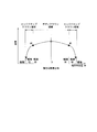
- the value of the body crown is a value obtained by subtracting the plate thickness W1 at the width direction position W1 from the plate thickness ⁇ at the width direction position 0 (width direction center) in FIG.
- the value of the edge drop crown is a value obtained by subtracting the plate thickness (plate thickness indicated by x) at the width direction position W2 from the plate thickness W1 in FIG.
- Patent Document 1 The technique of Patent Document 1 is known as a technique that meets such a demand.
- a roll shift type rolling mill is disposed on the upstream side of the continuous rolling equipment, and plate crown control (body crown control) or edge drop control (edge drop crown control) is performed. Further, a roll shift rolling mill is disposed on the downstream side, and roll wear dispersion and heat crown control are performed by cycle shifting the roll.
- the sheet thickness distribution control in the width direction is performed while performing sheet width schedule free rolling.
- mold roll shift rolling mill shown by FIG. 2 of patent document 1 is used as a rolling mill which performs edge drop control. Further, as a rolling mill for performing plate crown control, a roll shift type shown in FIG. 1 of Patent Document 1 or a system for shifting an S-shaped roll shown in FIG. 3 is adopted.
- the characteristics of the plate crown differ between the body crown portion which is the central portion in the width direction of the strip and the edge drop crown portion which is the end portion in the width direction of the strip.
- Non-Patent Document 1 when viewed from the final product as shown in FIG. 5 (Fig. 5), the body crown portion, which is the central portion in the width direction, is greatly influenced by the front stand, It can be seen that an edge drop crown portion is greatly influenced by the rear stage stand. That is, if the rolling mill that controls the body crown portion and the rolling mill that controls the edge drop crown portion are arranged in the same group, the effect of crown control is reduced.
- the present invention has been made in view of the above circumstances, and an object of the present invention is to provide a continuous rolling facility that can perform both body crown control and edge drop crown control satisfactorily.
- the continuous rolling facility of the present invention is a continuous rolling facility for continuously rolling a plate material by arranging rolling mills in a plurality of stages, and a body crown portion of the sheet material is provided on the front side of the rolling mills arranged in a plurality of stages.
- a first roll shift rolling mill to be controlled is disposed, and a second roll shift rolling mill for controlling the edge drop crown portion of the plate material is disposed on the rear stage side.
- the second roll shift rolling mill has an upper roll in which an inflection point at which the roll diameter changes along the roll axis direction and the increase / decrease direction of the roll diameter reverses is formed in an end region in the roll axis direction.
- a lower roll, and the upper roll and the lower roll have a shift roll having a roll curve that is point-symmetric with respect to the midpoint of the line connecting the axial centers of the individual rolls and is complementary to each other. ing.
- the first roll shift type rolling mill has an inflection point at which the roll diameter changes along the roll axis direction and the increase / decrease direction of the roll diameter is reversed in the roll axis direction.
- Two upper rolls and two lower rolls are formed on the outer sides of the center, and the upper roll and the lower roll are point-symmetric with respect to the midpoint of the line connecting the axial centers of the individual rolls. It is preferable to include shift rollers having roll curves that are complementary to each other.
- a third roll shift type rolling mill for performing an oscillation roll shift is disposed further downstream of the second roll shift type rolling mill.
- the first roll shift rolling mill for controlling the body crown portion of the plate material is arranged on the front stage side among the rolling machines arranged in a plurality of stages, and the plate material is arranged on the rear stage side.
- the second roll shift rolling mill for controlling the edge drop crown portion of the present invention is arranged, as shown in Non-Patent Document 1, the body crown portion is controlled on the front stage side, which has a greater influence, and the edge drop crown is controlled.
- the body crown part is controlled on the front side and the edge drop crown part is controlled on the back side, the body crown at the center in the width direction of the strip is improved by the body crown control on the front side, but the edge drop crown Can hardly be controlled, and an edge drop crown exists to some extent at the widthwise end of the strip.
- edge drop control is started in a state where a certain amount of edge drop crown is present on the band plate on the incoming plate side.
- the second roll shift rolling mill is not a single taper roll shift rolling mill, but an inflection point at which the roll diameter changes in the roll axis direction and the increase / decrease direction of the roll diameter is reversed.
- FIG. 1 is a side sectional view showing a schematic configuration of an embodiment of a continuous rolling facility according to the present invention, and reference numeral 1 in FIG. 1 is a continuous rolling facility.
- This continuous rolling equipment 1 has a stand tandem structure of rolling mill rows F1 to F6 in which rolling mills are arranged in a plurality of stages, and a strip (plate material) 2 is continuously arranged from the left side to the right side in FIG. Run and roll.
- the first roll-shift type rolling mill 10 for controlling the body crown portion of the strip 2 is disposed on the front stage side of the six stand tandems, that is, on the rolling mill rows F1 to F3.
- the second roll shift rolling mill 20 that controls the edge drop crown portion of the strip 2 is arranged.
- the 3rd roll shift type rolling mill 30 which performs an oscillation roll shift is arrange
- a plate thickness distribution detecting device 40 for detecting a plate thickness distribution in the width direction of the strip 2 after rolling is disposed on the downstream side of the rolling mill rows F1 to F6.
- the plate thickness distribution detecting device 40 detects the plate thickness distribution of the strip 2 exiting the rolling mill rows F1 to F6 and outputs the detection result to the control device 50.
- the control device 50 calculates a difference between the detection result sent from the plate thickness distribution detection device 40 and a desired value (set value) that is set and input in advance, and based on the calculated result, the rolling mill of each stand Each of the shift set values is fed back as a control signal to control the thickness distribution of the strip 2 to a desired value (set value).
- the body crown portion and the edge drop crown portion of the band plate are regions of the plate thickness distribution in the width direction as shown in FIG. That is, for the thin crown, as shown in FIG. 2, the region from the width end to the width end W1 is referred to as an edge drop crown portion (edge drop crown region), and one side from the width end W1 to the other side.
- the region between the width ends W1 is called a body crown portion (body crown region).
- W1 and W2 are lengths arbitrarily set by researchers or the like. For example, as W1, 100 mm is adopted, or 125 mm or 75 mm is adopted. As W2, 25 mm and other lengths are adopted. W2 is a value used for calculating the representative edge drop region crown.
- the first roll shift type rolling mill 10 constituting the rolling mill rows F1 to F3 includes a shift roll 11 composed of an upper roll 11a and a lower roll 11b arranged vertically, an upper roll 11a, Holding rollers 12 and 12 are provided to support the lower roll 11b from above or below.
- the upper roll 11a and the lower roll 11b are work rolls that are rolled through the strip 2 between them.
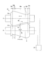
- the first roll shift rolling mill 10 includes a roll shift device 13 that shifts the upper roll 11a and the lower roll 11b in axial directions opposite to each other (the roll axis P direction) as shown in FIG. It has been.
- the upper roll 11a and the lower roll 11b have inflection points at which the roll diameter changes and the increase / decrease direction of the roll diameter reverses outside the centers Pa and Pb in the axis P direction of the individual rolls 11a and 11b.
- the respective roll curves are point-symmetric with respect to the midpoint Pc of the line L connecting the axial centers Pa and Pb of the individual rolls 11a and 11b between the upper roll 11a and the lower roll 11b. And it arrange
- the roll curves of the upper roll 11a and the lower roll 11b are each formed with five regions from the first region 14a to the fifth region 14e.
- the first region 14a the roll diameter changes from one axial direction to the other in the axial central portion of the roll.
- the second region 14b is outside the first region 14a, and the direction of change (increase / decrease direction) of the roll diameter is reversed. Therefore, the first inflection point H1 is formed.
- the third region 14c is outside the second region 14b, and the roll diameter changes in a direction opposite to the direction of change of the roll diameter in the first region 14a.
- the fourth region 14d is outside the third region 14c, and the change direction (increase / decrease direction) of the roll diameter is reversed. Therefore, the second inflection point H2 is formed.
- the fifth region 14e is outside the fourth region 14d, and the roll diameter changes in a direction opposite to the direction of change of the roll diameter in the third region 14c.
- the upper roll 11a and the lower roll 11b are arranged so as to be complementary to each other.
- This complementary shape refers to a state in which the concave and convex shapes are engaged with each other as shown in FIG. .
- the upper roll 11a and the lower roll 11b are uniform in the roll axis P direction at the basic position (initial position). Gaps are formed.
- the shift roll 11 of the present embodiment has a greater control capability of the body crown portion because the roll curve changes more on the center side in the roll axis P direction as described above.
- the result of synthesizing the shape displacement due to the roll shift itself and the displacement due to the bending of the roll can be made a gentle displacement, and the change of the crown due to the roll shift can be increased. Therefore, by having such a roll curve, the shift roll 11 has a large crown changing ability by the roll shift, and the body crown control can be performed better.
- the second roll shift rolling mill 20 constituting the rolling mill rows F4 and F5 includes a shift roll 21 composed of an upper roll 21a and a lower roll 21a arranged above and below, an upper roll 21a, a lower roll Holding rolls 22 and 22 that support the roll 21b from above or below.
- the upper roll 21a and the lower roll 21b are work rolls that are rolled through the strip 2 between them.
- the second roll shift rolling mill 20 includes a roll shift device 23 that shifts the upper roll 21a and the lower roll 21b in axial directions opposite to each other (the roll axis P direction) as shown in FIG. It has been.
- the upper roll 21a and the lower roll 21b have inflection points in the end region in the roll axis P direction where the roll diameter changes and the increase / decrease direction of the roll diameter is reversed.
- the respective roll curves are point-symmetric with respect to the midpoint Pc of the line L connecting the axial centers Pa and Pb of the individual rolls 21a and 21b between the upper roll 21a and the lower roll 21b.
- the complementary shape here also refers to a state in which the concavo-convex shapes are engaged with each other, as in the case of the first roll shift rolling mill 10 shown in FIG.
- the roll curves of the upper roll 21a and the lower roll 21b are each formed with three regions from the first region 24a to the third region 24c.
- the first region 24a the roll diameter changes from one axial direction to the other in the axial central portion of the roll.
- the second region 24b is outside the first region 24a, and the direction of change (increase / decrease direction) of the roll diameter is reversed. Therefore, the inflection point H is formed.
- the third region 24c is outside the second region 24b, and the roll diameter is changed in a direction opposite to the change direction of the roll diameter of the first region 14a.
- the inflection point H is formed in the end region of each roll 21a, 21b in the roll axis P direction. Specifically, since the vicinity of the inflection point H is a place that mainly controls the edge drop crown, the inflection point H is formed at a position of, for example, 100 mm or less from the edge of each roll 21a, 21b.
- the second roll shift rolling mill 20 has a single taper. Once the strip 2 is meandering, as in the case of a roll-type rolling mill, the meandering does not become larger and the meandering is less likely to occur. Further, since the edge drop can be adjusted to plus or minus, the control ability of the edge drop crown portion is increased.
- the body crown portion is controlled by the first roll shift rolling mill 10 on the front stage side
- the edge drop crown portion is controlled by the second roll shift rolling mill 20 on the rear stage side. Therefore, although the body crown at the center in the width direction of the strip 2 is improved by the body crown control by the first roll shift rolling mill 10 on the front stage side, the edge drop crown is reduced in the first roll shift rolling mill 10. Almost no control can be performed, so that an edge drop crown exists to some extent at the end of the strip 2 in the width direction. As a result, when edge drop control is performed by the second roll shift rolling mill 20 on the rear stage side, a certain amount of edge drop crown is present on the strip 2 on the incoming plate side. That is, in the second roll shift rolling mill 20, edge drop control is started on the strip 2 in a state where the edge drop crown is present.
- the shape of the roll corresponding to the edge drop region is preferably a shape that can change the edge drop to plus or minus.
- the thickness of the strip 2 is geometrically increased toward the width end. It is difficult to change the drop crown with a positive value.
- the inflection point H where the roll diameter changes in the roll axis direction and the increase / decrease direction of the roll diameter reverses in the end region in the roll axis direction.
- the upper roll 21a and the lower roll 21b are formed, and the upper roll 21a and the lower roll 21b are connected to the midpoint Pc of the line L connecting the axial centers Pa and Pb of the individual rolls 21a and 21b. Since the shift roll 21 having point curves and complementary roll curves is provided, the edge drop can be made positive or negative as described above.
- the edge drop crown control in order to control the edge drop formed by the upstream body crown control, it is particularly effective to perform the edge drop crown control by the second roll shift rolling mill 20 of the present embodiment. Moreover, in this 2nd roll shift type rolling mill 20, there is almost no problem of the meandering of the strip 2 like a single taper type roll shift rolling mill, and therefore the edge drop crown control can be performed satisfactorily.
- the 3rd roll shift type rolling mill 30 which comprises the rolling mill row
- the upper roll 31a and the lower roll 31b are work rolls that are rolled through the strip 2 between them.
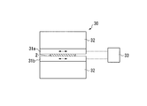
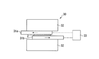
- the third roll shift rolling mill 30 is configured to shift the upper roll 31a and the lower roll 31b in axial directions opposite to each other (roll axis P direction) as shown in FIGS. 5A and 5B. 33 is provided so that an oscillation roll shift can be performed.
- the upper roll 31a and the lower roll 31b are in a state in which the upper roll 31a and the lower roll 31b face each other almost as shown in FIG. 5A and the upper roll 31b as shown in FIG. 5B.
- the state where one end portion of 31a and the other end portion of lower roll 31b are shifted in the opposite direction is cycle-shifted.
- the strip 2 is passed through the first rolling mill F1 (10) of the rolling mill rows F1 to F6. Pass to the sixth rolling mill F6 (30). Then, after passing through the rolling mill rows F1 to F6, the thickness distribution in the width direction of the strip 2 after rolling is detected by the plate thickness distribution detecting device 40 arranged on the downstream side of the rolling mill rows F1 to F6.
- the first roll shift rolling mill 10 is used as the rolling mill in the rolling mill rows F1 to F3 on the upstream side in particular, so that these first rolls
- the body crown control can be performed more favorably by the shift type rolling mill 10.
- the second roll shift rolling mill 20 is used as the rolling mill in the rear rolling mill rows F4 and F5
- the edge drop crown control is performed more favorably by the second roll shift rolling mill 20.
- the third roll shift rolling mill 30 is used as the rolling mill in the rolling mill row F6 on the rear stage side of the second roll shift rolling mill 20, it is possible to perform roll wear dispersion and heat crown control. it can.
- the plate thickness distribution detection device 40 outputs the detection result of the plate thickness distribution of the strip 2 exiting the rolling mill rows F1 to F6 to the control device 50, and the control device 50 supplies the shift set values to the respective rolling mills. Therefore, the thickness distribution of the strip 2 can be controlled to a desired value (set value) by adjusting the roll shift amount based on the shift set value in each rolling mill.
- the body crown portion is controlled on the front stage side having a larger influence, and the edge drop crown portion control is performed on the rear stage side having a larger influence. Both body crown control and edge drop crown control can be performed satisfactorily.
- the second roll shift type rolling mill 20 for controlling the edge drop crown portion not the single taper type roll shift rolling mill, but an upper roll 21a in which an inflection point H is formed in the end region in the roll axis direction; Since the thing provided with the shift roll 21 provided with the lower roll 21b is used, the edge drop control can be satisfactorily performed even for the edge drop crown already attached.
- the first roll shift type rolling mill 10 for controlling the body crown portion two inflection points H1 and H2 are formed on the outer sides from the center in the roll axis P direction, whereby the upper roll 11a, Since the lower roll 11b is provided with the shift roll 11 having a undulating shape, the deformation of the upper roll 11a and the lower roll 11b is concentrated on the center side in the roll axis P direction.
- the control effect can be increased at the body crown.
- the present invention is not limited to the above-described embodiment, and various modifications can be made without departing from the gist of the present invention.
- the third roll shift rolling mill 30 that performs the oscillation roll shift is disposed on the further rear side of the second roll shift rolling mill 20, but in recent years, a hard high-speed roll is used. In many cases, the oscillation roll shift is not performed. Therefore, instead of the third roll shift rolling mill 30, a second roll shift rolling mill 20 that controls the edge drop crown portion may be disposed as a rolling mill in the rolling mill row F6.
- the first roll shift rolling mill 10 that controls the body crown portion may be arranged and used as the rolling mill of the rolling mill row F4 in place of the second roll shift rolling mill 20. it can.
- the third roll shift rolling mill 30 or the second roll shift rolling mill 20 may be used as the rolling mill of the rolling mill row F6. Therefore, as a rolling mill of this rolling mill row F6, rolling that is compatible between the shift roll 31 for the third roll shift rolling mill 30 and the shift roll 21 for the second roll shift rolling mill 20 is possible. It is preferable to use a machine. Similarly, as the rolling mill in the rolling mill row F4, the shift roll 21 for the second roll shift rolling mill 20 and the shift roll 11 for the first roll shift rolling mill 10 are compatible. It is preferable to use a rolling mill.
- a centrally symmetrical parabolic roll crown shape is given to the roll for the purpose of compensating for the entire deflection of the roll, but the shift of the roll shift rolling mill according to the present invention is provided.
- the roll shape may also be a shape obtained by adding this deflection compensation roll curve.
Landscapes
- Engineering & Computer Science (AREA)
- Mechanical Engineering (AREA)
- Reduction Rolling/Reduction Stand/Operation Of Reduction Machine (AREA)
- Control Of Metal Rolling (AREA)
Description
本発明は、連続圧延設備に関する。
本願は、2012年9月20日に日本に出願された特願2012-206572号に基づき優先権を主張し、その内容をここに援用する。
本願は、2012年9月20日に日本に出願された特願2012-206572号に基づき優先権を主張し、その内容をここに援用する。
従来、連続圧延設備として、複数段に配置された圧延機を備え、圧延機に帯板を通すことで帯板を連続的に圧延し、薄くする設備が知られている。このような設備では、帯板の幅方向の板厚分布、すなわち帯板の幅方向中央部のボディクラウン(板クラウン)、もしくは帯板の幅方向端部のエッジドロップクラウンを所望の分布形状にすることが要望されている。なお、ボディクラウンの値は、後述する図2において、幅方向位置が0(幅方向中央部)での板厚Δから、幅方向位置がW1での板厚W1を差し引いた値である。また、エッジドロップクラウンの値は、図2において、板厚W1から幅方向位置がW2での板厚(×印で示す板厚)を差し引いた値である。
このような要望に応える技術として、特許文献1の技術が知られている。この特許文献1の技術では、連続圧延設備の上流側にロールシフト式圧延機を配置し、板クラウン制御(ボディクラウン制御)もしくはエッジドロップ制御(エッジドロップクラウン制御)を行っている。また、下流側にはロールシフト式圧延機を配置し、ロールをサイクルシフトすることにより、ロールの摩耗分散やヒートクラウン制御を行っている。これにより、この特許文献1の技術では、板幅スケジュールフリー圧延を行いつつ、幅方向の板厚み分布の制御(板クラウン制御及びエッジドロップ制御)を行っている。
また、この特許文献1では、エッジドロップ制御を行う圧延機として、特許文献1の第2図に示される片テーパ式ロールシフト圧延機を用いている。さらに、板クラウン制御を行う圧延機として、特許文献1の第1図に示されるロールシフト式、あるいは第3図に示されるS字形のロールをシフトする方式を採用している。
熱間圧延材の幅方向のクラウン比率遺伝特性を活用したクラウン制御の検討 「塑性と加工(日本塑性加工学会誌)」 第38巻 第433号(1997-2)p.165-170
ところで、板クラウンは帯板の幅方向中央部であるボディクラウン部と、帯板の幅方向端部であるエッジドロップクラウン部とで特性が異なる。
非特許文献1によれば、その第5図(Fig.5)に示されるように最終製品から見ると、幅方向中央部であるボディクラウン部は前段スタンドの影響が大きく、幅方向端部であるエッジドロップクラウン部は後段スタンドの影響が大きいことが分かる。すなわち、ボディクラウン部の制御を行う圧延機とエッジドロップクラウン部の制御を行う圧延機とは、これらを同一グループ内に配置するとクラウン制御の効果が低くなる。
非特許文献1によれば、その第5図(Fig.5)に示されるように最終製品から見ると、幅方向中央部であるボディクラウン部は前段スタンドの影響が大きく、幅方向端部であるエッジドロップクラウン部は後段スタンドの影響が大きいことが分かる。すなわち、ボディクラウン部の制御を行う圧延機とエッジドロップクラウン部の制御を行う圧延機とは、これらを同一グループ内に配置するとクラウン制御の効果が低くなる。
また、特許文献1においてエッジドロップクラウン制御を行う片テーパ式ロールシフト圧延機では、圧延機のロール間を走行する帯板が横に蛇行すると、シフトロールのテーパ部での変形が増して帯板の蛇行がますます大きくなるという特性があり、エッジドロップ制御がし難い。
また、帯板を圧延する際には、圧延によって出板側のエッジドロップクラウンを正の値で変化させたい(幅端に向かって薄くしたい)場合もあるが、片テーパ式ロールシフト圧延機では、幾何学的には帯板の板厚が幅端に向かって厚くなるため、エッジドロップクラウンを正の値で変化させるのが困難である。
また、帯板を圧延する際には、圧延によって出板側のエッジドロップクラウンを正の値で変化させたい(幅端に向かって薄くしたい)場合もあるが、片テーパ式ロールシフト圧延機では、幾何学的には帯板の板厚が幅端に向かって厚くなるため、エッジドロップクラウンを正の値で変化させるのが困難である。
本発明は前記事情に鑑みてなされたもので、ボディクラウン制御とエッジドロップクラウン制御とを共に良好に行うことができるようにした、連続圧延設備を提供することを目的とする。
本発明の連続圧延設備は、圧延機を複数段に配置して板材を連続して圧延する連続圧延設備において、複数段に配置された圧延機のうちの前段側に、板材のボディクラウン部を制御する第1のロールシフト式圧延機が配置され、後段側に、板材のエッジドロップクラウン部を制御する第2のロールシフト式圧延機が配置される。また、第2のロールシフト式圧延機は、ロール軸方向に沿ってロール径が変化するとともに、このロール径の増減方向が逆転する変曲点をロール軸方向の端部領域に形成した上ロールと下ロールとを備え、かつ、これら上ロールと下ロールとが、個々のロールの軸方向の中心を結ぶ線の中点に対し点対称で互いに補完形状にあるロールカーブを有するシフトロールを備えている。
また、本発明の連続圧延設備において、第1のロールシフト式圧延機は、ロール軸方向に沿ってロール径が変化するとともに、このロール径の増減方向が逆転する変曲点をロール軸方向の中心よりそれぞれの外側に2箇所ずつ形成した上ロールと下ロールとを備え、かつ、これら上ロールと下ロールとが、個々のロールの軸方向の中心を結ぶ線の中点に対し点対称で互いに補完形状にあるロールカーブを有するシフトロールを備えて構成されていることが好ましい。
また、本発明の連続圧延設備において、第2のロールシフト式圧延機のさらに後段側に、オシレーションロールシフトを行う第3のロールシフト式圧延機が配置されていることが好ましい。
本発明の連続圧延設備によれば、複数段に配置された圧延機のうちの前段側に、板材のボディクラウン部を制御する第1のロールシフト式圧延機を配置し、後段側に、板材のエッジドロップクラウン部を制御する第2のロールシフト式圧延機を配置したので、非特許文献1に示されるようにボディクラウン部の制御をより影響が大きい前段側で行い、かつ、エッジドロップクラウン部の制御をより影響が大きい後段側で行うことにより、ボディクラウン部の制御、エッジドロップクラウン部の制御を共に良好に行うことができる。
また、前段側でボディクラウン部を制御し、後段側でエッジドロップクラウン部を制御すると、前段側でのボディクラウン制御では帯板の幅方向中央部のボディクラウンは改善されるものの、エッジドロップクラウンはほとんど制御することができず、帯板の幅方向端部にはエッジドロップクラウンがある程度存在してしまう。その結果、後段側でのエッジドロップ制御の際には、ある程度のエッジドロップクラウンが入板側の帯板に存在した状態で、エッジドロップ制御が開始される。
しかし、本発明では、第2のロールシフト式圧延機として、片テーパ式ロールシフト圧延機ではなく、ロール軸方向にロール径が変化するとともに、このロール径の増減方向が逆転する変曲点をロール軸方向の端部領域に形成した上ロールと下ロールとを備え、かつ、これら上ロールと下ロールとが、個々のロールの軸方向の中心を結ぶ線の中点に対し点対称で互いに補完形状にあるロールカーブを有するシフトロールを備えた圧延機を用いるので、既に付いているエッジドロップクラウンに対しても、そのエッジドロップ制御を良好に行うことができる。
しかし、本発明では、第2のロールシフト式圧延機として、片テーパ式ロールシフト圧延機ではなく、ロール軸方向にロール径が変化するとともに、このロール径の増減方向が逆転する変曲点をロール軸方向の端部領域に形成した上ロールと下ロールとを備え、かつ、これら上ロールと下ロールとが、個々のロールの軸方向の中心を結ぶ線の中点に対し点対称で互いに補完形状にあるロールカーブを有するシフトロールを備えた圧延機を用いるので、既に付いているエッジドロップクラウンに対しても、そのエッジドロップ制御を良好に行うことができる。
以下、図面を参照して本発明の連続圧延設備を詳しく説明する。なお、以下の説明に用いる各図面では、各部材を認識可能な大きさとするため、各部材の縮尺を適宜変更している。
図1は、本発明に係る連続圧延設備の一実施形態の概略構成を示す側断面図であり、図1中符号1は連続圧延設備である。
図1は、本発明に係る連続圧延設備の一実施形態の概略構成を示す側断面図であり、図1中符号1は連続圧延設備である。
この連続圧延設備1は、圧延機を複数段に配置してなる圧延機列F1~F6のスタンドタンデム構造を有しており、帯板(板材)2を図1中左側から右側に連続して走行させ、圧延する。そして、この6スタンドタンデムのうち前段側、すなわち圧延機列F1~F3には、帯板2のボディクラウン部を制御する第1のロールシフト式圧延機10が配置され、後段側、すなわち圧延機列F4、F5には、帯板2のエッジドロップクラウン部を制御する第2のロールシフト式圧延機20が配置されている。
また、本実施形態では、第2のロールシフト式圧延機20のさらに後段側、すなわち圧延機列F6に、オシレーションロールシフトを行う第3のロールシフト式圧延機30が配置されている。
さらに、圧延機列F1~F6の下流側には、圧延後の帯板2の幅方向の板厚分布を検出する板厚分布検出装置40が配置されている。
さらに、圧延機列F1~F6の下流側には、圧延後の帯板2の幅方向の板厚分布を検出する板厚分布検出装置40が配置されている。
板厚分布検出装置40は、圧延機列F1~F6を出た帯板2の板厚分布を検出して検出結果を制御装置50に出力する。
制御装置50は、板厚分布検出装置40から送られてきた検出結果と、予め設定され入力された所望値(設定値)とのずれを算出し、算出した結果に基づき、各スタンドの圧延機に制御信号としてそれぞれシフト設定値をフィードバックし、帯板2の板厚分布が所望値(設定値)になるように制御する。
制御装置50は、板厚分布検出装置40から送られてきた検出結果と、予め設定され入力された所望値(設定値)とのずれを算出し、算出した結果に基づき、各スタンドの圧延機に制御信号としてそれぞれシフト設定値をフィードバックし、帯板2の板厚分布が所望値(設定値)になるように制御する。
ここで、帯板(板材)のボディクラウン部、エッジドロップクラウン部とは、図2に示すように、幅方向における板厚分布の領域である。すなわち、薄板クラウンについては、図2に示すように、幅端から幅端W1までの間の領域をエッジドロップクラウン部(エッジドロップクラウン領域)と云い、一方の側の幅端W1から他方の側の幅端W1までの間の領域をボディクラウン部(ボディクラウン領域)と云う。ここで、W1、W2は研究者等によって任意に設定される長さであり、例えばW1としては、100mmが採用されたり、125mmや75mmが採用される。W2としては、25mmや、その他の長さが採用される。なお、W2は、代表エッジドロップ領域クラウンの算出に用いられる値である。
圧延機列F1~F3を構成する第1のロールシフト式圧延機10は、図1に示すように、上下に配置された上ロール11a及び下ロール11bからなるシフトロール11と、上ロール11a、下ロール11bをその上方、あるいは下方から支持する控ロール12、12とを備えている。
上ロール11a、下ロール11bは、これらの間に帯板2を通して圧延する作業ロールである。第1のロールシフト式圧延機10には、これら上ロール11a、下ロール11bを、図3に示すように互いに反対方向の軸方向(ロール軸P方向)にシフトさせる、ロールシフト装置13が備えられている。
また、上ロール11a、下ロール11bは、ロール径が変化するとともに、ロール径の増減方向が逆転する変曲点を、個々のロール11a、11bの軸P方向の中心Pa、Pbよりそれぞれの外側に2箇所ずつ形成している。そして、シフトロール11は、それぞれのロールカーブが、上ロール11aと下ロール11bとで、個々のロール11a、11bの軸方向の中心Pa、Pbを結ぶ線Lの中点Pcに対し点対称となり、かつ、互いに補完形状となるように配置されている。
すなわち、上ロール11a、下ロール11bのロールカーブは、いずれも第1領域14aから第5領域14eまでの五つの領域を有して形成されている。第1領域14aは、ロールの軸方向中心部においてロール径が軸方向の一方から他方に向かって変化している。
第2領域14bは、第1領域14aの外側にあり、ロール径の変化方向(増減方向)が逆転している。したがって、第1の変曲点H1を形成している。第3領域14cは、第2領域14bの外側にあってロール径が第1領域14aのロール径の変化方向と反対の方向に変化している。第4領域14dは、第3領域14cの外側にあってロール径の変化方向(増減方向)が逆転している。したがって、第2の変曲点H2を形成している。第5領域14eは、第4領域14dの外側にあってロール径が第3領域14cのロール径の変化方向と反対の方向に変化している。
第2領域14bは、第1領域14aの外側にあり、ロール径の変化方向(増減方向)が逆転している。したがって、第1の変曲点H1を形成している。第3領域14cは、第2領域14bの外側にあってロール径が第1領域14aのロール径の変化方向と反対の方向に変化している。第4領域14dは、第3領域14cの外側にあってロール径の変化方向(増減方向)が逆転している。したがって、第2の変曲点H2を形成している。第5領域14eは、第4領域14dの外側にあってロール径が第3領域14cのロール径の変化方向と反対の方向に変化している。
なお、上ロール11aと下ロール11bとは互いに補完形状となるように配置されている、としているが、この補完形状とは、図3に示したように互いの凹凸形状が噛み合った状態を云う。このように凹凸形状が噛み合った状態で上ロール11aと下ロール11bとが配置されることにより、基本位置(初期位置)では上ロール11aと下ロール11bとの間が、ロール軸P方向において均一な隙間を形成している。
上ロール11a、下ロール11bのロールカーブ形状として、ロール軸P方向の中心よりそれぞれの外側に2箇所ずつ変曲点H1、H2を形成し、これによって上ロール11a、下ロール11bを起伏の多い形状にしている。そのため、この第1のロールシフト式圧延機10では、ロール軸P方向の中心側にて変形が集中する。したがって、板クラウンの制御効果を、ボディクラウン部でより大きくすることができる。特に、変曲点H1、H2をよりロール軸P方向の中心側(内側)に形成すれば、板クラウンの制御効果を、ボディクラウン部でさらに大きくすることができる。
すなわち、特許文献1の第1図や第3図に示されたシフトロールでは、板材の中心部(センター部)のみを対象とする制御としては、ロールカーブが緩やかなため、制御能力が不十分である。これに対し、本実施形態のシフトロール11は、前記したようにロール軸P方向の中心側にてロールカーブがより変化しているので、ボディクラウン部の制御能力が大きくなっている。
また、ロールシフトそのものによる形状変位と、ロールの撓みによる変位とを合成した結果をなだらかな変位とし、しかもロールシフトによるクラウンの変化を大きくすることができる。
よって、このようなロールカーブを有することにより、シフトロール11はロールシフトによるクラウン変化能力が大きくなっており、ボディクラウン制御をより良好に行うことができる。
よって、このようなロールカーブを有することにより、シフトロール11はロールシフトによるクラウン変化能力が大きくなっており、ボディクラウン制御をより良好に行うことができる。
図1に示すように圧延機列F4、F5を構成する第2のロールシフト式圧延機20は、上下に配置された上ロール21a及び下ロール21aからなるシフトロール21と、上ロール21a、下ロール21bをその上方、あるいは下方から支持する控ロール22、22とを備える。
上ロール21a、下ロール21bは、これらの間に帯板2を通して圧延する作業ロールである。第2のロールシフト式圧延機20には、これら上ロール21a、下ロール21bを、図4に示すように互いに反対方向の軸方向(ロール軸P方向)にシフトさせる、ロールシフト装置23が備えられている。
また、上ロール21a、下ロール21bは、ロール径が変化するとともに、ロール径の増減方向が逆転する変曲点を、ロール軸P方向の端部領域に形成している。そして、シフトロール21は、それぞれのロールカーブが、上ロール21aと下ロール21bとで、個々のロール21a、21bの軸方向の中心Pa、Pbを結ぶ線Lの中点Pcに対し点対称となり、かつ、互いに補完形状となるように配置されている。なお、ここで云う補完形状も、図3に示した第1のロールシフト式圧延機10の場合と同様に、互いの凹凸形状が噛み合った状態を云う。
図4に示すように上ロール21a、下ロール21bのロールカーブは、いずれも第1領域24aから第3領域24cまでの三つの領域を有して形成されている。第1の領域24aは、ロールの軸方向中心部においてロール径が軸方向の一方から他方に向かって変化している。第2領域24bは、第1領域24aの外側にあり、ロール径の変化方向(増減方向)が逆転している。したがって、変曲点Hを形成している。第3領域24cは、第2領域24bの外側にあってロール径が第1領域14aのロール径の変化方向と反対の方向に変化している。
ここで、変曲点Hは各ロール21a、21bのロール軸P方向の端部領域に形成されている。具体的には、この変曲点Hの近傍が、主にエッジドロップクラウンの制御をなす箇所となるため、変曲点Hは各ロール21a、21bの端縁から例えば100mm以下の位置に形成される。
このように上ロール21a、下ロール21bのロールカーブ形状として、ロール軸P方向の端部領域に変曲点Hを形成しているので、この第2のロールシフト式圧延機20は、片テーパ式ロールシフト圧延機のように帯板2が一旦蛇行するとこの蛇行がますます大きくなることがなく、蛇行を起こしにくくなっている。また、エッジドロップをプラスにもマイナスにも調整できるので、エッジドロップクラウン部の制御能力が大きくなっている。
すなわち、本実施形態では、前段側で第1のロールシフト式圧延機10によってボディクラウン部を制御し、後段側で第2のロールシフト式圧延機20によってエッジドロップクラウン部を制御している。したがって、前段側の第1のロールシフト式圧延機10によるボディクラウン制御によって帯板2の幅方向中央部のボディクラウンは改善されるものの、第1のロールシフト式圧延機10ではエッジドロップクラウンはほとんど制御することができず、そのため、帯板2の幅方向端部にはエッジドロップクラウンがある程度存在してしまう。その結果、後段側の第2のロールシフト式圧延機20によってエッジドロップ制御を行う際には、入板側の帯板2にある程度のエッジドロップクラウンが存在した状態となっている。すなわち、第2のロールシフト式圧延機20では、エッジドロップクラウンが存在した状態の帯板2に対して、エッジドロップ制御を開始する。
圧延時には、帯板2の平坦度を維持するため、帯板2の入板側、出板側でのクラウンの比率を大きく変化させないことが望ましいとされている。したがって、入帯板2側に存在しているエッジドロップをいきなりゼロにすることは平坦度の維持の点から好ましくなく、エッジドロップ制御プロセスでは、徐々にエッジドロップを小さくしていくことが必要である。よって、エッジドロップ領域(エッジドロップクラウン部)に対応するロールの形状は、エッジドロップを、プラスにもマイナスにも変化させることができる形状が望ましい。
ところが、特許文献1に示された片テーパ式ロールシフト圧延機のような片テーパロールシフト方式の制御では、幾何学的には帯板2の板厚が幅端に向かって厚くなるため、エッジドロップクラウンを正の値で変化させるのが困難である。
これに対し、本実施形態の第2のロールシフト式圧延機20では、ロール軸方向にロール径が変化するとともにロール径の増減方向が逆転する変曲点Hをロール軸方向の端部領域に形成した上ロール21aと下ロール21bとを備え、かつ、これら上ロール21aと下ロール21bとが、個々のロール21a、21bの軸方向の中心Pa、Pbを結ぶ線Lの中点Pcに対し点対称で互いに補完形状にあるロールカーブを有するシフトロール21を備えているので、前記したようにエッジドロップをプラスにもマイナスにもすることができる。
これに対し、本実施形態の第2のロールシフト式圧延機20では、ロール軸方向にロール径が変化するとともにロール径の増減方向が逆転する変曲点Hをロール軸方向の端部領域に形成した上ロール21aと下ロール21bとを備え、かつ、これら上ロール21aと下ロール21bとが、個々のロール21a、21bの軸方向の中心Pa、Pbを結ぶ線Lの中点Pcに対し点対称で互いに補完形状にあるロールカーブを有するシフトロール21を備えているので、前記したようにエッジドロップをプラスにもマイナスにもすることができる。
したがって、上流のボディクラウン制御で形成されたエッジドロップを制御するためには、本実施形態の第2のロールシフト式圧延機20でエッジドロップクラウン制御を行うことが特に有効となる。
また、この第2のロールシフト式圧延機20では、片テーパ式ロールシフト圧延機のような帯板2の蛇行の問題もほとんど無く、したがってエッジドロップクラウン制御を良好に行うことができる。
また、この第2のロールシフト式圧延機20では、片テーパ式ロールシフト圧延機のような帯板2の蛇行の問題もほとんど無く、したがってエッジドロップクラウン制御を良好に行うことができる。
圧延機列F6を構成する第3のロールシフト式圧延機30は、図1に示すように、上下に配置された上ロール31a及び下ロール31aからなるシフトロール31と、上ロール31a、下ロール31bをその上方、あるいは下方から支持する控ロール32、32とを備えて構成されている。
上ロール31a、下ロール31bは、これらの間に帯板2を通して圧延する作業ロールである。第3のロールシフト式圧延機30には、これら上ロール31a、下ロール31bを、図5A及び図5Bに示すように互いに反対方向の軸方向(ロール軸P方向)にシフトさせる、ロールシフト装置33が備えられており、これによってオシレーションロールシフトが行われるようになっている。
すなわち、このようなロールシフト装置33によって上ロール31a、下ロール31bは、図5Aに示すように上ロール31aと下ロール31bとがほぼ全面で対向する状態と、図5Bに示すように上ロール31aの一方の端部側と下ロール31bの他方の端部側とが逆方向にずれる状態とをサイクルシフトするようになっている。
これにより、第3のロールシフト式圧延機30では、ロールの摩耗分散やヒートクラウン制御を行うことができる。
これにより、第3のロールシフト式圧延機30では、ロールの摩耗分散やヒートクラウン制御を行うことができる。
このような構成からなる連続圧延設備1によって帯板2を連続圧延するには、まず、帯板2を圧延機列F1~F6の一段目の圧延機F1(10)に通し、以下、順番に六段目の圧延機F6(30)まで通す。そして、圧延機列F1~F6を通した後、圧延機列F1~F6の下流側に配置した板厚分布検出装置40によって圧延後の帯板2の幅方向の板厚分布を検出する。
このように圧延機列F1~F6を順番に通すことで、特に前段側の圧延機列F1~F3では圧延機として第1のロールシフト式圧延機10を用いているので、これら第1のロールシフト式圧延機10によってボディクラウン制御をより良好に行うことができる。また、後段側の圧延機列F4、F5では圧延機として第2のロールシフト式圧延機20を用いているので、これら第2のロールシフト式圧延機20によってエッジドロップクラウン制御をより良好に行うことができる。さらに、第2のロールシフト式圧延機20の後段側の圧延機列F6では圧延機として第3のロールシフト式圧延機30を用いているので、ロールの摩耗分散やヒートクラウン制御を行うことができる。
また、板厚分布検出装置40によって圧延機列F1~F6を出た帯板2の板厚分布の検出結果を制御装置50に出力し、制御装置50によって各スタンドの圧延機にそれぞれシフト設定値をフィードバックするので、各圧延機でそれぞれシフト設定値に基づいてロールシフト量を調整することにより、帯板2の板厚分布を所望値(設定値)になるように制御することができる。
このように、本実施形態の連続圧延設備1によれば、ボディクラウン部の制御をより影響が大きい前段側で行い、エッジドロップクラウン部の制御をより影響が大きい後段側で行うようにしたので、ボディクラウン部の制御、エッジドロップクラウン部の制御を共に良好に行うことができる。
また、エッジドロップクラウン部の制御を行う第2のロールシフト式圧延機20として、片テーパ式ロールシフト圧延機ではなく、変曲点Hをロール軸方向の端部領域に形成した上ロール21aと下ロール21bとを備えるシフトロール21を備えたものを用いるので、既に付いているエッジドロップクラウンに対しても、そのエッジドロップ制御を良好に行うことができる。
また、エッジドロップクラウン部の制御を行う第2のロールシフト式圧延機20として、片テーパ式ロールシフト圧延機ではなく、変曲点Hをロール軸方向の端部領域に形成した上ロール21aと下ロール21bとを備えるシフトロール21を備えたものを用いるので、既に付いているエッジドロップクラウンに対しても、そのエッジドロップ制御を良好に行うことができる。
また、ボディクラウン部の制御を行う第1のロールシフト式圧延機10として、ロール軸P方向の中心よりそれぞれの外側に2箇所ずつ変曲点H1、H2を形成し、これによって上ロール11a、下ロール11bを起伏の多い形状にしたシフトロール11を備えたものを用いるので、上ロール11a、下ロール11bがロール軸P方向の中心側にて変形が集中していることにより、板クラウンの制御効果を、ボディクラウン部でより大きくすることができる。
また、第2のロールシフト式圧延機20のさらに後段側に、オシレーションロールシフトを行う第3のロールシフト式圧延機30を配置しているので、この第3のロールシフト式圧延機30によってロールの摩耗分散やヒートクラウン制御を行うことができる。
なお、本発明は前記実施形態に限定されることなく、本発明の主旨を逸脱しない範囲で種々の変更が可能である。
例えば、前記実施形態では第2のロールシフト式圧延機20のさらに後段側に、オシレーションロールシフトを行う第3のロールシフト式圧延機30を配置したが、近年では硬いハイスロールが使われることもあり、オシレーションロールシフトを行わない場合も多い。そのため、圧延機列F6の圧延機として、第3のロールシフト式圧延機30に代えてエッジドロップクラウン部を制御する第2のロールシフト式圧延機20を配置してもよい。
例えば、前記実施形態では第2のロールシフト式圧延機20のさらに後段側に、オシレーションロールシフトを行う第3のロールシフト式圧延機30を配置したが、近年では硬いハイスロールが使われることもあり、オシレーションロールシフトを行わない場合も多い。そのため、圧延機列F6の圧延機として、第3のロールシフト式圧延機30に代えてエッジドロップクラウン部を制御する第2のロールシフト式圧延機20を配置してもよい。
また、その場合には、圧延機列F4の圧延機として、第2のロールシフト式圧延機20に代えてボディクラウン部を制御する第1のロールシフト式圧延機10を配置し、用いることもできる。
また、このように本発明の連続圧延設備では、圧延機列F6の圧延機として第3のロールシフト式圧延機30を用いる場合と、第2のロールシフト式圧延機20を用いる場合がある。そのため、この圧延機列F6の圧延機として、第3のロールシフト式圧延機30用のシフトロール31と第2のロールシフト式圧延機20用のシフトロール21との間で互換性のある圧延機を用いるのが好ましい。
同様に、圧延機列F4の圧延機としても、第2のロールシフト式圧延機20用のシフトロール21と第1のロールシフト式圧延機10用のシフトロール11との間で互換性のある圧延機を用いるのが好ましい。
同様に、圧延機列F4の圧延機としても、第2のロールシフト式圧延機20用のシフトロール21と第1のロールシフト式圧延機10用のシフトロール11との間で互換性のある圧延機を用いるのが好ましい。
また、一般に非シフトの圧延機では、ロールの全体たわみを補償する目的で、ロールに中心対称の放物型のロールクラウン形状を付与しているが、本発明に係るロールシフト式圧延機のシフトロール形状も、このたわみ補償のロールカーブを加算した形状としてもよい。
また、前記実施形態では、本発明の連続圧延設備を6スタンドタンデムである設備について適用した場合について説明したが、本発明はこれに限定されることなく、例えば7スタンドタンデムである設備についても適用可能である。
ボディクラウン制御とエッジドロップクラウン制御とを共に良好に行うことができるようにした、連続圧延設備の提供が可能となる。
1 連続圧延設備、
2 帯板(板材)、
10 第1のロールシフト式圧延機、
11、21、31 シフトロール、
11a、21a、31a 上ロール、
11b、21b、31b 下ロール、
20 第2のロールシフト式圧延機、
30 第3のロールシフト式圧延機、
40 板厚分布検出装置、
50 制御装置、
P ロール軸、
Pa 上ロールの軸方向の中心
Pb 下ロールの軸方向の中心
L 上ロールの軸方向の中心と下ロールの軸方向の中心を結ぶ線
Pc 上ロールの軸方向の中心と下ロールの軸方向の中心を結ぶ線の中点
H1、H2、H…変曲点
2 帯板(板材)、
10 第1のロールシフト式圧延機、
11、21、31 シフトロール、
11a、21a、31a 上ロール、
11b、21b、31b 下ロール、
20 第2のロールシフト式圧延機、
30 第3のロールシフト式圧延機、
40 板厚分布検出装置、
50 制御装置、
P ロール軸、
Pa 上ロールの軸方向の中心
Pb 下ロールの軸方向の中心
L 上ロールの軸方向の中心と下ロールの軸方向の中心を結ぶ線
Pc 上ロールの軸方向の中心と下ロールの軸方向の中心を結ぶ線の中点
H1、H2、H…変曲点
Claims (4)
- 圧延機を複数段に配置して板材を連続して圧延する連続圧延設備において、
前記複数段に配置された圧延機のうちの前段側に、前記板材のボディクラウン部を制御する第1のロールシフト式圧延機が配置され、後段側に、前記板材のエッジドロップクラウン部を制御する第2のロールシフト式圧延機が配置され、
前記第2のロールシフト式圧延機は、ロール軸方向に沿ってロール径が変化するとともに、このロール径の増減方向が逆転する変曲点をロール軸方向の端部領域に形成した上ロールと下ロールとを備え、かつ、これら上ロールと下ロールとが、個々のロールの軸方向の中心を結ぶ線の中点に対し点対称で互いに補完形状にあるロールカーブを有するシフトロールを備えて構成されている連続圧延設備。 - 前記第1のロールシフト式圧延機は、ロール軸方向に沿ってロール径が変化するとともに、このロール径の増減方向が逆転する変曲点をロール軸方向の中心よりそれぞれの外側に2箇所ずつ形成した上ロールと下ロールとを備え、かつ、これら上ロールと下ロールとが、個々のロールの軸方向の中心を結ぶ線の中点に対し点対称で互いに補完形状にあるロールカーブを有するシフトロールを備えている請求項1記載の連続圧延設備。
- 前記第2のロールシフト式圧延機のさらに後段側に、オシレーションロールシフトを行う第3のロールシフト式圧延機が配置されている請求項1に記載の連続圧延設備。
- 前記第2のロールシフト式圧延機のさらに後段側に、オシレーションロールシフトを行う第3のロールシフト式圧延機が配置されている請求項2に記載の連続圧延設備。
Applications Claiming Priority (2)
| Application Number | Priority Date | Filing Date | Title |
|---|---|---|---|
| JP2012-206572 | 2012-09-20 | ||
| JP2012206572A JP2014061528A (ja) | 2012-09-20 | 2012-09-20 | 連続圧延設備 |
Publications (1)
| Publication Number | Publication Date |
|---|---|
| WO2014046211A1 true WO2014046211A1 (ja) | 2014-03-27 |
Family
ID=50341515
Family Applications (1)
| Application Number | Title | Priority Date | Filing Date |
|---|---|---|---|
| PCT/JP2013/075368 Ceased WO2014046211A1 (ja) | 2012-09-20 | 2013-09-19 | 連続圧延設備 |
Country Status (2)
| Country | Link |
|---|---|
| JP (1) | JP2014061528A (ja) |
| WO (1) | WO2014046211A1 (ja) |
Cited By (5)
| Publication number | Priority date | Publication date | Assignee | Title |
|---|---|---|---|---|
| CN109226281A (zh) * | 2018-10-19 | 2019-01-18 | 辽宁科技大学 | 基于无模型预估算法的硅钢边部减薄滞后控制方法 |
| CN110052497A (zh) * | 2019-04-09 | 2019-07-26 | 北京首钢股份有限公司 | 一种热连轧精轧机组成套辊形以及板形控制方法 |
| IT202100005663A1 (it) * | 2021-03-10 | 2022-09-10 | Danieli Off Mecc | Procedimento ed impianto per la produzione di prodotti laminati piani |
| CN116116486A (zh) * | 2023-04-16 | 2023-05-16 | 湖北天和机械有限公司 | 一种等角速曲线砻谷辊 |
| EP4394914A4 (en) * | 2022-10-05 | 2025-07-30 | Lg Energy Solution Ltd | ELECTRODE ROLLING DEVICE |
Families Citing this family (2)
| Publication number | Priority date | Publication date | Assignee | Title |
|---|---|---|---|---|
| JP6813101B2 (ja) * | 2017-10-31 | 2021-01-13 | 東芝三菱電機産業システム株式会社 | 圧延スタンドのロール摩耗分散方法および圧延システム |
| KR102892928B1 (ko) * | 2020-12-28 | 2025-11-27 | 주식회사 엘지에너지솔루션 | 전극 제조 장치 |
Citations (5)
| Publication number | Priority date | Publication date | Assignee | Title |
|---|---|---|---|---|
| JPH05185107A (ja) * | 1992-01-13 | 1993-07-27 | Nippon Steel Corp | 圧延機 |
| JPH07232202A (ja) * | 1994-02-25 | 1995-09-05 | Ishikawajima Harima Heavy Ind Co Ltd | 圧延機用ロールとロールシフト式圧延機 |
| JPH0824919A (ja) * | 1994-07-08 | 1996-01-30 | Ishikawajima Harima Heavy Ind Co Ltd | ロールシフトとロールベンドを併用した圧延方法と圧延機 |
| JPH11192506A (ja) * | 1998-01-06 | 1999-07-21 | Sumitomo Metal Ind Ltd | 板クラウン制御方法 |
| JP2000084601A (ja) * | 1998-09-08 | 2000-03-28 | Kawasaki Heavy Ind Ltd | 薄板の熱間圧延機 |
-
2012
- 2012-09-20 JP JP2012206572A patent/JP2014061528A/ja active Pending
-
2013
- 2013-09-19 WO PCT/JP2013/075368 patent/WO2014046211A1/ja not_active Ceased
Patent Citations (5)
| Publication number | Priority date | Publication date | Assignee | Title |
|---|---|---|---|---|
| JPH05185107A (ja) * | 1992-01-13 | 1993-07-27 | Nippon Steel Corp | 圧延機 |
| JPH07232202A (ja) * | 1994-02-25 | 1995-09-05 | Ishikawajima Harima Heavy Ind Co Ltd | 圧延機用ロールとロールシフト式圧延機 |
| JPH0824919A (ja) * | 1994-07-08 | 1996-01-30 | Ishikawajima Harima Heavy Ind Co Ltd | ロールシフトとロールベンドを併用した圧延方法と圧延機 |
| JPH11192506A (ja) * | 1998-01-06 | 1999-07-21 | Sumitomo Metal Ind Ltd | 板クラウン制御方法 |
| JP2000084601A (ja) * | 1998-09-08 | 2000-03-28 | Kawasaki Heavy Ind Ltd | 薄板の熱間圧延機 |
Cited By (8)
| Publication number | Priority date | Publication date | Assignee | Title |
|---|---|---|---|---|
| CN109226281A (zh) * | 2018-10-19 | 2019-01-18 | 辽宁科技大学 | 基于无模型预估算法的硅钢边部减薄滞后控制方法 |
| CN109226281B (zh) * | 2018-10-19 | 2020-06-30 | 辽宁科技大学 | 基于无模型预估算法的硅钢边部减薄滞后控制方法 |
| CN110052497A (zh) * | 2019-04-09 | 2019-07-26 | 北京首钢股份有限公司 | 一种热连轧精轧机组成套辊形以及板形控制方法 |
| IT202100005663A1 (it) * | 2021-03-10 | 2022-09-10 | Danieli Off Mecc | Procedimento ed impianto per la produzione di prodotti laminati piani |
| EP4056293A1 (en) * | 2021-03-10 | 2022-09-14 | Danieli & C. Officine Meccaniche S.P.A. | Method and plant for producing flat rolled products |
| WO2022190149A1 (en) * | 2021-03-10 | 2022-09-15 | Danieli & C. Officine Meccaniche S.P.A. | Method and plant for producing flat rolled products |
| EP4394914A4 (en) * | 2022-10-05 | 2025-07-30 | Lg Energy Solution Ltd | ELECTRODE ROLLING DEVICE |
| CN116116486A (zh) * | 2023-04-16 | 2023-05-16 | 湖北天和机械有限公司 | 一种等角速曲线砻谷辊 |
Also Published As
| Publication number | Publication date |
|---|---|
| JP2014061528A (ja) | 2014-04-10 |
Similar Documents
| Publication | Publication Date | Title |
|---|---|---|
| WO2014046211A1 (ja) | 連続圧延設備 | |
| US7059163B2 (en) | Roll stand comprising a crown-variable-control (CVC) roll pair | |
| CA3069981C (en) | Systems and methods for controlling flatness of a metal substrate with low pressure rolling | |
| CN107457273B (zh) | 热连轧精轧机的板形控制方法及热连轧精轧机 | |
| KR101312453B1 (ko) | 특히 금속 소재의 제품을 압연하기 위한 롤 스탠드 | |
| JP2933923B1 (ja) | 薄板の熱間圧延機 | |
| US20210170465A1 (en) | Square tube forming method and square tube forming device | |
| WO2013114909A1 (ja) | 不等辺不等厚山形鋼の製造装置及び製造方法 | |
| JP2023507649A (ja) | ローラー装置 | |
| CN102821884B (zh) | 串列式轧制设备的动作控制方法和使用该方法的热轧钢板的制造方法 | |
| KR101767825B1 (ko) | 압연롤 및 이를 포함하는 압연 시스템 | |
| WO2016175179A1 (ja) | 圧延加工装置、湾曲加工方法、湾曲加工材料 | |
| JP2000000616A (ja) | パイプ成形設備列およびパイプ成形方法 | |
| JP3698183B2 (ja) | ロールシフト式カレンダー | |
| JPWO2008123121A1 (ja) | 継目無管の製造方法及び孔型ロール | |
| JP7280505B2 (ja) | 左右フランジ厚みの異なる非対称h形鋼の製造方法 | |
| JP5821575B2 (ja) | 冷延鋼板の圧延方法および極薄鋼板の製造方法 | |
| JP4992040B2 (ja) | T形鋼の圧延方法および圧延設備 | |
| JP6064398B2 (ja) | 形鋼の曲り矯正方法 | |
| JP2021098210A (ja) | 左右フランジ厚みの異なる非対称h形鋼の製造方法 | |
| JP5343957B2 (ja) | 帯板製造設備とその方法 | |
| JP4930384B2 (ja) | H形鋼の圧延方法及び圧延装置 | |
| US20230104109A1 (en) | Production method for hat-shaped steel sheet pile | |
| JP2023100065A (ja) | ハット形鋼矢板の製造設備及び製造方法 | |
| JP5625749B2 (ja) | 圧延機および圧延方法 |
Legal Events
| Date | Code | Title | Description |
|---|---|---|---|
| 121 | Ep: the epo has been informed by wipo that ep was designated in this application |
Ref document number: 13839188 Country of ref document: EP Kind code of ref document: A1 |
|
| NENP | Non-entry into the national phase |
Ref country code: DE |
|
| 122 | Ep: pct application non-entry in european phase |
Ref document number: 13839188 Country of ref document: EP Kind code of ref document: A1 |