WO2014045969A1 - 画像記録方法 - Google Patents
画像記録方法 Download PDFInfo
- Publication number
- WO2014045969A1 WO2014045969A1 PCT/JP2013/074545 JP2013074545W WO2014045969A1 WO 2014045969 A1 WO2014045969 A1 WO 2014045969A1 JP 2013074545 W JP2013074545 W JP 2013074545W WO 2014045969 A1 WO2014045969 A1 WO 2014045969A1
- Authority
- WO
- WIPO (PCT)
- Prior art keywords
- image
- group
- paper
- meth
- ink
- Prior art date
- Legal status (The legal status is an assumption and is not a legal conclusion. Google has not performed a legal analysis and makes no representation as to the accuracy of the status listed.)
- Ceased
Links
Images


Classifications
-
- B—PERFORMING OPERATIONS; TRANSPORTING
- B41—PRINTING; LINING MACHINES; TYPEWRITERS; STAMPS
- B41J—TYPEWRITERS; SELECTIVE PRINTING MECHANISMS, i.e. MECHANISMS PRINTING OTHERWISE THAN FROM A FORME; CORRECTION OF TYPOGRAPHICAL ERRORS
- B41J2/00—Typewriters or selective printing mechanisms characterised by the printing or marking process for which they are designed
- B41J2/005—Typewriters or selective printing mechanisms characterised by the printing or marking process for which they are designed characterised by bringing liquid or particles selectively into contact with a printing material
- B41J2/01—Ink jet
-
- B—PERFORMING OPERATIONS; TRANSPORTING
- B41—PRINTING; LINING MACHINES; TYPEWRITERS; STAMPS
- B41J—TYPEWRITERS; SELECTIVE PRINTING MECHANISMS, i.e. MECHANISMS PRINTING OTHERWISE THAN FROM A FORME; CORRECTION OF TYPOGRAPHICAL ERRORS
- B41J11/00—Devices or arrangements of selective printing mechanisms, e.g. ink-jet printers or thermal printers, for supporting or handling copy material in sheet or web form
- B41J11/0015—Devices or arrangements of selective printing mechanisms, e.g. ink-jet printers or thermal printers, for supporting or handling copy material in sheet or web form for treating before, during or after printing or for uniform coating or laminating the copy material before or after printing
- B41J11/002—Curing or drying the ink on the copy materials, e.g. by heating or irradiating
- B41J11/0021—Curing or drying the ink on the copy materials, e.g. by heating or irradiating using irradiation
- B41J11/00214—Curing or drying the ink on the copy materials, e.g. by heating or irradiating using irradiation using UV radiation
-
- B—PERFORMING OPERATIONS; TRANSPORTING
- B41—PRINTING; LINING MACHINES; TYPEWRITERS; STAMPS
- B41J—TYPEWRITERS; SELECTIVE PRINTING MECHANISMS, i.e. MECHANISMS PRINTING OTHERWISE THAN FROM A FORME; CORRECTION OF TYPOGRAPHICAL ERRORS
- B41J29/00—Details of, or accessories for, typewriters or selective printing mechanisms not otherwise provided for
- B41J29/377—Cooling or ventilating arrangements
-
- B—PERFORMING OPERATIONS; TRANSPORTING
- B41—PRINTING; LINING MACHINES; TYPEWRITERS; STAMPS
- B41M—PRINTING, DUPLICATING, MARKING, OR COPYING PROCESSES; COLOUR PRINTING
- B41M5/00—Duplicating or marking methods; Sheet materials for use therein
- B41M5/0023—Digital printing methods characterised by the inks used
-
- B—PERFORMING OPERATIONS; TRANSPORTING
- B41—PRINTING; LINING MACHINES; TYPEWRITERS; STAMPS
- B41M—PRINTING, DUPLICATING, MARKING, OR COPYING PROCESSES; COLOUR PRINTING
- B41M7/00—After-treatment of prints, e.g. heating, irradiating, setting of the ink, protection of the printed stock
- B41M7/0081—After-treatment of prints, e.g. heating, irradiating, setting of the ink, protection of the printed stock using electromagnetic radiation or waves, e.g. ultraviolet radiation, electron beams
-
- C—CHEMISTRY; METALLURGY
- C09—DYES; PAINTS; POLISHES; NATURAL RESINS; ADHESIVES; COMPOSITIONS NOT OTHERWISE PROVIDED FOR; APPLICATIONS OF MATERIALS NOT OTHERWISE PROVIDED FOR
- C09D—COATING COMPOSITIONS, e.g. PAINTS, VARNISHES OR LACQUERS; FILLING PASTES; CHEMICAL PAINT OR INK REMOVERS; INKS; CORRECTING FLUIDS; WOODSTAINS; PASTES OR SOLIDS FOR COLOURING OR PRINTING; USE OF MATERIALS THEREFOR
- C09D11/00—Inks
- C09D11/02—Printing inks
- C09D11/10—Printing inks based on artificial resins
- C09D11/101—Inks specially adapted for printing processes involving curing by wave energy or particle radiation, e.g. with UV-curing following the printing
-
- C—CHEMISTRY; METALLURGY
- C09—DYES; PAINTS; POLISHES; NATURAL RESINS; ADHESIVES; COMPOSITIONS NOT OTHERWISE PROVIDED FOR; APPLICATIONS OF MATERIALS NOT OTHERWISE PROVIDED FOR
- C09D—COATING COMPOSITIONS, e.g. PAINTS, VARNISHES OR LACQUERS; FILLING PASTES; CHEMICAL PAINT OR INK REMOVERS; INKS; CORRECTING FLUIDS; WOODSTAINS; PASTES OR SOLIDS FOR COLOURING OR PRINTING; USE OF MATERIALS THEREFOR
- C09D11/00—Inks
- C09D11/02—Printing inks
- C09D11/10—Printing inks based on artificial resins
- C09D11/106—Printing inks based on artificial resins containing macromolecular compounds obtained by reactions only involving carbon-to-carbon unsaturated bonds
- C09D11/107—Printing inks based on artificial resins containing macromolecular compounds obtained by reactions only involving carbon-to-carbon unsaturated bonds from unsaturated acids or derivatives thereof
-
- C—CHEMISTRY; METALLURGY
- C09—DYES; PAINTS; POLISHES; NATURAL RESINS; ADHESIVES; COMPOSITIONS NOT OTHERWISE PROVIDED FOR; APPLICATIONS OF MATERIALS NOT OTHERWISE PROVIDED FOR
- C09D—COATING COMPOSITIONS, e.g. PAINTS, VARNISHES OR LACQUERS; FILLING PASTES; CHEMICAL PAINT OR INK REMOVERS; INKS; CORRECTING FLUIDS; WOODSTAINS; PASTES OR SOLIDS FOR COLOURING OR PRINTING; USE OF MATERIALS THEREFOR
- C09D11/00—Inks
- C09D11/30—Inkjet printing inks
-
- B—PERFORMING OPERATIONS; TRANSPORTING
- B41—PRINTING; LINING MACHINES; TYPEWRITERS; STAMPS
- B41J—TYPEWRITERS; SELECTIVE PRINTING MECHANISMS, i.e. MECHANISMS PRINTING OTHERWISE THAN FROM A FORME; CORRECTION OF TYPOGRAPHICAL ERRORS
- B41J2/00—Typewriters or selective printing mechanisms characterised by the printing or marking process for which they are designed
- B41J2/005—Typewriters or selective printing mechanisms characterised by the printing or marking process for which they are designed characterised by bringing liquid or particles selectively into contact with a printing material
- B41J2/01—Ink jet
- B41J2002/012—Ink jet with intermediate transfer member
Definitions
- the present invention relates to an image recording method using an inkjet method.
- a method of forming an image by applying ink to a desired recording medium by an ink discharge head that discharges droplet-like ink is widely used.
- image formation including a droplet discharge device, a fixing device, a cooling device for cooling the recording medium after fixing and heating, and a discharge unit for loading the recording medium
- An apparatus is disclosed, and it is said that the occurrence of stacker blocking is suppressed (see, for example, JP 2012-135984 A).
- an image recording process including an ink application process for forming an image by applying an ink composition containing a pigment and a polymer particle having a glass transition temperature of 70 ° C. or more, a drying process, and a curing process for curing the image.
- a method see, for example, JP 2011-46872 A.
- the image is cured to increase the image strength and prevent the image from being broken (blocked).
- an inkjet recording apparatus that cools immediately after irradiation with ultraviolet rays is also disclosed (see, for example, Japanese Patent Application Laid-Open No. 2006-264264).
- the appearance Since the image is a recorded matter, it is desirable that the appearance does not have an adhesive failure as described above, and that the appearance is not uneven.
- adhesion failure of the image and gloss appearing as an appearance are one of important performances in terms of image quality.
- stacker blocking is not prevented depending on the hue of the image or the amount of ink droplets, and colorants such as pigments aggregate locally. , Uneven gloss may occur.
- the present invention has been made in view of the above, and it is an object of the present invention to provide an image recording method in which occurrence of stacker blocking and gloss unevenness is prevented when a large number of recording media are stacked in a paper discharge stacking unit. .
- the drying process for drying the image, the curing process for curing the image by irradiating the dried image with active energy rays, and the image after curing are cooled so that the temperature difference before and after cooling is 15 ° C. or more.
- An image recording method includes a cooling step and a stacking step of stacking and stacking a plurality of cooled recording media.
- the cooling step is the image recording method according to ⁇ 1>, wherein the image is cooled to 60 ° C. or lower.
- the polymer particle is a copolymer particle including at least one selected from the group consisting of a structural unit having an aromatic ring structure and a structural unit having an alicyclic structure. > Is an image recording method described in the above.
- the polymer particles are particles of a copolymer including a structural unit derived from an aromatic group-containing (meth) acrylate monomer or a structural unit derived from an alicyclic (meth) acrylate. The image recording method according to any one of the above.
- the polymer particle includes at least one selected from the group consisting of a structural unit having an aromatic ring structure and a structural unit having an alicyclic structure, and has a structural unit having an aromatic ring structure and an alicyclic structure.
- the polymer particles have a copolymerization ratio of at least one of a structural unit derived from benzyl (meth) acrylate or a structural unit derived from phenoxyethyl (meth) acrylate, and (meth)
- a structural unit derived from acrylic acid has a copolymerization ratio of 2% by mass to 30%
- a structural unit derived from an alkyl (meth) acrylate having an alkyl moiety having 1 to 4 carbon atoms has a copolymerization ratio of 5% by mass to 90%.
- a plurality of R 1 s each independently represent a hydrogen atom or a methyl group
- a plurality of R 2 s each independently represent a linear or branched alkylene group having 2 to 4 carbon atoms.
- R ⁇ 3 > represents a bivalent coupling group each independently.
- k represents 2 or 3 each independently.
- x, y, and z each independently represent an integer of 0 to 6, and x + y + z satisfies 0 to 18.
- ⁇ 10> The image recording method according to any one of ⁇ 1> to ⁇ 9>, wherein the recording medium is a coated paper having a base paper and a coating layer containing an inorganic pigment.
- the recording medium is a coated paper having a base paper and a coating layer containing an inorganic pigment.
- the ink composition further contains a polymerization initiator.
- ⁇ 12> The method according to any one of ⁇ 1> to ⁇ 11>, further including a treatment liquid application step of applying a treatment liquid containing an aggregation component that aggregates the components in the ink composition to the recording medium. This is an image recording method.
- ⁇ 13> The image recording method according to ⁇ 12>, wherein the treatment liquid contains at least one selected from an acid, a polyvalent metal salt, and a cationic polymer.
- the aggregation component is an acid.
- the treatment liquid application step is provided before the ink application step.
- an image recording method capable of preventing the occurrence of stacker blocking and gloss unevenness when a large number of recording media are stacked in a paper discharge stacking unit.
- FIG. 1 is a configuration diagram illustrating a schematic configuration of a cooling device of an ink jet recording apparatus according to an embodiment of the present invention. It is a perspective view which shows the aspect which has arrange
- the term “process” is not only included in an independent process, but is included in the term if the intended effect of this process is achieved even when it cannot be clearly distinguished from other processes.
- numerical ranges indicated using “to” indicate ranges including numerical values described before and after “to” as the minimum value and the maximum value, respectively.
- the amount of each component in the composition when there are a plurality of substances corresponding to each component in the composition, the plurality of substances present in the composition unless otherwise specified. Means the total amount.
- (meth) acrylamide means acrylamide or methacrylamide
- (meth) acrylic acid means acrylic acid or methacrylic acid
- (meth) acrylate means acrylate or methacrylate. means.
- an ink composition containing a colorant, water, a polymerizable compound, and polymer particles having a glass transition temperature (Tg) of 80 ° C. or higher and 150 ° C. or lower is applied to a recording medium by an ink jet method.
- the image recording method of the present invention may further include other steps as necessary.
- the ink When using a curable ink containing a polymerizable compound when recording an image by the inkjet method, the ink is cured, and unlike non-curable ink, stacker blocking between recording media when multiple sheets are stacked and accumulated And gloss unevenness were not expected.
- image recording for commercial use when a large number of recording media (for example, 1000 sheets or more) are stacked and collected at high speed from the viewpoint of productivity, and heavy paper materials (for example, coated paper or paperboard) are coated.
- the load applied to the recorded image tends to increase as compared with the conventional case.
- the present inventors have found that even with a curable ink, stacker blocking and gloss unevenness occur, and as a result of intensive studies, the temperature of the image is changed using specific polymer particles. By (cooling), it has been possible to achieve both stacker blocking and prevention of gloss unevenness in the curable ink.
- a curable ink composition containing a polymerizable compound is used, the Tg of the polymer particles is adjusted to a predetermined range, and the image after drying and curing is predetermined. Apply cooling.
- the Tg of the polymer particles is set in a range in which image sticking is suppressed and the image is not easily brittle. Further, depending on the solvent content and the image temperature, image deformation due to resin components (change in contact area with the image) ) It is considered important to prevent easy-to-use situations by cooling.
- the strength of the image portion can be maintained even when images are formed at a relatively high speed or on both sides, and the recording media are stacked in a state where the contact area with the adjacent recording media is large and the images are easily peeled off. Can be avoided.
- the method of the present invention it is possible to effectively prevent the occurrence of stacker blocking and gloss unevenness between recording media on which a large number of sheets are stacked, and to provide a recorded matter with high image quality.
- an ink composition containing a colorant, water, a polymerizable compound, and polymer particles having a glass transition temperature of 80 ° C. or higher and 150 ° C. or lower is applied to a recording medium by an ink jet method to record an image. It is a process.
- the ink composition is ejected in the form of droplets on a recording medium to form an image.
- the ink jet method for example, the method described in paragraph numbers 0093 to 0105 of JP-A No. 2003-306623 can be applied.
- the inkjet method is not particularly limited, and is a known method, for example, a charge control method that ejects ink using electrostatic attraction, a drop-on-demand method (pressure pulse method) that uses vibration pressure of a piezoelectric element, Either an acoustic ink jet method that converts an electrical signal into an acoustic beam, irradiates the ink with ink and ejects the ink using radiation pressure, or a thermal ink jet method that heats the ink to form bubbles and uses the generated pressure It may be used.
- a charge control method that ejects ink using electrostatic attraction
- a drop-on-demand method pressure pulse method
- a thermal ink jet method that heats the ink to form bubbles and uses the generated pressure It may be used.
- Sho 54-59936 causes a sudden change in volume of the ink subjected to the action of thermal energy, and the ink is ejected from the nozzle by the action force caused by this state change.
- Ink jet method can be used effectively.
- the ink jet method includes a method for ejecting a large number of low-density inks called photo inks in a small volume, a method for improving image quality using a plurality of inks having substantially the same hue and different concentrations, and a colorless and transparent ink. The method using is included.
- an image can be recorded by changing the conveyance speed of the recording medium.
- the conveying speed is not particularly limited as long as the image quality is not impaired, and is preferably 100 to 3000 mm / s, more preferably 150 to 2700 mm / s, and further preferably 250 to 2500 mm / s. .
- the conveying speed is within the above range, the effect of preventing the occurrence of stacker blocking and gloss unevenness that are likely to occur when an image is recorded at a relatively high speed is further exhibited.
- the maximum application amount of the ink composition to the recording medium is preferably 15 ml / m 2 or less.
- the maximum applied amount is 15 ml / m 2 or less, the adhesion of the image to the recording medium is more excellent.
- the maximum application amount is more preferably 8 to 15 ml / m 2 from the viewpoint of the adhesion and density of the image to the recording medium.
- the maximum application amount can be controlled by adjusting the discharge method from the discharge nozzle.
- the recording medium in the present invention is not particularly limited.
- general printing paper mainly composed of cellulose such as so-called high-quality paper, coated paper, and art paper, used for general offset printing can be used.
- image recording by a general ink jet method using water-based ink is relatively slow in absorption and drying of ink, and color material movement is likely to occur after droplet ejection, resulting in poor image quality.
- the image recording method of the present invention it is possible to record a high-quality image excellent in color density and hue by suppressing color material movement.
- fine paper for example, “OK Prince fine quality” manufactured by Oji Paper Co., Ltd., “Shiorai” manufactured by Nippon Paper Industries Co., Ltd., “New NPI fine quality” manufactured by Nippon Paper Industries Co., Ltd.
- Fine coated paper eg “OK Everlight Coat” manufactured by Oji Paper Co., Ltd.
- coated paper used for general offset printing is preferable.
- the coated paper is obtained by applying a coating material to the surface of a base paper such as high-quality paper or neutral paper, which is mainly composed of cellulose and is not generally surface-treated, and is provided with a coating layer.
- the coated paper is liable to cause quality problems with respect to the glossiness and scratch resistance of the image when an ordinary aqueous ink is ejected by the ink jet method to record an image.
- the image recording method of the present invention even when coated paper is used, an image in which the occurrence of stacker blocking due to gloss unevenness and texture when stacking a large number of recording media is stacked is suppressed. Obtainable.
- a coated paper having a base paper and a coating layer containing an inorganic pigment from the viewpoint that the effect of preventing the stacker blocking caused by the gloss unevenness and the coating layer being destroyed appears, and the base paper and kaolin and More preferably, a coated paper having a coating layer containing calcium bicarbonate is used.
- art paper, coated paper, lightweight coated paper, finely coated paper, or paperboard is more preferable.
- the ink composition according to the present invention includes at least a colorant, water, a polymerizable compound, and polymer particles having a glass transition temperature of 80 ° C. or higher and 150 ° C. or lower, and further includes a water-soluble organic solvent and a surfactant as necessary. , Waxes, and / or other additives.
- the ink composition in the invention contains at least one colorant.
- the colorant known dyes, pigments and the like can be used without particular limitation. Among these, from the viewpoint of ink colorability, a colorant that is insoluble or hardly soluble in water is preferable, and examples thereof include various pigments, disperse dyes, oil-soluble dyes, and dyes that form J aggregates. As the colorant, a pigment is more preferable from the viewpoint of light resistance.
- any of an organic pigment and an inorganic pigment may be sufficient.
- organic pigments include azo pigments, polycyclic pigments, dye chelates, nitro pigments, nitroso pigments, and aniline black.
- azo pigments and polycyclic pigments are more preferable.
- the azo pigments include azo lakes, insoluble azo pigments, condensed azo pigments, and chelate azo pigments.
- polycyclic pigment examples include phthalocyanine pigments, perylene pigments, perinone pigments, anthraquinone pigments, quinacridone pigments, dioxazine pigments, indigo pigments, thioindigo pigments, isoindolinone pigments, and quinophthalone pigments.
- dye chelates include basic dye chelates and acid dye chelates.
- inorganic pigment examples include titanium oxide, iron oxide, calcium carbonate, barium sulfate, aluminum hydroxide, barium yellow, cadmium red, chrome yellow, and carbon black.
- carbon black examples include those produced by known methods such as a contact method, a furnace method, and a thermal method.
- the ink composition in the present invention may contain at least one dispersant.
- a polymer dispersant or a low molecular surfactant type dispersant can be used as a pigment dispersant.
- the polymer dispersant may be either a water-soluble dispersant or a water-insoluble dispersant.
- the low molecular surfactant type dispersant can stably disperse the pigment in the aqueous solvent while keeping the ink at a low viscosity.
- the low molecular surfactant type dispersant is a low molecular dispersant having a molecular weight of 2,000 or less.
- the molecular weight of the low-molecular surfactant type dispersant is preferably 100 to 2,000, more preferably 200 to 2,000.
- the low molecular surfactant type dispersant has a structure containing a hydrophilic group and a hydrophobic group. Further, it is sufficient that one or more hydrophilic groups and hydrophobic groups are independently contained in one molecule of a low-molecular-weight surfactant type dispersant, and plural kinds of hydrophilic groups and / or hydrophobic groups are used. It may have a group. In addition, the low-molecular-weight surfactant-type dispersant can appropriately have a linking group for linking a hydrophilic group and a hydrophobic group.
- hydrophilic group examples include an anionic group, a cationic group, a nonionic group, and a betaine-type hydrophilic group combining these.
- the anionic hydrophilic group may be any as long as it has a negative charge, but is a phosphoric acid group, a phosphonic acid group, a phosphinic acid group, a sulfuric acid group, a sulfonic acid group, a sulfinic acid group, or a carboxylic acid group. It is preferably a phosphoric acid group or a carboxylic acid group, more preferably a carboxylic acid group.
- the cationic hydrophilic group may be any one having a positive charge, but is preferably an organic cationic substituent, and more preferably a nitrogen or phosphorus cationic group. Further, it is more preferably a pyridinium cation or an ammonium cation.
- the nonionic hydrophilic group include polyethylene oxide, polyglycerin, a part of a sugar unit, and the like.
- the hydrophilic group is preferably an anionic hydrophilic group.
- the anionic hydrophilic group is preferably a phosphoric acid group, a phosphonic acid group, a phosphinic acid group, a sulfuric acid group, a sulfonic acid group, a sulfinic acid group, or a carboxylic acid group, and is a phosphoric acid group or a carboxylic acid group. It is more preferable that it is a carboxylic acid group.
- the pKa of the low molecular surfactant type dispersant is from the viewpoint of promoting the aggregation reaction by contacting with an acidic treatment liquid. It is preferably 3 or more.
- the low molecular surfactant type dispersant preferably has a carboxylic acid group as an anionic group.
- hydrophobic group examples include groups having a hydrocarbon-based, fluorocarbon-based, or silicone-based structure, and hydrocarbon-based hydrophobic groups are particularly preferable.
- the structure of the hydrophobic group may be either a linear structure or a branched structure.
- the structure of the hydrophobic group may be a single chain structure or a chain structure of two or more chains, and in the case of a structure of two or more chains, it may have a plurality of types of hydrophobic groups.
- the hydrophobic group is preferably a hydrocarbon group having 2 to 24 carbon atoms, more preferably a hydrocarbon group having 4 to 24 carbon atoms, and further preferably a hydrocarbon group having 6 to 20 carbon atoms.
- examples of the water-soluble dispersant include hydrophilic polymer compounds.
- hydrophilic polymer compounds there are plant polymers such as gum arabic, tragan gum, guar gum, karaya gum, locust bean gum, arabinogalactone, pectin, quince seed starch, seaweed-based high alginic acid, carrageenan, agar, etc.
- examples include natural hydrophilic polymer compounds such as molecules, animal polymers such as gelatin, casein, albumin and collagen, and microbial polymers such as xanthene gum and dextran.
- hydrophilic polymer compound examples include fibrous polymers such as methyl cellulose, ethyl cellulose, hydroxyethyl cellulose, hydroxypropyl cellulose, and carboxymethyl cellulose, and starch polymers such as sodium starch glycolate and sodium starch phosphate. And hydrophilic polymer compounds modified with natural products such as seaweed polymers such as sodium alginate and propylene glycol alginate as raw materials. Furthermore, examples of the hydrophilic polymer compound include vinyl polymers such as polyvinyl alcohol, polyvinyl pyrrolidone, and polyvinyl methyl ether, non-crosslinked polyacrylamide, polyacrylic acid or an alkali metal salt thereof, water-soluble styrene acrylic resin, and the like.
- Acrylic resin water-soluble styrene maleic acid resin, water-soluble vinyl naphthalene acrylic resin, water-soluble vinyl naphthalene maleic acid resin, polyvinyl pyrrolidone, polyvinyl alcohol, alkali metal salts of ⁇ -naphthalene sulfonic acid formalin condensate, quaternary ammonium and amino
- a synthetic hydrophilic polymer compound such as a polymer compound having a salt of a cationic functional group such as a group in the side chain and a natural polymer compound such as shellac.
- water-soluble dispersants introduced with carboxyl groups such as copolymers of acrylic acid, methacrylic acid, or styrene acrylic acid with homopolymers and other monomers having hydrophilic groups are highly hydrophilic. Preferred as a molecular compound.
- a polymer having both a hydrophobic part and a hydrophilic part can be used as the water-insoluble dispersant.
- styrene- (meth) acrylic acid copolymer styrene- (meth) acrylic acid- (meth) acrylic acid ester copolymer, (meth) acrylic acid ester- (meth) acrylic acid copolymer, polyethylene glycol ( Examples thereof include a (meth) acrylate- (meth) acrylic acid copolymer, a vinyl acetate-maleic acid copolymer, and a styrene-maleic acid copolymer.
- the weight average molecular weight of the polymer dispersant is preferably 3,000 to 100,000, more preferably 5,000 to 50,000, still more preferably 5,000 to 40,000, and particularly preferably 10,000. 000 to 40,000.
- the polymer dispersant preferably contains a polymer having a carboxyl group from the viewpoints of self-dispersibility and aggregation rate when the treatment liquid comes into contact.
- the polymer dispersant has a carboxyl group and has an acid value of 100 mgKOH / g or less.
- a polymer having an acid value of 25 to 100 mgKOH / g is more preferable.
- a polymer dispersant having a carboxyl group and an acid value of 25 to 100 mgKOH / g is effective. .
- the processing liquid will be described later.
- the mixing mass ratio (p: s) between the pigment (p) and the dispersant (s) is preferably in the range of 1: 0.06 to 1: 3, and in the range of 1: 0.125 to 1: 2. Is more preferable, and the range of 1: 0.125 to 1: 1.5 is more preferable.
- a dye may be used instead of the pigment.
- a dye held on a water-insoluble carrier can be used.
- the carrier holding the dye water-insoluble colored particles
- the dispersant the above-described dispersants can be suitably used.
- the ink composition preferably includes a pigment and a dispersant, includes an organic pigment and a polymer dispersant, and at least a part of the pigment surface is polymer-dispersed. More preferably, it is contained as a water-dispersible pigment coated with an agent. Furthermore, it is particularly preferable that the ink composition includes an organic pigment and a polymer dispersant containing a carboxyl group, and a water-dispersible pigment in which at least a part of the pigment surface is coated with a polymer dispersant having a carboxyl group. From the viewpoint of cohesiveness, the pigment is preferably coated with a polymer dispersant containing a carboxyl group and is insoluble in water.
- the average particle size of the pigment in the dispersed state is preferably 10 to 200 nm, more preferably 10 to 150 nm, and further preferably 10 to 100 nm.
- the average particle size is 200 nm or less, the color reproducibility is good, and the droplet ejection characteristics when droplets are ejected by the ink jet method are good.
- the average particle size is 10 nm or more, light resistance is improved.
- the particle size distribution of the color material is not particularly limited, and may be either a wide particle size distribution or a monodisperse particle size distribution. Two or more color materials having a monodisperse particle size distribution may be mixed and used.
- the average particle diameter of the pigment in the dispersed state indicates the average particle diameter in the ink state, but the same applies to the so-called concentrated ink dispersion in the previous stage before the ink is formed.
- the average particle size and particle size distribution of the pigment in the dispersed state are measured by a dynamic light scattering method using a nanotrack particle size distribution measuring device UPA-EX150 (manufactured by Nikkiso Co., Ltd.). Is required.
- One kind of colorant may be used alone, or a plurality of colorants may be selected from within each group or between each group and used in combination.
- the content of the colorant in the ink composition is preferably 0.1 to 20% by mass, and preferably 0.2 to 15%, based on the total solid mass of the ink composition, from the viewpoints of colorability, storage stability, and the like. % By mass is more preferable, and 0.5 to 10% by mass is particularly preferable.
- the ink composition in the invention contains at least one polymer particle having a glass transition temperature of 80 ° C. or higher and 150 ° C. or lower.
- the polymer particles are particles that are dispersed and contained in the ink separately from the above-described polymer dispersant (a polymer dispersant covering at least a part of a pigment or the like).
- the polymer particles When the polymer particles come into contact with a treatment liquid described later or a region where the polymer particles are dried, the polymer particles are dispersed and destabilized in the ink composition and aggregate to fix the ink composition by thickening the ink composition. It has a function, and can improve the adhesion of the ink composition to the recording medium and the scratch resistance of the image.
- the polymer particles can be used, for example, as a latex in which a particulate polymer is dispersed in an aqueous medium.
- Polymers include acrylic resins, vinyl acetate resins, styrene-butadiene resins, vinyl chloride resins, acrylic-styrene resins, butadiene resins, styrene resins, crosslinked acrylic resins, crosslinked styrene resins, benzoguanamine resins, A phenol resin, a silicone resin, an epoxy resin, a urethane resin, a paraffin resin, a fluorine resin, or the like can be used.
- the aqueous medium contains water, and may contain a hydrophilic organic solvent as necessary.
- an aqueous medium containing water and 0.2% by mass or less of a hydrophilic organic solvent with respect to water is preferable, and a medium composed only of water is more preferable.
- the present invention by containing polymer particles having a glass transition temperature (Tg) of 80 ° C. or higher and 150 ° C. or lower, the occurrence of stacker blocking when collecting and collecting is suppressed, and uneven glossiness of the image is also suppressed.
- Tg glass transition temperature
- Tg glass transition temperature
- Tg exceeds 150 ° C. the image becomes brittle and the image is destroyed when peeling off the image portion where the tackiness occurs, which causes stacker blocking.
- the Tg of the polymer particles in the present invention is more preferably in the range of 90 ° C. or higher and 140 ° C. or lower, more preferably in the range of 100 ° C. or higher and 130 ° C. or lower, from the viewpoint of more effectively preventing the occurrence of stacker blocking and gloss unevenness.
- the glass transition temperature (Tg) of the polymer particles can be appropriately controlled by a commonly used method.
- the glass transition temperature (Tg) of the polymer particles is set to a desired range by appropriately selecting the type of monomer (polymerizable compound) constituting the polymer particles, the composition ratio thereof, the molecular weight of the polymer constituting the polymer particles, and the like. Can be controlled.
- the measured Tg obtained by actual measurement is applied as the glass transition temperature (Tg) of the polymer particles.
- the measurement Tg means a value measured under normal measurement conditions using a differential scanning calorimeter (DSC) EXSTAR 6220 manufactured by SII Nanotechnology.
- DSC differential scanning calorimeter
- calculation Tg calculated by the following calculation formula is applied.
- the homopolymer glass transition temperature value (Tg i ) of each monomer is a value obtained from Polymer Handbook (3rd Edition) (by J. Brandrup, EH Immergut (Wiley-Interscience, 1989)). It is.
- the polymer particles are polymer particles obtained by a phase inversion emulsification method, that is, synthesized in an organic solvent, neutralize part or all of anionic groups, and as a dispersion having water as a continuous phase.
- the prepared particles are preferable, and the following self-dispersing polymer particles (self-dispersing polymer particles) are more preferable.
- the self-dispersing polymer is dispersed in an aqueous medium by a functional group (particularly an acidic group or a salt thereof) possessed by the polymer itself when it is dispersed by a phase inversion emulsification method in the absence of a surfactant.
- a water-insoluble polymer that can be in a state.
- the dispersed state refers to an emulsified state (emulsion) in which a water-insoluble polymer is dispersed in an aqueous medium and a dispersed state (suspension) in which a water-insoluble polymer is dispersed in an aqueous medium. It includes both states.
- Water-insoluble means that the amount dissolved in 100 parts by mass of water (25 ° C.) is 5.0 parts by mass or less.
- phase inversion emulsification method for example, a polymer is dissolved or dispersed in a solvent (for example, a water-soluble organic solvent) and then poured into water as it is without adding a surfactant.
- a solvent for example, a water-soluble organic solvent
- examples include a method of obtaining an aqueous dispersion in an emulsified or dispersed state after stirring and mixing in a state in which a group (for example, an acidic group) is neutralized and removing the solvent.
- self-dispersing polymer particles examples include self-dispersing polymer particles described in paragraphs 0090 to 0121 of JP2010-64480A and paragraphs 0130 to 0167 of JP2011-068805A. , Tg of 80 ° C. or higher and 150 ° C. or lower can be selected and used.
- the polymer forming the polymer particles preferably has at least one of a structural unit having an aromatic ring structure (aromatic group) and a structural unit having an alicyclic structure (alicyclic group).
- aromatic group aromatic group
- alicyclic group alicyclic group
- the strength (for example, scratch resistance and blocking resistance) of the formed image is further improved, and the deformation of the image when it is accumulated and loaded, that is, the image and the recording medium in contact with the image or other image
- the increase in the contact area between the two is suppressed to be small, which is effective in suppressing the occurrence of stacker blocking.
- Examples of the structural unit having an aromatic group include a structural unit having a phenyl group, a structural unit having a benzyl group, a structural unit having a phenoxy group, and a structural unit having a phenethyl group.
- a structural unit having a benzyl group and a structural unit having a phenoxy group are preferable.
- the structural unit having an aromatic group is preferably a structural unit derived from a monomer having an aromatic group (hereinafter also referred to as “aromatic group-containing monomer”).
- the aromatic group-containing monomer is preferably a monomer having an aromatic group derived from an aromatic hydrocarbon and an ethylenically unsaturated bond.
- the aromatic group-containing monomer may be used alone or in combination of two or more. Examples of the aromatic group-containing monomer include phenoxyethyl (meth) acrylate, benzyl (meth) acrylate, phenyl (meth) acrylate, and a styrene monomer.
- the aromatic group-containing monomer is preferably an aromatic group-containing (meth) acrylate monomer, such as phenoxyethyl (meth) acrylate, benzyl (meta ) Acrylate and phenyl (meth) acrylate are more preferable, and phenoxyethyl (meth) acrylate and benzyl (meth) acrylate are more preferable.
- (Meth) acrylate” means acrylate or methacrylate.
- the structural unit having an alicyclic group is preferably a structural unit derived from a monomer having an alicyclic group (hereinafter also referred to as “alicyclic group-containing monomer”).
- the alicyclic group-containing monomer is preferably a monomer having an alicyclic group and an ethylenically unsaturated bond, and a (meth) acrylate having an alicyclic group (hereinafter referred to as “alicyclic (meth) acrylate”).
- the alicyclic (meth) acrylate includes a structural site derived from (meth) acrylic acid and a structural site derived from alcohol, and the structural site derived from alcohol is unsubstituted or substituted. It has a structure containing at least one hydrogen group.
- the alicyclic hydrocarbon group may be a structural site derived from alcohol itself, or may be bonded to a structural site derived from alcohol via a linking group.
- the alicyclic hydrocarbon group is not particularly limited as long as it contains a cyclic non-aromatic hydrocarbon group, and is a monocyclic hydrocarbon group, a bicyclic hydrocarbon group, a tricyclic or more polycyclic group.
- a hydrocarbon group is mentioned.
- the alicyclic hydrocarbon group include a cycloalkyl group such as a cyclopentyl group and a cyclohexyl group, and a cycloalkenyl group, a bicyclohexyl group, a norbornyl group, an isobornyl group, a dicyclopentanyl group, a dicyclopentenyl group, and an adamantyl group.
- the alicyclic hydrocarbon group may further have a substituent.
- substituents include an alkyl group, an alkenyl group, an aryl group, an aralkyl group, an alkoxy group, a hydroxyl group, a primary amino group, a secondary amino group, a tertiary amino group, an alkyl or arylcarbonyl group, and a cyano group. Is mentioned.
- the alicyclic hydrocarbon group may further form a condensed ring.
- the alicyclic hydrocarbon group in the present invention preferably has 5 to 20 carbon atoms in the alicyclic hydrocarbon group portion from the viewpoint of viscosity and solubility.
- Monocyclic (meth) acrylates include cyclopropyl (meth) acrylate, cyclobutyl (meth) acrylate, cyclopentyl (meth) acrylate, cyclohexyl (meth) acrylate, cycloheptyl (meth) acrylate, cyclooctyl (meth) acrylate, and cyclononyl.
- Examples thereof include cycloalkyl (meth) acrylates having 3 to 10 carbon atoms in the cycloalkyl group such as (meth) acrylate and cyclodecyl (meth) acrylate.
- Examples of the bicyclic (meth) acrylate include isobornyl (meth) acrylate and norbornyl (meth) acrylate.
- Examples of the tricyclic (meth) acrylate include adamantyl (meth) acrylate, dicyclopentanyl (meth) acrylate, and dicyclopentenyloxyethyl (meth) acrylate. These can be used alone or in admixture of two or more.
- the alicyclic (meth) acrylates are bicyclic (meth) acrylates and tricyclic or more polycyclic rings. It is preferably at least one selected from the group consisting of formula (meth) acrylates, and more preferably a compound selected from isobornyl (meth) acrylate, adamantyl (meth) acrylate, and dicyclopentanyl (meth) acrylate.
- the polymer particle is preferably a copolymer particle having a structural unit having an aromatic group or a structural unit having an alicyclic group, and further, a structural unit derived from an aromatic group-containing (meth) acrylate monomer or Copolymer particles containing a structural unit derived from an alicyclic (meth) acrylate are preferred.
- the total ratio of the structural unit having an aromatic group and the structural unit having an alicyclic group in the polymer particle is preferably 5% by mass to 85% by mass, and more preferably 10% by mass to 75% by mass.
- the Tg of the polymer particles can be easily adjusted to a range of 80 ° C. or higher and 150 ° C. or lower, and the stability of the self-emulsification or dispersion state of the polymer particles is improved.
- polymer particles containing a structural unit having an aromatic group are more preferable.
- the polymer particles preferably contain a hydrophilic structural unit from the viewpoint of dispersibility in the ink composition (in the case of self-dispersing polymer particles, self-dispersibility).
- the hydrophilic structural unit is preferably a structural unit derived from a monomer having a hydrophilic group (hereinafter also referred to as “hydrophilic group-containing monomer”).
- the hydrophilic structural unit may be derived from one type of hydrophilic group-containing monomer or may be derived from two or more types of hydrophilic group-containing monomers.
- the hydrophilic group is not particularly limited, and may be a dissociable group or a nonionic hydrophilic group.
- the hydrophilic group is preferably a dissociable group and more preferably an anionic dissociable group from the viewpoint of promoting self-dispersion of the polymer particles and the stability of the formed emulsified or dispersed state.
- the dissociable group include a carboxyl group, a phosphoric acid group, and a sulfonic acid group. Among them, a carboxyl group is preferable from the viewpoint of fixability when an ink composition is used.
- the hydrophilic group-containing monomer is preferably a dissociable group-containing monomer from the viewpoint of self-dispersibility and aggregation of polymer particles, and is a dissociable group-containing monomer having a dissociable group and an ethylenically unsaturated bond. It is preferable.
- the dissociable group-containing monomer include an unsaturated carboxylic acid monomer, an unsaturated sulfonic acid monomer, and an unsaturated phosphoric acid monomer.
- the unsaturated carboxylic acid monomer examples include (meth) acrylic acid, crotonic acid, itaconic acid, maleic acid, fumaric acid, citraconic acid, and 2-methacryloyloxymethyl succinic acid.
- Specific examples of the unsaturated sulfonic acid monomer include styrene sulfonic acid, 2-acrylamido-2-methylpropane sulfonic acid, 3-sulfopropyl (meth) acrylate, bis- (3-sulfopropyl) -itaconate, and the like. Can be mentioned.
- the unsaturated phosphoric acid monomer examples include vinyl phosphonic acid, vinyl phosphate, bis (methacryloxyethyl) phosphate, diphenyl-2-acryloyloxyethyl phosphate, diphenyl-2-methacryloyloxyethyl phosphate, dibutyl-2- Examples include acryloyloxyethyl phosphate.
- an unsaturated carboxylic acid monomer is preferable and (meth) acrylic acid is more preferable from the viewpoints of dispersion stability and ejection stability.
- the content ratio of the hydrophilic structural unit in the polymer particles is not particularly limited, but is preferably 2% by mass to 30% by mass and 5% by mass to 20% by mass with respect to the total amount of the polymer particles from the viewpoint of dispersion stability. % Is more preferable, and 5% by mass to 15% by mass is particularly preferable.
- the polymer particles preferably include a structural unit having an alkyl group from the viewpoint of flexibility of the polymer skeleton and ease of glass transition temperature (Tg) control.
- the carbon number of the alkyl group in the structural unit having an alkyl group is preferably 1 to 4.
- the structural unit having an alkyl group is preferably a structural unit derived from a monomer having an alkyl group (hereinafter also referred to as “alkyl group-containing monomer”).
- alkyl group-containing monomer examples include methyl (meth) acrylate, ethyl (meth) acrylate, isopropyl (meth) acrylate, n-propyl (meth) acrylate, n-butyl (meth) acrylate, isobutyl (meth) acrylate, t -Alkyl (meth) acrylates such as butyl (meth) acrylate, hexyl (meth) acrylate, ethylhexyl (meth) acrylate; hydroxymethyl (meth) acrylate, 2-hydroxyethyl (meth) acrylate, 2-hydroxypropyl (meth) acrylate Ethylenically unsaturated monomers having a hydroxyl group such as 4-hydroxybutyl (meth) acrylate, hydroxypentyl (meth) acrylate, hydroxyhexyl (meth) acrylate; Dialkylaminoalkyl (
- alkyl (meth) acrylate is preferable, alkyl (meth) acrylate having an alkyl group having 1 to 4 carbon atoms is more preferable, methyl (meth) acrylate or ethyl (meth) acrylate is more preferable, methyl (meth) acrylate Is particularly preferred.
- the content ratio of the structural unit having an alkyl group in the polymer particles is not particularly limited, but from the viewpoint of dispersion stability, it is preferably 5% by mass to 90% by mass, and preferably 30% by mass to 80% by mass with respect to the total amount of the polymer particles.
- the mass% is more preferable.
- the polymer particles may contain structural units other than the above-described structural units as necessary.
- the preferred form of the copolymerization ratio of the polymer forming the polymer particles is as follows from the viewpoint of easily adjusting the glass transition temperature to 80 ° C. or higher and 150 ° C. or lower and maintaining good dispersion stability. It is. That is, the preferred polymer particle form is 5% by mass to 60% by mass (particularly preferably 10% by mass to 55% by mass) as a copolymerization ratio of a structural unit having an aromatic group (preferably benzyl group or phenoxy group).
- hydrophilic structural unit as a copolymerization ratio of 2% by mass to 30% by mass (more preferably 5% by mass to 20% by mass, particularly preferably 5% by mass to 15% by mass), and a structural unit having an alkyl group As a copolymerization ratio of 5 mass% to 90 mass% (more preferably 30 mass% to 80 mass%).
- a particularly preferred form of the polymer particles is 5% by mass to 60% by mass (particularly preferably 10% by mass) with a copolymerization ratio of at least one of a structural unit derived from benzyl (meth) acrylate or a structural unit derived from phenoxyethyl (meth) acrylate.
- the molecular weight range of the polymer forming the polymer particles is preferably 3000 to 200,000, more preferably 5000 to 150,000, and still more preferably 10,000 to 100,000 in terms of weight average molecular weight.
- the weight average molecular weight By setting the weight average molecular weight to 3000 or more, the amount of water-soluble components can be effectively suppressed.
- self-dispersion stability can be improved by making a weight average molecular weight into 200,000 or less.
- the weight average molecular weight of the polymer constituting the polymer particles is measured by gel permeation chromatography (GPC).
- GPC gel permeation chromatography
- HLC-8020GPC manufactured by Tosoh Corporation
- TSKgel Supermultipore HZ-H (manufactured by Tosoh Corporation, 4.6 mm ID ⁇ 15 cm) are used as columns
- THF tetrahydrofuran
- the conditions are as follows: the sample concentration is 0.45 mass%, the flow rate is 0.35 ml / min, the sample injection amount is 10 ⁇ l, the measurement temperature is 40 ° C., and the RI detector is used.
- the calibration curves are standard samples TSK standard, polystyrene F-40, F-20, F-4, F-1, A-5000, A-2500, and A-1000 manufactured by Tosoh Corporation, and n- Make from 8 samples of propylbenzene.
- the average particle diameter of the polymer particles (particularly self-dispersing polymer particles) in the present invention is preferably in the range of 10 to 400 nm in terms of volume average particle diameter, more preferably in the range of 10 to 200 nm, and still more preferably in the range of 10 to 100 nm. Particularly preferred is a range of 10 to 50 nm. Manufacturability is improved when the volume average particle diameter is 10 nm or more. Moreover, storage stability improves that a volume average particle diameter is 400 nm or less.
- the particle size distribution of the polymer particles is not particularly limited, and may be either a wide particle size distribution or a monodispersed particle size distribution. Two or more kinds of the polymer particles having different particle size distributions may be mixed and used.
- the average particle size and particle size distribution of the polymer particles are determined by measuring the volume average particle size by a dynamic light scattering method using a nanotrack particle size distribution measuring device UPA-EX150 (manufactured by Nikkiso Co., Ltd.). It is what
- water-insoluble polymer forming the self-dispersing polymer particles include phenoxyethyl acrylate / methyl methacrylate / acrylic acid copolymer (50/45/5), phenoxyethyl acrylate / methyl methacrylate / acrylic acid copolymer.
- the ink composition in the invention may contain one kind of the polymer particles (preferably self-dispersing polymer particles) or two or more kinds.
- the content (solid content) of the polymer particles (preferably self-dispersing polymer particles) in the ink composition is preferably 0.5 to 5.0% by mass, based on the total amount of the ink composition, 0.5% More preferably, it is in the range of -3.0% by mass.
- the ink composition in the present invention contains at least one polymerizable compound.
- This polymerizable compound is a component that starts and cures when irradiated with active energy rays.
- This polymerizable compound penetrates into the coating layer when coated paper is used as the recording medium, and is used together with the colorant particles or polymer particles to combine with the colorant particles or the polymer particles to agglomerate when in contact with the treatment liquid. Once captured, the image is enhanced by subsequent polymerization and curing.
- the polymerizable compound in the present invention is preferably water-soluble.
- water-soluble means that it can be dissolved in water at a certain concentration or higher, and may be any one that can be dissolved (desirably uniformly) in water-based ink or processing liquid.
- the solubility may be increased by adding a water-soluble organic solvent to be described later, and it may be dissolved (desirably uniformly) in the ink.
- the solubility in water is preferably 10% by mass or more, and more preferably 15% by mass or more.
- a nonionic or cationic polymerizable compound is preferable in that it does not interfere with the reaction between the aggregating component, the pigment, and the polymer particles, and the solubility in water is 10% by mass or more (more preferably 15% by mass or more).
- the polymerizable compound is preferable.
- nonionic polymerizable monomers examples include polymerizable compounds such as (meth) acrylic monomers.
- Examples of (meth) acrylic monomers include (meth) acrylic acid ester of polyhydric alcohol, (meth) acrylic acid ester of glycidyl ether of polyhydric alcohol, (meth) acrylic acid ester of polyethylene glycol, polyhydric alcohol
- Examples include ultraviolet curable monomers and oligomers such as (meth) acrylic acid esters of ethylene oxide addition compounds and reaction products of polybasic acid anhydrides and hydroxyl group-containing (meth) acrylic acid esters.
- the polyhydric alcohol may have a chain extended with an ethylene oxide chain by addition of ethylene oxide.
- nonionic polymerizable compounds nonionic compounds 1 to 6
- present invention is not limited to these.
- an acrylate ester having two or more acryloyl groups in one molecule derived from a polyhydroxyl compound can also be used.
- the polyhydroxyl compound include condensates of glycols, oligoethers, oligoesters, and the like.
- nonionic polymerizable compounds include (meth) acrylic acid esters of polyols having two or more hydroxyl groups such as monosaccharides and disaccharides; and triethanolamine, diethanolamine, trishydroxyaminomethane, trishydroxyaminoethane, and the like.
- the (meth) acrylic acid ester is also suitable.
- nonionic polymerizable compound a water-soluble polymerizable compound having a (meth) acrylamide structure in the molecule is also suitable.
- the polymerizable compound having a (meth) acrylamide structure in the molecule is more preferably a compound represented by the following general formula (1).
- Q represents an n-valent group
- R 1 represents a hydrogen atom or a methyl group
- N represents an integer of 1 or more.
- the compound represented by the general formula (1) is a compound in which an unsaturated vinyl monomer is bonded to the group Q by an amide bond.
- R 1 represents a hydrogen atom or a methyl group, preferably a hydrogen atom.
- the valence n of the group Q is 1 or more from the viewpoint of improving polymerization efficiency and ejection stability, preferably 1 or more and 6 or less, and more preferably 1 or more and 4 or less.
- the polymerizable compound may contain a polyfunctional (meth) acrylamide compound with n ⁇ 2 in that the polymerization efficiency is excellent and, for example, the coating layer is prevented from being broken when coated paper is used. preferable.
- the group Q includes a substituted or unsubstituted alkylene chain having 4 or less carbon atoms such as methylene, ethylene, propylene, butylene group, and further a pyridine ring, imidazole ring, pyrazine ring, piperidine ring, piperazine ring, morpholine ring. Examples thereof include a functional group having a saturated or unsaturated heterocyclic ring.
- the group Q is preferably an alkyl group or a substituted alkyl group, and the alkyl has preferably 1 to 5 carbon atoms, more preferably 1 to 3 carbon atoms. Examples of the substituent when substituted include a hydroxyl group and an amino group.
- the group Q represents a linking group.
- the linking group is preferably a residue of a polyol compound containing an oxyalkylene group (preferably oxyethylene group), and a residue of a polyol compound containing 3 or more oxyalkylene groups (preferably oxyethylene group). Is particularly preferred.
- the polyfunctional (meth) acrylamide compound has high polymerization ability and curing ability, for example, prevents the coating layer from being destroyed when coated paper is used, and has the effect of preventing the occurrence of stacker blocking and gloss unevenness.
- the tetrafunctional (meth) acrylamide compound represented by following General formula (2) is preferable at the point played. This compound is a tetrafunctional (meth) acrylamide compound having four (meth) acrylamide structures as polymerizable groups in one molecule.
- the (meth) acrylamide structure is also referred to as “(meth) acrylamide group”.
- this compound exhibits curability based on a polymerization reaction due to application of energy such as active energy rays such as ⁇ rays, ⁇ rays, X rays, ultraviolet rays, visible rays, infrared rays, and electron beams, and heat.
- energy such as active energy rays such as ⁇ rays, ⁇ rays, X rays, ultraviolet rays, visible rays, infrared rays, and electron beams, and heat.
- the compound represented by the following general formula (2) exhibits water solubility and dissolves well in water-soluble organic solvents such as water and alcohol.
- R 1 represents a hydrogen atom or a methyl group, and is preferably a hydrogen atom.
- R ⁇ 1 > may mutually be same or different.
- R 2 represents a linear or branched alkylene group having 2 to 4 carbon atoms.
- a plurality of R 2 may be the same as or different from each other.
- R 2 is preferably an alkylene group having 3 to 4 carbon atoms, more preferably an alkylene group having 3 carbon atoms, and particularly preferably a linear alkylene group having 3 carbon atoms.
- the alkylene group for R 2 may further have a substituent, and examples of the substituent include an aryl group and an alkoxy group.
- R 2 does not have a structure in which an oxygen atom and a nitrogen atom bonded to both ends of R 2 are bonded to the same carbon atom of R 2 .
- R 2 is a linear or branched alkylene group that connects the oxygen atom and the nitrogen atom of the (meth) acrylamide group.
- the alkylene group has a branched structure, the —O—C—N— structure (hemaminal structure) in which the oxygen atoms at both ends and the nitrogen atom of the (meth) acrylamide group are bonded to the same carbon atom in the alkylene group.
- the compound represented by the general formula (2) does not include a compound having such a structure.
- a compound having an —O—C—N— structure in the molecule is likely to decompose at the position of the carbon atom, so that it is easily decomposed during storage and causes a decrease in storage stability when contained in an ink composition. This is not preferable.
- R 3 represents a divalent linking group, and a plurality of R 3 may be the same as or different from each other.
- Examples of the divalent linking group represented by R 3 include an alkylene group, an arylene group, a heterocyclic group, or a group composed of a combination thereof, and an alkylene group is preferable.
- the alkylene group may further include at least one group selected from —O—, —S—, and —NR a —.
- R a represents a hydrogen atom or an alkyl group having 1 to 4 carbon atoms.
- R 3 contains an alkylene group
- examples of the alkylene group include a methylene group, an ethylene group, a propylene group, a butylene group, a pentylene group, a hexylene group, a heptylene group, an octylene group, and a nonylene group.
- the number of carbon atoms of the alkylene group represented by R 3 is preferably 1 to 6, more preferably 1 to 3, and particularly preferably 1.
- the alkylene group for R 3 may further contain at least one selected from —O—, —S—, and —NR a —.
- alkylene group containing —O— examples include —C 2 H 4 —O—C 2 H 4 —, —C 3 H 6 —O—C 3 H 6 — and the like.
- the alkylene group for R 3 may further have a substituent, and examples of the substituent include an aryl group and an alkoxy group.
- R 3 contains an arylene group
- examples of the arylene group include a phenylene group and a naphthylene group.
- the carbon number of the arylene group of R 3 is preferably 6 to 14, and preferably 6 to 10. More preferably, 6 is particularly preferable.
- the arylene group for R 3 may further have a substituent, and examples of the substituent include an alkyl group and an alkoxy group.
- the heterocyclic group is preferably a 5-membered or 6-membered ring, which may be further condensed.
- the heterocyclic ring may be an aromatic heterocyclic ring or a non-aromatic heterocyclic ring.
- heterocyclic group examples include pyridine, pyrazine, pyrimidine, pyridazine, triazine, quinoline, isoquinoline, quinazoline, cinnoline, phthalazine, quinoxaline, pyrrole, indole, furan, benzofuran, thiophene, benzothiophene, pyrazole, imidazole, benzimidazole, And triazole, oxazole, benzoxazole, thiazole, benzothiazole, isothiazole, benzisothiazole, thiadiazole, isoxazole, benzisoxazole, pyrrolidine, piperidine, piperazine, imidazolidine, thiazoline and the like.
- an aromatic heterocyclic group is preferable, and pyridine, pyrazine, pyrimidine, pyridazine, triazine, pyrazole, imidazole, benzimidazole, triazole, thiazole, benzothiazole, isothiazole, benzisothiazole, and thiadiazole are preferable.
- the heterocyclic group shown above is illustrated in a form in which the substitution position is omitted, the substitution position is not limited. For example, in the case of pyridine, substitution is made at the 2-position, 3-position, and 4-position. And can include all of these substitutions.
- the heterocyclic group may further have a substituent, and examples of the substituent include an alkyl group, an aryl group, and an alkoxy group.
- K in the general formula (2) represents 2 or 3.
- C k H 2k may be a linear structure or a branched structure. However, k is the same within one C k H 2k O unit.
- X, y and z each independently represents an integer of 0 to 6, preferably an integer of 0 to 5, and more preferably an integer of 0 to 3.
- x + y + z satisfies 0 to 18, preferably satisfies 0 to 15, and more preferably satisfies 0 to 9.
- a plurality of R 1 s each independently represent a hydrogen atom or a methyl group
- a plurality of R 2 s each independently represent an alkylene group having 3 to 4 carbon atoms
- a plurality of R 3 s each independently represent a carbon number 1 Represents an alkylene group having 6 to 6 (preferably 1 to 3 carbon atoms)
- a plurality of k each independently represents 2 or 3
- x, y, and z each independently represent an integer of 0 to 6; x + y + z Is preferably 0 to 15.
- the compound represented by the general formula (2) can be produced, for example, according to the following scheme 1 or scheme 2.
- the first step is a step of obtaining a polycyano compound by reaction of acrylonitrile and trishydroxymethylaminomethane.
- the reaction in this step is preferably performed at 3 to 60 ° C. for 2 to 8 hours.
- the second step is a step of reacting a polycyano compound with hydrogen in the presence of a catalyst to obtain a polyamine compound by a reduction reaction.
- the reaction in this step is preferably performed at 20 to 60 ° C. for 5 to 16 hours.
- the third step is a step of obtaining a polyfunctional acrylamide compound by an acylation reaction between a polyamine compound and acrylic acid chloride or methacrylic acid chloride.
- the reaction in this step is preferably performed at 3 to 25 ° C. for 1 to 5 hours.
- the acylating agent may be diacrylic anhydride or dimethacrylic anhydride instead of acid chloride.
- the first step is a step of obtaining a nitrogen-protected aminoalcohol compound by introducing a protecting group with a benzyl group, benzyloxycarbonyl group or the like into the nitrogen atom of the aminoalcohol.
- the reaction in this step is preferably performed at 3 to 25 ° C. for 3 to 5 hours.
- the second step is a step of obtaining a sulfonyl compound by introducing a leaving group such as a methanesulfonyl group or p-toluenesulfonyl group into the OH group of the nitrogen-protected aminoalcohol compound.
- the reaction in this step is preferably performed at 3 to 25 ° C. for 2 to 5 hours.
- the third step is a step of obtaining an amino alcohol addition compound by SN2 reaction between a sulfonyl compound and trishydroxymethylnitromethane.
- the reaction in this step is preferably performed at 3 to 70 ° C. for 5 to 10 hours.
- the fourth step is a step of reacting an amino alcohol addition compound with hydrogen in the presence of a catalyst to obtain a polyamine compound by hydrogenation reaction.
- the reaction in this step is preferably performed at 20 to 60 ° C. for 5 to 16 hours.
- the fifth step is a step of obtaining a polyfunctional acrylamide compound by an acylation reaction between a polyamine compound and acrylic acid chloride or methacrylic acid chloride.
- the reaction in this step is preferably performed at 3 to 25 ° C. for 1 to 5 hours.
- the acylating agent may be diacrylic anhydride or dimethacrylic anhydride instead of acid chloride.
- the compound obtained through the above steps can be obtained by purifying the reaction product solution by a conventional method.
- it can be purified by liquid separation extraction using an organic solvent, crystallization using a poor solvent, column chromatography using silica gel, and the like.
- the cationic polymerizable compound mentioned as an example of the polymerizable compound in the present invention is a compound having a cationic group and a polymerizable group such as an unsaturated double bond.
- the cationic polymerizable compound for example, epoxy monomers and octacene monomers can be preferably used.
- the cationic polymerizable compound is contained, the cationic property of the ink composition is increased due to the presence of the cationic group, and color mixing when an anionic ink is used is more effectively prevented.
- Examples of the cationic polymerizable compound include N, N-dimethylaminoethyl methacrylate, N, N-dimethylaminoethyl acrylate, N, N-dimethylaminopropyl methacrylate, N, N-dimethylaminopropyl acrylate, N, N -Dimethylaminoacrylamide, N, N-dimethylaminomethacrylamide, N, N-dimethylaminoethylacrylamide, N, N-dimethylaminoethylmethacrylamide, N, N-dimethylaminopropylacrylamide, and N, N-dimethylaminopropyl Examples include methacrylamide and quaternized compounds thereof.
- epoxy monomers examples include glycidyl ethers of polyhydric alcohols, glycidyl esters, and aliphatic cyclic epoxides. Furthermore, what has the following structure can be mentioned as an example of a cationic polymerizable compound.
- R represents a polyol residue.
- X represents H or CH 3
- a ⁇ represents Cl ⁇ , HSO 3 — or CH 3 COO — .
- Examples of the compound for introducing the polyol include glycerin, 1,2,4-butanetriol, 1,2,5-pentanetriol, 1,2,6-hexanetriol, trimethylolpropane, trimethylolmethane, Examples thereof include trimethylolethane, pentaerythritol, bisphenol A, alicyclic bisphenol A, and condensates thereof.
- Specific examples of the polymerizable compound having a cationic group are shown below.
- the polymerizable compound in the present invention is preferably a polyfunctional monomer, preferably a bifunctional to hexafunctional monomer, from the viewpoint of enhancing the effect of preventing the occurrence of uneven glossiness and stacker blocking in addition to scratch resistance.
- a bifunctional to tetrafunctional monomer is preferable from the viewpoint of achieving both good friction resistance and high scratch resistance.
- the content ratio [q: p [mass ratio]] of the polymerizable compound (p) and the colorant (q) described in the present invention is preferably 1: 1 to 1:20, more preferably 2: 3. ⁇ 1: 15, more preferably 1: 2 to 1:10.
- the content ratio (q: p) is 1: 1 or more, that is, the ratio of the polymerizable compound is not too small as compared with the colorant, the image adhesion is excellent.
- the content ratio (q: p) is 1:20 or less, that is, within a range where the ratio of the polymerizable compound is not too much as compared with the colorant, it is advantageous in terms of dischargeability.
- a polymeric compound can be contained individually by 1 type or in combination of 2 or more types.
- the content of the polymerizable compound in the ink composition is preferably 15% by mass or more and less than 30% by mass, and more preferably 15% by mass or more and 25% by mass or less with respect to the total mass of the ink composition.
- the content of the polymerizable compound is 15% by mass or more, the adhesion of the ink composition to the recording medium is improved, and the image strength is further increased, resulting in image scratch resistance, glossiness, and stacker blocking resistance. Excellent.
- the content of the polymerizable compound is 30% by mass or less, it is advantageous in terms of the level difference (pile height) of the image.
- the ink composition in the invention may contain at least one polymerization initiator that initiates polymerization of the polymerizable compound by active energy rays.
- a polymerization initiator can be used individually by 1 type or in mixture of 2 or more types or using together with a sensitizer.
- the polymerization initiator can contain a compound that can initiate a polymerization reaction of the polymerizable compound by active energy rays as appropriate.
- the polymerization initiator include polymerization initiators (for example, photopolymerization initiators) that generate active species (radicals, acids, bases, etc.) by radiation or light, or electron beams.
- photopolymerization initiator examples include acetophenone, 2,2-diethoxyacetophenone, p-dimethylaminoacetophene, p-dimethylaminopropiophenone, benzophenone, 2-chlorobenzophenone, p, p′-dichlorobenzophene, p, p'-bisdiethylaminobenzophenone, Michler's ketone, benzyl, benzoin, benzoin methyl ether, benzoin ethyl ether, benzoin isopropyl ether, benzoin n-propyl ether, benzoin isobutyl ether, benzoin n-butyl ether, benzyldimethyl ketal, tetramethylthiuram mono Sulfide, thioxanthone, 2-chlorothioxanthone, 2-methylthioxanthone, azobisisobutyronitrile, benzoin per
- aromatic diazonium salts aromatic halonium salts, aromatic sulfonium salts, metallocene compounds such as triphenylsulfonium hexafluorophosphate, diphenyliodonium hexafluoroantimonate and the like can be mentioned.
- aromatic diazonium salts aromatic halonium salts, aromatic sulfonium salts, metallocene compounds such as triphenylsulfonium hexafluorophosphate, diphenyliodonium hexafluoroantimonate and the like
- 1- [4- (2-hydroxyethoxy) -phenyl] -2-hydroxy-2-methyl-1-propan-1-one is preferred because it is highly compatible with ink and reduces gloss unevenness.
- the content of the polymerization initiator in the ink composition is preferably 1 to 40% by mass with respect to the above-described polymerizable compound, and preferably 1 to 10%. The mass% is more preferable.
- the content of the polymerization initiator is 1% by mass or more, the scratch resistance and scratch resistance of the image are further improved, which is advantageous for high-speed recording, and when it is 40% by mass or less, it is advantageous in terms of ejection stability. is there.
- sensitizer examples include amines (aliphatic amines, amines containing aromatic groups, piperidine, etc.), ureas (allylic, o-tolylthiourea, etc.), sulfur compounds (sodium diethyldithiophosphate, aromatic sulfinic acid).
- Soluble salts, etc. Soluble salts, etc.), nitrile compounds (N, N, di-substituted p-aminobenzonitrile, etc.), phosphorus compounds (tri-n-butylphosphine, netium diethyldithiophos feed, etc.), nitrogen compounds (Michler ketone, N-nitriso) Hydroxylamine derivatives, oxazolidine compounds, tetrahydro 1,3-oxazine compounds, formaldehyde, acetaldehyde and diamine condensates, etc.), chlorine compounds (carbon tetrachloride, hexachloroethane, etc.), polymerized amines of reaction products of epoxy resins and amines , Triethanolamine Acrylate, and the like.
- a sensitizer can be contained in the range which does not impair the effect of this invention.
- the ink composition in the present invention contains water, but the amount of water is not particularly limited. Among them, the preferable content of water is 10 to 99% by mass, more preferably 30 to 80% by mass, and still more preferably 50 to 70% by mass with respect to the total mass of the ink composition.
- the ink composition in the present invention may contain a water-soluble organic solvent.
- the content is preferably small, and is preferably less than 3% by mass with respect to the total mass of the ink composition.
- the lower limit of the content of the water-soluble organic solvent is preferably 0.5% by mass with respect to the total mass of the ink composition in terms of improving the solubility of the polymerizable compound.
- the effect of preventing the ink composition from drying, moistening or promoting penetration into paper can be obtained.
- the water-soluble organic solvent include glycerin, 1,2,6-hexanetriol, trimethylolpropane, ethylene glycol, propylene glycol, diethylene glycol, triethylene glycol, tetraethylene glycol, pentaethylene glycol, and dipropylene glycol.
- Glycols 2-butene-1,4-diol, 2-ethyl-1,3-hexanediol, 2-methyl-2,4-pentanediol, 1,2-octanediol, 1,2-hexanediol, Polyhydric alcohols such as alkanediols such as 1,2-pentanediol and 4-methyl-1,2-pentanediol; ethylene glycol monomethyl ether, ethylene glycol monoethyl ether, ethylene glycol monobutyl ether, Glycol ethers such as lenglycol monomethyl ether acetate, diethylene glycol monomethyl ether, and diethylene glycol monoethyl ether; and saccharides, sugar alcohols, hyaluronic acids, carbon number described in paragraph [0116] of JP2011-42150A Examples thereof include 1 to 4 alkyl alcohols, other glycol ethers, 2-pyrrolidone, N-methyl-2-
- water-soluble organic solvents can be used alone or in combination of two or more.
- Polyhydric alcohols are also useful as drying inhibitors and wetting agents, and are preferred as penetrants. Specific examples thereof include aliphatic diols described in paragraph No. [0117] of JP2011-42150A.
- examples of the water-soluble organic solvent include compounds represented by the following structural formula (1) (glycerin alkylene oxide adduct).
- l + m + n 3 to 15.
- l + m + n 3 to 12
- AO represents an ethyleneoxy group (sometimes abbreviated as EO) and / or a propyleneoxy group (sometimes abbreviated as PO), and among them, a propyleneoxy group is preferable.
- EO ethyleneoxy group
- PO propyleneoxy group
- alkylene oxide adduct of glycerin a commercially available product may be used.
- alkylene oxide adduct of glycerin an ether of polypropylene glycol and glycerin
- Sanix GP-250 average molecular weight 250
- examples include GP-400 (average molecular weight 400), GP-600 (average molecular weight 600) [manufactured by Sanyo Chemical Industries, Ltd.], and paragraph [0126] of the same publication.
- the ink composition in the present invention can contain at least one surfactant as required.
- the surfactant can be used as a surface tension adjusting agent, for example.
- As the surfactant a compound having a structure having both a hydrophilic part and a hydrophobic part in the molecule can be used effectively.
- Anionic surfactants, cationic surfactants, amphoteric surfactants, nonions Either a surfactant or a betaine surfactant can be used.
- the above water-soluble polymer may be used as a surfactant.
- a nonionic surfactant is preferable, and an acetylene glycol derivative (acetylene glycol surfactant) is more preferable.
- the acetylene glycol surfactants include 2,4,7,9-tetramethyl-5-decyne-4,7-diol and 2,4,7,9-tetramethyl-5-decyne-4, An alkylene oxide adduct of 7-diol can be mentioned, and at least one selected from these is preferable.
- Examples of commercially available products of these compounds include E series such as Olphine E1010 manufactured by Nissin Chemical Industry Co., Ltd.
- the surfactant When a surfactant (surface tension adjusting agent) is contained in the ink composition, the surfactant has a surface tension of 20 to 60 mN / m from the viewpoint of satisfactorily discharging the ink composition by an inkjet method. It is preferable to contain in the quantity of the range which can be adjusted to. From the viewpoint of surface tension, the surfactant is preferably contained in an amount that can be adjusted to 20 to 45 mN / m (preferably 25 to 40 mN / m).
- the content of the surfactant in the ink composition is preferably 0.1% by mass or more based on the total amount of the ink composition, More preferably, the content is 0.1 to 10% by mass, and still more preferably 0.2 to 3% by mass.
- the ink composition in the invention may contain other additives in addition to the above components.
- Other additives include, for example, polymerization inhibitors, anti-drying agents (wetting agents), anti-fading agents, emulsion stabilizers, penetration enhancers, ultraviolet absorbers, preservatives, anti-fungal agents, pH adjusters, surface tension.
- Well-known additives such as a regulator, an antifoamer, a viscosity regulator, a dispersion stabilizer, a rust inhibitor, a chelating agent, are mentioned.
- the surface tension (25 ° C.) of the ink composition in the invention is not particularly limited, but is preferably 20 mN / m or more and 60 mN / m or less.
- the surface tension is more preferably 20 mN / m or more and 45 mN / m or less, and further preferably 25 mN / m or more and 40 mN / m or less.
- the surface tension of the ink composition is measured at 25 ° C. using an Automatic Surface Tensiometer CBVP-Z (manufactured by Kyowa Interface Science Co., Ltd.).
- the viscosity of the ink composition in the invention is not particularly limited, but is preferably 1.2 mPa ⁇ s or more and 15.0 mPa ⁇ s or less at 25 ° C., more preferably 2 mPa ⁇ s or more and less than 13 mPa ⁇ s. More preferably, it is 2.5 mPa ⁇ s or more and less than 10 mPa ⁇ s.
- the viscosity of the ink composition is measured using a VISCOMETER TV-22 (manufactured by TOKI SANGYO CO. LTD) at 25 ° C.
- the pH of the ink composition in the present invention is not particularly limited, but is preferably in the range of 7.5 to 10, more preferably in the range of 8 to 9, from the viewpoint of ink stability and aggregation rate.
- the pH of the ink composition is 25 ° C., and is measured by a commonly used pH measuring device (for example, multi water quality meter MM-60R manufactured by Toa DKK Co., Ltd.).
- the pH of the ink composition can be appropriately adjusted using an acidic compound or a basic compound.
- an acidic compound and a basic compound the compound used normally can be especially used without a restriction
- the drying process in the present invention is a process of drying the image formed in the ink application process.
- the drying step at least a portion of water and at least a portion of the water-soluble organic solvent in the image (ink composition) formed on the recording medium by applying the ink composition in the ink applying step are removed by drying.
- image formation is performed at a high speed, such as a method of forming an image by a single pass method in which ink is ejected in the main scanning direction to form one line in one scan, it is possible to ensure the sensitivity with which image formability is established. it can.
- drying step of the present invention it is not always necessary to completely dry water or the water-soluble organic solvent.
- Water or the water-soluble organic solvent is used in the image and the recording medium (particularly when the coated paper is used with coated paper ( It may remain in the pigment layer)).
- the drying conditions in which 60 to 80% by mass of the water contained in the ink composition (image) applied in the maximum applied amount are removed are described below. It is preferable that at least a part of water and / or a water-soluble organic solvent contained in the ink composition applied on the recording medium in the ink application step is removed.
- production of stacker blocking is suppressed as the quantity of the water and / or water-soluble organic solvent to be removed is 60 mass% or more. Further, when the amount of water to be removed is 80% by mass or less, the image adhesion is good.
- the drying conditions may be set based on the maximum application amount of the ink composition in the ink application process that is appropriately set as necessary. By removing water in the ink composition containing the pigment under such dry conditions, the occurrence of stacker blocking is suppressed, and an image having excellent adhesion can be obtained.
- the amount of drying in the drying step can be calculated as follows. That is, The amount of water W 0 contained in the image formed with the maximum amount of ink applied without providing the drying step, and the amount of water W 1 contained in the image formed with the maximum amount of ink applied with the drying step according to the predetermined drying conditions. And are measured respectively. Next, by obtaining the ratio of the difference between W 0 and W 1 to W 0 ((W 0 ⁇ W 1 ) / W 0 ⁇ 100 [mass%]), drying as the amount of water removed by the drying step is performed. The amount (mass%) is calculated. The amount of water contained in the image is measured by the Karl Fischer method. As the amount of water in the present invention, the amount of water measured under normal measuring conditions using a Karl Fischer moisture meter MKA-520 (manufactured by Kyoto Electronics Industry Co., Ltd.) is applied.
- the amount of water (dry amount) in the ink composition that is removed in the drying step is the total amount of the ink composition that is applied with a maximum application amount of 15 ml / m 2 or less from the viewpoint that the curing efficiency after drying is kept good. 60 to 80% by mass is preferable, 65 to 80% by mass is more preferable, and 70 to 80% by mass is still more preferable with respect to the amount of water.
- the drying is preferably started within 5 seconds from the time when the ink composition droplets land on the recording medium.
- “within 5 seconds from the time of landing” means that the image is blown or heat is applied within 5 seconds from the landing of the ink droplet.
- drying is started within 5 seconds after landing by transporting the recording medium into the drying area within 5 seconds after landing of the ink droplet.
- the time from the ink droplet landing to the start of drying is more preferably within 3 seconds.
- Drying can be performed by a heating means for heating with a heating element such as a nichrome wire heater, a blowing means using blowing air such as a dryer, or a combination of these.
- a heating element such as a nichrome wire heater, a blowing means using blowing air such as a dryer, or a combination of these.
- the heating method include a method of applying heat from a side opposite to the image forming surface of the recording medium with a heater, a method of applying warm air or hot air to the image forming surface of the recording medium, a heating method using an infrared heater, and the like. Can be mentioned. Heating may be performed by combining a plurality of these.
- the curing step in the present invention is a step of curing the image by irradiating the image after dried in the above-described drying step with active energy rays.
- active energy rays By irradiating active energy rays, the polymerizable compound in the ink composition is polymerized to form a cured film containing a pigment.
- the active energy ray is not particularly limited as long as it can polymerize a polymerizable compound, and examples thereof include ⁇ rays, ⁇ rays, electron rays, X rays, ultraviolet rays, visible light, and infrared rays. Among these, ultraviolet rays are preferable from the viewpoint of versatility.
- Examples of the source of active energy rays include an ultraviolet irradiation lamp (such as a halogen lamp and a high-pressure mercury lamp), a laser, an LED, and an electron beam irradiation device.
- Irradiation can cure the entire image by placing a light source that irradiates active energy rays opposite the recording surface of the recording medium and irradiating the entire recording surface.
- the curing step is provided at least after the ink application step, but is preferably provided after the ink application step and the treatment liquid application step.
- the irradiation conditions of the active energy ray are not particularly limited as long as the polymerizable compound can be cured by causing a polymerization reaction.
- the wavelength of the active energy ray is preferably in the range of 200 to 600 nm, more preferably in the range of 300 to 450 nm, and still more preferably in the range of 350 to 420 nm.
- the output of the active energy ray is preferably at 5000 mJ / cm 2 or less, more preferably 10 ⁇ 4000mJ / cm 2, further preferably 20 ⁇ 3000mJ / cm 2.
- the cooling step in the present invention is a step of cooling the image after being cured in the curing step with a temperature difference before and after cooling being 15 ° C. or more.
- the image is once heated in the drying process, cured while maintaining a certain temperature after heating (for example, 60 ° C. to 70 ° C.), and then cooled in advance before the accumulation in the paper discharge accumulation unit.
- the image is cooled such that the temperature difference before and after cooling (that is, the difference between the image temperature before cooling and the image temperature after cooling) is 15 ° C. or higher.
- the image temperature before cooling refers to the temperature (° C.) of the image at the time when the irradiation of the image is completed in the curing step.
- the image temperature after cooling refers to the temperature (° C.) of the image at the time when the recording medium is stacked (immediately after stacking) in the following stacking process.
- the temperature difference between before and after cooling is preferably 20 ° C. or higher, and more preferably 25 ° C. or higher, for the same reason as described above.
- the upper limit of the temperature difference before and after cooling is preferably 50 ° C. When the upper limit of the temperature difference is 50 ° C. or less, there is an advantage that excessive deformation of the image portion due to shrinkage can be suppressed.
- the image temperature described above is a value measured by bringing a thermocouple into contact with the surface of the image to be measured.
- the image temperature after cooling that is, the temperature of the image immediately after integration, is preferably 60 ° C. or less, more preferably 45 ° C. or less, from the viewpoint of preventing the occurrence of stacker blocking and gloss unevenness.
- the range of 20 ° C. to 30 ° C. is more preferable from the viewpoint of preventing the occurrence.
- the time from the end of image irradiation in the curing step to the start of cooling is preferably in the range of 0.5 to 5 seconds, and more preferably in the range of 0.5 to 3 seconds.
- the image image cooling rate (cooling rate) during cooling is preferably in the range of 5 ° C./sec to 25 ° C./sec, more preferably in the range of 7.5 ° C./sec to 20 ° C./sec.
- the environment for curing the image in the curing process is relatively 20 to 80 ° C. It is preferable that the humidity is 20% to 50%, and the cooling condition in the cooling step is 20 to 50 ° C. and the relative humidity is 20 to 50%.
- the environment when the image is cured in the curing step is 20 ° C. More preferably, the relative humidity is 20% to 45% at -60 ° C, and the cooling conditions in the cooling step are 20% to 45% relative humidity at a temperature of 45 ° C or lower.
- the cooling method in the cooling process is not particularly limited as long as it can actively lower the temperature of the image on the recording medium, and any method may be selected.
- a method in which the recording medium is conveyed and passed through a cooling chamber (cooling zone) having an ambient temperature of, for example, 60 ° C. or less, for example, a method in which cold air of 60 ° C. or less is applied to the image surface on the recording medium Examples thereof include a method in which an image or a recording medium on which an image is recorded is brought into contact with a cooling body cooled to a temperature of 0 ° C. or lower.
- the stacking step in the present invention is a step of stacking and stacking a plurality of recording media after cooling in the cooling step and collecting them in a paper discharge stacking unit. Once heated at the time of drying, cured, and then accumulated through cooling, stacker blocking and gloss unevenness occurring between the recording media due to accumulation are prevented.
- Recording medium stacking refers to stacking sheet-like recording media on an arbitrary paper discharge stacking unit and collecting them in a bundle. Accumulate. In the present invention, for example, even when the number of stacked recording media reaches 1000 or more, the occurrence of stacker blocking is prevented. Even during the accumulation, it is preferable to cool by sending cooling air.
- the cooling air is preferably arranged so as to flow from the cooling processing unit to the paper discharge stacking unit.
- the image recording method of the present invention preferably has a treatment liquid application step.
- the treatment liquid application step is a step of applying a treatment liquid containing an aggregating component that aggregates the components in the ink composition applied to the recording medium in the ink application step onto the recording medium.
- the processing liquid applied on the recording medium and the ink composition applied on the recording medium in the ink application step come into contact with each other, and an image is formed by aggregating dispersed particles such as pigments in the ink composition. Is done.
- the treatment liquid contains at least an aggregating component.
- the aggregation component may be any of a compound capable of changing the pH of the ink composition, a polyvalent metal salt, and a cationic polymer.
- a compound capable of changing the pH of the ink composition is preferable, and a compound capable of lowering the pH of the ink composition is more preferable.
- Examples of compounds that can lower the pH of the ink composition include acids (acidic compounds).
- Examples of the acid include sulfuric acid, hydrochloric acid, nitric acid, phosphoric acid, polyacrylic acid, acetic acid, glycolic acid, malonic acid, malic acid, maleic acid, ascorbic acid, succinic acid, glutaric acid, fumaric acid, citric acid, tartaric acid, Lactic acid, sulfonic acid, orthophosphoric acid, pyrrolidone carboxylic acid, pyrone carboxylic acid, pyrrole carboxylic acid, furan carboxylic acid, pyridine carboxylic acid, coumaric acid, thiophene carboxylic acid, nicotinic acid, derivatives of these compounds, or salts thereof, etc.
- An acid may be used individually by 1 type and may use 2 or more types together.
- the pH (25 ° C.) of the treatment liquid is preferably 6 or less, more preferably 4 or less, still more preferably in the range of 1 to 4, and particularly preferably 1 to 3.
- the pH (25 ° C.) of the ink composition is preferably 7.5 or more (more preferably 8.0 or more).
- the pH (25 ° C.) of the ink composition is 8.0 or more, and the pH (25 ° C.) of the treatment liquid is 0.5 to 4. Some cases are preferred.
- an acid having high water solubility is preferable, and an organic acid is preferable, an organic acid having 2 or more valences is more preferable, and an organic acid having 2 or more valences is more preferable.
- the following organic acids are particularly preferred:
- the organic acid having a valence of 2 or more is preferably an organic acid having a first pKa of 3.5 or less, more preferably 3.0 or less. Specific examples include phosphoric acid, oxalic acid, malonic acid, citric acid and the like.
- the polyvalent metal salt and the cationic polymer that can be used as the aggregating component for example, the polyvalent metal salt and the cationic polymer described in paragraphs 0155 to 0156 of JP 2011-042150 A can be used. it can.
- the aggregating components can be used alone or in combination of two or more.
- the content of the aggregating component in the treatment liquid is preferably 1 to 50% by mass, more preferably 3 to 45% by mass, and still more preferably 5 to 40% by mass.
- At least one of the treatment liquid and the ink composition of the present invention described above may contain at least one polymerization initiator.
- the preferred range of the polymerization initiator is the same as that already described as the polymerization initiator usable in the ink composition, and the preferred embodiment is also the same.
- the treatment liquid may further contain other additives as other components within the range not impairing the effects of the present invention.
- additives include anti-drying agents (wetting agents), anti-fading agents, emulsion stabilizers, penetration enhancers, UV absorbers, preservatives, anti-fungal agents, pH adjusters, surface tension adjusters, antifoaming agents
- Known additives such as an agent, a viscosity modifier, a dispersant, a dispersion stabilizer, a rust inhibitor, and a chelating agent can be used.
- the treatment liquid can be applied by applying a known method such as a coating method, an ink jet method, or an immersion method.
- a coating method a known coating method using a bar coater, an extrusion die coater, an air doctor coater, a blade coater, a rod coater, a knife coater, a squeeze coater, a reverse roll coater or the like can be used.
- the details of the inkjet method are as described above.
- the treatment liquid application step may be provided either before or after the ink application step using the above-described ink composition.
- an ink application process is provided after the treatment liquid application process is preferable.
- the above-described ink application step is a step of providing the above-described ink composition on the treatment liquid provided on the recording medium in the main-treatment liquid application step provided after the main-treatment liquid application step. It is preferable.
- the treatment liquid is applied in advance, and the ink composition is applied so as to come into contact with the processing liquid applied onto the recording medium.
- a mode of imaging is preferred. Thereby, inkjet recording can be speeded up, and an image with high density and resolution can be obtained even at high speed recording.
- the amount of the treatment liquid applied in the treatment liquid application step is not particularly limited as long as the ink composition can be aggregated, but preferably the amount of the aggregation agent applied is 0.1 g / m 2 or more. Can do. Among them, an amount that gives an amount of the flocculant of 0.2 to 0.7 g / m 2 is preferable. When the applied amount of the flocculant is 0.1 g / m 2 or more, good high-speed flocculence can be maintained according to various usage forms of the ink composition. Further, it is preferable that the amount of the flocculant applied is 0.7 g / m 2 or less because the surface properties of the applied recording medium are not adversely affected (such as a change in gloss).
- an ink application step is provided after the treatment liquid application step, and the treatment liquid on the recording medium is heated and dried after the treatment liquid is applied on the recording medium and before the ink composition is applied. It is preferable to further provide a heat drying step. By heating and drying the treatment liquid in advance before the ink application step, ink colorability such as bleeding prevention is improved, and a visible image with good color density and hue can be recorded.
- Heat drying can be performed by a known heating means such as a heater, a blowing means using blowing air such as a dryer, or a combination of these.
- a heating method for example, a method of applying heat with a heater or the like from the side opposite to the treatment liquid application surface of the recording medium, a method of applying warm air or hot air to the treatment liquid application surface of the recording medium, or an infrared heater was used.
- the heating method etc. are mentioned, You may heat combining these two or more.
- FIG. 1 is an overall configuration diagram of an inkjet recording apparatus 10 according to an embodiment of the present invention.
- the ink jet recording apparatus 10 of the present embodiment uses an ink composition (ultraviolet (UV) curable ink containing water as a main solvent; hereinafter also referred to as aqueous UV ink) on a sheet of paper (recording medium) P.
- An ink jet recording apparatus that records an image by the ink jet method, and mainly performs a predetermined process on a paper feeding unit 12 that feeds the paper P and a surface (image recording surface) of the paper P fed from the paper feeding unit 12.
- An image recording unit 18 that records an image by an ink jet method using aqueous UV ink on the surface of the sheet P, an ink drying processing unit 20 that performs a drying process on the sheet P on which an image is recorded by the image recording unit 18, and A UV irradiation processing unit 22 for fixing the image by performing UV irradiation processing (fixing processing) on P, and a paper discharge stacking unit 24 for discharging the paper P subjected to UV irradiation processing by the UV irradiation processing unit 22.
- the sheet feeding unit 12 feeds the sheets P stacked on the sheet feeding table 30 to the processing liquid applying unit 14 one by one.
- the sheet feeding unit 12 as an example of a sheet feeding unit mainly includes a sheet feeding table 30, a soccer device 32, a sheet feeding roller pair 34, a feeder board 36, a front pad 38, and a sheet feeding drum 40. .
- the paper P is placed on the paper feed tray 30 in a bundled state in which a large number of sheets are stacked.
- the sheet feed table 30 is provided so as to be lifted and lowered by a sheet feed table lifting device (not shown).
- the drive of the paper feed platform lifting / lowering device is controlled in conjunction with the increase / decrease of the paper P loaded on the paper feed platform 30 so that the paper P positioned at the top of the bundle is always positioned at a constant height. Then, the paper feed table 30 is moved up and down.
- the soccer device 32 picks up the sheets P stacked on the sheet feeding table 30 one by one from the top and feeds them to the pair of sheet feeding rollers 34.
- the soccer device 32 includes a suction foot 32A that is movable up and down and swingable.
- the suction foot 32A sucks and holds the upper surface of the paper P, and the paper P is fed from the paper feed table 30 to the paper feed roller pair 34.
- Transport At this time, the suction foot 32A sucks and holds the top surface of the front end side of the paper P positioned at the top of the bundle, pulls up the paper P, and the pair of paper P that constitutes the paper feed roller pair 34 is pulled up. Insert between rollers 34A, 34B.
- the paper feed roller pair 34 includes a pair of upper and lower rollers 34A and 34B that are pressed against each other.
- One of the pair of upper and lower rollers 34A and 34B is a drive roller (roller 34A) and the other is a driven roller (roller 34B).
- the drive roller (roller 34A) is driven by a motor (not shown) and rotates.
- the motor is driven in conjunction with the feeding of the paper P.
- the motor rotates the driving roller (roller 34A) in accordance with the timing.
- the sheet P inserted between the pair of upper and lower rollers 34A, 34B is nipped by the rollers 34A, 34B and is sent out in the rotation direction of the rollers 34A, 34B (the installation direction of the feeder board 36).
- the feeder board 36 is formed corresponding to the paper width, and receives the paper P sent out from the paper feed roller pair 34 and guides it to the front pad 38.
- the feeder board 36 is installed so as to be inclined downward, and guides the paper P placed on the transport surface to the front pad 38 by sliding along the transport surface.
- a plurality of tape feeders 36A for conveying the paper P are installed at intervals in the width direction.
- the tape feeder 36A is formed in an endless shape, and is driven to rotate by a motor (not shown).
- the paper P placed on the conveyance surface of the feeder board 36 is fed by the tape feeder 36A and conveyed on the feeder board 36.
- a retainer 36B and a roller 36C are installed on the feeder board 36.
- a plurality of retainers 36 ⁇ / b> B are arranged in a longitudinal line along the conveyance surface of the paper P (two in this example).
- the retainer 36B is made of, for example, a leaf spring having a width corresponding to the sheet width, and is placed in pressure contact with the conveyance surface.
- the paper P conveyed on the feeder board 36 by the tape feeder 36A passes through the retainer 36B, so that the unevenness is corrected.
- the roller 36C is disposed between the front and rear retainers 36B.
- the roller 36C is placed in pressure contact with the transport surface of the paper P.
- the sheet P conveyed between the front and rear retainers 36B is conveyed while the upper surface is suppressed by the rollers 36C.
- the front pad 38 corrects the posture of the paper P.
- the front pad 38 is formed in a plate shape and is disposed orthogonal to the transport direction of the paper P. Further, it is driven by a motor (not shown) so as to be swingable.
- the leading edge of the sheet P conveyed on the feeder board 36 is brought into contact with the front pad 38 to correct the posture (so-called skew prevention).
- the front pad 38 swings in conjunction with the paper feeding to the paper feeding drum 40 and delivers the paper P whose posture has been corrected to the paper feeding drum 40.
- the paper feed drum 40 receives the paper P fed from the feeder board 36 via the front pad 38 and conveys it to the processing liquid application unit 14.
- the paper supply drum 40 is formed in a cylindrical shape and is driven to rotate by a motor (not shown).
- a gripper 40A is provided on the outer peripheral surface of the paper feed drum 40, and the leading edge of the paper P is gripped by the gripper 40A.
- the paper feed drum 40 conveys the paper P to the processing liquid application unit 14 while winding the paper P around the peripheral surface by gripping and rotating the leading edge of the paper P with the gripper 40A.
- the processing liquid application unit 14 applies a predetermined processing liquid to the surface (image recording surface) of the paper P.
- the treatment liquid application unit 14 mainly includes a treatment liquid application drum 42 that conveys the paper P, and a treatment liquid application unit 44 that applies a predetermined treatment liquid to the image recording surface of the paper P conveyed by the treatment liquid application drum 42.
- the treatment liquid applied to the surface of the paper P is an aggregating agent having a function of aggregating the color material (pigment) in the aqueous UV ink that is ejected onto the paper P by the subsequent image recording unit 18.
- the processing liquid application drum 42 receives the paper P from the paper supply drum 40 of the paper supply unit 12 and conveys the paper P to the processing liquid drying processing unit 16.
- the treatment liquid application drum 42 is formed in a cylindrical shape and is driven to rotate by a motor (not shown).
- a gripper 42A is provided on the outer peripheral surface of the treatment liquid applying drum 42, and the leading edge of the paper P is gripped by the gripper 42A.
- the treatment liquid application drum 42 conveys the paper P to the treatment liquid drying processing unit 16 (one rotation) while the paper P is wound around the circumferential surface by gripping and rotating the leading edge of the paper P with the gripper 42A. To transport one sheet of paper P).
- the rotation of the processing liquid application drum 42 and the paper supply drum 40 is controlled so that the timing of receiving and delivering the paper P matches each other. That is, it drives so that it may become the same peripheral speed, and it drives so that the position of a mutual gripper may match.
- the treatment liquid application unit 44 applies the treatment liquid to the surface of the paper P conveyed by the treatment liquid application drum 42 by a roller.
- the processing liquid application unit 44 mainly applies a coating roller 44A for applying the processing liquid to the paper P, a processing liquid tank 44B for storing the processing liquid, and a processing liquid stored in the processing liquid tank 44B. And a pumping roller 44C to be supplied to the roller 44A.
- the processing liquid is applied with a roller, but the method of applying the processing liquid is not limited to this.
- the structure which provides a process liquid using an inkjet head, and the structure which provides a process liquid by spraying can also be employ
- the processing liquid drying processing unit 16 performs a drying process on the paper P having a processing liquid applied to the surface.
- the processing liquid drying processing unit 16 mainly performs drying air (on the image recording surface of the paper P conveyed by the processing liquid drying processing drum 46, the processing liquid drying processing drum 46 that conveys the paper P, and the processing liquid drying processing drum 46.
- the processing liquid drying processing drum 46 receives the paper P from the processing liquid application drum 42 of the processing liquid application unit 14 and conveys the paper P to the image recording unit 18.
- the processing liquid drying processing drum 46 is formed of, for example, a frame assembled in a cylindrical shape, and is driven to rotate by a motor (not shown).
- a gripper 46A is provided on the outer peripheral surface of the processing liquid drying processing drum 46, and the leading edge of the paper P is gripped by the gripper 46A.
- the processing liquid drying processing drum 46 conveys the paper P to the image recording unit 18 by gripping and rotating the leading edge of the paper P with the gripper 46A.
- processing liquid drying processing drum 46 of this example is provided with grippers 46A at two locations on the outer peripheral surface so that two sheets of paper P can be conveyed by one rotation.
- the rotation of the processing liquid drying processing drum 46 and the processing liquid application drum 42 is controlled so that the timing of receiving and delivering the paper P is matched. That is, it drives so that it may become the same peripheral speed, and it drives so that the position of a mutual gripper may match.
- the paper transport guide 48 is arranged along the transport path of the paper P by the processing liquid drying processing drum 46 and guides the transport of the paper P.
- the processing liquid drying processing unit 50 is installed inside the processing liquid drying processing drum 46 and performs drying processing by blowing dry air toward the surface of the paper P conveyed by the processing liquid drying processing drum 46. Thereby, the solvent component in the treatment liquid is removed, and an ink aggregation layer is formed on the surface of the paper P.
- the two processing liquid drying processing units 50 are arranged inside the processing liquid drying processing drum 46 and blow dry air toward the surface of the paper P conveyed by the processing liquid drying processing drum 46. .
- the image recording unit 18 ejects droplets of aqueous ultraviolet curable color inks (water-based UV inks) of M, K, Y, and C colors on the image recording surface of the paper P to form the image recording surface of the paper P. Draw a color image.
- the image recording unit 18 mainly presses the image recording drum 52 that conveys the paper P and the paper P that is conveyed by the image recording drum 52, so that the paper P is in close contact with the peripheral surface of the image recording drum 52.
- An inline sensor that reads an image recorded on the paper P, and an inkjet head 56M, 56K, 56C, 56Y as an example of a discharge head that discharges ink droplets of M, K, Y, and C colors onto the paper P. 58, a mist filter 60 for capturing ink mist, and a drum cooling unit 62.
- water-based UV ink is used as the ink ejected from each of the inkjet heads 56M, 56K, 56C, and 56Y.
- the aqueous UV ink can be cured by irradiating with ultraviolet rays (UV) after droplet ejection.
- the image recording drum 52 receives the paper P from the processing liquid drying processing drum 46 of the processing liquid drying processing unit 16 and conveys the paper P to the ink drying processing unit 20.
- the image recording drum 52 is formed in a cylindrical shape and is driven to rotate by a motor (not shown).
- a gripper 52A is provided on the outer peripheral surface of the image recording drum 52, and the leading edge of the paper P is gripped by the gripper 52A.
- the image recording drum 52 conveys the paper P to the ink drying processing unit 20 while winding the paper P around the peripheral surface by gripping and rotating the leading edge of the paper P with the gripper 52A.
- the image recording drum 52 has a plurality of suction holes (not shown) formed in a predetermined pattern on the peripheral surface thereof. The sheet P wound around the peripheral surface of the image recording drum 52 is conveyed while being sucked and held on the peripheral surface of the image recording drum 52 by being sucked from the suction holes. Thereby, the paper P can be conveyed with high smoothness.
- suction from the suction hole acts only within a certain range, and acts between a predetermined suction start position and a predetermined suction end position.
- the suction start position is set to the installation position of the sheet pressing roller 54
- the suction end position is set to the downstream side of the installation position of the in-line sensor 58 (for example, set to a position for delivering the sheet to the ink drying processing unit 20). .) That is, at least at the installation position (image recording position) of the inkjet heads 56M, 56K, 56C, and 56Y and the installation position (image reading position) of the inline sensor 58, the paper P is attracted and held on the peripheral surface of the image recording drum 52.
- the mechanism for attracting and holding the paper P on the peripheral surface of the image recording drum 52 is not limited to the above-described suction method using negative pressure, and a method using electrostatic suction can also be employed.
- the image recording drum 52 of the present example is provided with grippers 52A at two locations on the outer peripheral surface so that two sheets of paper P can be conveyed by one rotation.
- the rotation of the image recording drum 52 and the processing liquid drying processing drum 46 is controlled so that the timing of receiving and transferring the paper P to each other matches. That is, it drives so that it may become the same peripheral speed, and it drives so that the position of a mutual gripper may match.
- the paper pressing roller 54 is disposed in the vicinity of the paper receiving position of the image recording drum 52 (the position where the paper P is received from the processing liquid drying processing drum 46).
- the sheet pressing roller 54 is made of, for example, a rubber roller, and is installed in press contact with the peripheral surface of the image recording drum 52.
- the paper P transferred from the processing liquid drying processing drum 46 to the image recording drum 52 is nipped by passing through the paper pressing roller 54 and is brought into close contact with the peripheral surface of the image recording drum 52.
- the four inkjet heads 56M, 56K, 56C, and 56Y are arranged at a constant interval along the transport path of the paper P by the image recording drum 52.
- Each of the inkjet heads 56M, 56K, 56C, and 56Y includes, for example, a line head corresponding to the paper width, and is arranged so that the nozzle surface faces the peripheral surface of the image recording drum 52.
- Each of these inkjet heads 56M, 56K, 56C, and 56Y is conveyed by the image recording drum 52 by ejecting droplets of aqueous UV ink from the nozzle row formed on the nozzle surface toward the image recording drum 52. An image is recorded on the paper P.
- the plurality of inkjet heads 56M, 56K, 56C, and 56Y are preferably set to eject the aqueous UV ink so that the total amount of the aqueous UV ink on the paper P is 15 ml / m 2 or less at the maximum. This is because in the apparatus configuration of the present embodiment, the curability of the aqueous UV ink by the UV irradiation processing unit 22 can be ensured.
- the inline sensor 58 is installed on the downstream side of the rearmost ink jet head 56K with respect to the conveyance direction (arrow D direction) of the paper P by the image recording drum 52, and is recorded by the ink jet heads 56M, 56K, 56C, and 56Y. Read the image.
- the in-line sensor 58 is composed of, for example, a line scanner, and reads images recorded by the inkjet heads 56M, 56K, 56C, and 56Y from the paper P conveyed by the image recording drum 52.
- a contact prevention plate 59 is installed in the vicinity of the inline sensor 58 on the downstream side of the inline sensor 58.
- the contact prevention plate 59 prevents the paper P from coming into contact with the in-line sensor 58 when the paper P is lifted due to a conveyance failure or the like.
- the mist filter 60 is disposed between the rearmost inkjet head 56Y and the inline sensor 58, and sucks air around the image recording drum 52 to capture the ink mist. In this way, by sucking the air around the image recording drum 52 and capturing the ink mist, the ink mist can be prevented from entering the in-line sensor 58 and reading errors can be prevented.
- the drum cooling unit 62 cools the image recording drum 52 by blowing cold air onto the image recording drum 52.
- the drum cooling unit 62 mainly includes an air conditioner (not shown) and a duct 62 ⁇ / b> A that blows cool air supplied from the air conditioner onto the peripheral surface of the image recording drum 52.
- the duct 62 ⁇ / b> A cools the image recording drum 52 by blowing cool air to an area other than the conveyance area of the paper P against the image recording drum 52.
- the duct 62A blows cold air to the area of the lower half of the image recording drum 52 to record the image.
- the drum 52 is cooled.
- the air outlet of the duct 62 ⁇ / b> A is formed in an arc shape so as to cover substantially the lower half of the image recording drum 52, and cold air is blown onto the region of the substantially lower half of the image recording drum 52.
- the temperature at which the image recording drum 52 is cooled is determined by the relationship with the temperature of the inkjet heads 56M, 56K, 56C, and 56Y (particularly the temperature of the nozzle surface), and is higher than the temperature of the inkjet heads 56M, 56K, 56C, and 56Y. It is cooled to a low temperature. Thereby, it is possible to prevent dew condensation on the inkjet heads 56M, 56K, 56C, and 56Y. That is, by making the temperature of the image recording drum 52 lower than that of the inkjet heads 56M, 56K, 56C, and 56Y, condensation can be induced on the image recording drum side, and condensation occurring on the inkjet heads 56M, 56K, 56C, and 56Y. (Especially, condensation on the nozzle surface) can be prevented.
- the ink drying processing unit 20 performs a drying process on the paper P after image recording, and removes liquid components remaining on the recording surface of the paper P.
- the ink drying processing unit 20 mainly includes a chain gripper 64 that transports the paper P on which an image is recorded, and back tension application as an example of a back tension application unit that applies back tension to the paper P transported by the chain gripper 64.
- a mechanism 66 and an ink drying processing unit 68 as an example of a drying unit for drying the paper P conveyed by the chain gripper 64 are included.
- the chain gripper 64 is a paper transport mechanism commonly used in the ink drying processing unit 20, the UV irradiation processing unit 22, and the paper discharge stacking unit 24.
- the chain gripper 64 receives the paper P delivered from the image recording unit 18, The paper is conveyed to the paper discharge stacking unit 24.
- the chain gripper 64 mainly includes a first sprocket 64A installed in the vicinity of the image recording drum 52, a second sprocket 64B installed in the paper discharge stacking unit 24, a first sprocket 64A, and a second sprocket 64B.
- An endless chain 64C wound around the chain a plurality of chain guides (not shown) for guiding the running of the chain 64C, and a plurality of grippers 64D attached to the chain 64C at a constant interval.
- the first sprocket 64A, the second sprocket 64B, the chain 64C, and the chain guide are each paired and disposed on both sides of the paper P in the width direction.
- the gripper 64D is installed over a chain 64C provided as a pair.
- the first sprocket 64A is installed close to the image recording drum 52 so that the paper P delivered from the image recording drum 52 can be received by the gripper 64D.
- the first sprocket 64A is rotatably supported by a bearing (not shown) and is connected to a motor (not shown).
- the chain 64C wound around the first sprocket 64A and the second sprocket 64B travels by driving this motor.
- the second sprocket 64B is installed in the paper discharge stacking unit 24 so that the paper P received from the image recording drum 52 can be collected by the paper discharge stacking unit 24. That is, the installation position of the second sprocket 64B is the end of the transport path of the paper P by the chain gripper 64.
- the second sprocket 64B is pivotally supported by a bearing (not shown) and is rotatably provided.
- the chain 64C is formed in an endless shape and is wound around the first sprocket 64A and the second sprocket 64B.
- the chain guide is arranged at a predetermined position and guides the chain 64C to travel along a predetermined path (that is, guides the paper P to travel along a predetermined transport path).
- the second sprocket 64B is disposed at a position higher than the first sprocket 64A. For this reason, a travel route in which the chain 64C is inclined in the middle is formed.
- the travel path includes a first horizontal transport path 70A, an inclined transport path 70B, and a second horizontal transport path 70C.
- the first horizontal conveyance path 70A is set to the same height as the first sprocket 64A, and the chain 64C wound around the first sprocket 64A is set to run horizontally.
- the second horizontal conveyance path 70C is set to the same height as the second sprocket 64B, and the chain 64C wound around the second sprocket 64B is set to travel horizontally.
- the inclined conveyance path 70B is set between the first horizontal conveyance path 70A and the second horizontal conveyance path 70C, and is set so as to connect the first horizontal conveyance path 70A and the second horizontal conveyance path 70C.
- the chain guide is disposed so as to form the first horizontal conveyance path 70A, the inclined conveyance path 70B, and the second horizontal conveyance path 70C. Specifically, the chain guide is disposed at least at a junction point between the first horizontal conveyance path 70A and the inclined conveyance path 70B and at a junction point between the inclined conveyance path 70B and the second horizontal conveyance path 70C.
- a plurality of grippers 64D are attached to the chain 64C at regular intervals.
- the attachment interval of the gripper 64D is set in accordance with the reception interval of the paper P from the image recording drum 52. That is, it is set according to the reception interval of the paper P from the image recording drum 52 so that the paper P sequentially delivered from the image recording drum 52 can be received from the image recording drum 52 at the same timing.
- the chain gripper 64 has the above configuration. As described above, when a motor (not shown) connected to the first sprocket 64A is driven, the chain 64C travels. The chain 64C travels at the same speed as the peripheral speed of the image recording drum 52. The timing is adjusted so that the paper P delivered from the image recording drum 52 can be received by each gripper 64D.
- the back tension applying mechanism 66 applies a back tension to the paper P that is conveyed while its tip is gripped by the chain gripper 64.
- the back tension applying mechanism 66 mainly includes a guide plate 72 and a plurality of suction fans that suck air from a plurality of suction holes formed on the upper surface of the guide plate 72.
- the lower surface of the guide plate 72 is provided with a number of holes for discharging the sucked air.
- the guide plate 72 is, for example, a hollow box plate having a width corresponding to the paper width.
- the guide plate 72 is disposed along the transport path of the paper P by the chain gripper 64 (that is, the travel path of the chain).
- the guide plate 72 is disposed along the chain 64C that travels along the first horizontal transport path 70A and the inclined transport path 70B, and is disposed at a predetermined distance from the chain 64C.
- the sheet P conveyed by the chain gripper 64 has its back surface (the surface on which no image is recorded) sliding on the upper surface of the guide plate 72 (the surface facing the chain 64C: the sliding contact surface). Be transported.
- a large number of suction holes are formed in a predetermined pattern on the sliding surface (upper surface) of the guide plate 72.
- the guide plate 72 is formed of a hollow box plate. The suction fan sucks the hollow portion (inside) of the guide plate 72. As a result, air is sucked from the suction holes formed in the sliding contact surface.
- the guide plate 72 since the guide plate 72 is disposed along the chain 64C that travels along the first horizontal conveyance path 70A and the inclined conveyance path 70B, the guide plate 72 conveys the first horizontal conveyance path 70A and the inclined conveyance path 70B. While it is being applied, back tension is applied.
- the ink drying processing unit 68 is installed inside the chain gripper 64 (particularly the first half side and the second half side of the portion constituting the first horizontal transport path 70A), and is for the paper P transported through the first horizontal transport path 70A. Apply drying treatment.
- the ink drying processing unit 68 blows dry air on the recording surface of the paper P transported through the first horizontal transport path 70A, so that the amount of water on the paper P including water in the aqueous UV ink is changed to UV irradiation processing. It is preferable to dry the paper P so that it becomes 3.0 g / m 2 or less before the irradiation of the ultraviolet rays by the unit 22.
- a plurality of ink drying processing units 68 are arranged along the first horizontal conveyance path 70A. This number of installations is set according to the processing capacity of the ink drying processing unit 68, the conveyance speed (that is, the printing speed) of the paper P, and the like. That is, the sheet P received from the image recording unit 18 is set so that it can be dried while being conveyed through the first horizontal conveyance path 70A. Therefore, the length of the first horizontal conveyance path 70A is also set in consideration of the capability of the ink drying processing unit 68.
- the UV irradiation processing unit 22 irradiates the image recorded using the aqueous UV ink with ultraviolet rays (UV) to fix the image.
- the UV irradiation processing unit 22 mainly includes a chain gripper 64 that transports the paper P, a back tension applying mechanism 66 that applies back tension to the paper P transported by the chain gripper 64, and a paper transported by the chain gripper 64.
- a UV irradiation unit 74 as an example of a fixing unit that irradiates P with ultraviolet rays.
- the chain gripper 64 and the back tension applying mechanism 66 are used together with the ink drying processing unit 20 and the paper discharge stacking unit 24.
- the UV irradiation unit 74 is installed inside the chain gripper 64 (in particular, inside the portion constituting the inclined conveyance path 70B), and irradiates the recording surface of the paper P conveyed through the inclined conveyance path 70B with ultraviolet rays.
- the UV irradiation unit 74 includes an ultraviolet lamp (UV lamp), and a plurality of UV irradiation units 74 are arranged along the inclined conveyance path 70B. Then, ultraviolet rays are irradiated toward the recording surface of the paper P that is conveyed along the inclined conveyance path 70B.
- the number of installed UV irradiation units 74 is set according to the conveyance speed (ie, printing speed) of the paper P.
- the length of the inclined conveyance path 70B is also set in consideration of the conveyance speed of the paper P and the like.
- a cooling processing unit 80 is provided in the second horizontal conveyance path 70C. 2 and 3 show details of the cooling processing unit 80.
- the cooling processing unit 80 includes a plurality of fans 82 that are an example of a cooling device that blows air (air) onto a sheet at an upper position facing the sheet conveyed by the conveyance belt, And a cooler 84 as an example of a cooling device that lowers the ambient temperature of the paper.
- the plurality of fans 82 are arranged along the direction orthogonal to the moving direction of the chain 64C (the direction intersecting the sheet conveying direction) and conveyed by the chain 64C. It is arranged to blow air toward the upstream side of the sheet conveyance direction. That is, the plurality of fans 82 blows air over the entire recording surface of the sheet from the downstream side in the conveyance direction of the sheet conveyed by the chain 64C to the upstream side in the conveyance direction.
- four fans 82 are provided, but the number of fans 82 can be changed as appropriate.
- the plurality of fans 82 blows air from the downstream side in the conveyance direction to the upstream side in the conveyance direction.
- the plurality of fans 82 blows air from the downstream side in the conveyance direction to the upstream side in the conveyance direction.
- By spraying paper fluttering can be suppressed.
- by blowing air from the downstream side of the paper conveyance direction toward the upstream side of the conveyance direction heat from the ink drying processing unit 20 and the UV irradiation processing unit 22 is transmitted to the paper conveyed through the cooling processing unit 80. Is to be suppressed.
- the paper conveyance direction and the direction of the wind from the fan 82 are opposite, and the time that the wind is hitting the paper becomes longer due to the relationship between the paper and the relative speed of the wind.
- the cooler 84 is disposed slightly downstream of the fan 82 in the paper transport direction and above the chain 64C that moves around.
- the cooler 84 includes an air outlet 84B formed in the lower portion of the housing 84A, and a heat exchanger 84C disposed inside the housing 84A.
- the heat exchanger 84C cools the gas introduced into the housing 84A from the outside by a fan (not shown), and the gas cooled by the heat exchanger 84C is blown out from the outlet 84B by the fan.
- the cooling air blown from the outlet 84B passes through the gap between the upper side chain 64C made of a chain member and is sent to the lower side chain 64C (paper to be conveyed).
- a plurality of fans 82 are provided at positions where the cooling air blown from the air outlet 84 ⁇ / b> B of the cooler 84 hits, and the cooling air is blown onto the paper by the plurality of fans 82. Moreover, you may set so that the ventilation direction of a cooling wind may turn into the direction of the several fan 82 by adjusting the direction of the louver provided in the blower outlet 84B.
- the cooler 84 since the cooler 84 is disposed above the sheet conveyed through the chain 64C, and the cool air from the cooler 84 comes down, the sheet is efficiently cooled.
- the cooler 84 has a temperature (for example, 15 ° C. to 45 ° C.) lower than the temperature at the time of curing (for example, 60 to 80 ° C.) in the UV curing processing unit. To cool).
- the heat exchanger 84C circulates refrigerant and cools the gas by condensation / evaporation.
- the heat exchanger 84C is not limited to this, and uses a device or a pelcher element that sends cold air using a heat exchanger cooled by a water flow. Various configurations such as those can be used.
- the cooling air is sent by the cooler 84, and the air is blown onto the paper by a plurality of fans 82 provided at positions where the cooling air hits, whereby the cured paper is an image at the time of curing. It is cooled to a temperature range that is 15 ° C. or more lower than the temperature.
- the plurality of fans 82 are not provided with a function of cooling the air blown onto the paper, but a configuration in which a heat exchanger is provided inside the plurality of fans 82 and the cooling air is blown onto the paper. It is good.
- the cooler 84 can be omitted.
- the paper discharge stacking unit 24 collects the paper P on which a series of image recording processing has been performed.
- the paper discharge stacking unit 24 mainly includes a chain gripper 64 that transports the UV irradiated paper P and a paper discharge tray 76 that stacks and collects the paper P.
- the chain gripper 64 is used in common with the ink drying processing unit 20 and the UV irradiation processing unit 22.
- the chain gripper 64 releases the paper P on the paper discharge tray 76 and stacks the paper P on the paper discharge tray 76.
- it is preferable to cool the image by sending cooling air also in the paper discharge stacking unit.
- the cooling air is preferably arranged so as to flow from the cooling processing unit to the paper discharge stacking unit.
- the paper discharge tray 76 stacks and collects the paper P released from the chain gripper 64.
- the paper discharge tray 76 is provided with a paper pad (a front paper pad, a rear paper pad, a horizontal paper pad, etc.) so that the sheets P are stacked in an orderly manner (not shown).
- the paper discharge tray 76 is provided so as to be lifted and lowered by a paper discharge tray lifting / lowering device (not shown).
- the discharge platform lifting device is controlled in conjunction with the increase / decrease of the paper P stacked on the paper discharge tray 76 so that the uppermost paper P is always positioned at a certain height.
- the paper table 76 is moved up and down.
- Example 1 ⁇ Preparation of cyan ink> (Preparation of Cyan Dispersion C1)
- a reaction vessel 6 parts of styrene, 11 parts of stearyl methacrylate, 4 parts of styrene macromer AS-6 (manufactured by Toa Gosei Co., Ltd.), 5 parts of Plenmer PP-500 (manufactured by NOF Corporation), 5 parts of methacrylic acid, 2 parts -0.05 part of mercaptoethanol and 24 parts of methyl ethyl ketone were added to prepare a mixed solution.
- styrene 14 parts of styrene, 24 parts of stearyl methacrylate, 9 parts of styrene macromer AS-6 (manufactured by Toagosei Co., Ltd.), 9 parts of Plenmer PP-500 (manufactured by NOF Corporation), 10 parts of methacrylic acid 2-mercaptoethanol (0.13 parts), methyl ethyl ketone (56 parts), and 2,2′-azobis (2,4-dimethylvaleronitrile) (1.2 parts) were added to prepare a mixed solution.
- the mixed solution in the reaction vessel was heated to 75 ° C. while stirring, and the mixed solution in the dropping funnel was gradually dropped over 1 hour.
- a solution prepared by dissolving 1.2 parts of 2,2′-azobis (2,4-dimethylvaleronitrile) in 12 parts of methyl ethyl ketone was added dropwise over 3 hours. Aged at 80 ° C. for 2 hours to obtain a polymer dispersant solution.
- a part of the obtained polymer dispersant solution was isolated by removing the solvent, and the obtained solid content was diluted to 0.1% by mass with tetrahydrofuran to obtain a high-speed GPC (gel permeation chromatography) HLC- Three TSKgeL SuperHZM-H, TSKgeL SuperHZ4000, and TSKgeL SuperHZ2000 (manufactured by Tosoh Corporation) were connected in series at 8220 GPC, and the weight average molecular weight was measured. As a result, the weight average molecular weight was 25,000 in terms of polystyrene.
- the acid value was 80 mgKOH / g.
- Pigment Blue 15: 3 (produced by Dainichi Seika Co., Ltd.) as a cyan pigment
- 40.0 g of methyl ethyl ketone, 1 mol / L (liter;
- 8.0 g of sodium hydroxide and 82.0 g of ion-exchanged water were supplied to the vessel together with 300 g of 0.1 mm zirconia beads, and dispersed at 1000 rpm for 6 hours with a ready mill disperser (manufactured by Imex).
- the obtained dispersion was concentrated under reduced pressure using an evaporator until the methyl ethyl ketone was sufficiently distilled off, and further concentrated until the concentration of the water-dispersible pigment reached 10% by mass to obtain a cyan dispersion C1 in which the water-dispersible pigment was dispersed.
- the volume average particle diameter (secondary particles) of the obtained cyan dispersion liquid C1 was measured by a dynamic light scattering method using a Microtorac particle size distribution analyzer (Version 10.1.2-211BH (trade name), manufactured by Nikkiso Co., Ltd.). Was 77 nm.
- component A a component derived from benzyl methacrylate, a component derived from methyl methacrylate, and a component derived from methacrylic acid
- component B a component derived from benzyl methacrylate
- component C a component derived from methacrylic acid
- the glass transition temperature (Tg) of the self-dispersing polymer particles P-1 was measured by the following method and found to be 85 ° C. ⁇ Measurement of Tg> An aqueous dispersion of self-dispersing polymer particles having a solid content of 0.5 g was dried under reduced pressure at 50 ° C. for 4 hours to obtain a polymer solid content. Using the obtained polymer solid content, Tg was measured with a differential scanning calorimeter (DSC) EXSTAR 6220 manufactured by SII Nanotechnology. The measurement condition was that a sample amount of 5 mg was sealed in an aluminum pan, and the DSC peak top value of the measurement data at the second temperature increase was defined as Tg under the following temperature profile in a nitrogen atmosphere.
- DSC differential scanning calorimeter
- the processing liquid was prepared by mixing components having the following composition.
- Ibest white paperboard (coated paper), manufactured by Nippon Daishowa Paperboard Co., Ltd.) was prepared as a recording medium.
- an ink jet recording apparatus 10 having the same structure as that shown in FIGS. 1 to 3 was prepared.
- the ink jet recording apparatus 10 accommodates a recording medium P that is a recording sheet and feeds the recording medium P to a conveyance path, and the surface (image recording surface) of the recording medium P fed from the paper feeding unit 12.
- An image forming unit 18 that applies cyan ink by an ink jet method and records an image
- an ink drying processing unit 20 that performs a drying process of the recording medium P on which the image is recorded
- an ultraviolet ray ( UV irradiation processing unit 22 for fixing an image by performing (UV) irradiation (fixing processing)
- a paper discharge stacking unit 24 for discharging and stacking the recording medium P after UV irradiation.
- the recording medium is accommodated in the paper feeding unit 12 of the ink jet recording apparatus, and further, the processing liquid tank 44B included in the processing liquid applying unit of the processing liquid applying unit and the ink storage tank (not shown) communicating with the ink jet head 56C are respectively described above. And a cyan ink were loaded.
- the inkjet head is a 1200 dpi (dot per inch) / 10 inch wide full line head (driving frequency: 25 kHz, recording medium conveyance speed 530 mm / sec), and can record by discharging each color in the main scanning direction in a single pass. It has become.
- a solid image was recorded in order to evaluate stacker blocking and gloss unevenness, and the solid image was formed by discharging ink over the entire paper surface of the recording medium cut to A5 size.
- cyan ink was ejected at a resolution of 1200 dpi ⁇ 600 dpi and an ink droplet amount of 3.5 pl, and the amount of treatment liquid applied to the recording medium was 5 ml / m 2 .
- a processing liquid was applied onto the recording medium by the processing liquid application unit 14, and then the processing liquid was dried by the processing liquid drying processing unit 16.
- the processing liquid drying zone was allowed to pass by 1000 msec from the start of discharge of the processing liquid.
- the applied treatment liquid was adjusted to a predetermined dry amount by changing the air volume by blowing hot air at 50 ° C. and 3 m / sec with a blower on the application surface.
- the image recording unit 18 an image was recorded by ejecting cyan ink in a single pass by the inkjet head 56C. Thereafter, the ink drying processing unit 20 blows warm air at 50 ° C.
- the recording medium P was dried so as to be 1.0 g / m 2 or less.
- the UV irradiation processing unit 22 applied UV irradiation to the image recorded using cyan ink under environmental conditions of a temperature of 60 ° C. and a relative humidity of 45% to fix (cure) the image.
- the temperature of the image part at this time was 80 degreeC.
- the temperature of the image part was measured by attaching a thermocouple to the image surface.
- the recording medium P on which the image is recorded is transported to the cooling processing unit, and the temperature of the image unit is set to 10 ° C./sec by supplying air at 20 ° C. and 3 m / sec to the image recording surface by a blower. It cooled to 60 degreeC with the temperature-fall rate. Cooling was started by supplying air when UV irradiation was finished (image curing was finished) and 0.5 seconds had passed. After cooling, the recording medium P was unloaded and collected in the paper discharge stacking unit 24, and the recording medium P was collected. At this time, cooling air is blown to the paper discharge stacking unit 24. The temperature of the image portion of the recovered recording medium P was measured by attaching a thermocouple to the image surface at the time of recovery, and was 55 ° C.
- Stacker blocking As described above, the eye vests on which the solid images were recorded were continuously discharged to the paper discharge stacking unit and stacked 1000 sheets. After the stacking, the eye vests were left for 24 hours at 60 ° C. and 30% RH. After leaving, the tenth recording medium from the bottom was taken out and evaluated according to the following evaluation criteria. In addition, stacker blocking is a range in which A to C are acceptable in practical use.
- C Image defects due to peeling of about 1 to 2 mm are observed in part of the image.
- D Image defects due to peeling of about 1 to 2 mm are observed over the entire image.
- E Image destruction is observed due to adhesion of the image over the entire surface and peeling of a large area.
- Example 2 In Example 1, except that the polymerizable compound in the cyan ink, the monomer composition and Tg of the self-dispersing polymer particles, the aggregation component of the treatment liquid, and the cooling conditions during cooling were changed as shown in Table 1 below. In the same manner as in Example 1, images were recorded, and stacker blocking and gloss unevenness were evaluated. The evaluation results are shown in Table 1 below. In Examples 16 to 19, polyethyleneimine (cationic polymer) was used in place of malonic acid as the aggregation component of the treatment liquid.
- Example 1 In Example 1, the same manner as in Example 1 except that the polymerizable compound in the cyan ink, the monomer composition and Tg of the self-dispersing polymer particles, and the cooling conditions during cooling were changed as shown in Table 1 below. Images were recorded, and stacker blocking and gloss unevenness were evaluated. The evaluation results are shown in Table 1 below.
- the self-dispersing polymer particles used in Examples 2 to 31 and Comparative Examples 1 to 13 were synthesized except that the types and ratios of the monomers used in the synthesis of the self-dispersing polymer particles P-1 were changed.
- the same method as the synthesis of the conductive polymer particle P-1 was performed.
- the detail of the synthesis method of the tetrafunctional (meth) acrylamide 1 and the tetrafunctional (meth) acrylamide 2 of Table 1 is as follows.
Landscapes
- Chemical & Material Sciences (AREA)
- Materials Engineering (AREA)
- Toxicology (AREA)
- Life Sciences & Earth Sciences (AREA)
- General Health & Medical Sciences (AREA)
- Engineering & Computer Science (AREA)
- Health & Medical Sciences (AREA)
- Wood Science & Technology (AREA)
- Organic Chemistry (AREA)
- Chemical Kinetics & Catalysis (AREA)
- Physics & Mathematics (AREA)
- Electromagnetism (AREA)
- Ink Jet Recording Methods And Recording Media Thereof (AREA)
- Inks, Pencil-Leads, Or Crayons (AREA)
Description
本発明は、インクジェット法を利用した画像記録方法に関する。
液滴状のインクを吐出するインク吐出用ヘッドによりインクを所望の記録媒体に付与して画像形成する方法が広く利用されている。
このようなインクジェット法を利用した画像形成法では、インクの吐出の仕方を工夫することで画像を高速に形成することが可能である。一方、地球環境の保全等の観点から、インクとしては、水を主溶媒とした水系インクの使用が望まれている。水系インクは、水を多く含むため、画像を高速に形成しようとすると、画像(インク)の乾燥が不足しやすく、排紙集積部に積載することで記録媒体を回収した際に、隣接の記録媒体に画像が転写したり、あるいは隣接の記録媒体に画像が付着し、剥がした際に塗工層まで破壊してしまう現象(以下、この現象を「スタッカーブロッキング」ともいう。)が発生しやすい。この現象は、積載される記録媒体の数や重量が増えるほど、また記録媒体に記録された画像の面積が大きいほど、また記録媒体自体のインク浸透性が低いほど、顕著に現れる。
一方、オフセット印刷では、同様の現象が発生することがあるため、印刷直後に記録媒体に固体粒子を散布することが一般的に行なわれている。これにより、スタッカーブロッキングの発生を防いでいる。
上記のような画像のブロッキングに関連する技術として、非硬化系において、液滴吐出装置と定着装置と定着加熱後の記録媒体を冷却する冷却装置と記録媒体を積載する排出部とを有する画像形成装置が開示されており、スタッカーブロッキングの発生が抑制されるとされている(例えば、特開2012-135984号公報参照)。また、記録媒体上のインク等を冷却し、インクの定着を行なう装置に関する開示がある(例えば、特開平10-16418号公報参照)。
また、非硬化型のインク組成物を用い、付与されたインクを加熱乾燥後に冷却し、冷却後に記録媒体を集積する方法が開示されている(例えば、特開2011-083968号公報参照)。
さらに、硬化系において、顔料とガラス転移温度が70℃以上のポリマー粒子を含むインク組成物を付与して画像形成するインク付与工程と、乾燥工程と、画像を硬化させる硬化工程とを含む画像記録方法に関する開示がある(例えば、特開2011-46872号公報参照)。この方法では、画像を硬化させることで画像強度を高め、画像の接着破壊(ブロッキング)も防止されるとされている。
光照射による熱変形を防ぐため、紫外線照射した直後に冷却するインクジェット記録装置も開示されている(例えば、特開2006-264264号公報参照)。
光照射による熱変形を防ぐため、紫外線照射した直後に冷却するインクジェット記録装置も開示されている(例えば、特開2006-264264号公報参照)。
画像は、記録物であるため、上記のような接着破壊のないことのほか、外観上も光沢などのムラが生じていないことが望まれる。
上記のように、硬化系/非硬化系に関わらず、画像の接着破壊や外観として現れる光沢などは、画像品質の点で重要な性能の1つである。しかしながら、接着破壊を防ぐため硬化系インクをを用いた場合であっても、画像の色相やインク滴量などによっては、スタッカーブロッキングは防止されず、しかも顔料等の着色剤が局部的に凝集し、光沢にムラが発生することがある。
本発明は、上記に鑑みなされたものであり、排紙集積部に多数枚の記録媒体を集積した場合のスタッカーブロッキング及び光沢ムラの発生が防止される画像記録方法を提供することを課題とする。
上記の課題を達成するための具体的手段は以下の通りである。
<1> 着色剤、水、重合性化合物、及びガラス転移温度が80℃以上150℃以下のポリマー粒子を含むインク組成物をインクジェット法により記録媒体に付与し、画像を記録するインク付与工程と、画像を乾燥させる乾燥工程と、乾燥後の画像に活性エネルギー線を照射することで画像を硬化させる硬化工程と、硬化後の画像を、冷却前後での温度差が15℃以上となるよう冷却する冷却工程と、冷却後の記録媒体を複数枚積み重ねて集積する集積工程と、を含む画像記録方法である。
<2> 前記冷却工程は、画像を60℃以下に冷却する前記<1>に記載の画像記録方法である。
<3> 前記ポリマー粒子は、芳香族環構造を有する構造単位及び脂環構造を有する構造単位からなる群から選択される少なくとも一種を含む共重合体の粒子である前記<1>又は前記<2>に記載の画像記録方法である。
<4> 前記ポリマー粒子は、芳香族基含有(メタ)アクリレートモノマー由来の構造単位又は脂環式(メタ)アクリレート由来の構造単位を含む共重合体の粒子である前記<1>~前記<3>のいずれか1つに記載の画像記録方法である。
<5> 前記ポリマー粒子は、芳香族環構造を有する構造単位及び脂環構造を有する構造単位からなる群から選択される少なくとも一種を含み、芳香族環構造を有する構造単位及び脂環構造を有する構造単位の合計の共重合比が、質量比率で5~85%である前記<1>~前記<4>のいずれか1つに記載の画像記録方法である。
<6> 前記ポリマー粒子は、ベンジル(メタ)アクリレートに由来する構造単位又はフェノキシエチル(メタ)アクリレートに由来する構造単位の少なくとも一方を共重合比率として5質量%~60質量%と、(メタ)アクリル酸に由来する構造単位を共重合比率として2質量%~30質量と、アルキル部位の炭素数が1~4のアルキル(メタ)アクリレートに由来する構造単位を共重合比率として5質量%~90質量%とを含む、前記<1>~前記<5>のいずれか1つに記載の画像記録方法である。
<1> 着色剤、水、重合性化合物、及びガラス転移温度が80℃以上150℃以下のポリマー粒子を含むインク組成物をインクジェット法により記録媒体に付与し、画像を記録するインク付与工程と、画像を乾燥させる乾燥工程と、乾燥後の画像に活性エネルギー線を照射することで画像を硬化させる硬化工程と、硬化後の画像を、冷却前後での温度差が15℃以上となるよう冷却する冷却工程と、冷却後の記録媒体を複数枚積み重ねて集積する集積工程と、を含む画像記録方法である。
<2> 前記冷却工程は、画像を60℃以下に冷却する前記<1>に記載の画像記録方法である。
<3> 前記ポリマー粒子は、芳香族環構造を有する構造単位及び脂環構造を有する構造単位からなる群から選択される少なくとも一種を含む共重合体の粒子である前記<1>又は前記<2>に記載の画像記録方法である。
<4> 前記ポリマー粒子は、芳香族基含有(メタ)アクリレートモノマー由来の構造単位又は脂環式(メタ)アクリレート由来の構造単位を含む共重合体の粒子である前記<1>~前記<3>のいずれか1つに記載の画像記録方法である。
<5> 前記ポリマー粒子は、芳香族環構造を有する構造単位及び脂環構造を有する構造単位からなる群から選択される少なくとも一種を含み、芳香族環構造を有する構造単位及び脂環構造を有する構造単位の合計の共重合比が、質量比率で5~85%である前記<1>~前記<4>のいずれか1つに記載の画像記録方法である。
<6> 前記ポリマー粒子は、ベンジル(メタ)アクリレートに由来する構造単位又はフェノキシエチル(メタ)アクリレートに由来する構造単位の少なくとも一方を共重合比率として5質量%~60質量%と、(メタ)アクリル酸に由来する構造単位を共重合比率として2質量%~30質量と、アルキル部位の炭素数が1~4のアルキル(メタ)アクリレートに由来する構造単位を共重合比率として5質量%~90質量%とを含む、前記<1>~前記<5>のいずれか1つに記載の画像記録方法である。
<7> 前記ポリマー粒子が、有機溶媒中で合成され、アニオン性基の一部又は全部を中和して、水を連続相とする分散体として調製された粒子である前記<1>~前記<6>のいずれか1つに記載の画像記録方法である。
<8> 前記重合性化合物が、(メタ)アクリルアミド構造を有する前記<1>~前記<7>のいずれか1つに記載の画像記録方法である。
<9> 前記重合性化合物が、下記一般式(2)で表される4官能の(メタ)アクリルアミド化合物である前記<1>~前記<8>のいずれか1つに記載の画像記録方法である。
下記一般式(2)において、複数のR1は、各々独立に水素原子又はメチル基を表し、複数のR2は、各々独立に炭素数2~4の直鎖又は分岐のアルキレン基を表す。但し、R2の両端に結合する酸素原子と窒素原子とがR2中の同一の炭素原子に結合した構造をとることはない。複数のR3は、各々独立に2価の連結基を表す。複数のkは、各々独立に2又は3を表す。x、y、及びzは、各々独立に0~6の整数を表し、x+y+zは、0~18を満たす。
<8> 前記重合性化合物が、(メタ)アクリルアミド構造を有する前記<1>~前記<7>のいずれか1つに記載の画像記録方法である。
<9> 前記重合性化合物が、下記一般式(2)で表される4官能の(メタ)アクリルアミド化合物である前記<1>~前記<8>のいずれか1つに記載の画像記録方法である。
下記一般式(2)において、複数のR1は、各々独立に水素原子又はメチル基を表し、複数のR2は、各々独立に炭素数2~4の直鎖又は分岐のアルキレン基を表す。但し、R2の両端に結合する酸素原子と窒素原子とがR2中の同一の炭素原子に結合した構造をとることはない。複数のR3は、各々独立に2価の連結基を表す。複数のkは、各々独立に2又は3を表す。x、y、及びzは、各々独立に0~6の整数を表し、x+y+zは、0~18を満たす。
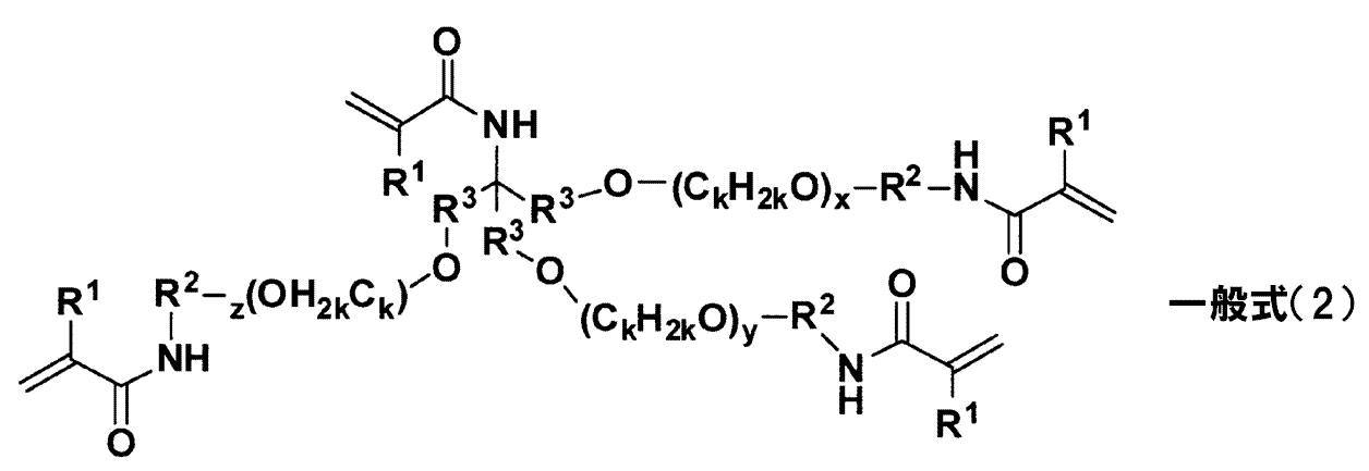
<10> 前記記録媒体が、原紙と無機顔料を含む塗工層とを有する塗工紙である前記<1>~前記<9>のいずれか1つに記載の画像記録方法である。
<11> 前記インク組成物が、更に、重合開始剤を含む前記<1>~前記<10>のいずれか1つに記載の画像記録方法である。
<12> 更に、前記インク組成物中の成分を凝集させる凝集成分を含有する処理液を記録媒体に付与する処理液付与工程を有する前記<1>~前記<11>のいずれか1つに記載の画像記録方法である。
<13> 前記処理液が、酸、多価金属塩、及びカチオン性ポリマーから選択される少なくとも一種を含む前記<12>に記載の画像記録方法である。
<14> 前記凝集成分が、酸である<12>に記載の画像記録方法。
<15> 前記処理液付与工程は、インク付与工程の前に設けられる前記<12>~前記<14>のいずれか1つに記載の画像記録方法である。
<11> 前記インク組成物が、更に、重合開始剤を含む前記<1>~前記<10>のいずれか1つに記載の画像記録方法である。
<12> 更に、前記インク組成物中の成分を凝集させる凝集成分を含有する処理液を記録媒体に付与する処理液付与工程を有する前記<1>~前記<11>のいずれか1つに記載の画像記録方法である。
<13> 前記処理液が、酸、多価金属塩、及びカチオン性ポリマーから選択される少なくとも一種を含む前記<12>に記載の画像記録方法である。
<14> 前記凝集成分が、酸である<12>に記載の画像記録方法。
<15> 前記処理液付与工程は、インク付与工程の前に設けられる前記<12>~前記<14>のいずれか1つに記載の画像記録方法である。
本発明によれば、排紙集積部に多数枚の記録媒体を集積した場合のスタッカーブロッキング及び光沢ムラの発生が防止される画像記録方法が提供される。
以下、本発明の画像記録方法について詳細に説明する。
本開示において「工程」との語は、独立した工程だけでなく、他の工程と明確に区別できない場合であっても本工程の所期の作用が達成されれば、本用語に含まれる。
本開示において「~」を用いて示された数値範囲は、「~」の前後に記載される数値をそれぞれ最小値及び最大値として含む範囲を示す。
本開示において、組成物中の各成分の量について言及する場合、組成物中に各成分に該当する物質が複数存在する場合には、特に断らない限り、組成物中に存在する当該複数の物質の合計量を意味する。
本開示において、「(メタ)アクリルアミド」は、アクリルアミド又はメタクリルアミドを意味し、「(メタ)アクリル酸」は、アクリル酸又はメタクリル酸を意味し、「(メタ)アクリレート」は、アクリレート又はメタクリレートを意味する。
本開示において「工程」との語は、独立した工程だけでなく、他の工程と明確に区別できない場合であっても本工程の所期の作用が達成されれば、本用語に含まれる。
本開示において「~」を用いて示された数値範囲は、「~」の前後に記載される数値をそれぞれ最小値及び最大値として含む範囲を示す。
本開示において、組成物中の各成分の量について言及する場合、組成物中に各成分に該当する物質が複数存在する場合には、特に断らない限り、組成物中に存在する当該複数の物質の合計量を意味する。
本開示において、「(メタ)アクリルアミド」は、アクリルアミド又はメタクリルアミドを意味し、「(メタ)アクリル酸」は、アクリル酸又はメタクリル酸を意味し、「(メタ)アクリレート」は、アクリレート又はメタクリレートを意味する。
本発明の画像記録方法は、着色剤、水、重合性化合物、及びガラス転移温度(Tg)が80℃以上150℃以下のポリマー粒子を含むインク組成物をインクジェット法により記録媒体に付与し、画像を記録するインク付与工程と、記録された画像を乾燥させる乾燥工程と、乾燥後の画像に活性エネルギー線を照射することで画像を硬化させる硬化工程と、硬化後の画像を、冷却前後での温度差が15℃以上となるよう冷却する冷却工程と、冷却後の記録媒体を複数枚積み重ねて集積する集積工程とを含む。また、本発明の画像記録方法は、必要に応じて、更に、他の工程を含んでいてもよい。
インクジェット法で画像記録する場合に重合性化合物を含む硬化系インクを用いると、インクを硬化するため、非硬化系のインクとは異なり、複数枚を積み重ねて集積した場合の記録媒体間におけるスタッカーブロッキングや光沢ムラは生じないものと思われていた。商業用途での画像記録においては、生産性の点から高速で多数枚(例えば1000枚以上)の記録媒体を積み重ねて回収した場合、および重量のある紙材(例えばコート紙や板紙などの塗工紙)に記録しこれらを積み重ねた場合等に、記録画像にかかる荷重が従来より増す傾向にある。本発明者らは、そのような場合には、硬化系のインクであってもスタッカーブロッキングや光沢ムラが発生することを見出し、鋭意検討した結果、特定のポリマー粒子を用い、画像の温度を変化(冷却)させることで、硬化系のインクにおいて、スタッカーブロッキングと光沢ムラの発生の防止を両立し得るに至った。
具体的には、本発明の画像記録方法においては、重合性化合物を含む硬化系インク組成物を用い、ポリマー粒子のTgを所定の範囲に調整し、かつ乾燥、硬化後の画像に対して所定の冷却を施す。これにより、集積時に記録画像に記録媒体や他の画像が接触して加重がかかったときの画像変形が小さくなり、記録画像の記録媒体や他の画像との接触面積が少なくなり、密着力が低く抑えられると推測される。つまり、ポリマー粒子のTgを画像のクッツキ(sticking)が抑制され、かつ画像が脆くなりにくい範囲とし、さらに溶媒含量や画像温度によっては樹脂成分に起因して画像変形(画像との接触面積の変化)しやすい状況を冷却により防ぐ点が重要と考えられる。結果、比較的高速にあるいは両面に画像形成されたときでも、画像部の強度を保つことができ、隣接する記録媒体との接触面積が大きくなって画像が剥がれやすい状態のまま記録媒体が積み重ねられるのを回避することができる。このように、本発明の方法では、多数枚が集積された記録媒体間におけるスタッカーブロッキング及び光沢ムラの発生が効果的に防止され、画像品質の高い記録物を提供することが可能になる。
具体的には、本発明の画像記録方法においては、重合性化合物を含む硬化系インク組成物を用い、ポリマー粒子のTgを所定の範囲に調整し、かつ乾燥、硬化後の画像に対して所定の冷却を施す。これにより、集積時に記録画像に記録媒体や他の画像が接触して加重がかかったときの画像変形が小さくなり、記録画像の記録媒体や他の画像との接触面積が少なくなり、密着力が低く抑えられると推測される。つまり、ポリマー粒子のTgを画像のクッツキ(sticking)が抑制され、かつ画像が脆くなりにくい範囲とし、さらに溶媒含量や画像温度によっては樹脂成分に起因して画像変形(画像との接触面積の変化)しやすい状況を冷却により防ぐ点が重要と考えられる。結果、比較的高速にあるいは両面に画像形成されたときでも、画像部の強度を保つことができ、隣接する記録媒体との接触面積が大きくなって画像が剥がれやすい状態のまま記録媒体が積み重ねられるのを回避することができる。このように、本発明の方法では、多数枚が集積された記録媒体間におけるスタッカーブロッキング及び光沢ムラの発生が効果的に防止され、画像品質の高い記録物を提供することが可能になる。
-インク付与工程-
本発明におけるインク付与工程は、着色剤、水、重合性化合物、及びガラス転移温度が80℃以上150℃以下のポリマー粒子を含むインク組成物をインクジェット法により記録媒体に付与し、画像を記録する工程である。
本発明におけるインク付与工程は、着色剤、水、重合性化合物、及びガラス転移温度が80℃以上150℃以下のポリマー粒子を含むインク組成物をインクジェット法により記録媒体に付与し、画像を記録する工程である。
インクジェット法による画像記録は、エネルギーを供与することにより、記録媒体上にインク組成物を液滴状にして吐出し、画像を形成する。なお、インクジェット法としては、例えば、特開2003-306623号公報の段落番号0093~0105に記載の方法が適用できる。
インクジェット法には、特に制限はなく、公知の方式、例えば、静電誘引力を利用してインクを吐出させる電荷制御方式、ピエゾ素子の振動圧力を利用するドロップオンデマンド方式(圧力パルス方式)、電気信号を音響ビームに変えインクに照射して放射圧を利用してインクを吐出させる音響インクジェット方式、及びインクを加熱して気泡を形成し、生じた圧力を利用するサーマルインクジェット方式等のいずれを用いてもよい。インクジェット法としては、特に、特開昭54-59936号公報に記載の方法で、熱エネルギーの作用を受けたインクが急激な体積変化を生じ、この状態変化による作用力によって、インクをノズルから吐出させるインクジェット法を有効に利用することができる。
尚、インクジェット法には、フォトインクと称する濃度の低いインクを小さい体積で多数射出する方式、実質的に同じ色相で濃度の異なる複数のインクを用いて画質を改良する方式、および無色透明のインクを用いる方式が含まれる。
尚、インクジェット法には、フォトインクと称する濃度の低いインクを小さい体積で多数射出する方式、実質的に同じ色相で濃度の異なる複数のインクを用いて画質を改良する方式、および無色透明のインクを用いる方式が含まれる。
また、インク付与工程では、例えば記録媒体の搬送速度を変えることにより画像記録することができる。搬送速度は、画像品質を損なわない範囲であれば特に制限はなく、好ましくは、100~3000mm/sであり、より好ましくは150~2700mm/sであり、さらに好ましくは250~2500mm/sである。搬送速度が上記範囲内であると、比較的高速に画像を記録する場合に生じやすいスタッカーブロッキング及び光沢ムラの発生防止効果がより奏される。
本発明においては、インク組成物の記録媒体への最大付与量は15ml/m2以下であることが好ましい。最大付与量が15ml/m2以下であることで、画像の記録媒体への密着性により優れる。更には、最大付与量としては、画像の記録媒体への密着性と濃度の観点から、8~15ml/m2がより好ましい。最大付与量は、吐出ノズルからの吐出方法を調節することにより制御することができる。
~記録媒体~
本発明における記録媒体としては、特に制限はないが、例えば、一般のオフセット印刷などに用いられる、いわゆる上質紙、塗工紙、アート紙などのセルロースを主体とする一般印刷用紙を用いることができる。セルロースを主体とする一般印刷用紙を用いる場合、水性インクを用いた一般のインクジェット法による画像記録においては比較的インクの吸収および乾燥が遅く、打滴後に色材移動が起こりやすく、画像品質が低下しやすいが、本発明の画像記録方法によると、色材移動を抑制して色濃度および色相に優れた高品位の画像の記録が可能である。
本発明における記録媒体としては、特に制限はないが、例えば、一般のオフセット印刷などに用いられる、いわゆる上質紙、塗工紙、アート紙などのセルロースを主体とする一般印刷用紙を用いることができる。セルロースを主体とする一般印刷用紙を用いる場合、水性インクを用いた一般のインクジェット法による画像記録においては比較的インクの吸収および乾燥が遅く、打滴後に色材移動が起こりやすく、画像品質が低下しやすいが、本発明の画像記録方法によると、色材移動を抑制して色濃度および色相に優れた高品位の画像の記録が可能である。
記録媒体としては、一般に市販されているものを使用してもよい。例えば、上質紙(A)(例:王子製紙(株)製の「OKプリンス上質」、日本製紙(株)製の「しおらい」、日本製紙(株)製の「ニューNPI上質」等)、微塗工紙(例:王子製紙(株)製の「OKエバーライトコート」及び日本製紙(株)製の「オーロラS」等)、軽量コート紙(A3)(例:王子製紙(株)製の「OKコートL」及び日本製紙(株)製の「オーロラL」等)、コート紙(A2、B2)(例:王子製紙(株)製の「OKトップコート+」、日本製紙(株)製の「オーロラコート」等)、アート紙(A1)(王子製紙(株)製の「OK金藤+」、三菱製紙(株)製の「特菱アート」等)、板紙(例えば、高級白板紙(例:日本大昭和板紙(株)製のアイベストW、ユニフィエイスW、F-1カード、ベストマット、リバース70、ニューアイポスト)、特殊白板紙(例:日本大昭和板紙(株)製のNEWウルトラH、ウルトラH、NEWリファイン、JETエースW)などの白板紙)、等が挙げられる。また、インクジェット記録用の各種写真専用紙を用いることも可能である。
記録媒体の中でも、一般のオフセット印刷などに用いられる、いわゆる塗工紙が好ましい。塗工紙は、セルロースを主体とした一般に表面処理されていない上質紙や中性紙等の原紙の表面にコート材を塗布して塗工層を設けたものである。塗工紙は、通常の水性インクをインクジェット法で吐出して画像記録する場合には、画像の光沢や擦過耐性などについて品質上の問題を生じやすい。一方、本発明の画像記録方法では、塗工紙を用いた場合であっても、多数枚の記録媒体を積み重ねたときの光沢ムラ及びクッツキ等に起因するスタッカーブロッキングの発生が抑制された画像を得ることができる。特に、光沢ムラ及び塗工層が破壊されて生じるスタッカーブロッキングの防止効果が顕著に現れる観点から、原紙と無機顔料を含む塗工層とを有する塗工紙を用いるのが好ましく、原紙とカオリン及び/又は重炭酸カルシウムを含む塗工層とを有する塗工紙を用いるのがより好ましい。具体的には、アート紙、コート紙、軽量コート紙、微塗工紙、又は板紙がより好ましい。
~インク組成物~
ここで、インク組成物に含まれる各成分について詳述する。
本発明におけるインク組成物は、着色剤、水、重合性化合物、及びガラス転移温度が80℃以上150℃以下のポリマー粒子を少なくとも含み、必要に応じて、更に、水溶性有機溶剤、界面活性剤、ワックス、および/またはその他添加剤などを含んでいてもよい。
ここで、インク組成物に含まれる各成分について詳述する。
本発明におけるインク組成物は、着色剤、水、重合性化合物、及びガラス転移温度が80℃以上150℃以下のポリマー粒子を少なくとも含み、必要に応じて、更に、水溶性有機溶剤、界面活性剤、ワックス、および/またはその他添加剤などを含んでいてもよい。
[着色剤]
本発明におけるインク組成物は、着色剤の少なくとも一種を含有する。着色剤としては、公知の染料、顔料等を特に制限なく用いることができる。中でも、インク着色性の観点から、水に不溶又は難溶の着色剤が好ましく、例えば、各種顔料、分散染料、油溶性染料、J会合体を形成する色素等を挙げることができる。着色剤としては、耐光性の観点から、顔料がより好ましい。
本発明におけるインク組成物は、着色剤の少なくとも一種を含有する。着色剤としては、公知の染料、顔料等を特に制限なく用いることができる。中でも、インク着色性の観点から、水に不溶又は難溶の着色剤が好ましく、例えば、各種顔料、分散染料、油溶性染料、J会合体を形成する色素等を挙げることができる。着色剤としては、耐光性の観点から、顔料がより好ましい。
顔料としては、特に制限はなく、目的に応じて適宜選択することができ、例えば、有機顔料、無機顔料のいずれであってもよい。有機顔料としては、例えば、アゾ顔料、多環式顔料、染料キレート、ニトロ顔料、ニトロソ顔料、アニリンブラック、などが挙げられる。これらの中でも、アゾ顔料、多環式顔料などがより好ましい。アゾ顔料としては、例えば、アゾレーキ、不溶性アゾ顔料、縮合アゾ顔料、キレートアゾ顔料、などが挙げられる。多環式顔料としては、例えば、フタロシアニン顔料、ぺリレン顔料、ぺリノン顔料、アントラキノン顔料、キナクリドン顔料、ジオキサジン顔料、インジゴ顔料、チオインジゴ顔料、イソインドリノン顔料、キノフタロン顔料、などが挙げられる。染料キレートとしては、例えば、塩基性染料型キレート、酸性染料型キレート、などが挙げられる。
無機顔料としては、例えば、酸化チタン、酸化鉄、炭酸カルシウム、硫酸バリウム、水酸化アルミニウム、バリウムイエロー、カドミウムレッド、クロムイエロー、カーボンブラック、などが挙げられる。カーボンブラックとしては、例えば、コンタクト法、ファーネス法、サーマル法などの公知の方法によって製造されたものが挙げられる。
無機顔料としては、例えば、酸化チタン、酸化鉄、炭酸カルシウム、硫酸バリウム、水酸化アルミニウム、バリウムイエロー、カドミウムレッド、クロムイエロー、カーボンブラック、などが挙げられる。カーボンブラックとしては、例えば、コンタクト法、ファーネス法、サーマル法などの公知の方法によって製造されたものが挙げられる。
(分散剤)
本発明におけるインク組成物は、分散剤の少なくとも1種を含有してもよい。例えば顔料の分散剤として、ポリマー分散剤又は低分子の界面活性剤型分散剤を用いることができる。また、ポリマー分散剤は、水溶性の分散剤又は非水溶性の分散剤のいずれでもよい。
本発明におけるインク組成物は、分散剤の少なくとも1種を含有してもよい。例えば顔料の分散剤として、ポリマー分散剤又は低分子の界面活性剤型分散剤を用いることができる。また、ポリマー分散剤は、水溶性の分散剤又は非水溶性の分散剤のいずれでもよい。
低分子の界面活性剤型分散剤は、インクを低粘度に保ちつつ、顔料を水溶媒に安定に分散させることができる。低分子の界面活性剤型分散剤は、分子量2,000以下の低分子分散剤である。また、低分子の界面活性剤型分散剤の分子量は、100~2,000が好ましく、200~2,000がより好ましい。
低分子の界面活性剤型分散剤は、親水性基と疎水性基とを含む構造を有している。また、親水性基と疎水性基とは、それぞれ独立に低分子の界面活性剤型分散剤の1分子に1以上含まれていればよく、また、複数種類の親水性基および/または疎水性基を有していてもよい。また低分子の界面活性剤型分散剤は、親水性基と疎水性基とを連結するための連結基も適宜有することができる。
前記親水性基としては、アニオン性、カチオン性、ノニオン性、あるいはこれらを組み合わせたベタイン型の親水性基等が挙げられる。アニオン性の親水性基は、マイナスの電荷を有するものであればいずれでもよいが、リン酸基、ホスホン酸基、ホスフィン酸基、硫酸基、スルホン酸基、スルフィン酸基又はカルボン酸基であることが好ましく、リン酸基、カルボン酸基であることがより好ましく、カルボン酸基であることがさらに好ましい。カチオン性の親水性基は、プラスの荷電を有するものであればいずれでもよいが、有機のカチオン性置換基であることが好ましく、窒素又はリンのカチオン性基であることがより好ましい。また、ピリジニウムカチオン又はアンモニウムカチオンであることがさらに好ましい。ノニオン性の親水性基としては、ポリエチレンオキシドやポリグリセリン、糖ユニットの一部等が挙げられる。
前記親水性基は、アニオン性の親水性基であることが好ましい。アニオン性の親水性基は、リン酸基、ホスホン酸基、ホスフィン酸基、硫酸基、スルホン酸基、スルフィン酸基、又はカルボン酸基であることが好ましく、リン酸基、カルボン酸基であることがより好ましく、カルボン酸基であることがさらに好ましい。
また、低分子の界面活性剤型分散剤がアニオン性の親水性基を有する場合、酸性の処理液と接触させて凝集反応を促進させる観点から、低分子の界面活性剤型分散剤のpKaは3以上であることが好ましい。低分子の界面活性剤型分散剤のpKaは、テトラヒドロフラン-水(3:2=V/V)溶液に低分子の界面活性剤型分散剤1mmol/Lを溶解した液を酸あるいはアルカリ水溶液で滴定し、滴定曲線より実験的に求めた値のことである。低分子の界面活性剤型分散剤のpKaが3以上であると、理論上pH3程度の液と接したときにアニオン性基の50%以上が非解離状態になる。したがって、酸性の処理液と接触させた際に低分子の界面活性剤型分散剤の水溶性が著しく低下し、凝集反応が起こる。すなわち、凝集反応性が向上する。かかる観点からも、低分子の界面活性剤型分散剤は、アニオン性基としてカルボン酸基を有する場合が好ましい。
前記疎水性基としては、炭化水素系、フッ化炭素系、またはシリコーン系等の構造を有する基が挙げられ、特に炭化水素系の疎水性基であることが好ましい。また、疎水性基の構造は、直鎖状構造又は分岐状構造のいずれであってもよい。また、疎水性基の構造は、1本鎖状構造又は2本鎖以上の鎖状構造でもよく、2本鎖状以上の構造である場合は、複数種類の疎水性基を有していてもよい。
また、疎水性基は、炭素数2~24の炭化水素基が好ましく、炭素数4~24の炭化水素基がより好ましく、炭素数6~20の炭化水素基がさらに好ましい。
また、疎水性基は、炭素数2~24の炭化水素基が好ましく、炭素数4~24の炭化水素基がより好ましく、炭素数6~20の炭化水素基がさらに好ましい。
前記ポリマー分散剤のうち、水溶性分散剤としては、親水性高分子化合物が挙げられる。例えば、親水性高分子化合物としては、、アラビアガム、トラガンガム、グアーガム、カラヤガム、ローカストビーンガム、アラビノガラクトン、ペクチン、クインスシードデンプン等の植物性高分子、アルギン酸、カラギーナン、寒天等の海藻系高分子、ゼラチン、カゼイン、アルブミン、コラーゲン等の動物系高分子、キサンテンガム、デキストラン等の微生物系高分子等の天然の親水性高分子化合物が挙げられる。
また、前記親水性高分子化合物の例としては、メチルセルロース、エチルセルロース、ヒドロキシエチルセルロース、ヒドロキシプロピルセルロース、カルボキシメチルセルロース等の繊維素系高分子、デンプングリコール酸ナトリウム、デンプンリン酸エステルナトリウム等のデンプン系高分子、アルギン酸ナトリウム、アルギン酸プロピレングリコールエステル等の海藻系高分子等の天然物を原料に修飾した親水性高分子化合物が挙げられる。
更に、前記親水性高分子化合物の例としては、ポリビニルアルコール、ポリビニルピロリドン、ポリビニルメチルエーテル等のビニル系高分子、非架橋ポリアクリルアミド、ポリアクリル酸又はそのアルカリ金属塩、水溶性スチレンアクリル樹脂等のアクリル系樹脂、水溶性スチレンマレイン酸樹脂、水溶性ビニルナフタレンアクリル樹脂、水溶性ビニルナフタレンマレイン酸樹脂、ポリビニルピロリドン、ポリビニルアルコール、β-ナフタレンスルホン酸ホルマリン縮合物のアルカリ金属塩、四級アンモニウムやアミノ基等のカチオン性官能基の塩を側鎖に有する高分子化合物、セラック等の天然高分子化合物等の合成系の親水性高分子化合物が挙げられる。
更に、前記親水性高分子化合物の例としては、ポリビニルアルコール、ポリビニルピロリドン、ポリビニルメチルエーテル等のビニル系高分子、非架橋ポリアクリルアミド、ポリアクリル酸又はそのアルカリ金属塩、水溶性スチレンアクリル樹脂等のアクリル系樹脂、水溶性スチレンマレイン酸樹脂、水溶性ビニルナフタレンアクリル樹脂、水溶性ビニルナフタレンマレイン酸樹脂、ポリビニルピロリドン、ポリビニルアルコール、β-ナフタレンスルホン酸ホルマリン縮合物のアルカリ金属塩、四級アンモニウムやアミノ基等のカチオン性官能基の塩を側鎖に有する高分子化合物、セラック等の天然高分子化合物等の合成系の親水性高分子化合物が挙げられる。
これらの中でも、アクリル酸、メタクリル酸、またはスチレンアクリル酸の、ホモポリマーおよび他の親水基を有するモノマーとの共重合体などのように、カルボキシル基が導入された水溶性分散剤が親水性高分子化合物として好ましい。
前記ポリマー分散剤のうち、非水溶性分散剤としては、疎水性部と親水性部の両方を有するポリマーを用いることができる。例えば、スチレン-(メタ)アクリル酸共重合体、スチレン-(メタ)アクリル酸-(メタ)アクリル酸エステル共重合体、(メタ)アクリル酸エステル-(メタ)アクリル酸共重合体、ポリエチレングリコール(メタ)アクリレート-(メタ)アクリル酸共重合体、酢酸ビニル-マレイン酸共重合体、スチレン-マレイン酸共重合体等が挙げられる。
ポリマー分散剤の重量平均分子量は、3,000~100,000が好ましく、より好ましくは5,000~50,000であり、更に好ましくは5,000~40,000であり、特に好ましくは10,000~40,000である。
ポリマー分散剤は、自己分散性、及び処理液が接触したときの凝集速度の観点から、カルボキシル基を有するポリマーを含むことが好ましく、カルボキシル基を有し、酸価が100mgKOH/g以下のポリマーであることが好ましく、酸価は25~100mgKOH/gのポリマーがより好ましい。特に、本発明におけるインク組成物を、インク組成物中の成分を凝集させる処理液と共に用いる場合には、カルボキシル基を有し、かつ酸価が25~100mgKOH/gのポリマー分散剤が有効である。処理液については、後述する。
前記顔料(p)と前記分散剤(s)との混合質量比(p:s)としては、1:0.06~1:3の範囲が好ましく、1:0.125~1:2の範囲がより好ましく、更に好ましくは1:0.125~1:1.5の範囲である。
本発明においては、顔料に代えて染料を用いてもよい。染料を用いる場合には、染料を水不溶性の担体に保持したものを用いることができる。染料を保持した担体(水不溶性着色粒子)は、分散剤を用いて水系分散物として用いることができる。分散剤としては、上述の分散剤を好適に用いることができる。
本発明においては、画像の耐光性や品質などの観点から、インク組成物は、顔料と分散剤と含むことが好ましく、有機顔料とポリマー分散剤とを含み、顔料表面の少なくとも一部がポリマー分散剤で被覆された水分散性顔料として含むことがより好ましい。更には、インク組成物は、有機顔料とカルボキシル基を含むポリマー分散剤とを含み、顔料表面の少なくとも一部がカルボキシル基を有するポリマー分散剤で被覆された水分散性顔料を含むことが特に好ましく、凝集性の観点から、顔料はカルボキシル基を含むポリマー分散剤に被覆されて水不溶性であることが好ましい。
分散状態での顔料の平均粒子径としては、10~200nmが好ましく、10~150nmがより好ましく、10~100nmがさらに好ましい。平均粒子径が200nm以下であると、色再現性が良好になり、インクジェット法で打滴する際の打滴特性が良好になる。平均粒子径が10nm以上であると、耐光性が良好になる。また、色材の粒径分布に関しては、特に制限はなく、広い粒径分布又は単分散性の粒径分布のいずれであってもよい。また、単分散性の粒径分布を持つ色材を2種以上混合して使用してもよい。ここで、分散状態での顔料の平均粒子径は、インク化した状態での平均粒子径を示すが、インク化する前段階のいわゆる濃縮インク分散物についても同様である。
なお、分散状態での顔料の平均粒子径及び粒径分布は、ナノトラック粒度分布測定装置UPA-EX150(日機装(株)製)を用いて、動的光散乱法により体積平均粒径を測定することにより求められるものである。
なお、分散状態での顔料の平均粒子径及び粒径分布は、ナノトラック粒度分布測定装置UPA-EX150(日機装(株)製)を用いて、動的光散乱法により体積平均粒径を測定することにより求められるものである。
着色剤は、一種単独で使用してもよく、また上記した各群内もしくは各群間より複数種選択してこれらを組み合わせて使用してもよい。
着色剤のインク組成物中における含有量は、着色性、保存安定性等の観点から、インク組成物の全固形分質量に対して、0.1~20質量%が好ましく、0.2~15質量%がより好ましく、0.5~10質量%が特に好ましい。
着色剤のインク組成物中における含有量は、着色性、保存安定性等の観点から、インク組成物の全固形分質量に対して、0.1~20質量%が好ましく、0.2~15質量%がより好ましく、0.5~10質量%が特に好ましい。
[ポリマー粒子]
本発明におけるインク組成物は、ガラス転移温度が80℃以上150℃以下のポリマー粒子の少なくとも一種を含有する。ポリマー粒子は、既述のポリマー分散剤(顔料等の少なくとも一部を覆うポリマー分散剤)とは別にインク中に分散含有される粒子である。
本発明におけるインク組成物は、ガラス転移温度が80℃以上150℃以下のポリマー粒子の少なくとも一種を含有する。ポリマー粒子は、既述のポリマー分散剤(顔料等の少なくとも一部を覆うポリマー分散剤)とは別にインク中に分散含有される粒子である。
ポリマー粒子は、後述する処理液又はこれを乾燥させた領域と接触した際に、インク組成物中において分散不安定化して凝集し、インク組成物を増粘することによりインク組成物を固定化する機能を有し、インク組成物の記録媒体への密着性及び画像の耐傷性をより向上させることができる。
ポリマー粒子は、例えば、粒子状にしたポリマーを水性媒体に分散させたラテックスとして用いることができる。ポリマーとしては、アクリル系樹脂、酢酸ビニル系樹脂、スチレン-ブタジエン系樹脂、塩化ビニル系樹脂、アクリル-スチレン系樹脂、ブタジエン系樹脂、スチレン系樹脂、架橋アクリル樹脂、架橋スチレン系樹脂、ベンゾグアナミン樹脂、フェノール樹脂、シリコーン樹脂、エポキシ樹脂、ウレタン系樹脂、パラフィン系樹脂、フッ素系樹脂等を用いることができる。中でも、アクリル系樹脂、アクリル-スチレン系樹脂、スチレン系樹脂、架橋アクリル樹脂、架橋スチレン系樹脂が好ましい例として挙げられる。
水性媒体は、水を含み、必要に応じて親水性有機溶媒を含んでいてもよい。本発明においては、水と水に対して0.2質量%以下の親水性有機溶媒とを含む水性媒体が好ましく、水のみからなる媒体がより好ましい。
水性媒体は、水を含み、必要に応じて親水性有機溶媒を含んでいてもよい。本発明においては、水と水に対して0.2質量%以下の親水性有機溶媒とを含む水性媒体が好ましく、水のみからなる媒体がより好ましい。
本発明においては、ガラス転移温度(Tg)が80℃以上150℃以下であるポリマー粒子を含有することで、集積回収したときのスタッカーブロッキングの発生が抑制され、画像の光沢ムラも抑制される。換言すると、Tgは、80℃未満であるとクッツキが生じやすく、光沢ムラ及びスタッカーブロッキング発生の一因となる。また、Tgが150℃を超える範囲では、画像が脆化し、クッツキが生じた画像部を剥がす際に画像が破壊され、スタッカーブロッキング発生の一因となる。
本発明におけるポリマー粒子のTgは、スタッカーブロッキング及び光沢ムラの発生をより効果的に防ぐ観点から、90℃以上140℃以下の範囲がより好ましく、100℃以上130℃以下の範囲が更に好ましい。
ポリマー粒子のガラス転移温度(Tg)は、通常用いられる方法によって適宜制御することができる。例えば、ポリマー粒子を構成するモノマー(重合性化合物)の種類やその構成比率、ポリマー粒子を構成するポリマーの分子量等を適宜選択することで、ポリマー粒子のガラス転移温度(Tg)を所望の範囲に制御することができる。
本発明において、ポリマー粒子のガラス転移温度(Tg)は、実測によって得られる測定Tgを適用する。具体的には、測定Tgとしては、エスアイアイ・ナノテクノロジー(株)製の示差走査熱量計(DSC)EXSTAR6220を用いて通常の測定条件で測定された値を意味する。但し、ポリマーの分解等により測定が困難な場合には、下記の計算式で算出される計算Tgを適用する。計算Tgは下記式(1)で計算されるものである。
1/Tg=Σ(Xi/Tgi) ・・・(1)
ここで、計算対象となるポリマーはi=1からnまでのn種のモノマー成分が共重合しているとする。Xiはi番目のモノマーの重量分率(ΣXi=1)、Tgiはi番目のモノマーの単独重合体のガラス転移温度(絶対温度)である。但し、Σはi=1からnまでの和をとる。尚、各モノマーの単独重合体ガラス転移温度の値(Tgi)は、Polymer Handbook(3rd Edition)(J.Brandrup,E.H.Immergut著(Wiley-Interscience、1989))の値を採用したものである。
1/Tg=Σ(Xi/Tgi) ・・・(1)
ここで、計算対象となるポリマーはi=1からnまでのn種のモノマー成分が共重合しているとする。Xiはi番目のモノマーの重量分率(ΣXi=1)、Tgiはi番目のモノマーの単独重合体のガラス転移温度(絶対温度)である。但し、Σはi=1からnまでの和をとる。尚、各モノマーの単独重合体ガラス転移温度の値(Tgi)は、Polymer Handbook(3rd Edition)(J.Brandrup,E.H.Immergut著(Wiley-Interscience、1989))の値を採用したものである。
ポリマー粒子としては、転相乳化法により得られたポリマー粒子であること、すなわち有機溶媒中で合成され、アニオン性基の一部又は全部を中和して、水を連続相とする分散体として調製された粒子であることが好ましく、下記の自己分散性ポリマーの粒子(自己分散性ポリマー粒子)がより好ましい。
ここで、自己分散性ポリマーとは、界面活性剤の不存在下、転相乳化法により分散状態としたとき、ポリマー自身が有する官能基(特に酸性基又はその塩)によって、水性媒体中で分散状態となり得る水不溶性ポリマーをいう。
ここで、分散状態とは、水性媒体中に水不溶性ポリマーが液体状態で分散された乳化状態(エマルション)、及び、水性媒体中に水不溶性ポリマーが固体状態で分散された分散状態(サスペンジョン)の両方の状態を含むものである。
また、「水不溶性」とは、水100質量部(25℃)に対する溶解量が5.0質量部以下であることを指す。
ここで、自己分散性ポリマーとは、界面活性剤の不存在下、転相乳化法により分散状態としたとき、ポリマー自身が有する官能基(特に酸性基又はその塩)によって、水性媒体中で分散状態となり得る水不溶性ポリマーをいう。
ここで、分散状態とは、水性媒体中に水不溶性ポリマーが液体状態で分散された乳化状態(エマルション)、及び、水性媒体中に水不溶性ポリマーが固体状態で分散された分散状態(サスペンジョン)の両方の状態を含むものである。
また、「水不溶性」とは、水100質量部(25℃)に対する溶解量が5.0質量部以下であることを指す。
前記転相乳化法としては、例えば、ポリマーを溶媒(例えば、水溶性有機溶剤等)中に溶解又は分散させた後、界面活性剤を添加せずにそのまま水中に投入し、ポリマーが有する塩生成基(例えば、酸性基)を中和した状態で、攪拌、混合し、前記溶媒を除去した後、乳化又は分散状態となった水性分散物を得る方法が挙げられる。
前記自己分散性ポリマー粒子としては、例えば、特開2010-64480号公報の段落0090~0121、および特開2011-068085号公報の段落0130~0167に記載されている自己分散性ポリマー粒子の中から、Tgが80℃以上150℃以下にあるものを選択して用いることができる。
前記ポリマー粒子を形成するポリマーは、芳香環構造(芳香族基)を有する構造単位及び脂環構造(脂環族基)を有する構造単位の少なくとも一方を有することが好ましい。ここで、脂環族基は、環状脂肪族基と同義である。これにより、形成された画像の強度(例えば耐傷性や耐ブロッキング性)がより向上し、集積されて荷重がかかったときの画像の変形、すなわち画像と該画像に接触する記録媒体や他の画像との間の接触面積の増加が小さく抑えられるので、スタッカーブロッキングの発生抑制に効果的である。
芳香族基を有する構造単位としては、フェニル基を有する構造単位、ベンジル基を有する構造単位、フェノキシ基を有する構造単位、フェネチル基を有する構造単位等が挙げられる。中でも、ベンジル基を有する構造単位、フェノキシ基を有する構造単位(好ましくはフェノキシエチル基を有する構造単位)が好ましい。
芳香族基を有する構造単位は、芳香族基を有するモノマー(以下、「芳香族基含有モノマー」ともいう。)に由来する構造単位であることが好ましい。芳香族基含有モノマーは、芳香族炭化水素に由来する芳香族基とエチレン性不飽和結合とを有するモノマーであることが好ましい。芳香族基含有モノマーは、1種単独でも、2種以上を組み合わせて用いてもよい。芳香族基含有モノマーの例としては、フェノキシエチル(メタ)アクリレート、ベンジル(メタ)アクリレート、フェニル(メタ)アクリレート、スチレン系モノマー等が挙げられる。中でも、ポリマー鎖の親水性と疎水性のバランスとインク定着性の観点から、芳香族基含有モノマーとしては、芳香族基含有(メタ)アクリレートモノマーが好ましく、フェノキシエチル(メタ)アクリレート、ベンジル(メタ)アクリレート、フェニル(メタ)アクリレートがより好ましく、フェノキシエチル(メタ)アクリレート、ベンジル(メタ)アクリレートが更に好ましい。
なお、「(メタ)アクリレート」は、アクリレート又はメタクリレートを意味する。
なお、「(メタ)アクリレート」は、アクリレート又はメタクリレートを意味する。
脂環族基を有する構造単位は、脂環族基を有するモノマー(以下、「脂環族基含有モノマー」ともいう)に由来する構造単位であることが好ましい。脂環族基含有モノマーは、脂環族基とエチレン性不飽和結合とを有するモノマーであることが好ましく、脂環族基を有する(メタ)アクリレート(以下、「脂環式(メタ)アクリレート」ともいう。)がより好ましい。
脂環式(メタ)アクリレートとは、(メタ)アクリル酸に由来する構造部位と、アルコールに由来する構造部位とを含み、アルコールに由来する構造部位に、無置換又は置換された脂環式炭化水素基を少なくとも1つ含む構造を有しているものである。尚、脂環式炭化水素基は、アルコールに由来する構造部位そのものであっても、連結基を介してアルコールに由来する構造部位に結合していてもよい。
脂環式(メタ)アクリレートとは、(メタ)アクリル酸に由来する構造部位と、アルコールに由来する構造部位とを含み、アルコールに由来する構造部位に、無置換又は置換された脂環式炭化水素基を少なくとも1つ含む構造を有しているものである。尚、脂環式炭化水素基は、アルコールに由来する構造部位そのものであっても、連結基を介してアルコールに由来する構造部位に結合していてもよい。
脂環式炭化水素基としては、環状の非芳香族炭化水素基を含むものであれば特に限定はなく、単環式炭化水素基、2環式炭化水素基、3環式以上の多環式炭化水素基が挙げられる。脂環式炭化水素基の例としては、シクロペンチル基、シクロヘキシル基などのシクロアルキル基、ならびにシクロアルケニル基、ビシクロヘキシル基、ノルボルニル基、イソボルニル基、ジシクロペンタニル基、ジシクロペンテニル基、アダマンチル基、デカヒドロナフタレニル基、ペルヒドロフルオレニル基、トリシクロ[5.2.1.02,6]デカニル基、及びビシクロ[4.3.0]ノナン等を挙げることができる。
脂環式炭化水素基は、更に置換基を有してもよい。該置換基としては、例えば、アルキル基、アルケニル基、アリール基、アラルキル基、アルコキシ基、水酸基、1級アミノ基、2級アミノ基、3級アミノ基、アルキル又はアリールカルボニル基、及びシアノ基等が挙げられる。また、脂環式炭化水素基は、さらに縮合環を形成していてもよい。本発明における脂環式炭化水素基としては、粘度や溶解性の観点から、脂環式炭化水素基部分の炭素数が5~20であることが好ましい。
脂環式炭化水素基は、更に置換基を有してもよい。該置換基としては、例えば、アルキル基、アルケニル基、アリール基、アラルキル基、アルコキシ基、水酸基、1級アミノ基、2級アミノ基、3級アミノ基、アルキル又はアリールカルボニル基、及びシアノ基等が挙げられる。また、脂環式炭化水素基は、さらに縮合環を形成していてもよい。本発明における脂環式炭化水素基としては、粘度や溶解性の観点から、脂環式炭化水素基部分の炭素数が5~20であることが好ましい。
脂環式(メタ)アクリレートの具体例を以下に示すが、本発明はこれらに限定されるものではない。単環式(メタ)アクリレートとしては、シクロプロピル(メタ)アクリレート、シクロブチル(メタ)アクリレート、シクロペンチル(メタ)アクリレート、シクロヘキシル(メタ)アクリレート、シクロヘプチル(メタ)アクリレート、シクロオクチル(メタ)アクリレート、シクロノニル(メタ)アクリレート、シクロデシル(メタ)アクリレート等のシクロアルキル基の炭素数が3~10のシクロアルキル(メタ)アクリレート等が挙げられる。2環式(メタ)アクリレートとしては、イソボルニル(メタ)アクリレート、ノルボルニル(メタ)アクリレート等が挙げられる。3環式(メタ)アクリレートとしては、アダマンチル(メタ)アクリレート、ジシクロペンタニル(メタ)アクリレート、ジシクロペンテニルオキシエチル(メタ)アクリレート等が挙げられる。
これらは、それぞれ単独で又は2種以上を混合して用いることができる。
これらは、それぞれ単独で又は2種以上を混合して用いることができる。
これらのうち、自己分散性ポリマー粒子の分散安定性と、定着性、スタッカーブロッキング耐性の観点から、脂環式(メタ)アクリレートとしては、2環式(メタ)アクリレートおよび3環式以上の多環式(メタ)アクリレートからなる群から選択される少なくとも1種であることが好ましく、イソボルニル(メタ)アクリレート、アダマンチル(メタ)アクリレート、及びジシクロペンタニル(メタ)アクリレートから選ばれる化合物がより好ましい。
中でも、ポリマー粒子としては、芳香族基を有する構造単位又は脂環族基を有する構造単位を有する共重合体の粒子が好ましく、更には、芳香族基含有(メタ)アクリレートモノマー由来の構造単位又は脂環式(メタ)アクリレート由来の構造単位を含む共重合体の粒子が好ましい。このとき、芳香族基を有する構造単位及び脂環族基を有する構造単位のポリマー粒子中における合計の比率は、5質量%~85質量%が好ましく、10質量%~75質量%がより好ましい。この比率が上記した範囲内にあると、ポリマー粒子のTgを80℃以上150℃以下の範囲に調整しやすく、ポリマー粒子の自己乳化又は分散状態の安定性も向上する。
また、ノズルからのインク組成物の除去性(メンテナンス性)や除去後の再吐出性も考慮すると、芳香族基を有する構造単位を含むポリマー粒子がより好ましい。
ポリマー粒子は、インク組成物中での分散性(自己分散性ポリマー粒子である場合には自己分散性)の観点から、親水性の構造単位を含むことが好ましい。
親水性の構造単位は、親水性基を有するモノマー(以下、「親水性基含有モノマー」ともいう)に由来する構造単位であることが好ましい。この場合、親水性の構造単位は、1種の親水性基含有モノマーに由来するものであっても、2種以上の親水性基含有モノマーに由来するものであってもよい。
親水性基としては、特に制限はなく、解離性基であってもノニオン性親水性基であってもよい。親水性基は、ポリマー粒子の自己分散促進の観点、および形成された乳化又は分散状態の安定性の観点から、解離性基であることが好ましく、アニオン性の解離性基であることがより好ましい。解離性基としては、カルボキシル基、リン酸基、スルホン酸基などが挙げられ、中でも、インク組成物とした場合の定着性の観点から、カルボキシル基が好ましい。
親水性の構造単位は、親水性基を有するモノマー(以下、「親水性基含有モノマー」ともいう)に由来する構造単位であることが好ましい。この場合、親水性の構造単位は、1種の親水性基含有モノマーに由来するものであっても、2種以上の親水性基含有モノマーに由来するものであってもよい。
親水性基としては、特に制限はなく、解離性基であってもノニオン性親水性基であってもよい。親水性基は、ポリマー粒子の自己分散促進の観点、および形成された乳化又は分散状態の安定性の観点から、解離性基であることが好ましく、アニオン性の解離性基であることがより好ましい。解離性基としては、カルボキシル基、リン酸基、スルホン酸基などが挙げられ、中でも、インク組成物とした場合の定着性の観点から、カルボキシル基が好ましい。
親水性基含有モノマーは、ポリマー粒子の自己分散性と凝集性の観点から、解離性基含有モノマーであることが好ましく、解離性基とエチレン性不飽和結合とを有する解離性基含有モノマーであることが好ましい。解離性基含有モノマーとしては、例えば、不飽和カルボン酸モノマー、不飽和スルホン酸モノマー、不飽和リン酸モノマー等が挙げられる。
不飽和カルボン酸モノマーとして、具体的には、(メタ)アクリル酸、クロトン酸、イタコン酸、マレイン酸、フマル酸、シトラコン酸、2-メタクリロイルオキシメチルコハク酸等が挙げられる。
不飽和スルホン酸モノマーとして、具体的には、スチレンスルホン酸、2-アクリルアミド-2-メチルプロパンスルホン酸、3-スルホプロピル(メタ)アクリレート、ビス-(3-スルホプロピル)-イタコン酸エステル等が挙げられる。
不飽和リン酸モノマーとして具体的には、ビニルホスホン酸、ビニルホスフェート、ビス(メタクリロキシエチル)ホスフェート、ジフェニル-2-アクリロイロキシエチルホスフェート、ジフェニル-2-メタクリロイロキシエチルホスフェート、ジブチル-2-アクリロイロキシエチルホスフェート等が挙げられる。
解離性基含有モノマーの中では、分散安定性、吐出安定性の観点から、不飽和カルボン酸モノマーが好ましく、(メタ)アクリル酸がより好ましい。
不飽和スルホン酸モノマーとして、具体的には、スチレンスルホン酸、2-アクリルアミド-2-メチルプロパンスルホン酸、3-スルホプロピル(メタ)アクリレート、ビス-(3-スルホプロピル)-イタコン酸エステル等が挙げられる。
不飽和リン酸モノマーとして具体的には、ビニルホスホン酸、ビニルホスフェート、ビス(メタクリロキシエチル)ホスフェート、ジフェニル-2-アクリロイロキシエチルホスフェート、ジフェニル-2-メタクリロイロキシエチルホスフェート、ジブチル-2-アクリロイロキシエチルホスフェート等が挙げられる。
解離性基含有モノマーの中では、分散安定性、吐出安定性の観点から、不飽和カルボン酸モノマーが好ましく、(メタ)アクリル酸がより好ましい。
親水性の構造単位のポリマー粒子中における含有比率は、特に制限はないが、分散安定性の観点から、ポリマー粒子の全量に対し、2質量%~30質量%が好ましく、5質量%~20質量%がより好ましく、5質量%~15質量%が特に好ましい。
ポリマー粒子は、ポリマー骨格の柔軟性やガラス転移温度(Tg)制御の容易さの観点から、アルキル基を有する構造単位を含むことが好ましい。アルキル基を有する構造単位におけるアルキル基の炭素数は、1~4が好ましい。アルキル基を有する構造単位は、アルキル基を有するモノマー(以下、「アルキル基含有モノマー」ともいう)に由来する構造単位であることが好ましい。
アルキル基含有モノマーとしては、例えば、メチル(メタ)アクリレート、エチル(メタ)アクリレート、イソプロピル(メタ)アクリレート、n-プロピル(メタ)アクリレート、n-ブチル(メタ)アクリレート、イソブチル(メタ)アクリレート、t-ブチル(メタ)アクリレート、ヘキシル(メタ)アクリレート、エチルヘキシル(メタ)アクリレート等のアルキル(メタ)アクリレート;ヒドロキシメチル(メタ)アクリレート、2-ヒドロキシエチル(メタ)アクリレート、2-ヒドロキシプロピル(メタ)アクリレート、4-ヒドロキシブチル(メタ)アクリレート、ヒドロキシペンチル(メタ)アクリレート、ヒドロキシヘキシル(メタ)アクリレート等の水酸基を有するエチレン性不飽和モノマー;ジメチルアミノエチル(メタ)アクリレート等のジアルキルアミノアルキル(メタ)アクリレート;N-ヒドロキシメチル(メタ)アクリルアミド、Nーヒドロキシエチル(メタ)アクリルアミド、N-ヒドロキシブチル(メタ)アクリルアミド等のN-ヒドロキシアルキル(メタ)アクリルアミド;N-メトキシメチル(メタ)アクリルアミド、N-エトキシメチル(メタ)アクリルアミド、N-(n-,イソ)ブトキシメチル(メタ)アクリルアミド、N-メトキシエチル(メタ)アクリルアミド、N-エトキシエチル(メタ)アクリルアミド、N-(n-、イソ)ブトキシエチル(メタ)アクリルアミド等のN-アルコキシアルキル(メタ)アクリルアミド等の(メタ)アクリルアミド等が挙げられる。
中でも、アルキル(メタ)アクリレートが好ましく、アルキル基の炭素数が1~4であるアルキル(メタ)アクリレートがより好ましく、メチル(メタ)アクリレート又はエチル(メタ)アクリレートが更に好ましく、メチル(メタ)アクリレートが特に好ましい。
中でも、アルキル(メタ)アクリレートが好ましく、アルキル基の炭素数が1~4であるアルキル(メタ)アクリレートがより好ましく、メチル(メタ)アクリレート又はエチル(メタ)アクリレートが更に好ましく、メチル(メタ)アクリレートが特に好ましい。
アルキル基を有する構造単位のポリマー粒子中における含有比率は、特に制限はないが、分散安定性の観点から、ポリマー粒子の全量に対し、5質量%~90質量%が好ましく、30質量%~80質量%がより好ましい。
前記ポリマー粒子は、必要に応じ、上述した構造単位以外の構造単位を含んでいてもよい。
本発明において、ポリマー粒子を形成するポリマーの共重合比率の好ましい形態は、ガラス転移温度を80℃以上150℃以下に調整し易く、かつ分散安定性を良好に維持する観点からみて、以下の形態である。
すなわち、好ましいポリマー粒子の形態は、芳香族基(好ましくは、ベンジル基、フェノキシ基)を有する構造単位を共重合比率として5質量%~60質量%(特に好ましくは、10質量%~55質量%)と、親水性の構造単位を共重合比率として2質量%~30質量(より好ましくは5質量%~20質量%、特に好ましくは5質量%~15質量%)と、アルキル基を有する構造単位を共重合比率として5質量%~90質量%(より好ましくは30質量%~80質量%)とを含む形態である。
特に好ましいポリマー粒子の形態は、ベンジル(メタ)アクリレートに由来する構造単位又はフェノキシエチル(メタ)アクリレートに由来する構造単位の少なくとも一方を共重合比率として5質量%~60質量%(特に好ましくは10質量%~55質量%)と、(メタ)アクリル酸に由来する構造単位を共重合比率として2質量%~30質量(より好ましくは5質量%~20質量%、特に好ましくは5質量%~15質量%)と、アルキル部位の炭素数が1~4のアルキル(メタ)アクリレートに由来する構造単位を共重合比率として5質量%~90質量%(より好ましくは30質量%~80質量%)とを含む形態である。
すなわち、好ましいポリマー粒子の形態は、芳香族基(好ましくは、ベンジル基、フェノキシ基)を有する構造単位を共重合比率として5質量%~60質量%(特に好ましくは、10質量%~55質量%)と、親水性の構造単位を共重合比率として2質量%~30質量(より好ましくは5質量%~20質量%、特に好ましくは5質量%~15質量%)と、アルキル基を有する構造単位を共重合比率として5質量%~90質量%(より好ましくは30質量%~80質量%)とを含む形態である。
特に好ましいポリマー粒子の形態は、ベンジル(メタ)アクリレートに由来する構造単位又はフェノキシエチル(メタ)アクリレートに由来する構造単位の少なくとも一方を共重合比率として5質量%~60質量%(特に好ましくは10質量%~55質量%)と、(メタ)アクリル酸に由来する構造単位を共重合比率として2質量%~30質量(より好ましくは5質量%~20質量%、特に好ましくは5質量%~15質量%)と、アルキル部位の炭素数が1~4のアルキル(メタ)アクリレートに由来する構造単位を共重合比率として5質量%~90質量%(より好ましくは30質量%~80質量%)とを含む形態である。
前記ポリマー粒子を形成するポリマーの分子量範囲は、重量平均分子量で3000~20万であることが好ましく、5000~15万であることがより好ましく、10000~10万であることが更に好ましい。重量平均分子量を3000以上とすることで水溶性成分量を効果的に抑制することができる。また、重量平均分子量を20万以下とすることで、自己分散安定性を高めることができる。
なお、ポリマー粒子を構成するポリマーの重量平均分子量は、ゲル透過クロマトグラフ(GPC)で測定される。GPCは、HLC-8020GPC(東ソー(株)製)を用い、カラムとして、TSKgel、Super Multipore HZ-H(東ソー(株)製、4.6mmID×15cm)を3本用い、溶離液としてTHF(テトラヒドロフラン)を用いる。また、条件としては、試料濃度を0.45質量%、流速を0.35ml/min、サンプル注入量を10μl、測定温度を40℃とし、RI検出器を用いて行なう。また、検量線は、東ソー(株)製の標準試料TSK standard,polystyrene F-40、F-20、F-4、F-1、A-5000、A-2500、およびA-1000、ならびにn-プロピルベンゼンの8サンプルから作製する。
本発明におけるポリマー粒子(特に自己分散性ポリマー粒子)の平均粒子径は、体積平均粒子径で10~400nmの範囲が好ましく、10~200nmの範囲がより好ましく、10~100nmの範囲が更に好ましく、特に好ましくは10~50nmの範囲である。体積平均粒子径が10nm以上であると製造適性が向上する。また、体積平均粒子径が400nm以下であると保存安定性が向上する。また、前記ポリマー粒子の粒径分布に関しては、特に制限はなく、広い粒径分布を持つもの又は単分散の粒径分布を持つもののいずれでもよい。また、粒径分布の異なる前記ポリマー粒子を2種以上混合して使用してもよい。
なお、ポリマー粒子の平均粒子径及び粒径分布は、ナノトラック粒度分布測定装置UPA-EX150(日機装(株)製)を用いて、動的光散乱法により体積平均粒径を測定することにより求められるものである。
なお、ポリマー粒子の平均粒子径及び粒径分布は、ナノトラック粒度分布測定装置UPA-EX150(日機装(株)製)を用いて、動的光散乱法により体積平均粒径を測定することにより求められるものである。
前記自己分散性ポリマー粒子を形成する水不溶性ポリマーの具体例としては、フェノキシエチルアクリレート/メチルメタクリレート/アクリル酸共重合体(50/45/5)、フェノキシエチルアクリレート/メチルメタクリレート/アクリル酸共重合体(30/60/10)、フェノキシエチルアクリレート/メチルメタクリレート/アクリル酸共重合体(10/80/10)、フェノキシエチルアクリレート/ベンジルメタクリレート/イソブチルメタクリレート/メタクリル酸共重合体(30/35/29/6)、フェノキシエチルメタクリレート/イソブチルメタクリレート/メタクリル酸共重合体(50/44/6)、フェノキシエチルアクリレート/メチルメタクリレート/エチルアクリレート/アクリル酸共重合体(30/55/10/5)、ベンジルメタクリレート/イソブチルメタクリレート/メタクリル酸共重合体(35/59/6)、ベンジルメタクリレート/メチルメタクリレート/メタクリル酸共重合体(52/38/10)、ベンジルメタクリレート/メチルメタクリレート/メタクリル酸共重合体(25/65/10)、イソボルニルメタクリレート/メチルメタクリレート/メタクリル酸共重合体(5/85/10)、イソボルニルメタクリレート/メチルメタクリレート/メタクリル酸共重合体(42/48/10)、シクロヘキシルメタクリレート/メチルメタクリレート/メタクリル酸共重合体(85/5/10)、シクロヘキシルメタクリレート/メチルメタクリレート/メタクリル酸共重合体(20/70/10)、スチレン/フェノキシエチルアクリレート/メチルメタクリレート/アクリル酸共重合体(10/50/35/5)、ベンジルアクリレート/メチルメタクリレート/アクリル酸共重合体(55/40/5)、フェノキシエチルメタクリレート/ベンジルアクリレート/メタクリル酸共重合体(45/47/8)、スチレン/フェノキシエチルアクリレート/ブチルメタクリレート/アクリル酸共重合体(5/48/40/7)、ベンジルメタクリレート/イソブチルメタクリレート/シクロヘキシルメタクリレート/メタクリル酸共重合体(35/30/30/5)、フェノキシエチルアクリレート/メチルメタクリレート/ブチルアクリレート/メタクリル酸共重合体(12/50/30/8)、ベンジルアクリレート/イソブチルメタクリレート/アクリル酸共重合体(93/2/5)、スチレン/フェノキシエチルメタクリレート/ブチルアクリレート/アクリル酸 共重合体(50/5/20/25)、スチレン/ブチルアクリレート/アクリル酸 共重合体(62/35/3)、メチルメタクリレート/フェノキシエチルアクリレート/アクリル酸共重合体(45/51/4)、メチルメタクリレート/フェノキシエチルアクリレート/アクリル酸共重合体(45/49/6)、メチルメタクリレート/フェノキシエチルアクリレート/アクリル酸共重合体(45/48/7)、メチルメタクリレート/フェノキシエチルアクリレート/アクリル酸共重合体(45/47/8)、メチルメタクリレート/フェノキシエチルアクリレート/アクリル酸共重合体(45/45/10)等が挙げられる。括弧内は共重合成分の質量比を表す。
本発明におけるインク組成物は、前記ポリマー粒子(好ましくは自己分散性ポリマー粒子)を1種単独で含んでいてもよいし、2種以上を含んでいてもよい。
前記ポリマー粒子(好ましくは自己分散性ポリマー粒子)のインク組成物中における含有量(固形分)としては、インク組成物全量に対して、0.5~5.0質量%が好ましく、0.5~3.0質量%が更に好ましい。
前記ポリマー粒子(好ましくは自己分散性ポリマー粒子)のインク組成物中における含有量(固形分)としては、インク組成物全量に対して、0.5~5.0質量%が好ましく、0.5~3.0質量%が更に好ましい。
[重合性化合物]
本発明におけるインク組成物は、重合性化合物の少なくとも一種を含有する。この重合性化合物は、活性エネルギー線が照射されたときに重合反応を開始して硬化する成分である。この重合性化合物は、記録媒体に塗工紙を用いたときは塗工層に入り込んで層を強固にし、また着色剤粒子やポリマー粒子と共に併用し処理液と接触して凝集するときには粒子間に取り込まれて、その後の重合硬化により画像を強化する。
本発明におけるインク組成物は、重合性化合物の少なくとも一種を含有する。この重合性化合物は、活性エネルギー線が照射されたときに重合反応を開始して硬化する成分である。この重合性化合物は、記録媒体に塗工紙を用いたときは塗工層に入り込んで層を強固にし、また着色剤粒子やポリマー粒子と共に併用し処理液と接触して凝集するときには粒子間に取り込まれて、その後の重合硬化により画像を強化する。
本発明における重合性化合物は、水溶性であることが好ましい。
ここで、「水溶性」とは、水に一定濃度以上溶解できることをいい、水性のインク又は処理液中に(望ましくは均一に)溶解し得るものであればよい。また、後述する水溶性有機溶剤を添加することにより溶解度が上がってインク中に(望ましくは均一に)溶解するものであってもよい。具体的には、水に対する溶解度が10質量%以上であることが好ましく、15質量%以上であることがより好ましい。
ここで、「水溶性」とは、水に一定濃度以上溶解できることをいい、水性のインク又は処理液中に(望ましくは均一に)溶解し得るものであればよい。また、後述する水溶性有機溶剤を添加することにより溶解度が上がってインク中に(望ましくは均一に)溶解するものであってもよい。具体的には、水に対する溶解度が10質量%以上であることが好ましく、15質量%以上であることがより好ましい。
重合性化合物としては、凝集成分と顔料、ポリマー粒子との反応を妨げない点で、ノニオン性又はカチオン性の重合性化合物が好ましく、水に対する溶解度が10質量%以上(更には15質量%以上)の重合性化合物が好ましい。
ノニオン性の重合性モノマーとしては、例えば、(メタ)アクリルモノマー類などの重合性化合物を挙げることができる。
(メタ)アクリルモノマー類としては、例えば、多価アルコールの(メタ)アクリル酸エステル、多価アルコールのグリシジルエーテルの(メタ)アクリル酸エステル、ポリエチレングリコールの(メタ)アクリル酸エステル、多価アルコールのエチレンオキシド付加化合物の(メタ)アクリル酸エステル、多塩基酸無水物と水酸基含有(メタ)アクリル酸エステルとの反応物などの紫外線硬化型モノマー、オリゴマーが挙げられる。
多価アルコールは、エチレンオキシドの付加により内部にエチレンオキシド鎖で鎖延長されたものでもよい。
多価アルコールは、エチレンオキシドの付加により内部にエチレンオキシド鎖で鎖延長されたものでもよい。
以下、ノニオン性の重合性化合物の具体例(ノニオン性化合物1~6)を示す。但し、本発明においては、これらに限定されるものではない。

また、重合性化合物としては、多水酸基化合物から誘導される1分子中に2以上のアクリロイル基を有するアクリル酸エステルも用いることができる。多水酸基化合物としては、例えば、グリコール類の縮合物、オリゴエーテル、オリゴエステル類等が挙げられる。
更に、ノニオン性の重合性化合物は、単糖類、2糖類などの2以上の水酸基を有するポリオールの(メタ)アクリル酸エステル又は;トリエタノールアミン、ジエタノールアミン、トリスヒドロキシアミノメタン、トリスヒドロキシアミノエタン等との(メタ)アクリル酸エステルも好適である。
また、ノニオン性の重合性化合物としては、分子内に(メタ)アクリルアミド構造を有する水溶性の重合性化合物も好適である。分子内に(メタ)アクリルアミド構造を有する重合性化合物は、下記一般式(1)で表される化合物がより好ましい。
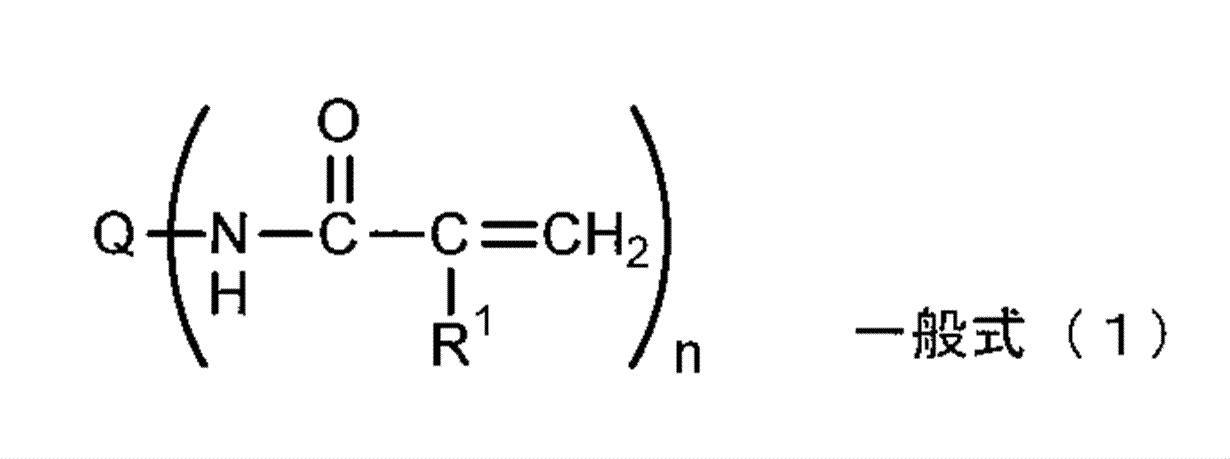
一般式(1)中、Qは、n価の基を表し、R1は、水素原子又はメチル基を表す。また、nは、1以上の整数を表す。
一般式(1)で表される化合物は、不飽和ビニル単量体がアミド結合により基Qに結合したものである。R1は、水素原子又はメチル基を表し、好ましくは水素原子である。基Qの価数nは、重合効率、吐出安定性を向上させる観点から1以上であり、1以上6以下が好ましく、1以上4以下がより好ましい。また、重合効率に優れ、例えば塗工紙を用いたときの塗工層の破壊がより防止される点で、重合性化合物は、n≧2の多官能の(メタ)アクリルアミド化合物を含むことが好ましい。更には、重合性化合物としては、浸透性に優れるn=1である単官能の(メタ)アクリルアミド化合物と、重合効率に優れるn≧2の多官能の(メタ)アクリルアミド化合物とを併用して用いることが好ましい。
また、前記一般式(1)において、n=1である場合の基Qは、(メタ)アクリルアミド構造と連結可能な基であれば特に制限はない。n=1である場合の基Qは、一般式(1)で表される化合物が前述の水溶性を満たすような基から選択されることが好ましい。具体的には以下の化合物群Xから選ばれる化合物から1以上の水素原子又はヒドロキシル基を除いた残基を挙げることができる。
-化合物群X-
エチレングリコール、ジエチレングリコール、トリエチレングリコール、ポリエチレングリコール、プロピレングリコール、ジプロピレングリコール、トリプロピレングリコール、ポリプロピレングリコール、1,3-プロパンジオール、1,2-ブタンジオール、1,3-ブタンジオール、1,4-ブタンジオール、2,3-ブタンジオール、1,5-ペンタンジオール、1,4-ペンタンジオール、2,4-ペンタンジオール、3-メチル-1,5-ペンタンジオール、2-メチル-2,4-ペンタンジオール、1,5-ヘキサンジオール、1,6-ヘキサンジオール、2,5-ヘキサンジオール、グリセリン、1,2,4-ブタントリオール,1,2,6-ヘキサントリオール、1,2,5-ペンタントリオール、チオグリコール、トリメチロールプロパン、ジトリメチロールプロパン、トリメチロールエタン、ジトリメチロールエタン、ネオペンチルグリコール、ペンタエリスリトール、ジペンタエリスリトール、及びこれらの縮合体、低分子ポリビニルアルコール、又は糖類などのポリオール化合物;並びに、
エチレンジアミン、ジエチレントリアミン、トリエチレンテトラミン、ポリエチレンイミン、ポリプロピレンジアミンなどのポリアミン化合物。
エチレングリコール、ジエチレングリコール、トリエチレングリコール、ポリエチレングリコール、プロピレングリコール、ジプロピレングリコール、トリプロピレングリコール、ポリプロピレングリコール、1,3-プロパンジオール、1,2-ブタンジオール、1,3-ブタンジオール、1,4-ブタンジオール、2,3-ブタンジオール、1,5-ペンタンジオール、1,4-ペンタンジオール、2,4-ペンタンジオール、3-メチル-1,5-ペンタンジオール、2-メチル-2,4-ペンタンジオール、1,5-ヘキサンジオール、1,6-ヘキサンジオール、2,5-ヘキサンジオール、グリセリン、1,2,4-ブタントリオール,1,2,6-ヘキサントリオール、1,2,5-ペンタントリオール、チオグリコール、トリメチロールプロパン、ジトリメチロールプロパン、トリメチロールエタン、ジトリメチロールエタン、ネオペンチルグリコール、ペンタエリスリトール、ジペンタエリスリトール、及びこれらの縮合体、低分子ポリビニルアルコール、又は糖類などのポリオール化合物;並びに、
エチレンジアミン、ジエチレントリアミン、トリエチレンテトラミン、ポリエチレンイミン、ポリプロピレンジアミンなどのポリアミン化合物。
さらに、前記基Qとしては、メチレン、エチレン、プロピレン、ブチレン基等の炭素数4以下の置換又は無置換のアルキレン鎖、更にはピリジン環、イミダゾール環、ピラジン環、ピペリジン環、ピペラジン環、モルホリン環などの飽和もしくは不飽和のヘテロ環を有する官能基などを例示することができる。
n=1のとき、基Qとしては、アルキル基又は置換アルキル基が好適であり、アルキルの炭素数は1~5が好ましく、該炭素数は1~3がより好ましい。置換されている場合の置換基としては、例えば、水酸基、アミノ基等が挙げられる。
また、n≧2のとき、基Qは、連結基を表す。連結基としては、オキシアルキレン基(好ましくはオキシエチレン基)を含むポリオール化合物の残基であることが好ましく、オキシアルキレン基(好ましくはオキシエチレン基)を3以上含むポリオール化合物の残基であることが特に好ましい。
また、n≧2のとき、基Qは、連結基を表す。連結基としては、オキシアルキレン基(好ましくはオキシエチレン基)を含むポリオール化合物の残基であることが好ましく、オキシアルキレン基(好ましくはオキシエチレン基)を3以上含むポリオール化合物の残基であることが特に好ましい。
以下、分子内に(メタ)アクリルアミド構造を有する水溶性の重合性化合物の具体例を示す。但し、本発明は、これらに制限されるものではない。
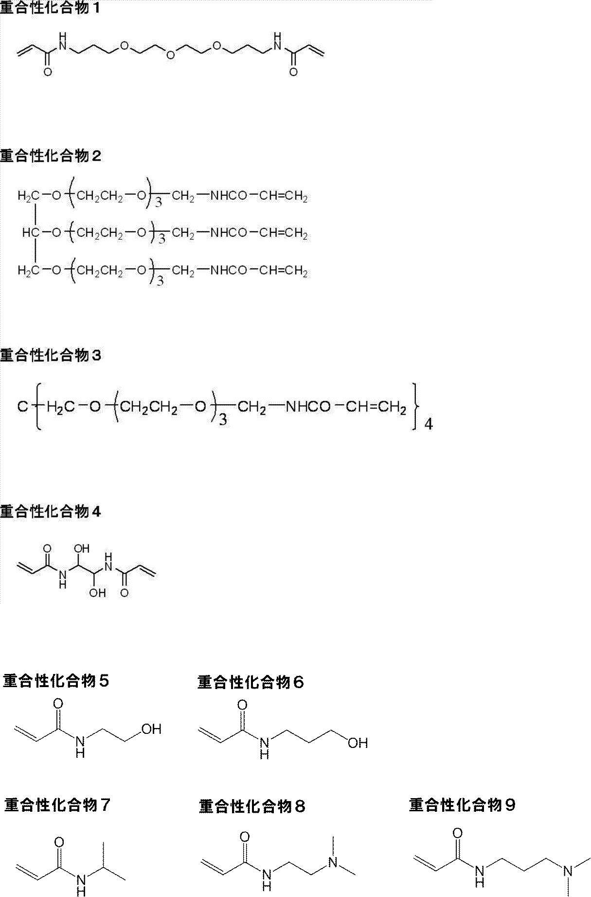
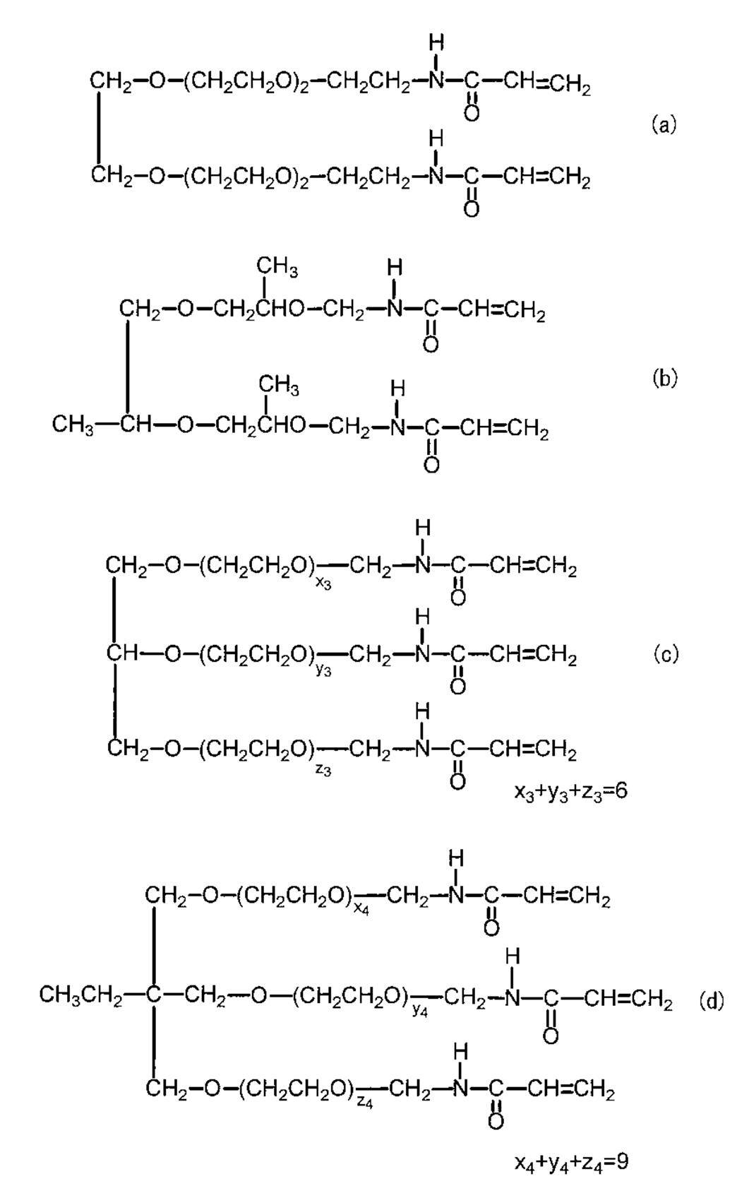
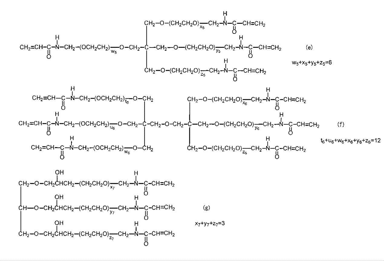
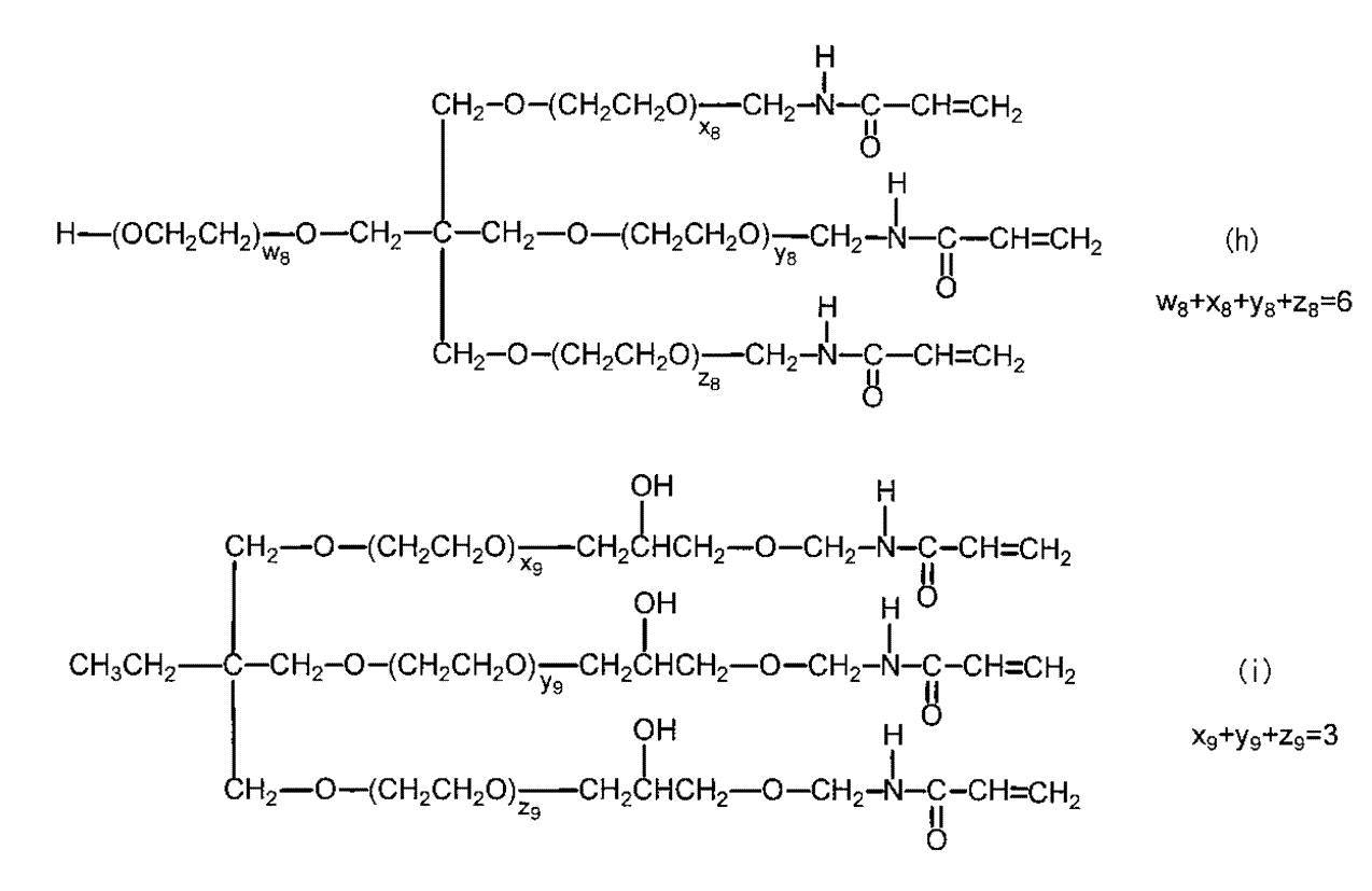
更に、多官能の(メタ)アクリルアミド化合物としては、高い重合能及び硬化能を備え、例えば塗工紙を用いたときの塗工層の破壊を防ぎ、スタッカーブロッキング及び光沢ムラの発生防止効果がより奏される点で、下記一般式(2)で表される4官能の(メタ)アクリルアミド化合物が好ましい。この化合物は、一分子内に重合性基として4つの(メタ)アクリルアミド構造を有する4官能の(メタ)アクリルアミド化合物である。以下では、(メタ)アクリルアミド構造を「(メタ)アクリルアミド基」ともいう。また、この化合物は、例えば、α線、γ線、X線、紫外線、可視光線、赤外光線、電子線等の活性エネルギー線や熱等のエネルギーの付与による重合反応に基づく硬化性を示す。下記一般式(2)で表される化合物は、水溶性を示し、水やアルコール等の水溶性有機溶剤に良好に溶解するものである。
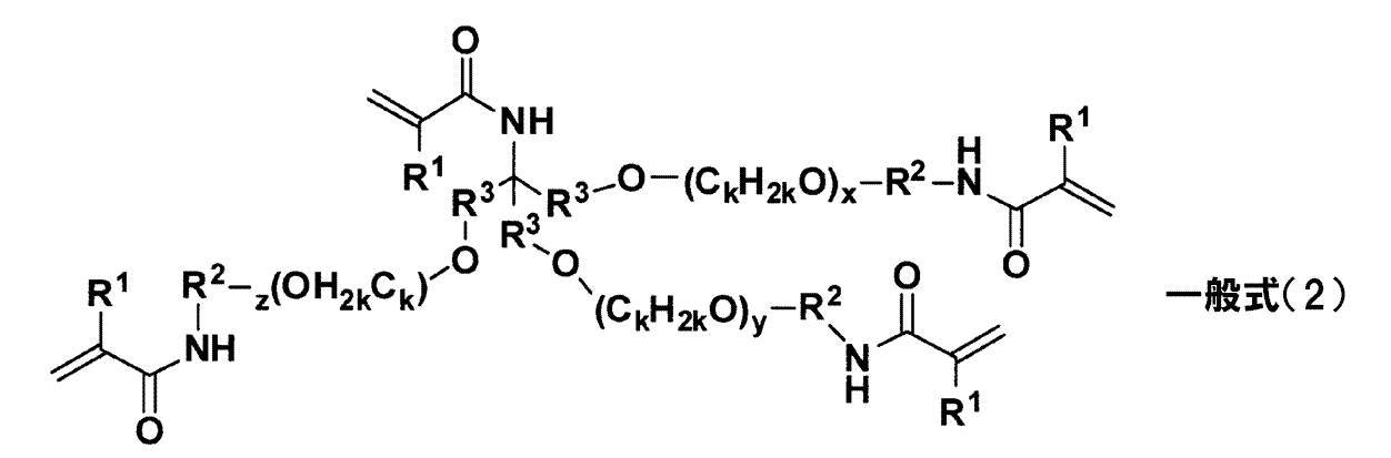
一般式(2)において、R1は、水素原子又はメチル基を表し、水素原子であることが好ましい。複数のR1は、互いに同じでも異なっていてもよい。
R2は、炭素数2~4の直鎖又は分岐のアルキレン基を表す。複数のR2は、互いに同じでも異なっていてもよい。R2は、炭素数3~4のアルキレン基であることが好ましく、炭素数3のアルキレン基であることがより好ましく、炭素数3の直鎖のアルキレン基であることが特に好ましい。R2のアルキレン基は、さらに置換基を有していてもよく、該置換基としてはアリール基、アルコキシ基等が挙げられる。
但し、R2において、R2の両端に結合する酸素原子と窒素原子とがR2の同一の炭素原子に結合した構造をとることはない。R2は、酸素原子と(メタ)アクリルアミド基の窒素原子とを連結する直鎖又は分岐のアルキレン基である。ここで、アルキレン基が分岐構造をとる場合、両端の酸素原子と(メタ)アクリルアミド基の窒素原子とがアルキレン基中の同一の炭素原子に結合した-O-C-N-構造(ヘミアミナール構造)をとることが考えられるが、一般式(2)で表される化合物はこのような構造の化合物を含まない。分子内に-O-C-N-構造を有する化合物は、炭素原子の位置で分解が起こりやすいため、保存中に分解されやすく、インク組成物に含有した場合に保存安定性が低下する要因となる点で好ましくない。
R3は、2価の連結基を表し、複数のR3は、互いに同じでも異なっていてもよい。R3で表される2価の連結基としては、アルキレン基、アリーレン基、複素環基、又はこれらの組み合わせからなる基等が挙げられ、アルキレン基が好ましい。なお、2価の連結基がアルキレン基を含む場合、該アルキレン基中にはさらに-O-、-S-、及び-NRa-から選ばれる少なくとも1種の基が含まれていてもよい。Raは、水素原子又は炭素数1~4のアルキル基を表す。
R3がアルキレン基を含む場合、アルキレン基の例としては、メチレン基、エチレン基、プロピレン基、ブチレン基、ペンチレン基、ヘキシレン基、へプチレン基、オクチレン基、ノニレン基等が挙げられる。R3のアルキレン基の炭素数は、1~6であることが好ましく、1~3であることがさらに好ましく、1であることが特に好ましい。R3のアルキレン基には、さらに-O-、-S-、及び-NRa-から選ばれる少なくとも1種が含まれていてもよい。-O-が含まれるアルキレン基の例としては、-C2H4-O-C2H4-、-C3H6-O-C3H6-等が挙げられる。R3のアルキレン基はさらに置換基を有していてもよく、置換基の例としてはアリール基、アルコキシ基等が挙げられる。
R3がアリーレン基を含む場合、アリーレン基の例としては、フェニレン基、ナフチレン基等が挙げられる、R3のアリーレン基の炭素数は、6~14であることが好ましく、6~10であることがさらに好ましく、6であることが特に好ましい。R3のアリーレン基はさらに置換基を有していてもよく、置換基の例としてはアルキル基、アルコキシ基等が挙げられる。
R3が複素環基を含む場合、複素環基としては、5員または6員環のものが好ましく、それらは更に縮環していてもよい。また、複素環は、芳香族複素環であっても非芳香族複素環であってもよい。複素環基としては、例えば、ピリジン、ピラジン、ピリミジン、ピリダジン、トリアジン、キノリン、イソキノリン、キナゾリン、シンノリン、フタラジン、キノキサリン、ピロール、インドール、フラン、ベンゾフラン、チオフェン、ベンゾチオフェン、ピラゾール、イミダゾール、ベンズイミダゾール、トリアゾール、オキサゾール、ベンズオキサゾール、チアゾール、ベンゾチアゾール、イソチアゾール、ベンズイソチアゾール、チアジアゾール、イソオキサゾール、ベンズイソオキサゾール、ピロリジン、ピペリジン、ピペラジン、イミダゾリジン、チアゾリンなどが挙げられる。中でも、芳香族複素環基が好ましく、ピリジン、ピラジン、ピリミジン、ピリダジン、トリアジン、ピラゾール、イミダゾール、ベンズイミダゾール、トリアゾール、チアゾール、ベンゾチアゾール、イソチアゾール、ベンズイソチアゾール、チアジアゾールが好ましい。なお、上記で示した複素環基は、置換位置を省略した形で例示しているが、置換位置は限定されるものではなく、例えばピリジンであれば、2位、3位、4位で置換することが可能で、これらの置換体を全て含み得るものである。
複素環基は、さらに置換基を有してもよく、置換基の例としては、アルキル基、アリール基、アルコキシ基等が挙げられる。
複素環基は、さらに置換基を有してもよく、置換基の例としては、アルキル基、アリール基、アルコキシ基等が挙げられる。
一般式(2)中のkは、2又は3を表す。複数のkは、互いに同じでも異なっていてもよい。また、CkH2kは、直鎖構造であっても分岐構造であってもよい。
但し、1つのCkH2kO単位内において、kは同一である。
また、x、y、及びzは、各々独立に0~6の整数を表し、0~5の整数であることが好ましく、0~3の整数であることがより好ましい。x+y+zは、0~18を満たし、0~15を満たすことが好ましく、0~9を満たすことがより好ましい。
但し、1つのCkH2kO単位内において、kは同一である。
また、x、y、及びzは、各々独立に0~6の整数を表し、0~5の整数であることが好ましく、0~3の整数であることがより好ましい。x+y+zは、0~18を満たし、0~15を満たすことが好ましく、0~9を満たすことがより好ましい。
上記のうち、複数のR1が各々独立に水素原子又はメチル基を表し、複数のR2が各々独立に炭素数3~4のアルキレン基を表し、複数のR3が各々独立に炭素数1~6(好ましくは炭素数1~3)のアルキレン基を表し、複数のkが各々独立に2又は3を表し、x、y、及びzは、各々独立に0~6の整数を表し、x+y+zが0~15を満たす場合が好ましい。
一般式(2)で表される化合物の具体例を以下に示す。但し、本発明においては、これらに制限されるものではない。
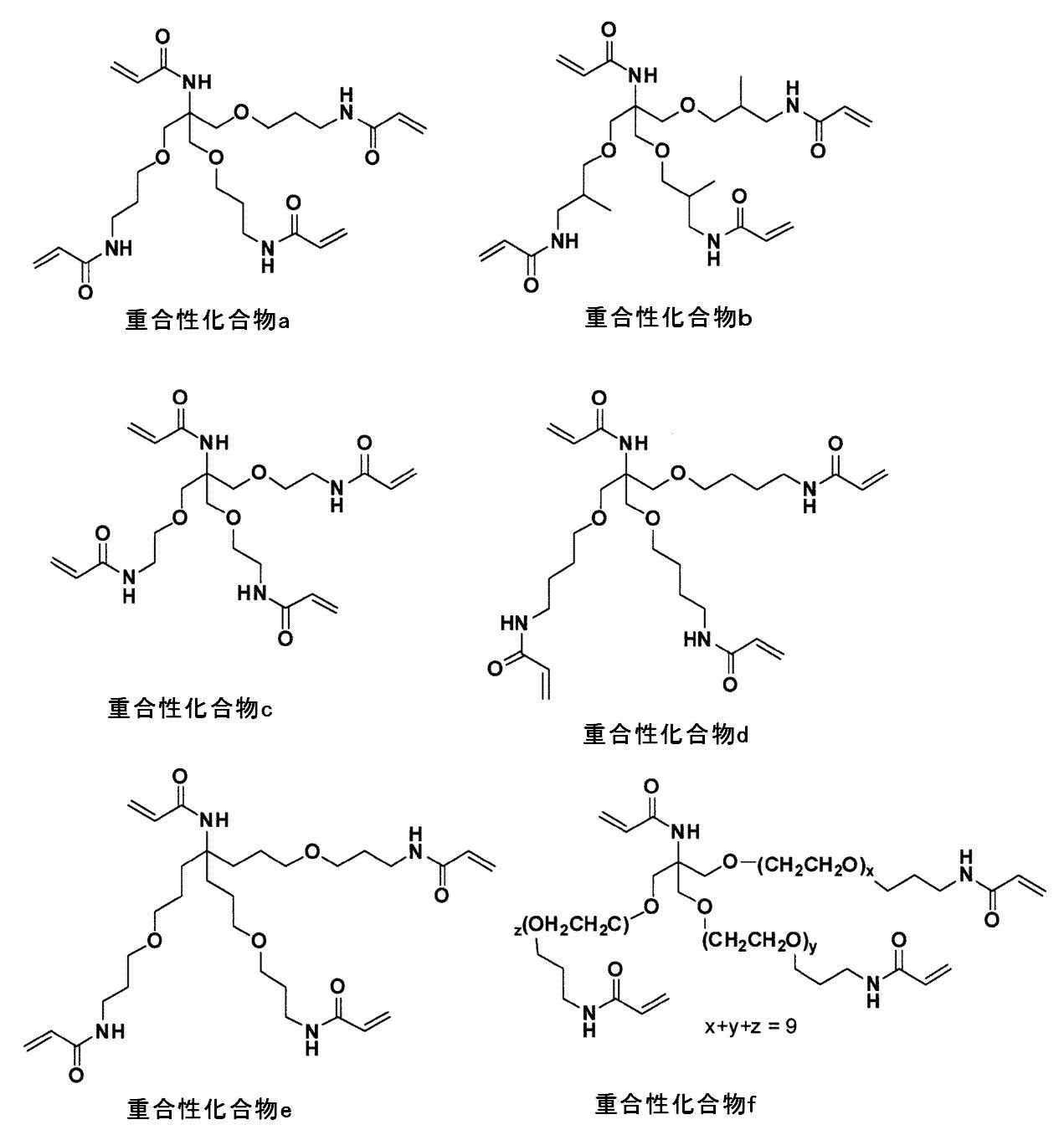
一般式(2)で表される化合物は、例えば下記スキーム1又はスキーム2にしたがって製造することができる。
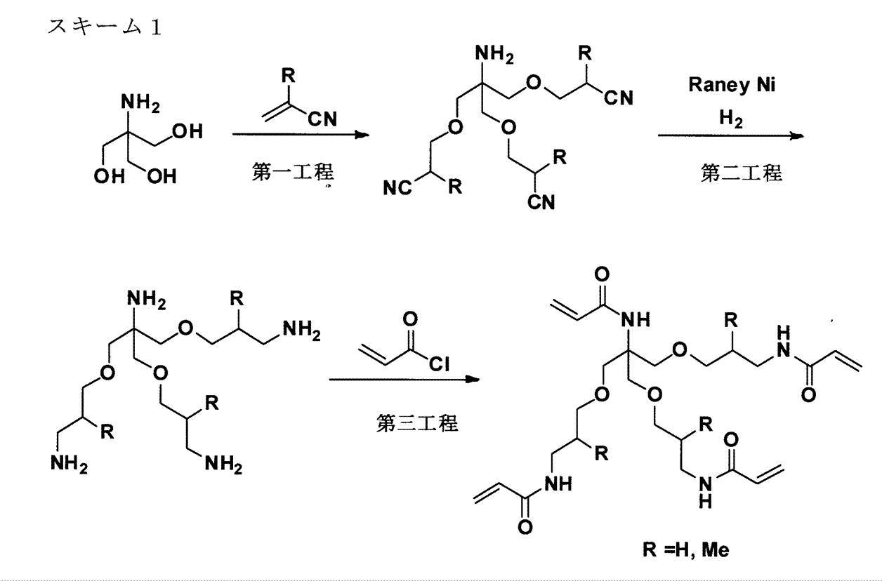
前記スキーム1において、第一工程は、アクリロニトリルとトリスヒドロキシメチルアミノメタンとの反応によりポリシアノ化合物を得る工程である。この工程での反応は、3~60℃で2~8時間行なわれることが好ましい。
第二工程は、ポリシアノ化合物を触媒存在下で水素と反応させ、還元反応によりポリアミン化合物を得る工程である。この工程での反応は、20~60℃で5~16時間行なわれることが好ましい。
第三工程は、ポリアミン化合物とアクリル酸クロリド又はメタクリル酸クロリドとのアシル化反応により多官能アクリルアミド化合物を得る工程である。この工程での反応は、3~25℃で1~5時間行なわれることが好ましい。なお、アシル化剤は、酸クロリドに換えてジアクリル酸無水物又はジメタクリル酸無水物を用いてもよい。なお、アシル化工程で、アクリル酸クロリドとメタクリル酸クロリドの両方を用いることで、最終生成物として同一分子内にアクリルアミド構造とメタクリルアミド構造とを有する化合物を得ることができる。
第二工程は、ポリシアノ化合物を触媒存在下で水素と反応させ、還元反応によりポリアミン化合物を得る工程である。この工程での反応は、20~60℃で5~16時間行なわれることが好ましい。
第三工程は、ポリアミン化合物とアクリル酸クロリド又はメタクリル酸クロリドとのアシル化反応により多官能アクリルアミド化合物を得る工程である。この工程での反応は、3~25℃で1~5時間行なわれることが好ましい。なお、アシル化剤は、酸クロリドに換えてジアクリル酸無水物又はジメタクリル酸無水物を用いてもよい。なお、アシル化工程で、アクリル酸クロリドとメタクリル酸クロリドの両方を用いることで、最終生成物として同一分子内にアクリルアミド構造とメタクリルアミド構造とを有する化合物を得ることができる。

前記スキーム2において、第一工程は、アミノアルコールの窒素原子に、ベンジル基、ベンジルオキシカルボニル基等による保護基導入反応により窒素保護アミノアルコール化合物を得る工程である。この工程での反応は、3~25℃で3~5時間行なわれることが好ましい。
第二工程は、窒素保護アミノアルコール化合物のOH基に、メタンスルホニル基、p-トルエンスルホニル基等の脱離基を導入し、スルホニル化合物を得る工程である。この工程での反応は、3~25℃で2~5時間行なわれることが好ましい。
第三工程は、スルホニル化合物とトリスヒドロキシメチルニトロメタンとのSN2反応により、アミノアルコール付加化合物を得る工程である。この工程での反応は、3~70℃で5~10時間行なわれることが好ましい。
第四工程は、アミノアルコール付加化合物を触媒存在下で水素と反応させ、水素添加反応によりポリアミン化合物を得る工程である。この工程での反応は、20~60℃で5~16時間行なわれることが好ましい。
第五工程は、ポリアミン化合物とアクリル酸クロリド又はメタクリル酸クロリドとのアシル化反応により多官能アクリルアミド化合物を得る工程である。この工程での反応は、3~25℃で1~5時間行なわれることが好ましい。なお、アシル化剤は、酸クロリドに換えてジアクリル酸無水物又はジメタクリル酸無水物を用いてもよい。なお、アシル化工程で、アクリル酸クロリドとメタクリル酸クロリドの両方を用いることで、最終生成物として同一分子内にアクリルアミド構造とメタクリルアミド構造とを有する化合物を得ることができる。
第二工程は、窒素保護アミノアルコール化合物のOH基に、メタンスルホニル基、p-トルエンスルホニル基等の脱離基を導入し、スルホニル化合物を得る工程である。この工程での反応は、3~25℃で2~5時間行なわれることが好ましい。
第三工程は、スルホニル化合物とトリスヒドロキシメチルニトロメタンとのSN2反応により、アミノアルコール付加化合物を得る工程である。この工程での反応は、3~70℃で5~10時間行なわれることが好ましい。
第四工程は、アミノアルコール付加化合物を触媒存在下で水素と反応させ、水素添加反応によりポリアミン化合物を得る工程である。この工程での反応は、20~60℃で5~16時間行なわれることが好ましい。
第五工程は、ポリアミン化合物とアクリル酸クロリド又はメタクリル酸クロリドとのアシル化反応により多官能アクリルアミド化合物を得る工程である。この工程での反応は、3~25℃で1~5時間行なわれることが好ましい。なお、アシル化剤は、酸クロリドに換えてジアクリル酸無水物又はジメタクリル酸無水物を用いてもよい。なお、アシル化工程で、アクリル酸クロリドとメタクリル酸クロリドの両方を用いることで、最終生成物として同一分子内にアクリルアミド構造とメタクリルアミド構造とを有する化合物を得ることができる。
上記の工程を経て得られた化合物は、反応生成液から常法により精製することで得られる。例えば、有機溶媒を用いた分液抽出、貧溶媒を用いた晶析、シリカゲルを用いたカラムクロマトグラフィーなどによって精製できる。
本発明における重合性化合物の例として挙げられるカチオン性の重合性化合物は、カチオン基と不飽和二重結合等の重合性基とを有する化合物である。カチオン性の重合性化合物としては、例えば、エポキシモノマー類、オキタセンモノマー類などを好適に用いることができる。カチオン性の重合性化合物を含有すると、カチオン基を有することでインク組成物のカチオン性が強くなり、アニオン性インクを用いたときの混色がより効果的に防止される。
カチオン性の重合性化合物としては、例えば、N,N-ジメチルアミノエチルメタクリレート、N,N-ジメチルアミノエチルアクリレート、N,N-ジメチルアミノプロピルメタクリレート、N,N-ジメチルアミノプロピルアクリレート、N,N-ジメチルアミノアクリルアミド、N,N-ジメチルアミノメタアクリルアミド、N,N-ジメチルアミノエチルアクリルアミド、N,N-ジメチルアミノエチルメタアクリルアミド、N,N-ジメチルアミノプロピルアクリルアミド、およびN,N-ジメチルアミノプロピルメタアクリルアミド、ならびにこれらの4級化化合物などが挙げられる。
エポキシモノマー類としては、例えば、多価アルコールのグリシジルエーテル、グリシジルエステル、脂肪族環状のエポキシドなどが挙げられる。
さらに、カチオン性の重合性化合物の例として、下記構造を有するものを挙げることができる。
カチオン性の重合性化合物としては、例えば、N,N-ジメチルアミノエチルメタクリレート、N,N-ジメチルアミノエチルアクリレート、N,N-ジメチルアミノプロピルメタクリレート、N,N-ジメチルアミノプロピルアクリレート、N,N-ジメチルアミノアクリルアミド、N,N-ジメチルアミノメタアクリルアミド、N,N-ジメチルアミノエチルアクリルアミド、N,N-ジメチルアミノエチルメタアクリルアミド、N,N-ジメチルアミノプロピルアクリルアミド、およびN,N-ジメチルアミノプロピルメタアクリルアミド、ならびにこれらの4級化化合物などが挙げられる。
エポキシモノマー類としては、例えば、多価アルコールのグリシジルエーテル、グリシジルエステル、脂肪族環状のエポキシドなどが挙げられる。
さらに、カチオン性の重合性化合物の例として、下記構造を有するものを挙げることができる。
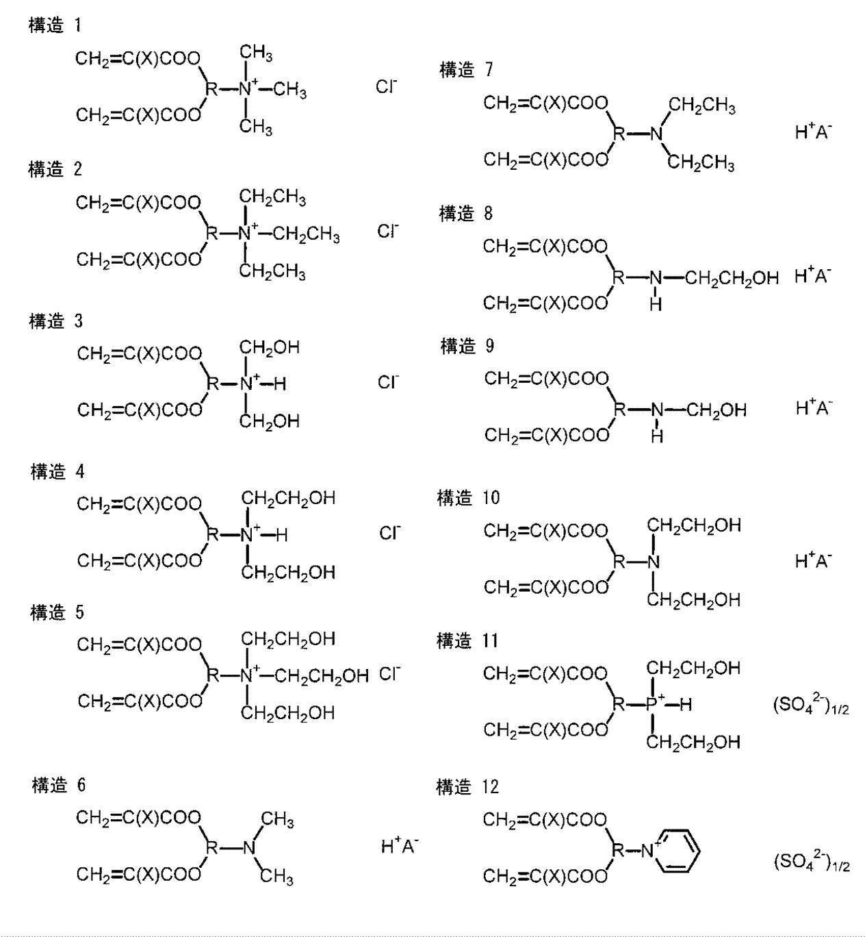
上記の構造において、Rは、ポリオールの残基を表す。また、Xは、H又はCH3を表し、A-はCl-、HSO3
-又はCH3COO-を表す。このポリオールを導入するための化合物としては、例えば、グリセリン、1,2,4-ブタントリオール、1,2,5-ペンタントリオール、1,2,6-ヘキサントリオール、トリメチロールプロパン、トリメチロールメタン、トリメチロールエタン、ペンタエリスリトール、ビスフェノールA、および脂環型ビスフェノールA、ならびにこれらの縮合物等を挙げることができる。
以下、カチオン基を有する重合性化合物の具体例(カチオン性化合物1~11)を例示する。
以下、カチオン基を有する重合性化合物の具体例(カチオン性化合物1~11)を例示する。

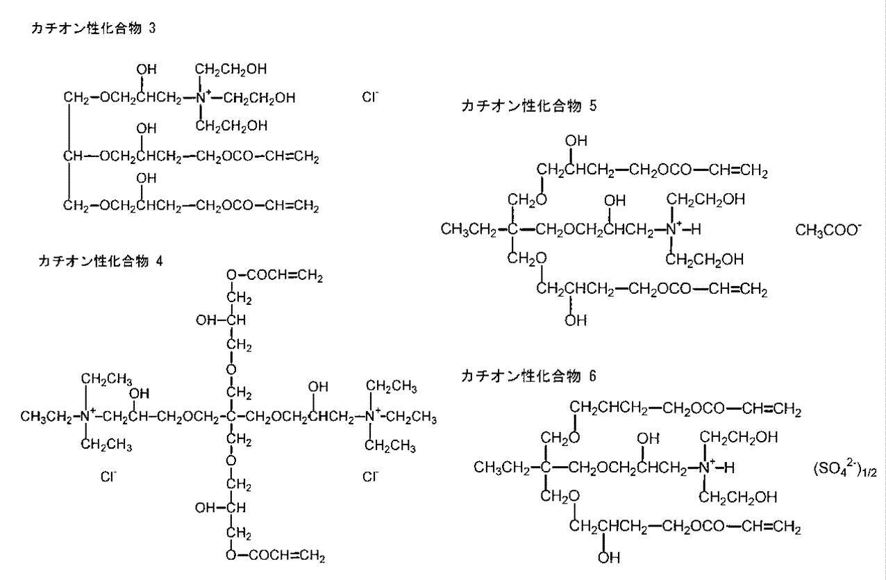


本発明における重合性化合物としては、擦過耐性のほか、画像の光沢ムラ及びスタッカーブロッキングの発生防止効果を高め得る観点から、多官能のモノマーが好ましく、2官能~6官能のモノマーが好ましく、溶解性と擦過耐性の両立の観点から、2官能~4官能のモノマーが好ましい。
本発明における重合性化合物(p)と既述の着色剤(q)との含有比率〔q:p[質量比]〕としては、1:1~1:20が好ましく、より好ましくは2:3~1:15であり、更に好ましくは1:2~1:10である。含有比率(q:p)が1:1以上、すなわち重合性化合物の割合が着色剤に比べて少なすぎない範囲であると、画像の密着性により優れる。また、含有比率(q:p)が1:20以下、すなわち重合性化合物の割合が着色剤に比べて多すぎない範囲であると、吐出性の点で有利である。
重合性化合物は、1種単独又は2種以上を組み合わせて含有することができる。
前記重合性化合物のインク組成物中における含有量としては、インク組成物の総質量に対して、15質量%以上30質量%未満が好ましく、15質量%以上25質量%以下がより好ましい。重合性化合物の含有量が15質量%以上であると、インク組成物の記録媒体との密着性が向上すると共に、画像強度がより高まって画像の耐擦過性、光沢性、耐スタッカーブロッキング性に優れる。重合性化合物の含有量が30質量%以下であると、画像の段差(パイルハイト)の点で有利である。
前記重合性化合物のインク組成物中における含有量としては、インク組成物の総質量に対して、15質量%以上30質量%未満が好ましく、15質量%以上25質量%以下がより好ましい。重合性化合物の含有量が15質量%以上であると、インク組成物の記録媒体との密着性が向上すると共に、画像強度がより高まって画像の耐擦過性、光沢性、耐スタッカーブロッキング性に優れる。重合性化合物の含有量が30質量%以下であると、画像の段差(パイルハイト)の点で有利である。
[光重合開始剤]
本発明におけるインク組成物は、活性エネルギー線により重合性化合物の重合を開始する重合開始剤の少なくとも1種を含有してもよい。重合開始剤は、1種単独で又は2種以上を混合して、あるいは増感剤と併用して使用することができる。
本発明におけるインク組成物は、活性エネルギー線により重合性化合物の重合を開始する重合開始剤の少なくとも1種を含有してもよい。重合開始剤は、1種単独で又は2種以上を混合して、あるいは増感剤と併用して使用することができる。
重合開始剤は、活性エネルギー線により重合性化合物の重合反応を開始し得る化合物を適宜選択して含有することができる。重合開始剤の例として、放射線もしくは光、又は電子線により活性種(ラジカル、酸、塩基など)を発生する重合開始剤(例えば光重合開始剤等)が挙げられる。
光重合開始剤としては、例えば、アセトフェノン、2,2-ジエトキシアセトフェノン、p-ジメチルアミノアセトフェン、p-ジメチルアミノプロピオフェノン、ベンゾフェノン、2-クロロベンゾフェノン、p,p’-ジクロロベンゾフェン、p,p’-ビスジエチルアミノベンゾフェノン、ミヒラーケトン、ベンジル、ベンゾイン、ベンゾインメチルエーテル、ベンゾインエチルエーテル、ベンゾインイソプロピルエーテル、ベンゾインn-プロピルエーテル、ベンゾインイソブチルエーテル、ベンゾインn-ブチルエーテル、ベンジルジメチルケタール、テトラメチルチウラムモノサルファイド、チオキサントン、2-クロロチオキサントン、2-メチルチオキサントン、アゾビスイソブチロニトリル、ベンゾインパーオキサイド、ジ-tert-ブチルパーオキサイド、1-ヒドロキシシクロヘキシルフェニルケトン、1-[4-(2-ヒドロキシエトキシ)-フェニル]-2-ヒドロキシ-2-メチル-1-プロパン-1-オン、2-ヒドロキシ-2-メチル-1-フェニル-1-オン、1-(4-イソプロピルフェニル)-2-ヒドロキシ-2-メチルプロパン-1-オン、メチルベンゾイルフォーメートが挙げられる。更に、例えばトリフェニルスルホニウムヘキサフルオロホスフェート、ジフェニルヨードニウムヘキサフルオロアンチモネート等の、芳香族ジアゾニウム塩、芳香族ハロニウム塩、芳香族スルホニウム塩、メタロセン化合物等が挙げられる。中でも、インクとの相溶性が高く光沢ムラが低減する点で、1-[4-(2-ヒドロキシエトキシ)-フェニル]-2-ヒドロキシ-2-メチル-1-プロパン-1-オンが好ましい。
本発明のインク組成物が重合開始剤を含有する場合、重合開始剤のインク組成物中における含有量としては、既述の重合性化合物に対して、1~40質量%が好ましく、1~10質量%がより好ましい。重合開始剤の含有量は、1質量%以上であると画像の耐擦過性、耐傷性がより向上し、高速記録に有利であり、40質量%以下であると吐出安定性の点で有利である。
前記増感剤としては、アミン系(脂肪族アミン、芳香族基を含むアミン、ピペリジンなど)、尿素(アリル系、o-トリルチオ尿素など)、イオウ化合物(ナトリウムジエチルジチオホスフェート、芳香族スルフィン酸の可溶性塩など)、ニトリル系化合物(N,N,ジ置換p-アミノベンゾニトリルなど)、リン化合物(トリn-ブチルホスフィン、ネトリウムジエチルジチオホスフィードなど)、窒素化合物(ミヒラーケトン、N-ニトリソヒドロキシルアミン誘導体、オキサゾリジン化合物、テトラヒドロ1,3オキサジン化合物、ホルムアルデヒド、アセトアルデヒドとジアミンの縮合物など)、塩素化合物(四塩化炭素、ヘキサクロロエタンなど)、エポキシ樹脂とアミンの反応生成物の高分子化アミン、トリエタノールアミントリアクリレート、等が挙げられる。
増感剤は、本発明の効果を損なわない範囲で含有することができる。
増感剤は、本発明の効果を損なわない範囲で含有することができる。
[水]
本発明におけるインク組成物は、水を含有するものであるが、水の量には特に制限はない。中でも、水の好ましい含有量は、インク組成物の全質量に対し、10~99質量%であり、より好ましくは30~80質量%であり、更に好ましくは50~70質量%である。
本発明におけるインク組成物は、水を含有するものであるが、水の量には特に制限はない。中でも、水の好ましい含有量は、インク組成物の全質量に対し、10~99質量%であり、より好ましくは30~80質量%であり、更に好ましくは50~70質量%である。
[水溶性有機溶剤]
本発明におけるインク組成物は、水溶性有機溶剤を含有していてもよい。水溶性有機溶剤を含有する場合、その含有量は少ないことが好ましく、インク組成物の全質量に対して3質量%未満が好ましい。水溶性有機溶剤の含有量の下限は、重合性化合物の溶解性向上の点で、インク組成物の全質量に対し、0.5質量%が望ましい。
本発明におけるインク組成物は、水溶性有機溶剤を含有していてもよい。水溶性有機溶剤を含有する場合、その含有量は少ないことが好ましく、インク組成物の全質量に対して3質量%未満が好ましい。水溶性有機溶剤の含有量の下限は、重合性化合物の溶解性向上の点で、インク組成物の全質量に対し、0.5質量%が望ましい。
水溶性有機溶剤を含有することで、インク組成物の乾燥防止、湿潤又は紙への浸透促進の効果が得られる。前記水溶性有機溶剤としては、例えば、グリセリン、1,2,6-ヘキサントリオール、トリメチロールプロパン、エチレングリコール、プロピレングリコール、ジエチレングリコール、トリエチレングリコール、テトラエチレングリコール、ペンタエチレングリコール、ジプロピレングリコール等のグリコール類や、2-ブテン-1,4-ジオール、2-エチル-1,3-ヘキサンジオール、2-メチル-2,4-ペンタンジオール、1,2-オクタンジオール、1,2-ヘキサンジオール、1,2-ペンタンジオール、4-メチル-1,2-ペンタンジオール等のアルカンジオールなどの多価アルコール類;エチレングリコールモノメチルエーテル、エチレングリコールモノエチルエーテル、エチレングリコールモノブチルエーテル、エチレングリコールモノメチルエーテルアセテート、ジエチレングリコールモノメチルエーテル、ジエチレングリコールモノエチルエーテルなどのグリコールエーテル類;並びに、特開2011-42150号公報の段落番号[0116]に記載の、糖類や糖アルコール類、ヒアルロン酸類、炭素数1~4のアルキルアルコール類、他のグリコールエーテル類、2-ピロリドン、N-メチル-2-ピロリドン等が挙げられる。これらの水溶性有機溶剤は、1種又は2種以上を組み合わせて用いることができる。多価アルコール類は、乾燥防止剤や湿潤剤としても有用であり、また、浸透剤として好ましい。その具体例としては、特開2011-42150号公報の段落番号[0117]に記載の脂肪族ジオール等が挙げられる。
上記のほか、水溶性有機溶剤として下記構造式(1)で表される化合物(グリセリンのアルキレンオキシド付加物)が挙げられる。
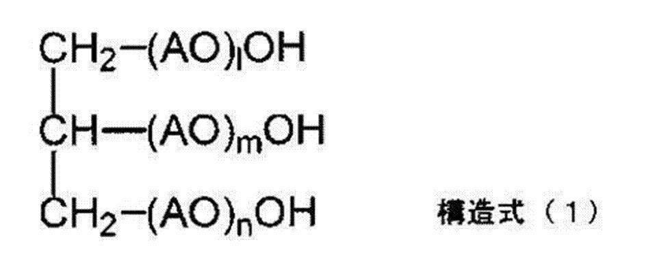
構造式(1)において、l、m、及びnは、それぞれ独立に、1以上の整数を表しかつl+m+n=3~15を満たす。中でも、l+m+nは、3以上であると記録媒体に対するカール抑制効果が得られ、15以下であるとインク組成物の吐出性を良好に維持することができる。中でも、l+m+nは、3~12が好ましく、3~10がより好ましい。構造式(1)において、AOは、エチレンオキシ基(EOと略記することがある)及び/又はプロピレンオキシ基(POと略記することがある)を表し、中でもプロピレンオキシ基が好ましい。構造式中の(AO)l、(AO)m、及び(AO)nの各AOは、それぞれ同一でも異なってもよい。
構造式(1)で表される化合物の詳細については、特開2011-42150号公報の段落番号[0121]~[0125]に記載されている。グリセリンのアルキレンオキシド付加物は、上市されている市販品を用いてもよく、例えば、ポリオキシプロピル化グリセリン(ポリプロピレングリコールとグリセリンとのエーテル)として、サンニックスGP-250(平均分子量250)、同GP-400(平均分子量400)、同GP-600(平均分子量600)〔以上、三洋化成工業(株)製〕、及び同公報の段落番号[0126]に記載の例が挙げられる。
[界面活性剤]
本発明におけるインク組成物は、必要に応じて、界面活性剤の少なくとも1種を含むことができる。界面活性剤は、例えば表面張力調整剤として用いることができる。
前記界面活性剤としては、分子内に親水部と疎水部を合わせ持つ構造を有する化合物等を有効に使用することができ、アニオン性界面活性剤、カチオン性界面活性剤、両性界面活性剤、ノニオン性界面活性剤、ベタイン系界面活性剤のいずれも使用することができる。更に、上記の水溶性ポリマー(高分子分散剤)を界面活性剤としても用いてもよい。
本発明におけるインク組成物は、必要に応じて、界面活性剤の少なくとも1種を含むことができる。界面活性剤は、例えば表面張力調整剤として用いることができる。
前記界面活性剤としては、分子内に親水部と疎水部を合わせ持つ構造を有する化合物等を有効に使用することができ、アニオン性界面活性剤、カチオン性界面活性剤、両性界面活性剤、ノニオン性界面活性剤、ベタイン系界面活性剤のいずれも使用することができる。更に、上記の水溶性ポリマー(高分子分散剤)を界面活性剤としても用いてもよい。
本発明においては、インクの打滴干渉抑制の観点から、ノニオン性界面活性剤が好ましく、アセチレングリコール誘導体(アセチレングリコール系界面活性剤)がより好ましい。前記アセチレングリコール系界面活性剤としては、例えば、2,4,7,9-テトラメチル-5-デシン-4,7-ジオール及び2,4,7,9-テトラメチル-5-デシン-4,7-ジオールのアルキレンオキシド付加物等を挙げることができ、これらから選ばれる少なくとも1種であることが好ましい。これらの化合物の市販品としては例えば、日信化学工業社のオルフィンE1010などのEシリーズを挙げることができる。
界面活性剤(表面張力調整剤)をインク組成物に含有する場合、界面活性剤は、インクジェット法でインク組成物の吐出を良好に行う観点から、インク組成物の表面張力を20~60mN/mに調整できる範囲の量にて含有されることが好ましい。また、表面張力の点からは、界面活性剤は、20~45mN/m(好ましくは25~40mN/m)に調整できる範囲の量にて含有されることが好ましい。
具体的には、本発明のインク組成物が界面活性剤を含む場合、界面活性剤のインク組成物中における含有量は、インク組成物の全量に対して、0.1質量%以上が好ましく、より好ましくは0.1~10質量%であり、更に好ましくは0.2~3質量%である。
具体的には、本発明のインク組成物が界面活性剤を含む場合、界面活性剤のインク組成物中における含有量は、インク組成物の全量に対して、0.1質量%以上が好ましく、より好ましくは0.1~10質量%であり、更に好ましくは0.2~3質量%である。
[他の成分]
本発明におけるインク組成物は、上記成分以外にその他の添加剤を含んでいてもよい。その他の添加剤としては、例えば、重合禁止剤、乾燥防止剤(湿潤剤)、褪色防止剤、乳化安定剤、浸透促進剤、紫外線吸収剤、防腐剤、防黴剤、pH調整剤、表面張力調整剤、消泡剤、粘度調整剤、分散安定剤、防錆剤、キレート剤等の公知の添加剤が挙げられる。これらの各種添加剤は、インク組成物の場合はインクに直接添加し、また、油性染料を分散物として用いる場合は染料分散物の調製後に分散物に添加するのが一般的であるが、調製時に油相又は水相に添加してもよい。
本発明におけるインク組成物は、上記成分以外にその他の添加剤を含んでいてもよい。その他の添加剤としては、例えば、重合禁止剤、乾燥防止剤(湿潤剤)、褪色防止剤、乳化安定剤、浸透促進剤、紫外線吸収剤、防腐剤、防黴剤、pH調整剤、表面張力調整剤、消泡剤、粘度調整剤、分散安定剤、防錆剤、キレート剤等の公知の添加剤が挙げられる。これらの各種添加剤は、インク組成物の場合はインクに直接添加し、また、油性染料を分散物として用いる場合は染料分散物の調製後に分散物に添加するのが一般的であるが、調製時に油相又は水相に添加してもよい。
~インク組成物の物性~
本発明におけるインク組成物の表面張力(25℃)は、特に限定されるものではないが、20mN/m以上60mN/m以下が好ましい。より好ましい表面張力は、20mN/m以上45mN/m以下であり、更に好ましくは25mN/m以上40mN/m以下である。インク組成物の表面張力は、Automatic Surface Tensiometer CBVP-Z(協和界面科学株式会社製)を用い、25℃の条件下で測定される。
本発明におけるインク組成物の粘度は、特に限定されるものではないが、25℃下で1.2mPa・s以上15.0mPa・s以下が好ましく、より好ましくは2mPa・s以上13mPa・s未満であり、更に好ましくは2.5mPa・s以上10mPa・s未満である。インク組成物の粘度は、VISCOMETER TV-22(TOKI SANGYO CO.LTD製)を用い、25℃の条件下で測定される。
また、本発明におけるインク組成物のpHは、特に制限されるものではないが、インク安定性と凝集速度の観点から、7.5~10の範囲が好ましく、8~9の範囲がより好ましい。尚、インク組成物のpHは25℃で、通常用いられるpH測定装置(例えば、東亜ディーケーケー(株)製、マルチ水質計MM-60R)によって測定される。インク組成物のpHは、酸性化合物又は塩基性化合物を用いて適宜調整することがでる。酸性化合物及び塩基性化合物としては、通常用いられる化合物を特に制限なく用いることができる。
本発明におけるインク組成物の表面張力(25℃)は、特に限定されるものではないが、20mN/m以上60mN/m以下が好ましい。より好ましい表面張力は、20mN/m以上45mN/m以下であり、更に好ましくは25mN/m以上40mN/m以下である。インク組成物の表面張力は、Automatic Surface Tensiometer CBVP-Z(協和界面科学株式会社製)を用い、25℃の条件下で測定される。
本発明におけるインク組成物の粘度は、特に限定されるものではないが、25℃下で1.2mPa・s以上15.0mPa・s以下が好ましく、より好ましくは2mPa・s以上13mPa・s未満であり、更に好ましくは2.5mPa・s以上10mPa・s未満である。インク組成物の粘度は、VISCOMETER TV-22(TOKI SANGYO CO.LTD製)を用い、25℃の条件下で測定される。
また、本発明におけるインク組成物のpHは、特に制限されるものではないが、インク安定性と凝集速度の観点から、7.5~10の範囲が好ましく、8~9の範囲がより好ましい。尚、インク組成物のpHは25℃で、通常用いられるpH測定装置(例えば、東亜ディーケーケー(株)製、マルチ水質計MM-60R)によって測定される。インク組成物のpHは、酸性化合物又は塩基性化合物を用いて適宜調整することがでる。酸性化合物及び塩基性化合物としては、通常用いられる化合物を特に制限なく用いることができる。
-乾燥工程-
本発明における乾燥工程は、インク付与工程で形成された画像を乾燥させる工程である。乾燥工程では、インク付与工程でのインク組成物の付与により記録媒体に形成された画像(インク組成物)中の水の少なくとも一部及び水溶性有機溶剤の少なくとも一部を乾燥除去する。乾燥工程を後述の硬化工程の前に設け、インク組成物中の水や水溶性有機溶剤の含有量を減らすことで、硬化工程での重合性化合物の硬化反応がより良好に進行する。特に、主走査方向にインクを吐出して1回の走査で1ラインを形成するシングルパス方式により画像形成する方法など、高速で画像形成する場合に、画像形成性が成り立つ感度を確保することができる。
本発明における乾燥工程は、インク付与工程で形成された画像を乾燥させる工程である。乾燥工程では、インク付与工程でのインク組成物の付与により記録媒体に形成された画像(インク組成物)中の水の少なくとも一部及び水溶性有機溶剤の少なくとも一部を乾燥除去する。乾燥工程を後述の硬化工程の前に設け、インク組成物中の水や水溶性有機溶剤の含有量を減らすことで、硬化工程での重合性化合物の硬化反応がより良好に進行する。特に、主走査方向にインクを吐出して1回の走査で1ラインを形成するシングルパス方式により画像形成する方法など、高速で画像形成する場合に、画像形成性が成り立つ感度を確保することができる。
例えば記録媒体の搬送速度を100~3000mm/secとして画像形成する場合に、良好な硬化反応が得られ、光沢ムラ及びスタッカーブロッキングの発生防止効果がより奏される。更には、搬送速度が150~2700mm/sec、より好ましくは250~2500mm/secである場合に、乾燥工程を設けたことによる記録媒体との密着性、光沢性、耐スタッカーブロッキング性の向上効果に優れる。
本発明における乾燥工程においては、必ずしも水や水溶性有機溶剤を完全に乾燥させる必要はなく、水や水溶性有機溶剤が画像中及び記録媒体(特に塗工紙を用いたときの塗工層(顔料層))中に残存してもよい。乾燥工程では、むしろUV硬化反応を損なわない範囲で残存する程度に乾燥させることが好ましい。
乾燥工程では、最大付与量で付与されたインク組成物(画像)に含まれる水のうち、60~80質量%が除去される乾燥条件(以下、「乾燥量」ということがある。)で、前記インク付与工程で記録媒体上に付与されたインク組成物中に含まれる水及び/又は水溶性有機溶剤の少なくとも一部が除去されることが好ましい。除去される水及び/又は水溶性有機溶剤の量が60質量%以上であると、スタッカーブロッキングの発生が抑制される。また、除去される水の量が80質量%以下であると、画像の密着性が良好である。
乾燥条件は、必要に応じて適宜設定されるインク付与工程におけるインク組成物の最大付与量に基づいて設定されてもよい。かかる乾燥条件下で顔料を含むインク組成物中の水を除去することで、スタッカーブロッキングの発生が抑制され、密着性に優れた画像が得られる。
乾燥工程における乾燥量は、以下のようにして算出することができる。すなわち、
乾燥工程を設けずにインクの最大付与量で形成した画像に含まれる水分量W0と、所定の乾燥条件による乾燥工程を設けてインクの最大付与量で形成した画像に含まれる水分量W1とをそれぞれ測定する。次いで、W0とW1との差の、W0に対する比率((W0-W1)/W0×100[質量%])を求めることで、乾燥工程によって除去される水分量としての乾燥量(質量%)が算出される。
なお、画像に含まれる水分量は、カールフィッシャー法により測定される。本発明における水分量としては、カールフィッシャー水分計MKA-520(京都電子工業(株)製)を用い、通常の測定条件で測定した水分量を適用する。
乾燥工程を設けずにインクの最大付与量で形成した画像に含まれる水分量W0と、所定の乾燥条件による乾燥工程を設けてインクの最大付与量で形成した画像に含まれる水分量W1とをそれぞれ測定する。次いで、W0とW1との差の、W0に対する比率((W0-W1)/W0×100[質量%])を求めることで、乾燥工程によって除去される水分量としての乾燥量(質量%)が算出される。
なお、画像に含まれる水分量は、カールフィッシャー法により測定される。本発明における水分量としては、カールフィッシャー水分計MKA-520(京都電子工業(株)製)を用い、通常の測定条件で測定した水分量を適用する。
乾燥工程で除去されるインク組成物中の水量(乾燥量)は、乾燥後の硬化効率が良好に保たれる点から、最大付与量を15ml/m2以下として付与されたインク組成物の全水分量に対して、60~80質量%が好ましく、65~80質量%がより好ましく、70~80質量%が更に好ましい。
また、乾燥は、前記インク組成物の液滴が記録媒体に着弾した時点から5秒以内に開始されることが好ましい。ここで、「着弾した時点から5秒以内」とは、インク滴の着弾時から5秒以内に、画像に送風されるか又は熱が与えられることを意味する。例えば、インク滴の着弾から5秒以内に乾燥領域内に記録媒体を搬送することで、着弾から5秒以内に乾燥が開始される。
インク滴の着弾から乾燥開始までの時間は、3秒以内がより好ましい。
インク滴の着弾から乾燥開始までの時間は、3秒以内がより好ましい。
乾燥は、ニクロム線ヒータ等の発熱体で加熱する加熱手段、ドライヤ等の送風を利用した送風手段、あるいはこれらを組み合わせた手段により行なえる。加熱方法としては、例えば、記録媒体の画像形成面と反対側からヒータ等で熱を与える方法や、記録媒体の画像形成面に温風又は熱風をあてる方法、赤外線ヒータを用いた加熱法などが挙げられる。加熱は、これらを複数組み合わせて行なってもよい。
-硬化工程-
本発明における硬化工程は、上述の乾燥工程で乾燥された後の画像に活性エネルギー線を照射することで画像を硬化させる工程である。活性エネルギー線を照射することで、インク組成物中の重合性化合物が重合して、顔料を含む硬化膜を形成する。
本発明における硬化工程は、上述の乾燥工程で乾燥された後の画像に活性エネルギー線を照射することで画像を硬化させる工程である。活性エネルギー線を照射することで、インク組成物中の重合性化合物が重合して、顔料を含む硬化膜を形成する。
活性エネルギー線は、重合性化合物を重合可能なものであれば、特に制限はなく、α線、γ線、電子線、X線、紫外線、可視光、赤外光などが挙げられる。中でも、汎用性の観点から、紫外線が好ましい。また、活性エネルギー線の発生源として、例えば、紫外線照射ランプ(ハロゲンランプ、高圧水銀灯など)、レーザー、LED、電子線照射装置などが挙げられる。
照射は、活性エネルギー線を照射する光源を記録媒体の記録面に対向配置し、記録面の全体を照射すれば、画像全体の硬化を行なうことができる。硬化工程は、少なくともインク付与工程の後に設けられるが、インク付与工程及び処理液付与工程の後に設けられることが好ましい。
活性エネルギー線の照射条件としては、重合性化合物が重合反応を起こして硬化可能であれば特に制限はない。
活性エネルギー線の波長は、200~600nmの範囲が好ましく、300~450nmの範囲がより好ましく、350~420nmの範囲が更に好ましい。
活性エネルギー線の出力は、5000mJ/cm2以下であることが好ましく、10~4000mJ/cm2であることがより好ましく、20~3000mJ/cm2であることがさらに好ましい。
活性エネルギー線の波長は、200~600nmの範囲が好ましく、300~450nmの範囲がより好ましく、350~420nmの範囲が更に好ましい。
活性エネルギー線の出力は、5000mJ/cm2以下であることが好ましく、10~4000mJ/cm2であることがより好ましく、20~3000mJ/cm2であることがさらに好ましい。
-冷却工程-
本発明における冷却工程は、硬化工程で硬化した後の画像を、冷却前後での温度差を15℃以上として冷却する工程である。本発明においては、乾燥工程で一旦加熱し、加熱後ある程度の温度(例えば60℃~70℃)を維持しながら硬化させた後、排紙集積部での集積前にあらかじめ画像を冷却する。
本発明における冷却工程は、硬化工程で硬化した後の画像を、冷却前後での温度差を15℃以上として冷却する工程である。本発明においては、乾燥工程で一旦加熱し、加熱後ある程度の温度(例えば60℃~70℃)を維持しながら硬化させた後、排紙集積部での集積前にあらかじめ画像を冷却する。
本発明における冷却工程では、冷却前後の温度差(すなわち冷却前の画像温度と冷却後の画像温度との差)が15℃以上となるように画像を冷却する。ここで、冷却前の画像温度は、硬化工程で画像への照射を終了した時点での画像の温度(℃)をさす。また、冷却後の画像温度は、下記の集積工程で記録媒体が集積(スタック)された時点(集積直後)での画像の温度(℃)をさす。
冷却前後の温度差が15℃に満たない冷却条件では、積み重ねられた状態で荷重がかかった際の画像の変形、すなわち画像の接触面積の増大を防止し得ず、画像中の光沢ムラ、及び画像のクッツキ、ひいてはスタッカーブロッキングの発生を防ぐことができない。冷却前後の温度差としては、上記同様の理由から、20℃以上であるのが好ましく、25℃以上であるのがより好ましい。また、冷却前後の温度差の上限値は、50℃が好ましい。温度差の上限値が50℃以下であることで、収縮による画像部の過度な変形を抑制できる利点がある。
上記した画像温度は、被測定対象である画像の表面に熱電対を接触させて測定される値である。
冷却前後の温度差が15℃に満たない冷却条件では、積み重ねられた状態で荷重がかかった際の画像の変形、すなわち画像の接触面積の増大を防止し得ず、画像中の光沢ムラ、及び画像のクッツキ、ひいてはスタッカーブロッキングの発生を防ぐことができない。冷却前後の温度差としては、上記同様の理由から、20℃以上であるのが好ましく、25℃以上であるのがより好ましい。また、冷却前後の温度差の上限値は、50℃が好ましい。温度差の上限値が50℃以下であることで、収縮による画像部の過度な変形を抑制できる利点がある。
上記した画像温度は、被測定対象である画像の表面に熱電対を接触させて測定される値である。
冷却後の画像温度、すなわち集積直後の画像の温度としては、スタッカーブロッキング及び光沢ムラの発生を防ぐ観点から、60℃以下であるのが好ましく、45℃以下であるのがより好ましく、スタッカーブロッキングの発生防止の点では20℃~30℃の範囲が更に好ましい。
硬化工程で画像への照射を終了した時点から冷却が開始されるまでの時間は、0.5秒~5秒の範囲が好ましく、0.5秒~3秒の範囲がより好ましい。照射終了から冷却開始までの時間を上記の範囲とすることで、画像部を効率的に冷却できるので、スタッカーブロッキングの発生防止効果が高い。
冷却時の画像温度の冷却速度(降温速度)としては、5℃/sec~25℃/secの範囲が好ましく、7.5℃/sec~20℃/secの範囲がより好ましい。冷却速度を上記の範囲とすることで、画像部の過度な変形を抑制しながら、かつ効率的に冷却できるので、スタッカーブロッキングの発生防止効果が高い。
また、冷却工程で冷却することによる効果(スタッカーブロッキング及び光沢ムラの発生防止)をより効果的に発現させる観点から、硬化工程で画像を硬化させるときの環境を、温度20℃~80℃で相対湿度20%~50%とし、冷却工程での冷却条件を、温度20℃~60℃で相対湿度20~50%とする態様が好ましく、硬化工程で画像を硬化させるときの環境を、温度20℃~60℃で相対湿度20%~45%とし、冷却工程での冷却条件を、温度45℃以下で相対湿度20%~45%とする態様がより好ましい。
冷却工程での冷却方法としては、記録媒体上の画像の温度を積極的に下げることができる方法であれば、特に制限はなく、いずれの方法を選択してもよい。冷却方法の例として、雰囲気温度が例えば60℃以下の冷却室(冷却ゾーン)内に記録媒体を搬送し通過させる方法、例えば60℃以下の冷風を記録媒体上の画像面にあてる方法、例えば60℃以下に冷却された冷却体に画像又は画像が記録された記録媒体を接触させる方法、などが挙げられる。
-集積工程-
本発明における集積工程は、冷却工程で冷却した後の記録媒体を複数枚積み重ねて集積し、排紙集積部に回収する工程である。一旦乾燥時に加熱し、硬化した後に、冷却を経て集積されることにより、集積による記録媒体間で生じるスタッカーブロッキング及び光沢ムラの発生が防止される。
本発明における集積工程は、冷却工程で冷却した後の記録媒体を複数枚積み重ねて集積し、排紙集積部に回収する工程である。一旦乾燥時に加熱し、硬化した後に、冷却を経て集積されることにより、集積による記録媒体間で生じるスタッカーブロッキング及び光沢ムラの発生が防止される。
記録媒体の集積とは、任意の排紙集積部に枚様の記録媒体を積み重ねて束状に回収することであり、記録媒体の平面サイズに対応する面積内に自由落下させる等して記録媒体を集積する。本発明においては、このように例えば積み重ねられる記録媒体の枚数が1000枚以上に及ぶような場合にも、スタッカーブロッキングの発生が防止される。
集積の際にも、冷却風を送って冷却することが好ましい。冷却風は、冷却処理部から排紙集積部に流れるように配置されていることが好ましい。
集積の際にも、冷却風を送って冷却することが好ましい。冷却風は、冷却処理部から排紙集積部に流れるように配置されていることが好ましい。
-処理液付与工程-
本発明の画像記録方法は、処理液付与工程を有する態様が好ましい。処理液付与工程は、インク付与工程で記録媒体に付与されるインク組成物中の成分を凝集させる凝集成分を含む処理液を記録媒体上に付与する工程である。この場合、記録媒体上に付与された処理液とインク付与工程で記録媒体上に付与されたインク組成物とが接触し、インク組成物中の顔料等の分散粒子を凝集させることによって画像が形成される。
本発明の画像記録方法は、処理液付与工程を有する態様が好ましい。処理液付与工程は、インク付与工程で記録媒体に付与されるインク組成物中の成分を凝集させる凝集成分を含む処理液を記録媒体上に付与する工程である。この場合、記録媒体上に付与された処理液とインク付与工程で記録媒体上に付与されたインク組成物とが接触し、インク組成物中の顔料等の分散粒子を凝集させることによって画像が形成される。
処理液は、凝集成分を少なくとも含有する。
前記凝集成分としては、インク組成物のpHを変化させることができる化合物、多価金属塩、カチオン性ポリマーのいずれであってもよい。本発明においては、インク組成物の凝集性の観点から、インク組成物のpHを変化させることができる化合物が好ましく、インク組成物のpHを低下させ得る化合物がより好ましい。
前記凝集成分としては、インク組成物のpHを変化させることができる化合物、多価金属塩、カチオン性ポリマーのいずれであってもよい。本発明においては、インク組成物の凝集性の観点から、インク組成物のpHを変化させることができる化合物が好ましく、インク組成物のpHを低下させ得る化合物がより好ましい。
インク組成物のpHを低下させ得る化合物としては、酸(酸性化合物)を挙げることができる。酸としては、例えば、硫酸、塩酸、硝酸、リン酸、ポリアクリル酸、酢酸、グリコール酸、マロン酸、リンゴ酸、マレイン酸、アスコルビン酸、コハク酸、グルタル酸、フマル酸、クエン酸、酒石酸、乳酸、スルホン酸、オルトリン酸、ピロリドンカルボン酸、ピロンカルボン酸、ピロールカルボン酸、フランカルボン酸、ピリジンカルボン酸、クマリン酸、チオフェンカルボン酸、ニコチン酸、若しくはこれらの化合物の誘導体、又はこれらの塩等が好適に挙げられる。酸は、1種単独で用いてもよく、2種以上を併用してもよい。
処理液が酸を含む場合、処理液のpH(25℃)は、6以下が好ましく、より好ましくはpHは4以下であり、更に好ましくは1~4の範囲であり、特に好ましいpHは1~3である。このとき、前記インク組成物のpH(25℃)は、7.5以上(より好ましくは8.0以上)であることが好ましい。中でも、画像濃度、解像度、及びインクジェット記録の高速化の観点から、インク組成物のpH(25℃)が8.0以上であって、処理液のpH(25℃)が0.5~4である場合が好ましい。
本発明における凝集成分としては、水溶性の高い酸が好ましく、凝集性を高め、インク全体を固定化させる点で、有機酸が好ましく、2価以上の有機酸がより好ましく、2価以上3価以下の有機酸が特に好ましい。2価以上の有機酸としては、その第1pKaが3.5以下の有機酸が好ましく、より好ましくは3.0以下の有機酸である。具体的には、例えば、リン酸、シュウ酸、マロン酸、クエン酸などが好適に挙げられる。
凝集成分として使用することができる多価金属塩やカチオン性ポリマーについては、例えば、特開2011-042150号公報の段落0155~0156に記載されている多価金属塩やカチオン性ポリマーを用いることができる。
前記凝集成分は、1種単独で又は2種以上を混合して用いることができる。
前記凝集成分の処理液中における含有量としては、1~50質量%が好ましく、より好ましくは3~45質量%であり、更に好ましくは5~40質量%の範囲である。
前記凝集成分の処理液中における含有量としては、1~50質量%が好ましく、より好ましくは3~45質量%であり、更に好ましくは5~40質量%の範囲である。
また、処理液および既述の本発明におけるインク組成物の少なくとも一方は、重合開始剤の少なくとも1種を含有してもよい。重合開始剤の好ましい範囲については、インク組成物に使用可能な重合開始剤として既述したものと同様であり、好ましい態様も同様である。
処理液には、本発明の効果を損なわない範囲内で、さらに他の成分として、他の添加剤が含有されてもよい。他の添加剤の例として、乾燥防止剤(湿潤剤)、褪色防止剤、乳化安定剤、浸透促進剤、紫外線吸収剤、防腐剤、防黴剤、pH調整剤、表面張力調整剤、消泡剤、粘度調整剤、分散剤、分散安定剤、防錆剤、キレート剤等の公知の添加剤が挙げられる。
処理液の付与は、塗布法、インクジェット法、浸漬法などの公知の方法を適用して行なうことができる。塗布法としては、バーコーター、エクストルージョンダイコーター、エアードクターコーター、ブレードコーター、ロッドコーター、ナイフコーター、スクイズコーター、リバースロールコーター等を用いた公知の塗布方法によって行なうことができる。インクジェット法の詳細については、既述の通りである。
処理液付与工程は、既述のインク組成物を用いたインク付与工程の前又は後のいずれに設けてもよい。
本発明においては、処理液付与工程の後にインク付与工程を設けた態様が好ましい。換言すれば、前述のインク付与工程が、本処理液付与工程よりも後に設けられ、本処理液付与工程で記録媒体上に付与された処理液上に前述のインク組成物を付与する工程であることが好ましい。具体的には、記録媒体上に、インク組成物を付与する前に、予め前記処理液を付与しておき、記録媒体上に付与された処理液に接触するようにインク組成物を付与して画像化する態様が好ましい。これにより、インクジェット記録を高速化でき、高速記録しても濃度、解像度の高い画像が得られる。
本発明においては、処理液付与工程の後にインク付与工程を設けた態様が好ましい。換言すれば、前述のインク付与工程が、本処理液付与工程よりも後に設けられ、本処理液付与工程で記録媒体上に付与された処理液上に前述のインク組成物を付与する工程であることが好ましい。具体的には、記録媒体上に、インク組成物を付与する前に、予め前記処理液を付与しておき、記録媒体上に付与された処理液に接触するようにインク組成物を付与して画像化する態様が好ましい。これにより、インクジェット記録を高速化でき、高速記録しても濃度、解像度の高い画像が得られる。
処理液付与工程における処理液の付与量としては、インク組成物を凝集可能であれば特に制限はないが、好ましくは、凝集剤の付与量が0.1g/m2以上となる量とすることができる。中でも、凝集剤の付与量が0.2~0.7g/m2となる量が好ましい。凝集剤は、付与量が0.1g/m2以上であるとインク組成物の種々の使用形態に応じ良好な高速凝集性が保てる。また、凝集剤の付与量が0.7g/m2以下であることは、付与した記録媒体の表面性に悪影響(光沢の変化等)を与えない点で好ましい。
また、本発明においては、処理液付与工程後にインク付与工程を設け、処理液を記録媒体上に付与した後、インク組成物が付与されるまでの間に、記録媒体上の処理液を加熱乾燥する加熱乾燥工程を更に設けることが好ましい。インク付与工程前に予め処理液を加熱乾燥させることにより、滲み防止などのインク着色性が良好になり、色濃度及び色相の良好な可視画像を記録できる。
加熱乾燥は、ヒータ等の公知の加熱手段やドライヤ等の送風を利用した送風手段、あるいはこれらを組み合わせた手段により行なえる。加熱方法としては、例えば、記録媒体の処理液の付与面と反対側からヒータ等で熱を与える方法や、記録媒体の処理液の付与面に温風又は熱風をあてる方法、赤外線ヒータを用いた加熱法などが挙げられ、これらの複数を組み合わせて加熱してもよい。
~インクジェット記録装置~
本発明の画像記録方法は、上記のようにインクや処理液の付与、乾燥、硬化、冷却、集積の各工程を行なえる装置を用いて実施することが可能であり、例えば図1に示す構造を含む装置を使用してもよい。図1は、本発明の実施形態に係るインクジェット記録装置10の全体構成図である。
本発明の画像記録方法は、上記のようにインクや処理液の付与、乾燥、硬化、冷却、集積の各工程を行なえる装置を用いて実施することが可能であり、例えば図1に示す構造を含む装置を使用してもよい。図1は、本発明の実施形態に係るインクジェット記録装置10の全体構成図である。
本実施形態のインクジェット記録装置10は、枚葉の用紙(記録媒体)Pにインク組成物(水を主溶媒として含有する紫外線(UV)硬化型インク;以下、水性UVインクともいう。)を用いてインクジェット法で画像を記録するインクジェット記録装置であり、主として、用紙Pを給紙する給紙部12と、給紙部12から給紙された用紙Pの表面(画像記録面)に所定の処理液を付与する処理液付与部14と、処理液付与部14で処理液が付与された用紙Pの乾燥処理を行なう処理液乾燥処理部16と、処理液乾燥処理部16で乾燥処理が施された用紙Pの表面に水性UVインクを用いてインクジェット方式で画像を記録する画像記録部18と、画像記録部18で画像が記録された用紙Pの乾燥処理を行なうインク乾燥処理部20と、用紙PにUV照射処理(定着処理)を行なって画像を定着させるUV照射処理部22と、UV照射処理部22でUV照射処理された用紙Pを排紙する排紙集積部24と、を備えている。
〈給紙部〉
給紙部12は、給紙台30に積載された用紙Pを1枚ずつ処理液付与部14に給紙する。給紙手段の一例としての給紙部12は、主として、給紙台30と、サッカー装置32と、給紙ローラ対34と、フィーダボード36と、前当て38と、給紙ドラム40とを含む。
給紙部12は、給紙台30に積載された用紙Pを1枚ずつ処理液付与部14に給紙する。給紙手段の一例としての給紙部12は、主として、給紙台30と、サッカー装置32と、給紙ローラ対34と、フィーダボード36と、前当て38と、給紙ドラム40とを含む。
用紙Pは、多数枚が積層された束の状態で給紙台30に載置される。給紙台30は、図示しない給紙台昇降装置によって昇降可能に設けられる。給紙台昇降装置は、給紙台30に積載された用紙Pの増減に連動して、その駆動が制御され、束の最上位に位置する用紙Pが常に一定の高さに位置するように、給紙台30を昇降させる。
サッカー装置32は、給紙台30に積載されている用紙Pを上から順に1枚ずつ取り上げて、給紙ローラ対34に給紙する。サッカー装置32は、昇降自在かつ揺動自在に設けられたサクションフット32Aを備え、このサクションフット32Aによって用紙Pの上面を吸着保持して、用紙Pを給紙台30から給紙ローラ対34に移送する。この際、サクションフット32Aは、束の最上位に位置する用紙Pの先端側の上面を吸着保持して、用紙Pを引き上げ、引き上げた用紙Pの先端を給紙ローラ対34を構成する一対のローラ34A、34Bの間に挿入する。
給紙ローラ対34は、互いに押圧当接された上下一対のローラ34A、34Bからなる。上下一対のローラ34A、34Bは、一方が駆動ローラ(ローラ34A)、他方が従動ローラ(ローラ34B)とされ、駆動ローラ(ローラ34A)は、図示しないモータに駆動されて回転する。モータは、用紙Pの給紙に連動して駆動され、サッカー装置32から用紙Pが給紙されると、そのタイミングに合わせて駆動ローラ(ローラ34A)を回転させる。上下一対のローラ34A、34Bの間に挿入された用紙Pは、このローラ34A、34Bにニップされて、ローラ34A、34Bの回転方向(フィーダボード36の設置方向)に送り出される。
フィーダボード36は、用紙幅に対応して形成され、給紙ローラ対34から送り出された用紙Pを受けて、前当て38までガイドする。このフィーダボード36は、下方に向けて傾斜して設置され、その搬送面の上に載置された用紙Pを搬送面に沿って滑らせて前当て38までガイドする。
フィーダボード36には、用紙Pを搬送するためのテープフィーダ36Aが幅方向に間隔をおいて複数設置される。テープフィーダ36Aは、無端状に形成され、図示しないモータに駆動されて回転する。フィーダボード36の搬送面に載置された用紙Pは、このテープフィーダ36Aによって送りが与えられて、フィーダボード36の上を搬送される。
また、フィーダボード36の上には、リテーナ36Bとコロ36Cとが設置される。
リテーナ36Bは、用紙Pの搬送面に沿って前後に縦列して複数配置される(本例では2つ)。このリテーナ36Bは、例えば、用紙幅に対応した幅を有する板バネからなり、搬送面に押圧当接されて設置される。テープフィーダ36Aによってフィーダボード36の上を搬送される用紙Pは、このリテーナ36Bを通過することにより、凹凸が矯正される。
リテーナ36Bは、用紙Pの搬送面に沿って前後に縦列して複数配置される(本例では2つ)。このリテーナ36Bは、例えば、用紙幅に対応した幅を有する板バネからなり、搬送面に押圧当接されて設置される。テープフィーダ36Aによってフィーダボード36の上を搬送される用紙Pは、このリテーナ36Bを通過することにより、凹凸が矯正される。
コロ36Cは、前後のリテーナ36Bの間に配設される。このコロ36Cは、用紙Pの搬送面に押圧当接されて設置される。前後のリテーナ36Bの間を搬送される用紙Pは、このコロ36Cによって上面が抑えられながら搬送される。
前当て38は、用紙Pの姿勢を矯正する。この前当て38は、板状に形成され、用紙Pの搬送方向と直交して配置される。また、図示しないモータに駆動されて、揺動可能に設けられる。フィーダボード36の上を搬送された用紙Pは、その先端が前当て38に当接されて、姿勢が矯正される(いわゆる、スキュー防止)。前当て38は、給紙ドラム40への用紙の給紙に連動して揺動し、姿勢を矯正した用紙Pを給紙ドラム40に受け渡す。
給紙ドラム40は、前当て38を介してフィーダボード36から給紙される用紙Pを受け取り、処理液付与部14へと搬送する。給紙ドラム40は、円筒状に形成され、図示しないモータに駆動されて回転する。給紙ドラム40の外周面上には、グリッパ40Aが備えられ、このグリッパ40Aによって用紙Pの先端が把持される。給紙ドラム40は、グリッパ40Aによって用紙Pの先端を把持して回転することにより、用紙Pを周面に巻き掛けながら、処理液付与部14へと用紙Pを搬送する。
〈処理液付与部〉
処理液付与部14は、用紙Pの表面(画像記録面)に所定の処理液を付与する。この処理液付与部14は、主として、用紙Pを搬送する処理液付与ドラム42と、処理液付与ドラム42によって搬送される用紙Pの画像記録面に所定の処理液を付与する処理液付与ユニット44とを含む。用紙Pの表面に付与する処理液は、後段の画像記録部18で用紙Pに打滴する水性UVインク中の色材(顔料)を凝集させる機能を有する凝集剤である。このような処理液を用紙Pの表面に付与して水性UVインクを打滴することにより、汎用の印刷用紙を用いた場合であっても、着弾干渉等を起こすことなく、高品位な印刷を行なうことができる。
処理液付与部14は、用紙Pの表面(画像記録面)に所定の処理液を付与する。この処理液付与部14は、主として、用紙Pを搬送する処理液付与ドラム42と、処理液付与ドラム42によって搬送される用紙Pの画像記録面に所定の処理液を付与する処理液付与ユニット44とを含む。用紙Pの表面に付与する処理液は、後段の画像記録部18で用紙Pに打滴する水性UVインク中の色材(顔料)を凝集させる機能を有する凝集剤である。このような処理液を用紙Pの表面に付与して水性UVインクを打滴することにより、汎用の印刷用紙を用いた場合であっても、着弾干渉等を起こすことなく、高品位な印刷を行なうことができる。
処理液付与ドラム42は、給紙部12の給紙ドラム40から用紙Pを受け取り、処理液乾燥処理部16へと用紙Pを搬送する。処理液付与ドラム42は、円筒状に形成され、図示しないモータに駆動されて回転する。処理液付与ドラム42の外周面上には、グリッパ42Aが備えられ、このグリッパ42Aによって用紙Pの先端が把持される。処理液付与ドラム42は、このグリッパ42Aによって用紙Pの先端を把持して回転することにより、用紙Pを周面に巻き掛けながら、処理液乾燥処理部16へと用紙Pを搬送する(1回転で1枚の用紙Pを搬送する。)。処理液付与ドラム42と給紙ドラム40は、互いの用紙Pの受け取りと受け渡しのタイミングが合うように、回転が制御される。すなわち、同じ周速度となるように駆動されるとともに、互いのグリッパの位置が合うように駆動される。
処理液付与ユニット44は、処理液付与ドラム42によって搬送される用紙Pの表面に処理液をローラ塗布する。この処理液付与ユニット44は、主として、用紙Pに処理液を塗布する塗布ローラ44Aと、処理液が貯留される処理液槽44Bと、処理液槽44Bに貯留された処理液を汲み上げて、塗布ローラ44Aに供給する汲み上げローラ44Cとを含む。
なお、本例では、処理液をローラ塗布する構成としているが、処理液を付与する方法は、これに限定されるものではない。この他、インクジェットヘッドを用いて処理液を付与する構成やスプレーにより処理液を付与する構成を採用することもできる。
〈処理液乾燥処理部〉
処理液乾燥処理部16は、表面に処理液が付与された用紙Pを乾燥処理する。この処理液乾燥処理部16は、主として、用紙Pを搬送する処理液乾燥処理ドラム46と、用紙搬送ガイド48と、処理液乾燥処理ドラム46によって搬送される用紙Pの画像記録面に乾燥風(乾燥風)を吹き当てて乾燥させる処理液乾燥処理ユニット50とを含む。
処理液乾燥処理部16は、表面に処理液が付与された用紙Pを乾燥処理する。この処理液乾燥処理部16は、主として、用紙Pを搬送する処理液乾燥処理ドラム46と、用紙搬送ガイド48と、処理液乾燥処理ドラム46によって搬送される用紙Pの画像記録面に乾燥風(乾燥風)を吹き当てて乾燥させる処理液乾燥処理ユニット50とを含む。
処理液乾燥処理ドラム46は、処理液付与部14の処理液付与ドラム42から用紙Pを受け取り、画像記録部18へと用紙Pを搬送する。処理液乾燥処理ドラム46は、例えば、円筒状に組んだ枠体からなり、図示しないモータに駆動されて回転する。処理液乾燥処理ドラム46の外周面上には、グリッパ46Aが備えられ、このグリッパ46Aによって用紙Pの先端が把持される。処理液乾燥処理ドラム46は、このグリッパ46Aによって用紙Pの先端を把持して回転することにより、画像記録部18に用紙Pを搬送する。なお、本例の処理液乾燥処理ドラム46は、外周面上の2カ所にグリッパ46Aが配設され、1回の回転で2枚の用紙Pが搬送できるようになっている。処理液乾燥処理ドラム46と処理液付与ドラム42は、互いの用紙Pの受け取りと受け渡しのタイミングが合うように、回転が制御される。すなわち、同じ周速度となるように駆動されるとともに、互いのグリッパの位置が合うように駆動される。
用紙搬送ガイド48は、処理液乾燥処理ドラム46による用紙Pの搬送経路に沿って配設され、用紙Pの搬送をガイドする。
処理液乾燥処理ユニット50は、処理液乾燥処理ドラム46の内側に設置され、処理液乾燥処理ドラム46によって搬送される用紙Pの表面に向けて乾燥風を吹き当てて乾燥処理する。これにより、処理液中の溶媒成分が除去されて用紙Pの表面にインク凝集層が形成される。本例では、2台の処理液乾燥処理ユニット50が、処理液乾燥処理ドラム46の内側に配設され、処理液乾燥処理ドラム46によって搬送される用紙Pの表面に向けて乾燥風を吹き当てる。
〈画像記録部〉
画像記録部18は、用紙Pの画像記録面にM、K、Y、Cの各色の水性紫外線硬化型色インク(水性UVインク)の液滴を打滴して、用紙Pの画像記録面にカラー画像を描画する。この画像記録部18は、主として、用紙Pを搬送する画像記録ドラム52と、画像記録ドラム52によって搬送される用紙Pを押圧して、用紙Pを画像記録ドラム52の周面に密着させる用紙押さえローラ54と、用紙PにM、K、Y、Cの各色のインク滴を吐出する吐出ヘッドの一例としてのインクジェットヘッド56M、56K、56C、56Yと、用紙Pに記録された画像を読み取るインラインセンサ58と、インクミストを捕捉するミストフィルタ60と、ドラム冷却ユニット62とを含む。なお、上記のように、各インクジェットヘッド56M、56K、56C、56Yから吐出させるインクは、水性UVインクが用いられる。水性UVインクは、打滴後に紫外線(UV)を照射することにより、硬化させることができる。
画像記録部18は、用紙Pの画像記録面にM、K、Y、Cの各色の水性紫外線硬化型色インク(水性UVインク)の液滴を打滴して、用紙Pの画像記録面にカラー画像を描画する。この画像記録部18は、主として、用紙Pを搬送する画像記録ドラム52と、画像記録ドラム52によって搬送される用紙Pを押圧して、用紙Pを画像記録ドラム52の周面に密着させる用紙押さえローラ54と、用紙PにM、K、Y、Cの各色のインク滴を吐出する吐出ヘッドの一例としてのインクジェットヘッド56M、56K、56C、56Yと、用紙Pに記録された画像を読み取るインラインセンサ58と、インクミストを捕捉するミストフィルタ60と、ドラム冷却ユニット62とを含む。なお、上記のように、各インクジェットヘッド56M、56K、56C、56Yから吐出させるインクは、水性UVインクが用いられる。水性UVインクは、打滴後に紫外線(UV)を照射することにより、硬化させることができる。
画像記録ドラム52は、処理液乾燥処理部16の処理液乾燥処理ドラム46から用紙Pを受け取り、インク乾燥処理部20へと用紙Pを搬送する。画像記録ドラム52は、円筒状に形成され、図示しないモータに駆動されて回転する。画像記録ドラム52の外周面上には、グリッパ52Aが備えられ、このグリッパ52Aによって用紙Pの先端が把持される。画像記録ドラム52は、このグリッパ52Aによって用紙Pの先端を把持して回転することにより、用紙Pを周面に巻き掛けながら、インク乾燥処理部20へと用紙Pを搬送する。また、画像記録ドラム52は、その周面に多数の吸引穴(図示せず)が所定のパターンで形成される。画像記録ドラム52の周面に巻き掛けられた用紙Pは、この吸引穴から吸引されることにより、画像記録ドラム52の周面に吸着保持されながら搬送される。これにより、高い平滑性をもって用紙Pを搬送することができる。
なお、この吸引穴からの吸引は一定の範囲でのみ作用し、所定の吸引開始位置から所定の吸引終了位置との間で作用する。吸引開始位置は、用紙押さえローラ54の設置位置に設定され、吸引終了位置は、インラインセンサ58の設置位置の下流側に設定される(たとえば、インク乾燥処理部20に用紙を受け渡す位置に設定される。)。すなわち、少なくともインクジェットヘッド56M、56K、56C、56Yの設置位置(画像記録位置)とインラインセンサ58の設置位置(画像読取位置)では、用紙Pが画像記録ドラム52の周面に吸着保持されるように設定される。
なお、用紙Pを画像記録ドラム52の周面に吸着保持させる機構は、上記の負圧による吸着方法に限らず、静電吸着による方法を採用することもできる。
また、本例の画像記録ドラム52は、外周面上の2カ所にグリッパ52Aが配設され、1回の回転で2枚の用紙Pが搬送できるようになっている。画像記録ドラム52と処理液乾燥処理ドラム46は、互いの用紙Pの受け取りと受け渡しのタイミングが合うように、回転が制御される。すなわち、同じ周速度となるように駆動されるとともに、互いのグリッパの位置が合うように駆動される。
用紙押さえローラ54は、画像記録ドラム52の用紙受取位置(処理液乾燥処理ドラム46から用紙Pを受け取る位置)の近傍に配設される。この用紙押さえローラ54は、例えば、ゴムローラからなり、画像記録ドラム52の周面に押圧当接させて設置される。処理液乾燥処理ドラム46から画像記録ドラム52に受け渡された用紙Pは、この用紙押さえローラ54を通過することによりニップされ、画像記録ドラム52の周面に密着させられる。
4台のインクジェットヘッド56M、56K、56C、56Yは、画像記録ドラム52による用紙Pの搬送経路に沿って一定の間隔をもって配置される。
各インクジェットヘッド56M、56K、56C、56Yは、例えば、用紙幅に対応したラインヘッドからなり、ノズル面が画像記録ドラム52の周面に対向するように配置される。これら各インクジェットヘッド56M、56K、56C、56Yは、ノズル面に形成されたノズル列から、画像記録ドラム52に向けて水性UVインクの液滴を吐出することにより、画像記録ドラム52によって搬送される用紙Pに画像を記録する。
各インクジェットヘッド56M、56K、56C、56Yは、例えば、用紙幅に対応したラインヘッドからなり、ノズル面が画像記録ドラム52の周面に対向するように配置される。これら各インクジェットヘッド56M、56K、56C、56Yは、ノズル面に形成されたノズル列から、画像記録ドラム52に向けて水性UVインクの液滴を吐出することにより、画像記録ドラム52によって搬送される用紙Pに画像を記録する。
複数のインクジェットヘッド56M、56K、56C、56Yは、用紙Pにおける水性UVインクの総量が最大で15ml/m2以下となるように水性UVインクを吐出するように設定されていることが好ましい。本実施形態の装置構成において、UV照射処理部22による水性UVインクの硬化性を確保することができるからである。
インラインセンサ58は、画像記録ドラム52による用紙Pの搬送方向(矢印D方向)に対して、最後尾のインクジェットヘッド56Kの下流側に設置され、インクジェットヘッド56M、56K、56C、56Yで記録された画像を読み取る。このインラインセンサ58は、たとえば、ラインスキャナからなり、画像記録ドラム52によって搬送される用紙Pからインクジェットヘッド56M、56K、56C、56Yによって記録された画像を読み取る。
なお、インラインセンサ58の下流側には、インラインセンサ58に近接して接触防止板59が設置される。この接触防止板59は、搬送の不具合等によって用紙Pに浮きが生じた場合に、用紙Pがインラインセンサ58に接触するのを防止する。
ミストフィルタ60は、最後尾のインクジェットヘッド56Yとインラインセンサ58との間に配設され、画像記録ドラム52の周辺の空気を吸引してインクミストを捕捉する。このように、画像記録ドラム52の周辺の空気を吸引してインクミストを捕捉することにより、インラインセンサ58へのインクミストの進入を防止でき、読み取り不良等の発生を防止できる。
ドラム冷却ユニット62は、画像記録ドラム52に冷風を吹き当てて、画像記録ドラム52を冷却する。このドラム冷却ユニット62は、主として、エアコン(図示せず)と、そのエアコンから供給される冷気を画像記録ドラム52の周面に吹き当てるダクト62Aとを含む。ダクト62Aは、画像記録ドラム52に対して、用紙Pの搬送領域以外の領域に冷気を吹き当てて、画像記録ドラム52を冷却する。本例では、画像記録ドラム52のほぼ上側半分の円弧面に沿って用紙Pが搬送されるので、ダクト62Aは、画像記録ドラム52のほぼ下側半分の領域に冷気を吹き当てて、画像記録ドラム52を冷却する。具体的には、ダクト62Aの吹出口が、画像記録ドラム52のほぼ下側半分を覆うように円弧状に形成され、画像記録ドラム52のほぼ下側半分の領域に冷気が吹き当てられる。
ここで、画像記録ドラム52を冷却する温度は、インクジェットヘッド56M、56K、56C、56Yの温度(特にノズル面の温度)との関係で定まり、インクジェットヘッド56M、56K、56C、56Yの温度よりも低い温度となるように冷却される。これにより、インクジェットヘッド56M、56K、56C、56Yに結露が生じるのを防止することができる。すなわち、インクジェットヘッド56M、56K、56C、56Yよりも画像記録ドラム52の温度を低くすることにより、画像記録ドラム側に結露を誘発することができ、インクジェットヘッド56M、56K、56C、56Yに生じる結露(特にノズル面に生じる結露)を防止することができる。
〈インク乾燥処理部〉
インク乾燥処理部20は、画像記録後の用紙Pを乾燥処理し、用紙Pの記録面に残存する液体成分を除去する。インク乾燥処理部20は、主として、画像が記録された用紙Pを搬送するチェーングリッパ64と、チェーングリッパ64によって搬送される用紙Pにバックテンションを付与するバックテンション付与手段の一例としてのバックテンション付与機構66と、チェーングリッパ64によって搬送される用紙Pを乾燥処理する乾燥ユニットの一例としてのインク乾燥処理ユニット68とを含む。
インク乾燥処理部20は、画像記録後の用紙Pを乾燥処理し、用紙Pの記録面に残存する液体成分を除去する。インク乾燥処理部20は、主として、画像が記録された用紙Pを搬送するチェーングリッパ64と、チェーングリッパ64によって搬送される用紙Pにバックテンションを付与するバックテンション付与手段の一例としてのバックテンション付与機構66と、チェーングリッパ64によって搬送される用紙Pを乾燥処理する乾燥ユニットの一例としてのインク乾燥処理ユニット68とを含む。
チェーングリッパ64は、インク乾燥処理部20、UV照射処理部22、排紙集積部24において共通して使用される用紙搬送機構であり、画像記録部18から受け渡された用紙Pを受け取って、排紙集積部24まで搬送する。
このチェーングリッパ64は、主として、画像記録ドラム52に近接して設置される第1スプロケット64Aと、排紙集積部24に設置される第2スプロケット64Bと、第1スプロケット64Aと第2スプロケット64Bとに巻き掛けられる無端状のチェーン64Cと、チェーン64Cの走行をガイドする複数のチェーンガイド(図示せず)と、チェーン64Cに一定の間隔をもって取り付けられる複数のグリッパ64Dとを含む。本例のインクジェット記録装置10では、第1スプロケット64Aと、第2スプロケット64Bと、チェーン64Cと、チェーンガイドとは、それぞれ一対からなり、用紙Pの幅方向の両側に配設される。グリッパ64Dは、一対で設けられるチェーン64Cに掛け渡されて設置される。
第1スプロケット64Aは、画像記録ドラム52から受け渡される用紙Pをグリッパ64Dで受け取ることができるように、画像記録ドラム52に近接して設置される。この第1スプロケット64Aは、図示しない軸受に軸支されて、回転自在に設けられるとともに、図示しないモータが連結される。第1スプロケット64A及び第2スプロケット64Bに巻き掛けられるチェーン64Cは、このモータを駆動することにより走行する。
第2スプロケット64Bは、画像記録ドラム52から受け取った用紙Pを排紙集積部24で回収できるように、排紙集積部24に設置される。すなわち、この第2スプロケット64Bの設置位置が、チェーングリッパ64による用紙Pの搬送経路の終端とされる。この第2スプロケット64Bは、図示しない軸受に軸支されて、回転自在に設けられる。
チェーン64Cは、無端状に形成され、第1スプロケット64Aと第2スプロケット64Bとに巻き掛けられる。
チェーンガイドは、所定位置に配置されて、チェーン64Cが所定の経路を走行するようにガイドする(すなわち、用紙Pが所定の搬送経路を走行して搬送されるようにガイドする。)。本例のインクジェット記録装置10では、第2スプロケット64Bが第1スプロケット64Aよりも高い位置に配設される。このため、チェーン64Cが、途中で傾斜するような走行経路が形成される。具体的には、走行経路は、第1水平搬送経路70Aと、傾斜搬送経路70Bと、第2水平搬送経路70Cとからなる。
第1水平搬送経路70Aは、第1スプロケット64Aと同じ高さに設定され、第1スプロケット64Aに巻き掛けられたチェーン64Cが、水平に走行するように設定される。第2水平搬送経路70Cは、第2スプロケット64Bと同じ高さに設定され、第2スプロケット64Bに巻き掛けられたチェーン64Cが、水平に走行するように設定される。傾斜搬送経路70Bは、第1水平搬送経路70Aと第2水平搬送経路70Cとの間に設定され、第1水平搬送経路70Aと第2水平搬送経路70Cとの間を結ぶように設定される。
チェーンガイドは、この第1水平搬送経路70Aと、傾斜搬送経路70Bと、第2水平搬送経路70Cとを形成するように配設される。具体的には、チェーンガイドは、少なくとも第1水平搬送経路70Aと傾斜搬送経路70Bとの接合ポイント、及び、傾斜搬送経路70Bと第2水平搬送経路70Cとの接合ポイントに配設される。
グリッパ64Dは、チェーン64Cに一定の間隔をもって複数取り付けられる。このグリッパ64Dの取り付け間隔は、画像記録ドラム52からの用紙Pの受け取り間隔に合わせて設定される。すなわち、画像記録ドラム52から順次受け渡される用紙Pをタイミングを合わせて画像記録ドラム52から受け取ることができるように、画像記録ドラム52からの用紙Pの受け取り間隔に合わせて設定される。
チェーングリッパ64は、以上のような構成を有する。上記のように、第1スプロケット64Aに接続されたモータ(図示せず)を駆動すると、チェーン64Cが走行する。チェーン64Cは、画像記録ドラム52の周速度と同じ速度で走行する。また、画像記録ドラム52から受け渡される用紙Pが、各グリッパ64Dで受け取れるようにタイミングが合わせられる。
バックテンション付与機構66は、チェーングリッパ64によって先端を把持されながら搬送される用紙Pにバックテンションを付与する。このバックテンション付与機構66は、図示しないものの、主として、ガイドプレート72と、そのガイドプレート72の上面に形成される多数の吸引穴から空気を吸引する複数の吸引ファンと、を備えている。また、ガイドプレート72の下面には、吸引した空気を吐き出すための多数の穴が設けられている。
ガイドプレート72は、例えば、用紙幅に対応した幅を有する中空状のボックスプレートからなる。このガイドプレート72は、チェーングリッパ64による用紙Pの搬送経路(すなわち、チェーンの走行経路)に沿って配設される。具体的には、ガイドプレート72は、第1水平搬送経路70Aと傾斜搬送経路70Bとを走行するチェーン64Cに沿って配設され、チェーン64Cから所定距離離間して配設される。チェーングリッパ64によって搬送される用紙Pは、その裏面(画像が記録されていない側の面)が、このガイドプレート72の上面(チェーン64Cと対向する面:摺接面)の上を摺接しながら搬送される。
ガイドプレート72の摺接面(上面)には、多数の吸引穴が所定のパターンで多数形成される。上記のように、ガイドプレート72は、中空のボックスプレートで形成される。吸引ファンは、このガイドプレート72の中空部(内部)を吸引する。これにより、摺接面に形成された吸引穴から空気が吸引される。
ガイドプレート72の吸引穴から空気が吸引されることにより、チェーングリッパ64によって搬送される用紙Pの裏面が吸引穴に吸引される。これにより、チェーングリッパ64によって搬送される用紙Pにバックテンションが付与される。
上記のように、ガイドプレート72は、第1水平搬送経路70Aと傾斜搬送経路70Bとを走行するチェーン64Cに沿って配設されるので、第1水平搬送経路70Aと傾斜搬送経路70Bとを搬送されている間、バックテンションが付与される。
インク乾燥処理ユニット68は、チェーングリッパ64の内部(特に第1水平搬送経路70Aを構成する部位の前半側及び後半側)に設置され、第1水平搬送経路70Aを搬送される用紙Pに対して乾燥処理を施す。このインク乾燥処理ユニット68は、第1水平搬送経路70Aを搬送される用紙Pの記録面に乾燥風を吹き付けることにより、水性UVインク中の水分を含む用紙P上の水分量が、UV照射処理部22による紫外線の照射前に3.0g/m2以下となるように用紙Pを乾燥することが好ましい。これにより、本実施形態の装置構成において、UV照射処理部22による水性UVインクの硬化性を確保することができるからである。
また、インク乾燥処理ユニット68は、第1水平搬送経路70Aに沿って複数台配置される。この設置数は、インク乾燥処理ユニット68の処理能力や用紙Pの搬送速度(すなわち、印刷速度)等に応じて設定される。すなわち、画像記録部18から受け取った用紙Pが第1水平搬送経路70Aを搬送されている間に乾燥させることができるように設定される。したがって、第1水平搬送経路70Aの長さも、このインク乾燥処理ユニット68の能力を考慮して設定される。
また、インク乾燥処理ユニット68は、第1水平搬送経路70Aに沿って複数台配置される。この設置数は、インク乾燥処理ユニット68の処理能力や用紙Pの搬送速度(すなわち、印刷速度)等に応じて設定される。すなわち、画像記録部18から受け取った用紙Pが第1水平搬送経路70Aを搬送されている間に乾燥させることができるように設定される。したがって、第1水平搬送経路70Aの長さも、このインク乾燥処理ユニット68の能力を考慮して設定される。
〈UV照射処理部〉
UV照射処理部22は、水性UVインクを用いて記録された画像に紫外線(UV)を照射して、画像を定着させる。このUV照射処理部22は、主として、用紙Pを搬送するチェーングリッパ64と、チェーングリッパ64によって搬送される用紙Pにバックテンションを付与するバックテンション付与機構66と、チェーングリッパ64によって搬送される用紙Pに紫外線を照射する定着ユニットの一例としてのUV照射ユニット74とを含む。
UV照射処理部22は、水性UVインクを用いて記録された画像に紫外線(UV)を照射して、画像を定着させる。このUV照射処理部22は、主として、用紙Pを搬送するチェーングリッパ64と、チェーングリッパ64によって搬送される用紙Pにバックテンションを付与するバックテンション付与機構66と、チェーングリッパ64によって搬送される用紙Pに紫外線を照射する定着ユニットの一例としてのUV照射ユニット74とを含む。
上記のように、チェーングリッパ64とバックテンション付与機構66は、インク乾燥処理部20、排紙集積部24と共に共通して使用される。
UV照射ユニット74は、チェーングリッパ64の内部(特に傾斜搬送経路70Bを構成する部位の内部)に設置され、傾斜搬送経路70Bを搬送される用紙Pの記録面に紫外線を照射する。このUV照射ユニット74は、紫外線ランプ(UVランプ)を備え、傾斜搬送経路70Bに沿って複数配設される。そして、傾斜搬送経路70Bを搬送される用紙Pの記録面に向けて紫外線を照射する。このUV照射ユニット74の設置数は、用紙Pの搬送速度(すなわち、印刷速度)等に応じて設定される。すなわち、用紙Pが傾斜搬送経路70Bを搬送されている間に照射した紫外線によって画像を定着させることができるように設定される。したがって、傾斜搬送経路70Bの長さも、この用紙Pの搬送速度等を考慮して設定される。
〈冷却処理部〉
第2水平搬送経路70Cには、冷却処理部80が設けられている。図2及び図3に冷却処理部80の詳細を示す。図2に示すように、冷却処理部80は、搬送ベルトにより搬送される用紙と対向する上方側の位置に、用紙に風(空気)を吹き付ける冷却装置の一例である複数個のファン82と、用紙の周囲の温度を下げる冷却装置の一例としてのクーラー84と、を備えている。
第2水平搬送経路70Cには、冷却処理部80が設けられている。図2及び図3に冷却処理部80の詳細を示す。図2に示すように、冷却処理部80は、搬送ベルトにより搬送される用紙と対向する上方側の位置に、用紙に風(空気)を吹き付ける冷却装置の一例である複数個のファン82と、用紙の周囲の温度を下げる冷却装置の一例としてのクーラー84と、を備えている。
図2及び図3に示すように、複数個のファン82は、チェーン64Cの移動方向と直交する方向(用紙の搬送方向に対して交差する方向)に沿って並べられ、チェーン64Cにより搬送される用紙の搬送方向上流側に向けて送風するように配設されている。すなわち、複数個のファン82は、チェーン64Cにより搬送される用紙の搬送方向下流側から搬送方向上流側に向かって、用紙の記録面の全面に風を吹き付けるようになっている。本実施形態では、ファン82は4個設けられているが、ファン82の数は適宜変更することが可能である。
用紙の先端が保持手段(グリッパー)により保持された状態で用紙がチェーン64Cにより搬送されるため、複数個のファン82によって、用紙の搬送方向下流側から搬送方向上流側に向かって用紙に風を吹き付けることで、用紙のバタつきが抑えられるようになっている。また、用紙の搬送方向下流側から搬送方向上流側に向かって用紙に風を吹き付けることで、インク乾燥処理部20やUV照射処理部22からの熱が冷却処理部80を搬送される用紙へ伝わるのが抑制されるようになっている。さらに、用紙の搬送方向とファン82からの風の向きが逆であり、用紙と風の相対速度との関係から用紙に風が当たっている時間が長くなる。
クーラー84は、ファン82よりやや用紙の搬送方向下流側であって、周回移動するチェーン64Cの上方側に配置されている。クーラー84は、ハウジング84Aの下部に形成された吹出口84Bと、ハウジング84Aの内部に配置される熱交換器84Cと、を備えている。熱交換器84Cは、図示しないファンによって外部からハウジング84A内に導入される気体を冷却するものであり、熱交換器84Cで冷却された気体は、ファンにより吹出口84Bから吹き出される。吹出口84Bから吹き出された冷却風は、図示しないがチェーン部材からなる上部側のチェーン64Cの隙間を抜け、下部側のチェーン64C(搬送される用紙)に送られるようになっている。
本実施形態では、クーラー84の吹出口84Bから吹き出された冷却風が当たる位置に複数個のファン82が設けられており、冷却風が複数個のファン82により用紙に吹き付けられるようになっている。また、吹出口84Bに設けられたルーバーの方向を調整することで、冷却風の送風方向が複数個のファン82の方向となるように設定してもよい。
また、チェーン64Cを搬送される用紙の上方にクーラー84が配置されており、クーラー84からの冷気が下りてくるため、用紙が効率的に冷却される。本実施形態では、クーラー84は、チェーン64Cにより搬送される用紙の周囲の温度を、UV硬化処理部での硬化時の温度(例えば60~80℃)よりも低い温度(例えば15℃~45℃)に冷却する。
熱交換器84Cは冷媒を循環させ凝縮・蒸発によって気体を冷却するものであるが、これに限定されるものではなく、水流で冷却した熱交換器で冷風を送る装置やぺルチャ素子を利用したものなど、種々の構成を用いることができる。
冷却処理部80では、クーラー84により冷却風が送られると共に、冷却風が当たる位置に設けられた複数個のファン82によって用紙に風が吹き付けられることで、硬化後の用紙が硬化時点での画像温度より15℃以上低い温度域まで冷却されるようになっている。
なお、本実施形態では、複数個のファン82は、用紙に吹き付ける空気を冷却する機能は設けられていないが、複数個のファン82の内部に熱交換器を設け、冷却風を用紙に吹き付ける構成としてもよい。これにより、例えば、クーラー84を省略することが可能である。
〈排紙集積部〉
排紙集積部24は、一連の画像記録処理が行われた用紙Pを回収する。この排紙集積部24は、主として、UV照射された用紙Pを搬送するチェーングリッパ64と、用紙Pを積み重ねて回収する排紙台76とを含む。
排紙集積部24は、一連の画像記録処理が行われた用紙Pを回収する。この排紙集積部24は、主として、UV照射された用紙Pを搬送するチェーングリッパ64と、用紙Pを積み重ねて回収する排紙台76とを含む。
上記のように、チェーングリッパ64は、インク乾燥処理部20及びUV照射処理部22と共に共通して使用される。チェーングリッパ64は、排紙台76の上で用紙Pを開放し、排紙台76の上に用紙Pをスタックさせる。この場合、排紙集積部においても、冷却風を送って画像を冷却することが好ましい。冷却風は、冷却処理部から排紙集積部に流れるように配置されていることが好ましい。
排紙台76は、チェーングリッパ64から開放された用紙Pを積み重ねて回収する。この排紙台76には、用紙Pが整然と積み重ねられるように、用紙当て(前用紙当て、後用紙当て、横用紙当て等)が備えられる(図示せず)。
また、排紙台76は、図示しない排紙台昇降装置によって昇降可能に設けられる。排紙台昇降装置は、排紙台76にスタックされる用紙Pの増減に連動して、その駆動が制御され、最上位に位置する用紙Pが常に一定の高さに位置するように、排紙台76を昇降させる。
以下、本発明を実施例により更に具体的に説明するが、本発明はその主旨を越えない限り、以下の実施例に限定されるものではない。なお、特に断りのない限り、「部」は質量基準である。
(実施例1)
<シアンインクの調製>
(シアン分散液C1の調製)
反応容器に、スチレン6部、ステアリルメタクリレート11部、スチレンマクロマーAS-6(東亜合成(株)製)4部、プレンマーPP-500(日油(株)製)5部、メタクリル酸5部、2-メルカプトエタノール0.05部、及びメチルエチルケトン24部を加え、混合溶液を調液した。
<シアンインクの調製>
(シアン分散液C1の調製)
反応容器に、スチレン6部、ステアリルメタクリレート11部、スチレンマクロマーAS-6(東亜合成(株)製)4部、プレンマーPP-500(日油(株)製)5部、メタクリル酸5部、2-メルカプトエタノール0.05部、及びメチルエチルケトン24部を加え、混合溶液を調液した。
一方、滴下ロートに、スチレン14部、ステアリルメタクリレート24部、スチレンマクロマーAS-6(東亜合成(株)製)9部、プレンマーPP-500(日油(株)製)9部、メタクリル酸10部、2-メルカプトエタノール0.13部、メチルエチルケトン56部、及び2,2’-アゾビス(2,4-ジメチルバレロニトリル)1.2部を加え、混合溶液を調液した。
そして、窒素雰囲気下、反応容器内の混合溶液を攪拌しながら75℃まで昇温し、滴下ロート中の混合溶液を1時間かけて徐々に滴下した。滴下終了から2時間経過後これに、2,2’-アゾビス(2,4-ジメチルバレロニトリル)1.2部をメチルエチルケトン12部に溶解した溶液を3時間かけて滴下し、更に75℃で2時間、80℃で2時間熟成させ、ポリマー分散剤溶液を得た。
得られたポリマー分散剤溶液の一部について、溶媒を除去することによって単離し、得られた固形分をテトラヒドロフランにて0.1質量%に希釈し、高速GPC(ゲルパーミエーションクロマトグラフィー)HLC-8220GPCにて、TSKgeL SuperHZM-H、TSKgeL SuperHZ4000、TSKgeL SuperHZ2000(東ソー(株)製)を3本直列につなぎ、重量平均分子量を測定した。その結果、重量平均分子量は、ポリスチレン換算で25,000であった。また、酸価は80mgKOH/gであった。
次に、上記のポリマー分散剤溶液を固形分換算で5.0g、シアン顔料としてPigment Blue 15:3(大日精化(株)製)10.0g、メチルエチルケトン40.0g、1mol/L(リットル;以下同様)の水酸化ナトリウム8.0g、及びイオン交換水82.0gを、0.1mmジルコニアビーズ300gと共にベッセルに供給し、レディーミル分散機(アイメックス社製)で1000rpm、6時間分散した。得られた分散液をエバポレーターでメチルエチルケトンが充分に留去できるまで減圧濃縮し、さらに水分散性顔料の濃度が10質量%になるまで濃縮して、水分散性顔料が分散したシアン分散液C1を調製した。
得られたシアン分散液C1の体積平均粒子径(二次粒子)を、Micorotrac粒度分布測定装置(Version 10.1.2-211BH(商品名)、日機装(株)製)で動的光散乱法により測定したところ、77nmであった。
得られたシアン分散液C1の体積平均粒子径(二次粒子)を、Micorotrac粒度分布測定装置(Version 10.1.2-211BH(商品名)、日機装(株)製)で動的光散乱法により測定したところ、77nmであった。
(自己分散性ポリマー粒子P-1(ポリマー粒子)の合成)
攪拌機、温度計、還流冷却管、及び窒素ガス導入管を備えた2リットル三口フラスコに、メチルエチルケトン360.0gを仕込んで、75℃まで昇温した。その後、フラスコ内温度を75℃に保ちながら、ベンジルメタクリレート187.2g、メチルメタクリレート136.8g、メタクリル酸36.0g、メチルエチルケトン72g、及び「V-601」(和光純薬工業(株)製)1.44gからなる混合溶液を、2時間で滴下が完了するように等速で滴下した。滴下完了後、これに「V-601」0.72g及びメチルエチルケトン36.0gからなる溶液を加え、75℃で2時間攪拌後、さらに「V-601」0.72g及びイソプロパノール36.0gからなる溶液を加え、75℃で2時間攪拌した。その後、85℃に昇温して、さらに2時間攪拌を続け、ベンジルメタクリレート/メチルメタクリレート/メタクリル酸(=52/38/10[質量比])共重合体のポリマー溶液を得た。
得られた共重合体の、上記同様に測定した重量平均分子量(Mw)は、60000(ゲルパーミエーションクロマトグラフィー(GPC)によりポリスチレン換算で算出)であり、酸価は32.6mgKOH/gであった。
攪拌機、温度計、還流冷却管、及び窒素ガス導入管を備えた2リットル三口フラスコに、メチルエチルケトン360.0gを仕込んで、75℃まで昇温した。その後、フラスコ内温度を75℃に保ちながら、ベンジルメタクリレート187.2g、メチルメタクリレート136.8g、メタクリル酸36.0g、メチルエチルケトン72g、及び「V-601」(和光純薬工業(株)製)1.44gからなる混合溶液を、2時間で滴下が完了するように等速で滴下した。滴下完了後、これに「V-601」0.72g及びメチルエチルケトン36.0gからなる溶液を加え、75℃で2時間攪拌後、さらに「V-601」0.72g及びイソプロパノール36.0gからなる溶液を加え、75℃で2時間攪拌した。その後、85℃に昇温して、さらに2時間攪拌を続け、ベンジルメタクリレート/メチルメタクリレート/メタクリル酸(=52/38/10[質量比])共重合体のポリマー溶液を得た。
得られた共重合体の、上記同様に測定した重量平均分子量(Mw)は、60000(ゲルパーミエーションクロマトグラフィー(GPC)によりポリスチレン換算で算出)であり、酸価は32.6mgKOH/gであった。
次に、得られたポリマー溶液668.3gを秤量し、これにイソプロパノール388.3g及び1mol/L NaOH水溶液145.7mlを加え、反応容器内温度を80℃に昇温した。次に、蒸留水720.1gを20ml/minの速度で滴下し、水分散化した後、大気圧下にて反応容器内温度80℃で2時間、85℃で2時間、90℃で2時間保った。その後、反応容器内を減圧にし、イソプロパノール、メチルエチルケトン、蒸留水を合計で913.7g留去し、固形分濃度(ポリマー粒子濃度)28.0質量%の自己分散性ポリマー粒子P-1(ポリマー粒子)の水分散物を得た。
以下、自己分散性ポリマー粒子P-1に含まれる成分のうち、ベンジルメタクリレートに由来する構成成分、メチルメタクリレートに由来する構成成分、及びメタクリル酸に由来する構成成分を、それぞれ「構成成分A」、「構成成分B」、「構成成分C」ともいい、構成成分A、構成成分B、及び構成成分Cの質量比〔構成成分Aの質量/構成成分Bの質量/構成成分Cの質量〕を構成成分の質量比〔A/B/C〕ともいう。
上記自己分散性ポリマー粒子P-1のガラス転移温度(Tg)を以下の方法で測定したところ、85℃であった。
<Tgの測定>
固形分で0.5gの自己分散性ポリマー粒子の水分散物を50℃で4時間、減圧乾燥させ、ポリマー固形分を得た。得られたポリマー固形分を用い、エスアイアイ・ナノテクノロジー(株)製の示差走査熱量計(DSC)EXSTAR6220によりTgを測定した。測定条件は、サンプル量5mgをアルミパンに密閉し、窒素雰囲気下、以下の温度プロファイルで2回目の昇温時の測定データのDSCのピークトップの値をTgとした。
30℃→-50℃ (50℃/分で冷却)
-50℃→120℃(20℃/分で昇温)
120℃→-50℃(50℃/分で冷却)
-50℃→120℃(20℃/分で昇温)
<Tgの測定>
固形分で0.5gの自己分散性ポリマー粒子の水分散物を50℃で4時間、減圧乾燥させ、ポリマー固形分を得た。得られたポリマー固形分を用い、エスアイアイ・ナノテクノロジー(株)製の示差走査熱量計(DSC)EXSTAR6220によりTgを測定した。測定条件は、サンプル量5mgをアルミパンに密閉し、窒素雰囲気下、以下の温度プロファイルで2回目の昇温時の測定データのDSCのピークトップの値をTgとした。
30℃→-50℃ (50℃/分で冷却)
-50℃→120℃(20℃/分で昇温)
120℃→-50℃(50℃/分で冷却)
-50℃→120℃(20℃/分で昇温)
(シアンインクの調製)
下記組成を混合し、ADVANTEC社製ガラスフィルター(GS-25)でろ過した後、ミリポア社製フィルター(PVDF膜、孔径5μm)でろ過を行ない、シアンインクを調製した。
<シアンインクの組成>
・上記シアン分散液C1(水分散性顔料の濃度:10質量%)
・・・20質量%
・ヒドロキシエチルアクリルアミド ・・・20質量%
(単官能アクリルアミド;重合性化合物)
・オルフィンE1010(日信化学工業(株)製;界面活性剤)
・・・1質量%
・イルガキュア2959(BASF社製;光重合開始剤)
・・・3質量%
・自己分散性ポリマー粒子P-1(ポリマー粒子;固形分)
・・・2質量%
・イオン交換水 ・・・合計で100.0質量%となる残量
下記組成を混合し、ADVANTEC社製ガラスフィルター(GS-25)でろ過した後、ミリポア社製フィルター(PVDF膜、孔径5μm)でろ過を行ない、シアンインクを調製した。
<シアンインクの組成>
・上記シアン分散液C1(水分散性顔料の濃度:10質量%)
・・・20質量%
・ヒドロキシエチルアクリルアミド ・・・20質量%
(単官能アクリルアミド;重合性化合物)
・オルフィンE1010(日信化学工業(株)製;界面活性剤)
・・・1質量%
・イルガキュア2959(BASF社製;光重合開始剤)
・・・3質量%
・自己分散性ポリマー粒子P-1(ポリマー粒子;固形分)
・・・2質量%
・イオン交換水 ・・・合計で100.0質量%となる残量
<処理液の調製>
下記組成の成分を混合して、処理液を調製した。
<組成>
・マロン酸(和光純薬工業(株)製) ・・・25.0質量%
・ジエチレングリコールモノメチルエーテル ・・・20.0質量%
(和光純薬工業(株)製)
・エマルゲンP109(花王(株)製、ノニオン性界面活性剤)
・・・1.0質量%
・イオン交換水 ・・・ 合計で100.0質量%となる残量
下記組成の成分を混合して、処理液を調製した。
<組成>
・マロン酸(和光純薬工業(株)製) ・・・25.0質量%
・ジエチレングリコールモノメチルエーテル ・・・20.0質量%
(和光純薬工業(株)製)
・エマルゲンP109(花王(株)製、ノニオン性界面活性剤)
・・・1.0質量%
・イオン交換水 ・・・ 合計で100.0質量%となる残量
<記録媒体の準備>
画像形成にあたり、記録媒体として、アイベスト(白板紙(塗工紙)、日本大昭和板紙(株)製)を準備した。
画像形成にあたり、記録媒体として、アイベスト(白板紙(塗工紙)、日本大昭和板紙(株)製)を準備した。
<画像記録及び評価>
上記で得られたシアンインク、処理液を用い、下記のようにして画像を記録した。記録された画像に対して、下記の方法でスタッカーブロッキング及び光沢ムラの評価を行なった。評価結果は、下記表1に示す。
上記で得られたシアンインク、処理液を用い、下記のようにして画像を記録した。記録された画像に対して、下記の方法でスタッカーブロッキング及び光沢ムラの評価を行なった。評価結果は、下記表1に示す。
《画像記録》
まず、図1~図3と同様の構造を有するインクジェット記録装置10を用意した。インクジェット記録装置10は、記録用紙である記録媒体Pを収容し、搬送路に給紙するための給紙部12と、給紙部12から給紙された記録媒体Pの表面(画像記録面)に所定の処理液を付与する処理液付与部14と、処理液が付与された記録媒体Pの乾燥処理を行なう処理液乾燥処理部16と、乾燥処理された記録媒体Pの処理液付与面にシアンインクをインクジェット法により付与し、画像を記録する画像形成部18と、画像が記録された記録媒体Pの乾燥処理を行なうインク乾燥処理部20と、記録媒体Pに記録された画像に紫外線(UV)照射(定着処理)を行なって画像を定着するUV照射処理部22と、UV照射後の記録媒体Pが排紙され、集積する排紙集積部24と、を備えている。
まず、図1~図3と同様の構造を有するインクジェット記録装置10を用意した。インクジェット記録装置10は、記録用紙である記録媒体Pを収容し、搬送路に給紙するための給紙部12と、給紙部12から給紙された記録媒体Pの表面(画像記録面)に所定の処理液を付与する処理液付与部14と、処理液が付与された記録媒体Pの乾燥処理を行なう処理液乾燥処理部16と、乾燥処理された記録媒体Pの処理液付与面にシアンインクをインクジェット法により付与し、画像を記録する画像形成部18と、画像が記録された記録媒体Pの乾燥処理を行なうインク乾燥処理部20と、記録媒体Pに記録された画像に紫外線(UV)照射(定着処理)を行なって画像を定着するUV照射処理部22と、UV照射後の記録媒体Pが排紙され、集積する排紙集積部24と、を備えている。
このインクジェット記録装置の給紙部12に記録媒体を収容し、さらに処理液付与部の処理液付与ユニットに含まれる処理液槽44B、インクジェットヘッド56Cに連通する不図示のインク貯留タンクに、それぞれ上記の処理液、シアンインクを装填した。
インクジェットヘッドは、1200dpi(dot per inch)/10inch幅フルラインヘッド(駆動周波数:25kHz、記録媒体の搬送速度530mm/sec)であり、各色をシングルパスで主走査方向に吐出して記録できるようになっている。本実施例では、スタッカーブロッキングおよび光沢ムラを評価するためベタ画像を記録し、ベタ画像は記録媒体をA5サイズにカットした紙面全体にインクを吐出してベタ画像とした。画像の記録に際し、シアンインクを解像度1200dpi×600dpi、インク滴量3.5plにて吐出し、処理液の記録媒体への付与量を5ml/m2とした。
画像の記録はまず、記録媒体上に処理液付与部14で処理液をローラ塗布した後、処理液乾燥処理部16で処理液を乾燥させた。処理液乾燥処理部16では、処理液乾燥ゾーンを処理液の吐出開始から1000msec迄に通過するようにした。処理液乾燥処理部では、塗布された処理液を、その塗布面に送風器により50℃、3m/secの温風を吹き当てることで、風量を変えて所定の乾燥量になるように調整した。続いて、画像記録部18において、インクジェットヘッド56Cにより、シアンインクをシングルパスで吐出して画像を記録した。その後、インク乾燥処理部20で送風器により画像記録面に50℃、3m/secの温風を吹き当てることで、シアンインク中の水分を含む記録媒体P上の水分量が、UV照射処理部22でのUV照射前に1.0g/m2以下となるように、記録媒体Pを乾燥させた。画像乾燥後、UV照射処理部22において、シアンインクを用いて記録された画像に対し、温度60℃、相対湿度45%の環境条件下でUV照射を施し、画像を定着(硬化)させた。このときの画像部の温度は、80℃であった。画像部の温度は、画像表面に熱電対を貼り付けて計測した。画像硬化後、画像が記録された記録媒体Pを冷却処理部に搬送し、送風器により画像記録面に20℃、3m/secの送風を与えることにより、画像部の温度を10℃/secの降温速度で60℃まで冷却した。冷却は、UV照射を終了(画像硬化を終了)し0.5sec経過した時点で送風を与えることで開始した。
冷却後、記録媒体Pを排紙集積部24に搬出して集積し、記録媒体Pを回収した。このとき、排紙集積部24に冷却風の送風が行なわれるようにした。回収された記録媒体Pの画像部の温度を、回収時点で画像表面に熱電対を貼り付けて測定したところ、55℃であった。
冷却後、記録媒体Pを排紙集積部24に搬出して集積し、記録媒体Pを回収した。このとき、排紙集積部24に冷却風の送風が行なわれるようにした。回収された記録媒体Pの画像部の温度を、回収時点で画像表面に熱電対を貼り付けて測定したところ、55℃であった。
《評価》
-1.スタッカーブロッキング-
上記のようにして、ベタ画像が記録されたアイベストを連続的に排紙集積部に排出して1000枚積み重ね、集積終了後60℃、30%RHの環境条件下で24時間放置した。放置後、下から10枚目の記録媒体を抜き取り、下記の評価基準にしたがって評価した。なお、スタッカーブロッキングは、A~Cが実使用上許容可能な範囲である。
<評価基準>
A:画像面に変化が認められない。
B:画像面に破壊箇所は認められないが、表面光沢性に一部変化がみられる。
C:画像の一部に1~2mm程度の剥離による画像欠陥が認められる。
D:画像全体にわたって1~2mm程度の剥離による画像欠陥が認められる。
E:画像が全面的に接着し、大面積が剥離したことによる画像破壊が認められる。
-1.スタッカーブロッキング-
上記のようにして、ベタ画像が記録されたアイベストを連続的に排紙集積部に排出して1000枚積み重ね、集積終了後60℃、30%RHの環境条件下で24時間放置した。放置後、下から10枚目の記録媒体を抜き取り、下記の評価基準にしたがって評価した。なお、スタッカーブロッキングは、A~Cが実使用上許容可能な範囲である。
<評価基準>
A:画像面に変化が認められない。
B:画像面に破壊箇所は認められないが、表面光沢性に一部変化がみられる。
C:画像の一部に1~2mm程度の剥離による画像欠陥が認められる。
D:画像全体にわたって1~2mm程度の剥離による画像欠陥が認められる。
E:画像が全面的に接着し、大面積が剥離したことによる画像破壊が認められる。
-2.光沢ムラ-
上記のようにして記録された画像を10分割し目視で観察し、光沢ムラを下記の評価基準にしたがって評価した。
<評価基準>
A:10分割した画像全てに光沢ムラは認められない。
B:10分割した画像の2枚以下に一部光沢ムラが認められる。
C:10分割した画像の3~5枚に一部光沢ムラが認められる。
D:10分割した画像の全てに、各画像部の半分程度光沢ムラが認められる。
E:10分割した画像の全てに、画像部全体に光沢ムラが認められる。
上記のようにして記録された画像を10分割し目視で観察し、光沢ムラを下記の評価基準にしたがって評価した。
<評価基準>
A:10分割した画像全てに光沢ムラは認められない。
B:10分割した画像の2枚以下に一部光沢ムラが認められる。
C:10分割した画像の3~5枚に一部光沢ムラが認められる。
D:10分割した画像の全てに、各画像部の半分程度光沢ムラが認められる。
E:10分割した画像の全てに、画像部全体に光沢ムラが認められる。
(実施例2~31)
実施例1において、シアンインク中の重合性化合物、自己分散性ポリマー粒子のモノマー構成及びTg、処理液の凝集成分、並びに冷却時の冷却条件を下記表1に示すように変更したこと以外は、実施例1と同様にして、画像記録し、スタッカーブロッキング及び光沢ムラの評価を行なった。評価結果は、下記表1に示す。なお、実施例16~19においては、処理液の凝集成分として、マロン酸の代わりにポリエチレンイミン(カチオンポリマー)を用いた。
実施例1において、シアンインク中の重合性化合物、自己分散性ポリマー粒子のモノマー構成及びTg、処理液の凝集成分、並びに冷却時の冷却条件を下記表1に示すように変更したこと以外は、実施例1と同様にして、画像記録し、スタッカーブロッキング及び光沢ムラの評価を行なった。評価結果は、下記表1に示す。なお、実施例16~19においては、処理液の凝集成分として、マロン酸の代わりにポリエチレンイミン(カチオンポリマー)を用いた。
(比較例1~13)
実施例1において、シアンインク中の重合性化合物、自己分散性ポリマー粒子のモノマー構成及びTg、並びに冷却時の冷却条件を下記表1に示すように変更したこと以外は、実施例1と同様にして、画像記録し、スタッカーブロッキング及び光沢ムラの評価を行なった。評価結果は、下記表1に示す。
実施例1において、シアンインク中の重合性化合物、自己分散性ポリマー粒子のモノマー構成及びTg、並びに冷却時の冷却条件を下記表1に示すように変更したこと以外は、実施例1と同様にして、画像記録し、スタッカーブロッキング及び光沢ムラの評価を行なった。評価結果は、下記表1に示す。
実施例2~31及び比較例1~13で用いた自己分散性ポリマー粒子の合成は、自己分散性ポリマー粒子P-1の合成で用いたモノマーの種類、比率を変更したこと以外は、自己分散性ポリマー粒子P-1の合成と同様の方法により行なった。
また、表1に記載の4官能(メタ)アクリルアミド1及び4官能(メタ)アクリルアミド2の合成方法の詳細は、以下の通りである。
また、表1に記載の4官能(メタ)アクリルアミド1及び4官能(メタ)アクリルアミド2の合成方法の詳細は、以下の通りである。
(4官能(メタ)アクリルアミド1の合成)
4官能(メタ)アクリルアミド1として、下記の重合性化合物aを以下のようにして合成した。
-第一工程-
スターラーバーを備えた1L容の三口フラスコに、トリス(ヒドロキシメチル)アミノメタン(東京化成工業社製)121g(1当量)、50質量%の水酸化カリウム水溶液84ml、トルエン423mlを加えて攪拌し、水浴下、反応系中を20~25℃で維持し、アクリロニトリル397.5g(7.5当量)を2時間かけて滴下した。滴下後、1.5時間攪拌した。その後、トルエン540mlを反応系中に追加し、その反応混合物を分液漏斗へ移し水層を除いた。残った有機層を硫酸マグネシウムで乾燥後、セライトろ過を行ない、減圧下で溶媒留去することによりアクリロニトリル付加体を得た。得られた物質の1H-NMR、MSによる分析結果は既知物と良い一致を示したため、さらに精製することなく次の還元反応に用いた。
4官能(メタ)アクリルアミド1として、下記の重合性化合物aを以下のようにして合成した。
-第一工程-
スターラーバーを備えた1L容の三口フラスコに、トリス(ヒドロキシメチル)アミノメタン(東京化成工業社製)121g(1当量)、50質量%の水酸化カリウム水溶液84ml、トルエン423mlを加えて攪拌し、水浴下、反応系中を20~25℃で維持し、アクリロニトリル397.5g(7.5当量)を2時間かけて滴下した。滴下後、1.5時間攪拌した。その後、トルエン540mlを反応系中に追加し、その反応混合物を分液漏斗へ移し水層を除いた。残った有機層を硫酸マグネシウムで乾燥後、セライトろ過を行ない、減圧下で溶媒留去することによりアクリロニトリル付加体を得た。得られた物質の1H-NMR、MSによる分析結果は既知物と良い一致を示したため、さらに精製することなく次の還元反応に用いた。
-第二工程-
容積1Lのオートクレーブに、得られたアクリロニトリル付加体24g、Ni触媒48g(ラネーニッケル2400、W.R.Grace&Co.社製)、及び25質量%アンモニア水溶液(水:メタノール=1:1)600mlを入れ、懸濁させて反応容器を密閉した。反応容器に10Mpaの水素を導入し、反応温度を25℃で16時間反応させた。
原料の消失を1H-NMRにて確認し、反応混合物をセライト濾過し、セライトをメタノールで数回洗浄した。濾液を減圧下溶媒留去することにより、ポリアミン体を得た。得られた物質は、さらに精製することなく次の反応に用いた。
容積1Lのオートクレーブに、得られたアクリロニトリル付加体24g、Ni触媒48g(ラネーニッケル2400、W.R.Grace&Co.社製)、及び25質量%アンモニア水溶液(水:メタノール=1:1)600mlを入れ、懸濁させて反応容器を密閉した。反応容器に10Mpaの水素を導入し、反応温度を25℃で16時間反応させた。
原料の消失を1H-NMRにて確認し、反応混合物をセライト濾過し、セライトをメタノールで数回洗浄した。濾液を減圧下溶媒留去することにより、ポリアミン体を得た。得られた物質は、さらに精製することなく次の反応に用いた。
-第三工程-
攪拌機を備えた容積2Lの三口フラスコに、得られたポリアミン体30g、NaHCO3120g(14当量)、ジクロロメタン1L、及び水50mlを加えて氷浴下、アクリル酸クロリド92.8g(10当量)を3時間かけて滴下した。その後、室温で3時間攪拌した。原料の消失を1H-NMRにて確認した後、反応混合物を減圧下で溶媒留去した。続いて、硫酸マグネシウムで反応混合物を乾燥させ、セライトろ過を行ない、減圧下で溶媒留去した。最後に、カラムクロマトグラフィー(酢酸エチル/メタノール=4:1)にて精製することで、常温下、4官能(メタ)アクリルアミド1(既述の一般式(2)において、R1=H、R2=C3H6、R3=CH2、X=Y=Z=0)の固体を得た。上記の3工程を経て得られた4官能(メタ)アクリルアミド1(重合性化合物a)の収率は、40質量%であった。
攪拌機を備えた容積2Lの三口フラスコに、得られたポリアミン体30g、NaHCO3120g(14当量)、ジクロロメタン1L、及び水50mlを加えて氷浴下、アクリル酸クロリド92.8g(10当量)を3時間かけて滴下した。その後、室温で3時間攪拌した。原料の消失を1H-NMRにて確認した後、反応混合物を減圧下で溶媒留去した。続いて、硫酸マグネシウムで反応混合物を乾燥させ、セライトろ過を行ない、減圧下で溶媒留去した。最後に、カラムクロマトグラフィー(酢酸エチル/メタノール=4:1)にて精製することで、常温下、4官能(メタ)アクリルアミド1(既述の一般式(2)において、R1=H、R2=C3H6、R3=CH2、X=Y=Z=0)の固体を得た。上記の3工程を経て得られた4官能(メタ)アクリルアミド1(重合性化合物a)の収率は、40質量%であった。
(4官能(メタ)アクリルアミド2の合成)
4官能(メタ)アクリルアミド1の合成と同様の方法により、下記の重合性化合物bを合成した。
4官能(メタ)アクリルアミド1の合成と同様の方法により、下記の重合性化合物bを合成した。


表1に示すように、実施例では、多数枚の記録媒体を積み重ねた場合であっても画像の変化は小さく抑えられており、高速で画像記録する場合に良好な品質の画像が得られた。記録画像は、重合性化合物として4官能アクリルアミド化合物を用いた場合に、スタッカーブロッキングの抑制効果が顕著にみられた。また、スタッカーブロッキングは、凝集成分として酸を用いた場合により効果的に抑制することができた。
一方、冷却プロセスを設けても、インクに含有されるポリマー粒子のTgが所定の範囲にない場合(比較例9~10)、スタッカーブロッキングの抑制効果はみられなかった。逆に比較例11~12のように、冷却プロセスを与えない記録系では、スタッカーブロッキングが顕著に認められた。
一方、冷却プロセスを設けても、インクに含有されるポリマー粒子のTgが所定の範囲にない場合(比較例9~10)、スタッカーブロッキングの抑制効果はみられなかった。逆に比較例11~12のように、冷却プロセスを与えない記録系では、スタッカーブロッキングが顕著に認められた。
日本出願第2012-210184の開示はその全体が参照により本明細書に取り込まれる。
本明細書に記載された全ての文献、特許出願、および技術規格は、個々の文献、特許出願、および技術規格が参照により取り込まれることが具体的かつ個々に記された場合と同程度に、本明細書中に参照により取り込まれる。
本明細書に記載された全ての文献、特許出願、および技術規格は、個々の文献、特許出願、および技術規格が参照により取り込まれることが具体的かつ個々に記された場合と同程度に、本明細書中に参照により取り込まれる。
Claims (15)
- 着色剤、水、重合性化合物、及びガラス転移温度が80℃以上150℃以下のポリマー粒子を含むインク組成物をインクジェット法により記録媒体に付与し、画像を記録するインク付与工程と、
前記画像を乾燥させる乾燥工程と、
乾燥後の画像に活性エネルギー線を照射することで画像を硬化させる硬化工程と、
硬化後の画像を、冷却前後での温度差が15℃以上となるよう冷却する冷却工程と、
冷却後の前記記録媒体を複数枚積み重ねて集積する集積工程と、
を含む画像記録方法。 - 前記冷却工程は、前記画像を60℃以下に冷却する請求項1に記載の画像記録方法。
- 前記ポリマー粒子は、芳香族環構造を有する構造単位及び脂環構造を有する構造単位からなる群から選択される少なくとも一種を含む共重合体の粒子である請求項1又は請求項2に記載の画像記録方法。
- 前記ポリマー粒子は、芳香族基含有(メタ)アクリレートモノマー由来の構造単位又は脂環式(メタ)アクリレート由来の構造単位を含む共重合体の粒子である請求項1~請求項3のいずれか1項に記載の画像記録方法。
- 前記ポリマー粒子は、芳香族環構造を有する構造単位及び脂環構造を有する構造単位からなる群から選択される少なくとも一種を含み、芳香族環構造を有する構造単位及び脂環構造を有する構造単位の合計の共重合比が、質量比率で5~85%である請求項1~請求項4のいずれか1項に記載の画像記録方法。
- 前記ポリマー粒子は、ベンジル(メタ)アクリレートに由来する構造単位又はフェノキシエチル(メタ)アクリレートに由来する構造単位の少なくとも一方を共重合比率として5質量%~60質量%と、(メタ)アクリル酸に由来する構造単位を共重合比率として2質量%~30質量と、アルキル部位の炭素数が1~4のアルキル(メタ)アクリレートに由来する構造単位を共重合比率として5質量%~90質量%とを含む、請求項1~請求項5のいずれか1項に記載の画像記録方法。
- 前記ポリマー粒子が、有機溶媒中で合成され、アニオン性基の一部又は全部を中和して、水を連続相とする分散体として調製された粒子である請求項1~請求項6のいずれか1項に記載の画像記録方法。
- 前記重合性化合物が、(メタ)アクリルアミド構造を有する請求項1~請求項7のいずれか1項に記載の画像記録方法。
- 前記重合性化合物が、下記一般式(2)で表される4官能の(メタ)アクリルアミド化合物である請求項1~請求項8のいずれか1項に記載の画像記録方法。

〔式中、複数のR1は、各々独立に水素原子又はメチル基を表し、複数のR2は、各々独立に炭素数2~4の直鎖又は分岐のアルキレン基を表す。但し、R2の両端に結合する酸素原子と窒素原子とがR2中の同一の炭素原子に結合した構造をとることはない。複数のR3は、各々独立に2価の連結基を表す。複数のkは、各々独立に2又は3を表す。x、y、及びzは、各々独立に0~6の整数を表し、x+y+zは、0~18を満たす。〕 - 前記記録媒体が、原紙と無機顔料を含む塗工層とを有する塗工紙である請求項1~請求項9のいずれか1項に記載の画像記録方法。
- 前記インク組成物が、更に、重合開始剤を含む請求項1~請求項10のいずれか1項に記載の画像記録方法。
- 更に、インク組成物中の成分を凝集させる凝集成分を含有する処理液を記録媒体に付与する処理液付与工程を有する請求項1~請求項11のいずれか1項に記載の画像記録方法。
- 前記凝集成分が、酸、多価金属塩、及びカチオン性ポリマーから選択される少なくとも一種である請求項12に記載の画像記録方法。
- 前記凝集成分が、酸である請求項12に記載の画像記録方法。
- 前記処理液付与工程は、前記インク付与工程の前に設けられる請求項12~請求項14のいずれか1項に記載の画像記録方法。
Applications Claiming Priority (2)
| Application Number | Priority Date | Filing Date | Title |
|---|---|---|---|
| JP2012-210184 | 2012-09-24 | ||
| JP2012210184 | 2012-09-24 |
Publications (1)
| Publication Number | Publication Date |
|---|---|
| WO2014045969A1 true WO2014045969A1 (ja) | 2014-03-27 |
Family
ID=50341283
Family Applications (1)
| Application Number | Title | Priority Date | Filing Date |
|---|---|---|---|
| PCT/JP2013/074545 Ceased WO2014045969A1 (ja) | 2012-09-24 | 2013-09-11 | 画像記録方法 |
Country Status (1)
| Country | Link |
|---|---|
| WO (1) | WO2014045969A1 (ja) |
Cited By (3)
| Publication number | Priority date | Publication date | Assignee | Title |
|---|---|---|---|---|
| JP2017218523A (ja) * | 2016-06-08 | 2017-12-14 | 株式会社リコー | インク及びインクカートリッジ |
| EP3909782A1 (en) * | 2020-05-14 | 2021-11-17 | Ricoh Company, Ltd. | Image forming device and image forming method |
| CN114988195A (zh) * | 2021-03-01 | 2022-09-02 | 精工爱普生株式会社 | 记录系统 |
Citations (4)
| Publication number | Priority date | Publication date | Assignee | Title |
|---|---|---|---|---|
| JP2005307198A (ja) * | 2004-03-26 | 2005-11-04 | Canon Inc | 活性エネルギー線硬化型水性インク、それを用いたインクジェット記録方法、インクカートリッジ、記録ユニット及びインクジェット記録装置 |
| JP2007277380A (ja) * | 2006-04-05 | 2007-10-25 | Canon Inc | 水性活性エネルギー線硬化型インク、インクジェット記録方法及び記録物 |
| JP2009256607A (ja) * | 2008-03-17 | 2009-11-05 | Nitto Denko Corp | アクリル系粘着剤、アクリル系粘着剤層、アクリル系粘着テープ又はシート |
| JP2012001632A (ja) * | 2010-06-16 | 2012-01-05 | Fujifilm Corp | インク組成物、インクセット及び画像形成方法 |
-
2013
- 2013-09-11 WO PCT/JP2013/074545 patent/WO2014045969A1/ja not_active Ceased
Patent Citations (4)
| Publication number | Priority date | Publication date | Assignee | Title |
|---|---|---|---|---|
| JP2005307198A (ja) * | 2004-03-26 | 2005-11-04 | Canon Inc | 活性エネルギー線硬化型水性インク、それを用いたインクジェット記録方法、インクカートリッジ、記録ユニット及びインクジェット記録装置 |
| JP2007277380A (ja) * | 2006-04-05 | 2007-10-25 | Canon Inc | 水性活性エネルギー線硬化型インク、インクジェット記録方法及び記録物 |
| JP2009256607A (ja) * | 2008-03-17 | 2009-11-05 | Nitto Denko Corp | アクリル系粘着剤、アクリル系粘着剤層、アクリル系粘着テープ又はシート |
| JP2012001632A (ja) * | 2010-06-16 | 2012-01-05 | Fujifilm Corp | インク組成物、インクセット及び画像形成方法 |
Cited By (3)
| Publication number | Priority date | Publication date | Assignee | Title |
|---|---|---|---|---|
| JP2017218523A (ja) * | 2016-06-08 | 2017-12-14 | 株式会社リコー | インク及びインクカートリッジ |
| EP3909782A1 (en) * | 2020-05-14 | 2021-11-17 | Ricoh Company, Ltd. | Image forming device and image forming method |
| CN114988195A (zh) * | 2021-03-01 | 2022-09-02 | 精工爱普生株式会社 | 记录系统 |
Similar Documents
| Publication | Publication Date | Title |
|---|---|---|
| CN103287141B (zh) | 图像形成方法 | |
| JP5330763B2 (ja) | 画像形成方法及び画像形成装置 | |
| US8272732B2 (en) | Image forming method | |
| US8678544B2 (en) | Ink set and image recording method | |
| US9016829B2 (en) | Ink composition, ink set, and image forming method | |
| JP5646526B2 (ja) | 画像形成方法 | |
| EP2824150B1 (en) | Inkjet ink set and image forming method | |
| JP5389120B2 (ja) | 画像形成方法 | |
| JP2010069805A (ja) | インクセット及びインクジェット記録方法 | |
| JP5840797B2 (ja) | インク組成物、インクセット、及び画像形成方法 | |
| JP2010070693A (ja) | インクセット及びインクジェット記録方法 | |
| JP2016193980A (ja) | インクジェット用インク組成物、インクセット、及び画像形成方法 | |
| JP2013180423A (ja) | 画像形成方法 | |
| JP2010241049A (ja) | インクジェット記録方法 | |
| JP5722288B2 (ja) | 画像形成装置及び画像形成方法 | |
| JP2015180710A (ja) | インクセット及び画像形成方法 | |
| JP5905369B2 (ja) | インク組成物及びインクセット、並びに画像形成方法 | |
| WO2014045969A1 (ja) | 画像記録方法 | |
| JP5878422B2 (ja) | 画像形成方法 | |
| JP2013180436A (ja) | 画像形成方法 | |
| JP5722402B2 (ja) | 画像形成装置及び画像形成方法 | |
| JP2013170222A (ja) | インクセット及び画像形成方法 | |
| JP6004999B2 (ja) | インク組成物、インクセット、及び画像形成方法 | |
| JP2014069511A (ja) | インクジェット記録方法 | |
| WO2014045968A1 (ja) | インク組成物、インクセット、及び画像形成方法 |
Legal Events
| Date | Code | Title | Description |
|---|---|---|---|
| 121 | Ep: the epo has been informed by wipo that ep was designated in this application |
Ref document number: 13839749 Country of ref document: EP Kind code of ref document: A1 |
|
| NENP | Non-entry into the national phase |
Ref country code: DE |
|
| 122 | Ep: pct application non-entry in european phase |
Ref document number: 13839749 Country of ref document: EP Kind code of ref document: A1 |
|
| NENP | Non-entry into the national phase |
Ref country code: JP |