WO2014045801A1 - 光記録装置及び光記録方法 - Google Patents
光記録装置及び光記録方法 Download PDFInfo
- Publication number
- WO2014045801A1 WO2014045801A1 PCT/JP2013/072656 JP2013072656W WO2014045801A1 WO 2014045801 A1 WO2014045801 A1 WO 2014045801A1 JP 2013072656 W JP2013072656 W JP 2013072656W WO 2014045801 A1 WO2014045801 A1 WO 2014045801A1
- Authority
- WO
- WIPO (PCT)
- Prior art keywords
- optical
- recording
- optical pickup
- data
- pickup
- Prior art date
- Legal status (The legal status is an assumption and is not a legal conclusion. Google has not performed a legal analysis and makes no representation as to the accuracy of the status listed.)
- Ceased
Links
Images





Classifications
-
- G—PHYSICS
- G11—INFORMATION STORAGE
- G11B—INFORMATION STORAGE BASED ON RELATIVE MOVEMENT BETWEEN RECORD CARRIER AND TRANSDUCER
- G11B7/00—Recording or reproducing by optical means, e.g. recording using a thermal beam of optical radiation by modifying optical properties or the physical structure, reproducing using an optical beam at lower power by sensing optical properties; Record carriers therefor
- G11B7/004—Recording, reproducing or erasing methods; Read, write or erase circuits therefor
- G11B7/0045—Recording
- G11B7/00458—Verification, i.e. checking data during or after recording
-
- G—PHYSICS
- G11—INFORMATION STORAGE
- G11B—INFORMATION STORAGE BASED ON RELATIVE MOVEMENT BETWEEN RECORD CARRIER AND TRANSDUCER
- G11B7/00—Recording or reproducing by optical means, e.g. recording using a thermal beam of optical radiation by modifying optical properties or the physical structure, reproducing using an optical beam at lower power by sensing optical properties; Record carriers therefor
- G11B7/12—Heads, e.g. forming of the optical beam spot or modulation of the optical beam
- G11B7/14—Heads, e.g. forming of the optical beam spot or modulation of the optical beam specially adapted to record on, or to reproduce from, more than one track simultaneously
-
- G—PHYSICS
- G11—INFORMATION STORAGE
- G11B—INFORMATION STORAGE BASED ON RELATIVE MOVEMENT BETWEEN RECORD CARRIER AND TRANSDUCER
- G11B7/00—Recording or reproducing by optical means, e.g. recording using a thermal beam of optical radiation by modifying optical properties or the physical structure, reproducing using an optical beam at lower power by sensing optical properties; Record carriers therefor
- G11B2007/0003—Recording, reproducing or erasing systems characterised by the structure or type of the carrier
- G11B2007/0009—Recording, reproducing or erasing systems characterised by the structure or type of the carrier for carriers having data stored in three dimensions, e.g. volume storage
-
- G—PHYSICS
- G11—INFORMATION STORAGE
- G11B—INFORMATION STORAGE BASED ON RELATIVE MOVEMENT BETWEEN RECORD CARRIER AND TRANSDUCER
- G11B7/00—Recording or reproducing by optical means, e.g. recording using a thermal beam of optical radiation by modifying optical properties or the physical structure, reproducing using an optical beam at lower power by sensing optical properties; Record carriers therefor
- G11B7/24—Record carriers characterised by shape, structure or physical properties, or by the selection of the material
- G11B7/2403—Layers; Shape, structure or physical properties thereof
- G11B7/24047—Substrates
- G11B7/2405—Substrates being also used as track layers of pre-formatted layers
Definitions
- the present invention relates to an optical recording apparatus and an optical recording method capable of performing recording on an optical disc.
- the recording layer is multi-layered.
- track king control at the time of recording or reproducing data on a recording layer is performed using a guide track provided in a layer different from the recording layer.
- tracking control is performed using light (guide light) having a wavelength (red) of 650 nm to 680 nm on a guide track layer provided with a guide track having a groove structure, and one of the plurality of recording layers is recorded.
- optical disk drive that performs recording using light (recording / reproducing light) having a wavelength (blue) of 390 nm to 420 nm.
- an optical disc drive capable of recording on an optical disc
- the recorded data is reproduced, and the recording source data and reproduced data are A verify operation is performed to verify whether or not the data has been correctly recorded (see Patent Document 1).
- the optical pickup traces the current recording position on the disk at least twice, which is one of the factors that hinder the overall recording time. This problem becomes conspicuous as the recording capacity of the medium increases as in a multilayer optical disc.
- an object of the present invention is to provide an optical recording apparatus and an optical recording method capable of speeding up recording including a verify operation.
- an optical recording apparatus records on an optical disc having one or more recording layers capable of recording information and a guide layer provided with a guide track for tracking.
- a first optical pickup capable of recording data on the recording layer of the optical disc; and a second optical pickup capable of reading the recorded data from the optical disc; And a controller that controls to read the recorded data using the second optical pickup and perform verification during the recording of the data using the first optical pickup.
- the optical recording apparatus includes a first optical pickup and a second optical pickup that can operate independently from each other, and the control unit records data during recording of data using the first optical pickup.
- the data is read using the second optical pickup, and control is performed so as to perform verification. That is, according to the present invention, it is possible to generate a period in which recording on the recording layer of the multilayer optical disc and verification of the recording data are simultaneously performed, and recording including the verify operation can be speeded up.
- the first optical pickup includes a recording optical system for performing recording by irradiating the recording layer of the optical disc with a recording laser beam, and the guiding laser beam.
- a guide optical system that irradiates the guide layer of the optical disc and outputs a first signal corresponding to the return light
- the second optical pickup irradiates the recording layer of the optical disc with a laser beam for reproduction.
- a first reproducing optical system that outputs a second signal corresponding to the return light
- the optical recording apparatus further includes the first optical output from the guide optical system of the first optical pickup.
- a first tracking processing unit that performs processing related to tracking of the first optical pickup using a signal, and the second signal output from the first reproducing optical system of the second optical pickup are used.
- Te may be one which includes a second tracking processing unit for performing processing relating to the tracking of the second optical pickup.
- the optical recording apparatus further includes a characteristic detector that detects a physical characteristic value of the return light based on the second signal output from the reproducing optical system of the second optical pickup.
- the control unit may perform OPC (Optimized Power Control) based on the detected physical characteristic value.
- the first optical pickup irradiates the recording layer of the optical disc with a reproducing laser beam and outputs a third signal corresponding to the return light.
- the control unit controls to perform reproduction using the second reproduction optical system of the first optical pickup and the first reproduction optical system of the second optical pickup simultaneously. It may be. This can greatly increase the transfer rate during playback.
- control unit is configured to perform the first optical pickup and the previous optical signal based on the second signal output from the first reproduction optical system of the second optical pickup.
- the tilt correction of the optical pickup 2 may be performed.
- An optical recording method is a method for recording on a multilayer optical disc having one or more recording layers capable of recording information and a guide layer provided with a guide track for tracking.
- the data is recorded on the recording layer of the optical disc by the first optical pickup, and the recorded data is reproduced during the recording by the optical pickup operable independently of the first optical pickup. Then, verify is performed.
- FIG. 1 is a diagram showing an optical recording system according to an embodiment of the present invention. It is a figure which shows the accommodation form of the disc cartridge in the optical recording system of FIG. 1, and the several multilayer optical disk in this. It is a figure which shows the structure of the disk cartridge in the optical recording system of FIG. 1, a multilayer optical disk, and a drive unit. It is sectional drawing which shows the structure of a multilayer optical disk.
- FIG. 5 is a diagram illustrating a configuration of a region divided by radial positions of a guide layer and a recording layer in the multilayer optical disc of FIG. It is a figure which shows the structure of the disk drive in the optical recording system of FIG. 1 centering on a 1st optical pick-up.
- FIG. 1 is a diagram showing an optical recording system according to the first embodiment of the present invention.
- FIG. 1 is a diagram showing the overall configuration of an optical recording system.
- the optical recording system 1 includes a disk cartridge 10, a disk transport mechanism 20, a drive unit 30, a RAID controller 40, and a host device 50. Details of each will be described below. *
- the disc cartridge 10 is a unit in which a plurality of multilayer optical discs 11 which are multilayer optical recording media are individually detachably accommodated. *
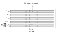
- FIG. 2 is a view showing a storage form of the disk cartridge 10 and a plurality of multilayer optical disks 11 therein.
- the accommodation form of the plurality of multilayer optical discs 11 in the disc cartridge 10 flat stacking, vertical alignment, and the like are assumed. In any case, it is preferable that a certain gap is provided between adjacent multilayer optical discs 11 so that the multilayer optical disc 11 can be smoothly inserted into and removed from the disc cartridge 10.
- the shape of the disk cartridge 10 is assumed to be, for example, a rectangular parallelepiped shape or a cylindrical shape from the viewpoint of handling by the user and the storage efficiency of the multilayer optical disk 11.
- a rectangular parallelepiped disk cartridge 10 in which a plurality of multilayer optical disks 11 are accommodated in a flat stack is used. *
- FIG. 3 is a diagram showing the configuration of the disk cartridge 10, the multilayer optical disk 11, and the drive unit 30.
- At least one side surface of the disc cartridge 10 is provided with an opening 110 for inserting and removing the multilayer optical disc 11 and a door (not shown) for opening and closing the opening 110.
- the door is opened and closed in conjunction with the operation of loading / unloading the multilayer optical disk 11 from / to the disk cartridge 10 by the disk transport mechanism 20, and is closed at other times.
- the plurality of multilayer optical disks 11 accommodated in the disk cartridge 10 are taken out by the disk transport mechanism 20 and selectively transported (loaded) to the plurality of disk drives 31 in the drive unit 30. *
- the configuration of the disk cartridge 10 is not limited to that shown in FIG.
- Various modifications such as the shape of the disk cartridge 10, the number and position of the openings, the presence / absence of a door, and the accommodation form of a plurality of multilayer optical disks 11 are possible.
- the multilayer optical disc 11 accommodated in the disc cartridge 10 is assumed to be a so-called guide layer separation type multilayer optical disc in which the guide layer and the recording layer are separated into separate layers. . *
- FIG. 4 is a cross-sectional view showing a configuration of a multilayer optical disc 11 that is a guide layer separation type multilayer optical disc.
- the multilayer optical disk 11 includes a guide layer 112 and a plurality of recording layers 113.
- the number of recording layers 113 is “4”.
- An intermediate layer 114 having optical transparency is interposed between the guide layer 112 and the recording layer 113 closest to the guide layer 112 and between the adjacent recording layers 113.
- These layers are the protective layer 115, the recording layer 113, the intermediate layer 114, the recording layer 113, the intermediate layer 114, the recording layer 113, the intermediate layer from the side on which the recording / reproducing light R1 and the guide light R2 from the optical pickup 32 are incident.
- the layer 114, the recording layer 113, the intermediate layer 114, and the guide layer 112 are stacked in this order.
- Each recording layer 113 is distinguished from the opposite side of the laser beam incident side (guide layer side) as “recording layer L0”, “recording layer L1”, “recording layer L2”, and “recording layer L3”. To do. *
- a guide track 121 having a land / groove structure is spirally or concentrically provided on the surface of the guide layer 112 facing the recording layer 113.
- physical address information is formed by wobbling or pit rows on the side wall surface.
- the guide track 121 is formed with a track pitch (for example, 0.64 ⁇ m) corresponding to red laser light used for recording / reproducing of a DVD (Digital Versatile Disk), for example.
- the average pitch between the land and the groove is, for example, 0.32 ⁇ m.
- the laser beam of the red laser beam is referred to as “guide light”. *
- a push-pull method (PP: Push-Pull)
- DPP Differential-Push-Pull
- 3 beams in each of the land and groove of the guide track 121 Tracking control is performed by law. By performing tracking control in each of the land and groove of the guide track 121, information can be recorded on the recording layer 113 at a track pitch of 0.32 ⁇ m.
- the recording layer 113 is a layer on which information is recorded at a track pitch (0.32 ⁇ m) corresponding to blue laser light used for recording / reproducing of a Blu-ray Disc (registered trademark), for example.
- this blue laser light is referred to as “recording / reproducing light” or “recording light”.
- the recording layer 113 is composed of, for example, a light absorption layer and a reflection layer.
- the light absorption layer organic dyes such as cyanine dyes and azo dyes, and inorganic materials such as Si, Cu, Sb, Te, and Ge are used.
- the target recording layer 113 in the multilayer optical disc 11 When the target recording layer 113 in the multilayer optical disc 11 is irradiated with the recording light, the reflectance of the area irradiated with the recording light is changed, and the area where the reflectance is changed is formed as a recording mark. Information is recorded in layer 113.
- the tracking control and the acquisition of the physical address and the reference clock at the time of recording information on the recording layer 113 are performed by using the guide track 121 of the guide layer 112. Therefore, the recording layer 113 has a land / groove structure guide track. 121 is not necessary. Therefore, the surface of the recording layer 113 may be flat.
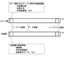
- FIG. 5 is a diagram showing a configuration of regions divided by radial positions of the guide layer 112 and the recording layer 113 in the multilayer optical disc 11.
- the guide layer 112 and the recording layer 113 are divided into the lead-in area, the data area, and the lead-out area in common from the inner circumference side depending on the position in the radial direction.
- management information unique to the multilayer optical disk 11 is recorded in advance by wobbling of guide tracks or pit rows provided in lands and grooves.
- the management information unique to the multilayer optical disc 11 includes, for example, recommended information such as the number of recording layers, recording method, recording linear velocity, laser power and laser drive pulse waveform during recording / reproduction, position information of the data area, position of the OPC area Contains information.
- the OPC area is provided, for example, on the inner peripheral side of the lead-in area.
- the position information (disk radius position) of each recording layer 113 is recorded in advance by wobbling of the guide track or pit rows provided in the land and groove. Has been. *
- the same information as the information recorded in the lead-in area may be recorded in advance by wobbling of the guide track 121 or a prepit row provided in the land and groove. Good. *
- the lead-in area of the recording layer 113 (hereinafter referred to as “recording layer lead-in area”) is an area where management information used for recording / reproduction of the recording layer 113 is recorded by a recording mark.
- Management information used for recording / reproduction of the recording layer 113 includes layer information such as a layer number assigned to which recording layer 113 is assigned, replacement management information regarding replacement processing of a defective area, OPC processing (calibration processing).
- the recording condition data such as the optimum laser power at the time of recording determined by (1) is included.
- at least the layer information is, for example, information recorded with a recording mark on each recording layer 113 before the multilayer optical disc 11 is actually used for data recording by the user.
- Such layer information may be recorded in advance on each recording layer when, for example, a multilayer optical disc is manufactured. If recording is performed when a multilayer optical disc is manufactured, layer information can be recorded for each manufacturing lot, so that layer information can be recorded more accurately without being subject to fluctuations in lot-to-lot variations.
- the disc conveying mechanism 20 takes out the target multilayer optical disk 11 from the disk cartridge 10 and loads it into the disk drive 31 in the drive unit 30, or conversely discharges the multilayer optical disk 11 ejected from the disk drive 31 into a disk This is a mechanism for returning to the cartridge 10.
- the disk transport mechanism 20 operates independently so that, for example, a plurality of multilayer optical disks 11 can be taken out simultaneously or sequentially from the disk cartridge 10 and can be separately loaded into the plurality of disk drives 31 in the drive unit 30.
- a plurality of possible transport mechanisms may be provided.
- a plurality of disk drives 31 are mounted in the drive unit 30. In the example of FIG. 5, five disk drives 31 are mounted. In the example of FIG. 5, five disk drives 31 are mounted. The number of multilayer optical disks 11 accommodated in the disk cartridge 10 and the number of disk drives 31 mounted in the drive unit 30 are not necessarily the same. *
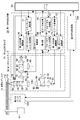
- FIGS. 6 and 7 are diagrams showing the configuration of the disk drive 31 that is an optical recording apparatus.
- the disk drive 31 includes a first optical pickup 32 and a second optical pickup 32a.
- the first optical pickup 32 includes a recording / reproducing optical system corresponding to the recording / reproducing light and a guide optical system corresponding to the guide light.
- the second optical pickup 32a includes a reproducing optical system.
- the disk drive 31 includes a first PU corresponding circuit group 22 corresponding to the first optical pickup 32, a second PU corresponding circuit group 22a corresponding to the second optical pickup 32a, and a controller 83.
- the disk drive 31 includes a disk motor 91 that drives the multilayer optical disk 11. *
- the disk drive 31 includes a disk motor drive unit that controls the disk motor 91, a first feed mechanism that sends the first optical pickup 32 in the radial direction of the multilayer optical disk 11, and a second optical pickup 32a that is a multilayer optical disk. 11 includes a second feed mechanism for feeding in the radial direction.
- a disk motor drive unit that controls the disk motor 91
- a first feed mechanism that sends the first optical pickup 32 in the radial direction of the multilayer optical disk 11
- a second optical pickup 32a that is a multilayer optical disk.
- 11 includes a second feed mechanism for feeding in the radial direction.
- the controller 83 includes a CPU (Central Processing Unit), ROM (Read Only Memory), RAM (Random Access Memory), and the like.
- the controller 83 controls the entire disk drive 31 based on a program loaded in the main memory area allocated to the RAM. *
- the recording / reproducing optical system of the first optical pickup 32 includes a first light source 33, a first collimator lens 34, a first polarization beam splitter 35, a first relay lens 36, and a second relay lens 36.
- the combining prism 38, the quarter wavelength plate 39, and the objective lens 60 belong to both the recording / reproducing optical system and a guide optical system described later.
- the first light source 33 includes a laser diode that emits blue laser light as recording / reproducing light R1.
- the recording / reproducing light R 1 emitted from the first light source 33 is converted into parallel light by the first collimator lens 34 and passes through the first polarization beam splitter 35, the first relay lens 36 and the second collimator lens 37.
- the light enters the combining prism 38.
- the combining prism 38 makes the optical axes of the recording / reproducing light R1 incident from the second collimator lens 37 and the guide light R2 incident from a third collimator lens belonging to a guide optical system, which will be described later, coincide with each other.
- And is incident on the objective lens 60 through the quarter-wave plate 39.
- the incident recording / reproducing light is collected by the objective lens 60 so as to be focused on the target recording layer 113 of the multilayer optical disc 11.
- the recording / reproducing light (returned light) reflected by the recording layer 113 is incident on the combining prism 38 via the objective lens 60 and the quarter wavelength plate 39, and is transmitted through the combining prism 38 in the incident direction.
- the first polarization beam splitter 35 reflects the return light of the first wavelength from the first relay lens 36 at an angle of about 90 degrees and passes through the first light receiving lens 61 to the first light receiving unit 62. Make it incident.
- the first light receiving unit 62 includes a light receiving element whose light receiving surface is divided into four in the disk radial direction and the tangential direction, and outputs a voltage signal of a level corresponding to the light receiving intensity for each divided light receiving surface. To do. *
- the guide optical system includes a second light source 63, a third collimator lens 64, a second polarizing beam splitter 65, a second relay lens 66, a fourth collimator lens 67, a combining prism 38, and a quarter wavelength plate 39.
- the second light source 63 emits guide light R2 that is red laser light.
- the guide light R2 emitted from the second light source 63 is converted into parallel light by the third collimator lens 64, and is combined through the second polarization beam splitter 65, the second relay lens 66, and the fourth collimator lens 67.
- the light enters the prism 38.
- the guide light R2 incident on the combining prism 38 is combined by the combining prism 38 so that the optical axis coincides with the recording / reproducing light R1 incident from the second collimator lens 37 of the recording / reproducing optical system.
- the light enters the objective lens 60 through the quarter-wave plate 39.
- the incident guide light R ⁇ b> 2 is collected by the objective lens 60 so as to be focused on the guide layer 112 of the multilayer optical disk 11. *
- the guide light R2 (return light) reflected by the guide layer 112 enters the synthesis prism 38 through the objective lens 60 and the quarter wavelength plate 39, and is reflected by the synthesis prism 38 at an angle of about 90 degrees.
- the second polarization beam splitter 65 reflects the return light of the guide light R2 from the second relay lens 66 at an angle of about 90 degrees, and passes through the second light receiving lens 68 to the second light receiving unit 69. Make it incident. *
- the second light receiving unit 69 is constituted by, for example, a light receiving element whose light receiving surface is divided into four in the disk radial direction and the tangential direction.
- the second light receiving unit 69 outputs a voltage signal corresponding to the amount of received light for each divided light receiving surface.
- the first optical pickup 32 is provided with a tracking actuator 70 and a focus actuator 79.
- the tracking actuator 70 moves the objective lens 60 in the disk radial direction that is perpendicular to the optical axis under the control of the tracking control unit 71.
- the focus actuator 79 moves the objective lens 60 in the optical axis direction under the control of the focus control unit 77.
- the first optical pickup 32 has a first relay lens actuator 80 for moving the first relay lens 36 in the optical axis direction and a guide light in order to switch the recording layer 113 irradiated with the recording / reproducing light.
- a second relay lens actuator 81 that moves the second relay lens 66 in the optical axis direction is provided.
- the first PU corresponding circuit group 22 includes a tracking error generation unit 82, a tracking control unit 71, a data modulation unit 72, a first light source driving unit 73, a second light source driving unit 74, and the like. , A data reproduction unit 76, a focus control unit 77, a first relay control unit 84, a second relay control unit 85, and a focus error generation unit 86. *
- the data modulator 72 modulates the recording data supplied from the controller 83 and supplies the modulated signal to the first light source driver 73.
- the first light source drive unit 73 generates a drive pulse for driving the first light source 33 based on the modulation signal from the data modulation unit 72.
- the equalizer 75 performs an equalization process such as PRML (Partial Response Maximum Likelihood) on the reproduction RF signal from the first light receiving unit 62 to generate a binary signal.
- PRML Partial Response Maximum Likelihood
- the data reproduction unit 76 demodulates data from the binary signal output from the equalizer 75, performs decoding processing such as error correction from the demodulated data, generates reproduction data, and supplies the reproduction data to the controller 83.
- the tracking error generation unit 82 generates a tracking error signal based on the output of the second light receiving unit 69 by, for example, a push-pull method, a differential push-pull method, a three-beam method, or the like.
- the tracking controller 71 performs tracking control by controlling the tracking actuator 70 based on the tracking error signal to move the objective lens 60 in a direction perpendicular to the optical axis.
- the tracking error generation unit 82 and the tracking control unit 71 correspond to a “first tracking processing unit” in the claims. *
- the focus error generation unit 86 generates a focus error signal based on, for example, the astigmatism method based on the output of the first light receiving unit 62.
- the focus control unit 77 performs focus control by controlling the focus actuator 79 and moving the objective lens 60 in the optical axis direction based on the focus error signal.
- the first relay control unit 84 controls the first relay lens actuator 80 so as to switch the recording layer to be recorded and reproduced.
- the second relay control unit 85 controls the second relay lens actuator 81 so that the guide light R2 is focused on the guide layer 112.
- the above is the description of the first PU-compatible circuit group 22. *
- the reproduction optical system of the second optical pickup 32a includes a third light source 33a, a fifth collimator lens 34a, a third polarization beam splitter 35a, a third relay lens 36a, and a sixth relay lens 36a. It is composed of a collimator lens 37a, a quarter wavelength plate 39a, an objective lens 60a, a third light receiving lens 61a, a third light receiving portion 62a, and the like.
- the third light source 33a includes a laser diode that emits blue laser light as reproduction light R3.
- the reproduction light R3 emitted from the third light source 33a is converted into parallel light by the fifth collimator lens 34a, and the third polarization beam splitter 35a, the third relay lens 36a, and the sixth collimator lens 37a, 1/4.
- the light enters the objective lens 60a through the wave plate 39a.
- the incident reproduction light R3 is condensed so as to be focused on the target recording layer 113 of the multilayer optical disc 11. *
- the reproduction light (return light) reflected by the recording layer 113 is transmitted to the third polarization beam splitter 35a via the objective lens 60a, the quarter wavelength plate 39a, the sixth collimator lens 37a, and the third relay lens 36a.
- the third polarization beam splitter 35a reflects the return light of the first wavelength from the third relay lens 36a at an angle of about 90 degrees, and passes through the third light receiving lens 61a to the third light receiving unit 62a. Make it incident.
- the third light receiving unit 62a is composed of, for example, a light receiving element whose light receiving surface is divided into four in the disk radial direction and the tangential direction, and outputs a voltage signal of a level corresponding to the light receiving intensity for each divided light receiving surface. To do. *
- the second optical pickup 32a is provided with a tracking actuator 70a and a focus actuator 79a.
- the tracking actuator 70a moves the objective lens 60a in the disk radial direction that is perpendicular to the optical axis under the control of the tracking control unit 71a.
- the focus actuator 79a moves the objective lens 60a in the optical axis direction under the control of the focus control unit 77a.
- the second optical pickup 32a is provided with a third relay lens actuator 80a for moving the third relay lens 36a in the optical axis direction in order to switch the recording layer 113 irradiated with the recording / reproducing light.
- the second PU corresponding circuit group 22a includes a tracking error generation unit 82a, a tracking control unit 71a, a third light source driving unit 73a, an equalizer 75a, a data reproduction unit 76a, a focus error generation unit 86a, a focus control unit 77a, A characteristic detector 78a and a third relay controller 84a are provided. *
- the third light source drive unit 73a generates a drive current for emitting the reproduction light R3 from the third light source 33a, and supplies the drive current to the third light source 33a.
- the equalizer 75a performs an equalization process such as PRML (Partial Response Maximum Likelihood) on the reproduction RF signal from the third light receiving unit 62a to generate a binary signal.
- PRML Partial Response Maximum Likelihood
- the data reproducing unit 76 a demodulates data from the binary signal output from the equalizer 75 a, performs decoding processing such as error correction from the demodulated data, generates reproduced data, and supplies the reproduced data to the controller 83.
- the tracking error generation unit 82a generates a tracking error signal by the push-pull method, the differential push-pull method, the 3-beam method, or the like based on the output of the third light receiving unit 62a.
- the tracking control unit 71a performs tracking control by controlling the tracking actuator 70a based on the tracking error signal and moving the objective lens 60a in a direction perpendicular to the optical axis.
- the tracking error generator 82a and the tracking controller 71a correspond to a “second tracking processor” in the claims. *
- the focus error generation unit 86a generates a focus error signal by, for example, the astigmatism method based on the output of the third light receiving unit 62a.
- the focus control unit 77a performs focus control by controlling the focus actuator 79a and moving the objective lens 60a in the optical axis direction based on the focus error signal.
- the third relay control unit 84a controls the third relay lens actuator 80a so as to switch the recording layer to be reproduced.
- the characteristic detection unit 78a receives the voltage signal output from the third light receiving unit 62a, detects the physical characteristic value of the reproduction light (return light) based on this voltage signal, and supplies it to the controller 83.
- a plurality of the disk drives 31 described above are mounted on the drive unit 30 and can be controlled independently, and information can be recorded and reproduced on the loaded multilayer optical disk 11 simultaneously.
- RAID Controller 40 A RAID (Redundant Arrays of Inexpensive Disks) controller 40 records data in multiple on one or more disk drives 31 in the drive unit 30 in response to a recording command from the host device 50, or performs striping. RAID control to record in a distributed manner is performed.
- the controller 83 of each disk drive 31 to which a recording or reproduction instruction is given from the RAID controller 40 performs control for recording or reproducing data on the multilayer optical disk 11.
- the host device 50 is the highest-level device that controls the optical recording system 1.
- the host device 50 may be a personal computer.
- the host device 50 creates or prepares data for recording, and supplies a recording command for the data for recording to the RAID controller 40. Further, the host device 50 supplies a read command including a file name designated by a user or the like to the RAID controller 40, and acquires data of the corresponding file name from the RAID controller 40 as a response.
- the host device 50 includes a CPU 51, a memory 52, a drive I / F 53, a disk transport mechanism I / F 54, and a system bus 56. *
- the CPU 51 performs arithmetic processing for executing a program stored in the memory 52 and controls exchange of information with each unit through the system bus 56.
- the memory 52 is a main memory in which programs to be executed by the CPU 51 and calculation results are stored.
- the drive I / F 53 is an interface for communicating with the plurality of disk drives 31 through the RAID controller 40. *
- the disk transport mechanism I / F 54 is an interface for communicating with the disk transport mechanism 20. *
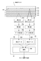
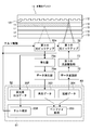
- FIG. 8 is a diagram for explaining a verification mechanism in the disk drive 31 according to the present embodiment.
- the disk drive 31 has a first optical pickup 32 and a second optical pickup 32a.
- the first optical pickup 32 and the second optical pickup 32a may be independent so that they can be moved individually in the disk radial direction, or can be moved simultaneously. It may be integrated. 6, 7, and 8, it is assumed that the first optical pickup 32 and the second optical pickup 32 a are independent from each other.
- the controller 83 can move the first optical pickup 32 and the second optical pickup 32a in the disk radial direction by controlling the corresponding feed mechanisms (not shown). *
- the second optical pickup 32a is spirally formed on the guide layer 112, for example, with respect to the recording position so that the recorded data can be reproduced during recording of the data by the first optical pickup 32. It is positioned on the downstream side in the recording direction X along the provided guide track 121.
- the downstream side in the recording direction X along the guide track 121 is defined as follows. Downstream side of the disk orbit 2. 2. Downstream side in the disk radial direction The meaning of the downstream side between the recording layers of a multilayer optical disk is included. *
- a data recording command is given from the host device 50 to the controller 83 of one or more disk drives 31 in the drive unit 30 through the RAID controller 40. Since the operation of each disk drive 31 when receiving a recording command is the same, the operation of one disk drive 31 will be described.
- the controller 83 of the disk drive 31 controls the first feed mechanism so as to move the first optical pickup 32 to the disk radial position corresponding to the unrecorded area in the multilayer optical disk 11, and controls a disk motor drive unit (not shown).
- the multi-layer optical disk 11 is driven to rotate at an appropriate speed by control.
- the controller 83 controls the first relay lens of the first optical pickup 32 so that the recording light from the objective lens 60 of the first optical pickup 32 is focused on the target recording layer 113 (L0) of the multilayer optical disc 11.
- a control command is supplied to the focus control unit 77 so as to control the position of the optical axis direction 36 and start pulling in the focus servo.
- the controller 83 also has an optical axis of the second relay lens 66 of the first optical pickup 32 so that the guide light from the objective lens 60 of the first optical pickup 32 is focused on the guide layer 112 of the multilayer optical disc 11.
- a control command is supplied to the tracking control unit 71 so as to control the position in the direction and start the tracking servo pull-in.
- the controller 83 of the disk drive 31 stores the recording data 201 transferred from the host device 50 through the RAID controller 40 in the memory 52 and transfers the recording data 201 from the memory 52 to the data modulation unit 72.
- the data modulator 72 generates a recording signal by modulating the recording data 201 and adding an error correction code, and supplies the recording signal to the first light source driving unit 73.
- the first light source driving unit 73 generates a driving pulse for the first light source 33 based on the recording signal and supplies it to the first light source 33.
- the controller 83 moves the second optical pickup 32a in the multilayer optical disc 11.
- the second feed mechanism is controlled to move to the disk radial position where the current recording is started.
- the controller 83 causes the third relay lens of the second optical pickup 32a to focus the reproduction light from the objective lens 60a of the second optical pickup 32a on the target recording layer 113 (L0) of the multilayer optical disc 11.
- a control command is supplied to the focus control unit 77 so as to control the position of the optical axis direction 36a and start pulling in the focus servo.
- the controller 83 supplies a control command to the tracking control unit 71a so as to start the tracking servo pull-in by DPD with respect to the recording mark of the target recording layer 113 (L0) of the multilayer optical disc 11.
- the controller 83 supplies a control command to the third light source driving unit 73a so that the reproduction light is emitted from the third light source 33a. Thereby, the reproduction of the data recorded by the first optical pickup 32 is started.
- the data 202 reproduced by the data reproducing unit 76 a is supplied to the controller 83 and stored in the memory 52.
- the CPU 51 of the controller 83 executes the verify 203 by collating the reproduction data 202 stored in the memory 52 with the recording data 201, for example.
- the verify 203 is executed each time reproduction data 202 in a unit that can be verified is obtained from the multilayer optical disc 11.
- the CPU 51 records the data unit in which the error is detected in another area by a replacement process.
- the CPU 51 of the controller 83 performs OPC based on a signal read from the recorded area by the second optical pickup 32a even during data recording using the first optical pickup 32.
- (Optimized Power Control) 204 can be executed.
- the characteristic detection unit 78a receives the voltage signal output from the third light receiving unit 62a, detects the physical characteristic value of the return light based on this voltage signal, and supplies the characteristic value data 209 to the controller 83.
- the physical characteristic value of the return light for example, an asymmetry value which is an evaluation index indicating the symmetry of amplitude between the shortest recording mark and the shortest space and the longest recording mark and the longest space in the reproduction RF signal, and similarly the symmetry of the RF signal
- the present invention is not limited to these values. *
- the CPU 51 of the controller 83 corrects the intensity level (power level) of the recording laser beam emitted from the first light source 33 of the first optical pickup 32 based on the characteristic value detected by the characteristic detector 78a.
- the predetermined OPC 204 is executed, for example, by supplying a control signal for correction to the first light source driving unit 73.
- the disk drive 31 of this embodiment can reproduce the recorded data by the second optical pickup 32a during recording by the first optical pickup 32.
- the recording data can be verified in parallel with the data recording on the multilayer optical disk 11.
- the time from the start of recording to the end of verification can be greatly shortened.
- a remarkable speed increase is achieved.
- the track mark is performed on the recording mark of the recording layer.
- tracking error due to tilt can be reduced, so that tracking can be performed with high accuracy and the frequency of retries during playback can be suppressed.
- FIG. 9 is a diagram for explaining Modification 1 of the present embodiment.
- the controller 83 may control the first optical pickup 32 and the second optical pickup 32a to be used for reproduction. That is, the controller 83 controls the first optical pickup 32 and the second optical pickup 32a to simultaneously read data at different addresses on the multilayer optical disc 11, and combines the two reproduction data 205 and 202 in the memory 52 ( 206) and transfer to the host device 50. Thereby, the transfer rate at the time of reproduction
- FIG. 10 is a diagram for explaining Modification 2 of the present embodiment.
- the controller 83 can correct the tilt caused by the warp of the multilayer optical disc 11 in real time using the output of the third light receiving unit 62a of the second optical pickup 32a. It is.
- the first optical pickup 32 and the second optical pickup 32a are provided with tilt actuators and the like for adjusting the inclinations of the objective lenses 60 and 60a in the radial direction and the tangential direction, respectively.
- the CPU 51 of the controller 83 detects the tilt amount using the output data 207 of the third light receiving unit 62a, generates a correction value so that the tilt amount becomes zero, and outputs a control signal to the tilt actuator.
- the tilt correction 208 of the first optical pickup 32 and the second optical pickup 32a can be performed.
- the modulation degree of the amplitude voltage of the reproduction RF signal is expressed by (RFtop ⁇ RFbottom) / RFtop, where the peak voltage of the reproduction RF signal is RFtop and the bottom value is RFbottom.
- the controller 83 performs tilt correction so that the modulation degree of the amplitude voltage of the reproduction RF signal is maximized.
- tilt correction based on the modulation degree of the amplitude voltage of the reproduction RF signal is merely an example, and other known methods may be used to perform the tilt correction.
- the present invention is not limited to the above-described embodiment, and various modifications can be made without departing from the gist of the present invention.
- only one disk drive 31 may be used, and in this case, a cartridge and a disk transport mechanism are not required, and thus the size can be reduced.
Landscapes
- Optical Recording Or Reproduction (AREA)
- Physics & Mathematics (AREA)
- Optics & Photonics (AREA)
- Optical Head (AREA)
Description
本発明は、光ディスクに対して記録を行うことが可能な光記録装置および光記録方法に関する。
DVD(Digital Versatile Disk)、ブルーレイディスク(登録商標)などの光ディスクの大容量化を目的として、記録層を多層化することが行われる。記録層の多層化に伴い、記録層へのデータの記録または再生時のトラックキング制御を、記録層とは別の層に設けられたガイドトラックを用いて行う方式も知られている。例えば、溝構造によるガイドトラックが設けられたガイドトラック層に650nm~680nmの波長(赤色)の光(ガイド光)を使用してトラッキング制御を行うとともに、複数の記録層のうちの一つの記録層に390nm~420nmの波長(青色)の光(記録再生光)を使用して記録を行う光ディスクドライブなどがある。
また、光ディスクへの記録が可能な光ディスクドライブでは、記録データの信頼性確保のために、光ピックアップで光ディスクにデータを記録した後、記録されたデータを再生し、記録元のデータと再生データとを照合するなどして、正しくデータを記録できたかどうかを検証するベリファイ動作が行われる(特許文献1参照)。
通常、ベリファイ動作においては、光ディスクへのデータの記録が完了した後、データが記録された先頭トラックに対応する位置まで光ピックアップを戻してからデータを読み込んで再生する必要がある。したがって、結果的に光ピックアップはディスク上の今回の記録位置を最低2回トレースすることになり、この点が全体的な記録時間の短縮を阻む要因の一つとなっていた。この問題は、多層光ディスクのようにメディアの記録容量の増大に連れて顕著となる。
以上のような事情に鑑み、本発明の目的は、ベリファイ動作を含めた記録を高速化することのできる光記録装置及び光記録方法を提供することにある。
上記目的を達成するため、本発明の一形態に係る光記録装置は、情報を記録可能な1以上の記録層と、トラッキングのためのガイドトラックが設けられたガイド層とを有する光ディスクに記録を行う光記録装置であって、前記光ディスクの前記記録層にデータを記録することが可能な第1の光ピックアップと、前記光ディスクから前記記録されたデータを読み出すことが可能な第2の光ピックアップと、前記第1の光ピックアップを用いた前記データの記録中、前記記録されたデータを前記第2の光ピックアップを用いて読み出し、ベリファイを行うように制御を行う制御部と、を具備する。
本発明に係る光記録装置では、互いに独立して動作可能な第1の光ピックアップと第2の光ピックアップを有し、制御部が、第1の光ピックアップを用いたデータの記録中、記録されたデータを第2の光ピックアップを用いて読み出し、ベリファイを行うように制御を行う。すなわち、本発明によれば、多層光ディスクの記録層への記録とその記録データのベリファイとを同時に実行する期間を生成することができ、ベリファイ動作を含めた記録を高速化することができる。
本発明に係る光記録装置において、前記第1の光ピックアップは、記録用のレーザ光を前記光ディスクの前記記録層に照射して記録を行うための記録光学系と、ガイド用のレーザ光を前記光ディスクの前記ガイド層に照射して戻り光に応じた第1の信号を出力するガイド光学系とを含み、前記第2の光ピックアップは、再生用のレーザ光を前記光ディスクの前記記録層に照射して戻り光に応じた第2の信号を出力する第1の再生光学系を含み、前記光記録装置は、さらに、前記第1の光ピックアップの前記ガイド光学系より出力された前記第1の信号を用いて、前記第1の光ピックアップのトラッキングに関する処理を行う第1のトラッキング処理部と、前記第2の光ピックアップの前記第1の再生光学系より出力された前記第2の信号を用いて、前記第2の光ピックアップのトラッキングに関する処理を行う第2のトラッキング処理部とを具備するものであってよい。
多層光ディスクの記録層に記録されたデータを第2の光ピックアップで再生する場合には、記録層の記録マークに対してトラックキングが行われることで、ガイド層のガイドトラックに対してトラッキングを行う場合に比較して、例えばチルトによるトラッキングの誤差などが低減される分、精度良くトラッキングを行うことができ、再生時のリードリトライの頻度を抑えられる。これにより、記録開始からベリファイ終了までの時間をより短縮することができる。
本発明に係る光記録装置は、前記第2の光ピックアップの前記再生光学系より出力された前記第2の信号をもとに、前記戻り光の物理特性値を検出する特性検出部をさらに具備し、前記制御部は、前記検出された物理特性値をもとにOPC(Optimized Power Control)を行うものであってよい。
本発明に係る光記録装置において、前記第1の光ピックアップは、再生用のレーザ光を前記光ディスクの前記記録層に照射して戻り光に応じた第3の信号を出力する第2の再生光学系を含み、前記制御部は、前記第1の光ピックアップの前記第2の再生光学系および前記第2の光ピックアップの前記第1の再生光学系を同時に用いて再生を行うように制御するものであってよい。 これにより、再生時の転送レートを大幅に引き上げることができる。
本発明に係る光記録装置において、前記制御部は、前記第2の光ピックアップの第1の再生光学系より出力された前記第2の信号をもとに、前記第1の光ピックアップ及び前第2の光ピックアップのチルト補正を行うものであってよい。
本発明の別の観点に基づく光記録方法は、情報を記録可能な1以上の記録層と、トラッキングのためのガイドトラックが設けられたガイド層とを有する多層光ディスクに記録を行う方法であって、第1の光ピックアップにより前記光ディスクの前記記録層にデータの記録を行い、この記録中に前記記録されたデータを、前記第1の光ピックアップに対して独立して動作可能な光ピックアップにより再生し、ベリファイを行う、というものである。
以上のように、本発明によれば、ベリファイ動作を含めた記録を高速化することができる。
以下、図面を参照しながら、本発明の実施形態を説明する。
<第1の実施形態>
図1は、本発明の第1の実施形態に係る光記録システムを示す図である。
<第1の実施形態>
図1は、本発明の第1の実施形態に係る光記録システムを示す図である。
図1は光記録システムの全体の構成を示す図である。 この光記録システム1は、ディスクカートリッジ10と、ディスク搬送機構20と、ドライブユニット30と、RAIDコントローラ40と、ホスト装置50とを備える。以下、それぞれの詳細について説明する。
[ディスクカートリッジ10] ディスクカートリッジ10は、複数の多層光記録媒体である多層光ディスク11が個別に着脱自在に収容されるユニットである。
図2はディスクカートリッジ10とこの中の複数の多層光ディスク11の収容形態を示す図である。ディスクカートリッジ10内での複数の多層光ディスク11の収容形態としては平積み、縦並びなどが想定される。いずれの場合も、ディスクカートリッジ10に対して多層光ディスク11の出し入れが円滑に行われるように、隣り合う多層光ディスク11間には一定の隙間が設けられることが好ましい。ディスクカートリッジ10の形状は、ユーザによるハンドリング性、多層光ディスク11の収納効率などの点から、例えば直方体形状、円筒形状などが想定される。図2の例では、複数の多層光ディスク11を平積みで収容した直方体形状のディスクカートリッジ10が用いられる。
図3は、ディスクカートリッジ10、多層光ディスク11およびドライブユニット30の構成を示す図である。 ディスクカートリッジ10の少なくとも一つの側面には多層光ディスク11の出し入れのための開口部110と、この開口部110を開閉する扉(図示せず)とが設けられている。扉はディスク搬送機構20によるディスクカートリッジ10からの多層光ディスク11の出し入れの動作と連動して開閉され、その他のときは閉状態とされる。ディスクカートリッジ10に収容された複数の多層光ディスク11は、ディスク搬送機構20によって取り出され、ドライブユニット30内の複数のディスクドライブ31に選択的に搬送(装填)される。
なお、本発明において、ディスクカートリッジ10の構成は図2のものに限定されない。ディスクカートリッジ10の形状、開口部の数や位置、扉の有無、複数の多層光ディスク11の収容形態など、様々な変形が可能である。
[多層光ディスク11] ディスクカートリッジ10に収容される多層光ディスク11は、ガイド層と記録層とが別々の層に分離して形成された、いわゆるガイド層分離型多層光ディスクである場合を想定している。
図4はガイド層分離型多層光ディスクである多層光ディスク11の構成を示す断面図である。 多層光ディスク11は、ガイド層112と複数の記録層113とを有する。同図の多層光ディスク11の例では記録層113の層数は"4"である。ガイド層112とこれに最も近い記録層113との間、隣り合う記録層113の間との間には光透過性を有する中間層114がそれぞれ介層されている。これらの層は、光ピックアップ32からの記録再生光R1およびガイド光R2が入射される側から、保護層115、記録層113、中間層114、記録層113、中間層114、記録層113、中間層114、記録層113、中間層114、ガイド層112の順に積層配置される。 なお、それぞれの記録層113をレーザ光入射側の反対側(ガイド層側)よりそれぞれ「記録層L0」、「記録層L1」、「記録層L2」、「記録層L3」と表記して区別する。
ガイド層112において記録層113に対向する側の面には、ランド・グルーブ構造によるガイドトラック121が螺旋状あるいは同心円状に設けられている。ガイドトラック121には、側壁面のウォブリングあるいはピット列などによって物理アドレス情報が形成されている。ガイドトラック121は、例えばDVD(Digital Versatile Disk)の記録再生に用いられる赤色レーザ光に対応するトラックピッチ(例えば0.64μm)で形成される。ランドとグルーブ間のピッチの平均は例えば0.32μmである。以後、赤色レーザ光のレーザ光を「ガイド光」と呼ぶ。
本実施形態の光記録システム1では、ガイドトラック121のランドとグルーブのそれぞれにおいて、例えば、プッシュプル法(PP:Push-Pull)、差動プッシュプル法(DPP:Differential Push-Pull)、3ビーム法などによるトラッキング制御が行われる。ガイドトラック121のランドとグルーブのそれぞれにおいてトラッキング制御が行われることで、記録層113に対する情報の記録は0.32μmのトラックピッチで行うことが可能である。
記録層113は、例えばブルーレイディスク(登録商標)の記録再生に用いられる青色レーザ光に対応するトラックピッチ(0.32μm)で情報の記録が行われる層である。以後、この青色レーザ光を「記録再生光」または「記録光」と呼ぶ。記録層113は、例えば光吸収層と反射層等とにより構成される。光吸収層としてはシアニン系色素やアゾ系色素等の有機色素や、Si、Cu、Sb、Te、Ge等の無機材料が用いられる。記録光が多層光ディスク11における目的の記録層113に照射されると、その記録光が照射された領域の反射率が変化し、反射率が変化した領域が記録マークとして形成されることで、記録層113に情報が記録される。
なお、記録層113への情報の記録時のトラッキング制御および物理アドレスならびに基準クロックの取得は、ガイド層112のガイドトラック121を用いて行われるため、記録層113にはランド・グルーブ構造によるガイドトラック121は不要である。したがって、記録層113の表面は平坦でよい。
図5は多層光ディスク11におけるガイド層112および記録層113の半径方向の位置によって区分される領域の構成を示す図である。 ガイド層112および記録層113は、半径方向における位置によって内周側よりリードイン領域、データ領域、リードアウト領域に各層共通に区分される。
ガイド層112のリードイン領域には、多層光ディスク11に固有の管理情報がガイドトラックのウォブリング、あるいはランドとグルーブに設けられたピット列などによって予め記録されている。 多層光ディスク11に固有の管理情報は、例えば、記録層の数、記録方式、記録線速度、記録再生時のレーザパワーおよびレーザ駆動パルス波形などの推奨情報、データ領域の位置情報、OPC領域の位置情報などを含む。OPC領域は例えばリードイン領域よりも内周側に設けられる。 また、ガイド層112のリードイン領域には、それぞれの記録層113のリードイン領域の位置情報(ディスク半径位置)が、ガイドトラックのウォブリング、あるいはランドとグルーブに設けられたピット列などによって予め記録されている。
ガイド層112のデータ領域には、当該データ領域に対して割り当てられた物理アドレス情報が、ガイドトラック121のウォブリング、あるいはランドとグルーブに設けられたプリピット列などによって予め記録されている。
なお、ガイド層112のリードアウト領域にも、リードイン領域に記録された情報と同一の情報が、ガイドトラック121のウォブリング、あるいはランドとグルーブに設けられたプリピット列などによって予め記録されていてもよい。
記録層113のリードイン領域(以下「記録層リードイン領域」と呼ぶ)は、記録層113の記録再生に用いられる管理情報が記録マークによって記録される領域である。記録層113の記録再生に用いられる管理情報は、当該記録層113が何層目であるかを割り当てられた層番号などの層情報、欠陥領域の交替処理に関する交替管理情報、OPC処理(校正処理)によって決定された記録時の最適なレーザパワーなどの記録条件データなどを含む。この中で、少なくとも層情報は、例えば、当該多層光ディスク11がユーザによるデータの記録に実際に利用される以前に各記録層113に記録マークで記録された情報である。このような層情報は、例えば多層光ディスクを製造する際に各記録層に予め記録しておいてもよい。多層光ディスクを製造する際に記録を行えば、製造ロットごとに層情報を記録することができるのでロット間ばらつきの変動を受けることなく、より正確に層情報を記録することが可能である。
[ディスク搬送機構20] ディスク搬送機構20は、ディスクカートリッジ10から目的の多層光ディスク11を取り出してドライブユニット30内のディスクドライブ31に装填したり、逆にディスクドライブ31から排出された多層光ディスク11をディスクカートリッジ10に戻したりするための機構である。
ディスク搬送機構20は、例えば、ディスクカートリッジ10から同時あるいは順番連続して複数の多層光ディスク11を取り出し、ドライブユニット30内の複数のディスクドライブ31に別々に装填することができるように、独立して動作可能な複数の搬送機構を備えたものであってもよい。
[ドライブユニット30] ドライブユニット30には複数のディスクドライブ31が搭載される。同図の例では、5機のディスクドライブ31が搭載される。同図の例では、5機のディスクドライブ31が搭載される。ディスクカートリッジ10に収容される多層光ディスク11の数とドライブユニット30内に搭載されるディスクドライブ31の数は必ずしも同じとする必要はない。
(ディスクドライブ31の構成) 図6および図7は光記録装置であるディスクドライブ31の構成を示す図である。 このディスクドライブ31は、第1の光ピックアップ32と第2の光ピックアップ32aを備える。第1の光ピックアップ32は、記録再生光に対応する記録再生光学系と、ガイド光に対応するガイド光学系とを備える。第2の光ピックアップ32aは再生光学系を備える。
このディスクドライブ31は、第1の光ピックアップ32に対応する第1のPU対応回路群22と、第2の光ピックアップ32aに対応する第2のPU対応回路群22aと、コントローラ83とを備える。また、ディスクドライブ31は、多層光ディスク11を駆動するディスクモータ91を備える。
さらに、ディスクドライブ31は、ディスクモータ91を制御するディスクモータ駆動部と、第1の光ピックアップ32を多層光ディスク11の半径方向に送る第1のフィード機構と、第2の光ピックアップ32aを多層光ディスク11の半径方向に送る第2のフィード機構などを備える。図6および図7において、これらの図示は省略する。
コントローラ83は、CPU(Central Processing Unit)、ROM(Read Only Memory)、RAM(Random Access Memory)などを備える。コントローラ83は、RAMに割り当てられたメインメモリの領域にロードされたプログラムに基づいて、ディスクドライブ31の全体の制御を行う。
図6に示すように、第1の光ピックアップ32の記録再生光学系は、第1の光源33、第1のコリメータレンズ34、第1の偏光ビームスプリッタ35、第1のリレーレンズ36、第2のコリメータレンズ37、合成プリズム38、1/4波長板39、対物レンズ60、第1の受光レンズ61および第1の受光部62などで構成される。ここで、合成プリズム38、1/4波長板39、対物レンズ60は、当該記録再生光学系と後述するガイド光学系の両方に属する。
第1の光源33は青色レーザ光を記録再生光R1として出射するレーザダイオードを備える。第1の光源33から出射された記録再生光R1は第1のコリメータレンズ34によって平行光とされ、第1の偏光ビームスプリッタ35、第1のリレーレンズ36及び第2のコリメータレンズ37を介して合成プリズム38に入射する。合成プリズム38は、第2のコリメータレンズ37から入射される記録再生光R1と、後述するガイド光学系に属する第3のコリメータレンズから入射されるガイド光R2とを互いの光軸が一致するように合成し、1/4波長板39を介し
て対物レンズ60に入射させる。対物レンズ60にて、入射された記録再生光は、多層光ディスク11の目的の記録層113に合焦させるように集光される。
て対物レンズ60に入射させる。対物レンズ60にて、入射された記録再生光は、多層光ディスク11の目的の記録層113に合焦させるように集光される。
記録層113によって反射された記録再生光(戻り光)は、対物レンズ60、1/4波長板39を介して合成プリズム38に入射し、合成プリズム38を入射方向のまま透過して、第2のコリメータレンズ37及び第1のリレーレンズ36を介して第1の偏光ビームスプリッタ35に戻る。第1の偏光ビームスプリッタ35は、第1のリレーレンズ36からの第1の波長の戻り光を約90度の角度で反射して第1の受光レンズ61を介して第1の受光部62に入射させる。
第1の受光部62は、例えば、受光面がディスク半径方向とタンジェンシャル方向に4分割された受光素子などで構成され、分割された受光面毎に受光強度に応じたレベルの電圧信号を出力する。
ガイド光学系は、第2の光源63、第3のコリメータレンズ64、第2の偏光ビームスプリッタ65、第2のリレーレンズ66、第4のコリメータレンズ67、合成プリズム38、1/4波長板39、対物レンズ60、第2の受光レンズ68および第2の受光部69などで構成される。
第2の光源63は、赤色レーザ光であるガイド光R2を出射する。第2の光源63から出射されたガイド光R2は第3のコリメータレンズ64によって平行光とされ、第2の偏光ビームスプリッタ65、第2のリレーレンズ66及び第4のコリメータレンズ67を介して合成プリズム38に入射する。合成プリズム38に入射されたガイド光R2は、前述したように、合成プリズム38にて記録再生光学系の第2のコリメータレンズ37から入射される記録再生光R1と光軸が一致するように合成され、1/4波長板39を介して対物レンズ60に入射される。対物レンズ60にて、入射されたガイド光R2は、多層光ディスク11のガイド層112に合焦させるように集光される。
ガイド層112によって反射されたガイド光R2(戻り光)は、対物レンズ60、1/4波長板39を介して合成プリズム38に入射し、合成プリズム38にて約90度の角度で反射され、第4のコリメータレンズ67及び第2のリレーレンズ66を介して第2の偏光ビームスプリッタ65に戻る。第2の偏光ビームスプリッタ65は、第2のリレーレンズ66からのガイド光R2の戻り光を、約90度の角度で反射して第2の受光レンズ68を介して第2の受光部69に入射させる。
第2の受光部69は、例えば、受光面がディスク半径方向とタンジェンシャル方向に4分割された受光素子などで構成される。第2の受光部69は、分割された受光面毎に受光量に対応した電圧信号を出力する。
また、第1の光ピックアップ32には、トラッキングアクチュエータ70とフォーカスアクチュエータ79が設けられている。トラッキングアクチュエータ70はトラッキング制御部71による制御のもとで対物レンズ60を光軸に対して垂直な方向であるディスク半径方向に移動させる。フォーカスアクチュエータ79はフォーカス制御部77による制御のもと対物レンズ60を光軸方向に移動させる。
さらに、第1の光ピックアップ32には、記録再生光が照射される記録層113を切り替えるために、第1のリレーレンズ36を光軸方向に移動させる第1のリレーレンズアクチュエータ80と、ガイド光R2をガイド層112に合焦させるために、第2のリレーレンズ66を光軸方向に移動させる第2のリレーレンズアクチュエータ81が設けられている。
次に、第1のPU対応回路群22の構成を説明する。 図6に示すように、第1のPU対応回路群22は、トラッキングエラー生成部82、トラッキング制御部71、データ変調部72、第1の光源駆動部73、第2の光源駆動部74、等化器75、データ再生部76、フォーカス制御部77、第1のリレー制御部84、第2のリレー制御部85、およびフォーカスエラー生成部86を備える。
データ変調部72は、コントローラ83より供給された記録用のデータを変調し、変調信号を第1の光源駆動部73に供給する。
第1の光源駆動部73は、データ変調部72からの変調信号をもとに第1の光源33を駆動するための駆動パルスを生成する。
等化器75は、第1の受光部62からの再生RF信号に対して、例えばPRML(Partial Response Maximum Likelihood)などの等化処理を行って二値信号を生成する。
データ再生部76は、等化器75より出力された二値信号からデータを復調し、復調されたデータから誤り訂正などの復号処理を行って再生データを生成し、コントローラ83に供給する。
トラッキングエラー生成部82は、第2の受光部69の出力をもとに、例えばプッシュプル法、差動プッシュプル法、3ビーム法などによってトラッキングエラー信号を生成する。
トラッキング制御部71は、トラッキングエラー信号をもとにトラッキングアクチュエータ70を制御して対物レンズ60を光軸に対して垂直な方向に移動させることによってトラッキング制御を行う。トラッキングエラー生成部82およびトラッキング制御部71は特許請求の範囲の「第1のトラッキング処理部」に相当する。
フォーカスエラー生成部86は、第1の受光部62の出力をもとに、例えば、非点収差法などによりフォーカスエラー信号を生成する。
フォーカス制御部77は、フォーカスエラー信号をもとに、フォーカスアクチュエータ79を制御して対物レンズ60を光軸方向に移動させることによってフォーカス制御を行う。
第1のリレー制御部84は、記録再生対象の記録層を切り替えるように第1のリレーレンズアクチュエータ80を制御する。
第2のリレー制御部85は、ガイド光R2をガイド層112に合焦させるように第2のリレーレンズアクチュエータ81を制御する。 以上が、第1のPU対応回路群22の説明である。
次に、第2の光ピックアップ32aとこの第2の光ピックアップ32aに対応する第2のPU対応回路群22aの構成を説明する。 図7に示すように、第2の光ピックアップ32aの再生光学系は、第3の光源33a、第5のコリメータレンズ34a、第3の偏光ビームスプリッタ35a、第3のリレーレンズ36a、第6のコリメータレンズ37a、1/4波長板39a、対物レンズ60a、第3の受光レンズ61aおよび第3の受光部62aなどで構成される
第3の光源33aは青色レーザ光を再生光R3として出射するレーザダイオードを備える。第3の光源33aから出射された再生光R3は第5のコリメータレンズ34aによって平行光とされ、第3の偏光ビームスプリッタ35a、第3のリレーレンズ36a及び第6のコリメータレンズ37a、1/4波長板39aを介して対物レンズ60aに入射される。対物レンズ60aでは、入射された再生光R3は、多層光ディスク11の目的の記録層113に合焦させるように集光される。
記録層113によって反射された再生光(戻り光)は、対物レンズ60a、1/4波長板39a、第6のコリメータレンズ37a及び第3のリレーレンズ36aを介して第3の偏光ビームスプリッタ35aに戻る。第3の偏光ビームスプリッタ35aは、第3のリレーレンズ36aからの第1の波長の戻り光を約90度の角度で反射して第3の受光レンズ61aを介して第3の受光部62aに入射させる。
第3の受光部62aは、例えば、受光面がディスク半径方向とタンジェンシャル方向に4分割された受光素子などで構成され、分割された受光面毎に受光強度に応じたレベルの電圧信号を出力する。
また、第2の光ピックアップ32aには、トラッキングアクチュエータ70aとフォーカスアクチュエータ79aが設けられている。トラッキングアクチュエータ70aはトラッキング制御部71aによる制御のもとで対物レンズ60aを光軸に対して垂直な方向であるディスク半径方向に移動させる。フォーカスアクチュエータ79aはフォーカス制御部77aによる制御のもと対物レンズ60aを光軸方向に移動させる。
さらに、第2の光ピックアップ32aには、記録再生光が照射される記録層113を切り替えるために、第3のリレーレンズ36aを光軸方向に移動させる第3のリレーレンズアクチュエータ80aが設けられている。
次に、第2のPU対応回路群22aの構成を説明する。 第2のPU対応回路群22aは、トラッキングエラー生成部82a、トラッキング制御部71a、第3の光源駆動部73a、等化器75a、データ再生部76a、フォーカスエラー生成部86a、フォーカス制御部77a、特性検出部78aおよび第3のリレー制御部84aを備える。
第3の光源駆動部73aは、第3の光源33aより再生光R3を出射させるための駆動電流を生成し、第3の光源33aに供給する。
等化器75aは、第3の受光部62aからの再生RF信号に対して、例えばPRML(Partial Response Maximum Likelihood)などの等化処理を行って二値信号を生成する。
データ再生部76aは、等化器75aより出力された二値信号からデータを復調し、復調されたデータから誤り訂正などの復号処理を行って再生データを生成し、コントローラ83に供給する。
トラッキングエラー生成部82aは、第3の受光部62aの出力をもとに、例えばプッシュプル法、差動プッシュプル法、3ビーム法などによってトラッキングエラー信号を生成する。
トラッキング制御部71aは、トラッキングエラー信号をもとにトラッキングアクチュエータ70aを制御して対物レンズ60aを光軸に対して垂直な方向に移動させることによってトラッキング制御を行う。ここで、トラッキングエラー生成部82aおよびトラッキング制御部71aは特許請求の範囲の「第2のトラッキング処理部」に相当する。
フォーカスエラー生成部86aは、第3の受光部62aの出力をもとに、例えば、非点収差法などによりフォーカスエラー信号を生成する。
フォーカス制御部77aは、フォーカスエラー信号をもとに、フォーカスアクチュエータ79aを制御して対物レンズ60aを光軸方向に移動させることによってフォーカス制御を行う。
第3のリレー制御部84aは、再生対象の記録層を切り替えるように第3のリレーレンズアクチュエータ80aを制御する。
特性検出部78aは、第3の受光部62aから出力された電圧信号を入力し、この電圧信号をもとに再生光(戻り光)の物理特性値を検出してコントローラ83に供給する。
ドライブユニット30には、上記のディスクドライブ31が複数搭載され、それぞれ独立して制御可能とされ、装填された多層光ディスク11に対する情報の記録および再生をそれぞれ同時に行うことができる。
[RAIDコントローラ40] RAID(Redundant Arrays of Inexpensive Disks)コントローラ40は、ホスト装置50からの記録命令などに対して、ドライブユニット30内の1以上のディスクドライブ31にデータを多重に記録したり、ストライピングにより分散して記録したりするRAID制御を行う。RAIDコントローラ40より記録または再生の指示が与えられたそれぞれのディスクドライブ31のコントローラ83は、多層光ディスク11に対してデータを記録したり再生したりするための制御を行う。
[ホスト装置50] ホスト装置50は、本光記録システム1を制御する最上位の装置である。ホスト装置50はパーソナルコンピュータでもよい。ホスト装置50は、記録用のデータを作成または準備し、RAIDコントローラ40に対して当該記録用のデータの記録命令を供給する。また、ホスト装置50は、ユーザなどより指定されたファイル名を含む読出命令をRAIDコン
トローラ40に供給し、RAIDコントローラ40よりその応答として該当するファイル名のデータを取得する。
トローラ40に供給し、RAIDコントローラ40よりその応答として該当するファイル名のデータを取得する。
図3に示したように、ホスト装置50は、CPU51、メモリ52、ドライブI/F53、ディスク搬送機構I/F54、システムバス56を有する。
CPU51は、メモリ52に格納されたプログラムを実行するための演算処理を行うとともに、システムバス56を通じて各部との情報のやりとりを制御する。 メモリ52は、CPU51に実行させるプログラムや演算結果などが格納されるメインメモリである。
ドライブI/F53は、RAIDコントローラ40を通じて複数のディスクドライブ31と通信するためのインタフェースである。
ディスク搬送機構I/F54は、ディスク搬送機構20と通信するためのインタフェースである。
[ベリファイ動作] 次に、本実施形態に係るディスクドライブ31におけるベリファイ動作について説明する。
図8は本実施形態に係るディスクドライブ31におけるベリファイの仕組みを説明するための図である。 ディスクドライブ31は第1の光ピックアップ32と第2の光ピックアップ32aを有する。第1の光ピックアップ32および第2の光ピックアップ32aは、例えば、それぞれ個別にディスク半径方向に移動させることが可能なように独立したものであってもよいし、同時に移動させることが可能なように一体化されたものであってもよい。なお、図6、図7、図8において、第1の光ピックアップ32および第2の光ピックアップ32aは互いに独立したものである場合を想定している。この場合、コントローラ83は、第1の光ピックアップ32および第2の光ピックアップ32aをそれぞれに対応する図示しないフィード機構を制御してディスク半径方向に移動させることが可能である。
第2の光ピックアップ32aは第1の光ピックアップ32によるデータの記録中に、その記録されたデータを再生することが可能なように、記録中の位置に対し、ガイド層112に例えば螺旋状に設けられたガイドトラック121に沿った記録の向きXにおける下流側に位置付けられる。ここで、ガイドトラック121に沿った記録の向きXにおける下流側とは、 1.ディスク周回内での下流側 2.ディスク半径方向での下流側 3.多層光ディスクの記録層間での下流側などの意味を含む。
次に、本実施形態に係るディスクドライブ31によるベリファイの動作を図8を参照して説明する。 ホスト装置50からRAIDコントローラ40を通じて、ドライブユニット30内の1以上のディスクドライブ31のコントローラ83にデータの記録命令がそれぞれ与えられる。記録命令を受けたときの各ディスクドライブ31の動作は同様であるため、一つのディスクドライブ31の動作について説明する。
ディスクドライブ31のコントローラ83は、第1の光ピックアップ32を多層光ディスク11において未記録領域に対応するディスク半径位置に移動させるように第1のフィード機構を制御するとともに、図示しないディスクモータ駆動部を制御して多層光ディスク11を適切な速度で回転駆動させる。
コントローラ83は、多層光ディスク11の目的の記録層113(L0)に第1の光ピックアップ32の対物レンズ60からの記録光が焦点をむすぶように、第1の光ピックアップ32の第1のリレーレンズ36の光軸方向の位置を制御し、フォーカスサーボの引き込みを開始するようにフォーカス制御部77に制御命令を供給する。
また、コントローラ83は、多層光ディスク11のガイド層112に第1の光ピックアップ32の対物レンズ60からのガイド光が焦点をむすぶように第1の光ピックアップ32の第2のリレーレンズ66の光軸方向の位置を制御し、トラッキングサーボの引き込みを開始するようにトラッキング制御部71に制御命令を供給する。
ディスクドライブ31のコントローラ83は、ホスト装置50からRAIDコントローラ40を通じて転送されてきた記録データ201をメモリ52に保存し、このメモリ52からデータ変調部72に転送する。データ変調部72では、記録データ201の変調およびエラー訂正符号の付加などが行われることによって記録信号が生成され、第1の光源駆動部73に供給される。第1の光源駆動部73は、記録信号をもとに第1の光源33の駆動用パルスを生成して第1の光源33に供給する。これにより第1の光ピックアップ32からの記録光による記録層113へのデータの記録が開始される。すなわち、多層光ディスク11の目的の記録層113に対するデータの記録が開始される。
コントローラ83は、第1の光ピックアップ32によるデータの記録が、例えば所定のデータ量、所定の時間、所定の半径距離など、所定の量完了したところで、第2の光ピックアップ32aを多層光ディスク11において今回の記録が開始されたディスク半径位置に移動させるように第2のフィード機構を制御する。
コントローラ83は、多層光ディスク11の目的の記録層113(L0)に第2の光ピックアップ32aの対物レンズ60aからの再生光が焦点をむすぶように、第2の光ピックアップ32aの第3のリレーレンズ36aの光軸方向の位置を制御し、フォーカスサーボの引き込みを開始するようにフォーカス制御部77に制御命令を供給する。また、コントローラ83は、多層光ディスク11の目的の記録層113(L0)の記録マークに対してDPDによるトラッキングサーボの引き込みを開始するようにトラッキング制御部71aに制御命令を供給する。
次に、コントローラ83は、第3の光源33aより再生光を出射させるように第3の光源駆動部73aに制御命令を供給する。これにより、第1の光ピックアップ32によって記録されたデータの再生が開始される。データ再生部76aにて再生されたデータ202はコントローラ83に供給され、メモリ52に保存される。
コントローラ83のCPU51は、メモリ52に保存された再生データ202と記録データ201とを照合するなどしてベリファイ203を実行する。ベリファイ203は、多層光ディスク11から、照合可能な単位の再生データ202が得られる都度実行される。ベリファイ処理で照合不一致などのエラーが検出された場合、CPU51は、そのエラーが検出されたデータ単位を交替処理により別の領域に記録する。
また、コントローラ83のCPU51は、例えば、第1の光ピックアップ32を用いてデータの記録中であっても、その記録された領域から第2の光ピックアップ32aによって読み込まれた信号をもとにOPC(Optimized Power Control)204を実行することが可能である。
すなわち、特性検出部78aは、第3の受光部62aから出力された電圧信号を入力し、この電圧信号をもとに戻り光の物理特性値を検出して特性値データ209をコントローラ83に供給する。戻り光の物理特性値としては、例えば、再生RF信号における最短記録マーク及び最短スペースと最長記録マーク及び最長スペースとの振幅の対称性を表す評価指標であるアシンメトリ値、同様にRF信号の対称性を評価する指標値であるβ値などが挙げられるが、本発明はこれらに限定されるものではない。
コントローラ83のCPU51は、特性検出部78aによって検出された特性値をもとに第1の光ピックアップ32の第1の光源33から出射される記録用レーザ光の強度レベル(パワーレベル)の補正値を求め、第1の光源駆動部73に補正のための制御信号を供給するなど、所定のOPC204を実行する。
[本実施形態の効果等] 上記のように、本実施形態のディスクドライブ31は、第1の光ピックアップ32による記録中に、その記録されたデータを第2の光ピックアップ32aで再生することが可能なように構成されたことによって、多層光ディスク11へのデータの記録と並列して記録データのベリファイを行うことができる。これにより、記録開始からベリファイ終了までの時間を大幅に短縮することができる。特に大容量のデータを記録する場合において顕著な高速化が達成される。
さらに、本実施形態によれば、多層光ディスク11に記録されたデータを第2の光ピックアップ32aで再生する場合には、記録層の記録マークに対してトラックキングが行われるので、ガイド層112のガイドトラック121に対してトラッキングを行う場合に比較して、例えばチルトによるトラッキングの誤差などが低減される分、精度良くトラッキングを行うことができ、再生時のリトライの頻度を抑えられるので、この点からも記録開始からベリファイ終了までの時間を短縮できる。
<変形例1> 図9は、本実施形態の変形例1を説明する図である。 多層光ディスク11からデータを再生してホスト装置50に転送する場合、コントローラ83は第1の光ピックアップ32と第2の光ピックアップ32aを再生に用いるように制御してもよい。すなわち、コントローラ83は、第1の光ピックアップ32と第2の光ピックアップ32aとによって多層光ディスク11の異なるアドレスのデータを同時に読み出すように制御し、メモリ52内で両再生データ205,202を結合(206)してホスト装置50に転送する。これにより、再生時の転送レートを大幅に引き上げることができる。
<変形例2> 図10は、本実施形態の変形例2を説明する図である。 上記のベリファイを含む記録動作において、コントローラ83は第2の光ピックアップ32aの第3の受光部62aの出力を用いて、多層光ディスク11の反り等に起因するチルトの補正をリアルタイムで行うことも可能である。チルト補正を行うために、第1の光ピックアップ32および第2の光ピックアップ32aには、対物レンズ60,60aのラジアル方向およびタンジェンシャル方向の傾きをそれぞれ調整するチルトアクチュエータなどが設けられている。
コントローラ83のCPU51は、第3の受光部62aの出力データ207を用いてチルト量を検出し、このチルト量がゼロとなるような補正値を生成してチルトアクチュエータに制御信号を出力する。これにより、例えば多層光ディスク11へのデータの記録中であっても、第1の光ピックアップ32および第2の光ピックアップ32aのチルト補正208を行うことができる。
第2の光ピックアップ32aの第3の受光部62aの出力を用いてチルトを補正する具体的な方法としては、各電圧信号の和信号(再生RF信号)の振幅電圧の変調度を用いる方法などがある。 再生RF信号の振幅電圧の変調度は、再生RF信号のピーク電圧をRFtop、ボトム値をRFbottomとして、 (RFtop-RFbottom)/RFtop で表される。 コントローラ83は、この再生RF信号の振幅電圧の変調度が最大となるようにチルト補正を行う。
なお、再生RF信号の振幅電圧の変調度をもとにチルト補正を行うことは一例に過ぎず、その他、公知の様々な方法を用いてチルト補正を行うようにしてもよい。
なお、本発明は、上述した実施の形態に限定されるものではなく、本発明の要旨を逸脱しない範囲において種々の変更が可能である。 例えば、本発明の別の一形態としてディスクドライブ31は1つだけでもよく、この場合カートリッジやディスク搬送機構が不要となるので、小型化が可能となる。
1…光記録システム 11…多層光ディスク 31…ディスクドライブ 32…第1の光ピックアップ 32a…第2の光ピックアップ 50…ホスト装置 51…CPU 52…メモリ 71,71a…トラッキング制御部 87,82a…トラッキングエラー生成部 78a…特性検出部 112…ガイド層 113…記録層 201…記録データ 202,205…再生データ 203…ベリファイ 204…OPC 206…結合 208…チルト補正 207…受光部出力データ
209…特性値データ
209…特性値データ
Claims (6)
- 情報を記録可能な1以上の記録層と、トラッキングのためのガイドトラックが設けられたガイド層とを有する光ディスクに記録を行う光記録装置であって、 前記光ディスクの前記記録層にデータを記録することが可能な第1の光ピックアップと、 前記光ディスクから前記記録されたデータを読み出すことが可能な第2の光ピックアップと、 前記第1の光ピックアップを用いた前記データの記録中、前記記録されたデータを前記第2の光ピックアップを用いて読み出し、ベリファイを行うように制御を行う制御部と を具備する光記録装置。
- 請求項1に記載の光記録装置であって、 前記第1の光ピックアップは、記録用のレーザ光を前記光ディスクの前記記録層に照射して記録を行うための記録光学系と、ガイド用のレーザ光を前記光ディスクの前記ガイド層に照射して戻り光に応じた第1の信号を出力するガイド光学系とを含み、 前記第2の光ピックアップは、再生用のレーザ光を前記光ディスクの前記記録層に照射して戻り光に応じた第2の信号を出力する第1の再生光学系を含み、 前記光記録装置は、さらに、 前記第1の光ピックアップの前記ガイド光学系より出力された前記第1の信号を用いて、前記第1の光ピックアップのトラッキングに関する処理を行う第1のトラッキング処理部と、 前記第2の光ピックアップの前記第1の再生光学系より出力された前記第2の信号を用いて、前記第2の光ピックアップのトラッキングに関する処理を行う第2のトラッキング処理部と を具備する光記録装置。
- 請求項2に記載の光記録装置であって、 前記第2の光ピックアップの前記再生光学系より出力された前記第2の信号をもとに、前記戻り光の物理特性値を検出する特性検出部をさらに具備し、 前記制御部は、前記検出された物理特性値をもとにOPC(Optimized Power Control)を行う 光記録装置。
- 請求項1または2に記載の光記録装置であって、 前記第1の光ピックアップは、再生用のレーザ光を前記光ディスクの前記記録層に照射して戻り光に応じた第3の信号を出力する第2の再生光学系を含み、 前記制御部は、前記第1の光ピックアップの前記第2の再生光学系および前記第2の光ピックアップの前記第1の再生光学系を同時に用いて再生を行うように制御する 光記録装置。
- 請求項1または2に記載の光記録装置であって、 前記制御部は、前記第2の光ピックアップの第1の再生光学系より出力された前記第2の信号をもとに、前記第1の光ピックアップ及び前第2の光ピックアップのチルト補正を行う 光記録装置。
- 情報を記録可能な1以上の記録層と、トラッキングのためのガイドトラックが設けられたガイド層とを有する光ディスクに記録を行う方法であって、 第1の光ピックアップにより前記光ディスクの前記記録層にデータの記録を行い、この記録中に前記記録されたデータを、前記第1の光ピックアップに対して独立して動作可能な光ピックアップにより再生し、ベリファイを行う 光記録方法。
Applications Claiming Priority (2)
| Application Number | Priority Date | Filing Date | Title |
|---|---|---|---|
| JP2012-205381 | 2012-09-19 | ||
| JP2012205381A JP2014059931A (ja) | 2012-09-19 | 2012-09-19 | 光記録装置及び光記録方法 |
Publications (1)
| Publication Number | Publication Date |
|---|---|
| WO2014045801A1 true WO2014045801A1 (ja) | 2014-03-27 |
Family
ID=50341124
Family Applications (1)
| Application Number | Title | Priority Date | Filing Date |
|---|---|---|---|
| PCT/JP2013/072656 Ceased WO2014045801A1 (ja) | 2012-09-19 | 2013-08-26 | 光記録装置及び光記録方法 |
Country Status (2)
| Country | Link |
|---|---|
| JP (1) | JP2014059931A (ja) |
| WO (1) | WO2014045801A1 (ja) |
Citations (3)
| Publication number | Priority date | Publication date | Assignee | Title |
|---|---|---|---|---|
| JPH04301226A (ja) * | 1990-12-21 | 1992-10-23 | Philips Gloeilampenfab:Nv | 光学式情報書込、読取及び/又は消去する方法並びにその装置 |
| JPH08124159A (ja) * | 1994-10-18 | 1996-05-17 | Teac Corp | 光ディスク装置 |
| JP2010040093A (ja) * | 2008-08-04 | 2010-02-18 | Pioneer Electronic Corp | 光記録媒体ドライブ装置及び追加記録方法 |
-
2012
- 2012-09-19 JP JP2012205381A patent/JP2014059931A/ja active Pending
-
2013
- 2013-08-26 WO PCT/JP2013/072656 patent/WO2014045801A1/ja not_active Ceased
Patent Citations (3)
| Publication number | Priority date | Publication date | Assignee | Title |
|---|---|---|---|---|
| JPH04301226A (ja) * | 1990-12-21 | 1992-10-23 | Philips Gloeilampenfab:Nv | 光学式情報書込、読取及び/又は消去する方法並びにその装置 |
| JPH08124159A (ja) * | 1994-10-18 | 1996-05-17 | Teac Corp | 光ディスク装置 |
| JP2010040093A (ja) * | 2008-08-04 | 2010-02-18 | Pioneer Electronic Corp | 光記録媒体ドライブ装置及び追加記録方法 |
Also Published As
| Publication number | Publication date |
|---|---|
| JP2014059931A (ja) | 2014-04-03 |
Similar Documents
| Publication | Publication Date | Title |
|---|---|---|
| US8111604B2 (en) | Fabrication method of multilayer optical record medium and recording apparatus for multilayered optical record medium | |
| JPWO2002086873A1 (ja) | 光ディスクおよびそれを用いた情報記録/再生方法および情報記録/再生装置 | |
| JP2011081865A (ja) | 光記録媒体、記録方法 | |
| US20150109894A1 (en) | Optical recording device and optical recording method | |
| WO2014050398A1 (ja) | 光記録装置、光記録方法及び多層光ディスク | |
| WO2014021296A1 (ja) | 光記録システムおよびディスクカートリッジ | |
| US20150092526A1 (en) | Multi-layer optical recording medium and optical recording device | |
| WO2014045801A1 (ja) | 光記録装置及び光記録方法 | |
| US7668064B2 (en) | Optical pickup unit and information recording/reproduction apparatus | |
| US9183871B2 (en) | Optical recording device, optical recording method and multi-layer disk | |
| JP2014089789A (ja) | 光記録装置及びチルト量測定方法 | |
| JP2015001998A (ja) | 光記録装置およびその合焦制御方法 | |
| JP2014041677A (ja) | 光記録装置および光記録方法 | |
| WO2014027597A1 (ja) | ディスクカートリッジ、光記録方法および光記録システム | |
| JP2014207044A (ja) | 光記録装置及び最高記録速度決定方法 | |
| JP2014029748A (ja) | ガイド層分離型光記録媒体および光記録装置 | |
| WO2013146490A1 (ja) | 多層記録媒体および光記録装置 | |
| JP2013200914A (ja) | 光記録装置および光記録方法 | |
| JP2013168200A (ja) | 光ディスク装置及び光ディスク | |
| WO2013054493A1 (ja) | 光記録媒体およびそのフォーマット装置、そのフォーマット方法 | |
| JP2014137838A (ja) | 光記録方法、光記録装置および光記録媒体セット | |
| WO2006082976A1 (ja) | 記録装置及び記録方法、並びにコンピュータプログラム | |
| KR20130084513A (ko) | 광디스크 장치 및 그 동작 방법 |
Legal Events
| Date | Code | Title | Description |
|---|---|---|---|
| 121 | Ep: the epo has been informed by wipo that ep was designated in this application |
Ref document number: 13839312 Country of ref document: EP Kind code of ref document: A1 |
|
| NENP | Non-entry into the national phase |
Ref country code: DE |
|
| 122 | Ep: pct application non-entry in european phase |
Ref document number: 13839312 Country of ref document: EP Kind code of ref document: A1 |