WO2014045642A1 - シリンダブロックの製造方法 - Google Patents
シリンダブロックの製造方法 Download PDFInfo
- Publication number
- WO2014045642A1 WO2014045642A1 PCT/JP2013/064621 JP2013064621W WO2014045642A1 WO 2014045642 A1 WO2014045642 A1 WO 2014045642A1 JP 2013064621 W JP2013064621 W JP 2013064621W WO 2014045642 A1 WO2014045642 A1 WO 2014045642A1
- Authority
- WO
- WIPO (PCT)
- Prior art keywords
- sleeve
- mold
- cylinder block
- cast
- end surface
- Prior art date
- Legal status (The legal status is an assumption and is not a legal conclusion. Google has not performed a legal analysis and makes no representation as to the accuracy of the status listed.)
- Ceased
Links
Images

Classifications
-
- B—PERFORMING OPERATIONS; TRANSPORTING
- B22—CASTING; POWDER METALLURGY
- B22D—CASTING OF METALS; CASTING OF OTHER SUBSTANCES BY THE SAME PROCESSES OR DEVICES
- B22D17/00—Pressure die casting or injection die casting, i.e. casting in which the metal is forced into a mould under high pressure
- B22D17/20—Accessories: Details
- B22D17/22—Dies; Die plates; Die supports; Cooling equipment for dies; Accessories for loosening and ejecting castings from dies
- B22D17/24—Accessories for locating and holding cores or inserts
-
- B—PERFORMING OPERATIONS; TRANSPORTING
- B22—CASTING; POWDER METALLURGY
- B22D—CASTING OF METALS; CASTING OF OTHER SUBSTANCES BY THE SAME PROCESSES OR DEVICES
- B22D19/00—Casting in, on, or around objects which form part of the product
- B22D19/08—Casting in, on, or around objects which form part of the product for building-up linings or coverings, e.g. of anti-frictional metal
-
- B—PERFORMING OPERATIONS; TRANSPORTING
- B22—CASTING; POWDER METALLURGY
- B22D—CASTING OF METALS; CASTING OF OTHER SUBSTANCES BY THE SAME PROCESSES OR DEVICES
- B22D9/00—Machines or plants for casting ingots
- B22D9/003—Machines or plants for casting ingots for top casting
-
- F—MECHANICAL ENGINEERING; LIGHTING; HEATING; WEAPONS; BLASTING
- F02—COMBUSTION ENGINES; HOT-GAS OR COMBUSTION-PRODUCT ENGINE PLANTS
- F02F—CYLINDERS, PISTONS OR CASINGS, FOR COMBUSTION ENGINES; ARRANGEMENTS OF SEALINGS IN COMBUSTION ENGINES
- F02F1/00—Cylinders; Cylinder heads
- F02F1/02—Cylinders; Cylinder heads having cooling means
- F02F1/10—Cylinders; Cylinder heads having cooling means for liquid cooling
Definitions
- the present invention relates to a manufacturing technique for preventing the occurrence of burrs on a sleeve end surface after casting when a cylinder block into which a cylinder sleeve has been cast is cast and then a necessary portion is cut and finished.
- An object of the present invention is to provide a cylinder block manufacturing method capable of preventing the occurrence of burrs in a normal processing step after casting.
- the present invention provides a casting method in which a sleeve set in a pin portion of a mold is cast with a casting material and a cylinder block is cast, and then a necessary portion is cut.
- a near / contact portion that is close to or abuts a part of the inner end surface of the sleeve is formed on the mold opposite to the mold to be formed, and is opposed to the outer end surface of the sleeve excluding the near / contact portion.
- the near / contact portion is formed at a position where the wide end portion is widened by a predetermined distance from the sleeve end surface. And the part formed at the boundary between the wide part and the wide part were cut together.
- the distance between the sleeve end face and the opposite mold in the wide portion is 1.0 to 1.6 mm. That is, if it is less than 1.0 mm, the same problem as a burr occurs, and if it exceeds 1.6 mm, a problem occurs in assembling and the like, more preferably about 1.3 mm.
- the inner end surface of the sleeve is placed on the mold opposite to the mold on which the pin part is formed.
- a near / contact portion that is close to or abuts the portion and a wide portion that faces the other sleeve end surface is formed.
- the method of manufacturing a cylinder block according to the present invention eliminates the need to pay attention to the setting direction of the sleeve when setting the sleeve during casting, and can prevent the occurrence of burrs in a normal processing procedure after casting. It is designed to be convenient because no processing procedure is used.
- the upper mold pin portion 2p is set with the asymmetric sleeve S whose outer peripheral side of the sleeve end surface is chamfered as the chamfered portion m facing the crank chamber side. Clamp with mold 3 and cast.
- the cast product is taken out from the mold, and the inner surface of the sleeve S is cut by cutting as shown by a one-dot chain line, and then the opening of the end face of the sleeve S is chamfered as shown by the two-dot chain line.
- burrs generated in the gap between the end surface of the sleeve S and the lower mold 3 are removed.
- the chamfering of the two-dot chain line opening also has the effect of facilitating the insertion of the piston when the piston is inserted into the sleeve S of the cylinder block and then assembled as an engine. Cutting and chamfering on the opening side of the two-dot chain line are conventional processing procedures.
- FIG. 1 shows a mold structure used in the manufacturing method of the present invention.
- This mold 1 includes an upper mold 2, a lower mold 3, and a horizontal mold 4, and a sleeve S is attached to the upper mold 3.
- the pin portion 2p is formed.
- the lower mold 3 facing the end surface of the sleeve S set on the pin portion 2 has a near / contact portion 3k that approaches or contacts a part of the inner end surface of the sleeve S, as shown in FIG.
- a wide portion 3z whose width from the end surface of the sleeve S is wide by a predetermined interval h is formed, and the molten metal that has entered between the wide portion 3z and the end surface of the sleeve S is formed as a part of the product. .
- the predetermined distance h between the wide portion 3z and the end face of the sleeve S is preferably about 1.0 to 1.6 mm, and is set to 1.3 mm in this embodiment.
- the cast product is taken out from the mold 1 and shown by a one-dot chain line. Then, a cutting process for cutting a predetermined amount of the inner peripheral surface of the sleeve S is performed. Then, as shown by a two-dot chain line, chamfering of the opening portion of the sleeve S is performed, and at this time, a portion formed at the boundary between the near / contact portion 3k of the lower mold 3 and the wide portion 3z is included. It is trying to be.
- the chamfering of the opening of the two-dot chain line sleeve S subsequent to the cutting of the inner peripheral surface of the one-dot chain line sleeve S may be a machining form as shown in FIG. Play.
- SYMBOLS 1 Metal mold
Landscapes
- Engineering & Computer Science (AREA)
- Mechanical Engineering (AREA)
- Chemical & Material Sciences (AREA)
- Combustion & Propulsion (AREA)
- General Engineering & Computer Science (AREA)
- Cylinder Crankcases Of Internal Combustion Engines (AREA)
Description
本発明は、シリンダスリーブを鋳込んだシリンダブロックを鋳造した後、必要箇所を切削して仕上げる際、鋳造後のスリーブ端面にバリが発生するのを防止するための製造技術に関する。
従来、例えば鋳鉄または繊維成形体等のシリンダスリーブをアルミ等の軽合金素材の鋳造材料で鋳込んだシリンダブロックを製造する際、クランク室側のスリーブ端面に薄いバリが発生することがあり、本出願人は、かかる不具合を防止するための製造法として、予めスリーブの一端側を比較的大きく面取りし、このスリーブを金型にセットして鋳込んだ後、スリーブの内面を切削加工する際、スリーブ端面の開口部に面取り加工することでバリの発生を防止するようにした技術(例えば、特許文献1参照。)を提案している。
ところが、このようなスリーブを使用して鋳造するにあたり、何らかの不具合によってスリーブ端面が逆方向にセットされると、クランク室側ではバリが発生するという不具合が生じるばかりでなく、面取り部がシリンダヘッド側にくるため、シリンダヘッドが結合されて完成品となった後の締結力により面取り部に力がかかり、スリーブを縮小させるという不具合があり、しかも、シリンダヘッド取付け面の加工によってスリーブの面取り部先端が欠損する不具合が生じる可能性もあった。
そこで本発明は、前記特許文献1のような技術に代わり、スリーブの両端を対称的にわずかに面取りするか、またはアール形状にすることにより、スリーブセット時の方向に注意を払う必要をなくし、鋳造後の通常の加工工程においてバリの発生を防止できるシリンダブロックの製造方法を提供することを目的とする。
上記目的を達成するため本発明は、金型のピン部にセットしたスリーブを鋳造材料で鋳包んでシリンダブロックを鋳造した後、必要箇所を切削するようにした鋳造方法において、前記ピン部が形成される金型とは反対側の金型に、前記スリーブの内側端面の一部に近接または当接する近・当接部を形成するとともに、この近・当接部を除くスリーブの外側端面に対向する箇所に、スリーブ端面との距離が所定間隔だけ幅広となる幅広部を形成し、この金型で鋳造した鋳造品のスリーブの内周面を所定量切削加工する際、前記近・当接部と幅広部の境界部で成形された部分を合わせて切削するようにした。
すなわち、ピン部にスリーブをセットして型締めした場合、スリーブ端面と反対側の金型の近・当接部との間に隙間が形成されることが多く、この場合には、金型内に充填した溶湯がこの隙間に入り込んで約0.6mm程度の薄いバリが発生するが、スリーブ端面と反対側の金型の幅広部との間には、バリ以上の厚みの製品部が発生する。このため、鋳造品のスリーブの内周面を切削加工する際、近・当接部と幅広部の境界部で成形された部分を合わせて切削すれば、スリーブ端面と反対側の金型の近・当接部の間に形成されるバリが確実に除去される。
このため、エンジンとして組み付けた後、シリンダ内にバリが入り込むような不具合を防止できる。
この際、幅広部におけるスリーブ端面と対向する金型との間隔を1.0~1.6mmにすることが好ましい。すなわち、1.0mm未満であると、バリと同様な不具合になり、1.6mmを超えると、組み立て等に不具合が生じるようになるためであり、より好ましくは1.3mm程度である。
ピン部にセットしたスリーブを鋳造材料で鋳包んでシリンダブロックを鋳造した後、必要箇所を切削する際、ピン部が形成される金型とは反対側の金型に、スリーブの内側端面の一部に近接または当接する近・当接部と、それ以外のスリーブ端面に対向する幅広部を形成し、この金型で鋳造した鋳造品のスリーブの内周面を切削加工する際、近・当接部と幅広部の境界部で成形された部分を合わせて切削することで、バリを除去することができ、非対称スリーブを使用するような場合のスリーブの装着方向に注意を払う必要がなくなる。この際、幅広部におけるスリーブ端面と対向する金型との間隔を所定間隔にすることにより、確実にバリの発生を防止できる。
本発明の実施の形態について説明する。
本発明に係るシリンダブロックの製造方法は、鋳造時のスリーブセット時にスリーブのセット方向に注意を払う必要をなくし、しかも鋳造後の通常の加工手順においてバリの発生を防止できるようにされ、特別な加工手順を採用することがないので便利なようにされている。
本発明に係るシリンダブロックの製造方法は、鋳造時のスリーブセット時にスリーブのセット方向に注意を払う必要をなくし、しかも鋳造後の通常の加工手順においてバリの発生を防止できるようにされ、特別な加工手順を採用することがないので便利なようにされている。
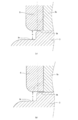
そこで、まず、従来技術として、前述の特許第3078625号の非対称のスリーブを用いて鋳造し、その後切削加工する手順について、図3に基づき簡単に説明する。
図3(a)に示すように、上型のピン部2pに、非対称のスリーブSのうちスリーブ端面の外周側が面取り部mとして大きく面取りされている方をクランク室側に向くようセットして下型3と型締めし鋳造する。そして鋳造が終えると、鋳造品を金型から取り出し、スリーブS内面を切削加工により一点鎖線に示すように切削した後、二点鎖線に示すようにスリーブS端面の開口部を面取り加工する。この方法によると、スリーブS端面と下型3との間の隙間に発生するバリが除去される。
これに対して、非対称のスリーブSのセット方向が逆向きになった場合には、図3(b)に示すように、スリーブS端面の外周側が大きく面取りされていない方がクランク室側に向くようになり、この状態で鋳造すると、スリーブS端面と下型3との間の隙間に0.6mm程度のバリが発生し、鋳造後のスリーブS内面の切削加工(一点鎖線)と、開口部側の面取り加工(二点鎖線)では、バリを完全に除去することができず、スリーブS端面の一部にバリが残ったままとなる。
なお、二点鎖線の開口部の面取り加工は、その後、シリンダブロックのスリーブS内にピストンを挿入してエンジンとして組み付ける際、ピストンの挿入を容易にする効果もあり、一点鎖線の内周面の切削加工や二点鎖線の開口部側の面取り加工は、従来から行われている加工手順である。
次に、本願発明に係るシリンダブロックの製造方法について説明する。
図1は、本発明の製造方法に使用される金型構造であり、この金型1は、上型2と下型3と横型4を備えるとともに、上型3にはスリーブSを装着するためのピン部2pが形成されている。
図1は、本発明の製造方法に使用される金型構造であり、この金型1は、上型2と下型3と横型4を備えるとともに、上型3にはスリーブSを装着するためのピン部2pが形成されている。
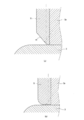
そして、このピン部2にセットされたスリーブS端面が対向する下型3には、図2に示すように、スリーブSの内側端面の一部に近接または当接する近・当接部3kと、スリーブSの端面からの距離が所定間隔hだけ幅広となる幅広部3zが形成され、この幅広部3zとスリーブS端面との間に入り込んだ溶湯が製品の一部として成形されるようにしている。
ここで、幅広部3zとスリーブS端面との所定間隔hは1.0~1.6mm程度が好ましく、本実施例では1.3mmとしている。
以上のような金型1を型締めし、図2(a)に示すように、キャビティ内に溶湯を充填して鋳造が終えると、金型1から鋳造品が取り出され、一点鎖線に示すように、スリーブSの内周面を所定量切削する切削加工が行われる。そしてその後、二点鎖線に示すように、スリーブSの開口部の面取り加工が行われ、この際、下型3の近・当接部3kと幅広部3zの境界部で成形された部分が含まれるようにしている。
このような製造方法において、仮に近・当接部3kとスリーブS端面との間にバリが発生していてもこれが除去されるようになり、特別な加工手順は不要である。
なお、一点鎖線のスリーブSの内周面の切削に引き続く二点鎖線のスリーブSの開口部の面取り加工は、図2(b)に示すような加工形態でもよく、この場合も同様な効果を奏する。
以上のような製造方法により、非対称のスリーブを使用するときのようにスリーブセット時の方向に注意を払う必要がなくなり、しかも、鋳造後の切削加工も通常の加工手順で特別な手順を採用する必要がないので便利である。
なお、本発明は以上のような実施形態に限定されるものではない。本発明の特許請求の範囲に記載した事項と実質的に同一の構成を有し、同一の作用効果を奏するものは本発明の技術的範囲に属する。
スリーブを鋳込んだシリンダブロックを製造する際、スリーブ端面のバリの発生を確実に防止でき、しかも鋳造、切削とも通常の手順で済むため、自動車エンジンの製造等において広い普及が期待される。
1…金型、2…上型、2p…ピン部、3…下型、3k…近・当接部、3z…幅広部、h…所定間隔、S…スリーブ。
Claims (2)
- 金型のピン部にセットしたスリーブを鋳造材料で鋳包んでシリンダブロックを鋳造した後、必要箇所を切削するようにしたシリンダブロックの製造方法であって、前記ピン部が形成される金型とは反対側の金型に、前記スリーブの内側端面の一部に近接または当接する近・当接部を形成するとともに、この近・当接部を除くスリーブの外側端面に対向する箇所に、スリーブ端面との距離が所定間隔だけ幅広となる幅広部を形成し、この金型で鋳造した鋳造品のスリーブの内周面を所定量切削加工する際、前記近・当接部と幅広部の境界部で成形された部分を合わせて切削することを特徴とするシリンダブロックの製造方法。
- 前記幅広部におけるスリーブ端面と対向する金型との間隔は、1.0~1.6mmであることを特徴とする請求項1に記載のシリンダブロックの製造方法。
Applications Claiming Priority (2)
| Application Number | Priority Date | Filing Date | Title |
|---|---|---|---|
| JP2012-204658 | 2012-09-18 | ||
| JP2012204658A JP2014057984A (ja) | 2012-09-18 | 2012-09-18 | シリンダブロックの製造方法 |
Publications (1)
| Publication Number | Publication Date |
|---|---|
| WO2014045642A1 true WO2014045642A1 (ja) | 2014-03-27 |
Family
ID=50340974
Family Applications (1)
| Application Number | Title | Priority Date | Filing Date |
|---|---|---|---|
| PCT/JP2013/064621 Ceased WO2014045642A1 (ja) | 2012-09-18 | 2013-05-27 | シリンダブロックの製造方法 |
Country Status (2)
| Country | Link |
|---|---|
| JP (1) | JP2014057984A (ja) |
| WO (1) | WO2014045642A1 (ja) |
Families Citing this family (2)
| Publication number | Priority date | Publication date | Assignee | Title |
|---|---|---|---|---|
| JP2017170531A (ja) * | 2016-03-18 | 2017-09-28 | 第一工業株式会社 | バリ取り装置 |
| JP7509717B2 (ja) | 2021-05-13 | 2024-07-02 | 株式会社クボタ | エンジン |
Citations (3)
| Publication number | Priority date | Publication date | Assignee | Title |
|---|---|---|---|---|
| JPS6281259A (ja) * | 1985-10-03 | 1987-04-14 | Mitsubishi Heavy Ind Ltd | ダイカスト方法 |
| JPH0599063A (ja) * | 1991-10-11 | 1993-04-20 | Honda Motor Co Ltd | シリンダスリーブ構造 |
| WO2005003540A1 (ja) * | 2003-07-07 | 2005-01-13 | Mitsubishi Jidosha Kogyo Kabushiki Kaisha | シリンダライナ鋳込みシリンダブロックの構造、シリンダブロックの製造方法、および同方法に用いられる鋳込み用シリンダライナ |
-
2012
- 2012-09-18 JP JP2012204658A patent/JP2014057984A/ja active Pending
-
2013
- 2013-05-27 WO PCT/JP2013/064621 patent/WO2014045642A1/ja not_active Ceased
Patent Citations (3)
| Publication number | Priority date | Publication date | Assignee | Title |
|---|---|---|---|---|
| JPS6281259A (ja) * | 1985-10-03 | 1987-04-14 | Mitsubishi Heavy Ind Ltd | ダイカスト方法 |
| JPH0599063A (ja) * | 1991-10-11 | 1993-04-20 | Honda Motor Co Ltd | シリンダスリーブ構造 |
| WO2005003540A1 (ja) * | 2003-07-07 | 2005-01-13 | Mitsubishi Jidosha Kogyo Kabushiki Kaisha | シリンダライナ鋳込みシリンダブロックの構造、シリンダブロックの製造方法、および同方法に用いられる鋳込み用シリンダライナ |
Also Published As
| Publication number | Publication date |
|---|---|
| JP2014057984A (ja) | 2014-04-03 |
Similar Documents
| Publication | Publication Date | Title |
|---|---|---|
| JP4446015B1 (ja) | シリンダブロック製造方法およびダミーライナ並びにダミーライナ鋳造方法 | |
| FR2990367A1 (fr) | Outillage de fabrication d'un noyau de fonderie pour une aube de turbomachine | |
| JP3274069B2 (ja) | クローズドデッキタイプシリンダブロック鋳造装置と該装置に用いられる砂中子との組合せ | |
| JP2019089075A (ja) | ダイカスト鋳造装置 | |
| WO2014045642A1 (ja) | シリンダブロックの製造方法 | |
| JP6324133B2 (ja) | アルミダイカスト工法及びダイカスト鋳放し製品 | |
| WO2012141176A1 (ja) | タイヤ加硫用モールドの製造方法およびタイヤ加硫用モールド | |
| JP2015174140A5 (ja) | ||
| KR101099504B1 (ko) | 다이캐스팅 금형 | |
| JP6351319B2 (ja) | 金型冷却構造及びその製造方法 | |
| JP6629588B2 (ja) | ダイカスト金型、ダイカスト金型を用いて作製された鋳造品、およびダイカスト金型を用いた鋳造品の作製方法 | |
| JP6400401B2 (ja) | 成形用金型、及び成形方法 | |
| JP5039635B2 (ja) | フランジ部付き鋳造部品及びその鋳造に用いる金型 | |
| JP5127040B2 (ja) | ダイカスト品の製造方法 | |
| KR20090050279A (ko) | 다이캐스팅 금형용 인서트 코어 | |
| JP3248896B2 (ja) | クロ−ズドデッキタイプシリンダブロック鋳造装置と該装置に用いられる砂中子との組合せ | |
| JP2009214162A (ja) | 鋳ぐるみ用中子および鋳ぐるみ鋳造方法 | |
| JP7621040B2 (ja) | 鋳造品の製造方法 | |
| JP4154754B2 (ja) | 複合金属部材の製造方法 | |
| JP6351320B2 (ja) | ダイカスト用鋳抜きピン構造 | |
| JP5516840B2 (ja) | シリンダヘッド鋳造型およびシリンダヘッド鋳造方法 | |
| JP2001003807A (ja) | シリンダスリーブ構造 | |
| JP2006055868A (ja) | 鋳造方法および鋳造用金型 | |
| JP2009006371A (ja) | 金型 | |
| JP3372885B2 (ja) | 鋳造用金型構造 |
Legal Events
| Date | Code | Title | Description |
|---|---|---|---|
| 121 | Ep: the epo has been informed by wipo that ep was designated in this application |
Ref document number: 13838560 Country of ref document: EP Kind code of ref document: A1 |
|
| NENP | Non-entry into the national phase |
Ref country code: DE |
|
| 122 | Ep: pct application non-entry in european phase |
Ref document number: 13838560 Country of ref document: EP Kind code of ref document: A1 |