WO2014041934A1 - レーザ治療装置 - Google Patents
レーザ治療装置 Download PDFInfo
- Publication number
- WO2014041934A1 WO2014041934A1 PCT/JP2013/071634 JP2013071634W WO2014041934A1 WO 2014041934 A1 WO2014041934 A1 WO 2014041934A1 JP 2013071634 W JP2013071634 W JP 2013071634W WO 2014041934 A1 WO2014041934 A1 WO 2014041934A1
- Authority
- WO
- WIPO (PCT)
- Prior art keywords
- irradiation
- unit
- light
- pattern
- image
- Prior art date
- Legal status (The legal status is an assumption and is not a legal conclusion. Google has not performed a legal analysis and makes no representation as to the accuracy of the status listed.)
- Ceased
Links
Images















Classifications
-
- A—HUMAN NECESSITIES
- A61—MEDICAL OR VETERINARY SCIENCE; HYGIENE
- A61F—FILTERS IMPLANTABLE INTO BLOOD VESSELS; PROSTHESES; DEVICES PROVIDING PATENCY TO, OR PREVENTING COLLAPSING OF, TUBULAR STRUCTURES OF THE BODY, e.g. STENTS; ORTHOPAEDIC, NURSING OR CONTRACEPTIVE DEVICES; FOMENTATION; TREATMENT OR PROTECTION OF EYES OR EARS; BANDAGES, DRESSINGS OR ABSORBENT PADS; FIRST-AID KITS
- A61F9/00—Methods or devices for treatment of the eyes; Devices for putting in contact-lenses; Devices to correct squinting; Apparatus to guide the blind; Protective devices for the eyes, carried on the body or in the hand
- A61F9/007—Methods or devices for eye surgery
- A61F9/008—Methods or devices for eye surgery using laser
- A61F9/00821—Methods or devices for eye surgery using laser for coagulation
- A61F9/00823—Laser features or special beam parameters therefor
-
- A—HUMAN NECESSITIES
- A61—MEDICAL OR VETERINARY SCIENCE; HYGIENE
- A61B—DIAGNOSIS; SURGERY; IDENTIFICATION
- A61B18/00—Surgical instruments, devices or methods for transferring non-mechanical forms of energy to or from the body
- A61B18/18—Surgical instruments, devices or methods for transferring non-mechanical forms of energy to or from the body by applying electromagnetic radiation, e.g. microwaves
- A61B18/20—Surgical instruments, devices or methods for transferring non-mechanical forms of energy to or from the body by applying electromagnetic radiation, e.g. microwaves using laser
-
- A—HUMAN NECESSITIES
- A61—MEDICAL OR VETERINARY SCIENCE; HYGIENE
- A61B—DIAGNOSIS; SURGERY; IDENTIFICATION
- A61B18/00—Surgical instruments, devices or methods for transferring non-mechanical forms of energy to or from the body
- A61B18/18—Surgical instruments, devices or methods for transferring non-mechanical forms of energy to or from the body by applying electromagnetic radiation, e.g. microwaves
- A61B18/20—Surgical instruments, devices or methods for transferring non-mechanical forms of energy to or from the body by applying electromagnetic radiation, e.g. microwaves using laser
- A61B18/203—Surgical instruments, devices or methods for transferring non-mechanical forms of energy to or from the body by applying electromagnetic radiation, e.g. microwaves using laser applying laser energy to the outside of the body
-
- A—HUMAN NECESSITIES
- A61—MEDICAL OR VETERINARY SCIENCE; HYGIENE
- A61F—FILTERS IMPLANTABLE INTO BLOOD VESSELS; PROSTHESES; DEVICES PROVIDING PATENCY TO, OR PREVENTING COLLAPSING OF, TUBULAR STRUCTURES OF THE BODY, e.g. STENTS; ORTHOPAEDIC, NURSING OR CONTRACEPTIVE DEVICES; FOMENTATION; TREATMENT OR PROTECTION OF EYES OR EARS; BANDAGES, DRESSINGS OR ABSORBENT PADS; FIRST-AID KITS
- A61F9/00—Methods or devices for treatment of the eyes; Devices for putting in contact-lenses; Devices to correct squinting; Apparatus to guide the blind; Protective devices for the eyes, carried on the body or in the hand
- A61F9/007—Methods or devices for eye surgery
- A61F9/008—Methods or devices for eye surgery using laser
-
- A—HUMAN NECESSITIES
- A61—MEDICAL OR VETERINARY SCIENCE; HYGIENE
- A61F—FILTERS IMPLANTABLE INTO BLOOD VESSELS; PROSTHESES; DEVICES PROVIDING PATENCY TO, OR PREVENTING COLLAPSING OF, TUBULAR STRUCTURES OF THE BODY, e.g. STENTS; ORTHOPAEDIC, NURSING OR CONTRACEPTIVE DEVICES; FOMENTATION; TREATMENT OR PROTECTION OF EYES OR EARS; BANDAGES, DRESSINGS OR ABSORBENT PADS; FIRST-AID KITS
- A61F9/00—Methods or devices for treatment of the eyes; Devices for putting in contact-lenses; Devices to correct squinting; Apparatus to guide the blind; Protective devices for the eyes, carried on the body or in the hand
- A61F9/007—Methods or devices for eye surgery
- A61F9/008—Methods or devices for eye surgery using laser
- A61F9/009—Auxiliary devices making contact with the eyeball and coupling in laser light, e.g. goniolenses
-
- A—HUMAN NECESSITIES
- A61—MEDICAL OR VETERINARY SCIENCE; HYGIENE
- A61B—DIAGNOSIS; SURGERY; IDENTIFICATION
- A61B18/00—Surgical instruments, devices or methods for transferring non-mechanical forms of energy to or from the body
- A61B2018/00982—Surgical instruments, devices or methods for transferring non-mechanical forms of energy to or from the body combined with or comprising means for visual or photographic inspections inside the body, e.g. endoscopes
-
- A—HUMAN NECESSITIES
- A61—MEDICAL OR VETERINARY SCIENCE; HYGIENE
- A61B—DIAGNOSIS; SURGERY; IDENTIFICATION
- A61B18/00—Surgical instruments, devices or methods for transferring non-mechanical forms of energy to or from the body
- A61B18/18—Surgical instruments, devices or methods for transferring non-mechanical forms of energy to or from the body by applying electromagnetic radiation, e.g. microwaves
- A61B18/20—Surgical instruments, devices or methods for transferring non-mechanical forms of energy to or from the body by applying electromagnetic radiation, e.g. microwaves using laser
- A61B2018/2015—Miscellaneous features
- A61B2018/2025—Miscellaneous features with a pilot laser
-
- A—HUMAN NECESSITIES
- A61—MEDICAL OR VETERINARY SCIENCE; HYGIENE
- A61B—DIAGNOSIS; SURGERY; IDENTIFICATION
- A61B18/00—Surgical instruments, devices or methods for transferring non-mechanical forms of energy to or from the body
- A61B18/18—Surgical instruments, devices or methods for transferring non-mechanical forms of energy to or from the body by applying electromagnetic radiation, e.g. microwaves
- A61B18/20—Surgical instruments, devices or methods for transferring non-mechanical forms of energy to or from the body by applying electromagnetic radiation, e.g. microwaves using laser
- A61B2018/2035—Beam shaping or redirecting; Optical components therefor
- A61B2018/20351—Scanning mechanisms
- A61B2018/20359—Scanning mechanisms by movable mirrors, e.g. galvanometric
-
- A—HUMAN NECESSITIES
- A61—MEDICAL OR VETERINARY SCIENCE; HYGIENE
- A61B—DIAGNOSIS; SURGERY; IDENTIFICATION
- A61B3/00—Apparatus for testing the eyes; Instruments for examining the eyes
- A61B3/10—Objective types, i.e. instruments for examining the eyes independent of the patients' perceptions or reactions
- A61B3/12—Objective types, i.e. instruments for examining the eyes independent of the patients' perceptions or reactions for looking at the eye fundus, e.g. ophthalmoscopes
-
- A—HUMAN NECESSITIES
- A61—MEDICAL OR VETERINARY SCIENCE; HYGIENE
- A61B—DIAGNOSIS; SURGERY; IDENTIFICATION
- A61B3/00—Apparatus for testing the eyes; Instruments for examining the eyes
- A61B3/10—Objective types, i.e. instruments for examining the eyes independent of the patients' perceptions or reactions
- A61B3/14—Arrangements specially adapted for eye photography
-
- A—HUMAN NECESSITIES
- A61—MEDICAL OR VETERINARY SCIENCE; HYGIENE
- A61F—FILTERS IMPLANTABLE INTO BLOOD VESSELS; PROSTHESES; DEVICES PROVIDING PATENCY TO, OR PREVENTING COLLAPSING OF, TUBULAR STRUCTURES OF THE BODY, e.g. STENTS; ORTHOPAEDIC, NURSING OR CONTRACEPTIVE DEVICES; FOMENTATION; TREATMENT OR PROTECTION OF EYES OR EARS; BANDAGES, DRESSINGS OR ABSORBENT PADS; FIRST-AID KITS
- A61F9/00—Methods or devices for treatment of the eyes; Devices for putting in contact-lenses; Devices to correct squinting; Apparatus to guide the blind; Protective devices for the eyes, carried on the body or in the hand
- A61F9/007—Methods or devices for eye surgery
- A61F9/008—Methods or devices for eye surgery using laser
- A61F2009/00844—Feedback systems
-
- A—HUMAN NECESSITIES
- A61—MEDICAL OR VETERINARY SCIENCE; HYGIENE
- A61F—FILTERS IMPLANTABLE INTO BLOOD VESSELS; PROSTHESES; DEVICES PROVIDING PATENCY TO, OR PREVENTING COLLAPSING OF, TUBULAR STRUCTURES OF THE BODY, e.g. STENTS; ORTHOPAEDIC, NURSING OR CONTRACEPTIVE DEVICES; FOMENTATION; TREATMENT OR PROTECTION OF EYES OR EARS; BANDAGES, DRESSINGS OR ABSORBENT PADS; FIRST-AID KITS
- A61F9/00—Methods or devices for treatment of the eyes; Devices for putting in contact-lenses; Devices to correct squinting; Apparatus to guide the blind; Protective devices for the eyes, carried on the body or in the hand
- A61F9/007—Methods or devices for eye surgery
- A61F9/008—Methods or devices for eye surgery using laser
- A61F2009/00861—Methods or devices for eye surgery using laser adapted for treatment at a particular location
- A61F2009/00863—Retina
-
- A—HUMAN NECESSITIES
- A61—MEDICAL OR VETERINARY SCIENCE; HYGIENE
- A61F—FILTERS IMPLANTABLE INTO BLOOD VESSELS; PROSTHESES; DEVICES PROVIDING PATENCY TO, OR PREVENTING COLLAPSING OF, TUBULAR STRUCTURES OF THE BODY, e.g. STENTS; ORTHOPAEDIC, NURSING OR CONTRACEPTIVE DEVICES; FOMENTATION; TREATMENT OR PROTECTION OF EYES OR EARS; BANDAGES, DRESSINGS OR ABSORBENT PADS; FIRST-AID KITS
- A61F9/00—Methods or devices for treatment of the eyes; Devices for putting in contact-lenses; Devices to correct squinting; Apparatus to guide the blind; Protective devices for the eyes, carried on the body or in the hand
- A61F9/007—Methods or devices for eye surgery
- A61F9/008—Methods or devices for eye surgery using laser
- A61F2009/00878—Planning
-
- A—HUMAN NECESSITIES
- A61—MEDICAL OR VETERINARY SCIENCE; HYGIENE
- A61F—FILTERS IMPLANTABLE INTO BLOOD VESSELS; PROSTHESES; DEVICES PROVIDING PATENCY TO, OR PREVENTING COLLAPSING OF, TUBULAR STRUCTURES OF THE BODY, e.g. STENTS; ORTHOPAEDIC, NURSING OR CONTRACEPTIVE DEVICES; FOMENTATION; TREATMENT OR PROTECTION OF EYES OR EARS; BANDAGES, DRESSINGS OR ABSORBENT PADS; FIRST-AID KITS
- A61F9/00—Methods or devices for treatment of the eyes; Devices for putting in contact-lenses; Devices to correct squinting; Apparatus to guide the blind; Protective devices for the eyes, carried on the body or in the hand
- A61F9/007—Methods or devices for eye surgery
- A61F9/008—Methods or devices for eye surgery using laser
- A61F2009/00878—Planning
- A61F2009/00882—Planning based on topography
-
- A—HUMAN NECESSITIES
- A61—MEDICAL OR VETERINARY SCIENCE; HYGIENE
- A61F—FILTERS IMPLANTABLE INTO BLOOD VESSELS; PROSTHESES; DEVICES PROVIDING PATENCY TO, OR PREVENTING COLLAPSING OF, TUBULAR STRUCTURES OF THE BODY, e.g. STENTS; ORTHOPAEDIC, NURSING OR CONTRACEPTIVE DEVICES; FOMENTATION; TREATMENT OR PROTECTION OF EYES OR EARS; BANDAGES, DRESSINGS OR ABSORBENT PADS; FIRST-AID KITS
- A61F9/00—Methods or devices for treatment of the eyes; Devices for putting in contact-lenses; Devices to correct squinting; Apparatus to guide the blind; Protective devices for the eyes, carried on the body or in the hand
- A61F9/007—Methods or devices for eye surgery
- A61F9/008—Methods or devices for eye surgery using laser
- A61F2009/00897—Scanning mechanisms or algorithms
-
- A—HUMAN NECESSITIES
- A61—MEDICAL OR VETERINARY SCIENCE; HYGIENE
- A61F—FILTERS IMPLANTABLE INTO BLOOD VESSELS; PROSTHESES; DEVICES PROVIDING PATENCY TO, OR PREVENTING COLLAPSING OF, TUBULAR STRUCTURES OF THE BODY, e.g. STENTS; ORTHOPAEDIC, NURSING OR CONTRACEPTIVE DEVICES; FOMENTATION; TREATMENT OR PROTECTION OF EYES OR EARS; BANDAGES, DRESSINGS OR ABSORBENT PADS; FIRST-AID KITS
- A61F2250/00—Special features of prostheses classified in groups A61F2/00 - A61F2/26 or A61F2/82 or A61F9/00 or A61F11/00 or subgroups thereof
- A61F2250/0058—Additional features; Implant or prostheses properties not otherwise provided for
- A61F2250/0096—Markers and sensors for detecting a position or changes of a position of an implant, e.g. RF sensors, ultrasound markers
- A61F2250/0097—Visible markings, e.g. indicia
Definitions
- This invention relates to a laser treatment apparatus used in the ophthalmic field.
- Laser treatment equipment is used for photocoagulation treatment of the retina.
- the treatment laser light is irradiated to the fundus position (treatment position) on which the aiming pattern is projected.
- treatment position the fundus position
- What was comprised is known (for example, refer patent documents 1 and 2).
- the target treatment position may not be irradiated with the treatment laser light depending on the treatment position, the aiming pattern, and the condition of the eye to be examined. There is.
- a part of the treatment laser beam may be blocked by the iris. Conceivable. At this time, the iris may be damaged depending on the type of the treatment laser beam.
- the treatment laser beam when treating the periphery of the fundus, the treatment laser beam may be blurred due to the influence of aberrations of the apparatus optical system, contact lens, eyeball optical system, etc., and the size of the projected image on the fundus may increase. is there.
- the projection image may be enlarged only for some of the plurality of treatment laser beams irradiated in a predetermined pattern. If it does so, the energy density of the therapeutic laser beam by which the projection image was expanded becomes lower than other therapeutic laser beams, and there exists a possibility that a therapeutic effect may fall.
- An object of the present invention is to improve the safety of ophthalmic laser treatment.
- Another object of the present invention is to prevent the effect of ophthalmic laser treatment from being reduced.
- the invention according to claim 1 is acquired by an imaging system that images the eye to be examined, an irradiation system that irradiates the fundus of the eye to be examined with a predetermined pattern of aiming light and a therapeutic laser beam, and the imaging system.
- An irradiation pattern determination unit that determines an irradiation pattern of the therapeutic laser beam based on the captured image of the eye to be examined and the predetermined pattern, and the irradiation so that the therapeutic laser beam is irradiated with the determined irradiation pattern
- a laser treatment apparatus having a control unit for controlling the system.
- the invention according to claim 2 is the laser treatment apparatus according to claim 1, wherein the imaging system images the eye to be examined in a state in which a predetermined pattern of aiming light is irradiated. An image is acquired, and the irradiation pattern determination unit determines the irradiation pattern based on the captured image and the predetermined pattern.
- the invention according to claim 3 is the laser treatment apparatus according to claim 2, wherein the irradiation pattern determination unit analyzes the captured image to obtain a projected image of the aiming light in the captured image. A projection image specifying unit to be specified is included, and the irradiation pattern is determined based on the specified projection image and the predetermined pattern.
- the invention according to claim 4 is the laser treatment apparatus according to claim 3, wherein the captured image is an image of the fundus of the eye to be examined, and the irradiation pattern determination unit is indicated by the predetermined pattern
- the irradiation pattern is determined by including a difference specifying unit that specifies a difference between the arrangement and the arrangement of the projection images specified by the projection image specifying unit, and excluding at least a portion corresponding to the difference from the predetermined pattern It is characterized by performing.
- the invention according to claim 5 is the laser treatment apparatus according to claim 3, wherein the captured image is an image of the fundus of the eye to be examined, and the irradiation pattern determination unit is the projection image specifying unit.
- the irradiation pattern is determined by excluding at least a part of the projection image based on pixel information corresponding to the projection image specified by the above.
- the invention according to claim 6 is the laser treatment apparatus according to claim 5, wherein the irradiation pattern determination unit has a relatively low brightness among the projection images specified by the projection image specification unit.
- the irradiation pattern is determined by excluding at least a portion corresponding to the selected projection image from the predetermined pattern, including a first selection unit that selects a projection image.
- the invention according to claim 7 is the laser treatment apparatus according to claim 5, wherein the irradiation pattern determination unit has a relatively large size among the projection images specified by the projection image specification unit.
- a second selection unit that selects a projection image is included, and the irradiation pattern is determined by excluding at least a portion corresponding to the selected projection image from the predetermined pattern.
- the invention according to claim 8 is the laser treatment apparatus according to claim 5, wherein the irradiation pattern determination unit selects a projection image having a different shape from among the projection images specified by the projection image specifying unit. The irradiation pattern is determined by excluding at least a portion corresponding to the selected projection image from the predetermined pattern, including a third selection unit to be selected.
- the invention according to claim 9 is the laser treatment apparatus according to claim 1, wherein the imaging system images an eye to be examined in a state where a contact lens for laser treatment is in contact.
- the captured image is acquired, and the irradiation pattern determination unit determines the irradiation pattern based on the captured image and the predetermined pattern.
- the invention according to claim 10 is the laser treatment apparatus according to claim 9, wherein the irradiation pattern determination unit includes the captured image in a state where the contact lens is in contact with the predetermined pattern. On the basis of the above, the irradiation pattern is determined by excluding a part of the predetermined pattern.
- the invention according to claim 11 is the laser treatment apparatus according to claim 9 or claim 10, wherein the irradiation pattern determination unit includes the irradiation system, the contact lens, and the like based on the captured image.
- a relative position information acquisition unit for acquiring relative position information between the two, and determining the irradiation pattern based on the acquired relative position information and the predetermined pattern.
- the invention according to claim 12 is the laser treatment apparatus according to claim 11, wherein the irradiation pattern determination unit applies the predetermined pattern based on the acquired relative position information and the predetermined pattern.
- An aberration amount acquisition unit that acquires the amount of aberration applied to the included aiming light is included, and the irradiation pattern is determined based on the acquired amount of aberration.
- the invention according to claim 13 is the laser treatment apparatus according to claim 12, further comprising a storage unit that stores in advance first aberration information indicating each aberration of the one or more contact lenses.
- the aberration amount acquisition unit obtains an incident position of the aiming light included in the predetermined pattern with respect to the contact lens based on the relative position information and the predetermined pattern, and determines the incident position and the first aberration information. Based on the above, an amount of aberration given to the aiming light is acquired.
- the invention according to claim 14 is the laser treatment apparatus according to claim 13, wherein the storage unit is a second aberration indicating a standard value of the aberration of the human eye or an actually measured value of the aberration of the eye to be examined. Information is stored in advance, and the aberration amount acquisition unit acquires the aberration amount based on the incident position, the first aberration information, and the second aberration information.
- the invention according to claim 15 is the laser treatment apparatus according to any one of claims 9 to 14, wherein one or more markers are provided at a position on the imaging system side of the contact lens.
- the irradiation pattern determination unit includes a marker image specifying unit that specifies the image of the marker in the captured image by analyzing the captured image, and the specified marker image and the predetermined pattern Based on the above, the irradiation pattern is determined.
- the invention according to claim 16 is the laser treatment apparatus according to claim 15, wherein the irradiation pattern determination unit is based on the position of the image of the marker in the captured image and the predetermined pattern, The irradiation pattern is determined.
- the invention according to claim 17 is the laser treatment apparatus according to claim 15, wherein the irradiation pattern determination unit is based on the shape of the marker image and the predetermined pattern in the captured image. The irradiation pattern is determined.
- the invention according to claim 18 is the laser treatment apparatus according to any one of claims 9 to 14, wherein the imaging system is configured to irradiate the contact lens with a parallel light beam. The photographed image is acquired by photographing the eye to be examined, and the irradiation pattern determination unit determines the irradiation pattern based on the reflected image of the parallel light flux and the predetermined pattern in the photographed image. It is characterized by that.
- the invention according to claim 19 is directed to an irradiation system for irradiating the fundus of the subject's eye with a predetermined pattern of aiming light and therapeutic laser light, and the return of the predetermined pattern of aiming light from the subject's eye.
- a detection unit that detects light
- an irradiation pattern determination unit that determines an irradiation pattern of the therapeutic laser beam based on the detection result of the return light and the predetermined pattern; and the therapeutic laser beam based on the determined irradiation pattern
- a laser treatment apparatus having a control unit for controlling the irradiation system to irradiate.
- the invention according to claim 20 is the laser treatment apparatus according to claim 19, wherein the detection unit detects the light amount of the return light, and the irradiation pattern determination unit detects the light amount detection result. Based on the predetermined pattern, a fourth selection unit that selects an aiming light having a relatively small amount of return light among the aiming light of the predetermined pattern, and at least a portion corresponding to the selected aiming light is extracted from the predetermined pattern. The irradiation pattern is determined by excluding it.
- the invention according to claim 21 is the laser treatment apparatus according to any one of claims 4 to 8, 10, and 20, wherein the predetermined pattern is formed by the irradiation pattern determination unit.
- the irradiation pattern determination unit sets at least one of the irradiation positions not excluded as a new high-intensity The irradiation position is set, and the control unit controls the irradiation system so that the new high-intensity irradiation position is irradiated with a therapeutic laser beam having a higher intensity than other irradiation positions.
- the invention according to claim 22 is the laser treatment apparatus according to any one of claims 1 to 21, wherein the irradiation system changes the irradiation position of the treatment laser beam on the fundus.
- the control unit controls the scanning unit based on the irradiation pattern determined by the irradiation pattern determination unit.
- the invention according to claim 23 is the laser treatment apparatus according to any one of claims 4 to 8, claim 10, claim 20 and claim 21, wherein the irradiation system comprises: A scanning unit for changing the irradiation position of the treatment laser beam on the fundus, and a path of the treatment laser beam for switching between a first path toward the eye to be examined and a second path not toward the eye to be examined.
- a path switching unit wherein the control unit controls the scanning unit based on the predetermined pattern, and synchronizes with the control of the scanning unit corresponding to a portion excluded from the predetermined pattern.
- the route switching unit is controlled to switch the route to the second route.
- the invention according to claim 24 is the laser treatment apparatus according to claim 23, wherein the path switching unit is provided on a path of the treatment laser light and is a reflection surface that reflects the treatment laser light. It includes a first reflecting member whose direction can be changed, and the control unit switches the path of the treatment laser light by changing the direction of the reflecting surface of the first reflecting member.
- the invention according to claim 25 is the laser treatment apparatus according to any one of claims 1 to 21, wherein the irradiation system is movable along its optical axis, and the fundus Including a focusing lens for changing the size of the projection spot of the therapeutic laser beam in which the control unit moves the focusing lens based on the irradiation pattern determined by the irradiation pattern determination unit .
- the invention according to claim 26 is the laser treatment apparatus according to any one of claims 1 to 21, wherein the irradiation system is an astigmatism of a projection spot of treatment laser light on the fundus.
- a variable cross cylinder lens for correcting aberration is included, and the control unit controls the variable cross cylinder lens based on the irradiation pattern determined by the irradiation pattern determination unit.
- the invention according to claim 27 is the laser treatment apparatus according to any one of claims 1 to 21, wherein the irradiation system has a shape of a reflecting surface that reflects the treatment laser beam.
- the control unit includes a changeable second reflection member, and the control unit changes the shape of the reflection surface of the second reflection member based on the irradiation pattern determined by the irradiation pattern determination unit.
- the invention according to claim 28 is the laser treatment apparatus according to any one of claims 1 to 18, wherein the notification unit performs notification based on a captured image acquired by the imaging system. It is characterized by having.
- the invention according to claim 29 is the laser treatment apparatus according to claim 19 or claim 20, further comprising a notification unit that performs notification based on the detection result of the return light by the detection unit.
- the invention described in claim 30 is an imaging system for imaging the eye to be examined, an irradiation system for irradiating the fundus of the eye to be examined with a predetermined pattern of aiming light and a therapeutic laser beam, and the imaging system. It is a laser therapy apparatus which has an alerting
- the invention described in claim 31 is directed to an irradiation system that irradiates the fundus of the subject's eye with a predetermined pattern of aiming light and therapeutic laser light, and the return of the predetermined pattern of aiming light from the subject's eye.
- It is a laser treatment apparatus which has a detection part which detects light, and a report part which reports based on a detection result of the return light by the detection part.
- the laser treatment apparatus it is possible to improve the safety of the ophthalmic laser treatment.
- the laser treatment apparatus it is possible to prevent the effect of ophthalmic laser treatment from being reduced.
- the direction from the device optical system toward the patient is the forward direction, and the opposite direction is the backward direction.
- the horizontal direction orthogonal to the front direction is the left-right direction.
- the direction orthogonal to both the front-rear direction and the left-right direction is defined as the up-down direction.
- the laser treatment apparatus 1 is used for performing laser treatment on the fundus oculi Ef of the eye E to be examined.
- the laser treatment apparatus 1 includes a light source unit 2, a slit lamp 3, an optical fiber 4, a processing unit 5, and an operation unit 6.
- a surgical microscope, a mirror, an intraocular observation device, or the like may be used.
- the light source unit 2 and the slit lamp 3 are optically connected via an optical fiber 4.
- the optical fiber 4 has one or more light guide paths.
- the light source unit 2 and the processing unit 5 are connected so that signals can be transmitted.
- the slit lamp 3 and the processing unit 5 are connected so that signals can be transmitted.
- the operation unit 6 and the processing unit 5 are connected so that signals can be transmitted.
- the signal transmission form may be wired or wireless.
- the processing unit 5 is a computer that operates in cooperation with hardware and software. The processing executed by the processing unit 5 will be described later.
- the operation unit 6 includes various hardware keys and / or software keys (GUI). Examples of hardware keys include buttons, handles, and knobs provided on the slit lamp 3, and keyboard pointing devices (such as a mouse and a trackball) provided on a computer (such as the processing unit 5) connected to the slit lamp 3. There are also foot switches and operation panels provided separately.
- the software key is displayed on, for example, the slit lamp 3 or a display device provided in the computer.
- the light source unit 2 generates light irradiated to the fundus oculi Ef.
- the light source unit 2 includes an aiming light source 2a, a therapeutic laser light source 2b, a galvano mirror 2c, and a light shielding plate 2d.
- members other than the members shown in FIG. 1 can be provided in the light source unit 2.
- an optical element (such as a lens) for causing the light generated by the light source unit 2 to enter the end face of the optical fiber 4 can be provided immediately before the optical fiber 4.
- the aiming light source 2a generates aiming light LA for aiming at a site where laser treatment is performed.
- An arbitrary light source is used as the aiming light source 2a.
- a light source for emitting a recognizable visible light by the operator's eye E 0 (a laser light source, light emitting diode, or the like) is used as an aiming light source 2a.
- a light source (laser light source, light emitting diode, or the like) that emits light in a wavelength band in which the imaging element for acquiring the captured image has sensitivity is used.
- the aiming light source 2a Used as the aiming light source 2a.
- the aiming light LA is guided to the galvanometer mirror 2c.
- the operation of the aiming light source 2a is controlled by the processing unit 5.
- the treatment laser light source 2b emits light (treatment laser light LT) used for laser treatment of the fundus oculi Ef.
- the therapeutic laser beam LT may be a visible laser beam or an invisible laser beam depending on the application.
- the therapeutic laser light source 2b may be a single laser light source or a plurality of laser light sources that emit laser beams of different wavelength bands.
- the therapeutic laser beam LT is guided to the galvanometer mirror 2c.
- the operation of the treatment laser light source 2 b is controlled by the processing unit 5.
- the galvano mirror 2c includes a mirror having a reflecting surface and an actuator that changes the direction of the mirror (the direction of the reflecting surface).
- the aiming light LA and the treatment laser light LT reach the same position on the reflection surface of the galvanometer mirror 2c.
- the aiming light LA and the therapeutic laser light LT may be collectively referred to as “irradiation light”.
- the direction of the galvano mirror 2c (the reflection surface thereof) is at least a direction in which the irradiation light is reflected toward the optical fiber 4 (irradiation direction) and a direction in which the irradiation light is reflected toward the light shielding plate 2d (stop direction). And changed.
- the operation of the galvano mirror 2 c is controlled by the processing unit 5.
- the light shielding plate 2d is a member made of, for example, a material and / or form that absorbs irradiation light, and has a light shielding effect.
- the aiming light source 2a and the therapeutic laser light source 2b each continuously generate light.
- the galvano mirror 2c is arranged in the irradiation direction, so that the eye E is irradiated with the irradiation light.
- the irradiation of the irradiation light with respect to the eye E to be examined is stopped by arranging the galvanometer mirror 2c in the stop direction.
- the slit lamp 3 is a device used for observing the anterior eye portion and the fundus oculi Ef of the eye E. More specifically, the slit lamp 3 is an ophthalmologic apparatus for illuminating the eye E with slit light and magnifying the irradiation field. Note that “observation” includes one or both of observation with the naked eye and observation of a captured image with an image sensor. The slit lamp 3 of this embodiment enables observation with the naked eye and also enables photographing of the eye E to be examined.
- the slit lamp 3 includes an illumination unit 3a, an observation unit 3b, an eyepiece unit 3c, and a laser irradiation unit 3d.
- the illumination system 3 shown in FIG. 2 is stored in the illumination unit 3a.
- An observation system 30 is stored in the observation unit 3b and the eyepiece unit 3c.
- a laser irradiation system 50 is stored in the laser irradiation unit 3d.
- the slit lamp 3 is provided with operation members such as a lever, a handle, a button, and a knob as in the conventional case. These operation members are functionally included in the operation unit 6.
- the processing unit 5 that receives a signal from the operation unit 6 controls the slit lamp 3, but only a mechanism that operates using such an electric driving force. Alternatively, a mechanism that operates using the driving force applied by the operator can be applied.
- FIG. 2 shows a contact lens CL used for laser treatment of the fundus oculi Ef.
- the slit lamp 3 includes an illumination system 10, an observation system 30, and a laser irradiation system 50.
- the illumination system 10 outputs illumination light for observing the eye E.
- the illumination unit 3a is configured to be able to change the direction of the optical axis (illumination optical axis) 10a of the illumination system 10 in the horizontal direction and the vertical direction. Thereby, the illumination direction of the eye E can be arbitrarily changed.
- the illumination system 10 includes a light source 11, a condenser lens 12, filters 13, 14 and 15, a slit diaphragm 16, imaging lenses 17, 18 and 19, and a deflecting member 20.
- the light source 11 outputs illumination light.
- a plurality of light sources may be provided in the illumination system 10.
- a light source halogen lamp, LED, etc.
- a light source xenon lamp, LED, etc.
- a light source for corneal observation and a light source for fundus observation may be provided separately.
- the condenser lens 12 is a lens (system) that collects the light output from the light source 11. The operation of the light source 11 is controlled by the processing unit 5.
- the filters 13 to 15 are optical elements each having an action of removing or weakening a specific component of illumination light.
- Examples of the filters 13 to 15 include a blue filter, a non-red filter, a dark filter, a heat filter, a corneal fluorescent filter, a color temperature conversion filter, a color rendering conversion filter, an ultraviolet cut filter, and an infrared cut filter.
- Each filter 13 to 15 can be inserted into and removed from the optical path of the illumination light. Insertion / removal of the filters 13 to 15 is controlled by the processing unit 5.
- the slit diaphragm 16 forms a slit for generating slit light (slit light).
- the slit diaphragm 16 has a pair of slit blades.
- the slit width is changed by changing the interval between the slit blades.
- a diaphragm member other than the slit diaphragm 16 can be provided in the illumination system 10.
- the diaphragm member include an illumination diaphragm for changing the amount of illumination light, and an illumination field diaphragm for changing the size of the illumination field.
- An example of such a member is a liquid crystal shutter.
- the operations of the slit diaphragm 16, the illumination diaphragm, the illumination field diaphragm, and the liquid crystal shutter are controlled by the processing unit 5.
- the imaging lenses 17, 18 and 19 are lens systems for forming an image of illumination light.
- the deflecting member 20 deflects the illumination light that has passed through the imaging lenses 17 to 19 and irradiates the eye E to be examined.
- a diffuser plate can be provided in the rear stage of the deflection member 20 so as to be detachable.
- the diffusing plate diffuses the illumination light to make the brightness of the illumination field uniform.
- a background light source that illuminates the background area of the illumination field with illumination light can be provided.
- Observation system 30 is an optical system that guides the surgeon's eye E 0 the reflected light of the illumination light by the eye to be examined E.
- the observation system 30 has a pair of left and right optical systems that enable observation with both left and right eyes. Since the left and right optical systems have substantially the same configuration, only one optical system is shown in FIG.
- the observation unit 3b is configured to be able to change the direction of the optical axis (observation optical axis) 30a of the observation system 30 in the horizontal direction and the vertical direction. Thereby, the observation direction of the eye E can be arbitrarily changed.
- the observation system 30 includes an objective lens 31, variable power lenses 32 and 33, a protective filter 34, an imaging lens 35, an erecting prism 36, a field stop 37, and an eyepiece lens 38.
- the observation system 30 is provided with a photographing system described later.
- the objective lens 31 is disposed at a position facing the eye E.
- the objective lens 31 may be common to the left and right optical systems, or may be provided separately on the left and right.
- the variable power lenses 32 and 33 constitute a variable power optical system (zoom lens system).
- the variable power lenses 32 and 33 are movable along the observation optical axis 30a.
- magnification field angle
- the magnification is changed, for example, by manually operating a magnification changing knob provided in the observation unit 3b.
- the processing unit 5 may control the magnification based on an operation by a switch or the like included in the operation unit 6.
- variable magnification optical system a plurality of variable magnification lens groups that can be selectively inserted into the optical path of the observation system 30 may be provided. These variable power lens groups are configured to give different magnifications.
- a variable power lens group disposed in the optical path of the observation system 30 is used as the variable power lenses 32 and 33. Changing the magnification, that is, switching the zoom lens group disposed in the optical path of the observation system 30 is performed, for example, by manually operating a magnification change knob provided in the observation unit 3b.
- the protective filter 34 is a filter that shields the laser light applied to the eye E. Thereby, it is possible to protect the operator's eye E 0 from the laser light.
- the protective filter 34 is inserted into the optical path in response to a start trigger of laser treatment (or laser output), for example. During normal observation, the protective filter 34 is retracted from the optical path. The insertion / removal of the protective filter 34 is controlled by the processing unit 5.
- the imaging lens 35 is a lens (system) that forms an image of the eye E to be examined.
- the erecting prism 36 is an optical member that converts an image observed through the eyepiece lens 37 into an erecting image, and includes prisms 36a and 36b.
- the eyepiece 37 moves integrally with the erecting prism 36.
- the erecting prism 36 and the eyepiece 37 are stored in the eyepiece 3c.
- Other members constituting the observation system 30 are stored in the observation unit 3b.
- the imaging system includes an imaging device 42 provided on an optical path branched from the observation optical axis 30a. This branching is realized by a beam splitter (half mirror or the like) 41 provided between the imaging lens 35 and the erecting prism 36. That is, the imaging system in this example includes the objective lens 31, the variable power lenses 32 and 33, the protection filter 34, the imaging lens 35, the beam splitter 41, and the imaging device 42.
- the imaging device 42 includes an imaging element such as a CCD image sensor or a CMOS image sensor.
- the imaging device 42 may include an optical element such as a lens.
- the imaging device 42 (the imaging device described above) has sensitivity in the wavelength band of the irradiation light (the aiming light LA and / or the therapeutic laser light LT). Therefore, when photographing is performed by the imaging device 42 in a state in which the irradiation light is irradiated on the fundus oculi Ef, a projection pattern of the irradiation light on the fundus oculi Ef is depicted in the captured image. Further, the imaging device 42 may have sensitivity in the wavelength band of illumination light from the illumination system 10. In that case, the form of the fundus oculi Ef (that is, the front image of the fundus oculi Ef) and the projection pattern of the irradiation light are depicted in the captured image.
- the subject of imaging using the imaging device 42 is not limited to the fundus oculi Ef but may be the anterior segment. Selection of a subject to be photographed by the imaging device 42 is performed, for example, by controlling the imaging lens 35 or a lens inside the imaging device 42.
- the laser irradiation system 50 is an optical system that guides the irradiation light transmitted from the light source unit 2 to the slit lamp 3 via the optical fiber 4 to the eye E to be examined.
- the laser irradiation system 50 includes a collimator lens 51, a galvano scanner 52, a mirror 53, relay lenses 54 and 55, a mirror 56, a collimator lens 57, and a deflection member 58.
- the collimator lens 51 converts the irradiation light output from the optical fiber 4 into a parallel light flux.
- the galvano scanner 52 deflects the irradiation light two-dimensionally.
- the galvano scanner 52 includes, for example, a galvanometer mirror for deflecting irradiation light in the left-right direction and a galvanometer mirror for deflecting illumination light in the up-down direction. In these galvanometer mirrors, the deflectable directions of the reflecting surfaces are orthogonal to each other. By changing the directions of these galvanometer mirrors independently, two-dimensional deflection of the irradiation light is realized.
- the operation of the galvano scanner 52 is controlled by the processing unit 5.
- the mirror 53 reflects the irradiation light passing through the galvano scanner 52 and changes its traveling direction.
- the relay lenses 54 and 55 relay the irradiation light reflected by the mirror 53.
- the mirror 56 reflects the irradiation light that has passed through the relay lenses 54 and 55 and changes its traveling direction.
- the collimator lens 57 turns the irradiation light that has passed through the relay lenses 54 and 55 into a convergent light beam.
- the deflection member 58 is disposed behind the objective lens 31 and deflects the irradiation light that has passed through the collimator lens 57 to irradiate the eye E to be examined.
- the pattern of irradiation light will be described. There are various conditions (irradiation conditions) in the pattern of irradiation light.
- a projection image of irradiation light (that is, an irradiation range of irradiation light on the fundus) is called a spot.
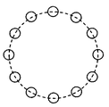
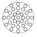
- Irradiation conditions include multiple spot arrays (array conditions), array sizes (array size conditions), array orientations (array direction conditions), spot sizes (spot size conditions), spot spacing (spot spacing conditions) )and so on.
- spot number condition is also conceivable, it can be considered substantially the same as other conditions (combination thereof).
- the arrangement condition is a condition indicating how a plurality of spots are arranged.
- the array size condition is a condition indicating what size the array is projected in a certain array. For example, in a circular array, a parameter indicating the size (for example, diameter) is the array size condition. About arrangement
- sequence size conditions you may comprise so that this can be set arbitrarily, and you may comprise so that the option (for example, large, medium, small) of this may be provided.
- the array size condition is used for controlling the galvano scanner 52.
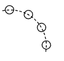
- the arrangement direction condition is a condition indicating in what direction the arrangement is projected in a certain arrangement.
- the parameter indicating the direction of the arcuate arrangement is the arrangement direction condition.
- the arrangement direction condition may be configured to be arbitrarily set, or may be configured to provide options (for example, upward, downward, leftward, rightward).
- the arrangement direction condition is used for controlling the galvano scanner 52.
- the spot size condition is a condition indicating at what size each spot is projected.
- a circular arrangement a circular arrangement with a different pattern can be applied by changing the projection size (diameter, area, circumference length, etc.) of each spot.
- the projection size for example, the area, circumference length, etc.
- the spot size can be individually set for each part.
- an optical member for changing the spot size is provided in the laser irradiation system 50.
- This optical member is, for example, a variable power lens (system).
- the processing unit 5 realizes the set spot size by moving the zoom lens along the optical axis (irradiation optical axis) 50 a of the laser irradiation system 50.
- the diameters of these light guides can be made different from each other.
- the spot size of the light irradiated to the eye E is changed by selectively using two or more light guide paths.
- the processing unit 5 arranges the galvanometer mirror 2c of the light source unit 2 in the direction in which the irradiation light is incident on the light guide path corresponding to the target spot size.
- the optical fiber 4 may be an imaging fiber (image transmission fiber) capable of transmitting light while holding a pattern.
- an optical member such as a variable magnification lens
- the control of this optical member is the same as when the optical fiber 4 consists of a single light guide.
- the light source unit 2 is provided with a galvano scanner for making the irradiation light of a predetermined pattern enter the optical fiber 4 (imaging fiber).
- This galvano scanner is provided instead of the galvano mirror 2c, for example. Further, it is not necessary to provide the galvano scanner 52 in the laser irradiation system 50.
- the spot interval condition is a condition indicating at what interval (pitch) the adjacent spots are projected.
- the spot interval condition may be configured to be arbitrarily set, or may be configured to provide options (for example, sparse or dense). Note that not all spot intervals need be the same in a certain array. In that case, it is possible to divide a certain array into a plurality of parts and to set the spot interval for each part individually.
- the spot interval condition is used for controlling the galvano scanner 52.
- Irradiation conditions include matters related to matters other than the pattern of irradiated light.
- the type of irradiation light can be included in the irradiation conditions.
- the type of irradiation condition there is a type of laser light (wavelength, application, etc.).
- Such irradiation light type conditions are used to control the aiming light source 2a and / or the therapeutic laser light source 2b.
- the irradiation condition may include a condition related to the intensity of irradiation light.
- the irradiation intensity condition there is an output intensity condition indicating the output intensity of irradiation light from the aiming light source 2a and the therapeutic laser light source 2b.
- the output intensity condition is used to control the aiming light source 2a and / or the therapeutic laser light source 2b.
- the output intensity condition may include a parameter indicating the energy of the therapeutic laser beam (laser beam) output from the therapeutic laser light source 2b.
- the irradiation intensity condition there is a condition (dimming condition) for adjusting the amount of irradiation light by the light reducing member.
- a neutral density filter as the neutral density member. More specifically, there are a configuration in which one neutral density filter is inserted into and removed from the optical path, and a configuration in which a plurality of neutral density filters having different transmittances can be selectively disposed in the optical path.
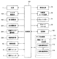
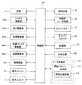
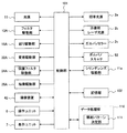
- Control system The control system of the laser treatment apparatus 1 will be described with reference to FIG.
- the control system of the laser treatment apparatus 1 is configured around a control unit 101 provided in the processing unit 5.
- FIG. 4 shows only components that are particularly focused on in this embodiment, and other components are omitted.
- Control unit 101 The control unit 101 controls each unit of the laser treatment apparatus 1. For example, the control unit 101 performs control of the light source unit 2, control of the display unit 7, control of the illumination system 10, control of the observation system 30, control of the laser irradiation system 50, and the like.
- control unit 101 performs control of the aiming light source 2a, control of the therapeutic laser light source 2b, control of the galvanometer mirror 2c, and the like.
- Control of the aiming light source 2a and the therapeutic laser light source 2b includes on / off of the output of the irradiation light, control of the output intensity (output light amount) of the irradiation light, and the like.
- the control unit 101 performs treatment so as to selectively output the treatment laser light LT.
- the laser light source 2b is controlled.
- Control of the galvanometer mirror 2c includes control for changing the direction of the reflecting surface of the galvanometer mirror 2c.
- the display unit 7 displays various information under the control of the control unit 101.
- the display unit 7 includes an arbitrary display device such as a flat panel display such as an LCD or a CRT display.
- the display unit 7 is provided, for example, in the slit lamp 3 or the processing unit 5 (computer).
- the control unit 101 performs GUI display control and operation control of each unit based on an operation on the GUI.
- control unit 101 performs control of the light source 11, control of the filters 13 to 15, control of the slit diaphragm 16, control of other diaphragm members, and the like.
- Control of the light source 11 includes ON / OFF of illumination light output, control of output intensity (output light amount) of illumination light, and the like.
- Control of the filters 13 to 15 includes control for inserting and removing the filters 13 to 15 independently from the illumination optical axis 10a.
- the filters 13 to 15 are controlled by controlling the filter driving unit 13A.
- the filter driving unit 13A includes an actuator such as a solenoid or a pulse motor, and a mechanism for transmitting the driving force generated by the actuator to the filters 13-15.
- Control of the slit diaphragm 16 includes control for changing the interval between the pair of slit blades, control for moving the pair of slit blades integrally, and the like.
- the former control corresponds to slit width change control.
- the latter control corresponds to control for changing the irradiation position of the illumination light (slit light) while keeping the slit width constant.
- other diaphragm members include an illumination diaphragm for changing the amount of illumination light and an illumination field diaphragm for changing the size of the illumination field.
- the slit diaphragm 16, the illumination diaphragm, and the illumination field diaphragm are controlled independently by controlling the diaphragm driver 16A.
- the aperture driving unit 16A includes an actuator such as a pulse motor and a mechanism for transmitting a driving force generated by the actuator to the aperture member.
- the control unit 101 performs control of the variable power lenses 32 and 33, control of the protection filter 34, control of the imaging lens 35, and the like.
- the zoom lenses 32 and 33 are controlled by controlling the zoom drive unit 32A to move them along the observation optical axis 30a. Thereby, the observation magnification (angle of view) is changed.
- the variable magnification drive unit 32A includes an actuator such as a pulse motor and a mechanism for transmitting a driving force generated by the actuator to the variable magnification lenses 32 and 33.
- the variable magnification drive unit 32A includes a mechanism for selectively inserting these variable magnification lens groups into the optical path of the observation system 30.
- the control unit 101 changes the observation magnification (view angle) by controlling the magnification driving unit 32A.
- the control of the protection filter 34 is to control the protection filter drive unit 34A to insert and remove the protection filter 34 with respect to the observation optical axis 30a.
- the imaging lens 35 is controlled by moving the imaging lens 35 along the observation optical axis 30a by controlling the imaging drive unit 35A. Thus, focusing of the observation image by the operator's eye E 0 is performed.
- the control unit 101 controls the photographing system.
- Control of the imaging system includes control of the imaging device 42.
- Control of the imaging device 42 includes control of the accumulation time of the image sensor, focus control by a built-in optical element, and the like.
- control of the variable power lenses 32 and 33 similarly to the control of the observation system 30 described above, control of the variable power lenses 32 and 33 (control for changing the photographing magnification and angle of view) and control of the imaging lens 35 (focusing) )and so on.
- the control unit 101 controls a mechanism for performing the operation.
- the control unit 101 controls the galvano scanner 52 and the like.
- the galvano scanner 52 includes a galvanometer mirror (first galvanometer mirror) for deflecting irradiation light in the left-right direction and a galvanometer mirror (second galvanometer mirror) for deflecting illumination light in the up-down direction.
- the control unit 101 independently changes the direction of the reflecting surface of the first galvanometer mirror and the direction of the reflecting surface of the second galvanometer mirror. Thereby, the irradiation light incident from the light source unit 2 through the optical fiber 4 can be deflected two-dimensionally.
- the control unit 101 performs a process of reading data stored in the storage unit 102 and a process of writing data to the storage unit 102.
- the control unit 101 includes a microprocessor, a RAM, a ROM, a hard disk drive, and the like. This hard disk drive stores a control program in advance. The operation of the control unit 101 is realized by the cooperation of this control program and the hardware.
- the control unit 101 may include a communication device for communicating with an external device. The control unit 101 is included in the “control unit”.
- the storage unit 102 stores various data and computer programs.
- the storage unit 102 includes a storage device such as a RAM, a ROM, and a hard disk drive.
- the storage unit 102 is included in the “control unit”.
- the operation unit 6 includes various hardware keys and / or software keys.
- the display unit 7 displays various information.
- the operation unit 6 is used for setting the irradiation condition of the irradiation light.
- the irradiation condition setting operation is performed using, for example, a predetermined hardware key or software key.
- Specific examples of the former include arbitrary conditions such as array conditions, array size conditions, array direction conditions, spot size conditions, spot interval conditions, spot number conditions, irradiation light type conditions, irradiation intensity conditions (output intensity conditions, dimming conditions), etc.
- a hardware key for setting irradiation conditions is provided in the operation unit 6 in advance. The user sets the irradiation condition by operating the hardware key corresponding to the desired irradiation condition. As a specific example of the latter, a setting screen for setting the irradiation conditions as described above is displayed on the display unit 7 by the control unit 101. The user sets the irradiation condition by operating the GUI provided on the displayed setting screen with the operation unit 6.
- the operation unit 6 is used to move the irradiation position of the irradiation light with respect to the fundus oculi Ef.
- the movement operation of the irradiation position is also performed using a predetermined hardware key or software key.
- the irradiation position is moved, for example, by the control unit 101 controlling the galvano scanner 52 or moving the optical system of the slit lamp 3.
- the slit lamp 3 is provided with a moving mechanism (optical system moving mechanism) for moving the optical system.
- the optical system moving mechanism is electrically controlled, and includes an actuator and a mechanism that transmits a driving force generated by the actuator.
- it is also possible to move the optical system by moving the optical system of the slit lamp 3 using the operation performed by the user as a driving force.
- FIG. 4 shows the operation unit 6 and the display unit 7 separately, but they can also be configured integrally.
- a touch panel LCD can be used.
- the data processing unit 110 performs various data processing.
- the data processing unit 110 is provided with an irradiation pattern determination unit 111.
- the irradiation pattern determination unit 111 performs treatment based on a captured image acquired by imaging the eye E to be examined in a state where the aiming light LA of a predetermined pattern is irradiated and a predetermined pattern of the aiming light LA.
- the irradiation pattern of the laser beam LT for use is determined. That is, the irradiation pattern determination unit 111 performs laser treatment that is continuously performed based on the pattern of the aiming light LA irradiated to the eye E and the pattern of the aiming light LA that is actually depicted in the captured image.
- the irradiation pattern of the therapeutic laser beam LT to be used is determined.
- the captured image may be a front image (fundus image) of the fundus oculi Ef or a front image (anterior eye image) of the anterior segment.
- the irradiation pattern determination unit 111 includes a projection image specifying unit 112.
- the projection image specifying unit 112 analyzes the captured image acquired by capturing the eye E with the predetermined pattern of the aiming light LA being irradiated by the imaging system, thereby projecting the aiming light LA in the captured image. Identify the image.
- the projected image of the aiming light LA is a spot image (bright spot image) obtained by detecting the reflected light of the aiming light LA.
- the projection image specifying unit 112 can specify the projection image by analyzing pixel information of the captured image, for example.
- the pixel information is information relating to a plurality of pixels constituting the captured image, and includes pixel position information and pixel value information for each pixel.
- the projection image specifying unit 112 specifies the projection image by analyzing pixel position information and pixel value information.
- the projection image specifying unit 112 refers to the pixel value information to project the projection image Can be specified.
- the projection image based on the shape and size of each projection image.
- the projected image can be specified by specifying a substantially circular image region in the captured image.
- image regions having substantially the same shape and size may be selected so that a portion of the fundus oculi Ef (optic nerve head, etc.) and a lesioned part are not erroneously extracted.
- FIGS. 5A and 5B Examples of projected images of the aiming light LA are shown in FIGS. 5A and 5B.
- the photographed images shown in these drawings are fundus images.
- the imaging range of the fundus oculi Ef is limited by the iris of the eye E to be examined.
- the irradiation area of the aiming light LA is also limited by the iris.
- a part of the aiming light LA may be blocked by the iris. .
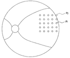
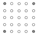
- FIG. 5A shows an example of a fundus image obtained when the aiming light LA having the rectangular plate-like arrangement (lattice arrangement) shown in FIG. 3H is applied and any aiming light LA is not obstructed by the iris. .
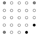
- FIG. 5B shows an example of a fundus image obtained when a part of the aiming light LA is blocked by the iris when the aiming light LA having the same rectangular plate array (lattice array) is applied.
- the projection image Pj located at the upper right of the N projection images Pi arranged in a grid pattern is not drawn. This is because the aiming light LA corresponding to the projection image Pj is blocked by the iris. Therefore, when laser treatment of the same arrangement is performed in this state, the treatment laser light LT is irradiated at substantially the same position as the position shown in the projection image Pi (i ⁇ j), but the projection image Pj The therapeutic laser beam LT to be irradiated to the position shown in FIG.
- the captured image is a fundus image
- the captured image is an anterior segment image
- the following is performed.
- a projected image of the aiming light LA is depicted on the anterior eye image
- this projected image corresponds to the aiming light LA irradiated on the iris.
- the projected image drawn in the anterior segment image corresponds to an irradiation position (projected image) that is not drawn in the fundus image. That is, assuming that the array of the aiming light LA irradiated to the eye E is an entire set, the projection image in the fundus image and the projection image in the anterior segment image are complementary to each other.
- the processing described below relates to the fundus image, but considering this complementary relationship, the same processing can be executed even when the anterior ocular segment image is used.
- the irradiation pattern determination unit 111 determines the irradiation pattern based on the projection image specified by the projection image specification unit 112 and the pattern of the aiming light LA that was emitted when the captured image was obtained. In order to execute a specific example of this processing, a difference specifying unit 113 is provided in the irradiation pattern determining unit 111 of this embodiment.
- the difference specifying unit 113 specifies a difference between the array indicated by the pattern of the aiming light LA irradiated to the eye E when acquiring the captured image and the array of the projection images specified by the projection image specifying unit 112. To do. An example of this processing will be described below.
- the pattern of the aiming light LA is set in advance as described above.
- Information pattern setting information indicating the setting contents (especially arrangement conditions) is stored in the storage unit 102 by the control unit 101.
- the control unit 101 reads the pattern setting information from the storage unit 102 and sends it to the difference specifying unit 113.
- the difference specifying unit 113 generates information (projection image arrangement information) indicating the arrangement of the projection images based on the projection image specified by the projection image specifying unit 112.
- the pattern setting information and the projection image array information are information in arbitrary forms.
- these pieces of information may each be a graph including a set of nodes (vertices) indicating the irradiation position of each aiming light LA and a set of edges (sides) connecting the nodes.
- the difference specifying unit 113 obtains a difference between the arrangement indicated by the pattern of the aiming light LA and the arrangement of the projection images, for example, by comparing graphs indicated by both pieces of information.
- an image (array image) showing the array of the irradiation positions of the aiming light LA can be used.
- the difference specifying unit 113 specifies a rotation position with a high degree of coincidence between the images by relatively rotating both array images as necessary. To do.
- the difference specifying unit 113 specifies a difference between two substantially matched array images, that is, an irradiation position that exists in one (pattern setting information) but does not exist in the other (projected image array information).
- the difference specifying unit 113 obtains a difference between the array indicated by the pattern of the aiming light LA and the array of the projected images.
- the alignment of the aiming light LA irradiated to the eye E is a lattice-like array in the rectangular region shown in FIG. The difference between these is none.
- the array of the aiming light LA irradiated to the eye E is a similar lattice array, but the array of the projected images is obtained from the lattice array by using the projected image Pj. Since the arrangement is excluded, these differences are portions corresponding to the projection image Pj.
- the irradiation pattern determining unit 111 excludes at least a portion corresponding to the difference specified by the difference specifying unit 113 from the pattern of the aiming light LA irradiated to the eye E to thereby determine the irradiation pattern of the therapeutic laser beam LT.
- the irradiation pattern determination unit 111 can exclude only the part corresponding to the difference, and can also exclude the part other than the difference. Also, one of these processing modes may be always performed, or these processing modes may be selectively performed. As an example of performing the process of excluding a part other than the difference, an irradiation position in the vicinity of the part corresponding to the difference (for example, an irradiation position adjacent to the part corresponding to the difference) can be excluded. .
- the irradiation position below predetermined distance with respect to the outer periphery (contour) of a picked-up image may be excluded.
- the captured image can be displayed on the display unit 7 so that the user can select an exclusion target using the operation unit 6. At this time, it is possible to evaluate the possibility of each irradiation position (projection image) being vignetted by the iris based on the distance to the outer edge of the photographed image and present the evaluation result (for example, evaluation of the display mode of the projection image) Depending on the outcome).
- Information indicating the irradiation pattern determined by the irradiation pattern determination unit 111 is sent to the control unit 101.
- the control unit 101 controls the light source unit 2 and the laser irradiation system 50 based on the irradiation pattern information. Thereby, laser treatment with the determined irradiation pattern is performed. For example, when the captured image shown in FIG. 5A is obtained, the therapeutic laser beam LT is irradiated to each of a plurality of irradiation positions arranged in a grid pattern shown in FIG. 3H. On the other hand, when the captured image shown in FIG.
- the treatment laser beam LT is irradiated respectively.
- the galvano scanner 52 is controlled.
- the galvano scanner 52 is an example of a scanning unit that changes the irradiation position of the therapeutic laser beam LT on the fundus oculi Ef.
- the control unit 101 controls the galvano scanner 52 based on the irradiation pattern determined by the irradiation pattern determination unit 111. More specifically, the control unit 101 controls the galvano scanner 52 so as to sequentially irradiate the therapeutic laser beam LT to one or more irradiation positions included in the determined irradiation pattern.
- the second example is applied when the optical fiber 4 is an imaging fiber.
- a galvano scanner is provided in front of the imaging fiber.
- the control unit 101 controls the galvano scanner based on the irradiation pattern determined by the irradiation pattern determination unit 111, thereby causing the therapeutic laser light LT having the irradiation pattern to enter the imaging fiber.
- the irradiation position corresponding to the difference between the pattern of the aiming light LA (aiming pattern) and the pattern determined by the irradiation pattern determination unit 111 is “empty shot”.
- This process is performed by controlling the galvano scanner 52 and the galvanometer mirror 2c.
- the galvano scanner 52 is an example of a scanning unit that changes the irradiation position of the therapeutic laser beam LT on the fundus oculi Ef.
- the galvanometer mirror 2c includes a path switching unit for switching the path of the therapeutic laser light LT to a path (first path) toward the eye E and a path (second path) toward the light-shielding plate 2d. It is an example of 1 reflection member.
- the control unit 101 controls the galvano scanner 52 based on the aiming pattern, and synchronizes with the control of the galvano scanner 52 corresponding to the portion excluded from the aiming pattern to set the path of the treatment laser light LT to the second path.
- the galvanometer mirror 2c is controlled to switch to That is, the control unit 101 directs the galvano mirror 2c in the direction corresponding to the first path at the timing of directing the galvano scanner 52 in the direction corresponding to the irradiation position included in the pattern determined by the irradiation pattern determination unit 111. At the timing when the galvano scanner 52 is directed in the direction corresponding to the excluded irradiation position, the galvano mirror 2c is directed in the direction corresponding to the second path.
- the control unit 101 turns on the light source 11 of the illumination system 10. Thereby, the fundus oculi Ef is illuminated by the illumination light.
- This illumination light is assumed to be stationary light.
- the user sets irradiation conditions (particularly arrangement conditions) of the aiming light LA. This setting operation is performed using the operation unit 6.
- a signal indicating the setting content of the irradiation condition is sent to the control unit 101.
- the control unit 101 causes the storage unit 102 to store information indicating the setting contents of irradiation conditions (particularly, arrangement conditions).
- the control unit 101 controls the aiming light source 2a, the galvano mirror 2c, the galvano scanner 52, and the like so that the aiming light LA having the pattern set in step 2 is displayed on the fundus oculi Ef. To irradiate.
- a photographed image of the fundus oculi Ef is acquired using the imaging device 42.
- This process is performed as follows, for example.
- moving image shooting by the imaging device 42 is started simultaneously with the start of illumination light (stationary light) irradiation in Step 1, and a frame obtained at a timing when the user performs a predetermined shooting operation is acquired as a shot image. can do.
- the control unit 101 controls the imaging device 42 to perform still image photographing of the fundus oculi Ef, and the still image obtained thereby is used as a photographed image.
- the shooting light source is turned on (flash emission or continuous emission may be performed), and a captured image is acquired by controlling the imaging device 42. Can do.
- the control unit 101 sends the captured image (image data thereof) to the projection image specifying unit 112.
- the projection image specifying unit 112 analyzes the captured image to specify the projection image of the aiming light LA in the captured image.
- the projection image identification result is sent to the difference identification unit 113.
- the difference specifying unit 113 receives the projection image specifying result in step 6 and the irradiation condition set in step 2 (particularly the arrangement condition, that is, the aiming pattern). The difference specifying unit 113 specifies the difference between the aiming pattern and the arrangement of the projected images.
- the irradiation pattern determination unit 111 determines the irradiation pattern of the therapeutic laser beam LT based on the difference specified in Step 7. Irradiation pattern information indicating the determined irradiation pattern is sent to the control unit 101.
- the control unit 101 stops the irradiation of the aiming light LA to the eye E and controls the treatment laser light source 2b, the galvano mirror 2c, the galvano scanner 52, and the like in step 8.
- the treatment laser beam LT having the determined pattern is irradiated onto the fundus oculi Ef.
- Laser treatment apparatus 1 has an imaging system (observation system 30), an irradiation system (light source unit 2 and laser irradiation system 50), irradiation pattern determination unit 111, and control unit 101.
- the imaging system images the eye E.
- the irradiation system irradiates the sighting light LA having a predetermined pattern (sighting pattern) and the treatment laser light LT toward the fundus oculi Ef of the eye E to be examined.
- the irradiation pattern determination unit 111 determines the irradiation pattern of the therapeutic laser beam LT based on the captured image of the eye E to be examined captured by the imaging system and the aiming pattern.
- the control unit 101 controls the irradiation system to irradiate the therapeutic laser beam LT with the determined irradiation pattern.
- the irradiation pattern determination unit 111 is based on the photographed image and the aiming pattern, The irradiation pattern of the therapeutic laser beam LT can be determined.
- the irradiation pattern determination unit 111 may include a projection image identification unit 112 that identifies a projection image of the aiming light LA in the captured image by analyzing the captured image. Furthermore, the irradiation pattern determination unit 111 can determine the irradiation pattern of the therapeutic laser beam LT based on the specified projection image and aiming pattern.
- the irradiation pattern determination unit 111 may include a difference specifying unit 113 that specifies a difference between the arrangement indicated by the aiming pattern and the arrangement of the projection images specified by the projection image specifying unit 112. Furthermore, the irradiation pattern determination unit 111 can determine the irradiation pattern of the therapeutic laser beam LT by excluding at least a portion corresponding to the difference from the aiming pattern.
- the irradiation system may include a scanning unit (galvano scanner 52) that changes the irradiation position of the therapeutic laser beam LT on the fundus oculi Ef.
- the control unit 101 can control the scanning unit based on the irradiation pattern determined by the irradiation pattern determination unit 111.
- the irradiation system may include a scanning unit and a path switching unit.
- the scanning unit (galvano scanner 52) changes the irradiation position of the therapeutic laser beam LT on the fundus oculi Ef.
- the path switching unit (galvanomirror 2c) switches the path of the treatment laser light LT between a first path toward the eye E and a second path not toward the eye E.
- the control unit 101 controls the scanning unit based on the predetermined pattern, and switches the path of the treatment laser light LT to the second path in synchronization with the control of the scanning unit corresponding to the portion excluded from the predetermined pattern.
- the path switching unit can be controlled.
- the path switching unit may include a first reflecting member (galvanomirror 2c) that is provided in the path of the therapeutic laser beam LT and can change the direction of the reflecting surface that reflects the therapeutic laser beam LT.
- the control unit 101 can switch the path of the therapeutic laser beam LT by changing the direction of the reflecting surface of the first reflecting member.
- the irradiation pattern of the treatment laser light LT can be determined based on the captured image and the aiming pattern. Therefore, it is possible to irradiate the therapeutic laser beam LT by excluding the irradiation position that may be irradiated to the iris. Therefore, it is possible to improve the safety of ophthalmic laser treatment.
- the laser treatment apparatus of this embodiment has the same overall configuration as that of the first embodiment (see FIG. 1) and the configuration of the optical system (FIGS. 1 and 2). Further, this laser treatment apparatus irradiates the eye to be examined with the irradiation light having the same pattern as that of the first embodiment (see FIGS. 3A to 3L).
- a configuration example of a control system of this laser treatment apparatus is shown in FIG. Note that the difference between the control system of this embodiment and the control system of the first embodiment is substantially only the configuration of the irradiation pattern determination unit 111.
- description will be made by applying the reference numerals used in the first embodiment.
- the captured image of this embodiment is an image of the fundus oculi Ef.
- the irradiation pattern determination unit 111 of this embodiment includes a projection image specifying unit 112.
- the projection image specifying unit 112 performs the same processing as in the first embodiment. Further, the irradiation pattern determination unit 111 determines the irradiation pattern of the therapeutic laser beam LT by excluding at least a part of the projection image based on the pixel information corresponding to the projection image specified by the projection image specifying unit 112. I do.
- the irradiation pattern determination unit 111 includes a projection image selection unit 114.
- the projection image selection unit 114 is configured to execute one or more of the three processes described below.
- the projection image selection unit 114 selects a projection image having a relatively low brightness among the projection images specified by the projection image specification unit 112. More specifically, the projection image selection unit 114 obtains a value (corresponding value) corresponding to the projection image based on the pixel value (luminance value) of the pixel corresponding to each projection image.
- This corresponding value is, for example, a statistical value obtained by statistically processing the luminance values of a plurality of pixels corresponding to the projected image.
- the statistical values include an average value, a median value, a mode value, a maximum value, a minimum value, and a sum. Thereby, the corresponding values of the plurality of projection images are obtained.
- the projection image selection unit 114 specifies a relatively small corresponding value among the plurality of corresponding values. Thereby, a relatively low-brightness projection image is selected. This selection is performed by an arbitrary process. For example, an average value of a plurality of corresponding values can be calculated, and a corresponding value that is smaller than the average value by a predetermined value or more can be selected. Moreover, you may make it select the corresponding value below a predetermined value among several corresponding values.
- the projection image selection unit 114 that performs the processing as described above is an example of a first selection unit.
- the irradiation pattern determination unit 111 excludes at least a portion corresponding to the relatively low-brightness projection image selected by the projection image selection unit 114 from the pattern of the aiming light LA (aiming pattern), so that the therapeutic laser beam is used.
- the irradiation pattern of LT is determined.
- the portion is determined in the same manner as in the first embodiment.
- the projection image selection unit 114 selects a projection image having a relatively large size from among the projection images specified by the projection image specification unit 112. More specifically, the projection image selection unit 114 determines the size of the projection image based on pixel information corresponding to each projection image.
- the size of the projection image is determined by an arbitrary process. For example, the number of pixels corresponding to the projected image can be counted, and this number (number of pixels) can be used as size information of the projected image. Further, size information such as the diameter and perimeter of the projected image may be calculated based on pixel position information of the pixel corresponding to the projected image.
- the projection image selection unit 114 selects relatively large value size information from the plurality of size information obtained as described above. This selection is performed by an arbitrary process. For example, an average value of a plurality of size information can be calculated, and size information larger than this average value by a predetermined value or more can be selected. Moreover, you may make it select the size information more than a predetermined value among several size information.
- the projection image selection unit 114 that performs the processing as described above is an example of a second selection unit.
- the irradiation pattern determination unit 111 excludes at least a portion corresponding to the projection image having a relatively large size selected by the projection image selection unit 114 from the pattern of the aiming light LA (aiming pattern).
- the irradiation pattern of LT is determined.
- the projection image selection unit 114 selects a projection image having a different shape from the projection images specified by the projection image specification unit 112.
- the projected image of the aiming light LA irradiated on the fundus oculi Ef without being blocked by the iris has, for example, a substantially circular outline.
- the projected image of the aiming light LA partially blocked by the iris has an outline with a shape that is partially cut out of a substantially circular shape.
- the projection image selection unit 114 for example, based on the pixel position information (and pixel value information) of the pixel corresponding to each projection image, the contour of the projection image Is identified.
- the projection image selection unit 114 selects a projection image having a different contour shape from among the plurality of projection images.
- a projection image having a contour shape different from the contour shape may be selected. Good.
- the irradiation pattern determination unit 111 determines the irradiation pattern of the therapeutic laser beam LT by excluding at least a portion corresponding to the projection image selected by the projection image selection unit 114 from the pattern of the aiming light LA (aiming pattern). To do.
- the user sets irradiation conditions (particularly arrangement conditions) of the aiming light LA. This setting operation is performed using the operation unit 6.
- a signal indicating the setting content of the irradiation condition is sent to the control unit 101.
- the control unit 101 causes the storage unit 102 to store information indicating the setting contents of irradiation conditions (particularly, arrangement conditions).
- the control unit 101 controls the aiming light source 2a, the galvano mirror 2c, the galvano scanner 52, and the like, so that the aiming light LA having the pattern set in step 22 is displayed on the fundus oculi Ef. To irradiate.
- the control unit 101 sends the captured image (image data thereof) to the projection image specifying unit 112.
- the projection image specifying unit 112 analyzes the captured image to specify the projection image of the aiming light LA in the captured image.
- the projection image identification result is sent to the difference identification unit 113.
- the projection image selection unit 114 selects a characteristic projection image from among the projection images specified in step 26.
- the characteristic projected image is, for example, a relatively low-luminance projected image, a relatively large projected image, or a projected image having a different shape.
- the irradiation pattern determination unit 111 determines the irradiation pattern of the therapeutic laser beam LT by excluding at least a portion corresponding to the projection image selected in step 27 from the aiming pattern. Irradiation pattern information indicating the determined irradiation pattern is sent to the control unit 101.
- the control unit 101 stops the irradiation of the aiming light LA with respect to the eye E and controls the treatment laser light source 2b, the galvano mirror 2c, the galvano scanner 52, and the like in step 28.
- the treatment laser beam LT having the determined pattern is irradiated onto the fundus oculi Ef.
- the irradiation control of the therapeutic laser beam LT is executed, for example, in the same manner as in the first embodiment.
- Laser treatment apparatus 1 has an imaging system (observation system 30), an irradiation system (light source unit 2 and laser irradiation system 50), irradiation pattern determination unit 111, and control unit 101.
- the imaging system images the eye E.
- the irradiation system irradiates the sighting light LA having a predetermined pattern (sighting pattern) and the treatment laser light LT toward the fundus oculi Ef of the eye E to be examined.
- the irradiation pattern determination unit 111 determines the irradiation pattern of the therapeutic laser beam LT based on the captured image of the eye E to be examined captured by the imaging system and the aiming pattern.
- the control unit 101 controls the irradiation system to irradiate the therapeutic laser beam LT with the determined irradiation pattern.
- the irradiation pattern determination unit 111 is based on the photographed image and the aiming pattern, The irradiation pattern of the therapeutic laser beam LT can be determined.
- the irradiation pattern determination unit 111 may include a projection image identification unit 112 that identifies a projection image of the aiming light LA in the captured image by analyzing the captured image. Furthermore, the irradiation pattern determination unit 111 can determine the irradiation pattern of the therapeutic laser beam LT based on the specified projection image and aiming pattern.
- the irradiation pattern determination unit 111 determines the irradiation pattern of the therapeutic laser beam LT by excluding at least a part of the projection image based on pixel information corresponding to the projection image specified by the projection image specifying unit 112. be able to.
- the irradiation pattern determination unit 111 may include a first selection unit (projection image selection unit 114) that selects a relatively low-brightness projection image among the projection images identified by the projection image identification unit 112. Furthermore, the irradiation pattern determination unit 111 can determine the irradiation pattern of the therapeutic laser beam LT by excluding at least a portion corresponding to the selected projection image from the aiming pattern. Thereby, for example, the irradiation position of the aiming light LA that is partially blocked by the iris and darkened the projected image can be excluded and the therapeutic laser beam LT can be irradiated.
- the irradiation pattern determination unit 111 may include a second selection unit (projection image selection unit 114) that selects a projection image having a relatively large size among the projection images identified by the projection image identification unit 112. Furthermore, the irradiation pattern determination unit 111 can determine the irradiation pattern of the therapeutic laser beam LT by excluding at least a portion corresponding to the selected projection image from the aiming pattern. Thereby, for example, the irradiation of the aiming light LA in which the size of the projection image is increased due to the blur generated by the aberration of the apparatus optical system or the eyeball optical system affecting the aiming light LA toward the peripheral portion of the fundus oculi Ef The therapeutic laser beam LT can be irradiated without the position.
- the irradiation pattern determination unit 111 may include a third selection unit (projection image selection unit 114) that selects a projection image having a different shape from the projection images identified by the projection image identification unit 112.
- the irradiation pattern determination unit 111 can determine the irradiation pattern of the therapeutic laser beam LT by excluding at least a portion corresponding to the selected projection image from the aiming pattern. Thereby, for example, the irradiation position of the aiming light LA that is partially blocked by the iris and has changed the shape of the projection image can be excluded, and the therapeutic laser beam LT can be irradiated.
- the irradiation system may include a scanning unit (galvano scanner 52) that changes the irradiation position of the therapeutic laser beam LT on the fundus oculi Ef.
- the control unit 101 can control the scanning unit based on the irradiation pattern determined by the irradiation pattern determination unit 111.
- the irradiation system may include a scanning unit and a path switching unit.
- the scanning unit (galvano scanner 52) changes the irradiation position of the therapeutic laser beam LT on the fundus oculi Ef.
- the path switching unit (galvanomirror 2c) switches the path of the treatment laser light LT between a first path toward the eye E and a second path not toward the eye E.
- the control unit 101 controls the scanning unit based on the predetermined pattern, and switches the path of the treatment laser light LT to the second path in synchronization with the control of the scanning unit corresponding to the portion excluded from the predetermined pattern.
- the path switching unit can be controlled.
- the path switching unit may include a first reflecting member (galvanomirror 2c) that is provided in the path of the therapeutic laser beam LT and can change the direction of the reflecting surface that reflects the therapeutic laser beam LT.
- the control unit 101 can switch the path of the therapeutic laser beam LT by changing the direction of the reflecting surface of the first reflecting member.
- the irradiation pattern of the therapeutic laser beam LT can be determined based on the captured image and the aiming pattern. Therefore, it is possible to irradiate the therapeutic laser beam LT by excluding the irradiation position that may be irradiated to the iris. Therefore, it is possible to improve the safety of ophthalmic laser treatment.
- laser treatment can be performed by removing the aiming light LA in which the projection image becomes large or dark. Therefore, it is possible to prevent the effect of ophthalmic laser treatment from being reduced.
- the laser treatment apparatus of this embodiment has the same overall configuration as that of the first embodiment (see FIG. 1) and the configuration of the optical system (FIGS. 1 and 2). Further, this laser treatment apparatus irradiates the eye to be examined with the irradiation light having the same pattern as that of the first embodiment (see FIGS. 3A to 3L).
- a configuration example of the control system of this laser treatment apparatus is shown in FIG. Note that the difference between the control system of this embodiment and the control system of the first embodiment is substantially only the configuration of the irradiation pattern determination unit 111.
- description will be made by applying the reference numerals used in the first embodiment.
- the imaging system of the laser treatment apparatus of this embodiment acquires a photographed image by photographing the eye E with the contact lens CL for laser treatment being in contact therewith. This photographed image is focused on at least the contact lens CL.
- the irradiation pattern determination unit 111 determines the irradiation pattern of the therapeutic laser beam LT based on this captured image and a preset aiming pattern. At this time, the irradiation pattern determination unit 111 can determine the irradiation pattern of the therapeutic laser beam LT by excluding a part of the aiming pattern based on the captured image and the aiming pattern. An example of this processing will be described below.
- the aberration information 102a is stored in the storage unit 102 in advance.
- the aberration information 102a includes contact lens aberration information and / or eyeball aberration information.
- the contact lens aberration information is information indicating each aberration of one or more contact lenses CL applied (selectively) to the eye E, and is an example of first aberration information.
- the contact lens aberration information is, for example, information indicating the amount of aberration in each part of the contact lens CL, that is, information indicating the distribution of the amount of aberration.
- the ocular aberration information is information indicating the standard value of the aberration of the human eye or the actually measured value of the aberration of the eye E, and is an example of second aberration information.
- the standard value of the human eye aberration is, for example, information (average value or the like) obtained by statistically processing information obtained by measuring the aberration of many human eyes.
- aberration information such as a model eye may be used.
- the actual measurement value of the aberration of the eye E can be applied when the aberration measurement of the eye E is performed in advance.
- the ocular aberration information is, for example, information indicating the aberration amount in each part of the standard human eye or the eye E, that is, information indicating the distribution of the aberration amount.
- the irradiation pattern determining unit 111 includes a marker image specifying unit 115, a relative position information acquiring unit 116, and an aberration amount acquiring unit 117.
- the contact lens CL of this embodiment is provided with one or more markers.
- the marker is provided, for example, at a position on the imaging system side of the contact lens CL that is in contact with the eye E. That is, the marker is provided in the contact lens CL at a position that is reflected in a captured image acquired by the imaging system.
- the marker is provided, for example, in a form having a reflectance different from that of at least the vicinity region of the installation position.
- the marker is made of a material having a higher reflectance than a material constituting the contact lens CL and a material for coating the material. Further, the marker need not be provided on the contact lens CL itself, and may be provided on the attachment of the contact lens CL.
- a light source for illuminating the marker can be provided depending on the position where the marker is provided.
- This marker illumination light source is provided, for example, at a position off the optical path of the apparatus optical system (such as a position outside the objective lens 31).
- the marker image specifying unit 115 analyzes the photographed image obtained by photographing the eye E in a state where the contact lens CL to which the marker is attached is in contact, and thereby the marker image (marker in this photographed image). Image). This processing is performed, for example, by image processing based on the pixel value (luminance value or the like) of the captured image.
- the relative position information acquisition unit 116 acquires relative position information indicating the relative position between the laser irradiation system 50 and the contact lens CL based on the captured image.
- This relative position indicates the position of the optical axis (for example, the central axis) of the contact lens CL with respect to the optical axis of the laser irradiation system 50, for example.
- the relative position between the laser irradiation system 50 and the contact lens CL may be expressed with the optical axis of the objective lens 31 as a reference.
- the position (eccentric position) of the optical axis of the laser irradiation system 50 and the position (eccentric position) of the optical axis (center axis, etc.) of the contact lens CL are represented. These eccentric positions can be set as relative positions.
- the relative position information acquisition unit 116 can acquire the relative position information based on the marker image specified by the marker image specifying unit 115.
- the relative position information can be obtained based on the position of the marker image in the captured image, and the relative position information can be obtained based on the shape of the marker image.
- An example of the relative position information acquisition process based on the marker image will be described below.
- the number of markers provided on the contact lens CL is an arbitrary number of 1 or more.
- Some contact lenses CL have directionality, such as a trihedral mirror, that is, those that are not rotationally symmetric.
- one marker is provided at a position indicating a predetermined direction. Then, photographing is performed in a state where the contact lens CL is in contact with the eye E.
- the marker image specifying unit 115 specifies a marker image in the acquired captured image.
- the relative position information acquisition unit 116 obtains the position of the marker image in this captured image.
- the position of the marker image is, for example, the position of the marker image with respect to a predetermined position of the captured image.
- This predetermined position is obtained, for example, as position information with respect to a predetermined position (for example, the frame center) in the frame of the captured image.
- the predetermined position is obtained as position information with respect to a characteristic part (for example, the center position of the contact lens CL) depicted in the captured image. This characteristic part is specified by arbitrary image processing.
- the relative position information acquisition unit 116 obtains the position of the marker image with respect to a predetermined position of the captured image.
- a relative position between the marker image and the laser irradiation system 50 that is, a relative position between the contact lens CL and the laser irradiation system 50 is obtained.
- This relative position becomes relative position information.
- the deflection member 58 can be configured to be movable.
- the relative position information acquisition unit 116 is based on the shape of the marker image in the photographed image obtained by photographing the contact lens CL to which the marker is attached, that is, based on the distortion of the shape of the marker image with respect to the shape of the marker.
- the inclination of the contact lens CL can be acquired. This inclination is expressed as an inclination with respect to the optical axis of the laser irradiation system 50 or the optical axis of the objective lens 31, for example.
- a circular marker is provided on the contact lens CL.
- the relative position information acquisition unit 116 obtains the contour shape of the marker image specified from the captured image.
- the marker image is considered to have an elliptical shape corresponding to the inclination of the contact lens CL. That is, the shape of the marker image is considered to have an elliptical shape in which the inclination direction of the contact lens CL is the minor axis direction and has an ellipticity (ratio between the minor axis and the major axis) according to the inclination angle. Therefore, the relative position information acquisition unit 116 can obtain information indicating the tilt state of the contact lens CL based on the elliptical shape of the marker image. This information becomes relative position information.
- the relative position information acquisition unit 116 specifies the form of each marker image and obtains the relative position information based on the identification result. be able to. For example, as in the case of one marker, the relative position information can be obtained based on the position and shape of a marker image in a predetermined form in the captured image.
- relative position information can be obtained based on the relative positions of the plurality of marker images.
- markers M1 to M4 are provided on the surface of the contact lens CL on the objective lens 31 side.
- markers M1 to M4 are provided in the frame portion of the contact lens CL.
- the markers M1 and M3 are arranged at the opposing positions, and the markers M2 and M4 are arranged at the opposing positions. Further, it is assumed that the distance between the markers M1 and M3 is equal to the distance between the markers M2 and M4.
- the line segment connecting the markers M1 and M3 and the line segment connecting the markers M2 and M4 are orthogonal to each other.
- the relative position information acquisition unit 116 can acquire relative position information indicating the tilt state of the contact lens CL based on the relative positions of these four marker images.
- the relative position information can be acquired based on the photographed image.
- relative position information can be acquired based on the shape of the contact lens CL or the attachment.
- one or more feature parts are provided on the contact lens CL or the like, and the relative position information is acquired based on the position, orientation, or shape of the feature part image in the captured image, or the positional relationship of the plurality of feature parts. be able to.
- Such a characteristic part is assumed to be included in the “marker”.
- the contact lens CL is irradiated with a parallel light beam.
- the parallel light flux include irradiation light (aiming light) from the laser irradiation system 50, illumination light from the illumination system 10, and light irradiated by another optical system (light source).
- the contact lens CL is irradiated with a parallel light beam.
- the imaging surface of the imaging element of the imaging device 42 is arranged at a position conjugate with a position corresponding to 1 ⁇ 2 of the radius of curvature r of the surface of the contact lens CL.
- a reflected image of the parallel luminous flux by the contact lens CL is drawn on the photographed image obtained by such photographing.
- the relative position information acquisition unit 116 is information indicating the eccentric state of the contact lens CL with respect to the optical axis of the objective lens 31 or the optical axis of the laser irradiation system 50 (eccentricity). Direction and amount of eccentricity). Even when information indicating the eccentric state with respect to the objective lens 31 is obtained, it is assumed that the positional relationship between the optical axis of the objective lens 31 and the optical axis of the laser irradiation system 50 is known as described above. By doing so, it is possible to acquire relative position information indicating the eccentric state of the contact lens CL with respect to the optical axis of the laser irradiation system 50.
- the aberration amount acquisition unit 117 acquires the amount of aberration given to the aiming light LA included in the aiming pattern based on the relative position information acquired by the relative position information acquisition unit 116 and the aiming pattern. For example, this processing may be performed for all the aiming lights LA included in the aiming pattern, or may be performed only for a part of the aiming lights LA. In the latter case, for example, the aiming light LA assumed to have a large aberration amount is selected based on the aiming pattern and the relative position information, and the aberration amount is acquired only for the selected aiming light LA.
- the aberration amount acquisition unit 117 can obtain the amount of aberration given to the aiming light LA by referring to the aberration information 102a stored in the storage unit 102. For example, when the contact lens aberration information is included in the aberration information 102a, the aberration amount acquisition unit 117 first determines the aiming light LA included in the aiming pattern with respect to the contact lens CL based on the relative position information and the aiming pattern. Find the incident position. Then, the aberration amount acquisition unit 117 calculates the amount of aberration given to the aiming light LA for each aiming light LA whose incident position has been determined based on the incident position and contact lens aberration information.
- This process is performed, for example, by specifying the aberration amount at the incident position of the aiming light LA from the aberration amount distribution information indicated in the contact lens aberration information. Thereby, the amount of aberration given by the contact lens CL to the aiming light LA is obtained.
- the aberration information 102a includes eyeball aberration information
- the amount of aberration given by the eyeball optical system to the aiming light LA is obtained based on the incident position of the aiming light LA and the eyeball aberration information. be able to.
- the aberration amount obtained by referring to the contact lens aberration information as described above and the eyeball aberration information are obtained.
- the aberration information it is possible to determine the amount of aberration given to the aiming light LA by the contact lens CL and the eyeball optical system.
- the irradiation pattern determination unit 111 determines the irradiation pattern of the therapeutic laser beam LT based on the aberration amount acquired by the aberration amount acquisition unit 117. As an example of this process, the irradiation pattern determination unit 111 determines the irradiation pattern of the therapeutic laser beam LT by excluding a part of the pattern of the aiming light LA (aiming pattern) based on the acquired amount of aberration. can do. As the exclusion process, for example, a process of excluding the aiming light LA whose aberration amount is larger than a predetermined threshold or a process of excluding the aiming light LA having a relatively large aberration amount among all the acquired aberration amounts. Done.
- warning processing is performed, for example, by causing the display unit 7 to display predetermined warning information (visual information) by the control unit 101. Further, the control unit 101 may control a voice output unit (not shown) to output predetermined warning information (voice information). Further, a warning process may be performed together with the irradiation pattern determination process, or these processes may be performed separately. As an example of the latter, first, warning processing is performed, and irradiation pattern determination processing can be performed in response to an instruction from a user who has received warning information.
- the user sets irradiation conditions (particularly arrangement conditions) of the aiming light LA. This setting operation is performed using the operation unit 6.
- a signal indicating the setting content of the irradiation condition is sent to the control unit 101.
- the control unit 101 causes the storage unit 102 to store information indicating the setting contents of irradiation conditions (particularly, arrangement conditions).
- the irradiation of the aiming light LA of the pattern set in step 42 and the aiming may be performed.
- the control unit 101 sends the captured image (image data thereof) to the marker image specifying unit 115.
- the marker image identification unit 115 identifies the marker image in the captured image by analyzing the captured image.
- the marker image identification result is sent to the relative position information acquisition unit 116.
- the relative position information acquisition unit 116 acquires relative position information indicating the relative position between the laser irradiation system 50 and the contact lens CL based on the marker image specified in step 44. Since the marker image is obtained by analyzing the photographed image, it can be said that the process of step 45 substantially acquires the relative position information based on the photographed image obtained in step 43.
- the acquired relative position information is sent to the aberration amount acquisition unit 117.
- the aberration amount acquisition unit 117 Based on the relative position information acquired in step 45 and the arrangement condition (aiming pattern) set in step 42, the aberration amount acquisition unit 117 provides an aberration amount to be applied to the aiming light LA included in the aiming pattern. To get.
- the irradiation pattern determination unit 111 determines the irradiation pattern of the therapeutic laser beam LT based on the aberration amount acquired in step 46. This process is performed, for example, by excluding the aiming light LA having a large (absolutely or relatively) applied aberration amount. Irradiation pattern information indicating the determined irradiation pattern is sent to the control unit 101.
- the control unit 101 stops the irradiation of the aiming light LA to the eye E and controls the treatment laser light source 2b, the galvano mirror 2c, the galvano scanner 52, and the like in step 47.
- the treatment laser beam LT having the determined pattern is irradiated onto the fundus oculi Ef.
- the irradiation control of the therapeutic laser beam LT is executed, for example, in the same manner as in the first embodiment.
- step 43 acquisition of a photographed image
- step 44 to 46 are not necessary.
- step 47 a process for specifying the reflected image of the parallel light flux in the photographed image, and a process for determining the irradiation pattern of the therapeutic laser beam LT based on the specified reflected image and the aiming pattern set in step 42. And do.
- Laser treatment apparatus 1 has an imaging system (observation system 30), an irradiation system (light source unit 2 and laser irradiation system 50), irradiation pattern determination unit 111, and control unit 101.
- the imaging system images the eye E.
- the irradiation system irradiates the sighting light LA having a predetermined pattern (sighting pattern) and the treatment laser light LT toward the fundus oculi Ef of the eye E to be examined.
- the irradiation pattern determination unit 111 determines the irradiation pattern of the therapeutic laser beam LT based on the captured image of the eye E to be examined captured by the imaging system and the aiming pattern.
- the control unit 101 controls the irradiation system to irradiate the therapeutic laser beam LT with the determined irradiation pattern.
- the imaging system can be configured to acquire a captured image by imaging the eye E with the contact lens CL for laser treatment being in contact therewith. Furthermore, the irradiation pattern determination unit 111 can be configured to determine the irradiation pattern of the therapeutic laser beam LT based on the captured image and the aiming pattern.
- the irradiation pattern determination unit 111 determines the irradiation pattern of the therapeutic laser beam LT by excluding a part of the aiming pattern based on the captured image and the aiming pattern in a state where the contact lens CL is in contact. You may make it perform.
- the irradiation pattern determination unit 111 can be configured to include a relative position information acquisition unit 116.
- the relative position information acquisition unit 116 acquires relative position information between the irradiation system and the contact lens CL based on the captured image.
- the irradiation pattern determination unit 111 can determine the irradiation pattern of the therapeutic laser beam LT based on the acquired relative position information and the aiming pattern.
- the irradiation pattern determination unit 111 can be configured to further include an aberration amount acquisition unit 117.
- the aberration amount acquisition unit 117 acquires the amount of aberration given to the aiming light LA included in the aiming pattern based on the relative position information and the aiming pattern.
- the irradiation pattern determination unit 111 can determine the irradiation pattern of the therapeutic laser beam LT based on the acquired aberration amount.
- the aberration amount acquisition unit 117 obtains an incident position of the aiming light LA included in the aiming pattern on the contact lens CL based on the relative position information and the aiming pattern, and based on the incident position and the contact lens aberration information. , And a process of acquiring the amount of aberration applied to the aiming light LA corresponding to the incident position.
- the storage unit 102 may store in advance ocular aberration information (second aberration information) indicating a standard value of the aberration of the human eye or an actually measured value of the aberration of the eye E.
- the aberration amount acquisition unit 117 obtains the incident position of the aiming light LA included in the aiming pattern on the contact lens CL based on the relative position information and the aiming pattern, and based on the incident position and the eyeball aberration information. It is possible to configure so as to perform processing for acquiring an aberration amount given to the aiming light LA corresponding to the incident position.
- the aberration amount acquisition unit 117 is a contact lens for the aiming light LA included in the aiming pattern based on the relative position information and the aiming pattern.
- One or more markers can be provided at the position on the imaging system side of the contact lens CL.
- the marker pattern specifying unit 115 can be provided in the irradiation pattern determining unit 111.
- the marker image specifying unit 115 specifies a marker image in the captured image by analyzing the captured image acquired in a state where the contact lens CL is in contact.
- the irradiation pattern determination unit 111 can determine the irradiation pattern of the therapeutic laser beam LT based on the identified marker image and the aiming pattern.
- the irradiation pattern determination unit 111 can be configured to determine the irradiation pattern of the therapeutic laser beam LT based on the position of the marker image in the captured image and the aiming pattern. Further, the irradiation pattern determination unit 111 may be configured to determine the irradiation pattern of the therapeutic laser beam LT based on the shape of the marker image in the captured image and the aiming pattern.
- the laser treatment apparatus 1 irradiates the contact lens CL with a parallel light beam.
- the photographing system obtains a photographed image by photographing the eye E under irradiation of the parallel light flux.
- the irradiation pattern determination unit 111 determines the irradiation pattern of the therapeutic laser beam LT based on the reflected image of the parallel light flux and the aiming pattern in the captured image.
- the irradiation system may include a scanning unit (galvano scanner 52) that changes the irradiation position of the therapeutic laser beam LT on the fundus oculi Ef.
- the control unit 101 can control the scanning unit based on the irradiation pattern determined by the irradiation pattern determination unit 111.
- the irradiation system may include a scanning unit and a path switching unit.
- the scanning unit (galvano scanner 52) changes the irradiation position of the therapeutic laser beam LT on the fundus oculi Ef.
- the path switching unit (galvanomirror 2c) switches the path of the treatment laser light LT between a first path toward the eye E and a second path not toward the eye E.
- the control unit 101 controls the scanning unit based on the predetermined pattern, and switches the path of the treatment laser light LT to the second path in synchronization with the control of the scanning unit corresponding to the portion excluded from the predetermined pattern.
- the path switching unit can be controlled.
- the path switching unit may include a first reflecting member (galvanomirror 2c) that is provided in the path of the therapeutic laser beam LT and can change the direction of the reflecting surface that reflects the therapeutic laser beam LT.
- the control unit 101 can switch the path of the therapeutic laser beam LT by changing the direction of the reflecting surface of the first reflecting member.
- a captured image is acquired in a state where the contact lens CL is in contact, and an irradiation pattern of the therapeutic laser beam LT is determined based on the captured image and an aiming pattern.
- the contact state (inclination, eccentricity, etc.) of the contact lens CL based on the photographed image, the incident position of the aiming light LA with respect to the contact lens CL (that is, the incident position of the therapeutic laser light LT), and the aiming light LA Aberrations (that is, aberrations imparted to the therapeutic laser beam LT) and the like can be grasped.
- the laser treatment apparatus of this embodiment it is possible to perform laser treatment by removing the aiming light LA based on the grasped information, and thus it is possible to prevent a reduction in the effect of ophthalmic laser treatment. is there.
- the laser treatment apparatus of this embodiment has the same overall configuration as that of the first embodiment (see FIG. 1).
- the configuration of the laser irradiation system 50 is different from that of the first embodiment (see FIGS. 1 and 2). Further, this laser treatment apparatus irradiates the eye to be examined with the irradiation light having the same pattern as that of the first embodiment (see FIGS. 3A to 3L).
- An example of the configuration of the optical system of this laser treatment apparatus is shown in FIG. 12, and an example of the configuration of the control system is shown in FIG.
- description will be made by applying the reference numerals used in the first embodiment.
- the laser irradiation system 50 of this embodiment is provided with a configuration for detecting the return light of the aiming light LA irradiated to the eye E with a predetermined aiming pattern.
- a beam splitter 59, an imaging lens 60, a diaphragm 61, and a photodetector 62 can be provided.
- the beam splitter 59 is provided between the collimator lens 51 and the galvano scanner 52.
- the beam splitter 59 is configured to have a characteristic of transmitting the wavelength band of the therapeutic laser beam LT, or is configured to be detachable with respect to the optical path of the laser irradiation system 50. In the latter case, a drive mechanism (not shown) for moving the beam splitter 59 is provided.
- the control unit 101 performs control to retract the beam splitter 59 from the optical path of the laser irradiation system 50 at least when the therapeutic laser beam LT is irradiated. As a result, the treatment using the treatment laser beam LT is not adversely affected.
- the aiming light LA emitted from the optical fiber 4 passes through the collimator lens 51, passes through the beam splitter 59, and irradiates the fundus oculi Ef through the galvano scanner 52 and the like. Further, the fundus reflection light (return light) of the aiming light LA reaches the beam splitter 59 through the same path and is reflected.
- the imaging lens 60 focuses the return light reflected by the beam splitter 59 on the light receiving surface of the photodetector 62 through the aperture of the diaphragm 61.
- the diaphragm 61 has an action such as shielding the reflected light from the optical element arranged in the path of the aiming light LA and its return light. Further, a pinhole diaphragm may be used as the diaphragm 61 to constitute a confocal optical system. Thereby, it is possible to detect the amount of light with high accuracy without the influence of unnecessary scattered light and reflected light.
- the photodetector 62 generates an electrical signal (for example, a voltage signal) corresponding to the amount of return light incident on the light receiving surface.
- the generated electrical signal is sent to the control unit 101.
- a configuration for detecting return light is provided in the laser irradiation system 50, but it may be provided in another part.
- the specific configuration for detecting the return light is not limited to the above.
- the control system of this embodiment differs from that of the first embodiment in that at least the photodetector 62 is provided and the operation content of the aiming pattern determination unit 111. Further, when the beam splitter 59 can be inserted into and removed from the optical path as described above, the control unit 101 is different from the first embodiment in that the control is executed.
- the photodetector 62 detects the return light of each of the aiming lights LA and controls an electric signal indicating the light quantity. Send to part 101.
- This process is performed in synchronization with the control of the galvano scanner 52 and the aiming light source 2a by the control unit 101. That is, since the control unit 101 controls the galvano scanner 52, it recognizes which position of the aiming pattern the aiming light LA actually irradiated to the eye E corresponds to. Therefore, the control unit 101 can associate the position of the aiming light LA in the aiming pattern with the amount of light indicated by the electric signal input from the photodetector 62.
- the control unit 101 can generate the aiming light / light quantity correspondence information in which each aiming light LA (identification information) included in the aiming pattern is associated with the light quantity information of the return light. Note that zero light amount is associated with the aiming light LA in which return light is not detected due to vignetting due to iris or the like.
- the control unit 101 sends the generated aiming light / light quantity correspondence information to the aiming pattern determination unit 111.
- the aiming pattern determination unit 111 determines the irradiation pattern of the therapeutic laser beam LT based on the aiming light / light quantity correspondence information, that is, based on the aiming pattern and the detection result of the return light. A specific example of this process will be described.
- the aiming pattern determination unit 111 is provided with an aiming light selection unit 118.
- the aiming light selection unit 118 selects aiming light having a relatively small amount of return light from the aiming light LA included in the aiming pattern, based on the light amount value indicated in the aiming light / light amount correspondence information. This process can be performed, for example, in the same manner as the process executed by the projection image selection unit 114 of the second embodiment.
- the aiming light selection unit 118 is an example of a fourth selection unit. It is also possible to configure so that the aiming light LA whose light amount is smaller than a predetermined threshold value is selected.
- the aiming pattern determination unit 111 determines the irradiation pattern of the therapeutic laser beam LT by excluding at least a portion corresponding to the aiming light LA selected by the aiming light selection unit 118 from the aiming pattern.
- the control unit 101 turns on the light source 11 of the illumination system 10. Thereby, the fundus oculi Ef is illuminated by the illumination light.
- the user sets irradiation conditions (particularly arrangement conditions) of the aiming light LA. This setting operation is performed using the operation unit 6.
- a signal indicating the setting content of the irradiation condition is sent to the control unit 101.
- the control unit 101 causes the storage unit 102 to store information indicating the setting contents of irradiation conditions (particularly, arrangement conditions).
- the control unit 101 controls the aiming light source 2a, the galvano mirror 2c, the galvano scanner 52, and the like, so that the aiming light LA having the pattern set in step 62 is obtained. To irradiate.
- the control unit 101 controls the aiming light source 2a, the galvanometer mirror 2c, the galvano scanner 52, and the like to set in step 62.
- the fundus oculi Ef is irradiated with the aiming light LA having the aiming pattern.
- the photodetector 62 detects the return light of each aiming light LA of this aiming pattern and sends the detection result to the control unit 101.
- the control unit 101 generates the aiming light / light quantity correspondence information based on the content of the irradiation control of the aiming light LA in Step 65 and the detection result input from the photodetector 62.
- the aiming light selection unit 118 selects the irradiation light LA having a small amount of return light from the aiming light LA of the aiming pattern.
- the irradiation pattern determination unit 111 determines the irradiation pattern of the therapeutic laser beam LT by excluding at least a portion corresponding to the aiming light LA selected in Step 67 from the aiming pattern. Irradiation pattern information indicating the determined irradiation pattern is sent to the control unit 101.
- the control unit 101 stops the irradiation of the aiming light LA with respect to the eye E and controls the treatment laser light source 2b, the galvano mirror 2c, the galvano scanner 52, and the like in step 68.
- the treatment laser beam LT having the determined pattern is irradiated onto the fundus oculi Ef.
- the irradiation control of the therapeutic laser beam LT is executed, for example, in the same manner as in the first embodiment.
- the laser treatment apparatus 1 of this embodiment includes an irradiation system (the light source unit 2 and the laser irradiation system 50), a detection unit (a photodetector 62 (and a beam splitter 59, an imaging lens 60, and an aperture 61)), an irradiation pattern, and the like.
- a determination unit 111 and a control unit 101 are included.
- the irradiation system irradiates the aiming light LA having a predetermined aiming pattern and the therapeutic laser light LT toward the fundus oculi Ef of the eye E to be examined.
- the detection unit detects the return light from the eye E of the aiming light of this aiming pattern.
- the irradiation pattern determination unit 111 determines the irradiation pattern of the therapeutic laser beam LT based on the return light detection result and the aiming pattern.
- the control unit 101 controls the irradiation system to irradiate the therapeutic laser beam LT with the determined irradiation pattern.
- the detector can be configured to detect the amount of return light.
- the irradiation pattern determination unit 111 selects the aiming light LA having a relatively small amount of return light from the aiming light LA of the aiming pattern based on the detection result of the amount of return light.
- the irradiating pattern can be determined by excluding at least a part corresponding to the selected aiming light LA from the aiming pattern.
- the irradiation pattern of the treatment laser beam LT can be controlled in consideration of the detection result of the return light of the aiming light LA, so that the safety of the ophthalmic laser treatment can be improved. It is possible to plan. More specifically, the sighting light LA whose return light quantity is zero or extremely small is considered that at least a part of the sighting light LA is irradiated on the iris. Therefore, the portion corresponding to the sighting light LA is excluded. The therapeutic laser beam LT can be irradiated. Therefore, the safety of ophthalmic laser treatment can be improved.
- the laser treatment apparatus it is possible to irradiate the treatment laser light LT by excluding a portion corresponding to the aiming light LA in which the amount of return light is relatively small.
- the reason why the amount of the return light is relatively small can be attributed to, for example, that the projection image on the fundus oculi Ef is large due to the aberration of the apparatus optical system or the eyeball optical system. Therefore, by irradiating the treatment laser beam LT without such a portion, it is possible to avoid ineffective laser irradiation on the treatment site. Therefore, it is possible to prevent the effect of ophthalmic laser treatment from being reduced.
- the configurations of the first to fourth embodiments it is detected that the entire aiming light LA directed to a certain irradiation position is blocked by the iris, and irradiation of the therapeutic laser light LT to the irradiation position is prohibited. it can.
- the configuration of the second embodiment it is detected that the aiming light LA directed to a certain irradiation position is partially blocked by the iris, or that the aiming light LA has received some adverse effect (such as blur).
- the irradiation pattern determination unit 111 can be provided with a projection image specifying unit 112, a difference specifying unit 113, and a projection image selecting unit 114.
- the subject eye E in a state in which the contact lens CL is in contact is photographed to obtain a photographed image, and the treatment laser light LT is irradiated based on the photographed image.
- a pattern (first irradiation pattern) is determined.
- the second irradiation pattern of the therapeutic laser beam LT is determined by executing the processing of the other embodiment using the first irradiation pattern as a starting point.
- This second irradiation pattern is different from the treatment site (aiming light LA) included in the first irradiation pattern obtained from the preset aiming pattern through the processing of the third embodiment. This is obtained by further excluding the aiming light LA (treatment site) selected by the above processing.
- stepwise processing is not limited to the above-described processing, and it is possible to configure the processing of any combination embodiment after the processing of any combination embodiment. is there. Further, the number of processing stages is not limited to two, and may be three or more.
- the configuration for controlling the irradiation pattern of the therapeutic laser beam LT by excluding any of the plurality of aiming lights LA included in the aiming pattern has been described in detail. It is not limited to. An example of the irradiation pattern control mode will be described below.
- the spot size can be changed using a focusing lens. That is, the irradiation pattern can be controlled by changing the spot size condition among the irradiation conditions described above.
- a configuration example for that is shown in FIGS. 15 and 16.
- the whole structure of the laser treatment apparatus which concerns on this modification is the same as that of 1st Embodiment, for example (refer FIG. 1).
- the focusing lens 70 is provided between the collimator lens 57 and the deflecting member 58.
- the focusing lens 70 is movable along the irradiation optical axis 50a.
- the focusing lens 70 is moved by a focus driving unit 70a shown in FIG.
- By moving the focusing lens 70 the size of the projection spot of the irradiation light (especially the therapeutic laser beam LT) on the fundus oculi Ef is changed.
- a configuration in which a plurality of lenses having different refractive powers can be selectively arranged in the optical path can be applied.
- the irradiation pattern determination unit 111 of this modification determines the irradiation pattern of the therapeutic laser beam LT by the method of any one of the above embodiments. For example, the irradiation pattern determination unit 111 determines the irradiation pattern so that the size of the projection spot of the aiming light LA determined to be large in the captured image is matched with the standard size.
- the standard spot size that is a target for changing the size of the projection image may be, for example, a spot size of a certain aiming light LA that has not been determined to have a large projection image size, or a plurality of projections. It may be a statistical value (average value or the like) statistically obtained from the image size, or may be a preset spot size value.
- the control unit 101 determines the moving direction and the moving amount of the focusing lens 70 based on the irradiation pattern determined by the irradiation pattern determining unit 111. Further, the control unit 101 determines the timing for moving the focusing lens 70.
- the movement timing of the focusing lens 70 is synchronized with the control timing of the galvano scanner 52. For example, in the above example, the timing of irradiating the therapeutic laser beam LT corresponding to the position of the aiming light LA that is the target for changing the size of the projection spot is associated with the movement timing of the focusing lens 70.
- the irradiation timing of the treatment laser beam LT corresponding to the position of the aiming light LA that was not the spot size change target, and the treatment corresponding to the position of the aiming light LA that was the spot size change target is performed so that the spot size is changed at an arbitrary timing with the irradiation timing of the laser beam LT for use.
- the above association is performed so that the spot size can be changed at any timing between the LT irradiation timing.
- the control unit 101 controls the focus driving unit 70a based on the determined irradiation pattern to move the focusing lens 70.
- the control unit 101 controls the galvano scanner 52 and the like so as to scan the treatment laser light LT with an irradiation pattern including a portion whose spot size has been changed as described above.
- the control unit 101 controls the focus driving unit 70a so as to move the focusing lens 70 by the moving direction and the moving amount at the timing shown in the association.
- the spot of the treatment laser beam LT (that is, the treatment range by the one treatment laser beam LT) can be corrected to a suitable size. Therefore, it is possible to prevent the effect of ophthalmic laser treatment from being reduced.
- variable cross cylinder lens 71 is provided between the collimator lens 57 and the deflection member 58 of the laser irradiation system 50.
- the variable cross cylinder lens 71 is obtained by superimposing two cylindrical lenses (cylinder lenses) in a rotatable manner. These cylindrical lenses are rotated by a cylinder lens driving unit 71a shown in FIG.
- the irradiation pattern determination unit 111 of this modification is based on the shape (contour shape) of the projected image in the captured image of the above embodiment, and the astigmatism applied to the aiming light LA corresponding to the projected image. Find direction and quantity.
- the aiming light LA is irradiated so that a circular projection image is obtained. That is, the aiming light LA having a circular beam cross section is used.
- the projected image of the aiming light LA intervening with astigmatism has an elliptical axial direction (specified by the major axis direction or minor axis direction) corresponding to the astigmatism and an ellipticity.
- the irradiation pattern determination unit 111 determines the application of the irradiation pattern of the therapeutic laser beam LT obtained by compensating the astigmatism obtained from each projection image. For example, based on the axial direction and ellipticity of the ellipse obtained from the contour shape of each projection image, the control unit 101 performs astigmatism necessary for converting the ellipse having this axial direction and ellipticity into a perfect circle. Ask. This astigmatism compensation amount corresponds to a new astigmatism that cancels the astigmatism (axial direction and ellipticity) obtained by analyzing the projection image. Further, the control unit 101 obtains the timing for performing astigmatism compensation in the same manner as in the first example.
- the control unit 101 controls the cross cylinder lens driving unit 71a based on the determined irradiation pattern to rotate the variable cross cylinder lens 71.
- the control unit 101 controls the galvano scanner 52 and the like so as to scan the treatment laser light LT with the same irradiation pattern as the scanning pattern (aiming pattern) of the aiming light LA.
- the control unit 101 rotates the two cylinder lenses included in the variable cross cylinder lens 71 at the compensation timing obtained as described above so as to rotate the cylinder lens driving unit 71a. Control.
- treatment can be performed while compensating for astigmatism that may occur in the treatment laser beam LT. Therefore, it is possible to prevent the effect of ophthalmic laser treatment from being reduced.
- the optical fiber 4 is an imaging fiber.
- the laser irradiation system 50 of this modification is provided with a reflecting member (second reflecting member) that can change the shape of the reflecting surface that reflects the therapeutic laser beam LT.
- a reflection member for example, a MEMS (Micro Electro Mechanical Systems) micromirror array is used.
- the reflection surface of the micromirror array is formed by the reflection surfaces of a plurality of small mirrors (micromirrors) arranged two-dimensionally.
- each micromirror is configured to be able to change its position and the direction of the reflecting surface. As a result, the shape of the reflecting surface of the entire micromirror array is changed.
- the micromirror array is provided instead of the mirror 56 (see FIG. 2 and the like).
- the control of the micromirror array is performed by the control unit 101.
- the control unit 101 changes the shape of the reflection surface of the micromirror array based on the irradiation pattern of the therapeutic laser beam LT determined by the irradiation pattern determination unit 111.
- an aberration that can occur is obtained for each of a plurality of treatment laser beams LT included in the determined irradiation pattern. This process is performed, for example, by analyzing the shape and size of the projected image in the captured image.
- an aberration compensation amount that cancels out the aberration that may occur is obtained.
- the micromirror irradiated with each therapeutic laser beam LT is specified.
- This processing is performed by, for example, the known positional relationship between the irradiation optical axis 50a and each micromirror, and the therapeutic laser beam LT (an aiming pattern may be used) included in the determined irradiation pattern and the irradiation optical axis 50a.
- the control unit 101 changes the position and orientation of the corresponding micromirror for each treatment laser beam LT so as to realize the corresponding aberration compensation amount.
- This modification is an application of so-called adaptive optics. According to the laser treatment apparatus according to this modification, even when the therapeutic laser beam LT is transmitted using the imaging fiber, the treatment can be performed while compensating for the aberration that may occur in each of the treatment laser beams LT. it can. Therefore, it is possible to prevent the effect of ophthalmic laser treatment from being reduced. This is the end of the description of the modification of the irradiation pattern control mode.
- warning processing has been described in the third embodiment, this processing can also be applied to other embodiments and modifications.
- a notification unit that performs notification based on the captured image acquired by the imaging system is provided. For example, when the projected image of the aiming light LA is defective, there is a dark projected image, there is a large projected image, there is a missing projected image, or when the aberration due to the contact lens CL is large, Warning information is output when the eccentricity of the contact lens CL is large.
- a notification unit that performs notification based on the detection result of return light by the detection unit is provided.
- This notification process outputs warning information, for example, when the amount of return light is small.
- An example of such a laser treatment apparatus includes an imaging system, an irradiation system, and a notification unit.
- the imaging system images the eye to be examined.
- the irradiation system irradiates a predetermined pattern of aiming light and therapeutic laser light toward the fundus of the eye to be examined.
- the notification unit performs notification based on the photographed image acquired by the photographing system.
- Another example of the laser treatment apparatus includes an irradiation system, a detection unit, and a notification unit.
- the irradiation system irradiates a predetermined pattern of aiming light and therapeutic laser light toward the fundus of the eye to be examined.
- the detection unit detects return light from the eye to be examined with a predetermined pattern of aiming light.
- the notification unit performs notification based on the detection result of the return light by the detection unit.
- a part of the irradiation pattern of the therapeutic laser beam LT may be irradiated with a laser beam with a higher intensity than the others.
- a laser beam with a higher intensity than the others For example, as shown in FIG. 19A, high-intensity laser is radiated to four corner spots (irradiation positions) in a grid array. A position where the therapeutic laser beam LT is irradiated with a higher intensity than the others is referred to as a high intensity irradiation position.
- the process of determining the irradiation pattern of the therapeutic laser beam LT by excluding a part of the aiming pattern has been described.
- the lattice arrangement when the lattice arrangement is applied, there is a possibility that the therapeutic laser light LT corresponding to any of the four corner spots is excluded.
- the therapeutic laser beam LT at the lower right end of the grid array is excluded, it becomes difficult to recognize the treatment range afterwards. In order to cope with such a situation, the following configuration can be applied.
- the irradiation pattern determination unit 111 determines whether the portion excluded from the aiming pattern includes a high-intensity irradiation position. This process is performed by determining whether each of the irradiation positions to be excluded corresponds to a predetermined high-intensity irradiation position. When it is determined that there is no irradiation position corresponding to the high-intensity irradiation position, the same processing as in the above embodiment is executed.
- the irradiation pattern determination unit 111 sets at least one of the irradiation positions that are not excluded as a new high-intensity irradiation position.
- This process can be performed, for example, by selecting at least one of the irradiation positions adjacent to the excluded irradiation position and setting the selected irradiation position as a new high-intensity irradiation position.
- This selection process is executed according to a preset algorithm. For example, when the irradiation position at the lower right end of the grid array is excluded, as shown in FIG.
- the irradiation position in the center direction of the irradiation pattern is set to a new high intensity irradiation position with respect to the irradiation position at the lower right end. Can be set to In addition, as shown in FIG. 19D, the irradiation position closest to the irradiation position at the lower right end can be set as a new high-intensity irradiation position. Note that the number of irradiation positions set as new high-intensity irradiation positions is arbitrary.
- the control unit 101 controls the light source unit 2 and / or the laser irradiation system 50 so that the new high-intensity irradiation position is irradiated with the therapeutic laser light LT with higher intensity than other irradiation positions.
- the “other irradiation position” refers to an irradiation position excluding a predetermined high-intensity irradiation position and a new high-intensity irradiation position among irradiation positions included in the irradiation pattern of the therapeutic laser beam LT. Show.
- a method of irradiating the high-intensity therapeutic laser beam LT a method of increasing the output intensity of the therapeutic laser light source 2b, or the irradiation time of the therapeutic laser beam LT at a high-intensity irradiation position is longer than other irradiation positions. There are ways to do it.
- the method for irradiating the high-intensity therapeutic laser beam LT can be arbitrarily determined.
Landscapes
- Health & Medical Sciences (AREA)
- Physics & Mathematics (AREA)
- Optics & Photonics (AREA)
- Surgery (AREA)
- Life Sciences & Earth Sciences (AREA)
- Ophthalmology & Optometry (AREA)
- Public Health (AREA)
- Animal Behavior & Ethology (AREA)
- Engineering & Computer Science (AREA)
- Biomedical Technology (AREA)
- Heart & Thoracic Surgery (AREA)
- Veterinary Medicine (AREA)
- Nuclear Medicine, Radiotherapy & Molecular Imaging (AREA)
- General Health & Medical Sciences (AREA)
- Vascular Medicine (AREA)
- Otolaryngology (AREA)
- Molecular Biology (AREA)
- Medical Informatics (AREA)
- Electromagnetism (AREA)
- Eye Examination Apparatus (AREA)
- Laser Surgery Devices (AREA)
Description
また、請求項2に記載の発明は、請求項1に記載のレーザ治療装置であって、前記撮影系は、所定パターンの照準光が照射されている状態の被検眼を撮影することで前記撮影画像を取得し、前記照射パターン決定部は、この撮影画像と前記所定パターンとに基づいて、前記照射パターンの決定を行うことを特徴とする。
また、請求項3に記載の発明は、請求項2に記載のレーザ治療装置であって、前記照射パターン決定部は、前記撮影画像を解析することで、前記撮影画像における照準光の投影像を特定する投影像特定部を含み、特定された投影像と前記所定パターンとに基づいて、前記照射パターンの決定を行うことを特徴とする。
また、請求項4に記載の発明は、請求項3に記載のレーザ治療装置であって、前記撮影画像は、被検眼の眼底の画像であり、前記照射パターン決定部は、前記所定パターンが示す配列と、前記投影像特定部により特定された投影像の配列との差分を特定する差分特定部を含み、少なくとも前記差分に相当する部分を前記所定パターンから除外することにより、前記照射パターンの決定を行うことを特徴とする。
また、請求項5に記載の発明は、請求項3に記載のレーザ治療装置であって、前記撮影画像は、被検眼の眼底の画像であり、前記照射パターン決定部は、前記投影像特定部により特定された投影像に相当する画素情報に基づいて少なくとも一部の投影像を除外することにより、前記照射パターンの決定を行うことを特徴とする。
また、請求項6に記載の発明は、請求項5に記載のレーザ治療装置であって、前記照射パターン決定部は、前記投影像特定部により特定された投影像のうち相対的に低輝度の投影像を選択する第1の選択部を含み、少なくとも選択された投影像に相当する部分を前記所定パターンから除外することにより、前記照射パターンの決定を行うことを特徴とする。
また、請求項7に記載の発明は、請求項5に記載のレーザ治療装置であって、前記照射パターン決定部は、前記投影像特定部により特定された投影像のうち相対的にサイズが大きい投影像を選択する第2の選択部を含み、少なくとも選択された投影像に相当する部分を前記所定パターンから除外することにより、前記照射パターンの決定を行うことを特徴とする。
また、請求項8に記載の発明は、請求項5に記載のレーザ治療装置であって、前記照射パターン決定部は、前記投影像特定部により特定された投影像のうち形状が異なる投影像を選択する第3の選択部を含み、少なくとも選択された投影像に相当する部分を前記所定パターンから除外することにより、前記照射パターンの決定を行うことを特徴とする。
また、請求項9に記載の発明は、請求項1に記載のレーザ治療装置であって、前記撮影系は、レーザ治療用のコンタクトレンズが当接されている状態の被検眼を撮影することで前記撮影画像を取得し、前記照射パターン決定部は、この撮影画像と前記所定パターンとに基づいて、前記照射パターンの決定を行うことを特徴とする。
また、請求項10に記載の発明は、請求項9に記載のレーザ治療装置であって、前記照射パターン決定部は、前記コンタクトレンズが当接されている状態の前記撮影画像と前記所定パターンとに基づいて、前記所定パターンの一部を除外することにより、前記照射パターンの決定を行うことを特徴とする。
また、請求項11に記載の発明は、請求項9または請求項10に記載のレーザ治療装置であって、前記照射パターン決定部は、前記撮影画像に基づいて、前記照射系と前記コンタクトレンズとの間の相対位置情報を取得する相対位置情報取得部を含み、取得された相対位置情報と前記所定パターンとに基づいて、前記照射パターンの決定を行うことを特徴とする。
また、請求項12に記載の発明は、請求項11に記載のレーザ治療装置であって、前記照射パターン決定部は、取得された相対位置情報と前記所定パターンとに基づいて、前記所定パターンに含まれる照準光に付与される収差量を取得する収差量取得部を含み、取得された収差量に基づいて、前記照射パターンの決定を行うことを特徴とする。
また、請求項13に記載の発明は、請求項12に記載のレーザ治療装置であって、1つ以上の前記コンタクトレンズのそれぞれの収差を示す第1の収差情報を予め記憶した記憶部を有し、前記収差量取得部は、前記相対位置情報と前記所定パターンとに基づいて、前記所定パターンに含まれる照準光のコンタクトレンズに対する入射位置を求め、前記入射位置と前記第1の収差情報とに基づいて、当該照準光に付与される収差量を取得することを特徴とする。
また、請求項14に記載の発明は、請求項13に記載のレーザ治療装置であって、前記記憶部は、人眼の収差の標準値または被検眼の収差の実測値を示す第2の収差情報を予め記憶し、前記収差量取得部は、前記入射位置と前記第1の収差情報と前記第2の収差情報とに基づいて、前記収差量の取得を行うことを特徴とする。
また、請求項15に記載の発明は、請求項9~請求項14のいずれか一項に記載のレーザ治療装置であって、前記コンタクトレンズの前記撮影系側の位置に1つ以上のマーカが設けられており、前記照射パターン決定部は、前記撮影画像を解析することで、前記撮影画像における前記マーカの像を特定するマーカ像特定部を含み、特定された前記マーカの像と前記所定パターンとに基づいて、前記照射パターンの決定を行うことを特徴とする。
また、請求項16に記載の発明は、請求項15に記載のレーザ治療装置であって、前記照射パターン決定部は、前記撮影画像における前記マーカの像の位置と前記所定パターンとに基づいて、前記照射パターンの決定を行うことを特徴とする。
また、請求項17に記載の発明は、請求項15に記載のレーザ治療装置であって、前記照射パターン決定部は、前記撮影画像における前記マーカの像の形状と前記所定パターンとに基づいて、前記照射パターンの決定を行うことを特徴とする。
また、請求項18に記載の発明は、請求項9~請求項14のいずれか一項に記載のレーザ治療装置であって、前記撮影系は、前記コンタクトレンズに対して平行光束が照射されている状態の被検眼を撮影することで前記撮影画像を取得し、前記照射パターン決定部は、この撮影画像における前記平行光束の反射像と前記所定パターンとに基づいて、前記照射パターンの決定を行うことを特徴とする。
また、請求項19に記載の発明は、所定パターンの照準光と、治療用レーザ光とを、被検眼の眼底に向けて照射する照射系と、前記所定パターンの照準光の被検眼からの戻り光を検出する検出部と、前記戻り光の検出結果と前記所定パターンとに基づいて、治療用レーザ光の照射パターンを決定する照射パターン決定部と、決定された照射パターンで治療用レーザ光を照射させるように前記照射系を制御する制御部とを有するレーザ治療装置である。
また、請求項20に記載の発明は、請求項19に記載のレーザ治療装置であって、前記検出部は、前記戻り光の光量を検出し、前記照射パターン決定部は、前記光量の検出結果に基づいて、前記所定パターンの照準光のうち、戻り光の光量が相対的に小さい照準光を選択する第4の選択部を含み、少なくとも選択された照準光に相当する部分を前記所定パターンから除外することにより、前記照射パターンの決定を行うことを特徴とする。
また、請求項21に記載の発明は、請求項4~請求項8、請求項10および請求項20のいずれか一項に記載のレーザ治療装置であって、前記照射パターン決定部により前記所定パターンの一部が除外された場合において、除外された部分が予め決められた高強度照射位置を含む場合、前記照射パターン決定部は、除外されなかった照射位置のうち少なくとも1つを新たな高強度照射位置に設定し、前記制御部は、前記新たな高強度照射位置に対して他の照射位置よりも高強度の治療用レーザ光を照射させるように前記照射系を制御することを特徴とする。
また、請求項22に記載の発明は、請求項1~請求項21のいずれか一項に記載のレーザ治療装置であって、前記照射系は、眼底に対する治療用レーザ光の照射位置を変更するための走査部を含み、前記制御部は、前記照射パターン決定部により決定された照射パターンに基づいて前記走査部を制御することを特徴とする。
また、請求項23に記載の発明は、請求項4~請求項8、請求項10、請求項20および請求項21のいずれか一項に記載のレーザ治療装置であって、前記照射系は、眼底に対する治療用レーザ光の照射位置を変更するための走査部と、治療用レーザ光の経路を、被検眼に向かう第1の経路と、被検眼に向かわない第2の経路とに切り替えるための経路切替部とを含み、前記制御部は、前記所定パターンに基づいて前記走査部を制御しつつ、前記所定パターンから除外された部分に対応する前記走査部の制御に同期して治療用レーザ光の経路を前記第2の経路に切り替えるよう前記経路切替部を制御することを特徴とする。
また、請求項24に記載の発明は、請求項23に記載のレーザ治療装置であって、前記経路切替部は、治療用レーザ光の経路に設けられ、治療用レーザ光を反射する反射面の向きを変更可能な第1の反射部材を含み、前記制御部は、前記第1の反射部材の反射面の向きを変更することにより治療用レーザ光の経路の切り替えを行うことを特徴とする。
また、請求項25に記載の発明は、請求項1~請求項21のいずれか一項に記載のレーザ治療装置であって、前記照射系は、その光軸に沿って移動可能とされ、眼底における治療用レーザ光の投影スポットのサイズを変更するためのフォーカシングレンズを含み、前記制御部は、前記照射パターン決定部により決定された照射パターンに基づいて前記フォーカシングレンズを移動させることを特徴とする。
また、請求項26に記載の発明は、請求項1~請求項21のいずれか一項に記載のレーザ治療装置であって、前記照射系は、眼底における治療用レーザ光の投影スポットの非点収差を補正するためのバリアブルクロスシリンダレンズを含み、前記制御部は、前記照射パターン決定部により決定された照射パターンに基づいて前記バリアブルクロスシリンダレンズを制御することを特徴とする。
また、請求項27に記載の発明は、請求項1~請求項21のいずれか一項に記載のレーザ治療装置であって、前記照射系は、治療用レーザ光を反射する反射面の形状を変更可能な第2の反射部材を含み、前記制御部は、前記照射パターン決定部により決定された照射パターンに基づいて前記第2の反射部材の反射面の形状を変更することを特徴とする。
また、請求項28に記載の発明は、請求項1~請求項18のいずれか一項に記載のレーザ治療装置であって、前記撮影系により取得された撮影画像に基づいて報知を行う報知部を有することを特徴とする。
また、請求項29に記載の発明は、請求項19または請求項20に記載のレーザ治療装置であって、前記検出部による前記戻り光の検出結果に基づいて報知を行う報知部を有することを特徴とする。
また、請求項30に記載の発明は、被検眼を撮影する撮影系と、所定パターンの照準光と、治療用レーザ光とを、被検眼の眼底に向けて照射する照射系と、前記撮影系により取得された撮影画像に基づいて報知を行う報知部とを有するレーザ治療装置である。
また、請求項31に記載の発明は、所定パターンの照準光と、治療用レーザ光とを、被検眼の眼底に向けて照射する照射系と、前記所定パターンの照準光の被検眼からの戻り光を検出する検出部と、前記検出部による前記戻り光の検出結果に基づいて報知を行う報知部とを有するレーザ治療装置である。
[構成]
この実施形態に係るレーザ治療装置1の構成の一例を図1に示す。レーザ治療装置1は、被検眼Eの眼底Efに対してレーザ治療を施すために使用される。レーザ治療装置1は、光源ユニット2と、スリットランプ3と、光ファイバ4と、処理ユニット5と、操作ユニット6とを有する。なお、スリットランプ3に代えて、手術用顕微鏡や、倒像鏡や、眼内挿入タイプの観察装置などを用いてもよい。
光源ユニット2は、眼底Efに照射される光を発生する。光源ユニット2は、照準光源2aと、治療用レーザ光源2bと、ガルバノミラー2cと、遮光板2dとを有する。なお、図1に示す部材以外の部材を光源ユニット2に設けることができる。たとえば、光ファイバ4の直前位置に、光源ユニット2により発生された光を光ファイバ4の端面に入射させるための光学素子(レンズ等)を設けることができる。
照準光源2aは、レーザ治療を施す部位に照準を合わせるための照準光LAを発生する。照準光源2aとしては任意の光源が用いられる。たとえば、眼底Efを目視観察しつつ照準を合わせる構成が適用される場合、術者眼E0により認識可能な可視光を発する光源(レーザ光源、発光ダイオード等)が照準光源2aとして用いられる。また、眼底Efの撮影画像を観察しつつ照準を合わせる構成が適用される場合、撮影画像を取得するための撮像素子が感度を有する波長帯の光を発する光源(レーザ光源、発光ダイオード等)が照準光源2aとして用いられる。照準光LAは、ガルバノミラー2cに導かれる。照準光源2aの動作は、処理ユニット5により制御される。
治療用レーザ光源2bは、眼底Efのレーザ治療に用いられる光(治療用レーザ光LT)を発する。治療用レーザ光LTは、その用途に応じて可視レーザ光でも不可視レーザ光でもよい。また、治療用レーザ光源2bは、異なる波長帯のレーザ光を発する単一のレーザ光源または複数のレーザ光源であってよい。治療用レーザ光LTは、ガルバノミラー2cに導かれる。治療用レーザ光源2bの動作は、処理ユニット5により制御される。
ガルバノミラー2cは、反射面を有するミラーと、ミラーの向き(反射面の向き)を変更するアクチュエータとを含んで構成される。照準光LAと治療用レーザ光LTは、ガルバノミラー2cの反射面の同じ位置に到達するようになっている。なお、照準光LAと治療用レーザ光LTをまとめて「照射光」と呼ぶことがある。ガルバノミラー2c(の反射面)の向きは、少なくとも、照射光を光ファイバ4に向けて反射させる向き(照射用向き)と、照射光を遮光板2dに向けて反射させる向き(停止用向き)とに変更される。ガルバノミラー2cの動作は、処理ユニット5により制御される。
ガルバノミラー2cが停止用向きに配置されている場合、照射光は遮光板2dに到達する。遮光板2dは、たとえば照射光を吸収する材質および/または形態からなる部材であり、遮光作用を有する。
スリットランプ3は、被検眼Eの前眼部および眼底Efの観察に用いられる装置である。より詳しく説明すると、スリットランプ3は、被検眼Eをスリット光で照明し、この照射野を拡大観察するための眼科装置である。なお、「観察」には、肉眼での観察と、撮像素子による撮影画像の観察の一方または双方が含まれる。この実施形態のスリットランプ3は、肉眼観察を可能とし、かつ被検眼Eの撮影も可能とするものである。
図2を参照してスリットランプ3の光学系について説明する。なお、図2には、眼底Efのレーザ治療に用いられるコンタクトレンズCLが示されている。スリットランプ3は、照明系10と、観察系30と、レーザ照射系50とを有する。
照明系10は、被検眼Eを観察するための照明光を出力する。照明部3aは、照明系10の光軸(照明光軸)10aの向きを左右方向および上下方向に変更可能に構成されている。それにより、被検眼Eの照明方向を任意に変更することができる。
観察系30は、被検眼Eによる照明光の反射光を術者眼E0に案内する光学系である。観察系30は、左右両眼での観察を可能とする左右一対の光学系を有する。左右の光学系は実質的に同一の構成を有するので、図2には一方の光学系のみが示されている。
レーザ照射系50は、光源ユニット2から光ファイバ4を介してスリットランプ3に伝送された照射光を被検眼Eに導く光学系である。
照射光のパターンについて説明する。照射光のパターンには様々な条件(照射条件)がある。照射光の投影像(つまり眼底に対する照射光の照射範囲)をスポットと呼ぶ。照射条件としては、複数のスポットの配列(配列条件)、配列のサイズ(配列サイズ条件)、配列の向き(配列方向条件)、各スポットのサイズ(スポットサイズ条件)、スポットの間隔(スポット間隔条件)などがある。その他、スポットの個数(スポット数条件)なども考えられるが、他の条件(の組み合わせ)と実質的に同一視することができる。
レーザ治療装置1の制御系について、図4を参照しながら説明する。レーザ治療装置1の制御系は、処理ユニット5に設けられた制御部101を中心に構成される。なお、図4には、この実施形態で特に注目する構成部位のみが記載されており、それ以外の構成部位は省略されている。
制御部101は、レーザ治療装置1の各部を制御する。たとえば、制御部101は、光源ユニット2の制御、表示ユニット7の制御、照明系10の制御、観察系30の制御、レーザ照射系50の制御などを行う。
記憶部102は各種のデータやコンピュータプログラムを記憶する。記憶部102は、たとえばRAM、ROM、ハードディスクドライブ等の記憶装置を含んで構成される。記憶部102は「制御部」に含まれる。
操作ユニット6は、前述のように、各種のハードウェアキーおよび/またはソフトウェアキーを含んで構成される。また、表示ユニット7は、各種の情報を表示する。
データ処理部110は各種のデータ処理を行う。データ処理部110には、照射パターン決定部111が設けられている。
照射パターン決定部111は、所定パターンの照準光LAが照射されている状態の被検眼Eを撮影系により撮影して取得された撮影画像と、当該照準光LAの所定パターンとに基づいて、治療用レーザ光LTの照射パターンを決定する。つまり、照射パターン決定部111は、被検眼Eに対して照射された照準光LAのパターンと、実際に撮影画像に描出されている照準光LAのパターンとに基づいて、引き続き行われるレーザ治療で用いられる治療用レーザ光LTの照射パターンを決定する。撮影画像は、眼底Efの正面画像(眼底像)でもよいし、前眼部の正面画像(前眼部像)でもよい。
照射パターン決定部111は、投影像特定部112を含む。投影像特定部112は、所定パターンの照準光LAが照射されている状態の被検眼Eを撮影系により撮影して取得された撮影画像を解析することで、この撮影画像における照準光LAの投影像を特定する。照準光LAの投影像とは、照準光LAの反射光を検出して得られるスポット像(輝点像)である。
照射パターン決定部111は、投影像特定部112により特定された投影像と、撮影画像が得られたときに照射されていた照準光LAのパターンとに基づいて、照射パターンの決定を行う。この処理の具体例を実行するために、この実施形態の照射パターン決定部111には差分特定部113が設けられている。
照射パターン決定部111により決定された照射パターンを示す情報(照射パターン情報)は、制御部101に送られる。制御部101は、この照射パターン情報に基づいて、光源ユニット2やレーザ照射系50を制御する。それにより、決定された照射パターンでのレーザ治療が行われる。たとえば、図5Aに示す撮影画像が得られた場合、図3Hに示す格子状に配列された複数の照射位置のそれぞれに治療用レーザ光LTが照射される。一方、図5Bに示す撮影画像が得られた場合、図3Hに示す格子状配列の複数の照射位置から投影像Pjに相当する照射位置(およびその近傍の照射位置)を除いた照射位置に対してそれぞれ治療用レーザ光LTが照射される。
レーザ治療装置1の動作について説明する。レーザ治療装置1の動作の一例を図6に示す。被検眼EにはコンタクトレンズCLが当接されているものとする。
ユーザが所定の操作を行ったことに対応し、制御部101は、照明系10の光源11を点灯させる。それにより、眼底Efが照明光によって照明される。この照明光は定常光であるとする。
ユーザは、照準光LAの照射条件(特に配列条件)を設定する。この設定操作は、操作ユニット6を用いて行われる。照射条件の設定内容を示す信号は、制御部101に送られる。制御部101は、照射条件の設定内容(特に配列条件)を示す情報を記憶部102に記憶させる。
ユーザが所定の操作を行ったことに対応し、制御部101は、照準光源2a、ガルバノミラー2c、ガルバノスキャナ52等を制御することにより、ステップ2で設定されたパターンの照準光LAを眼底Efに照射させる。
ユーザは、照明系10による照明範囲内の眼底組織を観察して治療部位(傷病部位)を把握し、その治療部位に照準光LAが照射されるように照準光LAの照射位置を移動させる。この操作は、操作ユニット6を用いて行われる。
ユーザが所定の撮影操作を行ったことに対応し、撮像装置42を用いて眼底Efの撮影画像を取得する。この処理は、たとえば次のようにして行われる。第1の例として、ステップ1において照明光(定常光)の照射の開始とともに撮像装置42による動画撮影を開始し、ユーザが所定の撮影操作を行ったタイミングで得られたフレームを撮影画像として取得することができる。第2の例として、ユーザが所定の撮影操作を行ったタイミングで、制御部101が撮像装置42を制御して眼底Efの静止画撮影を行わせ、それにより得られた静止画像を撮影画像として取得することができる。第3の例として、ユーザが所定の撮影操作を行ったタイミングで、撮影用の光源を点灯(フラッシュ発光でも連続発光でもよい)させるとともに、撮像装置42を制御することにより撮影画像を取得することができる。
制御部101は、撮影画像(の画像データ)を投影像特定部112に送る。投影像特定部112は、この撮影画像を解析することで、この撮影像における照準光LAの投影像を特定する。投影像の特定結果は差分特定部113に送られる。
差分特定部113には、ステップ6における投影像の特定結果と、ステップ2で設定された照射条件(特に配列条件、つまり照準パターン)が入力される。差分特定部113は、照準パターンと投影像の配列との差分を特定する。
照射パターン決定部111は、ステップ7で特定された差分に基づいて、治療用レーザ光LTの照射パターンを決定する。決定された照射パターンを示す照射パターン情報は、制御部101に送られる。
ユーザは、操作ユニット6を用いて所定の治療開始操作を行う。
治療開始操作がなされると、制御部101は、被検眼Eに対する照準光LAの照射を停止させるとともに、治療用レーザ光源2b、ガルバノミラー2c、ガルバノスキャナ52等を制御することにより、ステップ8で決定されたパターンの治療用レーザ光LTを眼底Efに照射させる。
レーザ治療装置1の効果について説明する。
[構成]
この実施形態のレーザ治療装置は、第1の実施形態と同様の全体構成(図1参照)、および光学系の構成(図1および図2)を有する。また、このレーザ治療装置は、第1の実施形態と同様のパターンの照射光を被検眼に照射する(図3A~図3L参照)。このレーザ治療装置の制御系の構成例を図7に示す。なお、この実施形態の制御系と第1の実施形態の制御系との相違は、実質的に照射パターン決定部111の構成のみである。以下、第1の実施形態で用いた符号を準用して説明を行う。
この実施形態のレーザ治療装置の動作について説明する。このレーザ治療装置の動作の一例を図8に示す。コンタクトレンズCLは被検眼Eに当接されているものとする。
ユーザが所定の操作を行ったことに対応し、制御部101は、照明系10の光源11を点灯させる。それにより、眼底Efが照明光によって照明される。
ユーザは、照準光LAの照射条件(特に配列条件)を設定する。この設定操作は、操作ユニット6を用いて行われる。照射条件の設定内容を示す信号は、制御部101に送られる。制御部101は、照射条件の設定内容(特に配列条件)を示す情報を記憶部102に記憶させる。
ユーザが所定の操作を行ったことに対応し、制御部101は、照準光源2a、ガルバノミラー2c、ガルバノスキャナ52等を制御することにより、ステップ22で設定されたパターンの照準光LAを眼底Efに照射させる。
ユーザは、照明系10による照明範囲内の眼底組織を観察して治療部位(傷病部位)を把握し、その治療部位に照準光LAが照射されるように照準光LAの照射位置を移動させる。この操作は、操作ユニット6を用いて行われる。
ユーザが所定の撮影操作を行ったことに対応し、撮像装置42を用いて眼底Efの撮影画像を取得する。
制御部101は、撮影画像(の画像データ)を投影像特定部112に送る。投影像特定部112は、この撮影画像を解析することで、この撮影像における照準光LAの投影像を特定する。投影像の特定結果は差分特定部113に送られる。
投影像選択部114は、ステップ26で特定された投影像のうち、特徴的な投影像を選択する。特徴的な投影像とは、たとえば、相対的に低輝度の投影像、相対的にサイズが大きい投影像、または形状が異なる投影像である。
照射パターン決定部111は、少なくともステップ27で選択された投影像に相当する部分を照準パターンから除外することにより、治療用レーザ光LTの照射パターンを決定する。決定された照射パターンを示す照射パターン情報は、制御部101に送られる。
ユーザは、操作ユニット6を用いて所定の治療開始操作を行う。
治療開始操作がなされると、制御部101は、被検眼Eに対する照準光LAの照射を停止させるとともに、治療用レーザ光源2b、ガルバノミラー2c、ガルバノスキャナ52等を制御することにより、ステップ28で決定されたパターンの治療用レーザ光LTを眼底Efに照射させる。治療用レーザ光LTの照射制御は、たとえば第1の実施形態と同様にして実行される。
この実施形態のレーザ治療装置1の効果について説明する。
[構成]
この実施形態のレーザ治療装置は、第1の実施形態と同様の全体構成(図1参照)、および光学系の構成(図1および図2)を有する。また、このレーザ治療装置は、第1の実施形態と同様のパターンの照射光を被検眼に照射する(図3A~図3L参照)。このレーザ治療装置の制御系の構成例を図9に示す。なお、この実施形態の制御系と第1の実施形態の制御系との相違は、実質的に照射パターン決定部111の構成のみである。以下、第1の実施形態で用いた符号を準用して説明を行う。
この実施形態のレーザ治療装置の動作について説明する。このレーザ治療装置の動作の一例を図11に示す。コンタクトレンズCLは被検眼Eに当接されているものとする。
ユーザが所定の操作を行ったことに対応し、制御部101は、照明系10の光源11を点灯させる。それにより、眼底Efが照明光によって照明される。
ユーザは、照準光LAの照射条件(特に配列条件)を設定する。この設定操作は、操作ユニット6を用いて行われる。照射条件の設定内容を示す信号は、制御部101に送られる。制御部101は、照射条件の設定内容(特に配列条件)を示す情報を記憶部102に記憶させる。
ユーザが所定の撮影操作を行ったことに対応し、撮像装置42を用いて眼底Efの撮影画像を取得する。それにより、コンタクトレンズCLが当接されている状態の被検眼Eの撮影画像が得られる。なお、この撮影画像は、被検眼E自体を描画したものである必要はなく、コンタクトレンズCLの少なくとも一部が撮影範囲に含まれていればよい。
制御部101は、撮影画像(の画像データ)をマーカ像特定部115に送る。マーカ像特定部115は、この撮影画像を解析することで、この撮影画像におけるマーカ像を特定する。マーカ像の特定結果は相対位置情報取得部116に送られる。
相対位置情報取得部116は、ステップ44で特定されたマーカ像に基づいて、レーザ照射系50とコンタクトレンズCLとの間の相対位置を示す相対位置情報を取得する。なお、マーカ像は撮影画像を解析して得られるものであるから、このステップ45の処理は、実質的に、ステップ43で取得された撮影画像に基づいて相対位置情報を取得するものと言える。取得された相対位置情報は収差量取得部117に送られる。
収差量取得部117は、ステップ45で取得された相対位置情報と、ステップ42で設定された配列条件(照準パターン)とに基づいて、この照準パターンに含まれる照準光LAに付与される収差量を取得する。
照射パターン決定部111は、ステップ46で取得された収差量に基づいて、治療用レーザ光LTの照射パターンを決定する。この処理は、たとえば、付与される収差量が(絶対的にまたは相対的に)大きい照準光LAを除外することにより行われる。決定された照射パターンを示す照射パターン情報は、制御部101に送られる。
ユーザは、操作ユニット6を用いて所定の治療開始操作を行う。
治療開始操作がなされると、制御部101は、被検眼Eに対する照準光LAの照射を停止させるとともに、治療用レーザ光源2b、ガルバノミラー2c、ガルバノスキャナ52等を制御することにより、ステップ47で決定されたパターンの治療用レーザ光LTを眼底Efに照射させる。治療用レーザ光LTの照射制御は、たとえば第1の実施形態と同様にして実行される。
この実施形態のレーザ治療装置1の効果について説明する。
[構成]
この実施形態のレーザ治療装置は、第1の実施形態と同様の全体構成を有する(図1参照)。光学系については、レーザ照射系50の構成が第1の実施形態(図1および図2参照)と異なる。また、このレーザ治療装置は、第1の実施形態と同様のパターンの照射光を被検眼に照射する(図3A~図3L参照)。このレーザ治療装置の光学系の構成例を図12に示し、制御系の構成例を図13に示す。以下、第1の実施形態で用いた符号を準用して説明を行う。
この実施形態のレーザ治療装置の動作について説明する。このレーザ治療装置の動作の一例を図14に示す。コンタクトレンズCLは被検眼Eに当接されているものとする。
ユーザが所定の操作を行ったことに対応し、制御部101は、照明系10の光源11を点灯させる。それにより、眼底Efが照明光によって照明される。
ユーザは、照準光LAの照射条件(特に配列条件)を設定する。この設定操作は、操作ユニット6を用いて行われる。照射条件の設定内容を示す信号は、制御部101に送られる。制御部101は、照射条件の設定内容(特に配列条件)を示す情報を記憶部102に記憶させる。
ユーザが所定の操作を行ったことに対応し、制御部101は、照準光源2a、ガルバノミラー2c、ガルバノスキャナ52等を制御することにより、ステップ62で設定されたパターンの照準光LAを眼底Efに照射させる。
ユーザは、照明系10による照明範囲内の眼底組織を観察して治療部位(傷病部位)を把握し、その治療部位に照準光LAが照射されるように照準光LAの照射位置を移動させる。この操作は、操作ユニット6を用いて行われる。
照準合わせが完了を受けて(たとえばユーザが所定の操作を行ったことを受けて)、制御部101は、照準光源2a、ガルバノミラー2c、ガルバノスキャナ52等を制御することにより、ステップ62で設定された照準パターンの照準光LAを眼底Efに照射させる。これと並行して、光検出器62は、この照準パターンの各照準光LAの戻り光を検出し、その検出結果を制御部101に送る。
制御部101は、ステップ65における照準光LAの照射制御の内容と光検出器62から入力される検出結果とに基づいて、照準光/光量対応情報を生成する。
照準光選択部118は、ステップ66で生成された照準光/光量対応情報に基づいて、当該照準パターンの照準光LAのうち、戻り光の光量が小さい照射光LAを選択する。
照射パターン決定部111は、少なくともステップ67で選択された照準光LAに相当する部分を当該照準パターンから除外することにより、治療用レーザ光LTの照射パターンを決定する。決定された照射パターンを示す照射パターン情報は、制御部101に送られる。
ユーザは、操作ユニット6を用いて所定の治療開始操作を行う。
治療開始操作がなされると、制御部101は、被検眼Eに対する照準光LAの照射を停止させるとともに、治療用レーザ光源2b、ガルバノミラー2c、ガルバノスキャナ52等を制御することにより、ステップ68で決定されたパターンの治療用レーザ光LTを眼底Efに照射させる。治療用レーザ光LTの照射制御は、たとえば第1の実施形態と同様にして実行される。
この実施形態のレーザ治療装置1の効果について説明する。
以上において説明した実施形態は、この発明を実施するための一例に過ぎない。この発明を実施しようとする者は、この発明の要旨の範囲内において任意の変形、省略、追加等を施すことが可能である。以下、変形例について説明する。なお、上記の実施形態に含まれる任意の構成や、以下の変形例に含まれる任意の構成を、適宜に組み合わせることが可能である。
2 光源ユニット
2a 照準光源
2b 治療用レーザ光源
2c ガルバノミラー
3 スリットランプ
4 光ファイバ
5 処理ユニット
6 操作ユニット
7 表示ユニット
10 照明系
30 観察系
42 撮像装置
50 レーザ照射系
52 ガルバノスキャナ
62 光検出器
70 フォーカシングレンズ
70a フォーカス駆動部
71 バリアブルクロスシリンダレンズ
71a シリンダレンズ駆動部
101 制御部
102 記憶部
102a 収差情報
110 データ処理部
111 照射パターン決定部
112 投影像特定部
113 差分特定部
114 投影像選択部
115 マーカ像特定部
116 相対位置情報取得部
117 収差量取得部
118 照準光選択部
CL コンタクトレンズ
M1、M2、M3、M4 マーカ
LA 照準光
LT 治療用レーザ光
E 被検眼
Ef 眼底
Pi 投影像
Claims (31)
- 被検眼を撮影する撮影系と、
所定パターンの照準光と、治療用レーザ光とを、被検眼の眼底に向けて照射する照射系と、
前記撮影系により取得された被検眼の撮影画像と、前記所定パターンとに基づいて、治療用レーザ光の照射パターンを決定する照射パターン決定部と、
決定された照射パターンで治療用レーザ光を照射させるように前記照射系を制御する制御部と
を有するレーザ治療装置。 - 前記撮影系は、所定パターンの照準光が照射されている状態の被検眼を撮影することで前記撮影画像を取得し、
前記照射パターン決定部は、この撮影画像と前記所定パターンとに基づいて、前記照射パターンの決定を行う
ことを特徴とする請求項1に記載のレーザ治療装置。 - 前記照射パターン決定部は、
前記撮影画像を解析することで、前記撮影画像における照準光の投影像を特定する投影像特定部を含み、
特定された投影像と前記所定パターンとに基づいて、前記照射パターンの決定を行う
ことを特徴とする請求項2に記載のレーザ治療装置。 - 前記撮影画像は、被検眼の眼底の画像であり、
前記照射パターン決定部は、
前記所定パターンが示す配列と、前記投影像特定部により特定された投影像の配列との差分を特定する差分特定部を含み、
少なくとも前記差分に相当する部分を前記所定パターンから除外することにより、前記照射パターンの決定を行う
ことを特徴とする請求項3に記載のレーザ治療装置。 - 前記撮影画像は、被検眼の眼底の画像であり、
前記照射パターン決定部は、前記投影像特定部により特定された投影像に相当する画素情報に基づいて少なくとも一部の投影像を除外することにより、前記照射パターンの決定を行う
ことを特徴とする請求項3に記載のレーザ治療装置。 - 前記照射パターン決定部は、
前記投影像特定部により特定された投影像のうち相対的に低輝度の投影像を選択する第1の選択部を含み、
少なくとも選択された投影像に相当する部分を前記所定パターンから除外することにより、前記照射パターンの決定を行う
ことを特徴とする請求項5に記載のレーザ治療装置。 - 前記照射パターン決定部は、
前記投影像特定部により特定された投影像のうち相対的にサイズが大きい投影像を選択する第2の選択部を含み、
少なくとも選択された投影像に相当する部分を前記所定パターンから除外することにより、前記照射パターンの決定を行う
ことを特徴とする請求項5に記載のレーザ治療装置。 - 前記照射パターン決定部は、
前記投影像特定部により特定された投影像のうち形状が異なる投影像を選択する第3の選択部を含み、
少なくとも選択された投影像に相当する部分を前記所定パターンから除外することにより、前記照射パターンの決定を行う
ことを特徴とする請求項5に記載のレーザ治療装置。 - 前記撮影系は、レーザ治療用のコンタクトレンズが当接されている状態の被検眼を撮影することで前記撮影画像を取得し、
前記照射パターン決定部は、この撮影画像と前記所定パターンとに基づいて、前記照射パターンの決定を行う
ことを特徴とする請求項1に記載のレーザ治療装置。 - 前記照射パターン決定部は、前記コンタクトレンズが当接されている状態の前記撮影画像と前記所定パターンとに基づいて、前記所定パターンの一部を除外することにより、前記照射パターンの決定を行う
ことを特徴とする請求項9に記載のレーザ治療装置。 - 前記照射パターン決定部は、
前記撮影画像に基づいて、前記照射系と前記コンタクトレンズとの間の相対位置情報を取得する相対位置情報取得部を含み、
取得された相対位置情報と前記所定パターンとに基づいて、前記照射パターンの決定を行う
ことを特徴とする請求項9または請求項10に記載のレーザ治療装置。 - 前記照射パターン決定部は、
取得された相対位置情報と前記所定パターンとに基づいて、前記所定パターンに含まれる照準光に付与される収差量を取得する収差量取得部を含み、
取得された収差量に基づいて、前記照射パターンの決定を行う
ことを特徴とする請求項11に記載のレーザ治療装置。 - 1つ以上の前記コンタクトレンズのそれぞれの収差を示す第1の収差情報を予め記憶した記憶部を有し、
前記収差量取得部は、
前記相対位置情報と前記所定パターンとに基づいて、前記所定パターンに含まれる照準光のコンタクトレンズに対する入射位置を求め、
前記入射位置と前記第1の収差情報とに基づいて、当該照準光に付与される収差量を取得する
ことを特徴とする請求項12に記載のレーザ治療装置。 - 前記記憶部は、人眼の収差の標準値または被検眼の収差の実測値を示す第2の収差情報を予め記憶し、
前記収差量取得部は、前記入射位置と前記第1の収差情報と前記第2の収差情報とに基づいて、前記収差量の取得を行う
ことを特徴とする請求項13に記載のレーザ治療装置。 - 前記コンタクトレンズの前記撮影系側の位置に1つ以上のマーカが設けられており、
前記照射パターン決定部は、
前記撮影画像を解析することで、前記撮影画像における前記マーカの像を特定するマーカ像特定部を含み、
特定された前記マーカの像と前記所定パターンとに基づいて、前記照射パターンの決定を行う
ことを特徴とする請求項9~請求項14のいずれか一項に記載のレーザ治療装置。 - 前記照射パターン決定部は、前記撮影画像における前記マーカの像の位置と前記所定パターンとに基づいて、前記照射パターンの決定を行う
ことを特徴とする請求項15に記載のレーザ治療装置。 - 前記照射パターン決定部は、前記撮影画像における前記マーカの像の形状と前記所定パターンとに基づいて、前記照射パターンの決定を行う
ことを特徴とする請求項15に記載のレーザ治療装置。 - 前記撮影系は、前記コンタクトレンズに対して平行光束が照射されている状態の被検眼を撮影することで前記撮影画像を取得し、
前記照射パターン決定部は、この撮影画像における前記平行光束の反射像と前記所定パターンとに基づいて、前記照射パターンの決定を行う
ことを特徴とする請求項9~請求項14のいずれか一項に記載のレーザ治療装置。 - 所定パターンの照準光と、治療用レーザ光とを、被検眼の眼底に向けて照射する照射系と、
前記所定パターンの照準光の被検眼からの戻り光を検出する検出部と、
前記戻り光の検出結果と前記所定パターンとに基づいて、治療用レーザ光の照射パターンを決定する照射パターン決定部と、
決定された照射パターンで治療用レーザ光を照射させるように前記照射系を制御する制御部と
を有するレーザ治療装置。 - 前記検出部は、前記戻り光の光量を検出し、
前記照射パターン決定部は、
前記光量の検出結果に基づいて、前記所定パターンの照準光のうち、戻り光の光量が相対的に小さい照準光を選択する第4の選択部を含み、
少なくとも選択された照準光に相当する部分を前記所定パターンから除外することにより、前記照射パターンの決定を行う
ことを特徴とする請求項19に記載のレーザ治療装置。 - 前記照射パターン決定部により前記所定パターンの一部が除外された場合において、除外された部分が予め決められた高強度照射位置を含む場合、前記照射パターン決定部は、除外されなかった照射位置のうち少なくとも1つを新たな高強度照射位置に設定し、
前記制御部は、前記新たな高強度照射位置に対して他の照射位置よりも高強度の治療用レーザ光を照射させるように前記照射系を制御する
ことを特徴とする請求項4~請求項8、請求項10および請求項20のいずれか一項に記載のレーザ治療装置。 - 前記照射系は、眼底に対する治療用レーザ光の照射位置を変更するための走査部を含み、
前記制御部は、前記照射パターン決定部により決定された照射パターンに基づいて前記走査部を制御する
ことを特徴とする請求項1~請求項21のいずれか一項に記載のレーザ治療装置。 - 前記照射系は、
眼底に対する治療用レーザ光の照射位置を変更するための走査部と、
治療用レーザ光の経路を、被検眼に向かう第1の経路と、被検眼に向かわない第2の経路とに切り替えるための経路切替部と
を含み、
前記制御部は、
前記所定パターンに基づいて前記走査部を制御しつつ、
前記所定パターンから除外された部分に対応する前記走査部の制御に同期して治療用レーザ光の経路を前記第2の経路に切り替えるよう前記経路切替部を制御する
ことを特徴とする請求項4~請求項8、請求項10、請求項20および請求項21のいずれか一項に記載のレーザ治療装置。 - 前記経路切替部は、治療用レーザ光の経路に設けられ、治療用レーザ光を反射する反射面の向きを変更可能な第1の反射部材を含み、
前記制御部は、前記第1の反射部材の反射面の向きを変更することにより治療用レーザ光の経路の切り替えを行う
ことを特徴とする請求項23に記載のレーザ治療装置。 - 前記照射系は、その光軸に沿って移動可能とされ、眼底における治療用レーザ光の投影スポットのサイズを変更するためのフォーカシングレンズを含み、
前記制御部は、前記照射パターン決定部により決定された照射パターンに基づいて前記フォーカシングレンズを移動させる
ことを特徴とする請求項1~請求項21のいずれか一項に記載のレーザ治療装置。 - 前記照射系は、眼底における治療用レーザ光の投影スポットの非点収差を補正するためのバリアブルクロスシリンダレンズを含み、
前記制御部は、前記照射パターン決定部により決定された照射パターンに基づいて前記バリアブルクロスシリンダレンズを制御する
ことを特徴とする請求項1~請求項21のいずれか一項に記載のレーザ治療装置。 - 前記照射系は、治療用レーザ光を反射する反射面の形状を変更可能な第2の反射部材を含み、
前記制御部は、前記照射パターン決定部により決定された照射パターンに基づいて前記第2の反射部材の反射面の形状を変更する
ことを特徴とする請求項1~請求項21のいずれか一項に記載のレーザ治療装置。 - 前記撮影系により取得された撮影画像に基づいて報知を行う報知部を有する
ことを特徴とする請求項1~請求項18のいずれか一項に記載のレーザ治療装置。 - 前記検出部による前記戻り光の検出結果に基づいて報知を行う報知部を有する
ことを特徴とする請求項19または請求項20に記載のレーザ治療装置。 - 被検眼を撮影する撮影系と、
所定パターンの照準光と、治療用レーザ光とを、被検眼の眼底に向けて照射する照射系と、
前記撮影系により取得された撮影画像に基づいて報知を行う報知部と
を有するレーザ治療装置。 - 所定パターンの照準光と、治療用レーザ光とを、被検眼の眼底に向けて照射する照射系と、
前記所定パターンの照準光の被検眼からの戻り光を検出する検出部と、
前記検出部による前記戻り光の検出結果に基づいて報知を行う報知部と
を有するレーザ治療装置。
Priority Applications (2)
| Application Number | Priority Date | Filing Date | Title |
|---|---|---|---|
| US14/420,830 US9968483B2 (en) | 2012-09-13 | 2013-08-09 | Laser treatment apparatus |
| DE112013004470.6T DE112013004470T5 (de) | 2012-09-13 | 2013-08-09 | Laserbehandlungsgerät |
Applications Claiming Priority (2)
| Application Number | Priority Date | Filing Date | Title |
|---|---|---|---|
| JP2012-202081 | 2012-09-13 | ||
| JP2012202081A JP5956884B2 (ja) | 2012-09-13 | 2012-09-13 | レーザ治療装置 |
Publications (1)
| Publication Number | Publication Date |
|---|---|
| WO2014041934A1 true WO2014041934A1 (ja) | 2014-03-20 |
Family
ID=50278060
Family Applications (1)
| Application Number | Title | Priority Date | Filing Date |
|---|---|---|---|
| PCT/JP2013/071634 Ceased WO2014041934A1 (ja) | 2012-09-13 | 2013-08-09 | レーザ治療装置 |
Country Status (4)
| Country | Link |
|---|---|
| US (1) | US9968483B2 (ja) |
| JP (1) | JP5956884B2 (ja) |
| DE (1) | DE112013004470T5 (ja) |
| WO (1) | WO2014041934A1 (ja) |
Families Citing this family (35)
| Publication number | Priority date | Publication date | Assignee | Title |
|---|---|---|---|---|
| US10398599B2 (en) | 2007-10-05 | 2019-09-03 | Topcon Medical Laser Systems Inc. | Semi-automated ophthalmic photocoagulation method and apparatus |
| EP3797743A3 (en) | 2010-05-10 | 2021-07-21 | Ramot at Tel Aviv University, Ltd. | System and method for treating an eye |
| US9962291B2 (en) | 2012-05-25 | 2018-05-08 | Ojai Retinal Technology, Llc | System and process for neuroprotective therapy for glaucoma |
| WO2014132162A1 (en) | 2013-02-26 | 2014-09-04 | Belkin Laser Ltd. | System for glaucoma treatment |
| EP3434235B1 (en) | 2013-03-13 | 2023-04-26 | AMO Development, LLC | Laser eye surgery system |
| WO2014163897A1 (en) | 2013-03-13 | 2014-10-09 | Optimedica Corporation | Free floating patient interface for laser surgery system |
| JP2016067852A (ja) * | 2014-10-02 | 2016-05-09 | 株式会社イナミ | スリットランプ |
| AU2017350884B2 (en) * | 2016-10-26 | 2022-08-11 | Amo Development, Llc | Ophthalmic laser delivery apparatus using MEMS micromirror arrays for scanning and focusing laser beam |
| JP6937564B2 (ja) * | 2016-11-08 | 2021-09-22 | 株式会社トプコン | 眼科レーザシステム |
| WO2018146070A2 (en) | 2017-02-09 | 2018-08-16 | Norlase Aps | Apparatus for photothermal ophthalmic treatment |
| EP4480460A3 (en) * | 2017-02-09 | 2025-05-21 | Norlase Aps | Apparatus for photothermal ophthalmic treatment |
| WO2018209118A2 (en) * | 2017-05-10 | 2018-11-15 | The Johns Hopkins University | Providing sensory stimulations via photoacoustic, piezo-based, thermal, and/or electrical effects |
| US11793674B2 (en) * | 2017-08-17 | 2023-10-24 | Lutronic Vision Inc. | Contact lenses with bifocal characteristics |
| FR3080529B1 (fr) * | 2018-04-27 | 2020-05-01 | Quantel Medical | Systeme de photocoagulation laser d'une retine |
| EP3817698A4 (en) | 2018-07-02 | 2022-03-30 | Belkin Laser Ltd. | DIRECT SELECTIVE LASER TRABECULOPLASTY |
| US12245974B2 (en) | 2018-07-16 | 2025-03-11 | Vialase, Inc. | System and method for clearing an obstruction from the path of a surgical laser |
| US11110006B2 (en) | 2018-09-07 | 2021-09-07 | Vialase, Inc. | Non-invasive and minimally invasive laser surgery for the reduction of intraocular pressure in the eye |
| US10821023B2 (en) | 2018-07-16 | 2020-11-03 | Vialase, Inc. | Integrated surgical system and method for treatment in the irido-corneal angle of the eye |
| US11246754B2 (en) | 2018-07-16 | 2022-02-15 | Vialase, Inc. | Surgical system and procedure for treatment of the trabecular meshwork and Schlemm's canal using a femtosecond laser |
| WO2020089737A1 (en) | 2018-10-28 | 2020-05-07 | Belkin Laser Ltd. | Protection for direct selective laser trabeculoplasty |
| US11896528B2 (en) * | 2019-08-15 | 2024-02-13 | Norlase Aps | Scanning laser ophthalmic treatment system and method of operation |
| JP7427891B2 (ja) * | 2019-09-17 | 2024-02-06 | 株式会社ニデック | レーザ治療装置およびレーザ治療制御プログラム |
| EP4072486A4 (en) | 2019-12-14 | 2024-03-20 | ViaLase, Inc. | REFLECTIVE DEVICES NEAR THE EYE FOR DIAGNOSTIC AND THERAPEUTIC OPHTHALMIC PROCEDURES |
| US12551102B2 (en) | 2020-01-15 | 2026-02-17 | Duke University | Systems and methods for peripheral retinal optical coherence tomography |
| US11564567B2 (en) | 2020-02-04 | 2023-01-31 | Vialase, Inc. | System and method for locating a surface of ocular tissue for glaucoma surgery based on dual aiming beams |
| US11612315B2 (en) | 2020-04-09 | 2023-03-28 | Vialase, Inc. | Alignment and diagnostic device and methods for imaging and surgery at the irido-corneal angle of the eye |
| US20230258965A1 (en) * | 2020-07-09 | 2023-08-17 | National University Of Singapore | Method and device for optical power limiter |
| US12396886B2 (en) | 2020-07-19 | 2025-08-26 | Belkin Vision Ltd. | Automated capsulotomy |
| US12564517B2 (en) | 2020-10-26 | 2026-03-03 | Belvin Vision Ltd. | Avoiding blood vessels during direct selective laser trabeculoplasty |
| CN112386813B (zh) * | 2020-10-29 | 2022-11-04 | 苏州君信视达医疗科技有限公司 | 用于激光治疗的成像获取系统、方法、设备及存储介质 |
| CN112704592B (zh) * | 2021-01-14 | 2023-09-01 | 重庆翰恒医疗科技有限公司 | 一种强脉冲光治疗头 |
| CN115671574B (zh) * | 2021-07-21 | 2025-10-24 | 苏州宣嘉光电科技有限公司 | 一种视力精准化治疗仪及其使用的治疗光功率调整方法 |
| US12002567B2 (en) | 2021-11-29 | 2024-06-04 | Vialase, Inc. | System and method for laser treatment of ocular tissue based on patient biometric data and apparatus and method for determining laser energy based on an anatomical model |
| CN116965946A (zh) * | 2022-04-24 | 2023-10-31 | 南京微纳科技研究院有限公司 | 一种实时投影系统、投影装置及投影方法 |
| JP2025534703A (ja) | 2022-10-11 | 2025-10-17 | ベルキン ビジョン リミティド | 自動選択的レーザ線維柱帯形成術 |
Citations (10)
| Publication number | Priority date | Publication date | Assignee | Title |
|---|---|---|---|---|
| JPH01113025A (ja) * | 1987-10-28 | 1989-05-01 | Topcon Corp | レーザー走査式眼科装置 |
| JP2000513965A (ja) * | 1996-07-01 | 2000-10-24 | ライフ サイエンス リソーシズ リミテッド | 医療用レーザ誘導装置 |
| JP2009514564A (ja) * | 2005-09-19 | 2009-04-09 | オプティメディカ・コーポレイション | 治療パターンを生成するシステム及び方法 |
| JP2010508919A (ja) * | 2006-11-10 | 2010-03-25 | ラーセン, ラース マイケル | 眼の非破壊的或いは低破壊的光操作のための方法及び装置 |
| JP2010148635A (ja) * | 2008-12-25 | 2010-07-08 | Topcon Corp | レーザ治療用眼科装置 |
| WO2010130456A1 (de) * | 2009-05-15 | 2010-11-18 | Carl Zeiss Meditec Ag | Verfahren zur markierung von koagulationsstellen auf einer retina sowie system zur koagulation der retina |
| JP2011512916A (ja) * | 2008-02-28 | 2011-04-28 | カール ツァイス メディテック アクチエンゲゼルシャフト | 眼の観察、検査、診断および/または治療のための眼科機器および方法 |
| JP2011212349A (ja) * | 2010-03-31 | 2011-10-27 | Nidek Co Ltd | 眼科用レーザ治療装置 |
| JP2011224345A (ja) * | 2010-03-31 | 2011-11-10 | Nidek Co Ltd | 眼科用レーザ治療装置 |
| JP2012135550A (ja) * | 2010-12-27 | 2012-07-19 | Nidek Co Ltd | レーザ治療用眼科装置 |
Family Cites Families (8)
| Publication number | Priority date | Publication date | Assignee | Title |
|---|---|---|---|---|
| CN100362975C (zh) * | 1999-10-21 | 2008-01-23 | 泰思诺拉斯眼科系统公司 | 用于光学治疗的虹膜识别和跟踪 |
| IL138926A0 (en) * | 2000-10-06 | 2001-11-25 | Notal Vision Ltd | Method and system for detecting eye disease |
| US7766903B2 (en) * | 2003-12-24 | 2010-08-03 | The Board Of Trustees Of The Leland Stanford Junior University | Patterned laser treatment of the retina |
| JP4822331B2 (ja) * | 2006-06-22 | 2011-11-24 | 株式会社トプコン | 眼科装置 |
| US20080015553A1 (en) * | 2006-07-12 | 2008-01-17 | Jaime Zacharias | Steering laser treatment system and method of use |
| US8414123B2 (en) * | 2007-08-13 | 2013-04-09 | Novartis Ag | Toric lenses alignment using pre-operative images |
| US8801178B2 (en) * | 2010-11-04 | 2014-08-12 | Nidek Co., Ltd. | Fundus photographing apparatus |
| JP2012148071A (ja) * | 2010-12-28 | 2012-08-09 | Nidek Co Ltd | 眼科用レーザ治療装置 |
-
2012
- 2012-09-13 JP JP2012202081A patent/JP5956884B2/ja not_active Expired - Fee Related
-
2013
- 2013-08-09 WO PCT/JP2013/071634 patent/WO2014041934A1/ja not_active Ceased
- 2013-08-09 DE DE112013004470.6T patent/DE112013004470T5/de active Pending
- 2013-08-09 US US14/420,830 patent/US9968483B2/en active Active
Patent Citations (10)
| Publication number | Priority date | Publication date | Assignee | Title |
|---|---|---|---|---|
| JPH01113025A (ja) * | 1987-10-28 | 1989-05-01 | Topcon Corp | レーザー走査式眼科装置 |
| JP2000513965A (ja) * | 1996-07-01 | 2000-10-24 | ライフ サイエンス リソーシズ リミテッド | 医療用レーザ誘導装置 |
| JP2009514564A (ja) * | 2005-09-19 | 2009-04-09 | オプティメディカ・コーポレイション | 治療パターンを生成するシステム及び方法 |
| JP2010508919A (ja) * | 2006-11-10 | 2010-03-25 | ラーセン, ラース マイケル | 眼の非破壊的或いは低破壊的光操作のための方法及び装置 |
| JP2011512916A (ja) * | 2008-02-28 | 2011-04-28 | カール ツァイス メディテック アクチエンゲゼルシャフト | 眼の観察、検査、診断および/または治療のための眼科機器および方法 |
| JP2010148635A (ja) * | 2008-12-25 | 2010-07-08 | Topcon Corp | レーザ治療用眼科装置 |
| WO2010130456A1 (de) * | 2009-05-15 | 2010-11-18 | Carl Zeiss Meditec Ag | Verfahren zur markierung von koagulationsstellen auf einer retina sowie system zur koagulation der retina |
| JP2011212349A (ja) * | 2010-03-31 | 2011-10-27 | Nidek Co Ltd | 眼科用レーザ治療装置 |
| JP2011224345A (ja) * | 2010-03-31 | 2011-11-10 | Nidek Co Ltd | 眼科用レーザ治療装置 |
| JP2012135550A (ja) * | 2010-12-27 | 2012-07-19 | Nidek Co Ltd | レーザ治療用眼科装置 |
Also Published As
| Publication number | Publication date |
|---|---|
| US20150202083A1 (en) | 2015-07-23 |
| JP5956884B2 (ja) | 2016-07-27 |
| US9968483B2 (en) | 2018-05-15 |
| DE112013004470T5 (de) | 2015-06-03 |
| JP2014054463A (ja) | 2014-03-27 |
Similar Documents
| Publication | Publication Date | Title |
|---|---|---|
| JP5956884B2 (ja) | レーザ治療装置 | |
| JP5066094B2 (ja) | 虚像照準装置を使った光学医療治療システム及び方法 | |
| JP5606813B2 (ja) | 眼科装置 | |
| JP5956883B2 (ja) | レーザ治療装置 | |
| EP2679148B1 (en) | Fundus photographing apparatus | |
| JP6812724B2 (ja) | 眼科手術システム、眼科手術システム制御プログラム、および眼科用手術顕微鏡 | |
| JP2004255177A (ja) | 眼科外科手術用顕微鏡システムおよび照射方法 | |
| JP2014200403A (ja) | 眼科装置 | |
| US20200015677A1 (en) | Ophthalmic imaging apparatuses and method for the same | |
| WO2019138916A1 (ja) | 眼底撮影装置 | |
| JP2019118720A (ja) | 眼底撮影装置 | |
| JP6499883B2 (ja) | レーザ治療装置 | |
| JP6630807B2 (ja) | レーザ治療装置 | |
| WO2011092785A1 (ja) | 眼科装置 | |
| JP6531508B2 (ja) | レーザ治療装置 | |
| JP6958367B2 (ja) | 眼底撮影装置 | |
| JP2023002782A (ja) | 眼底撮影装置 | |
| JP6813053B2 (ja) | レーザ治療装置 | |
| JP2023015417A (ja) | 走査型眼底撮影装置 | |
| JP2017143918A (ja) | 眼科装置 | |
| JP2017143919A (ja) | 眼科装置 | |
| JP2016159069A (ja) | レーザ治療装置 | |
| JP6707161B2 (ja) | レーザ治療装置 | |
| JP7435961B2 (ja) | 眼底撮影装置 | |
| JP7421062B2 (ja) | 眼底撮影装置 |
Legal Events
| Date | Code | Title | Description |
|---|---|---|---|
| 121 | Ep: the epo has been informed by wipo that ep was designated in this application |
Ref document number: 13837398 Country of ref document: EP Kind code of ref document: A1 |
|
| WWE | Wipo information: entry into national phase |
Ref document number: 14420830 Country of ref document: US |
|
| WWE | Wipo information: entry into national phase |
Ref document number: 1120130044706 Country of ref document: DE Ref document number: 112013004470 Country of ref document: DE |
|
| 122 | Ep: pct application non-entry in european phase |
Ref document number: 13837398 Country of ref document: EP Kind code of ref document: A1 |