WO2014041675A1 - X線撮像装置及びx線撮像方法 - Google Patents
X線撮像装置及びx線撮像方法 Download PDFInfo
- Publication number
- WO2014041675A1 WO2014041675A1 PCT/JP2012/073570 JP2012073570W WO2014041675A1 WO 2014041675 A1 WO2014041675 A1 WO 2014041675A1 JP 2012073570 W JP2012073570 W JP 2012073570W WO 2014041675 A1 WO2014041675 A1 WO 2014041675A1
- Authority
- WO
- WIPO (PCT)
- Prior art keywords
- ray
- energy
- crystal plate
- rays
- subject
- Prior art date
- Legal status (The legal status is an assumption and is not a legal conclusion. Google has not performed a legal analysis and makes no representation as to the accuracy of the status listed.)
- Ceased
Links
Images





Classifications
-
- G—PHYSICS
- G01—MEASURING; TESTING
- G01N—INVESTIGATING OR ANALYSING MATERIALS BY DETERMINING THEIR CHEMICAL OR PHYSICAL PROPERTIES
- G01N23/00—Investigating or analysing materials by the use of wave or particle radiation, e.g. X-rays or neutrons, not covered by groups G01N3/00 – G01N17/00, G01N21/00 or G01N22/00
- G01N23/02—Investigating or analysing materials by the use of wave or particle radiation, e.g. X-rays or neutrons, not covered by groups G01N3/00 – G01N17/00, G01N21/00 or G01N22/00 by transmitting the radiation through the material
- G01N23/06—Investigating or analysing materials by the use of wave or particle radiation, e.g. X-rays or neutrons, not covered by groups G01N3/00 – G01N17/00, G01N21/00 or G01N22/00 by transmitting the radiation through the material and measuring the absorption
- G01N23/083—Investigating or analysing materials by the use of wave or particle radiation, e.g. X-rays or neutrons, not covered by groups G01N3/00 – G01N17/00, G01N21/00 or G01N22/00 by transmitting the radiation through the material and measuring the absorption the radiation being X-rays
- G01N23/087—Investigating or analysing materials by the use of wave or particle radiation, e.g. X-rays or neutrons, not covered by groups G01N3/00 – G01N17/00, G01N21/00 or G01N22/00 by transmitting the radiation through the material and measuring the absorption the radiation being X-rays using polyenergetic X-rays
Definitions
- the present invention relates to an X-ray imaging apparatus and an X-ray imaging method, and more particularly to an X-ray imaging apparatus and method suitable for inspecting the inside of an object with high spatial resolution in a nondestructive manner.
- X-ray CT (Computed Tomography) is widely used for medical diagnosis and product inspection as a non-destructive method for observing the inside of a subject.
- X-ray CT is an imaging method that uses an extremely high transmission power for X-ray materials.
- X-ray CT is a spatial intensity distribution image of X-rays that are transmitted through X-rays while being rotated relative to the subject. A projection image or a transmission image) is acquired at each angle, and a cross-sectional image of the subject is reproduced from the acquired transmission image by a calculation called reconstruction.
- Io is the intensity of the incident X-ray
- ⁇ (x r , y r ) is the absorptance at each position (x r , y r ) inside the sample.
- This equation is called Radon transformation of ⁇ (x r , y r ) or projection in the ⁇ direction (projection). Accordingly, the projection data group obtained by rotating ⁇ from 0 to 2 ⁇ is subjected to inverse Radon transform (reconstruction calculation), so that the distribution image of ⁇ (x r , y r ), that is, ⁇ of the subject is used as the contrast. A cross-sectional image can be obtained (Non-Patent Document 1).
- the absorption rate ⁇ is also called a linear absorption coefficient and is determined by energy and material, but it varies depending on the state (aggregation, etc.) even for the same material. Therefore, the value ⁇ / ⁇ obtained by dividing ⁇ by the density ⁇ of the substance becomes constant regardless of the state of the substance, and is called a mass absorption coefficient.
- the mass material coefficient of a mixture or compound in which a substance is composed of a plurality of elements is expressed using the mass absorption coefficient and weight ratio of each component. For a mixture,
- Non-patent Document 2 a, b,... Are the atomic weights of the respective elements A and B (Non-patent Document 2).
- the linear absorption coefficient ⁇ may be the same depending on the density state, and may not be identified.
- an imaging method using X-rays of a plurality of energies Since it is generally performed with two different energies, it is called a dual energy scan. In this method, the mass absorption coefficient changes depending on the energy, whereas the density is invariant to the energy, so that it is possible to observe substances having the same linear absorption coefficient but different densities. Yes.
- ⁇ A (E1), ⁇ A (E2), ⁇ B (E1), and ⁇ B (E2) are mass absorption coefficients at the energy E1 and E2 of the elements A and B, and are known amounts.
- the above equation is a simultaneous equation relating to ⁇ A and ⁇ B, and two equations are given for the unknown 2, so that it can be solved uniquely, that is, the densities of the elements A and B can be calculated uniquely.
- the density of each element cannot be uniquely determined only by images obtained with two types of energy X-rays.
- the mass absorption coefficient changes depending on energy, the same linear absorption coefficient is obtained with energy E1, and even if it cannot be distinguished, energy E2 always has a different linear absorption coefficient. Is possible.
- each element has a unique energy called absorption edge where X-ray absorption changes abruptly. It is also possible to obtain an image (element mapping) in which only the target element is extracted by acquiring images before and after this energy and calculating the difference. As described above, by using X-rays of a plurality of energies, it is possible to observe substances having the same linear absorption coefficient but different densities, which have been difficult to distinguish in the past, and to visualize specific elements.
- Non-Patent Document 3 a method of changing a voltage applied to a tube used as an X-ray source so far has been devised.
- polychromatic X-rays emitted from an X-ray source are incident on a plurality of crystal plates, and X-rays having energy necessary for measurement are selectively extracted by X-ray diffraction as described below. Then, each image is obtained by irradiating the sample with the extracted X-rays of each energy at the same time.
- X-rays having energy necessary for measurement are selectively extracted by X-ray diffraction as described below.
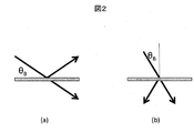
- X-ray diffraction is a phenomenon in which X-rays are diffracted (reflected) by a single crystal crystal lattice when a certain condition (Bragg condition) is satisfied when X-rays are incident on a single crystal such as silicon. . It is classified into two types, the Bragg case and the Laue case, from the geometrical arrangement. As shown in FIG. 2A, the Bragg case has a simple reflection because the diffraction X-ray is formed on the same crystal plane (surface) as the incident X-ray. When the crystal plate is thin relative to X-rays, X-rays transmitted from the back surface are simultaneously formed. On the other hand, as shown in FIG. 2 (b), the Laue case is an arrangement in which diffracted X-rays and transmitted X-rays are simultaneously formed on a crystal plane (back surface) different from that of the incident, and the beam is split.
- ⁇ is the X-ray wavelength
- ⁇ B is the Bragg angle
- d is the interplanar spacing of the crystal lattice that produces diffraction.
- X-rays with a specific energy can be extracted with a single crystal, so as shown in FIG. 3, a plurality of crystals (in the figure, the first crystal and the second crystal, (a) is a Bragg (B) is a Laue case) arranged in series in the optical path of incident X-rays, it becomes possible to simultaneously extract X-rays of a plurality of energies. Furthermore, since the extraction angle can be adjusted by using an appropriate diffraction grating surface, the X-rays of the extracted energy can intersect at one point as shown in FIG. If a subject is placed at this intersection, X-rays with a plurality of energies can be irradiated simultaneously.
- Each X-ray transmitted through the subject may be detected together with each individual X-ray camera or a large-field X-ray camera.
- CT measurement can be realized by rotating a subject relative to incident X-rays and detecting a projected image at each angle, as in the past.
- the present invention by utilizing X-ray diffraction, among the polychromatic X-rays emitted from the X-ray source, only the X-rays having the energy required for measurement are taken out and simultaneously irradiated onto the sample to display each image. Obtainable. This makes it possible to observe substances having the same linear absorption coefficient but different densities, and to visualize specific elements, which was difficult to distinguish in the past.
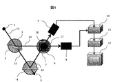
- FIG. 4 is a configuration diagram of an example of an X-ray imaging apparatus used in the present invention.
- the X-ray imaging apparatus includes an X-ray source 1, a first crystal plate 2, a first crystal plate positioning mechanism 3, a second crystal plate 4, a second crystal plate positioning mechanism 5, an object holder 6, A subject rotation positioning mechanism 7, a first X-ray camera 8, a second X-ray camera 9, a control unit 10, a processing unit 11, and a display device 12 are configured.
- the multicolor X-rays 13 emitted from the X-ray source 1 enter the first crystal plate 2 positioned by the first crystal positioning mechanism 3 and are reflected only by X-rays having a specific energy E1 that satisfies the Bragg condition. , X-rays 14 are formed.
- the X-ray 15 having the remaining energy transmitted through the first crystal plate 2 is incident on the second crystal plate 4 positioned by the second crystal positioning mechanism 5.
- only X-rays having a specific energy E 2 that satisfies the Bragg condition among the X-rays 15 are reflected to form X-rays 16.
- X-rays 14 and 16 have different angles of reflection and intersect at position 17.
- the subject 18 held by the subject holder 6 is positioned at a position 17 by the subject rotation positioning mechanism 7.
- the X-rays 14 and 16 transmitted through the subject 18 are detected by the first X-ray camera 8 and the second X-ray camera 9, respectively.
- the processing unit 11 uses the detected image to obtain a spatial distribution image, that is, an image at each energy of the subject or an image capable of separating substances, and displays the image on the display 12.
- the cross-sectional image of the subject is measured by the following procedure under the control of the control unit 10. 1.
- the rotation of the first crystal plate is adjusted by the first crystal positioning mechanism 3 so that X-rays having a desired energy are reflected by the first crystal plate 2.
- the rotation of the second crystal plate is adjusted by the second crystal positioning mechanism 5 so that X-rays having a desired energy are reflected by the second crystal plate 4.
- the subject rotation positioning mechanism 7 captures a projected image as a background while the subject 18 is retracted from the X-rays 16 and 14. 4).
- the subject rotation positioning mechanism 7 places the subject 18 at the intersection 17 of the X-rays 14 and 16, and the first camera 8 and the second camera 9 simultaneously capture an image transmitted through the subject 18. 5.
- the subject rotation positioning mechanism 7 rotates the subject 18 with respect to the X-rays 14 and 16. 6.2. To 3. The above procedure is repeated until the rotation angle reaches 180 degrees or 360 degrees. During this time, the subject 18 is withdrawn from the optical path at appropriate intervals, and a projected image as a background is captured a plurality of times.
- the X-ray source 1, the first crystal plate 2 and the positioning mechanism 3, the second crystal plate 4 and the positioning mechanism 5, the first X-ray camera 8 and the second X-ray camera 9 are synchronized.
- the above devices may be rotated simultaneously.
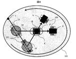
- the positioning mechanism 3 and the positioning mechanism 5 are adjusted by the parallel movement adjusting mechanism 102 that can move in parallel with the X-ray 13 so as to coincide with the rotation center of the rotating mechanism 101 and the intersection 17 of the X-rays 14 and 16.
- the position of the device can be adjusted.
- the X-ray source 1 a general tube or a rotary type may be used, or synchrotron radiation may be used.
- the intensity of the X-rays 14 and 16 can be made substantially equal to the intensity of the X-rays 14 and 16 by adjusting the voltage applied to the tube.
- very strong X-rays can be used, and the measurement time can be greatly shortened.
- Equation 6 Since the energy of the X-ray diffracted by the crystal plate is given by Equation 6, high stability is required for the incident angle. For this reason, a rotating stage with high positioning accuracy employing a tangential bar or the like is used as the rotating mechanism of each crystal positioning mechanism. When the intensity of incident X-rays is strong, the reflectance and the energy of X-rays 14 and 16 can be stabilized by cooling the crystal plate with water.
- a Bragg case or a Laue case may be used for the X-ray diffraction of the first and second crystal plates.
- X-rays that are diffracted (reflected) are characterized by no loss of intensity due to absorption of the crystal plate.
- the optical path in the crystal plate of the transmitted X-ray becomes long, the intensity loss of X-rays of other energy becomes large.
- the Bragg angle is generally as shallow as several tens of degrees, the length of the crystal plate becomes long and a large positioning mechanism is required.
- diffracted X-rays are also emitted from the back surface of the crystal, so that a loss of strength occurs with transmission, but there is an advantage that the crystal plate can be made small.
- the intensity difference between the X-rays 14 and 16 can be reduced.
- the thickness of the first crystal plate is made thinner than the thickness of the second crystal plate, the intensity difference between the X-rays 14 and 16 can be reduced.
- the absorptivity ⁇ E1 t 1 of the first crystal plate (thickness t 1 ) with respect to the energy of the X-ray 14 is combined with the first crystal plate and the second crystal plate with respect to the energy of the X-ray 16.
- the intensities of the X-rays 14 and 16 can be made equal. For example, if the energy of X-ray 14 is 35 keV, the energy of X-ray 16 is 52 keV, the first crystal plate is silicon and the thickness is 1 mm, the absorption rate of X-rays with energy 35 keV by the first crystal plate is The X-ray absorption rate of 15% and 52 keV is 5%.
- the absorption rate of the X-ray with an energy of 52 keV by the second crystal plate needs to be about 10%, and the thickness in the case of silicon is 2 mm.
- the ratio of the two intensities is equal, an image having the same S / N can be acquired with the same exposure time, so that an image with fewer artifacts (a pseudo-generated pattern) can be reconstructed.
- the first X-ray camera 8 and the second X-ray camera 9 may be composed of a scintillator + relay lens system + visible light camera, or an X-ray Sachicon tube or a harpicon tube.
- the light emission efficiency can be optimized by exchanging the scintillator with GOS, CsI or the like corresponding to the energy of the X-rays 14 and 16.
- the relay lens system may be a combination of a plurality of lenses or a fiber coupling.
- an arbitrary magnification can be set.
- the magnification is fixed, but it is possible to capture the light emitted from the scintillator at a high solid angle, and the measurement can be performed with less X-ray intensity.
- a large-field X-ray camera 104 can be used instead of the first and second X-ray cameras as shown in FIG. .
- the image is slightly blurred, but the control can be further simplified and the positioning can be facilitated.
- An arbitrary value can be adopted as the energy of the X-rays 14 and 16, but for example, if the value is slightly larger than the absorption edges of iodine and gadolinium, which are constituent elements of the scintillator of the X-ray camera, conversion of the scintillator Efficiency can be greatly improved.
- Cu distribution is obtained from the difference of the obtained image by setting it to 8.5 keV and 9keV before and after the absorption edge of K, L, M, etc. of a specific element, for example, around 8.8 keV of Cu K absorption edge. An image can be obtained.
- the processing unit 11 obtains an image capable of discriminating substances by performing weighted addition on the cross-sectional images obtained by reconstructing the images individually from the images obtained by the first and second X-ray cameras. Further, when the movement of the subject can be ignored, the cross-sectional image reconstruction calculation may be performed after the above weighted addition is performed for each projection image. In this case, the influence of the artifact can be further reduced by further weighted addition of the artifact of the cross-sectional image for each energy.
- Example 1 since only two crystal plates were used, measurement could be performed only with two X-rays having different energies.
- FIG. 5 shows the configuration of the X-ray imaging apparatus according to the present invention, in which a crystal plate 19, the positioning mechanism 20, and an X-ray camera 21 are further added to the configuration of the first embodiment.
- each device element in the present embodiment is the same as that in the first embodiment.
- X-rays emitted from the X-ray source are sequentially incident on a group of crystal plates arranged in series, and X-rays having desired energy in each crystal plate. Take out.
- the extraction angle can be adjusted by appropriately selecting the diffraction grating surface, and in this embodiment, the X-rays of each energy are adjusted so as to intersect at a certain point in space.
- the subject is placed at this intersection, and each X-ray transmitted through the subject is detected individually or with a large-field X-ray camera.
- the linear absorption coefficient is the product of the mass absorption coefficient and the density
- the density of each element can be uniquely determined.
- the density of each element can be quantitatively determined by imaging with X-rays of three different energies.
- the number of types of constituent elements is larger than the types of X-ray energy, it is possible to observe substances with the same linear absorption coefficient but different densities, and to visualize specific elements, which is difficult to distinguish as the number of types increases. Can do.
- Examples 1 and 2 since the X-rays were simply reflected by the crystal plate, the observation field of view was limited by the size of the incident X-rays. For this reason, incident X-rays with a large size are required for observation of a large field of view, and the crystal plate has to be enlarged.
- an embodiment is shown in which a large field of view can be observed with small incident X-rays by utilizing asymmetric reflection of an asymmetric crystal plate.
- X-ray asymmetric reflection is X-ray diffraction by a diffraction grating plane that is not parallel to the crystal surface.
- the asymmetry factor b is ⁇
- ⁇ B is the Bragg angle.
- the width of the diffracted X-ray is expanded to 1 / b times the width of the incident X-ray. Therefore, the incident X-ray beam can be expanded in the lateral direction and a large field of view can be observed by the crystal plate in which ⁇ is adjusted in accordance with the X-ray energy to be extracted. For example, if the incident X-ray beam width is 5 mm and the silicon plate is 1 mm thick, and X-rays with an energy of 17.8 keV are reflected by diffraction of the (220) Bragg case, the Bragg angle is 10.5 degrees.
- the present embodiment by utilizing X-ray diffraction by an asymmetric crystal, among the polychromatic X-rays emitted from the X-ray source, only the X-rays having the energy required for measurement are enlarged and extracted, and at the same time Each image can be obtained by irradiating the sample. As a result, it is possible to observe substances having the same linear absorption coefficient but different density in a large visual field, and to visualize specific elements.
- FIG. 7 shows the configuration of the X-ray imaging apparatus according to the present invention.
- an X-ray of each energy is added with a condensing element and a subject scanning mechanism for scanning the subject at high speed, and the image detector has each energy. It is the structure replaced with the intensity detector which detects the intensity
- the X-ray 14 is condensed by the second condensing element 23 and the X-ray 16 is condensed by the second condensing element 23 so that the diameter of the beam is submicron.
- the X-rays that have passed through the subject 18 are individually detected by the first intensity detector 24 and the second detector 25.
- control unit 10 controls the subject scanning mechanism 26 and the subject positioning mechanism 7 that scan the subject with respect to each X-ray, scans and rotates the respective condensed X-rays, and outputs the projection image at each angle. get.
- processing unit 11 individually reproduces the cross-sectional image from the acquired projection image by reconstruction processing, and obtains an image that can discriminate substances by weighted addition of the reproduced images. The obtained image is displayed on the display unit 12.
- the measurement is performed according to the following procedure. 1.
- the rotation of the first crystal plate 2 is adjusted by the first crystal positioning mechanism 3 so that X-rays having a desired energy are reflected by the first crystal plate 2.
- the first condensing element 22 is adjusted, and the reflected X-ray 14 is condensed to submicron or less.
- the relative position and angle of the first focusing element with respect to the X-ray beam are appropriately changed by the first focusing element position adjusting mechanism 27 so that the X-ray beam 14 at the position of the subject 18 is minimized.
- the condensing state (beam shape) may be confirmed using a change in intensity of the obtained transmitted X-ray beam by scanning a knife edge composed of a lead or tantalum blade at the object position. 3.
- the rotation of the second crystal plate is adjusted by the second crystal positioning mechanism 6 so that X-rays having a desired energy are reflected by the second crystal plate 5.
- the second condensing element 23 is adjusted by the same method using the second condensing element position adjusting mechanism 28, and the reflected X-ray 16 is condensed to submicron or less. 5.
- the subject 18 is scanned with respect to the condensed X-rays 14 and 16, and the X-ray intensity of each energy at each position is measured by the first intensity detector 24 and the second intensity detector 25, respectively. To do. Thereby, a projection image of the subject 18 at each energy is obtained. 6).
- the subject rotation positioning mechanism 7 rotates the subject 18 with respect to the X-ray. 7.5. To 6. The above procedure is repeated until the rotation angle reaches 180 degrees or 360 degrees.
- the reconstruction calculation of the cross-sectional image from the projection image obtained as described above is performed by the processing unit 11 in the same procedure as in the first embodiment, and the result is displayed on the display unit 12.
- a stage driven by a motor may be used as the subject scanning mechanism 26.
- a stage employing a piezoelectric element may be used. Since the piezoelectric element can be driven at a higher speed than the motor, the measurement time can be shortened.
- the weight that can be mounted is limited, the rotary stage cannot be mounted on the upper part. For this reason, it is indispensable to install it above the subject positioning mechanism.
- the controller 10 sequentially calculates each angle and drives based on the result.
- a Fresnel zone plate (FZP) using diffraction, a mirror using total reflection of X-rays, or the like can be used. Since FZP can easily obtain a condensed X-ray beam simply by being installed in the optical path of X-rays, adjustment can be made very simple. However, since the utilization efficiency of X-rays is low, a long measurement time is required, and since the condensing position changes depending on the X-ray energy used, it is necessary to readjust each time the energy is changed.
- the total reflection mirror is generally composed of a plurality of spherical or ellipsoidal mirrors, so that complicated angle and position adjustment is necessary, but the condensing position does not depend on the energy of the X-ray, Since the use efficiency of X-rays is high, the measurement time can be shortened. Therefore, a suitable condensing element may be selected in consideration of the change frequency of X-ray energy, the presence or absence of energy scanning, and the measurement time.
- a cross-sectional image in which the influence of the spread of the condensed X-ray beam is reduced by calculation can be obtained. Therefore, the inside of the subject can be observed nondestructively with high spatial resolution.
- each device may be rotated instead of rotating the subject.
Landscapes
- Health & Medical Sciences (AREA)
- Toxicology (AREA)
- Physics & Mathematics (AREA)
- Life Sciences & Earth Sciences (AREA)
- Chemical & Material Sciences (AREA)
- Analytical Chemistry (AREA)
- Biochemistry (AREA)
- General Health & Medical Sciences (AREA)
- General Physics & Mathematics (AREA)
- Immunology (AREA)
- Pathology (AREA)
- Analysing Materials By The Use Of Radiation (AREA)
Description
本発明はX線撮像装置及びX線撮像方法に係わり、特に、物体の内部を非破壊に高い空間分解能で検査するのに適したX線撮像装置及び方法に関する。
被写体内部を非破壊で観察する方法として、X線CT(Computed Tomography)が医療診断や製品の検査等に広く利用されている。X線CTはX線の物質に対する非常に高い透過能を利用した撮像方法で、X線を被写体に対して相対的に回転させながら照射し、透過してきたX線の空間的な強度分布像(投影像、あるいは透過像と呼ぶ)を各角度毎に取得し、取得した透過像から再構成と呼ばれる計算により被写体の断面像を再生する方法である。
図1に示したようにyr軸方向(xr-yr座標系は原点を中心に角度θだけx-y座標系を回転した系)からX線を照射した場合,試料を透過したX線の強度分布Iθ(xr)は,yr軸に沿った線積分として

で与えられる。ここで,Ioは入射するX線の強度,μ(xr, yr)は試料内部の各位置(xr, yr)における吸収率である。数1に対数変換を施し,さらに両辺をIoで除算すると,ln(Iθ(xr)/Io)で定義される投影データpθ(xr)は,
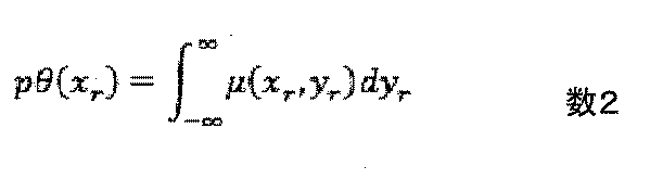
となる。この式は,μ(xr, yr)のラドン変換,あるいはθ方向へのプロジェクション(投影)と呼ばれている。したがって,θを0から2πまで回転して得られた投影データ群をラドン逆変換(再構成計算)することによって,μ(xr, yr)の分布像、すなわち被写体のμをコントラストとする断面像を求めることができる(非特許文献1)。
吸収率μは線吸収係数とも呼ばれ、エネルギーと物質によって決まるが、同じ物質でもその状態(凝集など)によって異なる。このため、μを物質の密度ρで割った値μ/ρは物質の状態に関係せず一定になり、質量吸収係数と呼ばれる。物質が複数の元素から構成されている混合物や化合物の質量物質係数は、各成分の質量吸収係数と重量比を用いて表される。混合物の場合は、

となる。ここで、x1、x2、・・・はそれぞれの元素の重量百分率である。化学式AxByとなる化合物の場合は、
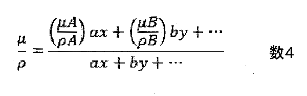
となる。ここで、a、b、・・・はそれぞれの元素A、Bの原子量である(非特許文献2)。
線吸収係数は、質量吸収係数と密度の積で与えられるため、質量吸収係数が異なる混合物や化合物でも、密度状態によっては線吸収係数μが同じになってしまい、識別できなくなるという場合がある。この問題を解決する方法として、複数のエネルギーのX線を利用した撮像法がある。一般には異なる2つのエネルギーで実施されるため、デュアルエネルギースキャンと呼ばれている。この方法では、質量吸収係数がエネルギーに依存して変化するのに対して、密度はエネルギーに対して不変なことを利用して、線吸収係数が等しいが密度が異なる物質の観察を可能にしている。
元素AとBから構成された被写体をエネルギーが異なる2種類のX線(エネルギーE1とE2)で測定したとき、元素AとBの密度をそれぞρAとρBとすると、エネルギーE1に対する線吸収係数μ1、エネルギーE2に対する線吸収係数μ2はそれぞれ、
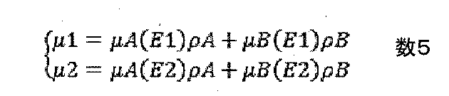
で与えられる。ここで、μA(E1)、μA(E2)、μB(E1)、μB(E2)、は元素AとBのエネルギーE1とE2における質量吸収係数で、既知な量である。このため、上式はρAとρBに関する連立方程式となり、未知数2に対して、式が2個与えられるために、一意に解くこと、すなわち一意に元素AとBの密度を算出することができる。また、3元素以上では2種類のエネルギーのX線で得られた像だけでは各元素の密度を一意に求めることはできない。しかし、質量吸収係数はエネルギーによって変化するため、仮にエネルギーE1で同じ線吸収係数になり、区別することができなくても、エネルギーE2では必ず異なる線吸収係数となるために、両者を識別することが可能になる。
また、各元素には吸収端と呼ばれるX線の吸収が急激に変化する固有のエネルギーがある。このエネルギーの前後で像を取得し、その差分を計算することによって対象となる元素だけ抽出した像(元素マッピング)を得ることも可能になる。以上のように、複数のエネルギーのX線を利用することによって、従来は区別が難しかった線吸収係数が等しいが密度が異なる物質の観察や、特定元素の可視化を可能にすることができる。
上記のデュアルエネルギースキャンを行う方法として、これまでにX線源として利用している管球に加える電圧を変化させる方法などが考案されている(非特許文献3)。
科学計測のための画像データ処理、河田聡、CQ出版(1994年)、p.221~2
X線回折・散乱技術、菊田惺志、東京大学出版会(1992年)、p.66~68
" Objective characterization of GE discovery CT750 HD scanner: gemstone spectral imaging mode.", Zhang D, Li X, Liu B., Med Phys. 2011 Mar; 38(3): 1178-88.
しかし上記の従来法では、電圧を高速に切り替える特殊な電源が必要になることや,極わずかではあるが時間差が生じること、或いは線源がシンクロトロン放射光などの場合は原理的に適用することができないなどの問題がある。
本発明ではX線源から出射した多色X線を複数の結晶板に入射し、測定に必要なエネルギーのX線を、以下に示すX線回折により選択的に取り出す。そして、取り出した各エネルギーのX線を同時に試料に照射して各画像を得る。これにより、従来は区別が難しかった線吸収係数が等しいが密度が異なる物質の観察や、特定元素の可視化を可能にすることができる。
X線回折は、シリコン等の単結晶にX線を入射した際に、ある条件(ブラッグ条件)が満されると単結晶の結晶格子でX線が回折(反射)される現象のことである。その幾何学的な配置から、ブラッグのケースとラウエのケースの2種類に分類される。ブラッグのケースは、図2(a)に示すように回折X線が入射X線と同じ結晶面(表面)で形成される配置で、単純な反射となる。結晶板がX線に対して薄い場合には、裏面から透過したX線が同時に形成される。一方、ラウエのケースは図2(b)に示すように、入射とは異なる結晶面(裏面)で回折X線と透過X線が同時に形成される配置で、ビームの分割となる。
上記いずれのケースでもブラッグ条件は不変で以下に示す式で与えられる。

ここで、λはX線の波長、θBはブラッグ角、dは回折を生じる結晶格子の面間隔である。入射X線が様々なエネルギーを含んだ多色或いは白色X線の場合、上記条件を満たさないエネルギーのX線は、結晶を単に透過することになる。したがって、この現象を利用することによって、任意のある特定のエネルギーを持ったX線のみを取り出すことが可能になる。さらに、取り出す角度(θB、ブラッグ角)は、適当な面間隔dを持った格子面を利用することによって、任意に調整することができる。
このように1個の結晶で、ある特定のエネルギーのX線を取り出すことができるので、図3に示すように複数個の結晶(図では第1結晶と第2結晶で、(a)はブラッグのケース、(b)はラウエのケース)を入射X線の光路に直列に並べることによって、複数のエネルギーのX線を同時に取り出すことが可能になる。さらに、取り出す角度は、適当な回折格子面を利用することによって調整できるので、取り出した各エネルギーのX線を図3に示すように一点で交差させることができる。そして、この交差点に被写体を設置すれば、同時に複数のエネルギーのX線を照射することができる。なお、被写体を透過した各X線は、各個別のX線カメラ、或いは大視野のX線カメラで一緒に検出すればよい。また、CTの測定は従来と同様に、被写体を入射X線に対して相対的に回転させて各角度で投影像を検出することによって、実現することができる。
本発明に依れば、X線回折を利用することによって、X線源から出射した多色X線のうち、測定に必要なエネルギーのX線のみを取り出し、同時に試料に照射して各画像を得ることができる。これにより、従来は区別が難しかった線吸収係数が等しいが密度が異なる物質の観察や、特定元素の可視化が可能になる。
以下、図面を用いて本発明の実施例について説明する。以下に示す図において、同じ機能を有する部分には同じ符号を付し、重複する説明を省略する。
図4は本発明で使用するX線撮像装置の一例の構成図である。同図に示すように本X線撮像装置は、X線源1、第1結晶板2、第1結晶板位置決め機構3、第2結晶板4、第2結晶板位置決め機構5、被写体ホルダー6、被写体回転位置決め機構7、第1X線カメラ8、第2X線カメラ9、制御部10、処理部11、及び表示装置12から構成される。
X線源1から放射された多色のX線13は、第1結晶位置決め機構3により位置決めされた第1結晶板2に入射し、ブラッグ条件を満足する特定のエネルギーE1のX線のみ反射され、X線14を形成する。第1結晶板2を透過した残りのエネルギーを有したX線15は、第2結晶位置決め機構5で位置決めされた第2結晶板4に入射する。第2結晶板4では、X線15のうちブラッグ条件を満足する特定のエネルギーE2のX線のみ反射され、X線16を形成する。X線14と16は反射された角度が異なっており、位置17で交差する。被写体ホルダー6で保持された被写体18は、被写体回転位置決め機構7により、位置17に位置決めされる。被写体18を透過したX線14及び16は、第1X線カメラ8及び第2X線カメラ9でそれぞれ検出される。処理部11では検出された像を用いて、演算により、空間分布像、即ち、被写体の各エネルギーにおける像や、物質の分別が可能な像を求め、表示器12により表示する。
本装置において被写体の断面像は、制御部10の制御の元、以下の手順により測定する。
1.第1結晶板2で所望のエネルギーのX線が反射されるように、第1結晶位置決め機構3により第1結晶板の回転を調整する。
2.第2結晶板4で所望のエネルギーのX線が反射されるように、第2結晶位置決め機構5により第2結晶板の回転を調整する。
3.被写体回転位置決め機構7により、被写体18をX線16および14から待避させた状態で、背景となる投影像を撮影する。
4.被写体回転位置決め機構7により、被写体18をX線14および16の交点17に設置し、被写体18を透過した像を第1カメラ8及び第2カメラ9で同時に撮像する。
5.被写体回転位置決め機構7により、被写体18をX線14および16に対して回転させる。
6.2.から3.の手順を回転角度が180度、あるいは360度になるまで繰り返す。また、この間に、適当な間隔で被写体18を光路から待避させ、背景となる投影像の撮影を複数回行う。
1.第1結晶板2で所望のエネルギーのX線が反射されるように、第1結晶位置決め機構3により第1結晶板の回転を調整する。
2.第2結晶板4で所望のエネルギーのX線が反射されるように、第2結晶位置決め機構5により第2結晶板の回転を調整する。
3.被写体回転位置決め機構7により、被写体18をX線16および14から待避させた状態で、背景となる投影像を撮影する。
4.被写体回転位置決め機構7により、被写体18をX線14および16の交点17に設置し、被写体18を透過した像を第1カメラ8及び第2カメラ9で同時に撮像する。
5.被写体回転位置決め機構7により、被写体18をX線14および16に対して回転させる。
6.2.から3.の手順を回転角度が180度、あるいは360度になるまで繰り返す。また、この間に、適当な間隔で被写体18を光路から待避させ、背景となる投影像の撮影を複数回行う。
なお、図8に示すように,X線源1、第1結晶板2及び同位置決め機構3、第2結晶板4及び同位置決め機構5、第1X線カメラ8及び第2X線カメラ9を同期に回転させる大きな回転機構101の上に配置し、被写体18を回転させる代わりに、上記各装置を同時に回転させても良い。また、回転機構101の回転中心と、X線14及び16の交点17に一致するように位置決め機構3及び位置決め機構5をX線13に対して平行に移動できる平行移動調整機構102により調整し,さらにこれに対応して第1X線カメラ8及び第2X線カメラ9の位置を調整するカメラ位置決め機構103を設けることにより、X線14或いは16のエネルギーE1或いはE2を変化させた場合、簡単に各装置の位置を調整することができる。
X線源1として、一般的な管球或いはロータリー型のものを用いても良いし、シンクロトロン放射光を用いても良い。前者の場合は、管に印加する電圧を調整することによって、X線14と16の強度がX線14と16の強度がほぼ等しくなるようにすることができる。一方、後者の場合、非常に強いX線を利用することができ、測定時間を大幅に短縮することができる。
結晶板によって回折されるX線のエネルギーは数6で与えられるので、入射角度には高い安定性が要求される。このため、各結晶位置決め機構の回転機構には、タンジェンシャルバーなどを採用した位置決め精度の高い回転ステージを用いる。また、入射X線の強度が強い場合、結晶板を水冷することによって、反射率やX線14および16のエネルギーを安定化することできる。
第1及び第2結晶板のX線回折には、ブラッグのケースを用いても良いし、ラウエのケースを用いても良い。ブラッグのケースの場合、回折は結晶板の表面で生じるために、回折(反射)されるX線には結晶板の吸収による強度の損失がないという特徴がある。一方、透過するX線の結晶板内の光路は長くなるために、他のエネルギーのX線の強度損失は大きくなる。また、一般にブラッグ角は数10度と浅いために、結晶板の長さが長くなり、大きな位置決め機構が必要になる。ラウエケースの場合は、回折されるX線も結晶の裏面から出射するために、透過に伴い強度の損失が発生するが、結晶板を小さくすることができるというメリットがある。
X線のエネルギーが低いほど、結晶板を透過する時に生じる吸収が大きくなるために、第1結晶板で取り出すエネルギーは、第2結晶板で取り出すエネルギーより低くすると、X線14と16の強度差を小さくすることができる。このように,第1の結晶板の厚さを,第2結晶板の厚さよりも薄くすると,X線14と16の強度差を小さくできる。また、ラウエケースの場合、X線14のエネルギーに対する第1結晶板(厚さt1)の吸収率μE1t1と、X線16のエネルギーに対する第1結晶板と第2結晶板を合わせた吸収率μE2t1+μE2t2が等しくなるように、第2結晶板の厚さを調整することによって、X線14と16の強度を等しくすることができる。例えば、X線14のエネルギーを35keV、X線16のエネルギーを52keV、第1結晶板をシリコンとしてその厚さを1 mmとした場合、第1結晶板によるエネルギー35 keVのX線の吸収率は15%、52 keVのX線の吸収率は5%となる。このため、X線14と16の強度をほぼ等しくするためには、第2結晶板によるエネルギー52 keVのX線の吸収率は10%程度にする必要があり、シリコンの場合の厚さは2 mmとなる。なお,両強度の比が等しい場合,同じ露光時間で同じS/Nの画像を取得できるので,よりアーチファクト(擬似的に発生する模様)の少ない像を再構成することができる。
第1X線カメラ8及び第2X線カメラ9として、シンチレータ+リレーレンズ系+可視光カメラから構成されたものを用いても良いし、X線用のサチコン管やハーピコン管を用いても良い。前者の場合は、X線14及び16のエネルギーに対応してシンチレータをGOSやCsIなどに交換して発光効率の最適化を図ることができる。また、リレーレンズ系としてレンズを複数枚組み合わせたものでも良いし、ファイバーカップリングものを用いて良い。前者の場合、任意の倍率に設定することができる。一方、後者の場合、倍率は固定となるが、シンチレータの発光を高い立体角で取り込むことが可能で、より少ないX線強度でも測定することができる。
X線14と16の角度差が小さく、両光路が大きく離れていないときは、図9に示すように第1及び第2X線カメラの代わりに、大視野のX線カメラ104を用いることもできる。この場合、X線14と16がカメラに垂直に入射しなくなるために、像が若干ぼけることになるが、制御がより簡略化することができ、さらに位置決めも容易になる。
X線14と16のエネルギーとして、任意の値を採用することができるが、例えばX線カメラのシンチレータの構成元素であるヨウ素とガドリニウムの吸収端より僅かに大きな値に設定すれば、シンチレータの変換効率を大幅に向上することができる。また、ある特定元素のK,L,Mなどの吸収端前後、例えばCuのK吸収端8.8keVの前後となる8.5 keVと9keVに設定することによって、得られた像の差分からCuの分布像を得ることができる。
処理部11では、第1及び第2X線カメラで得られた画像から、それぞれ個別に再構成処理して得られた断面像について、加重加算して物質の弁別が可能な像を求める。また、被写体の動きが無視できる場合には、各投影像について上記加重加算した後に断面像の再構成計算を行っても良い。この場合、エネルギー毎の断面像のアーチファクトをさらに加重加算することによってよりアーチファクトの影響を低減することができる。
以上、本実施例によれば、X線回折を利用することによって、X線源から出射した多色X線のうち、測定に必要なエネルギーのX線のみを取り出し、同時に試料に照射して各画像を得ることができる。これにより、従来は区別が難しかった線吸収係数が等しいが密度が異なる物質の観察や、特定元素の可視化を可能にすることができる。
実施例1では、2個の結晶板しか用いていなかったために、エネルギーの異なる2本のX線でしか測定を行うことができなかった。本実施例では、3個以上の結晶板を用いることで、エネルギーが3種類以上のX線で同時に被写体を観察可能な撮像装置の実施例を示す。なお、図5は本発明によるX線撮像装置の構成で、実施例1の構成にさらに結晶板19、同位置決め機構20、及びX線カメラ21を追加した構成となっている。
本実施例における各装置要素の役割は実施例1と同じで、X線源から出射されたX線を直列に配置された結晶板群に順次入射し、各結晶板で所望するエネルギーのX線を取り出す。取り出す角度は回折格子面を適当に選ぶことによって調整することが可能で、本実施例では各エネルギーのX線が空間上のある点で交差するように調整する。被写体はこの交点に設置し、被写体を透過した各X線は、個別に或いは大視野のX線カメラで検出する。
上述したように線吸収係数は、質量吸収係数と密度の積となるために、構成元素の種類数と同じ数のエネルギーの異なるX線で測定を行うことができれば、各元素の密度を一意に決定することができる。例えば、被写体がヨウ素、炭素、カルシウムで構成されている場合、異なる3つのエネルギーのX線で撮像すれば各元素の密度を定量的に決定することができる。また、構成元素の種類数がX線のエネルギーの種類より多い場合でも、種類が多いほど区別が難しかった線吸収係数が等しいが密度が異なる物質の観察や、特定元素の可視化を可能にすることができる。
以上、本実施例によれば、3個以上の結晶板のX線回折を利用することによって、X線源から出射した多色X線のうち、測定に必要な3種類以上のエネルギーのX線のみを取り出し、同時に試料に照射して各画像を得ることができる。これにより、従来は区別が難しかった線吸収係数が等しいが密度が異なる物質の観察や、特定元素の可視化を可能にすることができる。
実施例1及び2では、結晶板でX線を単に反射していたために、観察視野は入射するX線のサイズで限定されていた。このため、大視野の観察のためにはサイズの大きな入射X線が必要で、且つ、結晶板も大型にする必要があった。ここでは、非対称結晶板の非対称反射を利用することによって、サイズの小さな入射X線で大視野の観察が可能な実施例を示す。
X線の非対称反射とは、結晶の表面に対して非平行な回折格子面によるX線回折のことで、表面と回折面のなす角度がαのとき、非対称因子bは
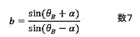
で与えられる。ここで、θBはブラッグ角である。図6のような非対称反射では、回折されたX線の幅は入射X線の幅の1/b倍に拡大される。したがって、取り出すX線のエネルギーに対応してαを調整した結晶板により、入射X線ビームを横方向に拡大し、大視野の観察を行うことできる。例えば、入射X線のビーム幅を5mm、結晶板として厚さ1mmのシリコンを使用し、エネルギー17.8 keVのX線を(220)のブラッグケースの回折により反射する場合、ブラッグ角は10.5度となるので、αを8.5度にすることによって拡大率は10倍となり、幅50mmの反射ビームを形成することができる。なお、この現象はブラッグケースでもラウエケースでも生じる現象であり、実施例1に示した両者のメリットとデメリットはそのままとなる。
以上、本実施例によれば、非対称結晶によるX線回折を利用することによって、X線源から出射した多色X線のうち、測定に必要なエネルギーのX線のみを拡大して取り出し、同時に試料に照射して各画像を得ることができる。これにより、大視野で従来は区別が難しかった線吸収係数が等しいが密度が異なる物質の観察や、特定元素の可視化を可能にすることができる。
実施例1から3では、空間分解能が画像検出器の空間分解能によってほぼ決まり、画像検出器の画素サイズ(一般に数~数10ミクロン)より向上することはできなかった。本実施例では、集光した各エネルギーのX線を被写体上で走査して画像を取得することで、空間分解能がサブミクロン以下の撮像装置の実施例を示す。図7は本発明によるX線撮像装置の構成で、実施例1の構成に各エネルギーのX線をそれぞれ集光素子と、被写体を高速に走査する被写体走査機構が加わり、画像検出器が各エネルギーのX線の強度を検出する強度検出器に替わった構成になっている。
本実施例において、X線源1から出射された多色X線のうち、第1及び結晶板で所望の各エネルギーのX線(14及び16)のみを反射により取り出し、第1集光素子22によってX線14を、第2集光素子23によってX線16をそれぞれビームの直径がサブミクロンに集光し、被写体18に照射する。そして、被写体18を透過したX線は個別に第1強度検出器24および第2検出器25で検出する。また、制御部10では、被写体を各X線に対して走査する被写体走査機構26及び被写体位置決め機構7を制御して、各集光X線に対して走査及び回転させ、各角度における投影像を取得する。そして、処理部11において、取得した投影像から、それぞれ個別に再構成処理により断面像を再生し、再生された各像の加重加算により物質の弁別が可能な像を求める。求めた像は表示部12で表示する。
本実施例において、測定は以下の手順で行う。
1.第1結晶板2で所望のエネルギーのX線が反射されるように、第1結晶位置決め機構3により第1結晶板2の回転を調整する。
2.第1集光素子22を調整し、反射されたX線14をサブミクロン以下に集光する。この調整は、第1集光素子のX線ビームに対する相対的な位置や角度などを第1集光素子位置調整機構27により適宜変化させ、被写体18の位置におけるX線ビーム14が最小となるようにする。なお、集光状態(ビーム形状)の確認は、鉛やタンタルの刃などで構成されたナイフエッジを被写体位置で走査し、得られた透過X線ビームの強度変化などを用いて行えばよい。
3.第2結晶板5で所望のエネルギーのX線が反射されるように、第2結晶位置決め機構6により第2結晶板の回転を調整する。
4.第2集光素子23を同様の方法により第2集光素子位置調整機構28を用いて調整し、反射されたX線16をサブミクロン以下に集光する。
5.被写体走査機構26を用いて、被写体18を集光X線14および16に対して走査し、各位置における各エネルギーのX線強度を第1強度検出器24及び第2強度検出器25でそれぞれ測定する。これにより、各エネルギーにおける被写体18の投影像が得られる。
6.被写体回転位置決め機構7により、被写体18をX線に対して回転させる。
7.5.から6.の手順を回転角度が180度、あるいは360度になるまで繰り返す。
1.第1結晶板2で所望のエネルギーのX線が反射されるように、第1結晶位置決め機構3により第1結晶板2の回転を調整する。
2.第1集光素子22を調整し、反射されたX線14をサブミクロン以下に集光する。この調整は、第1集光素子のX線ビームに対する相対的な位置や角度などを第1集光素子位置調整機構27により適宜変化させ、被写体18の位置におけるX線ビーム14が最小となるようにする。なお、集光状態(ビーム形状)の確認は、鉛やタンタルの刃などで構成されたナイフエッジを被写体位置で走査し、得られた透過X線ビームの強度変化などを用いて行えばよい。
3.第2結晶板5で所望のエネルギーのX線が反射されるように、第2結晶位置決め機構6により第2結晶板の回転を調整する。
4.第2集光素子23を同様の方法により第2集光素子位置調整機構28を用いて調整し、反射されたX線16をサブミクロン以下に集光する。
5.被写体走査機構26を用いて、被写体18を集光X線14および16に対して走査し、各位置における各エネルギーのX線強度を第1強度検出器24及び第2強度検出器25でそれぞれ測定する。これにより、各エネルギーにおける被写体18の投影像が得られる。
6.被写体回転位置決め機構7により、被写体18をX線に対して回転させる。
7.5.から6.の手順を回転角度が180度、あるいは360度になるまで繰り返す。
上記のより得られた投影像から断面像の再構成計算は実施例1と同様の手順により処理部11で行い、その結果を表示部12で表示する。
被写体走査機構26として、モーター駆動によるステージを用いてもよいが、モーター駆動の場合、移動の立ち上がりと立ち下がりに時間を要し、高速な動作を行うことが難しい。このため、被写体が小さく走査範囲が狭い場合は圧電素子を採用したステージを用いてもよい。圧電素子はモーターよりも高速な駆動が可能なために測定時間を短縮することができる。一方、搭載できる重量が限られているために、上部に回転ステージを搭載することができない。このため、被写体位置決め機構の上部に設置することが必須である。また、回転角度毎に走査の方向や範囲が異なることになるので、制御部10で角度毎に逐次計算し、その結果に基づいて駆動させる。
X線を集光する第1集光素子22及び第2集光素子23として、回折を利用したフレネルゾーンプレート(FZP)や、X線の全反射を利用したミラーなどを用いることができる。FZPは、X線の光路に設置するだけで集光したX線ビームが簡単に得られるので、調整を非常に簡便にすることができる。しかし、X線の利用効率が低いために長い測定時間が必要で、また、使用するX線のエネルギーによって集光位置が変化するために、エネルギーを変更する都度、再調整を行う必要がある。一方、全反射ミラーは、一般には複数枚の球面或いは楕円面ミラーで構成されているため、複雑な角度及び位置調整が必要であるが、集光位置がX線のエネルギーに依存せず、また、X線の利用効率が高いために測定時間を短縮できるという特徴がある。したがって、X線エネルギーの変更頻度やエネルギースキャンの有無、及び測定時間との兼ね合いから、適した集光素子を選択すればよい。
以上、本実施例によれば、計算により集光X線ビームの広がりの影響を低減した断面像を求めることができる。このため、高い空間分解能で被写体内部を非破壊で観察することできる。
なお、本実施例では、2つの結晶板を用いた例を示したが、3つ以上の結晶板を用いても良いし、図9のように大視野X線カメラを用いても、図8のように被写体を回転させる代わりに各装置を回転させるようにしても良いことは言うまでもない。
1 X線源
2 第1結晶板
3 第1結晶板位置決め機構
4 第2結晶板
5 第2結晶板位置決め機構
6 被写体ホルダー
7 被写体回転位置決め機構
8 第1X線カメラ
9 第2X線カメラ
10 制御部
11 処理部
12 表示装置
13 多色のX線14 X線
15 X線
16 X線
17 位置
18 被写体
19 結晶板
20 位置決め機構
21 X線カメラ
22 第1集光素子
23 第2集光素子
24 第1強度検出器
25 第2強度検出器
26 被写体走査機構
101 回転機構
102 平行移動調整機構
103 カメラ位置決め機構
104 X線カメラ
2 第1結晶板
3 第1結晶板位置決め機構
4 第2結晶板
5 第2結晶板位置決め機構
6 被写体ホルダー
7 被写体回転位置決め機構
8 第1X線カメラ
9 第2X線カメラ
10 制御部
11 処理部
12 表示装置
13 多色のX線14 X線
15 X線
16 X線
17 位置
18 被写体
19 結晶板
20 位置決め機構
21 X線カメラ
22 第1集光素子
23 第2集光素子
24 第1強度検出器
25 第2強度検出器
26 被写体走査機構
101 回転機構
102 平行移動調整機構
103 カメラ位置決め機構
104 X線カメラ
Claims (12)
- 多色X線を放射するX線源と、
前記多色X線のうち、第1のエネルギーのX線を回折する第1の結晶板と、前記多色X線のうち、前記第1のエネルギーとは異なる第2のエネルギーのX線を回折する第2の結晶板と、
前記第1のエネルギーのX線と前記第2のエネルギーのX線を、被写体が透過するように設置された前記被写体の設置台と、
前記被写体を透過した前記第1のエネルギーのX線と前記第2のエネルギーのX線とを検出する検出器と、
前記検出器で検出された透過像から、空間分布像を生成する画像処理部とを有することを特徴とするX線撮像装置。 - 前記第1の結晶板は、前記第2の結晶板よりも前記X線源側に設けられ、
前記第1の結晶板の厚さは、前記前記第2の結晶板よりも厚さが薄いことを特徴とする請求項1記載のX線撮像装置。 - 前記第1の結晶板は、前記第2の結晶板よりも前記X線源側に設けられ、
前記第1のエネルギーは、前記第2のエネルギーよりも小さいことを特徴とする請求項1記載のX線撮像装置。 - 前記第1の結晶板及び前記第2の結晶板は、前記被写体に含まれる元素のK、LまたはM吸収端前後のエネルギーのX線を回折することを特徴とする請求項1記載のX線撮像装置。
- 更に、前記第1、第2のエネルギーとは異なる第3のエネルギーのX線を回折する第3の結晶板を有することを特徴とする請求項1記載のX線撮像装置。
- 前記第1の結晶板及び前記第2の結晶板は、非対称結晶板であることを特徴とする請求項1記載のX線撮像装置。
- 前記第1の結晶板と前記設置台との間に設けられた、前記第1のエネルギーを有するX線ビームを集光する第1の集光素子と、
前記第2の結晶板と前記設置台との間に設けられた、前記第2のエネルギーを有するX線ビームを集光する第2の集光素子とを有することを特徴とする請求項1記載のX線撮像装置。 - 前記検出器は、前記第1のエネルギーのX線に対応する第1のX線カメラと、第2のエネルギーのX線に対応する第2のX線カメラを有することを特徴とする請求項1記載のX線撮像装置。
- 前記検出器は、前記第1のエネルギーのX線及び第2のエネルギーのX線を検出する1のカメラを有することを特徴とする請求項1記載のX線撮像装置。
- 前記第1の結晶板及び前記第2の結晶板は、フラッグの回折現象を利用するものであることを特徴とする請求項1記載のX線撮像装置。
- 前記第1の結晶板及び前記第2の結晶板は、ラウエの回折現象を利用するものであることを特徴とする請求項1記載のX線撮像装置。
- X線源から放射された多色X線のうち第1の結晶板で反射された第1のエネルギーのX線と、第2の結晶板で反射された前記第1のエネルギーとは異なる第2のエネルギーのX線を、両者が交差する位置に設置された被写体に同時に照射するステップと、
前記被写体を透過した前記第1のエネルギーのX線と前記第2のエネルギーのX線を検出器で検出するステップと、
前記検出器で検出された透過像から、空間分布像を生成するステップとを有することを特徴とするX線撮像方法。
Priority Applications (2)
| Application Number | Priority Date | Filing Date | Title |
|---|---|---|---|
| PCT/JP2012/073570 WO2014041675A1 (ja) | 2012-09-14 | 2012-09-14 | X線撮像装置及びx線撮像方法 |
| JP2014535318A JPWO2014041675A1 (ja) | 2012-09-14 | 2012-09-14 | X線撮像装置及びx線撮像方法 |
Applications Claiming Priority (1)
| Application Number | Priority Date | Filing Date | Title |
|---|---|---|---|
| PCT/JP2012/073570 WO2014041675A1 (ja) | 2012-09-14 | 2012-09-14 | X線撮像装置及びx線撮像方法 |
Publications (1)
| Publication Number | Publication Date |
|---|---|
| WO2014041675A1 true WO2014041675A1 (ja) | 2014-03-20 |
Family
ID=50277828
Family Applications (1)
| Application Number | Title | Priority Date | Filing Date |
|---|---|---|---|
| PCT/JP2012/073570 Ceased WO2014041675A1 (ja) | 2012-09-14 | 2012-09-14 | X線撮像装置及びx線撮像方法 |
Country Status (2)
| Country | Link |
|---|---|
| JP (1) | JPWO2014041675A1 (ja) |
| WO (1) | WO2014041675A1 (ja) |
Cited By (3)
| Publication number | Priority date | Publication date | Assignee | Title |
|---|---|---|---|---|
| JP2017072441A (ja) * | 2015-10-06 | 2017-04-13 | 浜松ホトニクス株式会社 | X線撮像装置及びx線撮像方法 |
| CN110573864A (zh) * | 2017-04-26 | 2019-12-13 | 株式会社尼康 | 检查装置、检查方法及检查对象物的制造方法 |
| JP2020094906A (ja) * | 2018-12-12 | 2020-06-18 | 日立Geニュークリア・エナジー株式会社 | 核物質量計測装置及び核物質量計測方法 |
Families Citing this family (1)
| Publication number | Priority date | Publication date | Assignee | Title |
|---|---|---|---|---|
| JP7239502B2 (ja) * | 2020-01-06 | 2023-03-14 | 株式会社日立製作所 | X線撮像装置及びx線撮像方法 |
Citations (12)
| Publication number | Priority date | Publication date | Assignee | Title |
|---|---|---|---|---|
| JPS61167846A (ja) * | 1985-01-21 | 1986-07-29 | Furukawa Electric Co Ltd:The | X線による被測定物の組成分析方法 |
| JPS61167848A (ja) * | 1985-01-21 | 1986-07-29 | Furukawa Electric Co Ltd:The | X線による被測定物の組成分析方法 |
| JPH02205760A (ja) * | 1989-02-03 | 1990-08-15 | Hitachi Ltd | 多重波長x線断層撮影装置 |
| JPH02224744A (ja) * | 1989-02-28 | 1990-09-06 | Shimadzu Corp | X線撮影装置 |
| JPH05340894A (ja) * | 1992-06-09 | 1993-12-24 | Nippon Steel Corp | K吸収端差分法を用いたx線画像撮影装置並びにx線ct装置 |
| JPH05340893A (ja) * | 1992-06-09 | 1993-12-24 | Nippon Steel Corp | K吸収端差分法を用いたx線ct装置 |
| JPH05346500A (ja) * | 1992-06-16 | 1993-12-27 | Sumitomo Electric Ind Ltd | シンクロトロン放射光の波長切換装置 |
| JPH06308295A (ja) * | 1993-04-23 | 1994-11-04 | Nippon Steel Corp | X線画像撮影装置用単結晶 |
| JP2005181083A (ja) * | 2003-12-19 | 2005-07-07 | Hitachi Zosen Corp | X線検査装置およびx線検査方法 |
| JP2007195888A (ja) * | 2006-01-30 | 2007-08-09 | Univ Nihon | パラメトリックx線を利用したアンギオグラフィーシステム |
| JP2008086760A (ja) * | 2006-10-02 | 2008-04-17 | Wonkwang Univ Center For Industry-Academy Corp | 二重照射方式の乳房撮影装置及びその装置を用いる乳房撮影方法 |
| JP2010266368A (ja) * | 2009-05-15 | 2010-11-25 | Japan Science & Technology Agency | 走査型リアルタイム顕微システムおよび走査型x線高速描画システム |
-
2012
- 2012-09-14 WO PCT/JP2012/073570 patent/WO2014041675A1/ja not_active Ceased
- 2012-09-14 JP JP2014535318A patent/JPWO2014041675A1/ja active Pending
Patent Citations (12)
| Publication number | Priority date | Publication date | Assignee | Title |
|---|---|---|---|---|
| JPS61167846A (ja) * | 1985-01-21 | 1986-07-29 | Furukawa Electric Co Ltd:The | X線による被測定物の組成分析方法 |
| JPS61167848A (ja) * | 1985-01-21 | 1986-07-29 | Furukawa Electric Co Ltd:The | X線による被測定物の組成分析方法 |
| JPH02205760A (ja) * | 1989-02-03 | 1990-08-15 | Hitachi Ltd | 多重波長x線断層撮影装置 |
| JPH02224744A (ja) * | 1989-02-28 | 1990-09-06 | Shimadzu Corp | X線撮影装置 |
| JPH05340894A (ja) * | 1992-06-09 | 1993-12-24 | Nippon Steel Corp | K吸収端差分法を用いたx線画像撮影装置並びにx線ct装置 |
| JPH05340893A (ja) * | 1992-06-09 | 1993-12-24 | Nippon Steel Corp | K吸収端差分法を用いたx線ct装置 |
| JPH05346500A (ja) * | 1992-06-16 | 1993-12-27 | Sumitomo Electric Ind Ltd | シンクロトロン放射光の波長切換装置 |
| JPH06308295A (ja) * | 1993-04-23 | 1994-11-04 | Nippon Steel Corp | X線画像撮影装置用単結晶 |
| JP2005181083A (ja) * | 2003-12-19 | 2005-07-07 | Hitachi Zosen Corp | X線検査装置およびx線検査方法 |
| JP2007195888A (ja) * | 2006-01-30 | 2007-08-09 | Univ Nihon | パラメトリックx線を利用したアンギオグラフィーシステム |
| JP2008086760A (ja) * | 2006-10-02 | 2008-04-17 | Wonkwang Univ Center For Industry-Academy Corp | 二重照射方式の乳房撮影装置及びその装置を用いる乳房撮影方法 |
| JP2010266368A (ja) * | 2009-05-15 | 2010-11-25 | Japan Science & Technology Agency | 走査型リアルタイム顕微システムおよび走査型x線高速描画システム |
Cited By (4)
| Publication number | Priority date | Publication date | Assignee | Title |
|---|---|---|---|---|
| JP2017072441A (ja) * | 2015-10-06 | 2017-04-13 | 浜松ホトニクス株式会社 | X線撮像装置及びx線撮像方法 |
| CN110573864A (zh) * | 2017-04-26 | 2019-12-13 | 株式会社尼康 | 检查装置、检查方法及检查对象物的制造方法 |
| JP2020094906A (ja) * | 2018-12-12 | 2020-06-18 | 日立Geニュークリア・エナジー株式会社 | 核物質量計測装置及び核物質量計測方法 |
| JP7178250B2 (ja) | 2018-12-12 | 2022-11-25 | 日立Geニュークリア・エナジー株式会社 | 核物質量計測装置及び核物質量計測方法 |
Also Published As
| Publication number | Publication date |
|---|---|
| JPWO2014041675A1 (ja) | 2016-08-12 |
Similar Documents
| Publication | Publication Date | Title |
|---|---|---|
| JP6039093B2 (ja) | 結晶学的結晶粒方位マッピング機能を有する実験室x線マイクロトモグラフィシステム | |
| US10352880B2 (en) | Method and apparatus for x-ray microscopy | |
| JP6448649B2 (ja) | 収集及び再構築技術を含む離調構成に基づく大視野位相差撮影法 | |
| JP5158699B2 (ja) | X線撮像装置、及び、これに用いるx線源 | |
| EP2830505B1 (en) | Hybrid pci system for medical radiographic imaging | |
| JP5838114B2 (ja) | X線トポグラフィ装置 | |
| JP2009002805A (ja) | 小角広角x線測定装置 | |
| US8644449B2 (en) | X-ray imaging apparatus and method of X-ray imaging | |
| JP5714861B2 (ja) | X線画像撮影方法およびx線画像撮影装置 | |
| EP2457112A2 (en) | X-ray imaging apparatus and x-ray imaging method | |
| JP3834652B2 (ja) | X線回折顕微鏡装置およびx線回折顕微鏡装置によるx線回折測定方法 | |
| JP6058860B2 (ja) | X線撮像装置及びx線撮像方法 | |
| WO2014041675A1 (ja) | X線撮像装置及びx線撮像方法 | |
| WO2020246220A1 (ja) | 放射線撮影システム及び拡大吸収コントラスト画像生成方法 | |
| Imai et al. | High‐Angular‐Resolution Microbeam X‐Ray Diffraction with CCD Detector | |
| JP6789591B2 (ja) | 放射線位相撮像装置 | |
| JP4604242B2 (ja) | X線回折分析装置およびx線回折分析方法 | |
| CN119688744B (zh) | 基于白光x射线的能谱ct实验装置及方法 | |
| JP2006250642A (ja) | X線回折分析方法およびx線回折分析装置 | |
| CN110520716A (zh) | Talbot x射线显微镜 | |
| WO2023203856A1 (ja) | 半導体検査装置、半導体検査システムおよび半導体検査方法 | |
| Arfelli | Recent development of diffraction enhanced imaging | |
| JP2012251834A (ja) | 暗視野画像を得る方法、暗視野画像撮影装置、及び角度分析板 | |
| Rack | White beam synchrotron topography using a high resolution digital X-ray imaging detector |
Legal Events
| Date | Code | Title | Description |
|---|---|---|---|
| 121 | Ep: the epo has been informed by wipo that ep was designated in this application |
Ref document number: 12884402 Country of ref document: EP Kind code of ref document: A1 |
|
| ENP | Entry into the national phase |
Ref document number: 2014535318 Country of ref document: JP Kind code of ref document: A |
|
| NENP | Non-entry into the national phase |
Ref country code: DE |
|
| 122 | Ep: pct application non-entry in european phase |
Ref document number: 12884402 Country of ref document: EP Kind code of ref document: A1 |