WO2014041597A1 - ガスクロマトグラフ装置 - Google Patents
ガスクロマトグラフ装置 Download PDFInfo
- Publication number
- WO2014041597A1 WO2014041597A1 PCT/JP2012/073182 JP2012073182W WO2014041597A1 WO 2014041597 A1 WO2014041597 A1 WO 2014041597A1 JP 2012073182 W JP2012073182 W JP 2012073182W WO 2014041597 A1 WO2014041597 A1 WO 2014041597A1
- Authority
- WO
- WIPO (PCT)
- Prior art keywords
- column
- line
- heating member
- separation column
- gas chromatograph
- Prior art date
- Legal status (The legal status is an assumption and is not a legal conclusion. Google has not performed a legal analysis and makes no representation as to the accuracy of the status listed.)
- Ceased
Links
Images





Classifications
-
- G—PHYSICS
- G01—MEASURING; TESTING
- G01N—INVESTIGATING OR ANALYSING MATERIALS BY DETERMINING THEIR CHEMICAL OR PHYSICAL PROPERTIES
- G01N30/00—Investigating or analysing materials by separation into components using adsorption, absorption or similar phenomena or using ion-exchange, e.g. chromatography or field flow fractionation
- G01N30/02—Column chromatography
- G01N30/26—Conditioning of the fluid carrier; Flow patterns
- G01N30/28—Control of physical parameters of the fluid carrier
- G01N30/30—Control of physical parameters of the fluid carrier of temperature
-
- G—PHYSICS
- G01—MEASURING; TESTING
- G01N—INVESTIGATING OR ANALYSING MATERIALS BY DETERMINING THEIR CHEMICAL OR PHYSICAL PROPERTIES
- G01N30/00—Investigating or analysing materials by separation into components using adsorption, absorption or similar phenomena or using ion-exchange, e.g. chromatography or field flow fractionation
- G01N30/02—Column chromatography
- G01N30/04—Preparation or injection of sample to be analysed
- G01N30/16—Injection
-
- G—PHYSICS
- G01—MEASURING; TESTING
- G01N—INVESTIGATING OR ANALYSING MATERIALS BY DETERMINING THEIR CHEMICAL OR PHYSICAL PROPERTIES
- G01N30/00—Investigating or analysing materials by separation into components using adsorption, absorption or similar phenomena or using ion-exchange, e.g. chromatography or field flow fractionation
- G01N30/02—Column chromatography
- G01N30/50—Conditioning of the sorbent material or stationary liquid
- G01N30/52—Physical parameters
- G01N30/54—Temperature
-
- G—PHYSICS
- G01—MEASURING; TESTING
- G01N—INVESTIGATING OR ANALYSING MATERIALS BY DETERMINING THEIR CHEMICAL OR PHYSICAL PROPERTIES
- G01N30/00—Investigating or analysing materials by separation into components using adsorption, absorption or similar phenomena or using ion-exchange, e.g. chromatography or field flow fractionation
- G01N30/02—Column chromatography
- G01N30/26—Conditioning of the fluid carrier; Flow patterns
- G01N30/28—Control of physical parameters of the fluid carrier
- G01N30/30—Control of physical parameters of the fluid carrier of temperature
- G01N2030/3007—Control of physical parameters of the fluid carrier of temperature same temperature for whole column
-
- G—PHYSICS
- G01—MEASURING; TESTING
- G01N—INVESTIGATING OR ANALYSING MATERIALS BY DETERMINING THEIR CHEMICAL OR PHYSICAL PROPERTIES
- G01N30/00—Investigating or analysing materials by separation into components using adsorption, absorption or similar phenomena or using ion-exchange, e.g. chromatography or field flow fractionation
- G01N30/02—Column chromatography
- G01N30/26—Conditioning of the fluid carrier; Flow patterns
- G01N30/28—Control of physical parameters of the fluid carrier
- G01N30/30—Control of physical parameters of the fluid carrier of temperature
- G01N2030/3046—Control of physical parameters of the fluid carrier of temperature temperature control of column inlet
-
- G—PHYSICS
- G01—MEASURING; TESTING
- G01N—INVESTIGATING OR ANALYSING MATERIALS BY DETERMINING THEIR CHEMICAL OR PHYSICAL PROPERTIES
- G01N30/00—Investigating or analysing materials by separation into components using adsorption, absorption or similar phenomena or using ion-exchange, e.g. chromatography or field flow fractionation
- G01N30/02—Column chromatography
- G01N30/26—Conditioning of the fluid carrier; Flow patterns
- G01N30/28—Control of physical parameters of the fluid carrier
- G01N30/30—Control of physical parameters of the fluid carrier of temperature
- G01N2030/3084—Control of physical parameters of the fluid carrier of temperature ovens
Definitions
- the present invention relates to a gas chromatograph apparatus provided with a sample introduction part, a separation column, and a detector.
- a gas chromatograph generally includes a gas introduction unit for introducing a sample gas, a separation column for separating the sample gas into components, a detector for detecting the separated sample components, and an oven.
- a gas introduction unit for introducing a sample gas
- a separation column for separating the sample gas into components
- a detector for detecting the separated sample components
- an oven In the oven, together with the separation column, piping connecting between the sample introduction part and the separation column and piping connecting between the separation column and the detector were accommodated and their temperatures were adjusted.
- the oven includes a heater and a fan, and is a heat convection type oven that uniformly heats the inside of the oven by circulating air heated by the heater.
- a sample introduction part 60 and a detector 64 are attached to the upper part of the oven 74, and inside the oven 74, a capillary 66 for connecting the sample introduction part 60 and the separation column 62 is accommodated in addition to the separation column 62.
- the capillary 66 is provided with a coiled portion 68, and the coiled portion 68 constitutes a guard column or a retention gap.
- the guard column is inserted between the sample introduction part and the separation column for the purpose of preventing the separation column from being contaminated by impurities and high-boiling components.
- the guard column may or may not have a liquid phase, but it is said that the channel length is required to be about 0.5 to 5 m.
- the guard column must be replaced or partially cut depending on the degree of contamination.
- Retention gap refers to sample introduction in order to prevent the spread of peak components and splitting of one component peak caused by the large amount of sample injection when the on-column method or splitless method is used as the sample introduction method. Is inserted between the column and the separation column.
- the capillary as the retention gap needs to be an inactivated capillary that is not coated with a liquid phase, and the channel length is generally required to be about 0.5 to 5 m.
- the problems with the above gas chromatograph device include the slow heating and cooling speed of the separation column and the power consumption due to the heat capacity of the heat convection oven.
- Patent Document since the separation column is housed in a separate container with a heating wire wound and disposed outside the oven as a column module, the heat capacity of the heating target is reduced, and the separation column is heated at a high speed. This makes it possible to improve the temperature control response of the separation column and reduce the power consumption for raising and lowering the temperature of the separation column.
- a transfer line connecting the sample introduction part and the separation column or between the separation column and the detector is installed in the oven. It is necessary to adjust the temperature separately from the separation column, and there is a limit to reducing the power consumption due to the presence of the heat convection oven. Further, when a guard column or a retention gap is inserted between the sample introduction part and the separation column, they are accommodated in a thermal convection oven.
- the effective temperature rise rate is determined by the temperature rise rate of the heat convection oven, and the temperature is adjusted compared to when the separation column is housed in the heat convection oven It is difficult to say that the improvement of the responsiveness and the reduction of power consumption are achieved.
- a separation column chip for example, a plate in which a channel is formed by bonding silicon and glass with a groove formed
- a separation column chip is used as the guard column and the retention gap.
- Patent Document 2 As another method, it has been proposed to heat the capillary by covering the periphery of the capillary constituting the transfer line with a jacket provided with a heater and heating the air in the jacket with the heater (Patent Document 2). reference).
- the space to be heated can be made smaller than the oven, the heat capacity of the object to be heated is reduced, and the temperature rise rate of the capillary can be improved. Then, by removing a part of the jacket, it is possible to perform a treatment such as replacement of the guard column or the retention gap or partial cutting.
- the temperature difference between the jacket contact portion and the non-contact portion of the capillary becomes significant. It is necessary to secure a wide space. For this reason, there is a limit in reducing the space inside the jacket, and there is a limit in improving the heating rate of the capillary.
- an object of the present invention is to improve the temperature control responsiveness of the separation column and transfer line and reduce the power consumption required for raising and lowering the temperature of the separation column.
- a gas chromatograph apparatus includes a sample introduction unit, a detector, a separation column, a transfer line connecting the sample introduction unit and the separation column, and between the sample introduction unit and the detector, and a separation column.
- a column temperature control section having a column heating member for heating the separation column in contact with the line, a line heating member for heating the transfer line in contact with the transfer line, and a line presser disposed on the opposite side of the line heating member of the transfer line
- a line temperature adjusting unit that adjusts the temperature of the transfer line by sandwiching the transfer line between the line heating member and the line pressing member.
- a column temperature adjusting unit provided with a column heating member, and a line temperature adjusting unit for adjusting the temperature of the transfer line by sandwiching the transfer line between the line heating member and the line pressing member, Because the heat capacity of the heating target when raising the temperature of the separation column is smaller than that of the heat convection oven, the responsiveness of the temperature rise and fall of the separation column is improved and the power consumption when raising the temperature of the separation column is reduced. be able to. Since the temperature of the transfer line can be quickly raised by the line temperature control unit, the temperature can be raised and lowered faster and the power consumption can be reduced as compared with the case where the temperature of the transfer line is adjusted by an oven.
- the present invention is a structure in which the transfer line is sandwiched between the line heating member and the line pressing member, and since it is not a structure in which a heater such as a heating wire is wound around the transfer line, even when a guard column or a retention gap is provided, A guard column and a retention gap made of a coil wound in a coil shape can be arranged in the line temperature control section, and the guard column and the retention gap can be exchanged or partially cut.
- the line pressing member may be a heating member that contacts the transfer line and heats the transfer line. By sandwiching the transfer line between the two heating members, the heating efficiency of the transfer line can be improved.
- the line pressing member may be a heat insulating member having flexibility.
- the heat from the line heating member can be efficiently transferred to the transfer line without dissipating it to the surroundings, so the transfer line is heated with high efficiency. It is possible to increase the response of the transfer line to the temperature rise. Since only one heating member having a heat source is required, there is an advantage that power consumption is reduced as compared with the case where the line pressing member is also constituted by the heating member.
- the line pressing member is formed of a heat insulating member
- a temperature difference is generated between the line heating member side and the heat insulating member side during heating of the transfer line, and a temperature distribution is generated in the transfer line. Therefore, as a preferred embodiment, a film-like heat conductive member is interposed between the transfer line and the line pressing member, and a part of the heat conductive member is brought into contact with the line heating member. It is done. Thereby, the heat of a line heating member can be transmitted to the heat insulation member side via a heat conductive member, and the temperature difference between the line heating member side and the heat insulation member side can be relieved.
- thermal conductive member is an aluminum foil.
- the column heating member and the line heating member may be constituted by a common heat block. By doing so, the number of parts constituting the device can be reduced, the device configuration can be simplified and the cost can be reduced.
- the column temperature control unit includes a column pressing member that is disposed on the side opposite to the column heating member of the separation column and sandwiches the separation column with the column heating member
- the line pressing member can also be constituted by a common heat block. If so, the number of parts constituting the apparatus can be further reduced, the apparatus configuration can be simplified and the cost can be reduced.
- the column temperature adjustment part is provided on the side opposite to the column heating member of the separation column and includes a column pressing member that holds the separation column between the column heating member and the column heating member
- the column pressing member and the line pressing member are flexible. You may comprise by the common heat insulation member which has property. As a result, the number of parts constituting the device can be further reduced, the device configuration can be simplified and the cost can be reduced.
- the column heating member and the line heating member may be integrated in a thermally separated state with a heat insulating member interposed therebetween.
- the transfer line and separation column can be individually controlled, and the analysis is performed by raising and lowering only the separation column while maintaining the transfer line at a constant temperature. Can be increased.
- the column temperature control part when the column temperature control part is provided on the side opposite to the column heating member of the separation column and includes a column pressing member for sandwiching the separation column between the column heating member and the column heating member,
- the pressing member can be constituted by a common heat insulating member having flexibility.
- the surface of the line heating member in contact with the transfer line is provided with a recess for fitting and holding a connection member for connecting the transfer line and the sample introduction portion and a connection member for connecting the transfer line and the detector. If it does so, the temperature of a connection member can be adjusted with a line temperature control part with the temperature of a transfer line. Then, the connection member can be efficiently heated by the line heating member by fitting and holding the connection member in the recess of the line heating member, and the connection member has a cold spot whose temperature is lower than that of other portions. Can be prevented.
- the line heating member is detachable at the portion where the concave portion is provided. Then, when removing the transfer line from the line temperature control unit, the recess of the line heating member is provided even when the sample introduction unit, the detector, and the line heating member are held in the casing of the gas chromatograph device.
- the connecting member can be exposed to the surface simply by removing the portion, and the nut constituting the connecting member can be fastened or removed.
- a recess for fitting and holding the separation column is provided on the surface of the column heating member that contacts the separation column. If it does so, the heating efficiency of the separation column by a column heating member can be improved.
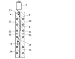
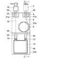
- the gas chromatograph apparatus of this embodiment includes a sample introduction unit 2, a separation column chip 10, and a detector 18, as well as a capillary 6 that connects the sample introduction unit 2 and the separation column chip 10, and a separation column chip 10 and a detector 18.
- a capillary 16 is provided to connect them.
- the capillaries 6 and 16 constitute a transfer line.
- the separation column chip 10 is a flat plate-shaped member in which a flow path and a stationary phase serving as a separation column are formed in a substrate called a chip.
- An inlet side connecting portion 12 that leads to one end of the separation column and an outlet side connecting portion 14 that leads to the other end of the separation column are provided on one plane side of the separation column chip 10.
- a separation column chip formed in a chip shape is used as the separation column.
- the present invention is not limited to this, and the capillary column is wound in a coil shape. What was formed in this way may be used as a separation column.
- the capillary 6 includes a coiled portion (hereinafter referred to as a coiled portion) 8.
- the coiled portion 8 constitutes a guard column or a retention gap.
- connection part 4 of the sample introduction part 2, the capillaries 6 and 16, the separation column chip 10 and the connection part 20 of the detector 18 are sandwiched between a heat block 22 and a heat block 30.
- the heat blocks 22 and 30 are plate-like members made of a heat conductive material such as aluminum.
- a heater 32 and a temperature sensor 33 are embedded in the heat block 22, and a heater 34 and a temperature sensor 35 are embedded in the heat block 30.
- the heater 32 is feedback-controlled based on the temperature detected by the temperature sensor 33
- the heater 34 is feedback-controlled based on the temperature detected by the temperature sensor 35.
- the heat block 22 constitutes a column heating member and a line heating member
- the heat block 30 constitutes a column pressing member and a line pressing member.
- the heat blocks 22 and 30 constitute a line temperature adjusting unit for adjusting the temperature of the transfer line and a column temperature adjusting unit for adjusting the temperature of the separation column chip 10.
- the heat block 22 and the heat block 30 are fixed in a state where they are pressed against each other, for example, by fastening screws that penetrate through the through holes provided in both the blocks 22 and 30.
- this invention is not limited to this, What kind of thing may be sufficient as long as it is the structure which presses and fixes two members which clamp a transfer line mutually.
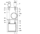
- FIG. 2 shows an embodiment in which the heat insulating member 40 is used as a column pressing member and a line pressing member instead of the heat block 30.
- the material of the heat insulating member 40 is preferably a flexible heat insulating material such as glass wool.
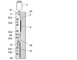
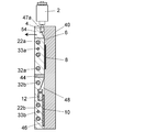
- FIG. 3A and 3B show another embodiment of the gas chromatograph apparatus.
- a heat block 22a as a line heating member and a heat block 22b as a column heating member are integrated with a heat insulating member 44 interposed therebetween. It is what was used.
- One plane of the heat block 22a is mainly in contact with the connection portions 4 and 20, and the capillaries 6 and 16, and one plane of the heat block 22b is mainly in contact with the separation column chip 10.
- the heat blocks 22 a and 22 b are thermally separated by a heat insulating member 44.
- the heat block 22a includes a heater 32a and a temperature sensor 33a
- the heat block 22b includes a heater 32b and a temperature sensor 33b.
- the heat blocks 22a and 22b are configured to be able to perform temperature adjustment independently of each other. Yes.
- the heat block 22a and the heat insulating member 40 constitute a line temperature adjusting unit
- the heat block 22b and the heat insulating member 40 constitute a column temperature adjusting unit.
- the heat block 22a mainly in contact with the transfer line and the heat block 22b mainly in contact with the separation column chip 10 are thermally separated so that the temperature can be adjusted independently of each other.
- the transfer line The degree of freedom of analysis is improved, for example, by allowing the separation column chip 10 to be heated and lowered while maintaining the temperature at a constant temperature.
- Concave portions 47 and 51 for fitting the connecting portions 4 and 20 are provided on one plane of the heat block 22a.
- a recess 46 for fitting the separation column chip 10 and recesses 48 and 50 for fitting the connection portions 12 and 14 are provided on one plane of the heat block 22b.
- FIG. 4 shows still another embodiment.
- a film-like heat conduction made of aluminum foil is provided between the coiled portion 8 and the heat insulating member 40.
- the characteristic member 52 is interposed.
- the heat conductive member 52 is provided in a size that covers the entire coiled portion 8 from the heat insulating member 40 side, and its end is in contact with the heat block 22a. Thereby, the heat of the heat block 22a is transmitted also to the heat insulation member 40 side of the coil-shaped part 8, and the whole coil-shaped part 8 is heated uniformly.
- the film-like heat conductive member 52 can be used as long as it has a low heat capacity, high heat conductivity, and flexibility.
- steel wool formed in a film form can be cited. It is done.
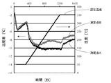
- the capillary constituting the coiled portion 8 has an inner diameter of 0 as shown in FIG.
- a large diameter capillary called a .53 mm wide bore capillary is used, a capillary (measurement point A) located closest to the heat insulating member 40 of the coiled portion 8 and a capillary located between the heat block 22a and the heat insulating member 40
- a thermocouple was inserted so as to be in contact with (measurement point B), and the temperature was measured.
- a platinum sensor was used as the temperature sensor 33a of the heat block 22a, and the heater 32a was controlled so that the measured value was raised from 50 ° C. to 350 ° C. at a rate of 20 ° C./min, and then reached a steady state at 350 ° C.
- FIG. 6 shows temperature difference data between the measurement points A and B and the heat block 22a.
- the temperature at the measurement point A was about 10 ° C. at the maximum when the temperature was raised, about 8 ° C. at the maximum at 350 ° C., and lower than the temperature of the heat block 22a.
- the temperature at the measurement point B was about 9 ° C. at the maximum during the temperature rise, about 7 ° C. at the maximum at 350 ° C., and lower than the temperature of the heat block 22a. From this result, the temperature difference between each of the measurement points A and B and the heat block 22a is about 10 ° C. at the maximum, and the capillary constituting the coiled portion 8 is heated sufficiently uniformly under this measurement condition. Can do.
- the set temperature for raising the temperature of the heat block 22a may be set higher by about 10 ° C.
- the heat blocks 22a and 22b are thermally separated by the heat insulating material 44, even if the set temperature of the heat block 22a is set higher, the temperature control of the separation column chip 10 is affected. There is nothing.
- the case where the film-like heat conductive member 52 is provided is not limited to the case where the guard column or the retention gap as in the coiled portion 8 is provided, and the case where the guard column or the retention gap is not provided. In order to improve the heating efficiency of the entire transfer line, such a heat conductive member may be used.
- the embodiment of FIG. 4 is obtained by adding a heat conductive member 52 to the embodiment of FIGS. 3A and 3B.
- the present invention is not limited to this, and the line pressing member is constituted by a heat insulating member. It can be applied if it is. Reducing the temperature distribution generated in the space between the line heating member and the heat insulating member by adding a flexible film-like heat conductive member between the transfer line and the line pressing member made of the heat insulating member Can do.
- the sample introduction unit 2, the detector 18, and the heat blocks (line heating member and column heating member) 22, 22a and 22b in the above embodiment are fixed to the casing of the gas chromatograph apparatus.
- the capillaries 6 and 16 may need to be replaced due to contamination or the like.
- the capillaries 6 and 16 need to be replaced by removing the heat block 30 or the heat insulating member 40 as the column pressing member.
- the nuts constituting the connection members 4 and 20 are simply removed by removing the heat block 30 or the heat insulating member 40. Removal and fastening work is difficult.
- FIGS. 7A and 7B show an embodiment having a structure that facilitates replacement of the capillaries 6 and 16 of the embodiment of FIGS. 3A and 3B.
- the parts 54 and 56 holding the connecting members 4 and 20 of the heat block 22a can be removed in the direction of the arrow shown in FIG. 7B.
- the parts 54 and 56 and the heat insulating member 40 are connected to each other. By removing, the operation
- This structure is not limited to the structure shown in FIGS. 7A and 7B, and can be applied to any of the embodiments described above.
- the parts 54 and 56 form a part of the heat block 22a, and in a state of being integrated with the heat block 22a, the parts 54 and 56 are sufficiently in contact with other parts of the heat block 22a to transfer heat from the heater 32a. And 20.
- the portions 54 and 56 may be thermally independent from the heat block 22a, or may have their own heater and temperature sensor.
Landscapes
- Physics & Mathematics (AREA)
- Health & Medical Sciences (AREA)
- Life Sciences & Earth Sciences (AREA)
- Chemical & Material Sciences (AREA)
- Analytical Chemistry (AREA)
- Biochemistry (AREA)
- General Health & Medical Sciences (AREA)
- General Physics & Mathematics (AREA)
- Immunology (AREA)
- Pathology (AREA)
- Other Investigation Or Analysis Of Materials By Electrical Means (AREA)
- Sampling And Sample Adjustment (AREA)
Description
さらに、本発明は、ライン加熱部材とライン押さえ部材とでトランスファーラインを挟持する構造であり、電熱線などのヒータをトランスファーラインに巻き付ける構造ではないため、ガードカラムやリテンションギャップを設ける場合にも、コイル状に巻かれたキャピラリからなるガードカラムやリテンションギャップをライン温調部内に配置することが可能であり、ガードカラムやリテンションギャップの交換や一部切断を行なうことができる。
この実施例のガスクロマトグラフ装置は試料導入部2、分離カラムチップ10、検出器18のほか、試料導入部2と分離カラムチップ10の間を接続するキャピラリ6及び分離カラムチップ10と検出器18の間を接続するキャピラリ16を備えている。以下、キャピラリ6及び16はトランスファーラインを構成する。分離カラムチップ10はチップと称される基体内に分離カラムとなる流路および固定相が形成された平板形状の部材である。分離カラムチップ10の一平面側に分離カラムの一端に通じる入口側接続部12、分離カラムの他端に通じる出口側接続部14が設けられている。
キャピラリ6はコイル状に巻かれた部分(以下、コイル状部分)8を備えている。コイル状部分8はガードカラム又はリテンションギャップを構成している。
この実施例は、図2の実施例のヒートブロック22に代えて、ライン加熱部材としてのヒートブロック22aとカラム加熱部材としてのヒートブロック22bをその間に断熱部材44を介在させながら一体化したものを用いたものである。ヒートブロック22aの一平面は主に接続部4及び20、キャピラリ6及び16に接し、ヒートブロック22bの一平面は主に分離カラムチップ10に接している。ヒートブロック22aと22bは断熱部材44によって熱的に分離されている。
図4の実施例は、図3の実施例のキャピラリ6のコイル状部分8の加熱効率を向上させるために、コイル状部分8と断熱部材40との間にアルミニウム箔からなる膜状の熱伝導性部材52を介在させたものである。熱伝導性部材52はコイル状部分8全体を断熱部材40側から覆う大きさで設けられ、その端部がヒートブロック22aと接している。これにより、ヒートブロック22aの熱がコイル状部分8の断熱部材40側にも伝えられ、コイル状部分8全体が均一に加熱される。なお、膜状の熱伝導性部材52としては、低熱容量、高熱伝導率で柔軟性のあるものであれば用いることができ、アルミニウム箔の他に、例えば膜状に形成されたスチールウールが挙げられる。
なお、部分54及び56はヒートブロック22aとは熱的に独立したものであってもよく、独自のヒータと温度センサを備えていてもよい。
4,20 接続部材
6,16 キャピラリ(トランスファーライン)
8 コイル状部分(ガードカラム又はリテンションギャップ)
10 分離カラムチップ
12 入口側接続部(分離カラム)
14 出口側接続部(分離カラム)
18 検出器
22,22a,22b,30 ヒートブロック
23,24,26,28,29,47,47a,48,50,51,51a 凹部
32,32a,32b,34 ヒータ
33,33a,33b,35 温度センサ
40,44 断熱部材
52 熱伝導性部材
Claims (13)
- 試料導入部と、
検出器と、
分離カラムと、
前記試料導入部と前記分離カラムとの間及び前記試料導入部と前記検出器との間を接続するトランスファーラインと、
前記分離カラムに接して前記分離カラムを加熱するカラム加熱部材を備えたカラム温調部と、
前記トランスファーラインに接して前記トランスファーラインを加熱するライン加熱部材及び前記トランスファーラインの前記ライン加熱部材とは反対側に配置されたライン押さえ部材を備え、前記ライン加熱部材と前記ライン押さえ部材とで前記トランスファーラインを挟持して前記トランスファーラインの温度調節を行なうライン温調部と、を備えたガスクロマトグラフ装置。 - 前記ライン押さえ部材は前記トランスファーラインに接して前記トランスファーラインを加熱する加熱部材である請求項1に記載のガスクロマトグラフ装置。
- 前記ライン押さえ部材は柔軟性をもつ断熱部材である請求項1に記載のガスクロマトグラフ装置。
- 前記トランスファーラインと前記ライン押さえ部材との間に膜状の熱伝導性部材が介在し、前記熱伝導性部材の一部が前記ライン加熱部材と接している請求項3に記載のガスクロマトグラフ装置。
- 前記熱伝導性部材はアルミニウム箔である請求項4に記載のガスクロマトグラフ装置。
- 前記カラム加熱部材と前記ライン加熱部材が共通のヒートブロックにより構成されている請求項2から5のいずれか一項に記載のガスクロマトグラフ装置。
- 前記カラム温調部は、前記分離カラムの前記カラム加熱部材とは反対側に配置され前記カラム加熱部材との間に前記分離カラムを挟持するカラム押さえ部材を備えており、
前記カラム押さえ部材と前記ライン押さえ部材が共通のヒートブロックにより構成されている請求項6に記載のガスクロマトグラフ装置。 - 前記カラム温調部は、前記分離カラムの前記カラム加熱部材とは反対側に配置され前記カラム加熱部材との間に前記分離カラムを挟持するカラム押さえ部材を備えており、
前記カラム押さえ部材と前記ライン押さえ部材が柔軟性をもつ共通の断熱部材により構成されている請求項6に記載のガスクロマトグラフ装置。 - 前記カラム加熱部材と前記ライン加熱部材が互いの間に断熱部材を挟んで熱的に分離された状態で一体化されている請求項2から5のいずれか一項記載のガスクロマトグラフ装置。
- 前記カラム温調部は、前記分離カラムの前記カラム加熱部材とは反対側に配置され前記カラム加熱部材との間に前記分離カラムを挟持するカラム押さえ部材を備えており、
前記カラム押さえ部材と前記ライン押さえ部材が柔軟性をもつ共通の断熱部材により構成されている請求項9に記載のガスクロマトグラフ装置。 - 前記ライン加熱部材の前記トランスファーラインと接する面に、前記トランスファーラインと前記試料導入部を接続する接続部材及び前記トランスファーラインと前記検出器を接続する接続部材を嵌め込んで保持する凹部が設けられている請求項1から10のいずれか一項に記載のガスクロマトグラフ装置。
- 前記試料導入部、前記検出器及び前記ライン加熱部材を保持する筐体を備え、前記ライン加熱部材は前記凹部の設けられている部分が着脱可能に構成されている請求項11に記載のガスクロマトグラフ。
- 前記カラム加熱部材の前記分離カラムに接する面に前記分離カラムを嵌め込んで保持する凹部が設けられている請求項1から12のいずれか一項に記載のガスクロマトグラフ。
Priority Applications (4)
| Application Number | Priority Date | Filing Date | Title |
|---|---|---|---|
| US14/427,053 US9897576B2 (en) | 2012-09-11 | 2012-09-11 | Gas chromatography device |
| JP2014535248A JP5943085B2 (ja) | 2012-09-11 | 2012-09-11 | ガスクロマトグラフ装置 |
| PCT/JP2012/073182 WO2014041597A1 (ja) | 2012-09-11 | 2012-09-11 | ガスクロマトグラフ装置 |
| CN201280075621.5A CN104603613B (zh) | 2012-09-11 | 2012-09-11 | 气相色谱仪装置 |
Applications Claiming Priority (1)
| Application Number | Priority Date | Filing Date | Title |
|---|---|---|---|
| PCT/JP2012/073182 WO2014041597A1 (ja) | 2012-09-11 | 2012-09-11 | ガスクロマトグラフ装置 |
Publications (1)
| Publication Number | Publication Date |
|---|---|
| WO2014041597A1 true WO2014041597A1 (ja) | 2014-03-20 |
Family
ID=50277755
Family Applications (1)
| Application Number | Title | Priority Date | Filing Date |
|---|---|---|---|
| PCT/JP2012/073182 Ceased WO2014041597A1 (ja) | 2012-09-11 | 2012-09-11 | ガスクロマトグラフ装置 |
Country Status (4)
| Country | Link |
|---|---|
| US (1) | US9897576B2 (ja) |
| JP (1) | JP5943085B2 (ja) |
| CN (1) | CN104603613B (ja) |
| WO (1) | WO2014041597A1 (ja) |
Cited By (7)
| Publication number | Priority date | Publication date | Assignee | Title |
|---|---|---|---|---|
| JP2017122721A (ja) * | 2015-12-18 | 2017-07-13 | サーモ フィッシャー サイエンティフィック (ブレーメン) ゲーエムベーハー | 加熱輸送ライン |
| JP2017533412A (ja) * | 2014-09-13 | 2017-11-09 | アジレント・テクノロジーズ・インクAgilent Technologies, Inc. | ガスクロマトグラフィ(gc)カラムヒータ |
| EP3268731A4 (en) * | 2015-03-06 | 2018-11-07 | Waters Technologies Corporation | Thermal isolation in a fluidic block of an actively controlling thermistor |
| WO2021166255A1 (ja) * | 2020-02-21 | 2021-08-26 | 株式会社島津製作所 | 液体クロマトグラフおよび分析方法 |
| TWI738581B (zh) * | 2020-12-03 | 2021-09-01 | 國立臺灣師範大學 | 平板式氧化鋁氣相層析管柱及其製作方法 |
| JP2023036734A (ja) * | 2014-09-13 | 2023-03-14 | アジレント・テクノロジーズ・インク | 装置 |
| JP2024094416A (ja) * | 2019-02-27 | 2024-07-09 | 株式会社日立ハイテク | 分析装置のカラムオーブン |
Families Citing this family (12)
| Publication number | Priority date | Publication date | Assignee | Title |
|---|---|---|---|---|
| JP2014206510A (ja) * | 2013-04-15 | 2014-10-30 | 株式会社堀場エステック | ガスクロマトグラフ用データ処理装置、データ処理方法、及び、データ処理用プログラム |
| WO2016054585A1 (en) * | 2014-10-02 | 2016-04-07 | Brigham Young University | Autonomous ambient air sampling system for monitoring semi- volatile/non-volatile organic compounds |
| CN105572272A (zh) * | 2016-01-15 | 2016-05-11 | 湖南师范大学 | 一种新结构的毛细管加热装置 |
| US10585072B2 (en) | 2016-03-29 | 2020-03-10 | Thermo Finnigan Llc | GC column ferrules having first and second deformable surfaces |
| US10184922B2 (en) * | 2016-03-29 | 2019-01-22 | Thermo Finnigan Llc | Gas chromatography columns with integrated ferrules |
| CN106841484B (zh) * | 2017-02-15 | 2019-01-22 | 中国工程物理研究院材料研究所 | 一种用于气相色谱法分离的程序升温控制方法 |
| JP6822243B2 (ja) * | 2017-03-17 | 2021-01-27 | 株式会社島津製作所 | ガスクロマトグラフ |
| WO2019176143A1 (ja) * | 2018-03-14 | 2019-09-19 | 株式会社島津製作所 | 超臨界流体分離装置 |
| EP3773967B1 (en) * | 2018-03-29 | 2024-11-27 | Waters Technologies Corporation | Thermal pad and column stabilizer assembly |
| USD858784S1 (en) | 2018-03-29 | 2019-09-03 | Waters Technologies Corporation | Thermal pad |
| US11703487B2 (en) * | 2019-07-26 | 2023-07-18 | Restek Corporation | Gas chromatography guard column assembly and gas chromatography system with guard column |
| GB2596109B (en) * | 2020-06-18 | 2024-09-18 | Agilent Technologies Inc | Thermally impacting fluid and sample separation unit independently |
Citations (6)
| Publication number | Priority date | Publication date | Assignee | Title |
|---|---|---|---|---|
| JP2000039428A (ja) * | 1998-07-21 | 2000-02-08 | Tosoh Corp | カラム恒温装置 |
| JP2003057222A (ja) * | 2001-08-09 | 2003-02-26 | Fis Inc | ガスクロマトグラフ |
| JP2004144496A (ja) * | 2002-10-22 | 2004-05-20 | Hitachi Instruments Service Co Ltd | ガスクロマトグラフ−質量分析計 |
| JP2008509401A (ja) * | 2004-08-07 | 2008-03-27 | ウオーターズ・インベストメンツ・リミテツド | サンプル帯域拡張を減少させる特徴を有する受動式カラム予熱器 |
| US7520920B1 (en) * | 2005-03-04 | 2009-04-21 | Griffin Analytical Technologies | Guard columns for gas chromatographs and gas chromatograph-mass spectrometers |
| JP2010536031A (ja) * | 2007-08-06 | 2010-11-25 | ピーエイシー,エルピー | 高温マイクロ波クロマトグラフィーに使用する加熱式移送ライン |
Family Cites Families (8)
| Publication number | Priority date | Publication date | Assignee | Title |
|---|---|---|---|---|
| US5135549A (en) * | 1991-01-30 | 1992-08-04 | The Board Of Trustees Of Southern Illinois University | Chromatographic technique and apparatus |
| US6530260B1 (en) | 2002-02-04 | 2003-03-11 | Rvm Scientific, Inc. | Gas chromatography analysis system |
| US7284409B2 (en) * | 2004-05-05 | 2007-10-23 | The Regents Of The University Of Michigan | Thermal modulation for gas chromatography |
| US7513936B2 (en) * | 2005-05-03 | 2009-04-07 | Roques Ned J | Flat spiral capillary column assembly with thermal modulator |
| US7600413B2 (en) * | 2006-11-29 | 2009-10-13 | Schlumberger Technology Corporation | Gas chromatography system architecture |
| US8336366B2 (en) * | 2008-09-08 | 2012-12-25 | Falcon Analytical | Trans-configurable modular chromatographic assembly |
| JP5644187B2 (ja) * | 2010-05-31 | 2014-12-24 | 株式会社島津製作所 | カラムオーブン |
| US8591630B2 (en) * | 2010-10-06 | 2013-11-26 | Aviv Amirav | Fast gas chromatograph method and device for analyzing a sample |
-
2012
- 2012-09-11 WO PCT/JP2012/073182 patent/WO2014041597A1/ja not_active Ceased
- 2012-09-11 US US14/427,053 patent/US9897576B2/en active Active
- 2012-09-11 JP JP2014535248A patent/JP5943085B2/ja active Active
- 2012-09-11 CN CN201280075621.5A patent/CN104603613B/zh active Active
Patent Citations (6)
| Publication number | Priority date | Publication date | Assignee | Title |
|---|---|---|---|---|
| JP2000039428A (ja) * | 1998-07-21 | 2000-02-08 | Tosoh Corp | カラム恒温装置 |
| JP2003057222A (ja) * | 2001-08-09 | 2003-02-26 | Fis Inc | ガスクロマトグラフ |
| JP2004144496A (ja) * | 2002-10-22 | 2004-05-20 | Hitachi Instruments Service Co Ltd | ガスクロマトグラフ−質量分析計 |
| JP2008509401A (ja) * | 2004-08-07 | 2008-03-27 | ウオーターズ・インベストメンツ・リミテツド | サンプル帯域拡張を減少させる特徴を有する受動式カラム予熱器 |
| US7520920B1 (en) * | 2005-03-04 | 2009-04-21 | Griffin Analytical Technologies | Guard columns for gas chromatographs and gas chromatograph-mass spectrometers |
| JP2010536031A (ja) * | 2007-08-06 | 2010-11-25 | ピーエイシー,エルピー | 高温マイクロ波クロマトグラフィーに使用する加熱式移送ライン |
Cited By (11)
| Publication number | Priority date | Publication date | Assignee | Title |
|---|---|---|---|---|
| JP2017533412A (ja) * | 2014-09-13 | 2017-11-09 | アジレント・テクノロジーズ・インクAgilent Technologies, Inc. | ガスクロマトグラフィ(gc)カラムヒータ |
| JP2023036734A (ja) * | 2014-09-13 | 2023-03-14 | アジレント・テクノロジーズ・インク | 装置 |
| EP3268731A4 (en) * | 2015-03-06 | 2018-11-07 | Waters Technologies Corporation | Thermal isolation in a fluidic block of an actively controlling thermistor |
| US10545122B2 (en) | 2015-03-06 | 2020-01-28 | Waters Technologies Corporation | Thermal isolation in a fluidic block of an actively controlling thermistor |
| JP2017122721A (ja) * | 2015-12-18 | 2017-07-13 | サーモ フィッシャー サイエンティフィック (ブレーメン) ゲーエムベーハー | 加熱輸送ライン |
| JP2024094416A (ja) * | 2019-02-27 | 2024-07-09 | 株式会社日立ハイテク | 分析装置のカラムオーブン |
| JP7840357B2 (ja) | 2019-02-27 | 2026-04-03 | 株式会社日立ハイテク | 分析装置のカラムオーブン |
| WO2021166255A1 (ja) * | 2020-02-21 | 2021-08-26 | 株式会社島津製作所 | 液体クロマトグラフおよび分析方法 |
| JPWO2021166255A1 (ja) * | 2020-02-21 | 2021-08-26 | ||
| JP7372608B2 (ja) | 2020-02-21 | 2023-11-01 | 株式会社島津製作所 | 液体クロマトグラフおよび分析方法 |
| TWI738581B (zh) * | 2020-12-03 | 2021-09-01 | 國立臺灣師範大學 | 平板式氧化鋁氣相層析管柱及其製作方法 |
Also Published As
| Publication number | Publication date |
|---|---|
| JPWO2014041597A1 (ja) | 2016-08-12 |
| US20150260694A1 (en) | 2015-09-17 |
| US9897576B2 (en) | 2018-02-20 |
| CN104603613B (zh) | 2017-07-14 |
| CN104603613A (zh) | 2015-05-06 |
| JP5943085B2 (ja) | 2016-06-29 |
Similar Documents
| Publication | Publication Date | Title |
|---|---|---|
| JP5943085B2 (ja) | ガスクロマトグラフ装置 | |
| CN104101670B (zh) | 色谱柱单元以及具有该色谱柱单元的气相色谱仪装置 | |
| JP3882484B2 (ja) | 電気泳動方法,電気泳動装置及びキャピラリアレイ | |
| JPH03163352A (ja) | 高性能毛管電気泳動装置用統合温度制御/整合装置 | |
| JP2005504969A (ja) | 高温液体クロマトグラフィー解析を実施するための装置 | |
| KR102811712B1 (ko) | 기판 상의 전자부품들을 신터링하기 위한 신터링 프레스 | |
| WO2014064804A1 (ja) | ガスクロマトグラフ装置 | |
| RU2012103469A (ru) | Cистема и способ определения толщины исследуемого слоя в многослойной структуре | |
| US3213596A (en) | Chromatography column structure | |
| JP4188206B2 (ja) | 液体クロマトグラフ用カラムオーブン | |
| US7130534B1 (en) | Gas chromatograph having a radiant oven for analytical devices | |
| JP2014048119A5 (ja) | ||
| JP6881589B2 (ja) | カラムオーブン | |
| WO2019150625A1 (ja) | 冷却温調用バイアルホルダ及びその冷却温調用バイアルホルダを用いる試料温度調節装置 | |
| US9228983B2 (en) | Process analytic device with improved thermal stability | |
| US9671180B2 (en) | Process analytic device with improved thermal stability | |
| CN106908556A (zh) | 用于气相色谱柱的锥形加热组件 | |
| US20160038853A1 (en) | Apparatus and methods for controlling the temperature of a chromatography column | |
| CN204462087U (zh) | 用于检测和分析样品的快速气相色谱仪 | |
| CN219266194U (zh) | 一种色谱柱箱 | |
| JP3846013B2 (ja) | 液体クロマトグラフ装置 | |
| JP2008145113A (ja) | 試料温度調節機構 | |
| CN114354826A (zh) | 色谱柱加热装置及其装配方法 | |
| GB2634258A (en) | Thermal conductivity measurement apparatus and method | |
| PL234214B1 (pl) | Nakładka grzejna z kolumną chromatograficzną zwłaszcza do inwersyjnej chromatografii gazowej |
Legal Events
| Date | Code | Title | Description |
|---|---|---|---|
| 121 | Ep: the epo has been informed by wipo that ep was designated in this application |
Ref document number: 12884653 Country of ref document: EP Kind code of ref document: A1 |
|
| ENP | Entry into the national phase |
Ref document number: 2014535248 Country of ref document: JP Kind code of ref document: A |
|
| NENP | Non-entry into the national phase |
Ref country code: DE |
|
| WWE | Wipo information: entry into national phase |
Ref document number: 14427053 Country of ref document: US |
|
| 122 | Ep: pct application non-entry in european phase |
Ref document number: 12884653 Country of ref document: EP Kind code of ref document: A1 |