WO2014037997A1 - 衝突回避支援装置及び衝突回避支援方法 - Google Patents
衝突回避支援装置及び衝突回避支援方法 Download PDFInfo
- Publication number
- WO2014037997A1 WO2014037997A1 PCT/JP2012/072482 JP2012072482W WO2014037997A1 WO 2014037997 A1 WO2014037997 A1 WO 2014037997A1 JP 2012072482 W JP2012072482 W JP 2012072482W WO 2014037997 A1 WO2014037997 A1 WO 2014037997A1
- Authority
- WO
- WIPO (PCT)
- Prior art keywords
- vehicle
- collision
- collision avoidance
- avoidance
- support
- Prior art date
- Legal status (The legal status is an assumption and is not a legal conclusion. Google has not performed a legal analysis and makes no representation as to the accuracy of the status listed.)
- Ceased
Links
Images


Classifications
-
- B—PERFORMING OPERATIONS; TRANSPORTING
- B60—VEHICLES IN GENERAL
- B60T—VEHICLE BRAKE CONTROL SYSTEMS OR PARTS THEREOF; BRAKE CONTROL SYSTEMS OR PARTS THEREOF, IN GENERAL; ARRANGEMENT OF BRAKING ELEMENTS ON VEHICLES IN GENERAL; PORTABLE DEVICES FOR PREVENTING UNWANTED MOVEMENT OF VEHICLES; VEHICLE MODIFICATIONS TO FACILITATE COOLING OF BRAKES
- B60T7/00—Brake-action initiating means
- B60T7/12—Brake-action initiating means for automatic initiation; for initiation not subject to will of driver or passenger
- B60T7/22—Brake-action initiating means for automatic initiation; for initiation not subject to will of driver or passenger initiated by contact of vehicle, e.g. bumper, with an external object, e.g. another vehicle, or by means of contactless obstacle detectors mounted on the vehicle
-
- B—PERFORMING OPERATIONS; TRANSPORTING
- B60—VEHICLES IN GENERAL
- B60W—CONJOINT CONTROL OF VEHICLE SUB-UNITS OF DIFFERENT TYPE OR DIFFERENT FUNCTION; CONTROL SYSTEMS SPECIALLY ADAPTED FOR HYBRID VEHICLES; ROAD VEHICLE DRIVE CONTROL SYSTEMS FOR PURPOSES NOT RELATED TO THE CONTROL OF A PARTICULAR SUB-UNIT
- B60W10/00—Conjoint control of vehicle sub-units of different type or different function
- B60W10/18—Conjoint control of vehicle sub-units of different type or different function including control of braking systems
-
- B—PERFORMING OPERATIONS; TRANSPORTING
- B60—VEHICLES IN GENERAL
- B60W—CONJOINT CONTROL OF VEHICLE SUB-UNITS OF DIFFERENT TYPE OR DIFFERENT FUNCTION; CONTROL SYSTEMS SPECIALLY ADAPTED FOR HYBRID VEHICLES; ROAD VEHICLE DRIVE CONTROL SYSTEMS FOR PURPOSES NOT RELATED TO THE CONTROL OF A PARTICULAR SUB-UNIT
- B60W10/00—Conjoint control of vehicle sub-units of different type or different function
- B60W10/20—Conjoint control of vehicle sub-units of different type or different function including control of steering systems
-
- B—PERFORMING OPERATIONS; TRANSPORTING
- B60—VEHICLES IN GENERAL
- B60W—CONJOINT CONTROL OF VEHICLE SUB-UNITS OF DIFFERENT TYPE OR DIFFERENT FUNCTION; CONTROL SYSTEMS SPECIALLY ADAPTED FOR HYBRID VEHICLES; ROAD VEHICLE DRIVE CONTROL SYSTEMS FOR PURPOSES NOT RELATED TO THE CONTROL OF A PARTICULAR SUB-UNIT
- B60W30/00—Purposes of road vehicle drive control systems not related to the control of a particular sub-unit, e.g. of systems using conjoint control of vehicle sub-units
- B60W30/08—Active safety systems predicting or avoiding probable or impending collision or attempting to minimise its consequences
- B60W30/09—Taking automatic action to avoid collision, e.g. braking and steering
-
- B—PERFORMING OPERATIONS; TRANSPORTING
- B60—VEHICLES IN GENERAL
- B60W—CONJOINT CONTROL OF VEHICLE SUB-UNITS OF DIFFERENT TYPE OR DIFFERENT FUNCTION; CONTROL SYSTEMS SPECIALLY ADAPTED FOR HYBRID VEHICLES; ROAD VEHICLE DRIVE CONTROL SYSTEMS FOR PURPOSES NOT RELATED TO THE CONTROL OF A PARTICULAR SUB-UNIT
- B60W40/00—Estimation or calculation of non-directly measurable driving parameters for road vehicle drive control systems not related to the control of a particular sub unit, e.g. by using mathematical models
- B60W40/10—Estimation or calculation of non-directly measurable driving parameters for road vehicle drive control systems not related to the control of a particular sub unit, e.g. by using mathematical models related to vehicle motion
- B60W40/114—Yaw movement
-
- B—PERFORMING OPERATIONS; TRANSPORTING
- B62—LAND VEHICLES FOR TRAVELLING OTHERWISE THAN ON RAILS
- B62D—MOTOR VEHICLES; TRAILERS
- B62D6/00—Arrangements for automatically controlling steering depending on driving conditions sensed and responded to, e.g. control circuits
-
- B—PERFORMING OPERATIONS; TRANSPORTING
- B60—VEHICLES IN GENERAL
- B60W—CONJOINT CONTROL OF VEHICLE SUB-UNITS OF DIFFERENT TYPE OR DIFFERENT FUNCTION; CONTROL SYSTEMS SPECIALLY ADAPTED FOR HYBRID VEHICLES; ROAD VEHICLE DRIVE CONTROL SYSTEMS FOR PURPOSES NOT RELATED TO THE CONTROL OF A PARTICULAR SUB-UNIT
- B60W50/00—Details of control systems for road vehicle drive control not related to the control of a particular sub-unit, e.g. process diagnostic or vehicle driver interfaces
- B60W50/04—Monitoring the functioning of the control system
- B60W50/045—Monitoring control system parameters
- B60W2050/046—Monitoring control system parameters involving external transmission of data to or from the vehicle, e.g. via telemetry, satellite, Global Positioning System [GPS]
-
- B—PERFORMING OPERATIONS; TRANSPORTING
- B60—VEHICLES IN GENERAL
- B60W—CONJOINT CONTROL OF VEHICLE SUB-UNITS OF DIFFERENT TYPE OR DIFFERENT FUNCTION; CONTROL SYSTEMS SPECIALLY ADAPTED FOR HYBRID VEHICLES; ROAD VEHICLE DRIVE CONTROL SYSTEMS FOR PURPOSES NOT RELATED TO THE CONTROL OF A PARTICULAR SUB-UNIT
- B60W2420/00—Indexing codes relating to the type of sensors based on the principle of their operation
- B60W2420/40—Photo, light or radio wave sensitive means, e.g. infrared sensors
- B60W2420/403—Image sensing, e.g. optical camera
-
- B—PERFORMING OPERATIONS; TRANSPORTING
- B60—VEHICLES IN GENERAL
- B60W—CONJOINT CONTROL OF VEHICLE SUB-UNITS OF DIFFERENT TYPE OR DIFFERENT FUNCTION; CONTROL SYSTEMS SPECIALLY ADAPTED FOR HYBRID VEHICLES; ROAD VEHICLE DRIVE CONTROL SYSTEMS FOR PURPOSES NOT RELATED TO THE CONTROL OF A PARTICULAR SUB-UNIT
- B60W2420/00—Indexing codes relating to the type of sensors based on the principle of their operation
- B60W2420/40—Photo, light or radio wave sensitive means, e.g. infrared sensors
- B60W2420/408—Radar; Laser, e.g. lidar
-
- B—PERFORMING OPERATIONS; TRANSPORTING
- B60—VEHICLES IN GENERAL
- B60W—CONJOINT CONTROL OF VEHICLE SUB-UNITS OF DIFFERENT TYPE OR DIFFERENT FUNCTION; CONTROL SYSTEMS SPECIALLY ADAPTED FOR HYBRID VEHICLES; ROAD VEHICLE DRIVE CONTROL SYSTEMS FOR PURPOSES NOT RELATED TO THE CONTROL OF A PARTICULAR SUB-UNIT
- B60W2520/00—Input parameters relating to overall vehicle dynamics
- B60W2520/06—Direction of travel
-
- B—PERFORMING OPERATIONS; TRANSPORTING
- B60—VEHICLES IN GENERAL
- B60W—CONJOINT CONTROL OF VEHICLE SUB-UNITS OF DIFFERENT TYPE OR DIFFERENT FUNCTION; CONTROL SYSTEMS SPECIALLY ADAPTED FOR HYBRID VEHICLES; ROAD VEHICLE DRIVE CONTROL SYSTEMS FOR PURPOSES NOT RELATED TO THE CONTROL OF A PARTICULAR SUB-UNIT
- B60W2520/00—Input parameters relating to overall vehicle dynamics
- B60W2520/10—Longitudinal speed
-
- B—PERFORMING OPERATIONS; TRANSPORTING
- B60—VEHICLES IN GENERAL
- B60W—CONJOINT CONTROL OF VEHICLE SUB-UNITS OF DIFFERENT TYPE OR DIFFERENT FUNCTION; CONTROL SYSTEMS SPECIALLY ADAPTED FOR HYBRID VEHICLES; ROAD VEHICLE DRIVE CONTROL SYSTEMS FOR PURPOSES NOT RELATED TO THE CONTROL OF A PARTICULAR SUB-UNIT
- B60W2520/00—Input parameters relating to overall vehicle dynamics
- B60W2520/10—Longitudinal speed
- B60W2520/105—Longitudinal acceleration
-
- B—PERFORMING OPERATIONS; TRANSPORTING
- B60—VEHICLES IN GENERAL
- B60W—CONJOINT CONTROL OF VEHICLE SUB-UNITS OF DIFFERENT TYPE OR DIFFERENT FUNCTION; CONTROL SYSTEMS SPECIALLY ADAPTED FOR HYBRID VEHICLES; ROAD VEHICLE DRIVE CONTROL SYSTEMS FOR PURPOSES NOT RELATED TO THE CONTROL OF A PARTICULAR SUB-UNIT
- B60W2520/00—Input parameters relating to overall vehicle dynamics
- B60W2520/28—Wheel speed
-
- B—PERFORMING OPERATIONS; TRANSPORTING
- B60—VEHICLES IN GENERAL
- B60W—CONJOINT CONTROL OF VEHICLE SUB-UNITS OF DIFFERENT TYPE OR DIFFERENT FUNCTION; CONTROL SYSTEMS SPECIALLY ADAPTED FOR HYBRID VEHICLES; ROAD VEHICLE DRIVE CONTROL SYSTEMS FOR PURPOSES NOT RELATED TO THE CONTROL OF A PARTICULAR SUB-UNIT
- B60W2540/00—Input parameters relating to occupants
- B60W2540/18—Steering angle
-
- B—PERFORMING OPERATIONS; TRANSPORTING
- B60—VEHICLES IN GENERAL
- B60W—CONJOINT CONTROL OF VEHICLE SUB-UNITS OF DIFFERENT TYPE OR DIFFERENT FUNCTION; CONTROL SYSTEMS SPECIALLY ADAPTED FOR HYBRID VEHICLES; ROAD VEHICLE DRIVE CONTROL SYSTEMS FOR PURPOSES NOT RELATED TO THE CONTROL OF A PARTICULAR SUB-UNIT
- B60W2554/00—Input parameters relating to objects
-
- B—PERFORMING OPERATIONS; TRANSPORTING
- B60—VEHICLES IN GENERAL
- B60W—CONJOINT CONTROL OF VEHICLE SUB-UNITS OF DIFFERENT TYPE OR DIFFERENT FUNCTION; CONTROL SYSTEMS SPECIALLY ADAPTED FOR HYBRID VEHICLES; ROAD VEHICLE DRIVE CONTROL SYSTEMS FOR PURPOSES NOT RELATED TO THE CONTROL OF A PARTICULAR SUB-UNIT
- B60W2554/00—Input parameters relating to objects
- B60W2554/40—Dynamic objects, e.g. animals, windblown objects
- B60W2554/402—Type
- B60W2554/4026—Cycles
-
- B—PERFORMING OPERATIONS; TRANSPORTING
- B60—VEHICLES IN GENERAL
- B60W—CONJOINT CONTROL OF VEHICLE SUB-UNITS OF DIFFERENT TYPE OR DIFFERENT FUNCTION; CONTROL SYSTEMS SPECIALLY ADAPTED FOR HYBRID VEHICLES; ROAD VEHICLE DRIVE CONTROL SYSTEMS FOR PURPOSES NOT RELATED TO THE CONTROL OF A PARTICULAR SUB-UNIT
- B60W2554/00—Input parameters relating to objects
- B60W2554/40—Dynamic objects, e.g. animals, windblown objects
- B60W2554/402—Type
- B60W2554/4029—Pedestrians
-
- B—PERFORMING OPERATIONS; TRANSPORTING
- B60—VEHICLES IN GENERAL
- B60W—CONJOINT CONTROL OF VEHICLE SUB-UNITS OF DIFFERENT TYPE OR DIFFERENT FUNCTION; CONTROL SYSTEMS SPECIALLY ADAPTED FOR HYBRID VEHICLES; ROAD VEHICLE DRIVE CONTROL SYSTEMS FOR PURPOSES NOT RELATED TO THE CONTROL OF A PARTICULAR SUB-UNIT
- B60W2554/00—Input parameters relating to objects
- B60W2554/80—Spatial relation or speed relative to objects
- B60W2554/802—Longitudinal distance
Definitions
- the present invention relates to a collision avoidance support device and a collision avoidance support method that support collision avoidance between a vehicle and an object.
- the start of collision avoidance support is reduced as the degree of obstruction of a preceding vehicle or the like blocking the course of the vehicle Devices and methods for delaying timing are known.
- Such a device is intended to reduce the uncomfortable feeling given to the driver with respect to the execution of the collision avoidance support without sacrificing safety.
- the present invention intends to provide a collision avoidance support device and a collision avoidance support method that can reduce the uncomfortable feeling given to the driver for the execution of the collision avoidance support.
- the collision avoidance assist device estimates an avoidance margin width estimation in a vehicle width direction in which a collision between the vehicle and an object can be avoided by steering based on a predicted collision position in the vehicle width direction of the vehicle and the object. And a support execution unit that promotes collision avoidance support between the vehicle and the object as the avoidance margin is smaller.
- the avoidance margin width may be estimated as a margin width on the front left side or the front right side of the vehicle that is not blocked by the object at the collision predicted position.
- the avoidance margin width may be estimated as the margin width on the object moving direction side with respect to the center of the vehicle width.
- collision avoidance assistance is executed based on the margin width on the moving direction side of the object.
- the driver usually steers in the direction away from the object, that is, in the moving direction side of the object, in order to avoid collision with the object when steering is avoided. Therefore, the collision avoidance support can be appropriately executed based on the avoidance margin width on the moving direction side of the object on the steering direction side.
- the predicted collision position may be estimated based on the relationship between the future or present vehicle position and the future object position.
- the position of the vehicle may be predicted based on the current position or the moving situation of the vehicle, and the position of the object may be predicted based on the moving situation of the object.
- the collision avoidance support may be promoted by at least one of advancing the start timing of the collision avoidance support and increasing the support amount of the collision avoidance support.
- the collision avoidance support may be executed by at least one of vehicle braking intervention and steering intervention.
- the collision avoidance support device may support collision avoidance between the vehicle and an object moving across the front of the vehicle.
- the collision avoidance assist method estimates an avoidance margin width estimation method for estimating an avoidance margin width in a vehicle width direction that can avoid a collision between the vehicle and an object by steering based on a predicted collision position in the vehicle width direction of the vehicle and the object. And a support execution step of promoting collision avoidance support between the vehicle and the object as the avoidance margin is smaller.
- the present invention it is possible to provide a collision avoidance support device and a collision avoidance support method that can reduce the uncomfortable feeling given to the driver for the execution of the collision avoidance support.
- FIG. 1 is a block diagram showing a configuration of a collision avoidance assistance device according to an embodiment of the present invention.
- the collision avoidance support device is a device that is mounted on a vehicle and supports collision avoidance between the vehicle and an object, and is also referred to as a pre-crash safety (PCS; registered trademark) system.
- the collision avoidance assistance device includes a vehicle information acquisition unit 11, an object information acquisition unit 12, a support execution unit 13, and an ECU (Electronic Control Unit) 20.
- the vehicle information acquisition part 11 acquires the vehicle information which shows the position and movement state of a vehicle.
- a GPS sensor, a wheel speed sensor, an acceleration sensor, a steering angle sensor, and a yaw rate sensor are used for the vehicle information acquisition unit 11.
- the vehicle information acquisition unit 11 acquires, for example, the current position, traveling direction, speed, acceleration, steering angle, and yaw rate of the vehicle as vehicle information and supplies the vehicle information to the ECU 20.
- the object information acquisition unit 12 acquires object information indicating the position and movement state of an object existing in front of the vehicle.
- the object is an obstacle that can hinder the traveling of the vehicle such as an oncoming vehicle, a preceding vehicle, a bicycle, and a pedestrian.
- a radar sensor or a camera sensor using a millimeter wave or a laser is used for the object information acquisition unit 12 .
- the object information acquisition unit 12 acquires the distance to the object, the horizontal position and the horizontal width of the object as object information, and supplies the acquired object information to the ECU 20.
- the object information acquisition unit 12 is particularly configured as a stereo camera sensor alone or a combination of a radar sensor and a stereo camera sensor.
- the radar sensor acquires object information based on a transmission / reception result of a sensor wave transmitted to the front of the vehicle and reflected and received from the object.
- the distance to the object represents the distance from the sensor to the object in the traveling direction of the vehicle, and is obtained based on the time until the sensor wave is transmitted, reflected from the object, and received.
- the lateral position of the object represents the distance from the vehicle center to the object in a direction orthogonal to the traveling direction of the vehicle, and is obtained based on the reception angle of the sensor wave reflected and received from the object.
- the stereo camera sensor acquires object information based on the principle of triangulation based on the deviation of the appearance of the object in the image data of the left and right cameras.
- the horizontal width of the object is acquired together with the distance to the object and the horizontal position of the object.
- the mono camera sensor acquires object information based on, for example, the size and position of the license plate of the vehicle ahead, or based on the ground contact position of the object.
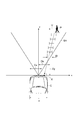
- FIG. 2 is a diagram for explaining parameters used for collision avoidance support.
- FIG. 2 shows changes in the relative positions of the vehicle C and the object P in time series.
- the object P is an object that moves in a direction intersecting the traveling direction of the vehicle C, such as a pedestrian moving across the front of the vehicle C.
- object information including the above-described distance (Dy), lateral position (Dx), and lateral width (W) is defined along with the detection range SA of the sensor.
- the object information is defined using, for example, an x-coordinate where the sensor position is the origin O, the right side of the vehicle C is positive, and a y-coordinate corresponding to the traveling direction of the vehicle C.
- the support execution unit 13 executes vehicle collision avoidance support based on the control of the ECU 20.
- the support execution unit 13 executes at least one of notification support and control support based on the possibility of collision with an object.
- the collision possibility is obtained based on, for example, a collision lateral position and a collision prediction time described later.
- the support execution unit 13 promotes the collision avoidance support between the vehicle and the object as the avoidance margin described later is smaller.
- the driver is notified of the danger of collision and the necessity of collision avoidance operation.
- a vehicle-mounted monitor, a speaker, or a vibrator provided on a seat or a handle is used.
- the control support at least one of braking intervention and steering intervention of the vehicle is executed.
- the control support using a control signal supplied from the ECU 20, at least one of the braking device and the steering device is operated so as to avoid a collision with an object.
- the ECU20 is provided with the collision position estimation part 21, the avoidance margin estimation part 22, and the assistance control part 23.
- FIG. The ECU 20 is composed mainly of a CPU, a ROM, and a RAM, and realizes the functions of the collision position prediction unit 21, the avoidance margin estimation unit 22, and the support control unit 23 through execution of a program by the CPU.
- the collision position prediction unit 21 predicts a collision position (a collision lateral position) in the vehicle width direction between the vehicle and the object.
- the prediction result of the collision position represents the center position of the lateral width of the object, and is predicted based on the relationship between the future or current vehicle position and the future object position.
- the position of the vehicle is predicted based on the current position or the movement state of the vehicle using the vehicle information.
- the position of the object is predicted based on the movement state of the object using the object information.
- the avoidance margin width estimation unit 22 estimates the avoidance margin width in the vehicle width direction in which the collision between the vehicle and the object can be avoided by steering based on the predicted collision position in the vehicle width direction of the vehicle and the object.
- the avoidance margin width is estimated as the margin width on the left side or the right side of the front of the vehicle that is not blocked by the object at the collision prediction position based on the relationship between the collision prediction position, the lateral width of the object, and the vehicle width.
- the avoidance margin is used as an index representing the possibility of collision avoidance by steering, and the larger the value, the higher the possibility of collision avoidance.
- FIG. 2 described above shows the predicted collision position X and the avoidance margin width Ca.
- the speed (lateral speed V) of the object P in the direction orthogonal to the traveling direction of the vehicle C is predicted based on the history of the lateral position Dx of the object P, and the object P as shown by the dotted line in the figure.
- the predicted collision position X is predicted by extrapolating the horizontal position Dx.
- the avoidance margin width Ca is estimated as the margin width on the left side of the front surface of the vehicle C that is not blocked by the object P at the collision predicted position X.
- the support control unit 23 controls the collision avoidance support of the vehicle based on the avoidance margin.
- the assistance control unit 23 controls the assistance so that the collision avoidance assistance is promoted as the avoidance margin width is smaller.
- the collision avoidance support is promoted by at least one of controlling the start timing of the collision avoidance support early and largely controlling the support amount of the collision avoidance support.
- the start timing of the collision avoidance support is controlled earlier, for example, by reducing the determination threshold value of the collision prediction time used for determining the execution of the support.
- the amount of assistance for collision avoidance support is largely controlled, for example, by increasing the level of notification assistance or increasing the control assistance amount for braking intervention or steering intervention.
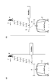
- FIG. 3 is a diagram illustrating an assumed situation of the collision avoidance support process.
- the driver can avoid the collision with the object even when the collision prediction time is small, that is, just before the collision, as the margin width B not blocked by the object is larger. For this reason, in the above processing, the collision avoidance support is suppressed as the margin width B is large so that the steering avoidance by the driver and the control support by the collision avoidance support do not interfere with each other.
- the margin width B may occur on both the front left side and the front right side of the vehicle C with respect to the vehicle width center O.
- the margin width becomes larger regardless of the moving direction of the object P (in the example shown in FIG. 3B, the direction approaching the object P, that is, the opposite side of the moving direction of the object P).
- the margin width B is calculated at the front right side of the vehicle C).
- the driver usually moves away from the object P in order to avoid collision with the object when steering is avoided, that is, the moving direction side of the object P (side of the arrow S). Steer to. For this reason, it is desirable to perform collision avoidance support based on the margin width on the moving direction side of the object P on the steering direction side.
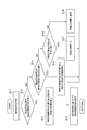
- FIG. 4 is a flowchart showing the operation of the collision avoidance assistance device and the collision avoidance assistance method.
- the collision avoidance assistance device repeatedly executes the processing shown in FIG. 4 at predetermined processing cycles.
- the process illustrated in FIG. 4 is executed, for example, when the object is moving in a direction that intersects the traveling direction of the vehicle, in particular, a direction that is orthogonal.
- the movement status of the object is determined based on the history of object information.
- the collision position prediction unit 21 predicts the collision position based on the relationship between the future or current vehicle position and the future object position (step S11).
- the avoidance margin width estimation unit 22 estimates the avoidance margin width based on the collision position prediction result (collision prediction position). As described below with reference to FIG. 5, the avoidance margin width is estimated by a different method depending on the relationship between the predicted collision position, the lateral width of the object, and the vehicle width.
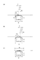
- FIG. 5 is a diagram illustrating the relationship between the predicted collision position and the avoidance margin width.
- the avoidance margin estimation unit 22 determines whether or not the predicted collision position is closer to the moving direction of the object than the center of the vehicle width (S12).
- the predicted collision position X is on the left side of the vehicle width center O.
- the object P is moving rightward, it is determined whether or not the predicted collision position X is on the right side of the vehicle width center O.
- condition of S12 is satisfied by satisfying conditional expressions (1a) and (1b).
- Conditional expression (1a) indicates a condition in which a collision with an object occurs
- conditional expression (1b) indicates a condition in which the predicted collision position is closer to the moving direction of the object than the center of the vehicle width.
- X represents the predicted collision position
- W represents the lateral width of the object
- w represents the vehicle width
- V represents the lateral velocity of the object
- C represents the margin for avoidance.
- the lateral velocity of the object is negative when the object is moving in the left direction.
- the vehicle width w may be a value that considers a margin for the vehicle width instead of the vehicle width.
- X ⁇ W / 2 ⁇ w / 2 (1a) (X ⁇ 0 and V ⁇ 0) or (X ⁇ 0 and V ⁇ 0) (1b)
- the avoidance margin estimation unit 22 estimates the avoidance margin using the estimation formula (2) (S13).
- C w / 2 ⁇
- the avoidance margin estimation unit 22 determines whether or not the predicted collision position is on the opposite side of the moving direction of the object from the center of the vehicle width (S14).
- the predicted collision position X is on the right side of the vehicle width center O.
- the object P is moving leftward, it is determined whether or not the predicted collision position X is on the right side of the vehicle width center O.
- conditional expression (3a) indicates a condition in which a collision with an object occurs
- conditional expression (3b) indicates a condition in which the predicted collision position is on the opposite side of the moving direction of the object from the center of the vehicle width.
- the avoidance margin estimation unit 22 estimates the avoidance margin using the estimation formula (4) (S15).
- C w / 2 +
- the avoidance margin estimation unit 22 determines whether or not the object completely blocks the front surface of the vehicle (S16).
- S16 is satisfied by satisfying conditional expressions (5a) and (5b).
- the avoidance margin estimation unit 22 estimates an avoidance margin equal to the vehicle width as shown in the estimation formula (7) (S18). In this case, it means that there is no collision with the object.
- C w (7)
- the support execution unit 13 performs collision avoidance support based on the avoidance margin (S19).
- FIG. 6 is a diagram showing the situation of the collision avoidance support process shown in FIG.
- FIG. 6 shows the situation of the collision avoidance support process shown in FIG. 4 in comparison with FIG.
- the collision avoidance assistance is promoted as the avoidance margin width Ca estimated based on the predicted collision position X in the vehicle width direction is smaller. Therefore, in the situation shown in FIG. 6A, the collision avoidance support is started at an earlier timing than the situation shown in FIG. 3A based on the avoidance margin width Ca estimated based on the predicted collision position X. Will be.
- the collision avoidance assistance is executed based on the margin width on the side away from the object P, that is, the moving direction of the object P (the direction of the lateral velocity V) with reference to the vehicle width center O. Therefore, in the situation shown in FIG. 6B, unlike the situation shown in FIG. 3B, the avoidance margin width Ca on the moving direction side of the object P that is on the steering direction side (the front left side of the vehicle C). Based on this, appropriate collision avoidance assistance is executed.
- the collision avoidance support is promoted by accelerating the start timing of the collision avoidance support.
- the level of notification support may be increased or the control support amount may be increased.
- the collision avoidance assistance device As described above, according to the collision avoidance assistance device according to the embodiment of the present invention, the collision avoidance assistance is promoted as the avoidance margin width estimated based on the predicted collision position in the vehicle width direction is smaller. Therefore, when there is a high possibility that the object will block the course immediately before the collision, the collision avoidance support becomes difficult to be suppressed, and the uncomfortable feeling given to the driver with respect to the collision avoidance support can be reduced.
- collision avoidance assistance is executed based on the margin width on the object moving direction side with respect to the center of the vehicle width.
- the driver usually steers in the direction away from the object, that is, in the moving direction side of the object, in order to avoid collision with the object when steering is avoided. Therefore, the collision avoidance support can be appropriately executed based on the avoidance margin width on the moving direction side of the object on the steering direction side.
- SYMBOLS 11 Vehicle information acquisition part, 12 ... Object information acquisition part, 13 ... Support execution part, 20 ... ECU, 21 ... Collision position prediction part, 22 ... Avoidance margin width estimation part, 23 ... Support control part.
Landscapes
- Engineering & Computer Science (AREA)
- Transportation (AREA)
- Mechanical Engineering (AREA)
- Chemical & Material Sciences (AREA)
- Combustion & Propulsion (AREA)
- Automation & Control Theory (AREA)
- Physics & Mathematics (AREA)
- Mathematical Physics (AREA)
- Traffic Control Systems (AREA)
Abstract
衝突回避支援装置は、車両と物体の車幅方向における衝突予測位置に基づいて、車両と物体の衝突を操舵により回避可能な車幅方向における回避余裕幅を推定する回避余裕幅推定部と、回避余裕幅が小さいほど車両と物体の衝突回避支援を促進する支援実行部とを備える。
Description
本発明は、車両と物体の衝突回避を支援する衝突回避支援装置及び衝突回避支援方法に関する。
従来、衝突回避支援装置及び衝突回避支援方法としては、例えば特開2008-132867号公報に記載されるように、先行車両などの障害物が車両の進路を塞ぐ程度が小さいほど衝突回避支援の開始タイミングを遅らせる装置及び方法が知られている。このような装置は、安全性を損なうことなく、衝突回避支援の実行に対して運転者に与える違和感を低減させようとするものである。
ところで、車両前方を横断する歩行者など、車両の進行方向と交差する方向に移動する物体との衝突回避を支援する際には、物体が車両の進路を塞いでいない状況が継続することが想定される。すると、衝突直前に障害物が車両の進路を塞ぐ可能性が高くても衝突回避支援が抑制されることになり、衝突回避支援の実行に対して運転者に違和感を与えることになる。
そこで、本発明は、衝突回避支援の実行に対して運転者に与える違和感を低減できる衝突回避支援装置及び衝突回避支援方法を提供しようとするものである。
本発明に係る衝突回避支援装置は、車両と物体の車幅方向における衝突予測位置に基づいて、車両と物体の衝突を操舵により回避可能な車幅方向における回避余裕幅を推定する回避余裕幅推定部と、回避余裕幅が小さいほど車両と物体の衝突回避支援を促進する支援実行部とを備える。
これにより、車幅方向における衝突予測位置に基づいて推定される回避余裕幅が小さいほど衝突回避支援が促進される。よって、物体が衝突直前に進路を塞ぐ可能性が高い場合には、衝突回避支援が抑制され難くなり、衝突回避支援に対して運転者に与える違和感を低減できる。ここで、回避余裕幅は、衝突予測位置において物体により塞がれていない車両の前面左側又は前面右側の余裕幅として推定されてもよい。
また、回避余裕幅は、車幅中央を基準として物体の移動方向の側の余裕幅として推定されてもよい。これにより、物体の移動方向の側の余裕幅に基づいて衝突回避支援が実行される。ここで、運転者は、通常、操舵回避に際して物体との衝突を回避するために物体から遠ざかる方向、つまり物体の移動方向の側へ操舵を行う。よって、操舵方向の側となる物体の移動方向の側の回避余裕幅に基づいて衝突回避支援を適切に実行できる。
また、衝突予測位置は、将来又は現在における車両の位置と将来における物体の位置との関係に基づいて推定されてもよい。
また、車両の位置は、車両の現在位置又は移動状況に基づいて予測され、物体の位置は、物体の移動状況に基づいて予測されてもよい。
また、衝突回避支援は、衝突回避支援の開始タイミングを早くすること、及び衝突回避支援の支援量を大きくすることの少なくとも一方により促進されてもよい。
また、衝突回避支援は、車両の制動介入及び操舵介入の少なくとも一方により実行されてもよい。
また、衝突回避支援装置は、車両と車両前方を横断して移動する物体との衝突回避を支援してもよい。
本発明に係る衝突回避支援方法は、車両と物体の車幅方向における衝突予測位置に基づいて、車両と物体の衝突を操舵により回避可能な車幅方向における回避余裕幅を推定する回避余裕幅推定ステップと、回避余裕幅が小さいほど車両と物体の衝突回避支援を促進する支援実行ステップとを含む。
本発明によれば、衝突回避支援の実行に対して運転者に与える違和感を低減できる衝突回避支援装置及び衝突回避支援方法を提供することができる。
以下、添付図面を参照して、本発明の実施形態を詳細に説明する。なお、図面の説明において同一の要素には同一の符号を付し、重複する説明を省略する。
まず、図1及び図2を参照して、本発明の実施形態に係る衝突回避支援装置の構成について説明する。図1は、本発明の実施形態に係る衝突回避支援装置の構成を示すブロック図である。
衝突回避支援装置は、車両に搭載され、車両と物体の衝突回避支援を行う装置であり、プリクラッシュセーフティ(PCS;登録商標)システムとも称される。図1に示すように、衝突回避支援装置は、車両情報取得部11、物体情報取得部12、支援実行部13及びECU(Electronic Control Unit)20を備えている。
車両情報取得部11は、車両の位置及び移動状況を示す車両情報を取得する。車両情報取得部11には、例えば、GPSセンサ、車輪速センサ、加速度センサ、操舵角センサ、ヨーレートセンサが用いられる。車両情報取得部11は、例えば、車両の現在位置、進行方向、速度、加速度、操舵角、ヨーレートを車両情報として取得してECU20に供給する。
物体情報取得部12は、車両前方に存在する物体の位置及び移動状況を示す物体情報を取得する。物体とは、例えば、対向車、先行車、自転車、歩行者など車両の走行を妨げ得る障害物である。物体情報取得部12には、例えば、ミリ波又はレーザによるレーダセンサ、カメラセンサが用いられる。物体情報取得部12は、例えば、物体までの距離、物体の横位置及び横幅を物体情報として取得してECU20に供給する。物体情報取得部12は、特に、ステレオカメラセンサ単独、又はレーダセンサとステレオカメラセンサの組合せとして構成される。
例えば、レーダセンサは、車両前方に送信され物体から反射されて受信されるセンサ波の送受信結果に基づいて物体情報を取得する。物体までの距離は、車両の進行方向におけるセンサから物体までの距離を表し、センサ波が送信され物体から反射されて受信されるまでの時間に基づいて求められる。物体の横位置は、車両の進行方向と直交する方向における車両中央から物体までの距離を表し、物体から反射されて受信されるセンサ波の受信角度に基づいて求められる。
また、ステレオカメラセンサは、左右カメラの画像データにおける物体の見え方のずれに基づいて、三角測量の原理により物体情報を取得する。ステレオカメラセンサでは、物体までの距離及び物体の横位置とともに物体の横幅が取得される。なお、モノカメラセンサは、例えば、前方車両のナンバープレートの大きさ及び位置に基づいて、又は物体の接地位置に基づいて物体情報を取得する。
図2は、衝突回避支援に用いるパラメータを説明する図である。図2には、車両Cと物体Pの相対位置の変化が時系列的に示されている。物体Pは、車両C前方を横断して移動する歩行者など、車両Cの進行方向と交差する方向に移動する物体である。図2には、センサの検知範囲SAとともに、前述した距離(Dy)、横位置(Dx)及び横幅(W)からなる物体情報が定義されている。物体情報は、例えば、センサの位置を原点O、車両Cの右側を正とするx座標、及び車両Cの進行方向に相当するy座標を用いて定義されている。
図1の説明に戻って、支援実行部13は、ECU20の制御に基づいて車両の衝突回避支援を実行する。支援実行部13は、物体との衝突可能性に基づいて報知支援及び制御支援の少なくとも一方を実行する。衝突可能性は、例えば、後述する衝突横位置、衝突予測時間に基づいて求められる。ここで、支援実行部13は、後述する回避余裕幅が小さいほど車両と物体の衝突回避支援を促進する。
報知支援では、例えば、衝突の危険性、衝突回避操作の必要性が運転者に報知される。報知支援には、例えば、車載モニタ、スピーカ、又はシート若しくはハンドルに設けられたバイブレータが用いられる。制御支援では、車両の制動介入及び操舵介入の少なくとも一方が実行される。制御支援では、ECU20から供給される制御信号を用いて、物体との衝突を回避するように制動装置及び操舵装置の少なくとも一方が作動される。
ECU20は、衝突位置予測部21、回避余裕幅推定部22及び支援制御部23を備えている。ECU20は、CPU、ROM、RAMを主体として構成され、CPUによるプログラムの実行を通じて、衝突位置予測部21、回避余裕幅推定部22及び支援制御部23の機能を実現する。
衝突位置予測部21は、車両と物体の車幅方向における衝突位置(衝突横位置)を予測する。衝突位置の予測結果(衝突予測位置)は、物体の横幅の中心位置を表しており、将来又は現在における車両の位置と将来における物体の位置との関係に基づいて予測される。車両の位置は、車両情報を用いて、車両の現在位置又は移動状況に基づいて予測される。物体の位置は、物体情報を用いて、物体の移動状況に基づいて予測される。
回避余裕幅推定部22は、車両と物体の車幅方向における衝突予測位置に基づいて、車両と物体の衝突を操舵により回避可能な車幅方向における回避余裕幅を推定する。回避余裕幅は、衝突予測位置、物体の横幅及び車幅の関係に基づいて、衝突予測位置において物体により塞がれていない車両の前面左側又は右側の余裕幅として推定される。回避余裕幅は、操舵による衝突回避の可能性を表す指標として用いられ、その値が大きいほど衝突回避の可能性が高いことを意味する。
前述した図2には、衝突予測位置X及び回避余裕幅Caが示されている。例えば、図2では、物体Pの横位置Dxの履歴に基づいて車両Cの進行方向と直交する方向における物体Pの速度(横速度V)を予測し、図中に点線で示すように物体Pの横位置Dxを外挿することにより衝突予測位置Xが予測されている。そして、衝突予測位置Xにおいて物体Pにより塞がれていない車両Cの前面左側の余裕幅として回避余裕幅Caが推定されている。
図1の説明に戻って、支援制御部23は、回避余裕幅に基づいて車両の衝突回避支援を制御する。ここで、支援制御部23は、回避余裕幅が小さいほど衝突回避支援が促進されるように支援を制御する。衝突回避支援は、衝突回避支援の開始タイミングを早く制御すること及び衝突回避支援の支援量を大きく制御することの少なくとも一方により促進される。衝突回避支援の開始タイミングは、例えば、支援の実行判定に用いる衝突予測時間の判定閾値を小さくすることにより早く制御される。また、衝突回避支援の支援量は、例えば、報知支援のレベルを上げたり、制動介入又は操舵介入の制御支援量を大きくしたりすることにより大きく制御される。
つぎに、図1に示す衝突回避支援装置の動作について説明する前に、図3を参照して、想定される衝突回避支援処理の状況について説明する。図3は、衝突回避支援処理の想定される状況を示す図である。
衝突回避に際して、運転者は、物体により塞がれていない余裕幅Bが大きいほど小さな衝突予測時間でも、つまり衝突直前でも物体との衝突を操舵回避できる。このため、上記処理では、運転者による操舵回避と、衝突回避支援による制御支援とが干渉しないように、余裕幅Bが大きいほど衝突回避支援を抑制される。
しかし、図3(a)に示すように、車両C前方を横断して移動する物体Pとの衝突回避を支援する際には、物体Pが車両Cの進路を塞いでいない状況、つまり余裕幅Bが大きい状態が継続する。すると、物体Pの横位置に基づいて衝突回避支援の開始を判定する上記処理では、衝突直前に物体Pが車両Cの進路を塞ぐ可能性が高い場合でも、衝突直前まで衝突回避支援が開始されないことになる。
また、余裕幅Bは、車両Cと物体Pの位置関係によっては、車幅中央Oを基準として車両Cの前面左側と前面右側の両方に生じる場合がある。しかし、上記処理では、物体Pの移動方向とは関係なく余裕幅が大きくなる側(図3(b)に示す例では、物体Pに近づく方向、つまり物体Pの移動方向とは反対側となる車両Cの前面右側)で余裕幅Bが算出される。
一方、図3(b)に示すように、運転者は、通常、操舵回避に際して物体との衝突を回避するために物体Pから遠ざかる方向、つまり物体Pの移動方向の側(矢印Sの側)へ操舵を行う。このため、操舵方向の側となる物体Pの移動方向の側の余裕幅に基づいて衝突回避支援を実行することが望まれる。
つぎに、図4から図6を参照して、図1に示す衝突回避支援装置の動作及び衝突回避支援方法について説明する。図4は、衝突回避支援装置の動作及び衝突回避支援方法を示すフローチャートである。
衝突回避支援装置は、図4に示す処理を所定の処理周期毎に繰り返し実行する。図4に示す処理は、例えば、物体が車両の進行方向と交差する方向、特に直交する方向に移動している場合に実行される。物体の移動状況については、物体情報の履歴に基づいて判定される。
図4に示すように、衝突位置予測部21は、将来又は現在における車両の位置と将来における物体の位置との関係に基づいて衝突位置を予測する(ステップS11)。回避余裕幅推定部22は、衝突位置の予測結果(衝突予測位置)に基づいて回避余裕幅を推定する。回避余裕幅は、図5を参照して以下で述べるように、衝突予測位置、物体の横幅及び車幅の関係に応じて異なる方法で推定される。図5は、衝突予測位置と回避余裕幅の関係を示す図である。
回避余裕幅推定部22は、衝突予測位置が車幅中央よりも物体の移動方向の側であるか否かを判定する(S12)。ここでは、例えば図5(a)に示すように、物体Pが左方向へ移動している場合には、衝突予測位置Xが車幅中央Oよりも左側であるか否かを判定する。もちろん、物体Pが右方向へ移動している場合には、衝突予測位置Xが車幅中央Oよりも右側であるか否かを判定することになる。
S12の条件は、条件式(1a)及び(1b)の成立により満たされる。条件式(1a)は、物体との衝突が生じる条件を示し、条件式(1b)は、衝突予測位置が車幅中央よりも物体の移動方向の側となる条件を示している。
ここで、式中の符号は、Xが衝突予測位置、Wが物体の横幅、wが車幅、Vが物体の横速度、Cが回避余裕幅を表している。なお、物体の横速度は、物体が左方向へ移動している場合に負となる。また、車幅wとしては、車幅に代えて車幅に余裕代を考慮した値としてもよい。
|X|-W/2≦w/2 …(1a)
(X≧0 かつ V≧0)又は(X<0 かつ V<0) …(1b)
|X|-W/2≦w/2 …(1a)
(X≧0 かつ V≧0)又は(X<0 かつ V<0) …(1b)
そして、S12の条件に該当する場合、回避余裕幅推定部22は、推定式(2)により回避余裕幅を推定する(S13)。
C=w/2-|X|-W/2 …(2)
C=w/2-|X|-W/2 …(2)
S12の条件に該当しない場合、回避余裕幅推定部22は、衝突予測位置が車幅中央よりも物体の移動方向と反対側であるか否かを判定する(S14)。ここでは、例えば図5(b)に示すように、物体Pが左方向へ移動している場合には、衝突予測位置Xが車幅中央Oよりも右側であるか否かを判定する。もちろん、物体Pが左方向へ移動している場合には、衝突予測位置Xが車幅中央Oよりも右側であるか否かを判定することになる。
S14の条件は、条件式(3a)及び(3b)の成立により満たされる。条件式(3a)は、物体との衝突が生じる条件を示し、条件式(3b)は、衝突予測位置が車幅中央よりも物体の移動方向と反対側となる条件を示している。
|X|-W/2≦w/2 …(3a)
(X≧0 かつ V<0)又は(X<0 かつ V≧0) …(3b)
|X|-W/2≦w/2 …(3a)
(X≧0 かつ V<0)又は(X<0 かつ V≧0) …(3b)
そして、S14の条件に該当する場合、回避余裕幅推定部22は、推定式(4)により回避余裕幅を推定する(S15)。
C=w/2+|X|-W/2 …(4)
C=w/2+|X|-W/2 …(4)
S14の条件に該当しない場合、回避余裕幅推定部22は、物体が車両の前面を完全に塞ぐか否かを判定する(S16)。ここでは、例えば図5(c)に示すように、物体Pが車両Cの前面を完全に塞ぐか否かを判定することになる。S16の条件は、条件式(5a)及び(5b)の成立により満たされる。
X+W/2≧w/2 …(5a)
X-W/2≦-w/2 …(5b)
X+W/2≧w/2 …(5a)
X-W/2≦-w/2 …(5b)
そして、S16の条件に該当する場合、回避余裕幅推定部22は、推定式(6)のとおり回避余裕幅を0と推定する(S17)。この場合、物体との衝突を操舵回避できる余裕幅がないことを意味する。
C=0 …(6)
C=0 …(6)
S16の条件に該当しない場合、回避余裕幅推定部22は、推定式(7)のとおり車幅に等しい回避余裕幅を推定する(S18)。この場合、物体との衝突が生じないことを意味する。
C=w …(7)
C=w …(7)
S13、S15、S17又はS18にて回避余裕幅を推定すると、支援実行部13は、回避余裕幅に基づいて衝突回避支援を実行する(S19)。
図6は、図4に示す衝突回避支援処理の状況を示す図である。図6には、図4に示す衝突回避支援処理の状況が図3と対比して示されている。前述したように、車幅方向における衝突予測位置Xに基づいて推定される回避余裕幅Caが小さいほど衝突回避支援が促進される。よって、図6(a)に示す状況では、衝突予測位置Xに基づいて推定される回避余裕幅Caに基づいて、図3(a)に示した状況よりも早いタイミングで衝突回避支援が開始されることになる。
また、車幅中央Oを基準として、物体Pから遠ざかる方向、つまり物体Pの移動方向(横速度Vの方向)の側の余裕幅に基づいて衝突回避支援が実行される。よって、図6(b)に示す状況では、図3(b)に示した状況とは異なり、操舵方向の側となる物体Pの移動方向の側(車両Cの前面左側)の回避余裕幅Caに基づいて適切な衝突回避支援が実行されることになる。
また、回避余裕幅Caが大きい状況(a)よりも、回避余裕幅Caが小さい状況(b)では、衝突回避支援の開始タイミングを早くすることにより衝突回避支援が促進されている。なお、これに代えて又は加えて、報知支援のレベルを高くしたり、制御支援量を大きくしたりしてもよい。
以上説明したように、本発明の実施形態に係る衝突回避支援装置によれば、車幅方向における衝突予測位置に基づいて推定される回避余裕幅が小さいほど衝突回避支援が促進される。よって、物体が衝突直前に進路を塞ぐ可能性が高い場合には、衝突回避支援が抑制され難くなり、衝突回避支援に対して運転者に与える違和感を低減できる。
また、車幅中央を基準として物体の移動方向の側の余裕幅に基づいて衝突回避支援が実行される。ここで、運転者は、通常、操舵回避に際して物体との衝突を回避するために物体から遠ざかる方向、つまり物体の移動方向の側へ操舵を行う。よって、操舵方向の側となる物体の移動方向の側の回避余裕幅に基づいて衝突回避支援を適切に実行できる。
なお、前述した実施形態は、本発明に係る衝突回避支援装置及び衝突回避支援方法の最良な実施形態を説明したものであり、本発明に係る衝突回避支援装置及び衝突回避支援方法は、本実施形態に記載したものに限定されるものではない。本発明に係る衝突回避支援装置及び衝突回避支援方法は、各請求項に記載した発明の要旨を逸脱しない範囲で本実施形態に係る衝突回避支援装置及び衝突回避支援方法を変形し、または他のものに適用したものであってもよい。
11…車両情報取得部、12…物体情報取得部、13…支援実行部、20…ECU、21…衝突位置予測部、22…回避余裕幅推定部、23…支援制御部。
Claims (9)
- 車両と物体の車幅方向における衝突予測位置に基づいて、前記車両と前記物体の衝突を操舵により回避可能な車幅方向における回避余裕幅を推定する回避余裕幅推定部と、
前記回避余裕幅が小さいほど前記車両と前記物体の衝突回避支援を促進する支援実行部と、
を備える衝突回避支援装置。 - 前記回避余裕幅は、前記衝突予測位置において前記物体により塞がれていない前記車両の前面左側又は前面右側の余裕幅として推定される、請求項1に記載の衝突回避支援装置。
- 前記回避余裕幅は、車幅中央を基準として前記物体の移動方向の側の余裕幅として推定される、請求項1又は2に記載の衝突回避支援装置。
- 前記衝突予測位置は、将来又は現在における前記車両の位置と将来における前記物体の位置との関係に基づいて推定される、請求項1~3のいずれか一項に記載の衝突回避支援装置。
- 前記車両の位置は、前記車両の現在位置又は移動状況に基づいて予測され、前記物体の位置は、前記物体の移動状況に基づいて予測される、請求項4に記載の衝突回避支援装置。
- 前記衝突回避支援は、前記衝突回避支援の開始タイミングを早くすること、及び前記衝突回避支援の支援量を大きくすることの少なくとも一方により促進される、請求項1~5のいずれか一項に記載の衝突回避支援装置。
- 前記衝突回避支援は、車両の制動介入及び操舵介入の少なくとも一方により実行される、請求項1~6のいずれか一項に記載の衝突回避支援装置。
- 前記物体は、前記車両前方を横断して移動する物体である、請求項1~7のいずれか一項に記載の衝突回避支援装置。
- 車両と物体の車幅方向における衝突予測位置に基づいて、前記車両と前記物体の衝突を操舵により回避可能な車幅方向における回避余裕幅を推定する回避余裕幅推定ステップと、
前記回避余裕幅が小さいほど前記車両と前記物体の衝突回避支援を促進する支援実行ステップと、
を含む衝突回避支援方法。
Priority Applications (1)
| Application Number | Priority Date | Filing Date | Title |
|---|---|---|---|
| PCT/JP2012/072482 WO2014037997A1 (ja) | 2012-09-04 | 2012-09-04 | 衝突回避支援装置及び衝突回避支援方法 |
Applications Claiming Priority (1)
| Application Number | Priority Date | Filing Date | Title |
|---|---|---|---|
| PCT/JP2012/072482 WO2014037997A1 (ja) | 2012-09-04 | 2012-09-04 | 衝突回避支援装置及び衝突回避支援方法 |
Publications (1)
| Publication Number | Publication Date |
|---|---|
| WO2014037997A1 true WO2014037997A1 (ja) | 2014-03-13 |
Family
ID=50236650
Family Applications (1)
| Application Number | Title | Priority Date | Filing Date |
|---|---|---|---|
| PCT/JP2012/072482 Ceased WO2014037997A1 (ja) | 2012-09-04 | 2012-09-04 | 衝突回避支援装置及び衝突回避支援方法 |
Country Status (1)
| Country | Link |
|---|---|
| WO (1) | WO2014037997A1 (ja) |
Cited By (2)
| Publication number | Priority date | Publication date | Assignee | Title |
|---|---|---|---|---|
| WO2016124368A1 (de) * | 2015-02-02 | 2016-08-11 | Robert Bosch Gmbh | Verfahren zum betrieb eines fahrzeugs, computerprogramm, maschinenlesbares speichermedium, elektronische steuereinheit |
| CN112154493A (zh) * | 2018-05-21 | 2020-12-29 | 株式会社电装 | 行驶辅助装置 |
Citations (5)
| Publication number | Priority date | Publication date | Assignee | Title |
|---|---|---|---|---|
| JP2002504452A (ja) * | 1998-02-18 | 2002-02-12 | ダイムラークライスラー・アクチェンゲゼルシャフト | 車両の前方に位置する障害物との車両の衝突を防止するための方法及び制動装置 |
| JP2006099715A (ja) * | 2004-09-06 | 2006-04-13 | Daihatsu Motor Co Ltd | 衝突予測方法及び衝突予測装置 |
| JP2008132867A (ja) * | 2006-11-28 | 2008-06-12 | Hitachi Ltd | 衝突回避支援装置及びそれを搭載した車両 |
| JP2009020577A (ja) * | 2007-07-10 | 2009-01-29 | Omron Corp | 検出装置および方法、並びに、プログラム |
| JP2010036856A (ja) * | 2008-08-08 | 2010-02-18 | Nissan Motor Co Ltd | 車両用走行支援装置および車両用走行支援方法 |
-
2012
- 2012-09-04 WO PCT/JP2012/072482 patent/WO2014037997A1/ja not_active Ceased
Patent Citations (5)
| Publication number | Priority date | Publication date | Assignee | Title |
|---|---|---|---|---|
| JP2002504452A (ja) * | 1998-02-18 | 2002-02-12 | ダイムラークライスラー・アクチェンゲゼルシャフト | 車両の前方に位置する障害物との車両の衝突を防止するための方法及び制動装置 |
| JP2006099715A (ja) * | 2004-09-06 | 2006-04-13 | Daihatsu Motor Co Ltd | 衝突予測方法及び衝突予測装置 |
| JP2008132867A (ja) * | 2006-11-28 | 2008-06-12 | Hitachi Ltd | 衝突回避支援装置及びそれを搭載した車両 |
| JP2009020577A (ja) * | 2007-07-10 | 2009-01-29 | Omron Corp | 検出装置および方法、並びに、プログラム |
| JP2010036856A (ja) * | 2008-08-08 | 2010-02-18 | Nissan Motor Co Ltd | 車両用走行支援装置および車両用走行支援方法 |
Cited By (3)
| Publication number | Priority date | Publication date | Assignee | Title |
|---|---|---|---|---|
| WO2016124368A1 (de) * | 2015-02-02 | 2016-08-11 | Robert Bosch Gmbh | Verfahren zum betrieb eines fahrzeugs, computerprogramm, maschinenlesbares speichermedium, elektronische steuereinheit |
| CN112154493A (zh) * | 2018-05-21 | 2020-12-29 | 株式会社电装 | 行驶辅助装置 |
| CN112154493B (zh) * | 2018-05-21 | 2022-05-10 | 株式会社电装 | 行驶辅助装置 |
Similar Documents
| Publication | Publication Date | Title |
|---|---|---|
| JP5880717B2 (ja) | 衝突回避支援装置及び衝突回避支援方法 | |
| JP6530705B2 (ja) | 運転支援装置及び運転支援方法 | |
| JP6569523B2 (ja) | 走行支援装置 | |
| JP6515823B2 (ja) | 車線変更支援装置 | |
| JP6729282B2 (ja) | 車両制御装置 | |
| CN108622085B (zh) | 碰撞避免装置 | |
| JP5949961B2 (ja) | 運転支援装置 | |
| JP6047891B2 (ja) | 車両用走行制御装置 | |
| JP5900293B2 (ja) | 衝突回避支援装置及び衝突回避支援方法 | |
| JP5397231B2 (ja) | リスク回避支援装置 | |
| JP2019093934A (ja) | 車両の制動支援装置、制御装置及び制動支援方法 | |
| JP2017117344A (ja) | 走行支援装置 | |
| JP6443292B2 (ja) | 運転支援装置、及び運転支援方法 | |
| JP6504078B2 (ja) | 衝突予測装置 | |
| JP6740970B2 (ja) | 走行支援装置 | |
| CN115214762B (zh) | 车辆控制系统和车辆控制方法 | |
| JP2006298294A (ja) | 車両の走行安全装置 | |
| JP5328738B2 (ja) | 後側方操舵支援技術 | |
| JP2016011088A (ja) | 車両制御装置、車両制御方法、及び、車両制御用プログラム | |
| JP6241673B2 (ja) | 車両の制御装置 | |
| WO2014037997A1 (ja) | 衝突回避支援装置及び衝突回避支援方法 | |
| WO2014068668A1 (ja) | 衝突回避支援装置及び衝突回避支援方法 | |
| JP6222432B2 (ja) | 車両用走行制御装置 | |
| JP2025174875A (ja) | 車両制御方法、車両制御システム | |
| JP2025091787A (ja) | 車両制御装置、車両制御方法及び車両制御プログラム |
Legal Events
| Date | Code | Title | Description |
|---|---|---|---|
| 121 | Ep: the epo has been informed by wipo that ep was designated in this application |
Ref document number: 12884082 Country of ref document: EP Kind code of ref document: A1 |
|
| NENP | Non-entry into the national phase |
Ref country code: DE |
|
| 122 | Ep: pct application non-entry in european phase |
Ref document number: 12884082 Country of ref document: EP Kind code of ref document: A1 |
|
| NENP | Non-entry into the national phase |
Ref country code: JP |