WO2014037973A1 - 磁気記録媒体読取装置 - Google Patents
磁気記録媒体読取装置 Download PDFInfo
- Publication number
- WO2014037973A1 WO2014037973A1 PCT/JP2012/005622 JP2012005622W WO2014037973A1 WO 2014037973 A1 WO2014037973 A1 WO 2014037973A1 JP 2012005622 W JP2012005622 W JP 2012005622W WO 2014037973 A1 WO2014037973 A1 WO 2014037973A1
- Authority
- WO
- WIPO (PCT)
- Prior art keywords
- magnetic
- recording medium
- magnetic field
- magnetic recording
- magnetic head
- Prior art date
- Legal status (The legal status is an assumption and is not a legal conclusion. Google has not performed a legal analysis and makes no representation as to the accuracy of the status listed.)
- Ceased
Links
Images











Classifications
-
- G—PHYSICS
- G07—CHECKING-DEVICES
- G07F—COIN-FREED OR LIKE APPARATUS
- G07F19/00—Complete banking systems; Coded card-freed arrangements adapted for dispensing or receiving monies or the like and posting such transactions to existing accounts, e.g. automatic teller machines
- G07F19/20—Automatic teller machines [ATMs]
- G07F19/205—Housing aspects of ATMs
- G07F19/2055—Anti-skimming aspects at ATMs
-
- G—PHYSICS
- G06—COMPUTING OR CALCULATING; COUNTING
- G06K—GRAPHICAL DATA READING; PRESENTATION OF DATA; RECORD CARRIERS; HANDLING RECORD CARRIERS
- G06K13/00—Conveying record carriers from one station to another, e.g. from stack to punching mechanism
- G06K13/02—Conveying record carriers from one station to another, e.g. from stack to punching mechanism the record carrier having longitudinal dimension comparable with transverse dimension, e.g. punched card
- G06K13/08—Feeding or discharging cards
-
- G—PHYSICS
- G06—COMPUTING OR CALCULATING; COUNTING
- G06K—GRAPHICAL DATA READING; PRESENTATION OF DATA; RECORD CARRIERS; HANDLING RECORD CARRIERS
- G06K7/00—Methods or arrangements for sensing record carriers, e.g. for reading patterns
- G06K7/08—Methods or arrangements for sensing record carriers, e.g. for reading patterns by means detecting the change of an electrostatic or magnetic field, e.g. by detecting change of capacitance between electrodes
- G06K7/082—Methods or arrangements for sensing record carriers, e.g. for reading patterns by means detecting the change of an electrostatic or magnetic field, e.g. by detecting change of capacitance between electrodes using inductive or magnetic sensors
- G06K7/083—Methods or arrangements for sensing record carriers, e.g. for reading patterns by means detecting the change of an electrostatic or magnetic field, e.g. by detecting change of capacitance between electrodes using inductive or magnetic sensors inductive
- G06K7/084—Methods or arrangements for sensing record carriers, e.g. for reading patterns by means detecting the change of an electrostatic or magnetic field, e.g. by detecting change of capacitance between electrodes using inductive or magnetic sensors inductive sensing magnetic material by relative movement detecting flux changes without altering its magnetised state
Definitions
- the present invention relates to an apparatus for reading data recorded on a magnetic recording medium, and more particularly to a magnetic recording medium reading apparatus having a function of preventing unauthorized acquisition of data.
- a transaction processing apparatus such as an ATM (Automated Teller Machine) or a CD (Cash Dispenser) is equipped with a card reader for reading a magnetic card.
- ATM Automated Teller Machine
- CD Credit Dispenser
- a transaction processing apparatus such as an ATM (Automated Teller Machine) or a CD (Cash Dispenser) is equipped with a card reader for reading a magnetic card.
- a crime called skimming has been generated, in which data recorded on a magnetic stripe of the card is illegally acquired.
- an unauthorized reader equipped with a magnetic head is placed near the card insertion slot of a card reader provided in an ATM or CD, and is inserted into the card reader by the magnetic head of this unauthorized reader.
- Patent Document 1 listed below describes a card reader in which an interfering magnetic field generator is provided in the vicinity of a card insertion slot.
- the disturbing magnetic field generator generates a disturbing magnetic field in the outer area of the card insertion slot. For this reason, even if an unauthorized reader is attached to the outside of the card insertion slot, the data read by the device is affected by the disturbing magnetic field and becomes data different from the original data recorded on the card. This can prevent unauthorized acquisition of card data.
- Patent Document 2 listed below describes a card reader in which a loop antenna for generating a disturbing magnetic field is provided around a card insertion slot.
- the antenna surface of the loop antenna is parallel to the front of the card slot.
- a disturbing magnetic field is generated in the outer area of the card insertion slot, so that even if an unauthorized reader is attached to the outside of the card insertion slot, unauthorized acquisition of card data is prevented. Can.
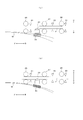
- FIG. 20 shows an example of a card reader provided with a disturbing magnetic field generator.
- a card slot unit 24 is provided on the front of the case 100 of the card reader 1.
- the card insertion slot unit 24 is formed with an insertion slot 22 into which the magnetic card 21 is inserted.
- a card insertion detection sensor 23 for detecting the inserted card 21 In the vicinity of the insertion slot 22, a card insertion detection sensor 23 for detecting the inserted card 21, a magnetic head 34 for detecting the magnetic stripe of the card 21, and a disturbance magnetic field generator 35 for generating a disturbance magnetic field are provided. ing.
- the card reader 1 is disposed inside the panel 200 of the transaction processing apparatus.
- the disturbing magnetic field generated by the disturbing magnetic field generator 35 acts on the fraudulent reader 300 attached to the front surface of the panel 200 to prevent the fraudulent acquisition of data from the magnetic card 21 inserted in the A direction.
- the stronger the intensity of the disturbing magnetic field is, the stronger the strength of the magnetic field generated on the rear side of the disturbing magnetic field generator 35 in order to reliably prevent the skimming in the unauthorized reader 300. Therefore, there is a problem that the disturbing magnetic field reaches the magnetic head 29 in the housing 100 to deteriorate the data reading performance.
- the magnetic recording medium reading device comprises an insertion slot into which the magnetic recording medium is inserted, a conveying means for conveying the magnetic recording medium inserted from the insertion slot, and a magnetic recording medium conveyed by the conveying means.
- a magnetic body is disposed under the magnetic head for unevenly distributing the disturbing magnetic field generated from the magnetic field generating unit so as not to reach the magnetic head.
- the magnetic head can read the data of the magnetic recording medium without being influenced by the disturbing magnetic field, and it is possible to avoid the reduction of the data reading performance.
- the magnetic material may be disposed below and to the side of the magnetic head.
- the disturbing magnetic field of the magnetic field generation part is localized not only on the lower side of the magnetic head but also to the side, the disturbing magnetic field becomes more difficult to the magnetic head.
- the magnetic body comprises a first magnetic body disposed below the magnetic head and a second magnetic body disposed laterally of the magnetic head, and the first magnetic body comprises the magnetic head And the second magnetic body may be disposed in the vicinity of the end portion of the first magnetic body which is away from the magnetic head.
- the first magnetic material may have to be arranged to obliquely face the magnetic head.
- the magnetic head since the distance between the first magnetic body and the magnetic head is increased at the end of the first magnetic body away from the magnetic head, the magnetic head may be affected by the disturbing magnetic field.
- the disturbing magnetic field is less likely to spread in the magnetic head because the disturbing magnetic field is induced to be distributed to the second magnetic body.
- a holding member for holding the first and second magnetic members includes a first holding portion for holding the first magnetic member and a second holding member for holding the second magnetic member.
- the first holding portion and the second holding portion may be integrally formed to form a predetermined angle.
- the first magnetic body and the second magnetic body can be held only by holding the first magnetic body in the first holding portion of the holding member and holding the second magnetic body in the second holding portion of the holding member. It is possible to position the magnetic body at a predetermined angle, and to improve the efficiency of the assembly operation.
- the first holding portion of the holding member has a first engaging portion engaging with the first magnetic body, and the second holding portion engages with the second magnetic body. You may have two engaging parts.
- each magnetic body is engaged by engaging the first magnetic body with the first engaging portion of the holding member and engaging the second magnetic body with the second engaging portion of the holding member. It can be easily attached to the holding member.
- the holding member may include a fixing piece for fixing to the apparatus main body and a stopper piece for restricting the movement of the holding member.
- the holding member when the holding member is fixed to the apparatus main body by the fixing piece, the movement of the holding member is restricted by the stopper piece, so that the holding member can be fixed to the apparatus main body in a stable state.
- the first and second magnetic bodies may be ferrite cores for noise shielding attached to a flat cable.
- the magnetic material may be disposed at at least one or more places on the upper side, the side, the front, and the rear of the magnetic head.
- the magnetic body in an optimum place according to the situation such as parts and space existing around the magnetic head.
- the magnetic body may be disposed at an angle to the magnetic head such that the disturbing magnetic field generated from the magnetic field generation unit is unevenly distributed in the direction away from the magnetic head.
- the disturbing magnetic field of the magnetic field generation part is unevenly distributed in the direction away from the magnetic head, the disturbing magnetic field becomes more difficult to the magnetic head.
- the disturbing magnetic field does not reach the magnetic head, so it is possible to provide a magnetic recording medium reading device in which the data reading performance does not deteriorate.
- FIG. 1 is a block diagram showing an electrical configuration of a card reader according to an embodiment of the present invention.
- FIG. 2 is a side sectional view and a front view of the card reader according to the first embodiment.
- FIG. 3 is a plan view of the magnetic card.
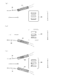
- FIG. 4 is a view showing the arrangement of magnetic members and the uneven distribution of disturbance magnetic fields in the first embodiment.
- FIG. 5 is a waveform diagram for explaining detection of a magnetic stripe.
- FIG. 6 is a side cross-sectional view of a card reader according to a modification of the first embodiment.
- FIG. 7 is a side sectional view of the card reader according to the second embodiment.
- FIG. 8 is a view showing the arrangement of magnetic members and the uneven distribution of disturbance magnetic fields in the second embodiment.
- FIG. 9 is a view showing another example of the arrangement of magnetic members in the second embodiment and the uneven distribution of the disturbing magnetic field.
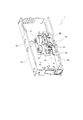
- FIG. 10 is a perspective view of the card reader as seen from the back side.
- FIG. 11 is a plan view of the card reader as seen from the back side.
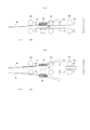
- FIG. 12 is a cross-sectional view taken along a line XX and a cross-sectional view taken along a line YY of FIG.
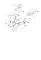
- FIG. 13 is an exploded view of the magnetic body and the holding member.
- FIG. 14 is an assembly view of the magnetic body and the holding member.
- FIG. 15 is a view showing the arrangement of magnetic members and the uneven distribution of disturbance magnetic fields in the third embodiment.
- FIG. 16 is a view showing another example of the arrangement of magnetic members in the third embodiment and the uneven distribution of the disturbing magnetic field.
- FIG. 17 is a view showing the arrangement of magnetic members and the uneven distribution of disturbance magnetic fields in the fourth embodiment.
- FIG. 18 is a view showing another example of the arrangement of magnetic members in the fourth embodiment and the uneven distribution of the disturbing magnetic field.
- FIG. 19 is a view showing the arrangement of magnetic members and the uneven distribution of disturbance magnetic fields in the fifth embodiment.
- FIG. 20 is a side sectional view of a conventional card reader.
- FIG. 2 F indicates the forward direction
- B indicates the backward direction
- L indicates the left direction
- R indicates the right direction
- U indicates the upward direction
- D indicates the downward direction (the same applies to the subsequent figures).
- a card reader 1 includes a control unit 2 comprising a CPU for controlling the operation of the entire apparatus, a magnetic information reading unit 3 for reading magnetic data recorded on a magnetic card, A connection unit between a card conveyance unit 4 for conveying a card, a card detection sensor 5 for detecting a magnetic card, a memory 6 for storing magnetic data read by the magnetic information reading unit 3, and a host device (for example, ATM)
- a host interface 7, a magnetic stripe detection unit 10 for detecting a magnetic stripe of a magnetic card, and a magnetic field generation unit 8 for generating an interference magnetic field for preventing reading of data recorded in the magnetic stripe are provided.
- the control unit 2 includes a magnetic field control unit 9 that controls the magnetic field generation unit 8 and a card transport control unit 12 that controls the card transport unit 4.
- the magnetic stripe detection unit 10 and the magnetic field generation unit 8 are installed in the card insertion slot unit 24.
- the magnetic stripe detection unit 10 includes a magnetic head 34 (FIG. 2) described later.
- the configuration of FIG. 1 is common to each embodiment described later.
- a card insertion slot unit 24 is provided on the front of the housing 100 of the card reader 1.
- the card insertion slot unit 24 is formed with an insertion slot 22 into which a magnetic card (hereinafter simply referred to as a "card") 21 is inserted.
- the card 21 has a magnetic stripe 21a as shown in FIG. FIG. 3 is a view of the card 21 viewed from the back.
- a card insertion detection sensor 23 for detecting the inserted card 21, a magnetic head 34 for detecting the magnetic stripe 21a of the card 21, and a magnetic field generator 8 for generating a disturbing magnetic field are provided. ing.
- the magnetic field generator 8 includes, for example, an iron core and a coil wound around it. As can be seen from FIG. 2B, the magnetic field generator 8 is provided on the side of the magnetic head 34 for detecting the magnetic stripe toward the insertion port 22.
- transport rollers 25-28 Inside the housing 100 of the card reader 1, transport rollers 25-28, card position detection sensors 30-33, and a magnetic head 29 are provided.
- the transport rollers 25 to 28 are respectively provided in a pair on both sides of the transport path P, and transport the card 21 by nipping the pair of rollers.
- the transport rollers 25 to 28 are connected to a motor (not shown) via a transport belt (not shown).
- One of the pair of transport rollers is a drive roller to which the rotational force of the motor is transmitted, and the other is a driven roller that rotates following the drive roller.
- the transport rollers 25 to 28 constitute a card transport unit 4 (FIG. 1) together with the above-described transport belt and motor.
- the card transport unit 4 is an example of the “transport unit” in the present invention.
- the card position detection sensors 30 to 33 are transmission type optical sensors, and each have a light emitting unit and a light receiving unit opposed to each other with the transport path P interposed therebetween.
- the arrangement interval of these sensors 30 to 33 is shorter than the length of the magnetic card 21 in the transport direction.
- the sensor 30 detects that the card 21 is pinched by the transport roller 25 closest to the insertion port 22.
- the sensor 33 detects that the inserted card 21 has reached a storage unit (not shown) that temporarily stores the card.
- the sensors 31, 32 detect the position of the card 21 being transported.
- These card position detection sensors 30 to 33, together with the card insertion detection sensor 23, constitute a card detection sensor 5 (FIG. 1).
- the magnetic head 29 is provided on the lower side of the conveyance path P between the conveyance roller 26 and the conveyance roller 27.
- the magnetic head 29 reads the data recorded on the magnetic stripe 21 a of the card 21 while the inserted card 21 is transported on the transport path P.
- the magnetic head 34 described above is a magnetic head for detecting the presence or absence of data recorded in the magnetic stripe
- the magnetic head 29 is a magnetic for reproducing the data recorded in the magnetic stripe itself. It is a head.
- a magnetic body 40 is provided on the lower side (direction D) of the magnetic head 29.
- the magnetic body 40 is made of a high magnetic permeability material such as ferrite or iron.
- the card reader 1 is disposed inside the panel 200 of the transaction processing apparatus.
- the card 21 inserted from the opening of the panel 200 in the A direction is guided to the insertion opening 22 of the card reader 1.
- the card reader 1 constitutes a magnetic recording medium reading device of the present invention.
- the magnetic field generation unit 8 Under the control of the magnetic field control unit 9 (FIG. 1), when the drive current flows in the magnetic field generation unit 8, the magnetic field generation unit 8 generates a disturbing magnetic field.
- the magnetic field generating unit 8 constantly generates the disturbing magnetic field by continuously supplying the drive current to the magnetic field generating unit 8.
- the disturbing magnetic field generated by the magnetic field generator 8 extends forward (F direction) and acts on the unauthorized reader 300. Therefore, the data read by the unauthorized reader 300 is different from the original data recorded in the card 21 under the influence of the disturbing magnetic field. Thereby, it is possible to prevent the data of the card 21 from being illegally acquired.
- the disturbing magnetic field generated by the magnetic field generating unit 8 also exists behind the magnetic field generating unit 8 (direction B).
- the disturbance magnetic field M is distributed so as to pass through the magnetic body 40 as shown in FIG. 4A. Therefore, the disturbing magnetic field M does not reach the magnetic head 29 for reading magnetic data, and the magnetic head 29 can read the data of the card 21 without being affected by the disturbing magnetic field M.
- the magnetic body 40 may be disposed to be inclined in the D direction with respect to the magnetic head 29 (with respect to the FB direction). As a result, since the disturbing magnetic field M is biased away from the magnetic head 29, the disturbing magnetic field M is more difficult to reach the magnetic head 29.
- the skimming is prevented by causing the disturbing magnetic field generated from the magnetic field generating unit 8 to act on the unauthorized reader 300 attached to the front surface of the panel 200. it can.
- the disturbing magnetic field generated by the magnetic field generating unit 8 is less likely to reach the magnetic head 29 in the card reader 1, so the data reading performance is improved. It is possible to avoid falling.
- the disturbing magnetic field generated by the magnetic field generator 8 also acts on the magnetic head 34 for detecting the magnetic stripe. For this reason, even when the unauthorized reader is connected to the magnetic head 34 via the lead wire, it is possible to prevent the data from being acquired illegally. Even if the disturbing magnetic field always acts on the magnetic head 34, the magnetic head 34 does not have to reproduce the magnetic data itself, so for example, utilizing the fact that the pattern of the detection signal is different before and after detection of the magnetic stripe 21a. Thus, the magnetic stripe 21a can be detected. This will be described with reference to FIG.
- FIG. 5A shows the waveform of the drive current flowing to the magnetic field generator 8.
- the magnetic field generator 8 generates a disturbing magnetic field according to the drive current.
- FIG. 5B is a waveform of a detection signal output from the magnetic head 34 when no disturbing magnetic field is present.
- FIG. 5C shows the waveform of the detection signal output from the magnetic head 34 when the disturbing magnetic field is present, and is a waveform obtained by combining FIG. 5A and FIG. 5B.
- the pattern of the detection signal is different before and after the time t at which the magnetic stripe is detected. Therefore, the magnetic stripe can be detected by changing the pattern (the same applies to the following embodiments).
- the magnetic body 36 may be disposed in front of the magnetic field generating unit 8 between the panel 200 and the card slot unit 24 (each embodiment described hereinafter) But the same).
- the magnetic body 36 is made of a material having high permeability such as ferrite or iron.
- the magnetic body 36 is attached to, for example, a support member (not shown) provided on the panel 200.
- a loop antenna may be disposed.
- the disturbing magnetic field generated by the magnetic field generation unit 8 is guided to the magnetic body 36 serving as a kind of waveguide and extends forward, so that the fraudulent reading device 300 exerts a strong disturbing magnetic field. be able to. Therefore, skimming by the unauthorized reader 300 can be prevented more effectively.
- FIG. 7 shows a card reader 1 according to the second embodiment.
- the magnetic body 40 is provided below the magnetic head 29.
- the magnetic body 40 is provided on the side of the magnetic head 29.
- FIG. 7A the magnetic body 40 is provided on the front side of the magnetic head 29, and in FIG. 7B, the magnetic body 40 is provided on the other side of the magnetic head 29.
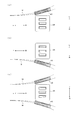
- FIG. 8 is a top view of the magnetic head 29.
- the magnetic body 40 is provided on the side of the magnetic head 29 in the L direction, and the disturbance magnetic field M is distributed in the L direction through the magnetic body 40.
- the magnetic body 40 is provided on the side of the magnetic head 29 in the R direction, and the disturbance magnetic field M is distributed in the R direction through the magnetic body 40.
- the magnetic bodies 40 are provided on each side of the magnetic head 29 in the L and R directions, and the disturbance magnetic field M passes through these magnetic bodies 40 and is unevenly distributed in the L and R directions. doing.
- the skimming is prevented by acting the disturbing magnetic field generated from the magnetic field generating unit 8 on the unauthorized reader 300 attached to the front surface of the panel 200. it can.
- the disturbing magnetic field generated in the magnetic field generation unit 8 becomes difficult to reach the magnetic head 29 in the card reader 1, so the data reading performance is improved. It is possible to avoid falling.
- the magnetic body 40 is disposed in parallel with the magnetic body 40 in FIG. 8, the magnetic body 40 may be disposed at an angle to the magnetic head 29 as shown in FIG. 9. As a result, the disturbance magnetic field M can be biased away from the magnetic head 29 so that the disturbance magnetic field M is more difficult to reach the magnetic head 29.
- FIG. 10 is a perspective view of the card reader 1 viewed from the back side
- FIG. 11 is a plan view of the card reader 1 viewed from the back side. In both figures, illustration is omitted about a part of parts.
- the cross-sectional view taken along the line XX in FIG. 11 is shown in FIG. 12 (a), and the cross-sectional view taken along the line YY in FIG. 11 is shown in FIG. 12 (b).
- a magnetic head 29 and a plurality of transport rollers 61 are provided inside the housing 100.
- the magnetic head 29 projects in the U direction (upper side) from the opening 60 formed in the housing 100 and faces the transport path P, as shown in FIG.
- the conveyance roller 61 also protrudes in the U direction (upper side) from the opening 62 (see FIGS. 10 and 11) formed in the housing 100 and faces the conveyance path P.
- the magnetic body 41 (first magnetic body) is located below the magnetic head 29 (direction D), and the magnetic body 42 (second magnetic body) is The magnetic head 29 is located on the side (L direction).
- These magnetic bodies 41 and 42 are held by a holding member 50 made of a resin molded product.
- the holding member 50 includes a holding portion 51 (first holding portion) holding the magnetic body 41, a holding portion 52 (second holding portion) holding the magnetic body 42, and a holding member A fixing piece 53 for fixing the card 50 to the card reader main body and a stopper piece 54 for restricting the movement of the holding member 50 are provided.
- the holding portion 51 and the holding portion 52 are integrally formed to form a predetermined angle.
- the holding portion 51 is formed with a pair of engaging portions 51 a and 51 b (first engaging portions) engaging with the magnetic body 41, and the holding portion 52 includes three engaging portions with the magnetic body 42. Engaging portions 52a, 52b, 52c (second engaging portions) are formed.
- the magnetic bodies 41 and 42 consist of a commercially available ferrite core for noise shielding attached to a flat cable. For this reason, the magnetic body 41 has a flat shape, and a through hole 41a through which a flat cable (not shown) is inserted is formed at the center. Similarly, the magnetic body 42 also has a flat shape, and a through hole 42a through which a flat cable is inserted is formed at the center.
- the magnetic body 41 is held as shown in FIG. 14 by the one open end of the through hole 41a engaging with the engaging portion 51a and the other open end of the through hole 41a engaging with the engaging portion 51b. It is held by the unit 51. As shown in FIG. 14, the magnetic body 42 has one open end of the through hole 42a engaged with the engaging portions 52a and 52b, and the other open end of the through hole 42a engaged with the engaging portion 52c. Is held by the holding unit 52.
- 14A is a view of the holding member 50 viewed obliquely from above
- FIG. 14B is a view of the holding member 50 viewed from the side.
- the magnetic body 41 is disposed to obliquely face the magnetic head 29, and the end portion of the magnetic body 41 on the side (the L direction side) away from the magnetic head 29.
- the magnetic body 42 is disposed in the vicinity of 41 b.
- the magnetic body 41 is obliquely disposed to prevent interference with the other members (not shown) in the installation space of the magnetic body 41.
- the disturbing magnetic field is distributed so as to pass through the magnetic body 41.
- the distance between the magnetic body 41 and the magnetic head 29 increases, so the effect of the magnetic body 41 inducing the disturbing magnetic field is not sufficiently exerted, and the magnetic head 29 is affected by the disturbing magnetic field.
- the disturbing magnetic field is induced to the magnetic body 42 and unevenly distributed, so the disturbing magnetic field does not reach the magnetic head 29.
- each magnetic body 41, 42 can be easily mounted to the holding member 50 by engagement. Furthermore, since the holding portions 51 and 52 are integrally formed on the holding member 50 so as to form a predetermined angle, the magnetic members 41 and 42 can be obtained simply by holding the magnetic members 41 and 42 in the holding portions 51 and 52, respectively. 42 can be positioned at a predetermined angle, which can improve the efficiency of assembly work.
- the holding member 50 when the holding member 50 is fixed to the card reader main body by the fixing piece 53, the movement of the holding member 50 is restricted by bringing the stopper piece 54 into contact with a part of the main body. It can be fixed in a stable state to the reader body.
- ferrite cores for noise shielding to be attached to flat cables are used as the magnetic bodies 41 and 42, there is no need to design and manufacture a magnetic body as a dedicated part, and a commercially available general-purpose part readily available. As a result, the manufacturing cost can be kept low.
- FIG. 15 shows the arrangement of the magnetic body 40 and the uneven distribution of the disturbing magnetic field in the third embodiment, and is a view of the magnetic head 29 as viewed from above.
- the magnetic body 40 is provided in front of the magnetic head 29 (direction F).
- the magnetic body 40 is disposed at the diagonally forward position on the F direction side and the L direction side as viewed from the magnetic head 29.
- the magnetic body 40 is provided to be inclined in the L direction with respect to the FB direction.
- the disturbing magnetic field M is guided to the magnetic body 40 and unevenly distributed in the direction away from the magnetic head 29 (L direction), and does not reach the magnetic head 29.
- the magnetic body 40 is disposed at the diagonally forward position on the F direction side and the R direction side as viewed from the magnetic head 29.
- the magnetic body 40 is provided to be inclined to the R direction side with respect to the FB direction.
- the disturbing magnetic field M is guided to the magnetic body 40 and unevenly distributed in the direction (R direction) away from the magnetic head 29 and does not reach the magnetic head 29.
- the magnetic body 40 is disposed at the diagonally forward position on both the F direction side and both the L direction side and the R direction side as viewed from the magnetic head 29.
- the magnetic body 40 is provided to be inclined in the L direction and in the R direction with respect to the FB direction.
- the disturbing magnetic field M is guided by the two magnetic members 40 and unevenly distributed in the directions (L direction and R direction) away from the magnetic head 29 and does not reach the magnetic head 29.
- FIG. 16 shows another example of the arrangement of the magnetic body 40.
- FIG. 16A is a view of the magnetic head 29 as viewed from the side.
- FIG. 16B is a top view of the magnetic head 29.
- the magnetic body 40 is disposed at the diagonally forward position on the F direction side and the D direction side as viewed from the magnetic head 29.
- the magnetic body 40 is provided to be inclined in the D direction with respect to the FB direction. As a result, the disturbing magnetic field M is guided to the magnetic body 40 and unevenly distributed in the direction (D direction) away from the magnetic head 29 and does not reach the magnetic head 29.
- the magnetic body 40 is disposed at the diagonally forward position on the F direction side and in the U direction side as viewed from the magnetic head 29 with respect to the FB direction You may incline and provide in the U direction side. In this case, the disturbing magnetic field is localized in the U direction and does not reach the magnetic head 29. Also, the magnetic body 40 may be disposed at the diagonally forward position on both the F direction side and the D direction side and the U direction side as viewed from the magnetic head 29.
- skimming is performed by causing the disturbing magnetic field generated from the magnetic field generation unit 8 to act on the unauthorized reader 300 (FIG. 2) attached to the front surface of the panel 200. It can be prevented.
- the magnetic body 40 at the diagonally forward position of the magnetic head 29, the disturbing magnetic field generated by the magnetic field generation unit 8 is difficult to reach the magnetic head 29 in the card reader 1, so the data reading performance Can be avoided.
- FIG. 17 shows the arrangement of the magnetic body 40 and the uneven distribution of the disturbing magnetic field in the fourth embodiment, and is a view of the magnetic head 29 as viewed from above.
- the magnetic body 40 is provided at the rear (direction B) of the magnetic head 29.
- the magnetic body 40 is disposed at the diagonally back position on the B direction side and the L direction side as viewed from the magnetic head 29.
- the magnetic body 40 is provided to be inclined in the L direction with respect to the FB direction.
- the disturbing magnetic field M is guided to the magnetic body 40 and unevenly distributed in the direction away from the magnetic head 29 (L direction), and does not reach the magnetic head 29.
- the magnetic body 40 is disposed at the diagonally back position on the B direction side and the R direction side as viewed from the magnetic head 29.
- the magnetic body 40 is provided to be inclined to the R direction side with respect to the FB direction.
- the disturbing magnetic field M is guided to the magnetic body 40 and unevenly distributed in the direction (R direction) away from the magnetic head 29 and does not reach the magnetic head 29.
- the magnetic body 40 is disposed at a diagonally back position on both the B direction side and both the L direction side and the R direction side as viewed from the magnetic head 29.
- the magnetic body 40 is provided to be inclined in the L direction and in the R direction with respect to the FB direction.
- the disturbing magnetic field M is guided by the two magnetic members 40 and unevenly distributed in the directions (L direction and R direction) away from the magnetic head 29 and does not reach the magnetic head 29.
- FIG. 18 shows another example of the arrangement of the magnetic body 40.
- FIG. 18A is a view of the magnetic head 29 as viewed from the side.
- FIG. 18B is a top view of the magnetic head 29.
- the magnetic body 40 is disposed at the diagonally back position on the B direction side and the D direction side as viewed from the magnetic head 29.
- the magnetic body 40 is provided to be inclined in the D direction with respect to the FB direction. As a result, the disturbing magnetic field M is guided to the magnetic body 40 and unevenly distributed in the direction (D direction) away from the magnetic head 29 and does not reach the magnetic head 29.
- the magnetic body 40 is disposed at the diagonally back position on the B direction side and the U direction side as viewed from the magnetic head 29, and in the FB direction You may incline and provide in the U direction side. In this case, the disturbing magnetic field is localized in the U direction and does not reach the magnetic head 29.
- the magnetic body 40 may be disposed at the diagonally backward position on both the B direction side and both the D direction side and the U direction side when viewed from the magnetic head 29.
- skimming is performed by causing the disturbing magnetic field generated from the magnetic field generation unit 8 to act on the unauthorized reader 300 (FIG. 2) attached to the front surface of the panel 200. It can be prevented.
- the magnetic body 40 at the diagonally back position of the magnetic head 29, the disturbing magnetic field generated by the magnetic field generation unit 8 is difficult to reach the magnetic head 29 in the card reader 1, so the data reading performance Can be avoided.
- the overall configuration of the card reader according to the fifth embodiment is the same as that shown in FIG. 2 except for the arrangement of the magnetic members 40, so the description will be omitted.
- FIG. 19 shows the arrangement of the magnetic body 40 and the uneven distribution of the disturbing magnetic field in the fifth embodiment, and is a view of the magnetic head 29 as viewed from the side.
- the magnetic body 40 is provided on the upper side (U direction) of the magnetic head 29.
- the magnetic body 40 is disposed at a position facing the magnetic head 29 with the transport path P interposed therebetween.
- the magnetic body 40 may be provided to be inclined in the U direction with respect to the FB direction.
- the disturbing magnetic field M is more difficult to reach the magnetic head 29.
- the magnetic body 40 may be provided on both the upper side (U direction) and the lower side (D direction) of the magnetic head 29. Also in this case, the magnetic body 40 may be provided to be inclined to the U direction side and the D direction side with respect to the FB direction.
- skimming is performed by causing the disturbing magnetic field generated from the magnetic field generation unit 8 to act on the unauthorized reader 300 (FIG. 2) attached to the front surface of the panel 200. It can be prevented.
- the disturbing magnetic field generated in the magnetic field generating unit 8 becomes difficult to reach the magnetic head 29 in the card reader 1, and the data reading performance decreases. You can avoid doing so.
- the magnetic body 40 may be disposed at at least one or more of the lower side, the upper side, the side, the front, and the rear of the magnetic head 29. As a result, the magnetic body 40 can be disposed at an optimum position in accordance with the conditions such as parts and spaces existing around the magnetic head 29.
- the magnetic bodies 41 and 42 are configured as separate parts, but a single L-shaped or V-shaped magnetic body obtained by integrating these may be used.
- the magnetic field generation part 8 was comprised from the iron core and the coil wound by this, the magnetic field generation part 8 in this invention is not limited only to this.
- the magnetic field generator 8 may be configured by a loop antenna.
- the disturbance magnetic field is always generated from the magnetic field generation unit 8
- the skimming is also performed when the card 21 is returned. It can be prevented. It is not essential for the present invention to always generate the disturbing magnetic field, and the disturbing magnetic field may have a pause period.
- the skimming for the unauthorized reader 300 attached to the front of the panel 200 and the skimming for the magnetic stripe 34 for magnetic stripe detection have been described.
- a countermeasure against skimming of the magnetic head 29 for reading the magnetic data for example, a countermeasure such as encryption of data read by the magnetic head 29 is taken.
- a magnetic card having a magnetic stripe on the back surface is taken as an example of the magnetic recording medium.
- the present invention can also be applied to a magnetic recording medium reader that handles magnetic cards having magnetic stripes on the front or both sides.
- a magnetic card is taken as an example of the magnetic recording medium.
- the present invention is applicable not only to the magnetic card but also to an apparatus for reading a magnetic recording medium such as a passbook having a magnetic stripe.
- the present invention can be generally applied to an apparatus for reading a magnetic recording medium, such as a card reader or a passbook reader mounted on an automatic transaction processing apparatus such as an ATM, or a card reader mounted on a card authentication terminal.
- a magnetic recording medium such as a card reader or a passbook reader mounted on an automatic transaction processing apparatus such as an ATM, or a card reader mounted on a card authentication terminal.
Landscapes
- Business, Economics & Management (AREA)
- Accounting & Taxation (AREA)
- Finance (AREA)
- Physics & Mathematics (AREA)
- General Physics & Mathematics (AREA)
- Recording Or Reproducing By Magnetic Means (AREA)
Abstract
カードリーダ(1)は、磁気カード(21)が挿入される挿入口(22)と、挿入口(22)から挿入された磁気カード(21)を搬送する搬送手段(25~28)と、搬送される磁気カード(21)からデータを読み取る磁気ヘッド(29)と、挿入口(22)付近に設けられる磁界発生部(8)とを備える。磁界発生部(8)から発生する妨害磁界が、パネル(200)の前面に取り付けられた不正読取装置(300)に作用することで、磁気カード(21)のデータの不正取得を防止する。また、磁気ヘッド(29)の下側に磁性体(40)を配置し、磁界発生部(8)から後方に延びる磁界を偏在させて、磁気ヘッド(29)に妨害磁界が及ばないようにする。
Description
本発明は、磁気記録媒体に記録されたデータを読み取る装置に関し、特に、データの不正取得を防止する機能を備えた磁気記録媒体読取装置に関する。
ATM(Automated Teller Machine:現金自動預け払機)やCD(Cash Dispenser:現金自動支払機)などの取引処理装置には、磁気カードを読み取るカードリーダが搭載されている。このような取引処理装置において、最近では、磁気カードがカードリーダに挿入される際に、カードの磁気ストライプに記録されたデータを不正に取得するスキミングと呼ばれる犯罪が発生している。
典型的なスキミングの例として、磁気ヘッドを備えた不正読取装置を、ATMやCDに備わるカードリーダのカード挿入口の付近に設置し、この不正読取装置の磁気ヘッドにより、カードリーダに挿入される磁気カードのデータを不正に取得する方法がある。
上記のようなスキミングに対しては、これまでにも種々の対策が提案されている。例えば、後掲の特許文献1には、カード挿入口の近傍に妨害磁界発生器を設けたカードリーダが記載されている。このカードリーダにおいては、妨害磁界発生器により、カード挿入口の外側領域に妨害磁界が発生する。このため、カード挿入口の外側に不正読取装置が取り付けられたとしても、当該装置で読み取ったデータは、妨害磁界の影響を受けて、カードに記録された元のデータとは異なるデータとなる。これにより、カードのデータが不正に取得されるのを防止することができる。
また、後掲の特許文献2には、カード挿入口の周囲に、妨害磁界を発生させるためのループアンテナを配設したカードリーダが記載されている。ループアンテナのアンテナ面は、カード挿入口の前面と平行になっている。このカードリーダにおいても、カード挿入口の外側領域に妨害磁界が発生するので、カード挿入口の外側に不正読取装置が取り付けられたとしても、カードのデータが不正に取得されるのを防止することができる。
図20は、妨害磁界発生器を備えたカードリーダの一例を示している。カードリーダ1の筐体100の前面に、カード挿入口ユニット24が設けられている。カード挿入口ユニット24には、磁気カード21が挿入される挿入口22が形成されている。挿入口22の付近には、挿入されたカード21を検出するカード挿入検出センサ23と、カード21の磁気ストライプを検出する磁気ヘッド34と、妨害磁界を発生する妨害磁界発生器35とが設けられている。
筐体100の内部には、カード21を搬送する搬送ローラ25~28、カード21の位置を検出するカード位置検出センサ30~33、磁気カード21のデータを読み取る磁気ヘッド29などが設けられている。カードリーダ1は、取引処理装置のパネル200の内側に配設されている。妨害磁界発生器35の発生する妨害磁界は、パネル200の前面に取り付けられる不正読取装置300に作用し、A方向に挿入される磁気カード21からデータが不正取得されるのを阻止する。
図20に示したカードリーダ1において、不正読取装置300におけるスキミングを確実に防止するために、妨害磁界の強度を強くすればするほど、妨害磁界発生器35の後方側に生じる磁界の強度も強くなるので、筐体100内の磁気ヘッド29へ妨害磁界が及んで、データの読取性能が低下するという問題がある。
そこで、本発明の目的は、不正読取装置に対して強い妨害磁界を作用させつつも、妨害磁界が磁気ヘッドへ及ばないようにすることで、データの読取性能が低下しないようにした磁気記録媒体読取装置を提供することにある。
本発明に係る磁気記録媒体読取装置は、磁気記録媒体が挿入される挿入口と、この挿入口から挿入された磁気記録媒体を搬送する搬送手段と、この搬送手段により搬送される磁気記録媒体からデータを読み取る磁気ヘッドと、挿入口付近に設けられ、当該挿入口の前方に取り付けられる不正読取装置によって磁気記録媒体のデータが読み取られるのを妨害する妨害磁界を発生する磁界発生部とを備えている。また、磁界発生部から発生する妨害磁界を偏在させて、磁気ヘッドに及ばないようにするための磁性体が、磁気ヘッドの下側に配置されている。
このようにすると、磁界発生部から後方に発生する妨害磁界が、磁気ヘッドの下側に配置された磁性体を通るように偏在するので、妨害磁界が磁気ヘッドに及ばなくなる。このため、磁気ヘッドでは、妨害磁界に影響されずに磁気記録媒体のデータを読み取ることができ、データの読取性能が低下することが回避される。
本発明では、磁性体を、磁気ヘッドの下側および側方に配置してもよい。
これによると、磁界発生部の妨害磁界が磁気ヘッドの下側だけでなく側方へも偏在するので、妨害磁界が磁気ヘッドに一層及びにくくなる。
この場合、磁性体は、磁気ヘッドの下側に配置される第1の磁性体と、磁気ヘッドの側方に配置される第2の磁性体とからなり、第1の磁性体は、磁気ヘッドと斜めに対向するように配置されており、第1の磁性体の磁気ヘッドから離れる側の端部の近傍に、第2の磁性体が配置されていてもよい。
磁性体の設置スペースの都合で、第1の磁性体を磁気ヘッドと斜めに対向するように配置せざるを得ないことがある。この場合、第1の磁性体の磁気ヘッドから離れる側の端部においては、第1の磁性体と磁気ヘッドとの距離が開くため、磁気ヘッドが妨害磁界の影響を受ける可能性がある。しかるに、第1の磁性体の上記端部の近傍に、第2の磁性体を配置すると、妨害磁界が第2の磁性体に誘導されて偏在するので、磁気ヘッドに妨害磁界が及びにくくなる。
本発明では、第1および第2の磁性体を保持する保持部材を設け、この保持部材は、第1の磁性体を保持する第1の保持部と、第2の磁性体を保持する第2の保持部とを有し、第1の保持部と第2の保持部とが、所定の角度をなすように一体形成されていてもよい。
これによると、第1の磁性体を保持部材の第1の保持部に保持させ、第2の磁性体を保持部材の第2の保持部に保持させるだけで、第1の磁性体と第2の磁性体とを所定の角度で位置決めすることができ、組立作業の効率化を図ることができる。
本発明では、保持部材の第1の保持部は、第1の磁性体と係合する第1の係合部を有し、第2の保持部は、第2の磁性体と係合する第2の係合部を有していてもよい。
これによると、第1の磁性体を保持部材の第1の係合部に係合させ、第2の磁性体を保持部材の第2の係合部に係合させることにより、各磁性体を保持部材に簡単に装着することができる。
本発明では、保持部材は、装置本体に固定するための固定片と、当該保持部材の動きを規制するためのストッパ片とを備えていてもよい。
これによると、保持部材を固定片により装置本体に固定した場合に、ストッパ片により保持部材の動きが規制されるので、保持部材を装置本体に安定した状態で固定することができる。
本発明では、第1および第2の磁性体は、フラットケーブルに装着されるノイズ遮蔽用のフェライトコアであってもよい。
これによると、専用部品としての磁性体を設計・製造する必要がなく、容易に入手できる市販の汎用部品を利用できるので、結果的に製造コストを低く抑えることができる。
本発明では、磁性体を、磁気ヘッドの上側、側方、前方、および後方の少なくとも1つ以上の場所に配置してもよい。
これによると、磁気ヘッド周辺に存在する部品やスペースなどの状況に応じて、最適の場所に磁性体を配置することができる。
本発明では、磁界発生部から発生する妨害磁界が磁気ヘッドから離れる方向へ偏在するように、磁性体を磁気ヘッドに対して傾けて配置してもよい。
これによると、磁界発生部の妨害磁界が磁気ヘッドから離れる方向へ偏在するので、妨害磁界が磁気ヘッドに一層及びにくくなる。
本発明によれば、不正読取装置に対して強い妨害磁界を作用させても、妨害磁界が磁気ヘッドへ及ばないので、データの読取性能が低下しない磁気記録媒体読取装置を提供することができる。
以下、本発明の実施形態について、図面を参照しながら説明する。各図において、同一符号は、同一部分または対応部分を表している。
(第1実施形態)
まず、図1および図2を参照して、第1実施形態によるカードリーダの構成について説明する。なお、図2中のFは前方向、Bは後方向、Lは左方向、Rは右方向、Uは上方向、Dは下方向をそれぞれ表している(以降の図においても同様)。
まず、図1および図2を参照して、第1実施形態によるカードリーダの構成について説明する。なお、図2中のFは前方向、Bは後方向、Lは左方向、Rは右方向、Uは上方向、Dは下方向をそれぞれ表している(以降の図においても同様)。
図1に示すように、本実施形態によるカードリーダ1は、装置全体の動作を制御するCPUからなる制御部2と、磁気カードに記録されている磁気データを読み取る磁気情報読取部3と、磁気カードを搬送するカード搬送部4と、磁気カードを検出するカード検出センサ5と、磁気情報読取部3で読み取った磁気データを記憶するメモリ6と、上位装置(例えばATM)との接続部であるホストインターフェース7と、磁気カードの磁気ストライプを検出する磁気ストライプ検出部10と、磁気ストライプに記録されたデータの読み取りを妨げるための妨害磁界を発生する磁界発生部8とを備えている。
制御部2は、磁界発生部8を制御する磁界制御部9と、カード搬送部4を制御するカード搬送制御部12とを含む。磁気ストライプ検出部10および磁界発生部8は、カード挿入口ユニット24内に設置されている。磁気ストライプ検出部10は、後述する磁気ヘッド34(図2)を含む。なお、図1の構成は、後述する各実施形態に共通である。
図2(a)に示すように、カードリーダ1の筐体100の前面には、カード挿入口ユニット24が設けられている。カード挿入口ユニット24には、磁気カード(以下、単に「カード」という。)21が挿入される挿入口22が形成されている。カード21は、図3に示すように、磁気ストライプ21aを有している。図3は、カード21を裏面から見た図である。挿入口22の付近には、挿入されたカード21を検出するカード挿入検出センサ23と、カード21の磁気ストライプ21aを検出する磁気ヘッド34と、妨害磁界を発生する磁界発生部8とが設けられている。
磁界発生部8は、例えば、鉄心と、これに巻回されたコイルとから構成される。図2(b)からわかるように、磁界発生部8は、挿入口22に向って、磁気ストライプ検出用の磁気ヘッド34側に設けられている。
カードリーダ1の筐体100の内部には、搬送ローラ25~28、カード位置検出センサ30~33、磁気ヘッド29が設けられている。搬送ローラ25~28は、それぞれ搬送路Pを挟んで1対設けられており、1対のローラでカード21を挟持して搬送する。これらの搬送ローラ25~28は、搬送ベルト(図示省略)を介して、モータ(図示省略)に連結されている。1対の搬送ローラのうち、一方はモータの回転力が伝達される駆動ローラであり、他方はこの駆動ローラに従動して回転する従動ローラである。搬送ローラ25~28は、上記の搬送ベルトおよびモータとともに、カード搬送部4(図1)を構成する。カード搬送部4は、本発明における「搬送手段」の一例である。
カード位置検出センサ30~33は、透過型の光センサであり、それぞれ、搬送路Pを挟んで対向する発光部と受光部を有している。これらのセンサ30~33の配置間隔は、磁気カード21の搬送方向の長さよりも短くなっている。センサ30は、挿入口22に最も近い搬送ローラ25にカード21が挟持されたことを検出する。センサ33は、挿入されたカード21が、カードを一時的に貯留する貯留部(図示省略)に達したことを検出する。センサ31、32は、搬送中のカード21の位置を検出する。これらのカード位置検出センサ30~33は、前記のカード挿入検出センサ23とともに、カード検出センサ5(図1)を構成する。
磁気ヘッド29は、搬送ローラ26と搬送ローラ27との間で、搬送路Pの下側に設けられている。この磁気ヘッド29は、挿入されたカード21が搬送路Pを搬送される過程で、カード21の磁気ストライプ21aに記録されているデータを読み取る。前述の磁気ヘッド34が、磁気ストライプに記録されているデータの有無を検出するための磁気ヘッドであるのに対し、磁気ヘッド29は、磁気ストライプに記録されているデータそのものを再生するための磁気ヘッドである。磁気ヘッド29の下側(D方向)には、磁性体40が設けられている。この磁性体40は、フェライトや鉄のような透磁率の高い材料からなる。
カードリーダ1は、取引処理装置のパネル200の内側に配設されている。パネル200の開口からA方向に挿入されたカード21は、カードリーダ1の挿入口22へ導かれる。カードリーダ1は、本発明の磁気記録媒体読取装置を構成している。
次に、図2(a)のように、パネル200の前面に磁気ヘッドを含む不正読取装置300が取り付けられた場合のスキミング対策について説明する。
磁界制御部9(図1)の制御に基づき、磁界発生部8に駆動電流が流れると、磁界発生部8は、妨害磁界を発生させる。本実施形態では、磁界発生部8に継続して駆動電流を流すことで、磁界発生部8は常時、妨害磁界を発生している。磁界発生部8で発生した妨害磁界は、前方(F方向)へ延び、不正読取装置300に作用する。このため、不正読取装置300で読み取ったデータは、妨害磁界の影響を受けて、カード21に記録された元のデータとは異なるデータとなる。これにより、カード21のデータが不正に取得されるのを防止することができる。
一方、磁界発生部8で発生した妨害磁界は、磁界発生部8の後方(B方向)にも存在する。しかしながら、磁気ヘッド29の下側には磁性体40が配置されているので、図4(a)に示すように、妨害磁界Mは磁性体40を通るように偏在する。このため、妨害磁界Mが、磁気データ読取用の磁気ヘッド29に及ぶことがなく、磁気ヘッド29は、妨害磁界Mに影響されずにカード21のデータを読み取ることができる。
磁性体40は、図4(b)に示すように、磁気ヘッド29に対して(F-B方向に対して)、D方向側に傾けて配置してもよい。これにより、妨害磁界Mが磁気ヘッド29からより離れる方向へ偏在するので、妨害磁界Mが磁気ヘッド29に一層及びにくくなる。
このように、第1実施形態によれば、パネル200の前面に取り付けられた不正読取装置300に対しては、磁界発生部8から発生する妨害磁界を作用させることで、スキミングを防止することができる。また一方で、磁気ヘッド29の下側に磁性体40を配置したことにより、磁界発生部8で発生した妨害磁界が、カードリーダ1内の磁気ヘッド29に及びにくくなるので、データの読取性能が低下するのを回避することができる。
また、磁界発生部8で発生した妨害磁界は、磁気ストライプ検出用の磁気ヘッド34にも作用する。このため、磁気ヘッド34にリード線を介して不正読取装置が接続された場合でも、データが不正に取得されるのを防止することができる。なお、妨害磁界が常時磁気ヘッド34に作用しても、磁気ヘッド34は磁気データそのものを再生する必要はないので、例えば、磁気ストライプ21aの検出の前後で検出信号のパターンが異なることを利用して、磁気ストライプ21aを検出することができる。これを図5で説明する。
図5(a)は、磁界発生部8に流れる駆動電流の波形である。磁界発生部8からは、この駆動電流に応じた妨害磁界が発生する。図5(b)は、妨害磁界が存在しない場合に、磁気ヘッド34から出力される検出信号の波形である。図5(c)は、妨害磁界が存在する場合に、磁気ヘッド34から出力される検出信号の波形であり、図5(a)と図5(b)とを合成した波形となる。図5(c)からわかるように、磁気ストライプが検出された時刻tの前と後とでは、検出信号のパターンが異なる。したがって、このパターンの変化を以って、磁気ストライプの検出が可能となる(以降の各実施形態でも同様)。
上述したカードリーダ1において、図6に示すように、磁界発生部8の前方で、パネル200とカード挿入口ユニット24との間に、磁性体36を配置してもよい(以降の各実施形態でも同様)。この磁性体36は、磁性体40と同様、フェライトや鉄のような透磁率の高い材料からなる。磁性体36は、例えば、パネル200に設けられた支持部材(図示省略)に取り付けられている。なお、磁性体36に代えて、ループアンテナを配置してもよい。
このような磁性体36を設けると、磁界発生部8で発生した妨害磁界が、一種の導波路となる磁性体36に導かれて前方へ延びるので、不正読取装置300に強い妨害磁界を作用させることができる。このため、不正読取装置300によるスキミングを、より効果的に防止することができる。
(第2実施形態)
次に、本発明の第2実施形態について説明する。
次に、本発明の第2実施形態について説明する。
図7は、第2実施形態によるカードリーダ1を示している。前記の第1実施形態(図2)では、磁気ヘッド29の下側に、磁性体40が設けられていた。これに対して、第2実施形態では、磁気ヘッド29の側方に、磁性体40が設けられている。図7(a)では、磁性体40は磁気ヘッド29の手前側に設けられており、図7(b)では、磁性体40は磁気ヘッド29の向こう側に設けられている。
第2実施形態における妨害磁界の分布は、図8のようになる。図8は、磁気ヘッド29を上から見た図である。図8(a)では、磁性体40が磁気ヘッド29のL方向の側方に設けられており、妨害磁界Mは、この磁性体40を通ってL方向に偏在している。図8(b)では、磁性体40が磁気ヘッド29のR方向の側方に設けられており、妨害磁界Mは、この磁性体40を通ってR方向に偏在している。図8(c)では、磁性体40が磁気ヘッド29のL方向とR方向の各側方に設けられており、妨害磁界Mは、これらの磁性体40を通ってL方向とR方向に偏在している。
このように、第2実施形態によれば、パネル200の前面に取り付けられた不正読取装置300に対しては、磁界発生部8から発生する妨害磁界を作用させることで、スキミングを防止することができる。また一方で、磁気ヘッド29の側方に磁性体40を配置したことにより、磁界発生部8で発生した妨害磁界が、カードリーダ1内の磁気ヘッド29に及びにくくなるので、データの読取性能が低下するのを回避することができる。
図8では、磁性体40を磁性体40と平行に配置しているが、図9に示すように、磁性体40を磁気ヘッド29に対して傾けて配置してもよい。これにより、妨害磁界Mを磁気ヘッド29からより離れる方向へ偏在させることができるので、妨害磁界Mが磁気ヘッド29に一層及びにくくなる。
次に、上述した第1実施形態と第2実施形態とを併用したカードリーダ1の実施例を、図10~図14を参照しながら説明する。
図10は、カードリーダ1を裏側からみた斜視図、図11は、カードリーダ1を裏側からみた平面図である。両図とも、部品の一部について図示を省略してある。図11のX-X断面図が図12(a)に、図11のY-Y断面図が図12(b)に、それぞれ示されている。
図10~図12において、筐体100の内部には、磁気ヘッド29と、複数の搬送ローラ61が設けられている。磁気ヘッド29は、図12に示すように、筐体100に形成された開口60からU方向(上側)に突出して、搬送路Pに臨んでいる。搬送ローラ61も、筐体100に形成された開口62(図10、図11参照)からU方向(上側)に突出して、搬送路Pに臨んでいる。
磁気ヘッド29の近傍には、妨害磁界を偏在させるための2個の磁性体41,42が配置されている。図12(b)に示すように、磁性体41(第1の磁性体)は、磁気ヘッド29の下側(D方向)に位置しており、磁性体42(第2の磁性体)は、磁気ヘッド29の側方(L方向)に位置している。これらの磁性体41,42は、樹脂成型品からなる保持部材50に保持されている。
図13に示すように、保持部材50は、磁性体41を保持する保持部51(第1の保持部)と、磁性体42を保持する保持部52(第2の保持部)と、保持部材50をカードリーダ本体に固定するための固定片53と、保持部材50の動きを規制するためのストッパ片54とを備えている。保持部51と保持部52とは、所定の角度をなすように一体形成されている。保持部51には、磁性体41と係合する一対の係合部51a,51b(第1の係合部)が形成されており、保持部52には、磁性体42と係合する3つの係合部52a,52b,52c(第2の係合部)が形成されている。
磁性体41,42は、フラットケーブルに装着されるノイズ遮蔽用の市販のフェライトコアからなる。このため、磁性体41は、扁平な形状をしていて、中心にフラットケーブル(図示省略)が挿通される貫通孔41aが形成されている。同様に、磁性体42も、扁平な形状をしていて、中心にフラットケーブルが挿通される貫通孔42aが形成されている。
磁性体41は、貫通孔41aの一方の開口端が係合部51aと係合し、貫通孔41aの他方の開口端が係合部51bと係合することにより、図14に示すように保持部51に保持される。磁性体42は、貫通孔42aの一方の開口端が係合部52a,52bと係合し、貫通孔42aの他方の開口端が係合部52cと係合することにより、図14に示すように保持部52に保持される。なお、図14の(a)は保持部材50を斜め上方から見た図であり、(b)は保持部材50を横から見た図である。
ところで、図12(b)に示すように、磁性体41は、磁気ヘッド29と斜めに対向するように配置されており、磁性体41の磁気ヘッド29から離れる側(L方向側)の端部41bの近傍に、磁性体42が配置されている。磁性体41を斜めに配置するのは、磁性体41の設置スペースに他の部材(図示省略)が存在することから、当該部材との干渉を避けるためである。
この場合、磁性体41のR方向側の端部41cにおいては、磁性体41と磁気ヘッド29との距離が短いので、妨害磁界は磁性体41を通るように偏在するが、磁性体41のL方向側の端部41bにおいては、磁性体41と磁気ヘッド29との距離が開くため、磁性体41が妨害磁界を誘導する効果が十分に発揮されず、磁気ヘッド29が妨害磁界の影響を受ける可能性がある。しかるに、磁性体41のL方向側の端部41bの近傍に磁性体42を配置したことにより、妨害磁界が磁性体42に誘導されて偏在するので、磁気ヘッド29に妨害磁界が及ばなくなる。
以上述べた図10~図14の実施例によれば、妨害磁界が磁気ヘッド29の下側だけでなく側方へも偏在するので、妨害磁界が磁気ヘッド29に一層及びにくくなる。また、各磁性体41,42を、係合によって保持部材50に簡単に装着することができる。さらに、保持部材50には、保持部51,52が所定の角度をなすように一体形成されているので、磁性体41,42をそれぞれ保持部51,52に保持させるだけで、磁性体41,42を所定の角度で位置決めすることができ、組立作業の効率化を図ることができる。
また、保持部材50を固定片53によりカードリーダ本体に固定した場合に、ストッパ片54を本体の一部に当接させることにより、保持部材50の動きが規制されるので、保持部材50をカードリーダ本体に安定した状態で固定することができる。
さらに、磁性体41,42として、フラットケーブルに装着されるノイズ遮蔽用のフェライトコアを用いているため、専用部品としての磁性体を設計・製造する必要がなく、容易に入手できる市販の汎用部品を利用できるので、結果的に製造コストを低く抑えることができる。
(第3実施形態)
次に、本発明の第3実施形態について説明する。第3実施形態のカードリーダの全体的な構成については、磁性体40の配置を除いて、図2と同じであるので、説明を省略する。
次に、本発明の第3実施形態について説明する。第3実施形態のカードリーダの全体的な構成については、磁性体40の配置を除いて、図2と同じであるので、説明を省略する。
図15は、第3実施形態における磁性体40の配置と妨害磁界の偏在を示しており、磁気ヘッド29を上から見た図である。図15においては、磁性体40が、磁気ヘッド29の前方(F方向)に設けられている。
詳しくは、図15(a)では、磁性体40は、磁気ヘッド29から見て、F方向側でかつL方向側の斜め前方位置に配置されている。そして、磁性体40は、F-B方向に対して、L方向側に傾いて設けられている。これにより、妨害磁界Mは、磁性体40に導かれて磁気ヘッド29から離れる方向(L方向)へ偏在し、磁気ヘッド29に及ばなくなる。
図15(b)では、磁性体40は、磁気ヘッド29から見て、F方向側でかつR方向側の斜め前方位置に配置されている。そして、磁性体40は、F-B方向に対して、R方向側に傾いて設けられている。これにより、妨害磁界Mは、磁性体40に導かれて磁気ヘッド29から離れる方向(R方向)へ偏在し、磁気ヘッド29に及ばなくなる。
図15(c)では、磁性体40は、磁気ヘッド29から見て、F方向側でかつL方向側とR方向側の両方の斜め前方位置に配置されている。そして、磁性体40は、F-B方向に対して、L方向側とR方向側に傾いて設けられている。これにより、妨害磁界Mは、2つの磁性体40に導かれて磁気ヘッド29から離れる方向(L方向およびR方向)へ偏在し、磁気ヘッド29に及ばなくなる。
図16は、磁性体40の配置の他の例を示している。図16(a)は、磁気ヘッド29を横から見た図である。図16(b)は、磁気ヘッド29を上から見た図である。磁性体40は、磁気ヘッド29から見て、F方向側でかつD方向側の斜め前方位置に配置されている。そして、磁性体40は、F-B方向に対して、D方向側に傾いて設けられている。これにより、妨害磁界Mは、磁性体40に導かれて磁気ヘッド29から離れる方向(D方向)へ偏在し、磁気ヘッド29に及ばなくなる。
なお、図16(a)に破線で示すように、磁性体40を、磁気ヘッド29から見て、F方向側でかつU方向側の斜め前方位置に配置し、F-B方向に対して、U方向側に傾けて設けてもよい。この場合は、妨害磁界はU方向へ偏在し、磁気ヘッド29に及ばなくなる。また、磁性体40を、磁気ヘッド29から見て、F方向側でかつD方向側とU方向側の両方の斜め前方位置に配置してもよい。
このように、第3実施形態によれば、パネル200の前面に取り付けられた不正読取装置300(図2)に対しては、磁界発生部8から発生する妨害磁界を作用させることで、スキミングを防止することができる。また一方で、磁気ヘッド29の斜め前方位置に磁性体40を配置したことにより、磁界発生部8で発生した妨害磁界が、カードリーダ1内の磁気ヘッド29に及びにくくなるので、データの読取性能が低下するのを回避することができる。
(第4実施形態)
次に、本発明の第4実施形態について説明する。第4実施形態のカードリーダの全体的な構成については、磁性体40の配置を除いて、図2と同じであるので、説明を省略する。
次に、本発明の第4実施形態について説明する。第4実施形態のカードリーダの全体的な構成については、磁性体40の配置を除いて、図2と同じであるので、説明を省略する。
図17は、第4実施形態における磁性体40の配置と妨害磁界の偏在を示しており、磁気ヘッド29を上から見た図である。図17においては、磁性体40が、磁気ヘッド29の後方(B方向)に設けられている。
詳しくは、図17(a)では、磁性体40は、磁気ヘッド29から見て、B方向側でかつL方向側の斜め後方位置に配置されている。そして、磁性体40は、F-B方向に対して、L方向側に傾いて設けられている。これにより、妨害磁界Mは、磁性体40に導かれて磁気ヘッド29から離れる方向(L方向)へ偏在し、磁気ヘッド29に及ばなくなる。
図17(b)では、磁性体40は、磁気ヘッド29から見て、B方向側でかつR方向側の斜め後方位置に配置されている。そして、磁性体40は、F-B方向に対して、R方向側に傾いて設けられている。これにより、妨害磁界Mは、磁性体40に導かれて磁気ヘッド29から離れる方向(R方向)へ偏在し、磁気ヘッド29に及ばなくなる。
図17(c)では、磁性体40は、磁気ヘッド29から見て、B方向側でかつL方向側とR方向側の両方の斜め後方位置に配置されている。そして、磁性体40は、F-B方向に対して、L方向側とR方向側に傾いて設けられている。これにより、妨害磁界Mは、2つの磁性体40に導かれて磁気ヘッド29から離れる方向(L方向およびR方向)へ偏在し、磁気ヘッド29に及ばなくなる。
図18は、磁性体40の配置の他の例を示している。図18(a)は、磁気ヘッド29を横から見た図である。図18(b)は、磁気ヘッド29を上から見た図である。磁性体40は、磁気ヘッド29から見て、B方向側でかつD方向側の斜め後方位置に配置されている。そして、磁性体40は、F-B方向に対して、D方向側に傾いて設けられている。これにより、妨害磁界Mは、磁性体40に導かれて磁気ヘッド29から離れる方向(D方向)へ偏在し、磁気ヘッド29に及ばなくなる。
なお、図18(a)に破線で示すように、磁性体40を、磁気ヘッド29から見て、B方向側でかつU方向側の斜め後方位置に配置し、F-B方向に対して、U方向側に傾けて設けてもよい。この場合は、妨害磁界はU方向へ偏在し、磁気ヘッド29に及ばなくなる。また、磁性体40を、磁気ヘッド29から見て、B方向側でかつD方向側とU方向側の両方の斜め後方位置に配置してもよい。
このように、第4実施形態によれば、パネル200の前面に取り付けられた不正読取装置300(図2)に対しては、磁界発生部8から発生する妨害磁界を作用させることで、スキミングを防止することができる。また一方で、磁気ヘッド29の斜め後方位置に磁性体40を配置したことにより、磁界発生部8で発生した妨害磁界が、カードリーダ1内の磁気ヘッド29に及びにくくなるので、データの読取性能が低下するのを回避することができる。
(第5実施形態)
次に、本発明の第5実施形態について説明する。第5実施形態のカードリーダの全体的な構成については、磁性体40の配置を除いて、図2と同じであるので、説明を省略する。
次に、本発明の第5実施形態について説明する。第5実施形態のカードリーダの全体的な構成については、磁性体40の配置を除いて、図2と同じであるので、説明を省略する。
図19は、第5実施形態における磁性体40の配置と妨害磁界の偏在を示しており、磁気ヘッド29を横から見た図である。図19においては、磁性体40が、磁気ヘッド29の上側(U方向)に設けられている。
詳しくは、図19(a)では、磁性体40は、搬送路Pを挟んで、磁気ヘッド29と対向する位置に配置されている。これにより、妨害磁界Mは、磁性体40に導かれて磁気ヘッド29から離れる方向(U方向)へ偏在し、磁気ヘッド29に及ばなくなる。なお、磁性体40を、F-B方向に対して、U方向側に傾けて設けてもよい。この場合は、妨害磁界Mが磁気ヘッド29に一層及びにくくなる。また、図19(b)に示すように、磁性体40を磁気ヘッド29の上側(U方向)と下側(D方向)の両方に設けてもよい。この場合も、磁性体40を、F-B方向に対して、U方向側およびD方向側に傾けて設けてもよい。
このように、第5実施形態によれば、パネル200の前面に取り付けられた不正読取装置300(図2)に対しては、磁界発生部8から発生する妨害磁界を作用させることで、スキミングを防止することができる。また一方で、磁気ヘッド29の上側に磁性体40を配置したことにより、磁界発生部8で発生した妨害磁界が、カードリーダ1内の磁気ヘッド29に及びにくくなるので、データの読取性能が低下するのを回避することができる。
(その他の実施形態)
本発明では、以上述べた実施形態以外にも、種々の実施形態を採用することができる。例えば、磁性体40の配置に関して、第1実施形態ないし第5実施形態の配置を、任意に組み合わせることが可能である。したがって、磁性体40は、磁気ヘッド29の下側、上側、側方、前方、および後方の少なくとも1つ以上の場所に配置すればよい。これにより、磁気ヘッド29の周辺に存在する部品やスペースなどの状況に応じて、最適の場所に磁性体40を配置することができる。
本発明では、以上述べた実施形態以外にも、種々の実施形態を採用することができる。例えば、磁性体40の配置に関して、第1実施形態ないし第5実施形態の配置を、任意に組み合わせることが可能である。したがって、磁性体40は、磁気ヘッド29の下側、上側、側方、前方、および後方の少なくとも1つ以上の場所に配置すればよい。これにより、磁気ヘッド29の周辺に存在する部品やスペースなどの状況に応じて、最適の場所に磁性体40を配置することができる。
また、図10~図14の実施形態においては、磁性体41,42を別部品から構成したが、これらを一体化した、L字形やV字形の単一の磁性体を用いてもよい。
また、以上述べた各実施形態においては、磁界発生部8を、鉄心と、これに巻回されたコイルとから構成したが、本発明における磁界発生部8はこれのみに限定されない。例えば、磁界発生部8をループアンテナにより構成してもよい。
また、以上の説明では、カード21が挿入される場合のスキミング対策について述べたが、磁界発生部8から妨害磁界が常時発生していることから、カード21が返却される場合にも、スキミングを防止することができる。なお、妨害磁界を常時発生させることは、本発明にとって必須ではなく、妨害磁界に休止期間を設けるようにしてもよい。
また、以上の説明では、パネル200の前面に取り付けられた不正読取装置300に対するスキミングと、磁気ストライプ検出用の磁気ヘッド34に対するスキミングの各対策について述べた。一方、磁気データ読取用の磁気ヘッド29に対するスキミング対策としては、例えば、磁気ヘッド29で読み取ったデータを暗号化するなどの対策がとられる。
また、以上の各実施形態においては、磁気記録媒体として、裏面に磁気ストライプのある磁気カードを例に挙げた。しかしながら、本発明は、磁気ストライプが表面もしくは表裏両面にある磁気カードを扱う磁気記録媒体読取装置にも適用することができる。
また、以上の各実施形態においては、磁気記録媒体として磁気カードを例に挙げた。しかしながら、本発明は、磁気カードに限らず、磁気ストライプを有する通帳のような磁気記録媒体を読み取る装置にも適用することができる。
本発明は、ATMのような自動取引処理装置に搭載されるカードリーダや通帳リーダ、あるいはカード認証端末に搭載されるカードリーダなど、磁気記録媒体を読み取る装置全般に適用することができる。
1 カードリーダ
4 カード搬送部
8 磁界発生部
21 磁気カード
22 挿入口
29 磁気ヘッド
40,41,42 磁性体
41b 端部
50 保持部材
51,52 保持部
51a,51b,52a,52b,52c 係合部
53 固定片
54 ストッパ片
M 妨害磁界
4 カード搬送部
8 磁界発生部
21 磁気カード
22 挿入口
29 磁気ヘッド
40,41,42 磁性体
41b 端部
50 保持部材
51,52 保持部
51a,51b,52a,52b,52c 係合部
53 固定片
54 ストッパ片
M 妨害磁界
Claims (9)
- 磁気記録媒体が挿入される挿入口と、
前記挿入口から挿入された磁気記録媒体を搬送する搬送手段と、
前記搬送手段により搬送される磁気記録媒体からデータを読み取る磁気ヘッドと、
前記挿入口付近に設けられ、当該挿入口の前方に取り付けられる不正読取装置によって前記磁気記録媒体のデータが読み取られるのを妨害する妨害磁界を発生する磁界発生部と、を備えた磁気記録媒体読取装置において、
前記磁界発生部から発生する妨害磁界を偏在させて、前記磁気ヘッドに及ばないようにするための磁性体を設け、
前記磁性体を、前記磁気ヘッドの下側に配置したことを特徴とする磁気記録媒体読取装置。 - 磁気記録媒体が挿入される挿入口と、
前記挿入口から挿入された磁気記録媒体を搬送する搬送手段と、
前記搬送手段により搬送される磁気記録媒体からデータを読み取る磁気ヘッドと、
前記挿入口付近に設けられ、当該挿入口の前方に取り付けられる不正読取装置によって前記磁気記録媒体のデータが読み取られるのを妨害する妨害磁界を発生する磁界発生部と、を備えた磁気記録媒体読取装置において、
前記磁界発生部から発生する妨害磁界を偏在させて、前記磁気ヘッドに及ばないようにするための磁性体を設け、
前記磁性体を、前記磁気ヘッドの下側および側方に配置したことを特徴とする磁気記録媒体読取装置。 - 請求項2に記載の磁気記録媒体読取装置において、
前記磁性体は、前記磁気ヘッドの下側に配置される第1の磁性体と、前記磁気ヘッドの側方に配置される第2の磁性体とからなり、
前記第1の磁性体は、前記磁気ヘッドと斜めに対向するように配置されており、
前記第1の磁性体の前記磁気ヘッドから離れる側の端部の近傍に、前記第2の磁性体が配置されていることを特徴とする磁気記録媒体読取装置。 - 請求項3に記載の磁気記録媒体読取装置において、
前記第1および第2の磁性体を保持する保持部材を備え、
前記保持部材は、前記第1の磁性体を保持する第1の保持部と、前記第2の磁性体を保持する第2の保持部とを有し、
前記第1の保持部と前記第2の保持部とが、所定の角度をなすように一体形成されていることを特徴とする磁気記録媒体読取装置。 - 請求項4に記載の磁気記録媒体読取装置において、
前記第1の保持部は、前記第1の磁性体と係合する第1の係合部を有し、
前記第2の保持部は、前記第2の磁性体と係合する第2の係合部を有していることを特徴とする磁気記録媒体読取装置。 - 請求項4に記載の磁気記録媒体読取装置において、
前記保持部材は、装置本体に固定するための固定片と、当該保持部材の動きを規制するためのストッパ片とを備えていることを特徴とする磁気記録媒体読取装置。 - 請求項4に記載の磁気記録媒体読取装置において、
前記第1および第2の磁性体は、フラットケーブルに装着されるノイズ遮蔽用のフェライトコアであることを特徴とする磁気記録媒体読取装置。 - 磁気記録媒体が挿入される挿入口と、
前記挿入口から挿入された磁気記録媒体を搬送する搬送手段と、
前記搬送手段により搬送される磁気記録媒体からデータを読み取る磁気ヘッドと、
前記挿入口付近に設けられ、当該挿入口の前方に取り付けられる不正読取装置によって前記磁気記録媒体のデータが読み取られるのを妨害する妨害磁界を発生する磁界発生部と、を備えた磁気記録媒体読取装置において、
前記磁界発生部から発生する妨害磁界を偏在させて、前記磁気ヘッドに及ばないようにするための磁性体を設け、
前記磁性体を、前記磁気ヘッドの上側、側方、前方、および後方の少なくとも1つ以上の場所に配置したことを特徴とする磁気記録媒体読取装置。 - 請求項1、2または8に記載の磁気記録媒体読取装置において、
前記磁界発生部から発生する妨害磁界が前記磁気ヘッドから離れる方向へ偏在するように、前記磁性体を前記磁気ヘッドに対して傾けて配置したことを特徴とする磁気記録媒体読取装置。
Priority Applications (3)
| Application Number | Priority Date | Filing Date | Title |
|---|---|---|---|
| CN201280074581.2A CN104428795B (zh) | 2012-09-05 | 2012-09-05 | 磁记录介质读取装置 |
| JP2014534044A JP5807123B2 (ja) | 2012-09-05 | 2012-09-05 | 磁気記録媒体読取装置 |
| PCT/JP2012/005622 WO2014037973A1 (ja) | 2012-09-05 | 2012-09-05 | 磁気記録媒体読取装置 |
Applications Claiming Priority (1)
| Application Number | Priority Date | Filing Date | Title |
|---|---|---|---|
| PCT/JP2012/005622 WO2014037973A1 (ja) | 2012-09-05 | 2012-09-05 | 磁気記録媒体読取装置 |
Publications (1)
| Publication Number | Publication Date |
|---|---|
| WO2014037973A1 true WO2014037973A1 (ja) | 2014-03-13 |
Family
ID=50236627
Family Applications (1)
| Application Number | Title | Priority Date | Filing Date |
|---|---|---|---|
| PCT/JP2012/005622 Ceased WO2014037973A1 (ja) | 2012-09-05 | 2012-09-05 | 磁気記録媒体読取装置 |
Country Status (3)
| Country | Link |
|---|---|
| JP (1) | JP5807123B2 (ja) |
| CN (1) | CN104428795B (ja) |
| WO (1) | WO2014037973A1 (ja) |
Cited By (1)
| Publication number | Priority date | Publication date | Assignee | Title |
|---|---|---|---|---|
| JP2019197265A (ja) * | 2018-05-07 | 2019-11-14 | 日立オムロンターミナルソリューションズ株式会社 | カードリーダ装置 |
Families Citing this family (1)
| Publication number | Priority date | Publication date | Assignee | Title |
|---|---|---|---|---|
| KR102009700B1 (ko) * | 2016-05-30 | 2019-08-13 | 히타치 오므론 터미널 솔루션즈 가부시키가이샤 | 카드 처리 장치 및 자동 거래 장치 |
Citations (3)
| Publication number | Priority date | Publication date | Assignee | Title |
|---|---|---|---|---|
| JP2001307018A (ja) * | 2000-04-21 | 2001-11-02 | Seiko Epson Corp | 磁気文字認識装置 |
| JP2005266999A (ja) * | 2004-03-17 | 2005-09-29 | Hitachi Omron Terminal Solutions Corp | 磁気カード読み取り装置 |
| JP2008159611A (ja) * | 2006-12-20 | 2008-07-10 | Tdk Corp | フラットケーブル用フェライトコア、及び、これを用いた電子機器 |
Family Cites Families (3)
| Publication number | Priority date | Publication date | Assignee | Title |
|---|---|---|---|---|
| CN101537524B (zh) * | 2009-04-16 | 2010-11-10 | 西安交通大学 | 一种去除铁磁性管状材料表面氧化层的方法 |
| CN101930078A (zh) * | 2009-06-26 | 2010-12-29 | 西安英诺瓦物探装备有限公司 | 一种防电磁干扰的传感器 |
| JP5180984B2 (ja) * | 2010-03-16 | 2013-04-10 | 日立オムロンターミナルソリューションズ株式会社 | 磁気読取装置 |
-
2012
- 2012-09-05 JP JP2014534044A patent/JP5807123B2/ja active Active
- 2012-09-05 WO PCT/JP2012/005622 patent/WO2014037973A1/ja not_active Ceased
- 2012-09-05 CN CN201280074581.2A patent/CN104428795B/zh active Active
Patent Citations (3)
| Publication number | Priority date | Publication date | Assignee | Title |
|---|---|---|---|---|
| JP2001307018A (ja) * | 2000-04-21 | 2001-11-02 | Seiko Epson Corp | 磁気文字認識装置 |
| JP2005266999A (ja) * | 2004-03-17 | 2005-09-29 | Hitachi Omron Terminal Solutions Corp | 磁気カード読み取り装置 |
| JP2008159611A (ja) * | 2006-12-20 | 2008-07-10 | Tdk Corp | フラットケーブル用フェライトコア、及び、これを用いた電子機器 |
Cited By (2)
| Publication number | Priority date | Publication date | Assignee | Title |
|---|---|---|---|---|
| JP2019197265A (ja) * | 2018-05-07 | 2019-11-14 | 日立オムロンターミナルソリューションズ株式会社 | カードリーダ装置 |
| JP6999488B2 (ja) | 2018-05-07 | 2022-01-18 | 日立チャネルソリューションズ株式会社 | カードリーダ装置 |
Also Published As
| Publication number | Publication date |
|---|---|
| CN104428795A (zh) | 2015-03-18 |
| CN104428795B (zh) | 2017-03-01 |
| JP5807123B2 (ja) | 2015-11-10 |
| JPWO2014037973A1 (ja) | 2016-08-08 |
Similar Documents
| Publication | Publication Date | Title |
|---|---|---|
| JP4644592B2 (ja) | カード処理装置、およびデータ処理装置 | |
| JP5629330B2 (ja) | 磁気記録媒体読取装置 | |
| JP5759807B2 (ja) | カード挿入部およびカードリーダ | |
| CN102982613B (zh) | 磁读取装置 | |
| JP5658829B2 (ja) | 磁気記録媒体読取装置 | |
| JP5759552B2 (ja) | 磁気記録媒体読取装置 | |
| JP6039070B2 (ja) | 磁気記録媒体読取装置 | |
| JP5695204B2 (ja) | 磁気記録媒体読取装置 | |
| JP5807123B2 (ja) | 磁気記録媒体読取装置 | |
| WO2014037974A1 (ja) | カード挿入排出口ユニット、カード処理装置 | |
| JP6082824B2 (ja) | 妨害磁界発生用ループアンテナを備えた磁気読取装置 | |
| JP2017220014A (ja) | カード処理装置及び自動取引装置 | |
| JP6518581B2 (ja) | 磁気データ読取装置 | |
| JP2019053648A (ja) | カードリーダ | |
| WO2015136614A1 (ja) | カード挿入排出口ユニット及びカード処理装置 |
Legal Events
| Date | Code | Title | Description |
|---|---|---|---|
| 121 | Ep: the epo has been informed by wipo that ep was designated in this application |
Ref document number: 12884269 Country of ref document: EP Kind code of ref document: A1 |
|
| ENP | Entry into the national phase |
Ref document number: 2014534044 Country of ref document: JP Kind code of ref document: A |
|
| NENP | Non-entry into the national phase |
Ref country code: DE |
|
| 122 | Ep: pct application non-entry in european phase |
Ref document number: 12884269 Country of ref document: EP Kind code of ref document: A1 |