WO2014034463A1 - Dispositif d'émission, procédé d'émission, dispositif de réception et procédé de réception - Google Patents
Dispositif d'émission, procédé d'émission, dispositif de réception et procédé de réception Download PDFInfo
- Publication number
- WO2014034463A1 WO2014034463A1 PCT/JP2013/072088 JP2013072088W WO2014034463A1 WO 2014034463 A1 WO2014034463 A1 WO 2014034463A1 JP 2013072088 W JP2013072088 W JP 2013072088W WO 2014034463 A1 WO2014034463 A1 WO 2014034463A1
- Authority
- WO
- WIPO (PCT)
- Prior art keywords
- image data
- transmission mode
- stream
- identification information
- video
- Prior art date
Links
Images


Classifications
-
- H—ELECTRICITY
- H04—ELECTRIC COMMUNICATION TECHNIQUE
- H04N—PICTORIAL COMMUNICATION, e.g. TELEVISION
- H04N21/00—Selective content distribution, e.g. interactive television or video on demand [VOD]
- H04N21/20—Servers specifically adapted for the distribution of content, e.g. VOD servers; Operations thereof
- H04N21/23—Processing of content or additional data; Elementary server operations; Server middleware
- H04N21/234—Processing of video elementary streams, e.g. splicing of video streams, manipulating MPEG-4 scene graphs
- H04N21/2343—Processing of video elementary streams, e.g. splicing of video streams, manipulating MPEG-4 scene graphs involving reformatting operations of video signals for distribution or compliance with end-user requests or end-user device requirements
- H04N21/23439—Processing of video elementary streams, e.g. splicing of video streams, manipulating MPEG-4 scene graphs involving reformatting operations of video signals for distribution or compliance with end-user requests or end-user device requirements for generating different versions
-
- H—ELECTRICITY
- H04—ELECTRIC COMMUNICATION TECHNIQUE
- H04N—PICTORIAL COMMUNICATION, e.g. TELEVISION
- H04N19/00—Methods or arrangements for coding, decoding, compressing or decompressing digital video signals
- H04N19/30—Methods or arrangements for coding, decoding, compressing or decompressing digital video signals using hierarchical techniques, e.g. scalability
- H04N19/33—Methods or arrangements for coding, decoding, compressing or decompressing digital video signals using hierarchical techniques, e.g. scalability in the spatial domain
-
- H—ELECTRICITY
- H04—ELECTRIC COMMUNICATION TECHNIQUE
- H04N—PICTORIAL COMMUNICATION, e.g. TELEVISION
- H04N19/00—Methods or arrangements for coding, decoding, compressing or decompressing digital video signals
- H04N19/70—Methods or arrangements for coding, decoding, compressing or decompressing digital video signals characterised by syntax aspects related to video coding, e.g. related to compression standards
-
- H—ELECTRICITY
- H04—ELECTRIC COMMUNICATION TECHNIQUE
- H04N—PICTORIAL COMMUNICATION, e.g. TELEVISION
- H04N21/00—Selective content distribution, e.g. interactive television or video on demand [VOD]
- H04N21/20—Servers specifically adapted for the distribution of content, e.g. VOD servers; Operations thereof
- H04N21/23—Processing of content or additional data; Elementary server operations; Server middleware
- H04N21/234—Processing of video elementary streams, e.g. splicing of video streams, manipulating MPEG-4 scene graphs
- H04N21/2343—Processing of video elementary streams, e.g. splicing of video streams, manipulating MPEG-4 scene graphs involving reformatting operations of video signals for distribution or compliance with end-user requests or end-user device requirements
- H04N21/234327—Processing of video elementary streams, e.g. splicing of video streams, manipulating MPEG-4 scene graphs involving reformatting operations of video signals for distribution or compliance with end-user requests or end-user device requirements by decomposing into layers, e.g. base layer and one or more enhancement layers
-
- H—ELECTRICITY
- H04—ELECTRIC COMMUNICATION TECHNIQUE
- H04N—PICTORIAL COMMUNICATION, e.g. TELEVISION
- H04N21/00—Selective content distribution, e.g. interactive television or video on demand [VOD]
- H04N21/20—Servers specifically adapted for the distribution of content, e.g. VOD servers; Operations thereof
- H04N21/23—Processing of content or additional data; Elementary server operations; Server middleware
- H04N21/235—Processing of additional data, e.g. scrambling of additional data or processing content descriptors
- H04N21/2355—Processing of additional data, e.g. scrambling of additional data or processing content descriptors involving reformatting operations of additional data, e.g. HTML pages
- H04N21/2358—Processing of additional data, e.g. scrambling of additional data or processing content descriptors involving reformatting operations of additional data, e.g. HTML pages for generating different versions, e.g. for different recipient devices
-
- H—ELECTRICITY
- H04—ELECTRIC COMMUNICATION TECHNIQUE
- H04N—PICTORIAL COMMUNICATION, e.g. TELEVISION
- H04N21/00—Selective content distribution, e.g. interactive television or video on demand [VOD]
- H04N21/20—Servers specifically adapted for the distribution of content, e.g. VOD servers; Operations thereof
- H04N21/23—Processing of content or additional data; Elementary server operations; Server middleware
- H04N21/236—Assembling of a multiplex stream, e.g. transport stream, by combining a video stream with other content or additional data, e.g. inserting a URL [Uniform Resource Locator] into a video stream, multiplexing software data into a video stream; Remultiplexing of multiplex streams; Insertion of stuffing bits into the multiplex stream, e.g. to obtain a constant bit-rate; Assembling of a packetised elementary stream
- H04N21/2362—Generation or processing of Service Information [SI]
-
- H—ELECTRICITY
- H04—ELECTRIC COMMUNICATION TECHNIQUE
- H04N—PICTORIAL COMMUNICATION, e.g. TELEVISION
- H04N21/00—Selective content distribution, e.g. interactive television or video on demand [VOD]
- H04N21/20—Servers specifically adapted for the distribution of content, e.g. VOD servers; Operations thereof
- H04N21/23—Processing of content or additional data; Elementary server operations; Server middleware
- H04N21/236—Assembling of a multiplex stream, e.g. transport stream, by combining a video stream with other content or additional data, e.g. inserting a URL [Uniform Resource Locator] into a video stream, multiplexing software data into a video stream; Remultiplexing of multiplex streams; Insertion of stuffing bits into the multiplex stream, e.g. to obtain a constant bit-rate; Assembling of a packetised elementary stream
- H04N21/2365—Multiplexing of several video streams
-
- H—ELECTRICITY
- H04—ELECTRIC COMMUNICATION TECHNIQUE
- H04N—PICTORIAL COMMUNICATION, e.g. TELEVISION
- H04N21/00—Selective content distribution, e.g. interactive television or video on demand [VOD]
- H04N21/20—Servers specifically adapted for the distribution of content, e.g. VOD servers; Operations thereof
- H04N21/23—Processing of content or additional data; Elementary server operations; Server middleware
- H04N21/238—Interfacing the downstream path of the transmission network, e.g. adapting the transmission rate of a video stream to network bandwidth; Processing of multiplex streams
- H04N21/2389—Multiplex stream processing, e.g. multiplex stream encrypting
-
- H—ELECTRICITY
- H04—ELECTRIC COMMUNICATION TECHNIQUE
- H04N—PICTORIAL COMMUNICATION, e.g. TELEVISION
- H04N21/00—Selective content distribution, e.g. interactive television or video on demand [VOD]
- H04N21/40—Client devices specifically adapted for the reception of or interaction with content, e.g. set-top-box [STB]; Operations thereof
- H04N21/43—Processing of content or additional data, e.g. demultiplexing additional data from a digital video stream; Elementary client operations, e.g. monitoring of home network or synchronising decoder's clock; Client middleware
- H04N21/434—Disassembling of a multiplex stream, e.g. demultiplexing audio and video streams, extraction of additional data from a video stream; Remultiplexing of multiplex streams; Extraction or processing of SI; Disassembling of packetised elementary stream
- H04N21/4345—Extraction or processing of SI, e.g. extracting service information from an MPEG stream
-
- H—ELECTRICITY
- H04—ELECTRIC COMMUNICATION TECHNIQUE
- H04N—PICTORIAL COMMUNICATION, e.g. TELEVISION
- H04N21/00—Selective content distribution, e.g. interactive television or video on demand [VOD]
- H04N21/40—Client devices specifically adapted for the reception of or interaction with content, e.g. set-top-box [STB]; Operations thereof
- H04N21/43—Processing of content or additional data, e.g. demultiplexing additional data from a digital video stream; Elementary client operations, e.g. monitoring of home network or synchronising decoder's clock; Client middleware
- H04N21/434—Disassembling of a multiplex stream, e.g. demultiplexing audio and video streams, extraction of additional data from a video stream; Remultiplexing of multiplex streams; Extraction or processing of SI; Disassembling of packetised elementary stream
- H04N21/4347—Demultiplexing of several video streams
-
- H—ELECTRICITY
- H04—ELECTRIC COMMUNICATION TECHNIQUE
- H04N—PICTORIAL COMMUNICATION, e.g. TELEVISION
- H04N21/00—Selective content distribution, e.g. interactive television or video on demand [VOD]
- H04N21/40—Client devices specifically adapted for the reception of or interaction with content, e.g. set-top-box [STB]; Operations thereof
- H04N21/45—Management operations performed by the client for facilitating the reception of or the interaction with the content or administrating data related to the end-user or to the client device itself, e.g. learning user preferences for recommending movies, resolving scheduling conflicts
- H04N21/462—Content or additional data management, e.g. creating a master electronic program guide from data received from the Internet and a Head-end, controlling the complexity of a video stream by scaling the resolution or bit-rate based on the client capabilities
- H04N21/4621—Controlling the complexity of the content stream or additional data, e.g. lowering the resolution or bit-rate of the video stream for a mobile client with a small screen
-
- H—ELECTRICITY
- H04—ELECTRIC COMMUNICATION TECHNIQUE
- H04N—PICTORIAL COMMUNICATION, e.g. TELEVISION
- H04N21/00—Selective content distribution, e.g. interactive television or video on demand [VOD]
- H04N21/60—Network structure or processes for video distribution between server and client or between remote clients; Control signalling between clients, server and network components; Transmission of management data between server and client, e.g. sending from server to client commands for recording incoming content stream; Communication details between server and client
- H04N21/63—Control signaling related to video distribution between client, server and network components; Network processes for video distribution between server and clients or between remote clients, e.g. transmitting basic layer and enhancement layers over different transmission paths, setting up a peer-to-peer communication via Internet between remote STB's; Communication protocols; Addressing
- H04N21/631—Multimode Transmission, e.g. transmitting basic layers and enhancement layers of the content over different transmission paths or transmitting with different error corrections, different keys or with different transmission protocols
Definitions
- the present technology relates to a transmission device, a transmission method, a reception device, and a reception method, and in particular, a transmission device that transmits image data of a conventional image and image data of a spatially or temporally ultra-high resolution image in a time division manner, About.
- conventional image data eg, HD resolution, 25 fps, 30 fps image, etc.
- spatial or temporal ultra-high resolution image data scalable encoded image data
- the purpose of this technology is to be able to accurately respond to changes in stream configuration, that is, dynamic changes in delivery contents, and to perform correct stream reception.
- a transmitter for transmitting one or more video streams A basic video stream including image data of the lowest layer constituting the scalable encoded image data and a predetermined number of extended video streams each including image data of a layer other than the lowest layer constituting the scalable encoded image data are transmitted.
- An identification information insertion unit that inserts identification information for identifying the first transmission mode and the second transmission mode for transmitting only the basic video stream including the basic image data into the video stream. is there.
- one or a plurality of video streams are transmitted by the transmission unit.
- a predetermined number each including a basic video stream including image data of the lowest layer constituting the scalable encoded image data and image data of layers other than the lowest layer configuring the scalable encoded image data.
- the extended video stream is transmitted.
- the basic video stream including the basic image data is transmitted.
- a basic video stream and a predetermined number of extended video streams are inserted into one or a plurality of video elementary streams and transmitted.
- information indicating a stream boundary may be arranged between the video streams.
- the identification information insertion unit inserts identification information for identifying the first transmission mode and the second transmission mode into the video stream.
- the identification information insertion unit may insert the identification information at least in units of programs, scenes, picture groups, or pictures.
- the identification information insertion unit inserts identification information indicating that this is the first transmission mode into the video stream, and in the second transmission mode, the second information is inserted into the video stream.
- the identification information indicating that the transmission mode is selected may be inserted.
- the identification information insertion unit inserts identification information indicating the first transmission mode in the video stream in the first transmission mode, and identifies the video stream in the second transmission mode. Information may not be inserted.
- the identification information insertion unit does not insert identification information into the video stream in the first transmission mode, and indicates that the second transmission mode is the second transmission mode in the video stream in the second transmission mode. The identification information may be inserted.
- the identification information may include information indicating the number of extended video streams. Further, for example, in the case of indicating the first transmission mode, the identification information may include information indicating the type of scalability extension. Further, for example, when the first transmission mode is indicated, the identification information may include information on a scaling ratio at the time of combining with an upper layer in scalability extension.
- the basic video stream including the lowest hierarchy image data constituting the scalable encoded image data and the hierarchy other than the lowest hierarchy constituting the scalable encoded image data are included.
- a predetermined number of extended video streams each including image data are transmitted, and in the second transmission mode, only a basic video stream including basic image data is transmitted. Then, identification information for identifying the first mode and the second mode is inserted into the video stream.
- the receiving side can easily grasp whether the transmission mode is the first transmission mode or the second transmission mode on the basis of this identification information. It is possible to respond accurately and receive a correct stream. That is, image data of a conventional image (for example, HD resolution, 25 fps, 30 fps image, etc.) and spatial or temporal image data of high-resolution images (scalable encoded image data) are transmitted in a time division manner. In this case, the processing can be satisfactorily switched on the receiving side.
- a conventional image for example, HD resolution, 25 fps, 30 fps image, etc.
- spatial or temporal image data of high-resolution images scalable encoded image data
- the transmission unit transmits a container having a predetermined format including one or a plurality of video streams, and the container layer is in the first transmission mode or the second transmission mode. It may be configured to further include an identification information insertion unit that inserts identification information for identifying these. As described above, the identification information is inserted into the container layer, whereby a flexible operation can be performed on the receiving side.
- the information indicating the type of scalability extension may be added to the identification information. Further, for example, information indicating whether or not one or a plurality of video streams are supplied as one video elementary stream may be added to the identification information. In addition, for example, when indicating the first transmission mode, information indicating the number of extended video streams may be added to the identification information.
- the transmission unit transmits a container of a predetermined format including one or more video streams, and identifies the number of video elementary streams into which one or more video streams are inserted into the container layer. It may be configured to further include an identification information insertion unit that inserts identification information for the purpose.
- a receiver for receiving one or more video streams; Based on the identification information inserted in the video stream, the basic video stream including the lowest hierarchy image data constituting the scalable encoded image data and the hierarchy other than the lowest hierarchy constituting the scalable encoded image data.
- a transmission mode identification unit for identifying whether the transmission mode is a first transmission mode for transmitting a predetermined number of extended video streams each including image data or a second transmission mode for transmitting only a basic video stream including basic image data
- the receiving apparatus includes a processing unit that performs processing corresponding to each mode on the received video stream based on the mode identification result to obtain image data for image display.
- one or a plurality of video streams are received by the receiving unit.
- the basic video stream including the lowest hierarchy image data constituting the scalable encoded image data and the image data of a hierarchy other than the lowest hierarchy constituting the scalable encoded image data are included.
- a predetermined number of extended video streams are received.
- the basic video stream including the basic image data is received.
- the transmission mode identification unit identifies whether the transmission mode is the first transmission mode or the second transmission mode based on the identification information inserted in the video stream. Based on the mode identification result, the processing unit performs processing corresponding to each mode on the received video stream to obtain image data for image display.
- the predetermined number including the basic video stream including the image data of the lowest hierarchy and the image data of the layers other than the lowest hierarchy, which constitute the scalable encoded image data in the first transmission mode, the predetermined number including the basic video stream including the image data of the lowest hierarchy and the image data of the layers other than the lowest hierarchy, which constitute the scalable encoded image data.
- the second transmission mode only the basic video stream including the basic image data is received. Then, based on the identification information inserted in the video stream, it is identified whether the transmission mode is the first transmission mode or the second transmission mode.
- the received video stream is processed according to the identified mode to obtain image data for image display.
- the transmission mode is the first transmission mode or the second transmission mode can be easily grasped, and it is possible to accurately respond to a change in stream configuration, that is, a dynamic change in delivery contents, and to receive a correct stream. It becomes. That is, image data of a conventional image (for example, HD resolution, 25 fps, 30 fps image, etc.) and spatial or temporal image data of high-resolution images (scalable encoded image data) are transmitted in a time division manner. In some cases, the process can be switched well.
- the receiving unit receives a container having a predetermined format including a video stream, and the container layer identifies whether the container is in the first transmission mode or the second transmission mode.
- the transmission mode identification unit determines whether the transmission mode identification unit is in the first transmission mode based on the identification information inserted in the container layer and the identification information inserted in the video stream. It may be arranged to identify whether it is in a transmission mode.
- FIG. 4 is a diagram illustrating an example of a decoding process of spatial resolution scalability. It is a figure which shows an example of a time resolution scalability. It is a figure which shows the example of a decoding in case a basic video stream and a 1st extended video stream are sent.
- FIG. 6 is a diagram illustrating an example of a decoding process of temporal resolution scalability. It is a figure which shows an example of the video elementary stream containing the coding data of the picture of a some video stream (substream). It is a figure which is a case where 1st transmission mode and 2nd transmission mode continue alternately, and there is no identification information (signaling) for mode identification.
- Scalable_enhancement_descriptor shows the structural example of a scalable enhancement descriptor (Scalable_enhancement_descriptor). It is a figure which shows the content of the main information of the structural example of a scalable enhancement descriptor (Scalable_enhancement_descriptor). It is a figure which shows the structural example of a multiple stream descriptor (Multiple_stream_descriptor). It is a figure which shows the example of TS structure when the video elementary stream in which a video stream (substream) is inserted is one (Single
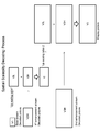
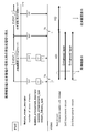
- FIG. 1 shows a configuration example of an image transmission / reception system 10 as an embodiment.
- the image transmission / reception system 10 includes a broadcasting station 100 and a receiver 200.
- the broadcasting station 100 transmits a transport stream TS as a container on a broadcast wave.
- the transport stream TS includes a basic video stream that includes image data of the lowest layer that configures the scalable encoded image data, and image data of layers other than the lowest layer that configures the scalable encoded image data, respectively.
- a predetermined number of extended video streams are included.
- the transport stream TS includes only a basic video stream that includes image data of a conventional image as basic image data.
- FIG. 2A shows image data of an HD image having an effective pixel number of 1920 * 1080 as image data of a conventional image.
- FIG. 2B shows 4K image data in which the number of effective pixels is doubled horizontally and vertically with respect to HD (High-Definition) as spatially ultra-high resolution image data.
- FIG. 2 (c) shows 8K image data that is four times as large as the number of effective pixels in the horizontal and vertical directions with respect to HD, as spatially ultra-high resolution image data.
- FIG. 3A shows 60 fps image data having a frame frequency of 60 Hz as conventional image data.
- FIG. 3B shows 120 fps image data having a frame frequency of 120 Hz as temporally ultra-high resolution image data.
- FIG. 3C shows 240 fps image data having a frame frequency of 240 Hz as temporally ultra-high resolution image data.
- FIG. 4 shows an example of spatial resolution scalability.
- 8K image data S-8K is handled as spatially ultra-high resolution image data.
- the transmission side encoding side
- the image data S-8K is subjected to a downsampling process of 1 / ⁇ times, here 1/2 times, in the downsampling unit 301 to generate 4K image data S-4K.
- the downsampling unit 302 performs a downsampling process of 1 / ⁇ times, here 1/2 times, on the image data S-4K to generate HD image data S-HD.
- the image data S-HD is subjected to up-sampling processing of ⁇ times, here doubled, in the up-sampling unit 303 to generate 4K image data S-4K_L.
- the 4K image data S-4K_L is obtained by performing a downsampling process and an upsampling process on the image data S-4K, and lacks a 4K level high frequency component.
- the image data S-4K_L is subtracted from the image data S-4K to generate a 4K level high frequency component S-4K_H.
- the upsampling unit 305 subjects the image data S-4K to ⁇ -times, here twice, upsampling processing to generate 8K image data S-8K_L.
- the 8K image data S-8K_L is obtained by performing a downsampling process and an upsampling process on the image data S-8K, and lacks an 8K level high frequency component.
- the image data S-8K_L is subtracted from the image data S-8K to generate an 8K level high frequency component S-8K_H.
- Image data S-HD constitutes image data of the first layer (the lowest layer).
- the image data S-HD is encoded by the video encoder 307, whereby a basic video stream St1 is obtained. This basic video stream St1 is temporarily stored in the encode buffer 308.
- the high-frequency component S-4K_H at the 4K level constitutes image data of the second hierarchy.
- the high-frequency component S-4K_H is encoded by the video encoder 309, whereby the first extended video stream St2 is obtained. This first extended video stream St2 is temporarily stored in the encode buffer 310.
- the 8K level high frequency component S-8K_H constitutes the third layer image data.
- the high-frequency component S-8K_H is encoded by the video encoder 311 to obtain a second extended video stream St3.
- This second extended video stream St3 is temporarily stored in the encode buffer 312.
- the basic video stream St1, the first extended video stream St2, and the second extended video stream St3 are combined by the multiplexer 313, and the combined stream is transmitted to the receiving side.
- the demultiplexer 351 separates the basic video stream St1, the first extended video stream St2, and the second extended video stream St3 from the combined stream.
- the basic video stream St1 is temporarily stored in the decode buffer 352.
- HD image data S-HD is obtained as the image data of the first layer (lowest layer). With this image data S-HD, an HD image can be displayed.
- the first extended video stream St2 is temporarily stored in the decode buffer 354. Then, the first extended video stream St2 is decoded by the decoder 355, thereby obtaining a 4K level high-frequency component S-4K_H as the second-layer image data. Further, the upsampling unit 356 performs ⁇ -sampling, and here twice, upsampling processing on the image data S-HD to generate 4K image data S-4K_L. In the adder 357, the 4K high-frequency component S-4K_H is added to the 4K image data S-4K_L to obtain 4K image data S-4K. With this image data S-4K, a 4K image can be displayed.
- the second extended video stream St3 is temporarily stored in the decode buffer 358. Then, the second extended video stream St3 is decoded by the decoder 359, whereby an 8K-level high-frequency component S-8K_H is obtained as image data of the third layer. Further, the upsampling unit 360 performs ⁇ -sampling, and here twice, the upsampling process on the image data S-4K, thereby generating 8K image data S-8K_L. The adder 361 adds the 8K level high frequency component S-8K_H to the 8K image data S-8K_L to obtain 8K image data S-4K. With this image data S-8K, an 8K image can be displayed.
- FIG. 5 shows a specific configuration example on the receiving side (decoding side) in the spatial resolution scalability described above.
- this structural example has shown the case of 2 layers (1st hierarchy, 2nd hierarchy).
- the basic video stream St1 is subjected to entropy decoding processing by the entropy decoding unit 353a, and is subjected to inverse quantization processing by the quantization decoding unit 353b. Further, the data after the inverse quantization processing is returned from the frequency axis data to the time axis data by the frequency conversion decoder 353c to obtain data D1 (n).
- image data S-HD (n-1) one frame before obtained from the frame buffer 353d is subjected to motion compensation processing by the motion compensation unit 353e to the data D1 (n) after the frequency conversion decoding. It is added after.
- the adder 353f obtains HD image data S-HD (n) of the current frame.
- the first extended video stream St2 is subjected to entropy decoding processing by the entropy decoding unit 355a and subjected to inverse quantization processing by the quantizing decoding unit 355b. Further, the data after the inverse quantization processing is returned from the frequency axis data to the time axis data by the frequency conversion decoder 355c to obtain data D2 (n).
- the high-frequency component S-4K_H (n-1) one frame before obtained from the frame buffer 355d is motion-compensated by the motion compensation unit 355e on the data D2 (n) after the frequency conversion decoding. It is added after. From this adder 355f, the 4K level high frequency component S-4K_H (n) of the current frame is obtained. Further, the upsampling unit 356 performs ⁇ -sampling, and here, doubles upsampling processing on the image data S-HD (n) to generate 4K image data S-4K_L (n). The adder 357 adds the 4K level high frequency component S-4K_H (n) to the 4K image data S-4K_L (n) to obtain 4K image data S-4K (n) of the current frame.
- FIG. 6 shows an example of a spatial resolution scalability decoding process.
- a basic video stream (Base stream) including image data of the first layer (the lowest layer).
- the first extended video stream (1st enhancement stream) including the second layer image data (high frequency component) and the second extended video stream including the third layer image data (high frequency component).
- (2nd enhancement stream) exists.
- the spatial resolution of the basic video stream is multiplied by 'Up scaling ratio 1' by the first extended video stream, and further increased by 'Up scaling ratio 2' by the second extended video stream. It is.
- the basic video stream is decoded to obtain the first layer image data V1.
- image data V2L in which the horizontal and vertical resolutions are each multiplied by 'Up scaling ratio 1' is obtained.
- the first extension video stream is decoded to obtain the second layer image data V2H.
- the image data V2L and V2H are added to obtain image data V2 in which the horizontal and vertical resolutions of the image data V1 are each multiplied by 'Up scaling ratio 1'.
- image data V3L in which the horizontal and vertical resolutions are multiplied by 'Up scaling ratio 2', respectively, is obtained.
- the second extended video stream is decoded to obtain the third layer image data V3H.
- the image data V3L and V3H are added to obtain display image data V3 in which the horizontal and vertical resolutions are multiplied by 'Up scaling‘ratio 2' with respect to the image data V2.
- FIG. 7 shows an example of temporal resolution scalability.
- image data S-120 of 120 fps is handled as temporally ultra-high resolution image data.
- This image data S-120 is separated into two layers, a first layer (lowest layer) and a second layer.
- the first layer image data (even-frame image data) is encoded, for example, as shown in FIG. 7B, to generate a basic video stream St1.
- the basic video stream St1 includes an I picture (IntraInpicture), a P picture (Predictive picture), and a B picture (Bi-directional predictive picture).
- the I picture does not refer to other pictures, and the P picture and B picture refer only to the I picture or P picture in the basic video stream St1. Therefore, this basic video stream St1 can be decoded only by this stream.
- the second layer image data (odd frame image data) is encoded, for example, as shown in FIG. 7C, to generate the first extended video stream St2.
- the first extended video stream St2 is composed of a P picture and a B picture.
- the P picture and the B picture refer not only to the P picture in the first extended video stream St2, but also to the I picture, the P picture, and the B picture in the basic video stream St1. Therefore, the first extended video stream St2 requires the decoding result of the basic video stream St1 as well as this stream.
- B picture of the first extended video stream St2 shown in FIG. 7C is indicated by “B”
- B picture of the basic video stream St1 shown in FIG. 7B is “Br”. It is shown. “B” represents a B picture that is not referenced from other pictures, and “Br” represents a B picture that is referenced from other pictures.
- the basic video stream St1 and the first extended video stream St2 described above are sent from the transmission side (encoding side) to the reception side (decoding side).
- 60 fps image data S-60 can be obtained by decoding the basic video stream St1.
- 120 fps image data S-120 can be obtained by decoding and synthesizing both the basic video stream St1 and the first extended video stream St2.
- FIG. 8 shows an example of decoding when the basic video stream St1 and the first extended video stream St2 described above are sent.
- St1 of the basic video stream the 0th frame I picture (I_0), the sixth frame P picture (P_6), the second frame B picture (Br_2), the fourth frame B picture (Br_4),... Decoding processing is performed in the order of. Note that the arrows in the figure indicate the reference relationship of pictures.
- the P picture (P_1) of the first frame, the P picture (P_7) of the seventh frame, the B picture (B_3) of the third frame, and the B picture (B_5) of the fifth frame ),... are decoded in this order.
- the arrows in the figure indicate the reference relationship of pictures.
- the first extended video stream St2 is decoded in this way, whereby image data S-120 of 120 fps is obtained.
- FIG. 9 shows a specific configuration example on the receiving side (decoding side) in the above-described time resolution scalability.
- this structural example has shown the case of 2 layers (1st hierarchy, 2nd hierarchy).
- the basic video stream St1 is subjected to entropy decoding processing by the entropy decoding unit 403a, and inverse quantization processing is performed by the quantizing decoding unit 403b. Further, the data after the inverse quantization processing is returned from the frequency axis data to the time axis data by the frequency conversion decoder 403c, and the decoded data D1 (n) of the current frame is obtained.
- the adder 403f the image data of the reference picture obtained from the frame buffer 403d is added to the decoded data D1 (n) after the motion compensation unit 403e performs motion compensation processing.
- the adder 403f obtains 60 fps image data S-60 (n) of the current frame.
- the first extended video stream St2 is subjected to entropy decoding processing by the entropy decoding unit 405a, and inverse quantization processing is performed by the quantizing decoding unit 405b. Further, the data after the inverse quantization processing is returned from the frequency axis data to the time axis data by the frequency conversion decoder 405c, and the decoded data D2 (n) of the current frame is obtained.
- the image data of the reference picture obtained from the frame buffer 403d or the frame buffer 405d is added to the decoded data D2 (n) after the motion compensation unit 405e performs motion compensation processing.
- 60 fps image data S-60 (n) ′ of the current frame is obtained.
- the synthesizing unit 406 synthesizes the 60 fps image data S-60 (n) ′ with the 60 fps image data S-60 (n) to obtain 120 fps image data S-120.
- One or more video streams are inserted into one or more video elementary streams and transmitted. That is, the transport stream TS includes one or a plurality of video elementary streams.
- the transport stream TS includes one or a plurality of video elementary streams.
- FIG. 10 shows an example of a decoding process for temporal resolution scalability. Note that the arrows in the figure indicate the referenced direction of the picture.
- a basic video stream (Base stream) including image data of the first layer (the lowest layer).
- a first extended video stream (1st enhancement stream) including image data of the second layer and a second extended video stream (2nd enhancement stream) including image data of the third layer.
- the frame display frequency of the basic video stream is doubled by the first extended video stream and further doubled by the second extended video stream.
- the enhanced layer picture insertion is 1 picture, and the first extended video stream and the second extended video Between the stream, one picture is inserted in the enhanced layer.
- Each picture of the basic video stream is decoded with reference to only the pictures in the basic video stream.
- Each picture of the first extended video stream is decoded with reference to a picture in the basic video stream.
- Each picture of the second extended video stream is decoded with reference to the pictures in the basic video stream and the first extended video stream.
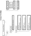
- FIGS. 11A and 11B show an example of a video elementary stream including encoded data of pictures of a plurality of video streams (substreams).
- encoded data of pictures of each substream is sequentially arranged.
- the encoded data of the first substream picture is composed of “SPSSP ⁇ Coded Slice”
- the encoded data of the second and subsequent substream pictures is composed of “Subset SPS ⁇ Coded Slice”.
- this example is an example in which MPEG4-AVC encoding is performed, but other encoding schemes are also applicable.
- the hexadecimal numbers in the figure indicate “ ⁇ NAL unit type”.
- FIG. 11A shows an example in which “SubstreamSubSeparation Marker” is not arranged between the encoded data of the pictures of each substream.
- FIG. 12 shows an example in which the first transmission mode and the second transmission mode are alternately continued and there is no identification information (signaling) for mode identification.
- Period A and period C indicate a period in the first transmission mode
- period B indicates a period in the second transmission mode.
- Each period represents, for example, a program unit or a scene unit.
- the basic video stream has a configuration in which a predetermined number of access units (AUs) are continued with SPS at the head.
- the extended video stream has a configuration in which a predetermined number of access units (AU) are continued with a subset SPS (SSSPS) at the head.
- the access unit (AU) is composed of “PPS,“ Substream ”SEIs,“ Coded ”Slice”.
- the extended video stream is not supplied to the reception buffer of the receiver at the timing of switching from the period A to the period B, whether extra time is required for arrival due to the circumstances of the encoder or the transmission path, or the extended video It is unclear as a receiver whether the stream encoding is interrupted and only the basic video stream is present. In that case, the buffer on the receiver side may wait longer than necessary, which can result in underflow.
- the receiver determines, for example, by changing the display mode from the ultra-high resolution image to the basic image (conventional image) by comparing with a preset timeout time. .
- the receiver determines, for example, by changing the display mode from the ultra-high resolution image to the basic image (conventional image) by comparing with a preset timeout time. .
- it takes a long processing time, and it is difficult to make an instantaneous determination. That is, it is possible to accurately cope with a change in stream configuration, that is, a dynamic change in delivery contents, and correct stream reception cannot be performed.
- mode identification information (signaling) synchronized with transmission mode switching is supplied, and the receiver detects the signal, thereby instantly determining the transmission mode switching time point. It is necessary to be able to do it.
- identification information for identifying the first transmission mode and the second transmission mode is inserted into the video stream.
- Insertion of identification information is performed by, for example, the following “Method 1”, “Method 2”, or “Method 3”.
- the “method 1” indicates that the identification information “EHF” indicating that the video stream is in the first transmission mode or the second transmission mode (the extended video stream does not exist).
- the identification information “BCF” shown is inserted. That is, in the first transmission mode, the identification information “EHF” is inserted into the video stream, and in the second transmission mode, the identification information “BCF” is inserted into the video stream.
- “method 2” inserts identification information “EHF” indicating that the video stream is in the first transmission mode (existence of an extended video stream). That is, the identification information “EHF” is inserted into the video stream in the first transmission mode, and the identification information is not inserted into the video stream in the second transmission mode.
- Method 3 inserts identification information “BCF” indicating the second transmission mode in the video stream, as shown in FIG. That is, in the first transmission mode, the identification information is not inserted into the video stream, and in the second transmission mode, the identification information “BCF” is inserted into the video stream.
- identification information in the case of indicating the first transmission mode, that is, in the case of the identification information “EHF”, information indicating the number of extended video streams, information indicating the type of scalability extension, and the upper layer in the scalability extension Information on the scaling ratio at the time of synthesis is included.
- This identification information is inserted into, for example, the user data area of the picture header or sequence header of the video stream.
- This identification information is inserted at least in units of programs, scenes, picture groups, or pictures. Note that the examples shown in FIGS. 13, 14, and 15 described above are examples inserted in units of pictures.
- the reception side can appropriately switch the display processing of the ultra-high resolution image or the display processing of the conventional image according to the switching of the transmission mode.
- a resolution increase process is performed. Details of the identification information (“EHF”, “BCF”) will be described later.
- identification information for identifying whether the transmission stream TS is in the first transmission mode or the second transmission mode is inserted into the layer of the transport stream TS.
- This identification information is arranged at an optimum position in an event unit or in a temporally static or dynamic use case. For example, this identification information is inserted under a video elementary loop (Video ES loop) of a program map table (PMT: Program Map Table) included in the transport stream TS.
- PMT Program Map Table
- information indicating the number of extended video streams, information indicating the type of scalability extension, information indicating whether a predetermined number of extended video streams are supplied as one video elementary stream, or the like is included. Details of this identification information will be described later.
- identification information for identifying the number of video elementary streams into which one or a plurality of video streams (substreams) are inserted is inserted into the transport stream TS layer.
- This identification information is arranged at an optimum position in an event unit or in a temporally static or dynamic use case. For example, this identification information is inserted under a program loop (Program_loop) of a program map table (PMT: Program Map Table) included in the transport stream TS.
- PMT Program Map Table
- the receiver 200 receives the transport stream TS transmitted from the broadcasting station 100 on a broadcast wave.
- the receiver 200 decodes a video stream (basic video stream, a predetermined number of extended video streams) included in the transport stream TS during the first transmission mode, and displays a display image of an ultra-high resolution image. Get the data.
- the receiver 200 decodes a video stream (basic video stream) included in the transport stream TS during the second transmission mode period, and acquires display image data of a conventional image.
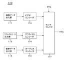
- FIG. 16 illustrates a configuration example of the transmission data generation unit 110 that generates the above-described transport stream TS in the broadcast station 100.
- the transmission data generation unit 110 includes an image data output unit 111, a video encoder 112, a graphics data output unit 113, a graphics encoder 114, an audio data output unit 115, an audio encoder 116, and a multiplexer 117. Yes.
- the image data output unit 111 outputs image data of a spatially or temporally high resolution image.
- the image data output unit 111 includes, for example, a camera that images a subject and outputs image data, or an image data reading unit that reads and outputs image data from a storage medium. Examples of the image data include 4K image data, 8K image data, and the like for displaying a spatial ultra-high resolution image.
- the image data corresponds to, for example, 120 fps image data, 240 fps image data, etc. for displaying a temporally ultra-high resolution image.
- the video encoder 112 performs a scalable encoding process on the image data output from the image data output unit 111, so that a basic video stream (substream) including image data in the lowest layer and a layer other than the lowest layer are processed. A predetermined number of extended video streams (substreams) each including hierarchical image data are generated. Each video stream (substream) is encoded by, for example, MPEG4-AVC, MPEG2 video, or the like. Then, the video encoder 112 generates one or a plurality of video elementary streams into which a basic video stream and a predetermined number of extended video streams are inserted, using a stream formatter (not shown) provided in the subsequent stage.
- a stream formatter not shown
- the video encoder 112 inserts identification information “EHF” indicating the first transmission mode into the basic video stream.
- the identification information “EHF” includes information indicating the number of extended video streams, information indicating the type of scalability extension, information on a scaling ratio when combining with an upper layer in scalability extension, and the like.
- FIG. 17 shows the order of encoded packets in a stream when a basic video stream and a predetermined number of extended video streams are inserted into one video elementary stream (Single PID). This example shows a case where there is one extended video stream. Although details will be described later, the identification information “EHF” is inserted into the basic video stream as an SEI message.
- FIG. 18 shows the order of encoded packets in each stream when each video stream of the basic video stream and a predetermined number of extended video streams is inserted into one video elementary stream (Multiple PID). This example shows a case where there is one extended video stream.
- the graphics data output unit 113 outputs data of graphics (including subtitles as subtitles) to be superimposed on the image.
- the graphics encoder 114 generates a graphics stream (graphics elementary stream) including the graphics data output from the graphics data output unit 113.
- the graphics constitute superimposition information, and are, for example, a logo, subtitles, and the like.
- the graphics data is mainly bitmap data. Offset information indicating the superimposed position on the image is added to the graphics data. This offset information indicates, for example, offset values in the vertical and horizontal directions from the upper left origin of the image to the upper left pixel of the graphics superimposed position.
- the standard for transmitting caption data as bitmap data is standardized and operated as “DVB_Subtitling” in DVB, which is a European digital broadcasting standard, for example.
- the audio data output unit 115 outputs audio data corresponding to the image data.
- the audio data output unit 115 is configured by, for example, a microphone or an audio data reading unit that reads and outputs audio data from a storage medium.
- the audio encoder 116 performs encoding such as MPEG-2 Audio or AAC on the audio data output from the audio data output unit 115 to generate an audio stream (audio elementary stream).
- the multiplexer 117 packetizes and multiplexes the elementary streams generated by the video encoder 112, the graphics encoder 114, and the audio encoder 116, and generates a transport stream TS.
- PTS Presentation Time Time Stamp
- PES Packetized Elementary Stream
- the multiplexer 117 inserts identification information for identifying whether it is in the first transmission mode or the second transmission mode in the layer of the transport stream TS.
- this identification information indicates the first transmission mode.
- This identification information is inserted, for example, under the video elementary loop (Video ES loop) of the program map table (PMT) included in the transport stream TS.
- the multiplexer 117 inserts identification information for identifying the number of video elementary streams into which one or more video streams (substreams) are inserted into the layer of the transport stream TS.
- this identification information indicates “1” or “the number of extended video streams + 1”.
- This identification information is inserted, for example, under the program loop (Program_loop) of the program map table (PMT) included in the transport stream TS.
- the image data output unit 111 outputs image data of a conventional image, for example, an HD image.
- the video encoder 112 performs encoding such as MPEG4-AVC or MPEG2 video on the image data output from the image data output unit 111 to generate a basic video stream (substream). Then, the video encoder 112 generates one video elementary stream in which the basic video stream is inserted, by a stream formatter (not shown) provided in the subsequent stage.
- the video encoder 112 inserts identification information “BCF” indicating the second transmission mode into the basic video stream.
- the graphics data output unit 113 the graphics encoder 114, the audio data output unit 115, and the audio encoder 116 are the same as those in the first transmission mode.
- the multiplexer 117 packetizes and multiplexes the elementary streams generated by the video encoder 112, the graphics encoder 114, and the audio encoder 116, and generates a transport stream TS.
- PTS Presentation Time Time Stamp
- PES Packetized Elementary Stream
- the multiplexer 117 inserts identification information for identifying whether it is in the first transmission mode or the second transmission mode in the layer of the transport stream TS.
- this identification information indicates the second transmission mode.
- This identification information is inserted, for example, under the video elementary loop (Video ES loop) of the program map table (PMT) included in the transport stream TS.
- the multiplexer 117 inserts identification information for identifying the number of video elementary streams into which one or more video streams (substreams) are inserted into the layer of the transport stream TS.
- this identification information indicates “1”.
- This identification information is inserted, for example, under the program loop (Program_loop) of the program map table (PMT) included in the transport stream TS.
- the image data of the super-high-resolution spatial or temporal image output from the image data output unit 111 is supplied to the video encoder 112.
- the video encoder 112 performs scalable coding processing on the image data, and includes a basic video stream (substream) including image data of the lowest layer and image data of layers other than the lowest layer, respectively. A predetermined number of extended video streams (substreams) are generated. Then, the video encoder 112 generates one or a plurality of video elementary streams into which the basic video stream and a predetermined number of extended video streams are inserted. This video elementary stream is supplied to the multiplexer 117. Also, in the video encoder 112, when the above-described “method 1” or “method 2” is adopted, identification information “EHF” indicating that the transmission mode is the first transmission mode is inserted into the basic video stream. (See FIGS. 13 and 14).
- graphics data (including subtitle data) output from the graphics data output unit 113 is supplied to the graphics encoder 114.
- the graphics encoder 114 generates a graphics stream (graphics elementary stream) including graphics data. This graphics stream is supplied to the multiplexer 115.
- the audio data output from the audio data output unit 115 is supplied to the audio encoder 116.
- the audio data is encoded by MPEG-2 Audio, AAC or the like, and an audio stream (audio elementary stream) is generated. This audio stream is supplied to the multiplexer 117.
- the elementary streams supplied from the encoders are packetized and multiplexed to generate a transport stream TS.
- a PTS is inserted into each PES header for synchronous reproduction on the receiving side.
- identification information for identifying whether the transmission mode is the first transmission mode or the second transmission mode is inserted under the video elementary loop (Video ES loop) of the PMT.
- identification information for identifying the number of video elementary streams is inserted under the program loop of the PMT.
- Image data of a conventional image, for example, an HD image, output from the image data output unit 111 is supplied to the video encoder 112.
- the video encoder 112 performs encoding such as MPEG4-AVC or MPEG2 video on the image data, and generates a basic video stream (substream).
- the video encoder 112 generates one video elementary stream into which the basic video stream is inserted.
- the identification information “BCF” indicating the second transmission mode is inserted into the basic video stream. (See FIGS. 13 and 15).
- the elementary streams generated by the video encoder 112, the graphics encoder 114, and the audio encoder 116 are packetized and multiplexed to generate a transport stream TS.
- a PTS is inserted into each PES header for synchronous reproduction on the receiving side.
- identification information for identifying whether the transmission mode is the first transmission mode or the second transmission mode is inserted under the video elementary loop (Video (ES loop) of the PMT.
- the In the multiplexer 117 for example, identification information for identifying the number of video elementary streams is inserted under the program loop of the PMT.
- identification information (“EHF”, “BCF”) for identifying the first transmission mode and the second transmission mode is inserted into the video stream.
- EHF EHF
- BCF encoding structure
- the identification information is stored in the access unit (AU). Is inserted as an SEI message (Enhancement scalability SEI message).
- FIG. 19A shows the top access unit of GOP (Group Of Pictures), and FIG. 19B shows the access unit other than the top of the GOP.
- the identification information (“EHF”, “BCF”) is inserted in GOP units
- “Enhancement scalability SEI message” is inserted only in the head access unit of the GOP.
- SEI messages other than “Enhancement scalability SEI message” correspond to the portions described as “conventional SEI” in FIGS. 17 and 18 described above.
- FIG. 20A shows a structure example (Syntax) of “Enhancement scalability SEI message”. “Uuid_iso_iec — 11578” has a UUID value indicated by “ISO / IEC 11578: 1996 Annex A.”. “Userdata_for_enhancement_scalability_data ()” is inserted into the “user_data_payload_byte” field.
- FIG. 20B shows a structural example (Syntax) of “userdata_for_enhancement_scalability_data ()”. In this, enhancement scalability data (enhancement_scalability_data ()) is inserted. “Userdata_id” is an identifier of enhancement scalability data indicated by unsigned 16 bits.
- FIG. 21 shows a structure example (Syntax) of enhancement scalability data (enhancement_scalability_data ()).
- FIG. 22 shows the contents (Semantics) of main information in the structural example.
- the 2-bit field of“ enhancement_scalability_type ” indicates the type of scalability extension. For example, “00” indicates non-scalability, “01” indicates spatial resolution scalability, and “10” indicates temporal resolution scalability.
- this 2-bit field is, for example, “01” or “10”.
- identification information “BCF” indicating the second transmission mode this 2-bit field is “00”. Therefore, it is possible to identify whether the transmission mode is the first transmission mode or the second transmission mode by the 2-bit field.
- “3-bit field of“ number_of_enhanced_streams ” indicates the number (number) of extended video streams. For example, “000” indicates 0 stream, “001” indicates 1 stream, “010” indicates 2 streams, and “011” indicates 3 streams.
- this 3-bit field indicates one stream or more.
- this 3-bit field indicates 0 stream.
- the 2-bit field of “enhancement_scalability_type” indicates spatial resolution scalability
- This 3-bit field indicates the spatial scaling ratio when synthesizing with the decoded picture (image) of the enhancement layer (enhancement layer), and after the decoding of the lower layer (lower layer) This represents a combination of a horizontal pixel ratio and a vertical pixel ratio for scaling a picture (see FIG. 6).
- “000” indicates no scaling.
- “001” indicates that the upscaling ratio is 50% (3/2 times) in both horizontal and vertical directions.
- “010” indicates that the upscaling ratio is 100% (doubled) in both horizontal and vertical directions.
- “011” indicates that the upscaling ratio is 150% (5/2 times) in both the horizontal and vertical directions.
- the 2-bit field of “enhancement_scalability_type” indicates temporal resolution scalability
- This 3-bit field indicates the temporal scaling ratio when combining with the decoded picture of the enhancement layer (enhancement layer), and the decoded picture (image) of the lower layer (lower layer) ) Indicates the number of pictures in the enhanced layer (see FIG. 10).
- “000” indicates that there is no enhancement layer picture insertion. “001” indicates that the enhancement layer picture insertion is one picture, “010” indicates that the enhancement layer picture insertion is two pictures, and “011” indicates that the enhancement layer picture insertion is three pictures. It shows that.
- FIG. 23 shows a structural example (Syntax) of a scalable enhancement descriptor (Scalable_enhancement_descriptor) as the identification information.
- FIG. 24 shows the contents (Semantics) of main information in the structural example.
- This scalable enhancement descriptor is inserted only when, for example, in the first transmission mode. Therefore, the presence of this descriptor makes it possible to identify the presence of the first transmission mode in the transport stream TS layer. Conversely, the absence of this descriptor makes it possible to identify the second transmission mode in the transport stream TS layer. Identification can be made.
- the 8-bit field of“ scalable_enhancement_tag ” indicates the descriptor type, and here indicates that it is a scalable enhancement descriptor.
- the 8-bit field of “scalable_enhancement_length” indicates the length (size) of the descriptor, and indicates the number of subsequent bytes as the descriptor length.
- Scalable_enhancement_type indicates the type of scalability extension. For example, “01” indicates spatial resolution scalability, and “10” indicates temporal resolution scalability.
- the 1-bit field of “stream_delivery_type” indicates the video elementary stream configuration to which the basic and extended video streams are supplied. “1” indicates that each video stream is supplied as one video elementary stream, and “0” indicates that each video stream is supplied as a plurality of video elementary streams.
- “3-bit field of“ number_of_enhanced_streams ” indicates the number (number) of extended video streams. For example, “000” indicates 0 stream, “001” indicates 1 stream, “010” indicates 2 streams, and “011” indicates 3 streams.
- FIG. 25A shows a structural example (Syntax) of a multiple stream descriptor (Multiple_stream_descriptor) as the identification information.
- the 8-bit field of “multiple_stream_tag” indicates the descriptor type, and here indicates that it is a multiple stream descriptor.
- the 8-bit field of “multiple_stream_length” indicates the length (size) of the descriptor, and indicates the number of subsequent bytes as the descriptor length.
- the 3-bit field of“ number_of_video_streams ” indicates the number of video elementary streams. For example, as shown in FIG. 25B, “001” indicates one stream, “010” indicates two streams, “011” indicates three streams, and “100” indicates four streams. In the case of the first transmission mode, this 3-bit field indicates one stream or more. On the other hand, in the second transmission mode, this 3-bit field indicates only one stream.
- FIG. 26 shows a configuration example of the transport stream TS.
- the basic video stream, or the basic video stream and a predetermined number of extended video streams are inserted and transmitted in one video elementary stream (Single PID) is shown. That is, in this one video element stream, the basic video stream and a predetermined number of extended video streams are inserted in the first transmission mode, and only the basic video stream is inserted in the second transmission mode. Has been inserted.
- the transport stream TS includes a PES packet “PID1: video PES1” of one video elementary stream.
- Identification information (“EHF”, “BCF”) for identifying the first transmission mode and the second transmission mode is included in the SEI message in the basic video stream (substream) inserted into the video elementary stream. (Enhancement scalability SEI message) is inserted (see FIG. 21).
- the transport stream TS includes a PMT (Program Map Table) as PSI (Program Specific Information).
- PSI Program Specific Information
- the PMT there is an elementary loop having information related to each elementary stream.
- a video elementary loop (Video ES loop).
- information such as a stream type and a packet identifier (PID) is arranged corresponding to the above one video elementary stream, and information related to the video elementary stream is described.
- a descriptor is also arranged.
- a scalable enhancement descriptor (Scalable_enhancement_descriptor) is inserted in association with the one video elementary stream described above (see FIG. 23). Also, a multiple stream descriptor (Multiple_stream_descriptor) is inserted under the program loop (Program loop) of the PMT (see FIG. 25). Note that, as described above, the scalable enhancement descriptor is inserted only when, for example, in the first transmission mode.
- FIG. 27 also shows a configuration example of the transport stream TS. Also in this example, for the sake of simplification of the drawings, illustrations of portions relating to audio and graphics are omitted.
- This example shows an example in which a basic video stream and a predetermined number of extended video streams are inserted and transmitted in separate video elementary streams (Multiple PID).
- This example shows an example in which there are two extended video streams.
- the PES packet “PID1: video PES1” of the video elementary stream into which the basic video stream (substream) is inserted is included.
- identification information (“EHF”, “BCF”) for identifying the first transmission mode and the second transmission mode is inserted as an SEI message (Enhancement scalability SEI message) (See FIG. 21).
- a PES packet “PID3: video PES3” of the video elementary stream is included.
- the transport stream TS includes a PMT (Program Map Table) as PSI (Program Specific Information).
- PSI Program Specific Information
- the PMT there is an elementary loop having information related to each elementary stream.
- a video elementary loop (Video ES loop).
- information such as a stream type and a packet identifier (PID) is arranged for each video elementary stream, and a descriptor describing information related to the video elementary stream is also arranged. .
- a scalable enhancement descriptor (Scalable_enhancement_descriptor) having the same content is inserted under the video elementary loop (Video ES loop) of the PMT in association with each of the above video elementary streams (see FIG. 23).
- a scalable enhancement descriptor Scalable_enhancement_descriptor
- a multiple stream descriptor (Multiple_stream_descriptor) is inserted under the program loop (Program loop) of the PMT (see FIG. 25). Note that, as described above, the scalable enhancement descriptor is inserted only when, for example, in the first transmission mode.
- FIG. 28 illustrates a configuration example of the receiver 200.
- the receiver 200 includes a CPU 201, a flash ROM 202, a DRAM 203, an internal bus 204, a remote control receiver (RC receiver) 205, and a remote control transmitter (RC transmitter) 206.
- the receiver 200 also includes an antenna terminal 211, a digital tuner 212, a transport stream buffer (TS buffer) 213, and a demultiplexer 214.
- the receiver 200 includes a coded buffer 215, a video decoder 216, a basic stream decoded buffer 217, an extended stream decoded buffer 218, a synthesis processing unit 219, a video RAM 220, and a resolution up processing unit 221. , A superimposing portion 2222 is provided.
- the receiver 200 includes a coded buffer 231, a graphics decoder 232, a pixel buffer 233, a scaler 234, a coded buffer 241, an audio decoder 242, and a channel mixing unit 243.
- the CPU 201 controls the operation of each unit of receiver 200.
- the flash ROM 202 stores control software and data.
- the DRAM 203 constitutes a work area for the CPU 201.
- the CPU 201 develops software and data read from the flash ROM 202 on the DRAM 203 and activates the software to control each unit of the receiver 200.
- the RC receiving unit 205 receives a remote control signal (remote control code) transmitted from the RC transmitter 206 and supplies it to the CPU 201.
- CPU201 controls each part of receiver 200 based on this remote control code.
- the CPU 201, flash ROM 202, and DRAM 203 are connected to the internal bus 204.
- the antenna terminal 211 is a terminal for inputting a television broadcast signal received by a receiving antenna (not shown).
- the digital tuner 212 processes the television broadcast signal input to the antenna terminal 211 and outputs a predetermined transport stream (bit stream data) TS corresponding to the user's selected channel.
- the transport stream buffer (TS buffer) 213 temporarily accumulates the transport stream TS output from the digital tuner 212.
- the transport stream TS includes one or more video elementary streams, a graphics elementary stream, and an audio elementary stream. Then, the following substreams are inserted into the one or more video elementary streams in the first transmission mode and in the second transmission mode.
- the basic video stream includes image data of the lowest layer constituting scalable encoded image data (image data of a spatially or temporally ultra-high resolution image).
- the predetermined number of extended video streams respectively include image data of layers other than the lowest layer constituting the scalable encoded image data.
- the basic video stream includes image data of a conventional image (for example, HD resolution, 25 fps, 30 fps image, etc.) as basic image data.
- an SEI message (Enhancement scalability SEI message) as identification information (“EHF”, “BCF”) for identifying the first transmission mode and the second transmission mode is inserted into the basic video stream.
- EHF identification information
- BCF identification information
- a scalable enhancement descriptor Scalable_enhancement_descriptor
- Multiple_stream_descriptor is inserted in the transport stream TS layer as identification information for identifying the number of video elementary streams (see FIG. 25).
- the demultiplexer 214 extracts video, graphics, and audio elementary streams from the transport stream TS temporarily stored in the TS buffer 213. Further, the demultiplexer 214 extracts the above-described scalable enhancement descriptor and multiple stream descriptor from the transport stream TS, and sends them to the CPU 201.
- the CPU 201 controls processing such as decoding in the receiver 200 based on information included in these descriptors. For example, the scalable enhancement descriptor under the video elementary loop (Video ES loop) and the video elementary stream (PES stream) associated therewith as many as the number of video elementary streams included in the multiple stream descriptor. Control to decode.
- Video ES loop Video ES loop
- PES stream video elementary stream
- the coded buffer 215 temporarily stores one or more video elementary streams extracted by the demultiplexer 214.
- the video decoder 216 takes out and decodes one or a plurality of video streams (substreams) inserted into the video elementary stream stored in the coded buffer 215 under the control of the CPU 201.
- a basic video stream and a predetermined number of extended video streams are extracted and decoded.
- image data of the lowest layer constituting the scalable encoded image data for example, image data such as HD resolution, 25 fps, and 30 fps images
- image data in a layer other than the lowest layer constituting the scalable encoded image data can be obtained.
- image data of a conventional image for example, HD resolution, 25 fps, 30 fps image, etc.
- the video decoder 216 extracts the SEI message (Enhancement scalability SEI message) inserted in the basic video stream and sends it to the CPU 201.
- the CPU 201 identifies whether it is in the first transmission mode or the second transmission mode based on the mode information in this SEI message.
- Each unit of the receiver 200 is controlled so that the corresponding processing is performed. For example, when the mode switching is identified in the transport stream TS layer due to the presence or absence of the scalable enhancement descriptor, the process switching is performed when the mode switching is identified by the mode information in the subsequent SEI message. Is done.
- the basic stream decoded buffer 217 temporarily stores image data obtained by decoding the basic video stream by the video decoder 216.
- This image data is image data of the lowest layer constituting scalable encoded image data when in the first transmission mode, and is image data of a conventional image when in the second transmission mode.
- the extended stream decoded buffer 218 temporarily stores each piece of image data obtained by decoding a predetermined number of extended video streams by the video decoder 216. Each piece of image data is obtained only when in the first transmission mode, and is image data in a layer other than the lowest layer constituting the scalable encoded image data.
- the composition processing unit 219 performs processing only when in the first transmission mode. This composition processing unit 219 performs composition processing between the image data of the lowest hierarchy stored in the basic stream decoded buffer 217 and the image data of a hierarchy other than the lowest hierarchy stored in the extended stream decoded buffer 218. To generate display image data Va for an ultra-high resolution image (see FIGS. 6 and 10).
- the synthesis processing unit 219 refers to information such as a scaling ratio included in the SEI message (Enhancement scalability SEI message) according to the type of scalability extension, and performs a spatial resolution scalability or temporal resolution scalability synthesis process. .
- the resolution enhancement processing unit 221 performs processing only when in the second transmission mode.
- the resolution increasing processing unit 221 performs resolution increasing processing on the image data of the conventional image stored in the basic stream decoded buffer 217, and the resolution of the image data Va for display of the ultra-high resolution image described above. Display image data Vb having the same resolution is generated.
- the spatial resolution is increased
- the frame frequency is increased.
- the video RAM 220 When the video RAM 220 is in the first transmission mode, the video RAM 220 temporarily stores the image data Va generated by the composition processing unit 219. Further, when the video RAM 220 is in the second transmission mode, the video RAM 220 temporarily stores the image data Vb generated by the resolution increase processing unit 221.
- the coded buffer 231 temporarily stores the graphics stream extracted by the demultiplexer 214.
- the graphics decoder 232 performs processing opposite to that of the graphics encoder 114 (see FIG. 16) of the transmission data generation unit 110 described above. That is, the graphics decoder 232 performs decoding processing on the graphics stream stored in the coded buffer 231 to obtain decoded graphics data (including subtitle data).
- the graphics decoder 232 generates graphics bitmap data to be superimposed on the image data based on the graphics data.
- the pixel buffer 233 temporarily stores graphics bitmap data generated by the graphics decoder 232.
- the scaler 234 adjusts the size of the graphics bitmap data stored in the pixel buffer 233 so as to correspond to the size of the display image data.
- the superimposing unit 222 superimposes the scaled graphics bitmap data on the display image data Va and Vb stored in the video RAM 220 to obtain final display image data.
- the coded buffer 241 temporarily stores the audio stream extracted by the demultiplexer 214.
- the audio decoder 242 performs processing reverse to that of the audio encoder 116 (see FIG. 16) of the transmission data generation unit 110 described above. That is, the audio decoder 242 performs decoding processing on the audio stream stored in the coded buffer 241 to obtain decoded audio data.
- the channel mixing unit 243 obtains audio data of each channel for realizing, for example, 5.1ch surround with respect to the audio data obtained by the audio decoder 242.
- a television broadcast signal input to the antenna terminal 211 is supplied to the digital tuner 212.
- the television broadcast signal is processed, and a predetermined transport stream TS corresponding to the user's selected channel is output.
- This transport stream TS is temporarily stored in the TS buffer 213.
- the transport stream TS includes one or more video elementary streams, a graphics elementary stream, and an audio elementary stream. Then, a basic video stream and a predetermined number of extended video streams are inserted into the one or more video elementary streams.
- each elementary stream of video, graphics, and audio is extracted from the transport stream TS temporarily stored in the TS buffer 213.
- the demultiplexer 214 extracts a scalable enhancement descriptor (Scalable_enhancement_descriptor) and a multiple stream descriptor (Multiple_stream_descriptor) from the transport stream TS, and sends them to the CPU 201.
- the CPU 201 controls processing such as decoding in the receiver 200 based on information included in these descriptors.
- the one or more video elementary streams extracted by the demultiplexer 214 are supplied to the coded buffer 215 and temporarily accumulated.
- the video decoder 216 under the control of the CPU 201, one or a plurality of video streams (substreams) inserted in the video elementary stream stored in the coded buffer 215 are extracted and decoded.
- a basic video stream and a predetermined number of extended video streams are extracted and decoded.
- image data of the lowest layer for example, HD resolution, 25 fps, 30 fps image, etc.
- image data in a layer other than the lowest layer constituting the scalable encoded image data can be obtained.
- the SEI message (Enhancement scalability SEI ⁇ message) inserted in the basic video stream is extracted and sent to the CPU 201.
- the mode information in the SEI message identifies whether the transmission mode is the first transmission mode or the second transmission mode. In this case, it is identified that the transmission mode is the first transmission mode, and each part of the receiver 200 is controlled so that processing according to the first transmission mode is performed.
- the image data of the lowest layer constituting the scalable encoded image data obtained by the video decoder 216 is temporarily stored in the basic stream decoded buffer 217. Also, image data of a layer other than the lowest layer constituting the scalable encoded image data obtained by the video decoder 216 is temporarily stored in the extended stream decoded buffer 218.
- the composition processing unit 219 performs composition processing between the image data of the lowest hierarchy stored in the basic stream decoded buffer 217 and the image data of a hierarchy other than the lowest hierarchy stored in the extended stream decoded buffer 218. Done. In the synthesis processing unit 219, display image data Va for an ultra-high resolution image is generated. This display image data Va is temporarily stored in the video RAM 220.
- the graphics stream extracted by the demultiplexer 214 is supplied to the coded buffer 231 and temporarily accumulated.
- the graphics decoder 232 performs decoding processing of the graphics stream stored in the coded buffer 231 to obtain decoded graphics data (including subtitle data). Further, the graphics decoder 232 generates graphics bitmap data to be superimposed on the image data based on the graphics data.
- the graphics bitmap data generated by the graphics decoder 232 is supplied to the pixel buffer 233 and temporarily stored.
- the scaler 234 adjusts the size of the graphics bitmap data stored in the pixel buffer 233 so as to correspond to the size of the display image data Va.
- the superimposing unit 222 superimposes the scaled graphics bitmap data on the display image data Va stored in the video RAM 220 to obtain final display image data. By supplying the display image data to the display, a spatially or temporally super-high resolution image is displayed.
- the audio stream extracted by the demultiplexer 214 is supplied to the coded buffer 241 and temporarily accumulated.
- the audio decoder 242 performs a decoding process on the audio stream stored in the coded buffer 241 to obtain decoded audio data.
- the audio data is supplied to the channel mixing unit 243.
- the channel mixing unit 243 generates audio data of each channel for realizing, for example, 5.1ch surround with respect to the audio data. This audio data is supplied to, for example, a speaker, and audio output is performed in accordance with image display.
- a television broadcast signal input to the antenna terminal 211 is supplied to the digital tuner 212.
- the television broadcast signal is processed, and a predetermined transport stream TS corresponding to the user's selected channel is output.
- This transport stream TS is temporarily stored in the TS buffer 213.
- the transport stream TS includes one video elementary stream, a graphics elementary stream, and an audio elementary stream.
- a basic video stream is inserted into this one video elementary stream.
- each elementary stream of video, graphics, and audio is extracted from the transport stream TS temporarily stored in the TS buffer 213. Further, the demultiplexer 214 extracts a multiple stream descriptor (Multiple_stream_descriptor) from the transport stream TS and sends it to the CPU 201. In the CPU 201, processing such as decoding in the receiver 200 is controlled based on information included in the descriptor.
- a multiple stream descriptor Multiple_stream_descriptor
- One video elementary stream extracted by the demultiplexer 214 is supplied to the coded buffer 215 and temporarily accumulated.
- a basic video stream (substream) inserted in the video elementary stream stored in the coded buffer 215 is extracted and decoded.
- image data of a conventional image for example, HD resolution, 25 fps, 30 fps image, etc.
- This image data is temporarily stored in the basic stream decoded buffer 217.
- the SEI message (Enhancement scalability SEI ⁇ message) inserted in the basic video stream is extracted and sent to the CPU 201.
- the CPU 201 identifies whether it is in the first transmission mode or the second transmission mode based on the mode information in this SEI message. In this case, it is identified that the transmission mode is the second transmission mode, and each part of the receiver 200 is controlled so that processing according to the second transmission mode is performed.
- the resolution increasing process is performed on the image data of the conventional image stored in the basic stream decoded buffer 217, and is equivalent to the resolution of the display image data Va for the ultra-high resolution image described above.
- Display image data Vb having a resolution of 1 is generated.
- the spatial resolution is increased
- the frame frequency is increased.
- the graphics stream extracted by the demultiplexer 214 is supplied to the coded buffer 231 and temporarily accumulated.
- the graphics decoder 232 performs decoding processing of the graphics stream stored in the coded buffer 231 to obtain decoded graphics data (including subtitle data). Further, the graphics decoder 232 generates graphics bitmap data to be superimposed on the image data based on the graphics data.
- the graphics bitmap data generated by the graphics decoder 232 is supplied to the pixel buffer 233 and temporarily stored.
- the scaler 234 adjusts the size of the graphics bitmap data stored in the pixel buffer 233 so as to correspond to the size of the display image data Vb.
- the superimposing unit 222 superimposes the scaled graphics bitmap data on the display image data Vb stored in the video RAM 220 to obtain final display image data.
- FIG. 29 shows an example of reception process switching control.
- a basic video stream and a predetermined number of extended video streams are inserted and supplied in one video elementary stream.
- the basic video stream includes image data (HD image data) in the lowest layer (first layer), and a predetermined number of extended video streams include images in a layer other than the lowest layer (enhanced layer). Contains data.
- the second transmission mode one video stream into which the basic video stream is inserted is supplied.
- “Number_of_video_streams” of a multiple stream descriptor (Multiple_stream_descriptor) inserted in the layer of the transport stream TS is a period of a high definition program (first transmission mode) and a period of a conventional program (second transmission mode). Both are set to “001”, indicating that the number of video elementary streams is one in any period.
- scalable_enhancement_type of the scalable enhancement descriptor (Scalable_enhancement_descriptor) inserted in the layer of the transport stream TS in the high-definition program (first transmission mode) is “01”, which indicates that the spatial resolution scalability is provided. It is. Further, “stream_delivery_type” of this descriptor is set to “1”, which indicates that the basic and extended video streams are supplied as one video elementary stream.
- the SEI message (Enhancement scalability SEI message) is inserted in the basic stream.
- “enhancement_scalability_type” included in the SEI message is “01” indicating that there is a spatial resolution scalability, indicating that it is a high definition program (first transmission mode). Identification is also possible.
- “enhancement_scalability_type” is “00”, so that it is possible to identify the period of the conventional program (second transmission mode).
- the reception process switching control in the receiver 200 is performed as follows.
- the layer of the transport stream TS is high due to the presence of the scalable enhancement descriptor (Scalable_enhancement_descriptor).
- Scalable_enhancement_descriptor the scalable enhancement descriptor
- a switch to a fine program (second transmission mode) is identified.
- “enhancement_scalability_type” of the SEI message (Enhancement scalability SEI message) inserted in the basic stream becomes “01”, and switching to the high definition program (second transmission mode) is identified in the video layer.
- Ta the reception process is switched from the conventional program (second transmission mode) to the high-definition program (first transmission mode).
- FIG. 30 shows an example of reception process switching control.
- a basic video stream and two extended video streams are inserted into three video elementary streams and supplied.
- the basic video stream includes image data (HD image data) of the lowest layer (first layer).
- the first extended video stream includes image data (high frequency component) of the second layer
- the second extended video stream includes image data (high frequency component) of the third layer.
- one video stream into which the basic video stream is inserted is supplied.
- “Number_of_video_streams” of the multiple stream descriptor (Multiple_stream_descriptor) inserted in the layer of the transport stream TS is set to “011” in the period of the high definition program (first transmission mode), and the number of video elementary streams Is shown to be three.
- “number_of_video_streams” is “001” in the period of the conventional program (second transmission mode), indicating that the number of video elementary streams is one.
- scalable_enhancement_type of the scalable enhancement descriptor (Scalable_enhancement_descriptor) inserted in the layer of the transport stream TS in the high-definition program (first transmission mode) is “01”, which indicates that the spatial resolution scalability is provided. It is.
- stream_delivery_type of this descriptor is set to “0”, which indicates that the basic and extended deostreams are supplied as a plurality of video elementary streams.
- the SEI message (Enhancement scalability SEI message) is inserted in the basic stream.
- “enhancement_scalability_type” included in the SEI message is “01” indicating that there is a spatial resolution scalability, indicating that it is a high definition program (first transmission mode). Identification is also possible.
- “enhancement_scalability_type” is “00”, so that it is possible to identify the period of the conventional program (second transmission mode).
- identification of program switching in the layer of the transport stream TS and program switching in the subsequent video layer are performed. Based on the identification, reception process switching control in the receiver 200 is performed.
- the basic video stream and the scalable encoded image data including the image data of the lowest layer configuring the scalable encoded image data are configured.
- a predetermined number of extended video streams each including image data of a layer other than the lowest layer are transmitted, and only the basic video stream including the basic image data is transmitted in the second transmission mode.
- identification information (“EHF”, “BCF”) for identifying the first mode and the second mode is inserted into the video stream.
- the receiving side can easily grasp whether the transmission mode is the first transmission mode or the second transmission mode on the basis of this identification information. It is possible to respond accurately and receive a correct stream.
- the processing switching is good on the receiving side. Can be done.
- the container is a transport stream (MPEG-2 TS)
- MPEG-2 TS transport stream
- the present technology can be similarly applied to a system configured to be distributed to receiving terminals using a network such as the Internet.
- the Internet distribution it is often distributed in a container of MP4 or other formats.
- containers of various formats such as transport stream (MPEG-2 TS) adopted in the digital broadcasting standard and MP4 used in Internet distribution correspond to the container.
- this technique can also take the following structures.
- a transmitter that transmits one or more video streams;
- a basic video stream including image data of the lowest layer constituting the scalable encoded image data and a predetermined number of extended video streams each including image data of a layer other than the lowest layer constituting the scalable encoded image data are transmitted.
- a transmission apparatus comprising: an identification information insertion unit that inserts identification information for identifying a first transmission mode and a second transmission mode for transmitting only a basic video stream including basic image data into the video stream.
- the identification information insertion unit In the first transmission mode, identification information indicating the first transmission mode is inserted into the video stream, and in the second transmission mode, the identification information is not inserted into the video stream.
- the identification information insertion unit In the first transmission mode, identification information indicating the first transmission mode is inserted into the video stream. In the second transmission mode, the video stream is inserted into the video stream in the second transmission mode.
- the transmission apparatus according to (1) wherein identification information indicating that there is a message is inserted.
- the identification information insertion unit In the first transmission mode the identification information is not inserted into the video stream, and in the second transmission mode, identification information indicating the second transmission mode is inserted into the video stream.
- the transmission device according to (1).
- (5) The identification information insertion unit The transmission apparatus according to any one of (1) to (4), wherein the identification information is inserted into the basic video stream at least in units of programs, scenes, picture groups, or pictures.
- the transmission unit In the first transmission mode the basic video stream and the predetermined number of extended video streams are inserted and transmitted in one or a plurality of video elementary streams. Any one of (1) to (5) Transmitter. (7) When the basic video stream and the predetermined number of extended video streams are inserted and transmitted in one video elementary stream, information indicating a stream boundary is arranged between the video streams. The transmitting device described. (8) The transmission device according to any one of (1) to (7), wherein the identification information includes information indicating the number of the extended video streams when indicating the first transmission mode. (9) The transmission apparatus according to any one of (1) to (8), wherein the identification information includes information indicating a type of scalability extension when indicating the first transmission mode.
- the identification information includes information on a scaling ratio at the time of combining with an upper layer in scalability extension. Any one of (1) to (9) The transmitting device according to 1. (11) The transmission unit transmits a container of a predetermined format including the one or more video streams, The container layer further includes an identification information insertion unit that inserts identification information for identifying whether the transmission mode is the first transmission mode or the second transmission mode. (1) to (10) The transmission device according to any one of the above. (12) The transmission apparatus according to (11), wherein information indicating a type of scalability extension is added to the identification information when indicating the first transmission mode. (13) The identification information includes information indicating whether or not the one or more video streams are supplied as one video elementary stream.
- Transmitter device (14) The transmission device according to any one of (11) to (13), wherein information indicating the number of the extended video streams is added to the identification information when indicating the first transmission mode.
- the transmission unit transmits a container of a predetermined format including the one or more video streams, Any one of (1) to (14), further comprising an identification information insertion unit that inserts identification information for identifying the number of video elementary streams into which the one or more video streams are inserted into the container layer.
- a transmitting device 1.
- a basic video stream including image data of the lowest layer constituting the scalable encoded image data and a predetermined number of extended video streams each including image data of a layer other than the lowest layer constituting the scalable encoded image data are transmitted.
- a receiving unit for receiving one or more video streams Based on the identification information inserted in the video stream, the basic video stream including the lowest hierarchy image data constituting the scalable encoded image data and the hierarchy other than the lowest hierarchy constituting the scalable encoded image data.
- a transmission mode identification unit for identifying whether the transmission mode is a first transmission mode for transmitting a predetermined number of extended video streams each including image data or a second transmission mode for transmitting only a basic video stream including basic image data
- a receiving device comprising: a processing unit that performs processing corresponding to each mode on the received video stream based on the mode identification result to obtain image data for image display.
- the receiving unit receives a container of a predetermined format including the video stream, In the container layer, identification information for identifying whether the first transmission mode or the second transmission mode is present is inserted, The transmission mode identification unit is in the first transmission mode or the second transmission mode based on identification information inserted in the container layer and identification information inserted in the video stream.
- the receiving device wherein: (19) receiving one or more video streams; Based on the identification information inserted in the video stream, the basic video stream including the lowest hierarchy image data constituting the scalable encoded image data and the hierarchy other than the lowest hierarchy constituting the scalable encoded image data. Identifying a first transmission mode for transmitting a predetermined number of extended video streams each including image data or a second transmission mode for transmitting only a basic video stream including basic image data; A step of performing processing according to each mode on the received video stream based on the mode identification result to obtain image data for image display.
- the main feature of the present technology is that transmission mode identification information (EHF, BCF) is transmitted to a video stream when transmitting an ultra-high resolution image (basic stream and extension stream) and a conventional image (basic stream) in a time division manner
- EHF, BCF transmission mode identification information
- DESCRIPTION OF SYMBOLS 10 ... Image transmission / reception system 100 ... Broadcasting station 110 ... Transmission data generation part 111 ... Image data output part 112 ... Video encoder 113 ... Graphics data output part 114 ... Graphics encoder 115 ... Audio data output unit 116 ... Audio encoder 117 ... Multiplexer 200 ... Receiver 201 ... CPU 211 ... Antenna terminal 212 ... Digital tuner 213 ... Transport stream buffer (TS buffer) 214 ... Demultiplexer 215 ... Coded buffer 216 ... Video decoder 217 ... Basic stream decoded buffer 218 ... Extended stream decoded buffer 219 ... Composition processing unit 220 ... Video RAM 221: Resolution increase processing unit 222 ... Superimposition unit 231 ... Coded buffer 232 ... Graphics decoder 233 ... Pixel buffer 234 ... Scaler 241 ... Coded buffer 242 ... Audio decoder 243 ... Channel mixing section
Abstract
Priority Applications (6)
| Application Number | Priority Date | Filing Date | Title |
|---|---|---|---|
| EP13832565.9A EP2890139A4 (fr) | 2012-08-27 | 2013-08-19 | Dispositif d'émission, procédé d'émission, dispositif de réception et procédé de réception |
| US14/412,784 US9525895B2 (en) | 2012-08-27 | 2013-08-19 | Transmission device, transmission method, reception device, and reception method |
| CN201380044047.1A CN104584562B (zh) | 2012-08-27 | 2013-08-19 | 发送设备、发送方法、接收设备和接收方法 |
| RU2015105986A RU2015105986A (ru) | 2012-08-27 | 2013-08-19 | Передающее устройство, способ передачи, приёмное устройство и способ приёма |
| JP2014532931A JP6003992B2 (ja) | 2012-08-27 | 2013-08-19 | 受信装置および受信方法 |
| BR112015003707A BR112015003707A2 (pt) | 2012-08-27 | 2013-08-19 | dispositivo e método de transmissão, e, dispositivo e método de recepção. |
Applications Claiming Priority (2)
| Application Number | Priority Date | Filing Date | Title |
|---|---|---|---|
| JP2012187073 | 2012-08-27 | ||
| JP2012-187073 | 2012-08-27 |
Publications (1)
| Publication Number | Publication Date |
|---|---|
| WO2014034463A1 true WO2014034463A1 (fr) | 2014-03-06 |
Family
ID=50183278
Family Applications (1)
| Application Number | Title | Priority Date | Filing Date |
|---|---|---|---|
| PCT/JP2013/072088 WO2014034463A1 (fr) | 2012-08-27 | 2013-08-19 | Dispositif d'émission, procédé d'émission, dispositif de réception et procédé de réception |
Country Status (7)
| Country | Link |
|---|---|
| US (1) | US9525895B2 (fr) |
| EP (1) | EP2890139A4 (fr) |
| JP (5) | JP6003992B2 (fr) |
| CN (1) | CN104584562B (fr) |
| BR (1) | BR112015003707A2 (fr) |
| RU (1) | RU2015105986A (fr) |
| WO (1) | WO2014034463A1 (fr) |
Cited By (9)
| Publication number | Priority date | Publication date | Assignee | Title |
|---|---|---|---|---|
| WO2015159786A1 (fr) * | 2014-04-14 | 2015-10-22 | ソニー株式会社 | Dispositif de transmission, procédé de transmission, dispositif de réception et procédé de réception |
| JP2015204634A (ja) * | 2015-08-03 | 2015-11-16 | ソニー株式会社 | 送信装置、送信方法、受信装置および受信方法 |
| JP2016134858A (ja) * | 2015-01-21 | 2016-07-25 | キヤノン株式会社 | 符号化装置、復号化装置及び映像送受信システム |
| KR20170040189A (ko) * | 2014-08-07 | 2017-04-12 | 소니 주식회사 | 송신 장치, 송신 방법 및 수신 장치 |
| JPWO2016017397A1 (ja) * | 2014-07-31 | 2017-04-27 | ソニー株式会社 | 送信装置、送信方法、受信装置および受信方法 |
| WO2017179592A1 (fr) * | 2016-04-12 | 2017-10-19 | ソニー株式会社 | Dispositif de transmission, procédé de transmission, dispositif de réception, et procédé de réception |
| JPWO2017138470A1 (ja) * | 2016-02-09 | 2018-11-29 | ソニー株式会社 | 送信装置、送信方法、受信装置および受信方法 |
| US20210168365A1 (en) * | 2015-03-24 | 2021-06-03 | Sony Corporation | Method and device for transmission of video data of different dynamic ranges |
| JP2021177670A (ja) * | 2014-04-25 | 2021-11-11 | ソニーグループ株式会社 | 送信装置および送信方法 |
Families Citing this family (10)
| Publication number | Priority date | Publication date | Assignee | Title |
|---|---|---|---|---|
| EP3169072A4 (fr) | 2014-07-11 | 2017-11-15 | LG Electronics Inc. -1- | Procédé et appareil pour émettre et recevoir un signal de diffusion |
| US10582269B2 (en) * | 2014-07-11 | 2020-03-03 | Lg Electronics Inc. | Method and device for transmitting and receiving broadcast signal |
| US10368144B2 (en) | 2014-07-29 | 2019-07-30 | Lg Electronics Inc. | Method and device for transmitting and receiving broadcast signal |
| JP6301816B2 (ja) * | 2014-11-17 | 2018-03-28 | 株式会社東芝 | 送信装置及び送受信システム |
| CA2999684A1 (fr) * | 2015-09-30 | 2017-04-06 | Sony Corporation | Dispositif de transmission, procede de transmission, dispositif de reception, et procede de reception |
| US10200701B2 (en) * | 2015-10-14 | 2019-02-05 | Qualcomm Incorporated | HDR and WCG coding architecture with SDR backwards compatibility in a single bitstream for video coding |
| EP3614680B1 (fr) * | 2017-04-17 | 2024-05-01 | Sony Group Corporation | Dispositif d'émission, procédé d'émission, dispositif de réception, procédé de réception, dispositif d'enregistrement, et procédé d'enregistrement |
| GB2574575A (en) * | 2018-04-27 | 2019-12-18 | V Nova Int Ltd | Video decoder chipset |
| US11196669B2 (en) * | 2018-05-17 | 2021-12-07 | At&T Intellectual Property I, L.P. | Network routing of media streams based upon semantic contents |
| CN116636203A (zh) * | 2021-04-15 | 2023-08-22 | 深圳市大疆创新科技有限公司 | 无人机的图像传输方法、无人机及计算机可读存储介质 |
Citations (5)
| Publication number | Priority date | Publication date | Assignee | Title |
|---|---|---|---|---|
| JP2009267537A (ja) * | 2008-04-22 | 2009-11-12 | Toshiba Corp | 階層化されたエレメンタリーストリームの多重化装置、分離装置及び多重化方法並びにプログラム |
| JP2011057069A (ja) | 2009-09-09 | 2011-03-24 | Honda Motor Co Ltd | 自動二輪車用シート高調整装置 |
| JP2011066871A (ja) * | 2009-08-21 | 2011-03-31 | Sony Corp | コンテンツ伝送方法及び表示装置 |
| JP2011109469A (ja) * | 2009-11-18 | 2011-06-02 | Canon Inc | コンテンツ受信装置及びコンテンツ受信装置の制御方法 |
| WO2012147596A1 (fr) * | 2011-04-28 | 2012-11-01 | ソニー株式会社 | Dispositif de transmission de données d'image, procédé de transmission de données d'image, dispositif de réception de données d'image et procédé de réception de données d'image |
Family Cites Families (38)
| Publication number | Priority date | Publication date | Assignee | Title |
|---|---|---|---|---|
| US20060053442A1 (en) * | 1995-09-18 | 2006-03-09 | Stefan Ridderheim | Apparatus and method for insertion of material in broadcasting |
| US5852565A (en) * | 1996-01-30 | 1998-12-22 | Demografx | Temporal and resolution layering in advanced television |
| WO1999023830A2 (fr) * | 1997-11-03 | 1999-05-14 | Koninklijke Philips Electronics N.V. | Montage comprenant un organe d'insertion permettant, au moyen d'informations additionnelles, l'identification d'un train de paquets de donnees portant des donnees numeriques codees |
| US6323909B1 (en) * | 1998-10-28 | 2001-11-27 | Hughes Electronics Corporation | Method and apparatus for transmitting high definition television programming using a digital satellite system transport and MPEG-2 packetized elementary streams (PES) |
| JP2000209565A (ja) * | 1999-01-19 | 2000-07-28 | Fujitsu Ltd | 画像配信方法及び画像配信システム |
| US6871006B1 (en) * | 2000-06-30 | 2005-03-22 | Emc Corporation | Processing of MPEG encoded video for trick mode operation |
| US6771703B1 (en) * | 2000-06-30 | 2004-08-03 | Emc Corporation | Efficient scaling of nonscalable MPEG-2 Video |
| US20030079222A1 (en) * | 2000-10-06 | 2003-04-24 | Boykin Patrick Oscar | System and method for distributing perceptually encrypted encoded files of music and movies |
| US6937770B1 (en) * | 2000-12-28 | 2005-08-30 | Emc Corporation | Adaptive bit rate control for rate reduction of MPEG coded video |
| US6968091B2 (en) * | 2001-09-18 | 2005-11-22 | Emc Corporation | Insertion of noise for reduction in the number of bits for variable-length coding of (run, level) pairs |
| US6959116B2 (en) * | 2001-09-18 | 2005-10-25 | Emc Corporation | Largest magnitude indices selection for (run, level) encoding of a block coded picture |
| AU2003238771A1 (en) * | 2002-05-29 | 2003-12-19 | Simon Butler | Predictive interpolation of a video signal |
| JP2004186992A (ja) * | 2002-12-03 | 2004-07-02 | Victor Co Of Japan Ltd | 符号化装置 |
| US20040152479A1 (en) * | 2003-01-31 | 2004-08-05 | Rainbolt Bradley J. | Data channel procedure for systems employing frequency diversity |
| JP4329358B2 (ja) * | 2003-02-24 | 2009-09-09 | 富士通株式会社 | ストリーム配信方法、及びストリーム配信システム |
| JP2007513565A (ja) * | 2003-12-03 | 2007-05-24 | コーニンクレッカ フィリップス エレクトロニクス エヌ ヴィ | Mpeg−2システムにおいてスケーラビリティ・サポートを向上させたシステム及び方法 |
| JP4340970B2 (ja) * | 2004-07-05 | 2009-10-07 | ソニー株式会社 | 記録情報生成装置および記録情報生成方法、情報再生装置および情報再生方法、記録再生装置および記録再生方法、並びに、プログラム |
| KR100662350B1 (ko) * | 2004-08-23 | 2007-01-02 | 엘지전자 주식회사 | 영상 전송 장치 및 방법 |
| JP4312246B2 (ja) * | 2005-03-18 | 2009-08-12 | 富士通株式会社 | 動画像データ編集装置、動画像データ再生装置、動画像データ編集方法及び動画像データ再生方法 |
| EP1952631A4 (fr) * | 2005-09-07 | 2012-11-21 | Vidyo Inc | Système et procédé pour vidéoconférence échelonnable à faible retard utilisant un codage vidéo échelonnable |
| CN101411080B (zh) * | 2006-03-27 | 2013-05-01 | 维德约股份有限公司 | 用于使用控制消息管理可缩放视频和音频编码系统中的可缩放性信息的系统和方法 |
| EP1855478A1 (fr) * | 2006-05-09 | 2007-11-14 | Alcatel Lucent | Méthode de changement rapide de canal de télévision |
| WO2007148863A1 (fr) * | 2006-06-20 | 2007-12-27 | Lg Electronics Inc. | Système de diffusion numérique et procédé de traitement de données |
| EP2041983B1 (fr) * | 2006-07-17 | 2010-12-15 | Thomson Licensing | Procédé et appareil destinés au codage de données d'accentuation des couleurs vidéo et procédé et appareil destinés au décodage de données d'accentuation des couleurs vidéo |
| GB2441365B (en) * | 2006-09-04 | 2009-10-07 | Nds Ltd | Displaying video data |
| CN101523371B (zh) * | 2006-09-29 | 2012-04-25 | 维德约股份有限公司 | 用于具有可缩放视频编码服务和多播的多点会议的系统和方法 |
| KR20080114388A (ko) * | 2007-06-27 | 2008-12-31 | 삼성전자주식회사 | 스케일러블 영상 부호화장치 및 방법과 그 영상 복호화장치및 방법 |
| JP5257367B2 (ja) * | 2008-02-20 | 2013-08-07 | 日本電気株式会社 | 映像配信装置、映像配信システム及び映像配信方法 |
| US20090265751A1 (en) * | 2008-04-22 | 2009-10-22 | Limberg Allen Leroy | Reception of ancillary 8VSB signals controlled responsive to information signaling version of broadcast standard being used |
| TWI471016B (zh) * | 2009-05-11 | 2015-01-21 | Mstar Semiconductor Inc | 重建數位視訊資料流的方法與裝置 |
| JP5446913B2 (ja) * | 2009-06-29 | 2014-03-19 | ソニー株式会社 | 立体画像データ送信装置および立体画像データ送信方法 |
| JP5594002B2 (ja) * | 2010-04-06 | 2014-09-24 | ソニー株式会社 | 画像データ送信装置、画像データ送信方法および画像データ受信装置 |
| US9118939B2 (en) * | 2010-12-20 | 2015-08-25 | Arris Technology, Inc. | SVC-to-AVC rewriter with open-loop statistical multiplexer |
| WO2012108181A1 (fr) * | 2011-02-08 | 2012-08-16 | Panasonic Corporation | Procédés et appareils pour coder et décoder une vidéo à l'aide d'images de référence multiples |
| JP6192902B2 (ja) * | 2011-11-11 | 2017-09-06 | サターン ライセンシング エルエルシーSaturn Licensing LLC | 画像データ送信装置、画像データ送信方法、画像データ受信装置および画像データ受信方法 |
| US20130125188A1 (en) * | 2011-11-16 | 2013-05-16 | General Instrument Corporation | Multimedia presentation processing |
| US8793721B1 (en) * | 2012-02-23 | 2014-07-29 | The Directv Group, Inc. | System and method for providing multiple rating versions in media programming |
| KR101699367B1 (ko) * | 2012-05-16 | 2017-02-14 | 한국전자통신연구원 | 3dtv 다중화 방법 및 그 장치 |
-
2013
- 2013-08-19 CN CN201380044047.1A patent/CN104584562B/zh not_active Expired - Fee Related
- 2013-08-19 JP JP2014532931A patent/JP6003992B2/ja active Active
- 2013-08-19 EP EP13832565.9A patent/EP2890139A4/fr not_active Ceased
- 2013-08-19 US US14/412,784 patent/US9525895B2/en active Active
- 2013-08-19 WO PCT/JP2013/072088 patent/WO2014034463A1/fr active Application Filing
- 2013-08-19 RU RU2015105986A patent/RU2015105986A/ru not_active Application Discontinuation
- 2013-08-19 BR BR112015003707A patent/BR112015003707A2/pt not_active Application Discontinuation
-
2016
- 2016-07-13 JP JP2016138835A patent/JP6004132B1/ja active Active
- 2016-07-13 JP JP2016138961A patent/JP6004133B1/ja active Active
- 2016-07-13 JP JP2016138975A patent/JP6397855B2/ja not_active Expired - Fee Related
-
2018
- 2018-09-03 JP JP2018164875A patent/JP6567747B2/ja not_active Expired - Fee Related
Patent Citations (5)
| Publication number | Priority date | Publication date | Assignee | Title |
|---|---|---|---|---|
| JP2009267537A (ja) * | 2008-04-22 | 2009-11-12 | Toshiba Corp | 階層化されたエレメンタリーストリームの多重化装置、分離装置及び多重化方法並びにプログラム |
| JP2011066871A (ja) * | 2009-08-21 | 2011-03-31 | Sony Corp | コンテンツ伝送方法及び表示装置 |
| JP2011057069A (ja) | 2009-09-09 | 2011-03-24 | Honda Motor Co Ltd | 自動二輪車用シート高調整装置 |
| JP2011109469A (ja) * | 2009-11-18 | 2011-06-02 | Canon Inc | コンテンツ受信装置及びコンテンツ受信装置の制御方法 |
| WO2012147596A1 (fr) * | 2011-04-28 | 2012-11-01 | ソニー株式会社 | Dispositif de transmission de données d'image, procédé de transmission de données d'image, dispositif de réception de données d'image et procédé de réception de données d'image |
Non-Patent Citations (1)
| Title |
|---|
| See also references of EP2890139A4 |
Cited By (35)
| Publication number | Priority date | Publication date | Assignee | Title |
|---|---|---|---|---|
| RU2688668C2 (ru) * | 2014-04-14 | 2019-05-22 | Сони Корпорейшн | Передающее устройство, способ передачи, приёмное устройство и способ приёма |
| US11800162B2 (en) | 2014-04-14 | 2023-10-24 | Sony Corporation | Transmission device, transmission method, reception device, and reception method |
| WO2015159786A1 (fr) * | 2014-04-14 | 2015-10-22 | ソニー株式会社 | Dispositif de transmission, procédé de transmission, dispositif de réception et procédé de réception |
| US10506264B2 (en) | 2014-04-14 | 2019-12-10 | Sony Corporation | Transmission device, transmission method, reception device, and reception method |
| JP7160158B2 (ja) | 2014-04-25 | 2022-10-25 | ソニーグループ株式会社 | 送信装置および送信方法 |
| JP2021177670A (ja) * | 2014-04-25 | 2021-11-11 | ソニーグループ株式会社 | 送信装置および送信方法 |
| US11202087B2 (en) | 2014-07-31 | 2021-12-14 | Sony Corporation | Transmission device, transmission method, reception device, and reception method |
| JP2021101566A (ja) * | 2014-07-31 | 2021-07-08 | ソニーグループ株式会社 | 送信方法および送信装置 |
| JP7380796B2 (ja) | 2014-07-31 | 2023-11-15 | ソニーグループ株式会社 | 送信方法、送信装置、受信装置および受信方法 |
| EP3177025A4 (fr) * | 2014-07-31 | 2018-01-10 | Sony Corporation | Appareil et procédé de transmission, appareil et procédé de réception |
| JP2022177214A (ja) * | 2014-07-31 | 2022-11-30 | ソニーグループ株式会社 | 送信方法、送信装置、受信装置および受信方法 |
| JP7147902B2 (ja) | 2014-07-31 | 2022-10-05 | ソニーグループ株式会社 | 送信方法および送信装置 |
| JPWO2016017397A1 (ja) * | 2014-07-31 | 2017-04-27 | ソニー株式会社 | 送信装置、送信方法、受信装置および受信方法 |
| JPWO2016021365A1 (ja) * | 2014-08-07 | 2017-05-18 | ソニー株式会社 | 送信装置、送信方法および受信装置 |
| KR102366503B1 (ko) * | 2014-08-07 | 2022-02-23 | 소니그룹주식회사 | 송신 장치, 송신 방법 및 수신 장치 |
| US10397642B2 (en) | 2014-08-07 | 2019-08-27 | Sony Corporation | Transmission device, transmission method, and reception device |
| CN106664445A (zh) * | 2014-08-07 | 2017-05-10 | 索尼公司 | 发送设备、发送方法和接收设备 |
| CN106664445B (zh) * | 2014-08-07 | 2020-04-21 | 索尼公司 | 发送设备、发送方法和接收设备 |
| JP7416164B2 (ja) | 2014-08-07 | 2024-01-17 | ソニーグループ株式会社 | 送信方法、送信装置、受信装置および受信方法 |
| EP3179729A4 (fr) * | 2014-08-07 | 2017-12-06 | Sony Corporation | Dispositif de transmission, procédé de transmission et dispositif de réception |
| JP2021093772A (ja) * | 2014-08-07 | 2021-06-17 | ソニーグループ株式会社 | 送信方法および送信装置 |
| RU2687956C2 (ru) * | 2014-08-07 | 2019-05-17 | Сони Корпорейшн | Передающее устройство, способ передачи и приемное устройство |
| JP7147903B2 (ja) | 2014-08-07 | 2022-10-05 | ソニーグループ株式会社 | 送信方法および送信装置 |
| EP3910960A1 (fr) * | 2014-08-07 | 2021-11-17 | Sony Group Corporation | Dispositif de transmission, procédé de transmission et dispositif de réception |
| KR20170040189A (ko) * | 2014-08-07 | 2017-04-12 | 소니 주식회사 | 송신 장치, 송신 방법 및 수신 장치 |
| JP2016134858A (ja) * | 2015-01-21 | 2016-07-25 | キヤノン株式会社 | 符号化装置、復号化装置及び映像送受信システム |
| US20210168365A1 (en) * | 2015-03-24 | 2021-06-03 | Sony Corporation | Method and device for transmission of video data of different dynamic ranges |
| JP2015204634A (ja) * | 2015-08-03 | 2015-11-16 | ソニー株式会社 | 送信装置、送信方法、受信装置および受信方法 |
| US11223859B2 (en) | 2016-02-09 | 2022-01-11 | Sony Corporation | Transmission device, transmission method, reception device and reception method |
| JPWO2017138470A1 (ja) * | 2016-02-09 | 2018-11-29 | ソニー株式会社 | 送信装置、送信方法、受信装置および受信方法 |
| US11792452B2 (en) | 2016-02-09 | 2023-10-17 | Sony Group Corporation | Transmission device, transmission method, reception device and reception method |
| CN109076256A (zh) * | 2016-04-12 | 2018-12-21 | 索尼公司 | 发送设备、发送方法、接收设备和接收方法 |
| JPWO2017179592A1 (ja) * | 2016-04-12 | 2019-02-21 | ソニー株式会社 | 送信装置、送信方法、受信装置および受信方法 |
| WO2017179592A1 (fr) * | 2016-04-12 | 2017-10-19 | ソニー株式会社 | Dispositif de transmission, procédé de transmission, dispositif de réception, et procédé de réception |
| US10856023B2 (en) | 2016-04-12 | 2020-12-01 | Sony Corporation | Transmission apparatus, transmission method, reception apparatus, and reception method |
Also Published As
| Publication number | Publication date |
|---|---|
| JP6003992B2 (ja) | 2016-10-05 |
| JP2016195449A (ja) | 2016-11-17 |
| US9525895B2 (en) | 2016-12-20 |
| JP6004133B1 (ja) | 2016-10-05 |
| JP2018186583A (ja) | 2018-11-22 |
| JP6004132B1 (ja) | 2016-10-05 |
| CN104584562B (zh) | 2018-10-09 |
| BR112015003707A2 (pt) | 2017-07-04 |
| EP2890139A4 (fr) | 2016-04-06 |
| CN104584562A (zh) | 2015-04-29 |
| JPWO2014034463A1 (ja) | 2016-08-08 |
| US20150195587A1 (en) | 2015-07-09 |
| JP2016220217A (ja) | 2016-12-22 |
| JP6567747B2 (ja) | 2019-08-28 |
| JP2016220218A (ja) | 2016-12-22 |
| JP6397855B2 (ja) | 2018-09-26 |
| EP2890139A1 (fr) | 2015-07-01 |
| RU2015105986A (ru) | 2016-09-10 |
Similar Documents
| Publication | Publication Date | Title |
|---|---|---|
| JP6567747B2 (ja) | 受信装置および受信方法 | |
| US11700388B2 (en) | Transmission device, transmitting method, reception device, and receiving method | |
| JP5594002B2 (ja) | 画像データ送信装置、画像データ送信方法および画像データ受信装置 | |
| US20140071232A1 (en) | Image data transmission device, image data transmission method, and image data reception device | |
| WO2013161442A1 (fr) | Dispositif de transmission de données d'image, procédé de transmission de données d'image, dispositif de réception de données d'image et procédé de réception de données d'image | |
| US9693033B2 (en) | Transmitting apparatus, transmitting method, receiving apparatus and receiving method for transmission and reception of image data for stereoscopic display using multiview configuration and container with predetermined format | |
| WO2013054775A1 (fr) | Dispositif d'émission, procédé d'émission, dispositif de réception et procédé de réception | |
| JP5928118B2 (ja) | 送信装置、送信方法、受信装置および受信方法 | |
| WO2012147596A1 (fr) | Dispositif de transmission de données d'image, procédé de transmission de données d'image, dispositif de réception de données d'image et procédé de réception de données d'image | |
| WO2014042034A1 (fr) | Appareil de transmission, procédé de transmission, appareil de réception et procédé de réception |
Legal Events
| Date | Code | Title | Description |
|---|---|---|---|
| 121 | Ep: the epo has been informed by wipo that ep was designated in this application |
Ref document number: 13832565 Country of ref document: EP Kind code of ref document: A1 |
|
| ENP | Entry into the national phase |
Ref document number: 2014532931 Country of ref document: JP Kind code of ref document: A |
|
| WWE | Wipo information: entry into national phase |
Ref document number: 14412784 Country of ref document: US |
|
| ENP | Entry into the national phase |
Ref document number: 2015105986 Country of ref document: RU Kind code of ref document: A |
|
| WWE | Wipo information: entry into national phase |
Ref document number: 2013832565 Country of ref document: EP |
|
| NENP | Non-entry into the national phase |
Ref country code: DE |
|
| REG | Reference to national code |
Ref country code: BR Ref legal event code: B01A Ref document number: 112015003707 Country of ref document: BR |
|
| ENP | Entry into the national phase |
Ref document number: 112015003707 Country of ref document: BR Kind code of ref document: A2 Effective date: 20150220 |