WO2014034262A1 - ヒューズ - Google Patents
ヒューズ Download PDFInfo
- Publication number
- WO2014034262A1 WO2014034262A1 PCT/JP2013/068339 JP2013068339W WO2014034262A1 WO 2014034262 A1 WO2014034262 A1 WO 2014034262A1 JP 2013068339 W JP2013068339 W JP 2013068339W WO 2014034262 A1 WO2014034262 A1 WO 2014034262A1
- Authority
- WO
- WIPO (PCT)
- Prior art keywords
- wiring
- point metal
- fuse
- melting point
- low melting
- Prior art date
- Legal status (The legal status is an assumption and is not a legal conclusion. Google has not performed a legal analysis and makes no representation as to the accuracy of the status listed.)
- Ceased
Links
Images


Classifications
-
- H—ELECTRICITY
- H01—ELECTRIC ELEMENTS
- H01H—ELECTRIC SWITCHES; RELAYS; SELECTORS; EMERGENCY PROTECTIVE DEVICES
- H01H85/00—Protective devices in which the current flows through a part of fusible material and this current is interrupted by displacement of the fusible material when this current becomes excessive
- H01H85/02—Details
- H01H85/04—Fuses, i.e. expendable parts of the protective device, e.g. cartridges
- H01H85/05—Component parts thereof
- H01H85/055—Fusible members
- H01H85/08—Fusible members characterised by the shape or form of the fusible member
- H01H85/11—Fusible members characterised by the shape or form of the fusible member with applied local area of a metal which, on melting, forms a eutectic with the main material of the fusible member, i.e. M-effect devices
-
- H—ELECTRICITY
- H01—ELECTRIC ELEMENTS
- H01H—ELECTRIC SWITCHES; RELAYS; SELECTORS; EMERGENCY PROTECTIVE DEVICES
- H01H85/00—Protective devices in which the current flows through a part of fusible material and this current is interrupted by displacement of the fusible material when this current becomes excessive
- H01H85/0039—Means for influencing the rupture process of the fusible element
- H01H85/0047—Heating means
-
- H—ELECTRICITY
- H01—ELECTRIC ELEMENTS
- H01H—ELECTRIC SWITCHES; RELAYS; SELECTORS; EMERGENCY PROTECTIVE DEVICES
- H01H85/00—Protective devices in which the current flows through a part of fusible material and this current is interrupted by displacement of the fusible material when this current becomes excessive
- H01H85/02—Details
- H01H85/04—Fuses, i.e. expendable parts of the protective device, e.g. cartridges
- H01H85/05—Component parts thereof
- H01H85/055—Fusible members
- H01H85/08—Fusible members characterised by the shape or form of the fusible member
- H01H85/10—Fusible members characterised by the shape or form of the fusible member with constriction for localised fusing
-
- H—ELECTRICITY
- H01—ELECTRIC ELEMENTS
- H01H—ELECTRIC SWITCHES; RELAYS; SELECTORS; EMERGENCY PROTECTIVE DEVICES
- H01H85/00—Protective devices in which the current flows through a part of fusible material and this current is interrupted by displacement of the fusible material when this current becomes excessive
- H01H85/02—Details
- H01H85/46—Circuit arrangements not adapted to a particular application of the protective device
- H01H85/463—Circuit arrangements not adapted to a particular application of the protective device with printed circuit fuse
Definitions
- the present invention relates to a fuse.
- Patent Document 1 describes a fuse element in which a low-melting-point metal is attached to a fused part of a wiring as an example of a fuse element.
- a fuse element in which a low-melting-point metal is attached to a fused part of a wiring as an example of a fuse element.
- An object of the present invention is to provide a fuse capable of reliably interrupting an overcurrent.
- the fuse according to the present invention includes an insulating substrate, wiring, and a low melting point metal part.
- the wiring is arranged on one main surface of the insulating substrate.
- the low melting point metal part is provided on the wiring.
- the low melting point metal part has a lower melting point than the wiring.
- the low melting point metal part dissolves the wiring when it becomes a melt.
- the wiring has a relatively narrow narrow portion and a relatively wide wide portion. The wide portion is connected to the narrow portion on one side of the narrow portion in the wiring extending direction. At least a part of the low melting point metal part is provided on the narrow part.
- the low-melting-point metal part is disposed over the narrow part and the wide part.
- the fuse further includes an insulating layer that insulates the wiring from the low melting point metal part.
- the fuse further includes a liquid repellent portion.
- the liquid repellent portion is provided on the other side of the narrow portion in the wiring extending direction on one main surface of the insulating substrate.
- the liquid repellent part repels the melt of the low melting point metal part.
- the low melting point metal portion is provided from one side to the other side of the narrow portion in the width direction of the narrow portion.
- the fuse further includes a heating element for heating the low melting point metal part.
- the heating element is arranged on one main surface of the substrate so that at least a part thereof overlaps the low melting point metal part.
- the narrow portion has a thinner portion than the wide portion.
- the low melting point metal part is mainly composed of Sn.
- FIG. 1 is a schematic cross-sectional view of a fuse in the first embodiment.
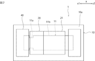
- FIG. 2 is a schematic plan view of the fuse in the first embodiment.
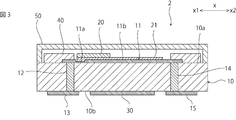
- FIG. 3 is a schematic cross-sectional view of a fuse in the second embodiment.
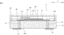
- FIG. 4 is a schematic cross-sectional view of a fuse in the third embodiment.
- FIG. 5 is a schematic plan view of a fuse in the fourth embodiment.
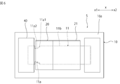
- FIG. 6 is a schematic plan view of a fuse in the fifth embodiment.
- FIG. 1 is a schematic cross-sectional view of a fuse in the first embodiment.
- FIG. 2 is a schematic plan view of the fuse in the first embodiment. In FIG. 2, drawing of the sealing member is omitted.
- the fuse 1 shown in FIGS. 1 and 2 may be a passive element in which the wiring 11 is automatically cut when an overcurrent occurs in the wiring 11 described later, or an active current is detected and detected. Alternatively, an active element that cuts the wiring 11 may be used.
- the fuse 1 includes an insulating substrate 10.
- the insulating substrate 10 can be constituted by, for example, a ceramic substrate such as an alumina substrate, a resin substrate, or the like.
- the insulating substrate 10 may be a multilayer substrate having wiring inside.
- wiring 11 is arranged on the first main surface 10 a of the insulating substrate 10.
- One end of the wiring 11 is connected to a terminal electrode 13 disposed on the second main surface 10 b by a via hole electrode 12.
- the other end of the wiring 11 is connected to a terminal electrode 15 disposed on the second main surface 10b by a via hole electrode 14.
- the wiring 11 is preferably composed mainly of at least one of Ag, Au, and Cu.
- the low melting point metal part 20 is arranged on the wiring 11.
- the low melting point metal portion 20 has a melting point lower than that of the wiring 11 and is made of a low melting point metal that melts the wiring 11 when it becomes a melt.
- Specific examples of such low melting point metals include Sn alloys such as SnSb, SnCu, SnAg, SnAgCu, SnCuNi.
- an insulating layer 21 is disposed between the low melting point metal part 20 and the wiring 11.
- the insulating layer 21 electrically insulates the wiring 11 from the low melting point metal part 20.
- the terminal electrode 13 and the terminal electrode 15 are electrically connected by the via-hole electrodes 12 and 14 and the wiring 11, and no current flows through the low melting point metal part 20. Therefore, the wiring 11 tends to generate heat when an overcurrent occurs. Therefore, the fuse function of the fuse 1 is likely to be activated.
- the insulating layer 21 can electrically insulate the low melting point metal part 20 and the wiring 11 and can be removed by melting in the melt of the low melting point metal part 20 or volatilizing when the melt is generated. It is preferable that The insulating layer 21 can be composed of, for example, rosin flux, organic acid flux, or the like.
- the fuse 1 is provided with a heating element 30 for heating the low melting point metal part 20. Therefore, the fuse 1 can function as a passive element or an active element.
- the heating element 30 can be constituted by, for example, a resistance heating element.
- the heating element 30 is disposed on the second main surface 10 b of the insulating substrate 10.
- the heating element 30 may be electrically connected to the terminal electrode 13 and the terminal electrode 15, for example. In that case, when an overcurrent flows through the wiring 11, the overcurrent also flows through the heating element 30 and the heating element 30 generates heat.
- the wiring 11 and the low melting point metal part 20 are covered with a sealing member 50 disposed on the insulating substrate 10.
- the fuse function of fuse 1 is expressed as follows.
- an overcurrent flows through the fuse 1, the wiring 11 generates heat.
- an overcurrent is detected by a detection mechanism (not shown), current is supplied to the heating element 30 and the heating element 30 generates heat.
- the low melting point metal part 20 is melted and a melt of the low melting point metal part 20 is generated.
- the wiring 11 is cut and the terminal electrode 13 and the terminal electrode 15 are electrically insulated.
- the wiring 11 includes a relatively narrow narrow portion 11a and a relatively wide wide portion 11b.
- the wide portion 11b is connected to the narrow portion 11a on the x2 side of the narrow portion 11a in the x-axis direction, which is the direction in which the wiring 11 extends.
- at least one part of the low melting metal part 20 is provided on the narrow part 11a.
- the melt of the low melting point metal part 20 is generated, the wiring 11 is melted into the melt, so that the narrow part 11a disappears earlier than the wide part 11b, and only the wide part 11b remains. . Then, the melt wets and moves toward the wide portion 11b made of the remaining solid metal. For this reason, the melt is surely isolated from the portion located closer to the x1 side than the narrow portion 11a of the wiring 11. Therefore, the fuse function is surely exhibited and the overcurrent can be reliably interrupted.
- the liquid repellent portion 40 is provided on the insulating substrate 10 on the x1 side opposite to the wide portion 11b of the narrow portion 11a in the x-axis direction.
- the liquid repellent part 40 repels the melt of the low melting point metal part 20. For this reason, the melt of the low melting point metal part 20 is repelled to the x2 side by the liquid repellent part 40 and moves more smoothly to the x2 side.
- the liquid repellent portion 40 is preferably provided across the wiring 11 in the width direction of the wiring 11.
- the liquid repellent part 40 can be comprised by resin materials, such as glass materials, such as a borosilicate type glass, and an epoxy resin, for example. “Repel the melt” means that the contact angle is 90 ° or more.
- the width of the narrow portion 11a is preferably 4/3 times or less the width of the wide portion 11b.
- the width of the narrow portion 11a is not less than 1 ⁇ 2 times the width of the wide portion 11b.
- the low melting point metal portion 20 is disposed over the narrow portion 11a and the wide portion 11b.
- the low melting point metal portion 20 is preferably provided from one side to the other side of the narrow portion 11a in the width direction of the narrow portion 11a.
- the fuse 1 of this embodiment exists as a single element, the fuse of the present invention may be incorporated in an electronic component.
- the fuse of the present invention may be integrated with a wiring board of an electronic component.
- FIG. 3 is a schematic cross-sectional view of a fuse in the second embodiment.
- the narrow part 11a has a thinner part than the wide part 11b.
- the entire narrow part 11a may be thinner than the wide part 11b, or a part of the narrow part 11a may be thinner than the wide part 11b.
- the thickness of the narrow part 11a may be gradually reduced from the end part on the wide part 11b side toward the side opposite to the wide part 11b. In that case, the melt moves smoothly on the wide portion 11b side.
- FIG. 4 is a schematic cross-sectional view of a fuse in the third embodiment.
- the heating element 30 is arranged on the first main surface 10 a of the insulating substrate 10 so that at least a part thereof overlaps the low melting point metal part 20.
- the low melting point metal part 20 and the heating element 30 are insulated by the insulating layer 60. For this reason, the heat of the heating element 30 is likely to be supplied to the low melting point metal part 20.
- the heating element 30 may be provided inside the insulating substrate 10.
- FIG. 5 is a schematic plan view of a fuse in the fourth embodiment.
- FIG. 6 is a schematic plan view of a fuse in the fifth embodiment.
- the narrow portion 11a may have a plurality of portions having different widths.
- the narrow portion 11a is provided so that the width gradually decreases from the wide portion 11b toward the side opposite to the wide portion 11b.
- the width of the narrow portion 11a is configured to be gradually reduced by a straight line, but may be configured to be gradually reduced by a curved line.
- the narrow portion 11a is connected to the wide portion 11b, and the first narrow portion 11a1 and the first narrow portion 11a1 are narrower than the wide portion 11b. And a second narrow portion 11a2 narrower than the first narrow portion 11a1. By doing so, the melt of the low melting point metal part 20 is more easily moved to the wide part 11b side.
Landscapes
- Fuses (AREA)
Description
本発明は、ヒューズに関する。
従来、電子部品に対してヒューズエレメントを接続し、過電流から電子部品を保護する試みがなされている。例えば、特許文献1には、ヒューズエレメントの一例として、配線の溶断部に低融点金属が付着したヒューズエレメントが記載されている。このヒューズエレメントに過電流が流れると、低融点金属が溶融し、低融点金属の融液が形成される。この低融点金属の融液に溶断部が溶解することにより溶断部が溶断される。その結果、過電流が遮断される。
しかしながら、特許文献1に記載のヒューズエレメントでは、過電流を確実に遮断できない場合があるという問題がある。
本発明の目的は、過電流を確実に遮断できるヒューズを提供することにある。
本発明に係るヒューズは、絶縁性基板と、配線と、低融点金属部とを備える。配線は、絶縁性基板の一主面上に配されている。低融点金属部は、配線の上に設けられている。低融点金属部は、配線よりも低い融点を有する。低融点金属部は、融液となった際に配線を溶解させる。配線は、相対的に幅狭な幅狭部と、相対的に幅広な幅広部とを有する。幅広部は、配線の延びる方向における幅狭部の一方側において幅狭部に接続されている。低融点金属部の少なくとも一部は、幅狭部の上に設けられている。
本発明に係るヒューズのある特定の局面では、低融点金属部は、幅狭部の上と幅広部の上とに跨がって配されている。
本発明に係るヒューズの別の特定の局面では、ヒューズは、配線と低融点金属部とを絶縁する絶縁層をさらに備える。
本発明に係るヒューズの他の特定の局面では、ヒューズは、撥液部をさらに備える。撥液部は、絶縁性基板の一主面上において、配線の延びる方向における幅狭部の他方側に設けられている。撥液部は、低融点金属部の融液をはじく。
本発明に係るヒューズのさらに他の特定の局面では、低融点金属部は、幅狭部の幅方向において幅狭部よりも一方側から他方側にわたって設けられている。
本発明に係るヒューズのさらに別の特定の局面では、ヒューズは、低融点金属部を加熱する発熱体をさらに備える。
本発明に係るヒューズのまた他の特定の局面では、発熱体は、基板の一主面上において、少なくとも一部が低融点金属部と重なるように配されている。
本発明に係るヒューズのまた別の特定の局面では、幅狭部は、幅広部よりも薄い部分を有する。
本発明に係るヒューズのさらにまた他の特定の局面では、低融点金属部は、Snを主成分とする。
本発明によれば、過電流を確実に遮断できるヒューズを提供することができる。
以下、本発明を実施した好ましい形態の一例について説明する。但し、下記の実施形態は、単なる例示である。本発明は、下記の実施形態に何ら限定されない。
また、実施形態等において参照する各図面において、実質的に同一の機能を有する部材は同一の符号で参照することとする。また、実施形態等において参照する図面は、模式的に記載されたものである。図面に描画された物体の寸法の比率などは、現実の物体の寸法の比率などとは異なる場合がある。図面相互間においても、物体の寸法比率等が異なる場合がある。具体的な物体の寸法比率等は、以下の説明を参酌して判断されるべきである。
(第1の実施形態)
図1は、第1の実施形態におけるヒューズの略図的断面図である。図2は、第1の実施形態におけるヒューズの略図的平面図である。なお、図2においては、封止部材の描画を省略している。
図1は、第1の実施形態におけるヒューズの略図的断面図である。図2は、第1の実施形態におけるヒューズの略図的平面図である。なお、図2においては、封止部材の描画を省略している。
図1及び図2に示されるヒューズ1は、後述する配線11に過電流が生じた際に配線11が自動的に切断される受動素子であってもよいし、過電流を検知し、能動的に配線11を切断する能動素子であってもよい。
ヒューズ1は、絶縁性基板10を備えている。絶縁性基板10は、例えば、アルミナ基板などのセラミック基板や樹脂基板等により構成することができる。絶縁性基板10は、内部に配線を有する多層基板であってもよい。
絶縁性基板10の第1の主面10aの上には、配線11が配されている。配線11の一方側端部は、ビアホール電極12によって第2の主面10bの上に配された端子電極13に接続されている。配線11の他方側端部は、ビアホール電極14によって第2の主面10bの上に配された端子電極15に接続されている。配線11は、例えば、Ag、Au及びCuの少なくとも一種を主成分とすることが好ましい。
配線11の上には、低融点金属部20が配されている。この低融点金属部20は、配線11よりも低い融点を有すると共に、融液となった際に配線11を融解させる低融点金属からなる。このような低融点金属の具体例としては、例えば,SnSb、SnCu、SnAg,SnAgCu,SnCuNi等のSn合金が挙げられる。
低融点金属部20と配線11との間には、絶縁層21が配されている。この絶縁層21によって配線11と低融点金属部20とが電気的に絶縁されている。このため、通常時においては、端子電極13と端子電極15とは、ビアホール電極12,14と配線11とによって電気的に接続されており、低融点金属部20には電流は流れない。従って、過電流が生じたときに配線11が発熱しやすい。よって、ヒューズ1のヒューズ機能が発動しやすい。
絶縁層21は、低融点金属部20と配線11とを電気的に絶縁できると共に、低融点金属部20の融液に融解したり、融液が生じたときに揮発するなどして除去されたりするものであることが好ましい。絶縁層21は、例えば、ロジン系フラックス、有機酸系フラックス等により構成することができる。
ヒューズ1には、低融点金属部20を加熱する発熱体30が設けられている。このため、ヒューズ1は、受動素子としても機能するし、能動素子として機能させることもできる。発熱体30は、例えば、抵抗発熱体により構成することができる。なお、本実施形態では、発熱体30は、絶縁性基板10の第2の主面10bの上に配されている。発熱体30は、例えば、端子電極13と端子電極15とに電気的に接続されていてもよい。その場合は、配線11に過電流が流れた際に発熱体30にも過電流が流れ発熱体30が発熱する。
配線11、低融点金属部20は、絶縁性基板10の上に配された封止部材50により覆われている。
ヒューズ1のヒューズ機能は以下のようにして発現する。ヒューズ1に過電流が流れた際には、配線11が発熱する。または、図示しない検知機構により過電流が検出され、発熱体30に電流が供給され発熱体30が発熱する。その結果、低融点金属部20が融解され、低融点金属部20の融液が生じる。この低融点金属部20の融液に配線11が融解することにより、配線11が切断され、端子電極13と端子電極15との間が電気的に絶縁される。
ところで、低融点金属部の融液は導電性を有する。このため、低融点金属部の融液が配線の残部同士を接続しているとヒューズ機能は発現しない。ここで、ヒューズ1では、図2に示されるように、配線11は、相対的に幅狭な幅狭部11aと、相対的に幅広な幅広部11bとを含む。幅広部11bは、配線11の伸びる方向であるx軸方向において幅狭部11aのx2側において幅狭部11aに接続されている。そして、低融点金属部20の少なくとも一部は、幅狭部11aの上に設けられている。このため、低融点金属部20の融液が発生すると、配線11が融液に融解することにより、幅狭部11aが幅広部11bよりも早く消失し、幅広部11bのみが残った状態となる。すると、融液は、残存している個体の金属からなる幅広部11bの方にぬれ広がって移動する。このため、融液が配線11の幅狭部11aよりもx1側に位置していた部分から確実に隔離される。従って、ヒューズ機能が確実に発現し、過電流を確実に遮断することができる。
さらに、ヒューズ1では、絶縁性基板10上において、x軸方向における幅狭部11aの幅広部11bとは反対側であるx1側に撥液部40が設けられている。撥液部40は、低融点金属部20の融液をはじく。このため、低融点金属部20の融液は、撥液部40によりx2側にはじかれ、よりスムーズにx2側に移動する。撥液部40は、配線11の幅方向において配線11に跨がって設けられていることが好ましい。撥液部40は、例えば、ホウケイ酸系ガラスなどのガラス材料、エポキシ樹脂などの樹脂材料などにより構成することができる。なお、「融液をはじく」とは、接触角が90°以上であることをいう。
過電流をより確実に遮断する観点からは、幅狭部11aの幅は、幅広部11bの幅の4/3倍以下であることが好ましい。但し、幅狭部11aの幅が狭すぎると、幅狭部11aの電気抵抗率が高くなりすぎる場合がある。従って、幅狭部11aの幅は、幅広部11bの幅の1/2倍以上であることが好ましい。
融液をx2側により移動させやすくする観点からは、低融点金属部20が幅狭部11aの上と幅広部11bの上とに跨がって配されていることが好ましい。
幅狭部11aをより確実に消失させる観点からは、低融点金属部20が幅狭部11aの幅方向において幅狭部11aよりも一方側から他方側にわたって設けられていることが好ましい。
なお、本実施形態のヒューズ1は、単独の素子として存在しているが、本発明のヒューズは、電子部品に組み込まれていてもよい。例えば、本発明のヒューズは、電子部品の配線基板と一体化されていてもよい。
以下、本発明の好ましい実施形態の他の例について説明する。以下の説明において、上記第1の実施形態と実質的に共通の機能を有する部材を共通の符号で参照し、説明を省略する。
(第2の実施形態)
図3は、第2の実施形態におけるヒューズの略図的断面図である。図3に示されるように、ヒューズ2では、幅狭部11aは、幅広部11bよりも薄い部分を有する。このため、幅狭部11aがより消失しやすい。従って、過電流をより確実に遮断することができる。なお、幅狭部11aの全体が幅広部11bよりも薄くてもよいし、幅狭部11aの一部が幅広部11bよりも薄くてもよい。幅狭部11aの厚みは、幅広部11b側の端部から幅広部11bとは反対側に向かって漸減していてもよい。その場合、融液が幅広部11b側によりスムーズに移動する。
図3は、第2の実施形態におけるヒューズの略図的断面図である。図3に示されるように、ヒューズ2では、幅狭部11aは、幅広部11bよりも薄い部分を有する。このため、幅狭部11aがより消失しやすい。従って、過電流をより確実に遮断することができる。なお、幅狭部11aの全体が幅広部11bよりも薄くてもよいし、幅狭部11aの一部が幅広部11bよりも薄くてもよい。幅狭部11aの厚みは、幅広部11b側の端部から幅広部11bとは反対側に向かって漸減していてもよい。その場合、融液が幅広部11b側によりスムーズに移動する。
(第3の実施形態)
図4は、第3の実施形態におけるヒューズの略図的断面図である。図4に示されるように、ヒューズ3では、発熱体30が絶縁性基板10の第1の主面10a上において、少なくとも一部が低融点金属部20と重なるように配されている。低融点金属部20と発熱体30とは、絶縁層60によって絶縁されている。このため、発熱体30の熱が低融点金属部20に供給されやすい。なお、発熱体30は、絶縁性基板10の内部に設けられていてもよい。
図4は、第3の実施形態におけるヒューズの略図的断面図である。図4に示されるように、ヒューズ3では、発熱体30が絶縁性基板10の第1の主面10a上において、少なくとも一部が低融点金属部20と重なるように配されている。低融点金属部20と発熱体30とは、絶縁層60によって絶縁されている。このため、発熱体30の熱が低融点金属部20に供給されやすい。なお、発熱体30は、絶縁性基板10の内部に設けられていてもよい。
(第4及び第5の実施形態)
図5は、第4の実施形態におけるヒューズの略図的平面図である。図6は、第5の実施形態におけるヒューズの略図的平面図である。
図5は、第4の実施形態におけるヒューズの略図的平面図である。図6は、第5の実施形態におけるヒューズの略図的平面図である。
第1の実施形態では、幅狭部11aが略一定の幅で設けられている例について説明した。但し、本発明は、この構成に限定されない。例えば、図5に示されるヒューズ4や図6に示されるヒューズ5のように、幅狭部11aが、幅が異なる複数の部分を有していてもよい。具体的には、ヒューズ4では、幅狭部11aが、幅広部11bから幅広部11bとは反対側に向かって幅が漸減するように設けられている。なお、図5において幅狭部11aの幅は直線により漸減するように構成されているが、曲線により漸減するように構成されていてもよい。また、図6に示されるヒューズ5では、幅狭部11aは、幅広部11bに接続されており、幅広部11bよりも幅狭な第1の幅狭部11a1と、第1の幅狭部11a1に接続されており、第1の幅狭部11a1よりも幅狭な第2の幅狭部11a2とを有する。このようにすることにより低融点金属部20の融液が幅広部11b側により移動しやすくなる。
1~5…ヒューズ
10…絶縁性基板
10a…第1の主面
10b…第2の主面
11…配線
11a…幅狭部
11a1…第1の幅狭部
11a2…第2の幅狭部
11b…幅広部
12,14…ビアホール電極
13,15…端子電極
20…低融点金属部
21…絶縁層
30…発熱体
40…撥液部
50…封止部材
60…絶縁層
10…絶縁性基板
10a…第1の主面
10b…第2の主面
11…配線
11a…幅狭部
11a1…第1の幅狭部
11a2…第2の幅狭部
11b…幅広部
12,14…ビアホール電極
13,15…端子電極
20…低融点金属部
21…絶縁層
30…発熱体
40…撥液部
50…封止部材
60…絶縁層
Claims (9)
- 絶縁性基板と、
前記絶縁性基板の一主面上に配された配線と、
前記配線の上に設けられており、前記配線よりも低い融点を有するとともに、融液となった際に前記配線を溶解させる低融点金属部と、
を備え、
前記配線は、
相対的に幅狭な幅狭部と、
前記配線の延びる方向における前記幅狭部の一方側において前記幅狭部に接続されており、相対的に幅広な幅広部と、
を有し、
前記低融点金属部の少なくとも一部は、前記幅狭部の上に設けられている、ヒューズ。 - 前記低融点金属部は、前記幅狭部の上と前記幅広部の上とに跨がって配されている、請求項1に記載のヒューズ。
- 前記配線と前記低融点金属部とを絶縁する絶縁層をさらに備える、請求項1または2に記載のヒューズ。
- 前記絶縁性基板の一主面上において、前記配線の延びる方向における前記幅狭部の他方側に設けられており、前記低融点金属部の融液をはじく撥液部をさらに備える、請求項1~3のいずれか一項に記載のヒューズ。
- 前記低融点金属部は、前記幅狭部の幅方向において前記幅狭部よりも一方側から他方側にわたって設けられている、請求項1~4のいずれか一項に記載のヒューズ。
- 前記低融点金属部を加熱する発熱体をさらに備える、請求項1~5のいずれか一項に記載のヒューズ。
- 前記発熱体は、前記基板の一主面上において、少なくとも一部が前記低融点金属部と重なるように配されている、請求項6に記載のヒューズ。
- 前記幅狭部は、前記幅広部よりも薄い部分を有する、請求項1~7のいずれか一項に記載のヒューズ。
- 前記低融点金属部は、Snを主成分とする、請求項1~8のいずれか一項に記載のヒューズ。
Applications Claiming Priority (2)
| Application Number | Priority Date | Filing Date | Title |
|---|---|---|---|
| JP2012-188265 | 2012-08-29 | ||
| JP2012188265 | 2012-08-29 |
Publications (1)
| Publication Number | Publication Date |
|---|---|
| WO2014034262A1 true WO2014034262A1 (ja) | 2014-03-06 |
Family
ID=50183085
Family Applications (1)
| Application Number | Title | Priority Date | Filing Date |
|---|---|---|---|
| PCT/JP2013/068339 Ceased WO2014034262A1 (ja) | 2012-08-29 | 2013-07-04 | ヒューズ |
Country Status (2)
| Country | Link |
|---|---|
| TW (1) | TW201411678A (ja) |
| WO (1) | WO2014034262A1 (ja) |
Families Citing this family (1)
| Publication number | Priority date | Publication date | Assignee | Title |
|---|---|---|---|---|
| US12610814B2 (en) * | 2022-10-18 | 2026-04-21 | Nanya Technology Corporation | Electronic fuse device including fuse gate, pass gate, and doping regions |
Citations (3)
| Publication number | Priority date | Publication date | Assignee | Title |
|---|---|---|---|---|
| JPS57113535A (en) * | 1980-11-27 | 1982-07-15 | Bitsukumannbueruke Gmbh | Electric fuse |
| JPH0538748U (ja) * | 1991-10-29 | 1993-05-25 | カルソニツク株式会社 | 自動車用空気調和装置の送風制御装置 |
| JP2000285777A (ja) * | 1999-03-31 | 2000-10-13 | Nec Kansai Ltd | 保護素子 |
-
2013
- 2013-07-04 WO PCT/JP2013/068339 patent/WO2014034262A1/ja not_active Ceased
- 2013-07-26 TW TW102126861A patent/TW201411678A/zh unknown
Patent Citations (3)
| Publication number | Priority date | Publication date | Assignee | Title |
|---|---|---|---|---|
| JPS57113535A (en) * | 1980-11-27 | 1982-07-15 | Bitsukumannbueruke Gmbh | Electric fuse |
| JPH0538748U (ja) * | 1991-10-29 | 1993-05-25 | カルソニツク株式会社 | 自動車用空気調和装置の送風制御装置 |
| JP2000285777A (ja) * | 1999-03-31 | 2000-10-13 | Nec Kansai Ltd | 保護素子 |
Also Published As
| Publication number | Publication date |
|---|---|
| TW201411678A (zh) | 2014-03-16 |
Similar Documents
| Publication | Publication Date | Title |
|---|---|---|
| JP6214318B2 (ja) | 電流ヒューズ | |
| TWI390568B (zh) | Protection element | |
| CN106688073A (zh) | 熔线元件、熔断器件、和发热体内置式熔断器件 | |
| JP5939311B2 (ja) | ヒューズ | |
| WO2017163730A1 (ja) | 保護素子 | |
| JP6389603B2 (ja) | スイッチ素子、スイッチ回路、及び警報回路 | |
| JP2010165685A (ja) | 保護素子及びバッテリーパック | |
| TWI493588B (zh) | fuse | |
| WO2014034261A1 (ja) | ヒューズ | |
| WO2017163766A1 (ja) | 保護素子 | |
| WO2014034262A1 (ja) | ヒューズ | |
| JP6171500B2 (ja) | ヒューズ | |
| JP6102266B2 (ja) | ヒューズ | |
| JP2012059719A (ja) | 保護素子及びバッテリーパック | |
| WO2016098854A1 (ja) | スイッチ素子 | |
| JP6437221B2 (ja) | スイッチ素子、スイッチ回路及び警報回路 | |
| CN105900207A (zh) | 开关元件、开关电路及警报电路 | |
| JP2013178939A (ja) | 電流ヒューズ | |
| JP6142668B2 (ja) | ヒューズ素子 | |
| JP5994410B2 (ja) | 保護素子 | |
| JP2014235940A (ja) | ヒューズ素子 | |
| KR20240105509A (ko) | 회로 모듈 | |
| JP2011023213A (ja) | 回路保護素子 |
Legal Events
| Date | Code | Title | Description |
|---|---|---|---|
| 121 | Ep: the epo has been informed by wipo that ep was designated in this application |
Ref document number: 13833514 Country of ref document: EP Kind code of ref document: A1 |
|
| NENP | Non-entry into the national phase |
Ref country code: DE |
|
| 122 | Ep: pct application non-entry in european phase |
Ref document number: 13833514 Country of ref document: EP Kind code of ref document: A1 |
|
| NENP | Non-entry into the national phase |
Ref country code: JP |