WO2014033887A1 - 移動端末装置、制御方法および制御プログラム - Google Patents
移動端末装置、制御方法および制御プログラム Download PDFInfo
- Publication number
- WO2014033887A1 WO2014033887A1 PCT/JP2012/072082 JP2012072082W WO2014033887A1 WO 2014033887 A1 WO2014033887 A1 WO 2014033887A1 JP 2012072082 W JP2012072082 W JP 2012072082W WO 2014033887 A1 WO2014033887 A1 WO 2014033887A1
- Authority
- WO
- WIPO (PCT)
- Prior art keywords
- access point
- mobile terminal
- display
- communication
- base station
- Prior art date
Links
Images


Classifications
-
- H—ELECTRICITY
- H04—ELECTRIC COMMUNICATION TECHNIQUE
- H04W—WIRELESS COMMUNICATION NETWORKS
- H04W48/00—Access restriction; Network selection; Access point selection
- H04W48/16—Discovering, processing access restriction or access information
-
- H—ELECTRICITY
- H04—ELECTRIC COMMUNICATION TECHNIQUE
- H04W—WIRELESS COMMUNICATION NETWORKS
- H04W52/00—Power management, e.g. TPC [Transmission Power Control], power saving or power classes
- H04W52/02—Power saving arrangements
- H04W52/0203—Power saving arrangements in the radio access network or backbone network of wireless communication networks
- H04W52/0206—Power saving arrangements in the radio access network or backbone network of wireless communication networks in access points, e.g. base stations
-
- H—ELECTRICITY
- H04—ELECTRIC COMMUNICATION TECHNIQUE
- H04W—WIRELESS COMMUNICATION NETWORKS
- H04W52/00—Power management, e.g. TPC [Transmission Power Control], power saving or power classes
- H04W52/02—Power saving arrangements
- H04W52/0209—Power saving arrangements in terminal devices
- H04W52/0261—Power saving arrangements in terminal devices managing power supply demand, e.g. depending on battery level
- H04W52/0267—Power saving arrangements in terminal devices managing power supply demand, e.g. depending on battery level by controlling user interface components
- H04W52/027—Power saving arrangements in terminal devices managing power supply demand, e.g. depending on battery level by controlling user interface components by controlling a display operation or backlight unit
-
- H—ELECTRICITY
- H04—ELECTRIC COMMUNICATION TECHNIQUE
- H04W—WIRELESS COMMUNICATION NETWORKS
- H04W88/00—Devices specially adapted for wireless communication networks, e.g. terminals, base stations or access point devices
- H04W88/02—Terminal devices
- H04W88/06—Terminal devices adapted for operation in multiple networks or having at least two operational modes, e.g. multi-mode terminals
-
- H—ELECTRICITY
- H04—ELECTRIC COMMUNICATION TECHNIQUE
- H04W—WIRELESS COMMUNICATION NETWORKS
- H04W52/00—Power management, e.g. TPC [Transmission Power Control], power saving or power classes
- H04W52/02—Power saving arrangements
- H04W52/0209—Power saving arrangements in terminal devices
- H04W52/0251—Power saving arrangements in terminal devices using monitoring of local events, e.g. events related to user activity
- H04W52/0258—Power saving arrangements in terminal devices using monitoring of local events, e.g. events related to user activity controlling an operation mode according to history or models of usage information, e.g. activity schedule or time of day
-
- Y—GENERAL TAGGING OF NEW TECHNOLOGICAL DEVELOPMENTS; GENERAL TAGGING OF CROSS-SECTIONAL TECHNOLOGIES SPANNING OVER SEVERAL SECTIONS OF THE IPC; TECHNICAL SUBJECTS COVERED BY FORMER USPC CROSS-REFERENCE ART COLLECTIONS [XRACs] AND DIGESTS
- Y02—TECHNOLOGIES OR APPLICATIONS FOR MITIGATION OR ADAPTATION AGAINST CLIMATE CHANGE
- Y02D—CLIMATE CHANGE MITIGATION TECHNOLOGIES IN INFORMATION AND COMMUNICATION TECHNOLOGIES [ICT], I.E. INFORMATION AND COMMUNICATION TECHNOLOGIES AIMING AT THE REDUCTION OF THEIR OWN ENERGY USE
- Y02D30/00—Reducing energy consumption in communication networks
- Y02D30/70—Reducing energy consumption in communication networks in wireless communication networks
Definitions
- the present invention relates to a mobile terminal device, a control method, and a control program.
- a mobile terminal device having a communication function for connecting to a mobile phone network and a communication function for connecting to a wireless LAN (Local Area Network).
- the mobile terminal device can be connected to a network such as the Internet via, for example, a base station of a mobile phone network or a wireless LAN access point installed in various places.
- the position of the terminal is detected based on the electric field strength of the received signal from the base station of the cellular network, and the connection point to the wireless LAN is determined based on the cell ID of the base station and the received signal electric field strength.
- the power consumption of the mobile terminal device is increased by the scanning operation of the mobile terminal device searching for an access point such as a wireless LAN. For example, when a scan operation for searching for an access point of a wireless LAN is started when a handover is performed, the power consumption of the mobile terminal apparatus related to the scan operation for searching for an access point due to frequent handovers Will increase.
- an object of the present invention is to provide a mobile terminal device, a control method, and a control program that can suppress power consumption.
- a first communication unit that connects to a base station, a second communication unit that connects to a network via an access point, and area identification information that identifies a communication area of the base station
- a detection unit included in the mobile terminal device having a storage unit that stores connection history information including a plurality of entries that associate access point identification information that identifies an access point connected to the network in the communication area, Detecting that the screen has transitioned from a non-display state in which a screen is not displayed to a display state in which the screen is displayed, and a determination unit included in the mobile terminal apparatus is configured to include the screen in the communication area of a first base station When the detection unit detects that the display state has been changed from the non-display state, the access included in the communication area of the first base station after a predetermined time has elapsed.
- the second communication unit starts searching for a point, determines whether an entry including the first area identification information of the first base station has been searched from the connection history information, and the mobile terminal apparatus A mobile terminal device, a control method, and a control program for controlling the second communication unit based on a result of the determination by the determination unit after the predetermined time elapses are proposed.
- FIG. 1 is an explanatory diagram of an example of the control method according to the first embodiment.
- FIG. 2 is an explanatory diagram illustrating a system configuration example of the communication system 200.
- FIG. 3 is a block diagram illustrating a hardware configuration example of the mobile terminal device 101.
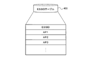
- FIG. 4 is an explanatory diagram showing an example of the stored contents of the ESSID table 400.
- FIG. 5 is an explanatory diagram showing an example of the contents stored in the connection performance table 500.
- FIG. 6 is a block diagram of a functional configuration example of the mobile terminal apparatus 101 according to the first embodiment.
- FIG. 7 is an explanatory diagram (part 1) of an operation example of the mobile terminal device 101 according to the first embodiment.
- FIG. 8 is an explanatory diagram (part 2) of an operation example of the mobile terminal device 101 according to the first embodiment.
- FIG. 9 is an explanatory diagram (part 3) of an operation example of the mobile terminal device 101 according to the first embodiment.
- FIG. 10 is an explanatory diagram (part 4) of an operation example of the mobile terminal device 101 according to the first embodiment.
- FIG. 11 is a flowchart of an example of a first determination processing procedure of the mobile terminal apparatus 101 according to the first embodiment.
- FIG. 12 is a flowchart of an example of a second determination processing procedure of the mobile terminal apparatus 101 according to the first embodiment.
- FIG. 13 is a flowchart illustrating an example of a specific process procedure of the table update process.
- FIG. 14 is a flowchart of an example of a first communication control process procedure of the mobile terminal apparatus 101 according to the first embodiment.
- FIG. 15 is a flowchart of an example of a second communication control process procedure of the mobile terminal apparatus 101 according to the first embodiment.
- FIG. 16 is a flowchart of an example of a third determination processing procedure of the mobile terminal apparatus 101 according to the first embodiment.
- FIG. 17 is a flowchart of an example of a third communication control process procedure of the mobile terminal apparatus 101 according to the first embodiment.
- FIG. 18 is an explanatory diagram showing an example of scanning operation of the access point APj.
- FIG. 19 is an explanatory diagram of an operation example of the mobile terminal apparatus 101 according to the second embodiment.
- FIG. 20 is a flowchart of an example of a determination process procedure of the mobile terminal apparatus 101 according to the second embodiment.
- FIG. 21 is a flowchart of an example of a communication control processing procedure of the mobile terminal apparatus 101 according to the second embodiment.
- FIG. 22 is an explanatory diagram (part 1) of an operation example of the mobile terminal device 101 according to the third embodiment.
- FIG. 23 is an explanatory diagram (part 2) of an operation example of the mobile terminal device 101 according to the third embodiment.
- FIG. 24 is an explanatory diagram (part 3) of an operation example of the mobile terminal apparatus 101 according to the third embodiment.
- FIG. 25 is a flowchart of an example of a determination processing procedure of the mobile terminal apparatus 101 according to the third embodiment.
- FIG. 26 is a flowchart of an example of a communication control process procedure of the mobile terminal apparatus 101 according to the third embodiment.
- FIG. 27 is a flowchart of an example of an update process procedure of the mobile terminal apparatus 101 according to the third embodiment.
- FIG. 1 is an explanatory diagram of an example of the control method according to the first embodiment.
- a mobile terminal device 101 is a computer that has a screen 110 that displays various types of information and can wirelessly communicate with a base station 102 and an access point 103.
- the mobile terminal device 101 is a smartphone, a mobile phone, a tablet PC (Personal Computer), a PHS (Personal Handy-phone System), or the like.
- the base station 102 and the access point 103 are capable of wireless communication with the mobile terminal device 101 existing in each communication area.
- the base station 102 and the access point 103 are wireless stations that serve as bases for connecting the mobile terminal device 101 to the network.
- the base station 102 is a base station of a mobile communication network (mobile phone network) scattered in various places.
- the access points 103 are, for example, wireless LAN access points scattered in various places.
- the mobile terminal apparatus 101 can detect the base station 102 and the access point 103 by different detection operations, and can connect to the network via the detected base station 102 and access point 103.
- Examples of the network include a mobile communication network, a LAN, a WAN (Wide Area Network), and the Internet.
- the detection operation is a so-called scanning operation for searching for a communicable base station 102 or access point 103 among the base stations 102 and access points 103 scattered in various places.
- the detection operation for detecting the base station 102 and the access point 103 differs depending on, for example, differences in wireless communication methods, communication standards, communication performance, communication services, and the like.
- the mobile terminal apparatus 101 performs another detection operation different from the detection operation for detecting the base station 102 in order to detect the access point 103. For this reason, the mobile terminal apparatus 101 consumes power by the detection operation for detecting the base station 102 and consumes power by the detection operation for detecting the access point 103.
- a base station of a mobile communication network is taken as an example, and as an example of the access point 103, a wireless LAN access point is taken as an example.
- the communication area of the base station 102 may be referred to as “cell C”.
- base stations 102-1 to 102-3 are shown as base stations 102 of the mobile communication network, and access points 103-1 to 103-12 are shown as access points 103 of the wireless LAN. Yes. Further, cells C1 to C3 of the base stations 102-1 to 102-3 and communication areas A1 to A12 of the access points 103-1 to 103-12 are shown.
- the access point 103 of the wireless LAN tends to have a narrow communication area while the maximum communication speed is high and the transmission efficiency is high compared to the base station 102 of the mobile communication network.
- the wireless LAN access point 103 can be used only by users who subscribe to a specific service.
- the mobile terminal device 101 When there is no access point 103 that can be used around the mobile terminal device 101, it is not desirable for the mobile terminal device 101 to perform an access point 103 detection operation. Further, when using the access point 103, it is conceivable that the user instructs the start of the detection operation of the access point 103. However, the user's operation input is required and the installation position of the available access point 103 is determined. The user may not know.
- the mobile terminal apparatus 101 starts the scanning operation of the access point 103 of the wireless LAN when the screen 110 transitions from the non-display state to the display state. Further, when the mobile terminal apparatus 101 is not connected to the access point 103 after the elapse of the predetermined time T, the mobile terminal apparatus 101 determines whether there is a connection history to the access point 103 in the cell C to which the mobile terminal apparatus 101 belongs. Then, the mobile terminal device 101 continues the scanning operation when there is a connection history to the access point 103, and stops the scanning operation when there is no connection history to the access point 103.
- the mobile terminal device 101 prevents the usability from being impaired and suppresses the power consumption required for the scanning operation of the access point 103.
- the detection operation for detecting the base station 102 of the mobile communication network is assumed to be periodically performed by the mobile terminal device 101, for example.
- an example of the communication control process of the mobile terminal apparatus 101 according to the first embodiment will be described.
- the mobile terminal apparatus 101 detects a transition from a non-display state where the screen 110 is not displayed to a display state where the screen 110 is displayed.
- the non-display state (screen OFF) is, for example, a state where power supply to the screen 110 is stopped.
- the display state (screen ON) is a state in which power is supplied to the screen 110, for example.
- the non-display state where the screen 110 is not displayed is referred to as “the display state of the screen 110 is not displayed”
- the display state where the screen 110 is displayed is referred to as “the display state of the screen 110 is displayed”.
- the mobile terminal apparatus 101 scans the access point 103 included in the cell C of the base station 102. Start operation.
- the mobile terminal apparatus 101 searches the connection information 120 for an entry including access point identification information for identifying the searched access point 103. Then, the mobile terminal apparatus 101 determines whether an entry including access point identification information for identifying the searched access point 103 is searched from the connection information 120.
- connection information 120 is information specifying access point identification information of the access point 103 connected to a network such as the Internet, that is, the available access point 103.
- the access point identification information is, for example, an ESSID (Extended Service Set Identifier) of the access point 103, a BSSID (Basic Service Set Identifier), or the like.
- the same access point identification information may be assigned to a plurality of access points 103.
- the access point 103 to which the same access point identification information is given for example, available communication services are installed in a set of the same access points or each of a plurality of stores operated by a certain company. There is a collection of access points. For this reason, even if the user of the mobile terminal apparatus 101 has never used the searched access point 103, access point identification information for identifying the searched access point 103 is searched from the connection information 120. There is.
- connection operation to the access point 103 is a connection process for connecting to a network such as the Internet via the access point 103.
- the mobile terminal device 101 can be connected to a network such as the Internet via the access point 103.
- the access point 103 is not searched for or the entry is not searched for from the connection information 120, the mobile terminal apparatus 101 repeats the scanning operation of the access point 103.
- connection history information 130 includes area identification information for identifying the cell C of the base station 102 and access point identification information for identifying the access point 103 connected to a network such as the Internet in the cell C of the base station 102. And an entry associated with each other.
- connection history information 130 is information for identifying the cell C in which the connection operation to the access point 103 is performed among the cell group (for example, the cells C1 to C3) of the base station 102.
- the connection operation to the access point 103 is an operation to connect to the network via the access point 103.
- connection history to the access point 103 is a history that the connection processing of the mobile terminal device 101 to the access point 103 has been normally completed.
- a user authentication process of the mobile terminal apparatus 101 is performed. That is, the cell C having a connection history to the access point 103 is more likely to have an access point 103 that can be used by the user of the mobile terminal device 101 than the cell C having no connection history to the access point 103. Cell C.
- the predetermined time T is set to a time at which the scanning operation of the access point 103 can be performed a plurality of times, for example.
- the predetermined time T may be an elapsed time after the display state of the screen 110 transitions from non-display to display, or may be an elapsed time after the scanning operation of the access point 103 is started. .
- the mobile terminal apparatus 101 when the mobile terminal apparatus 101 is disconnected from the access point 103 after a predetermined time T has elapsed since the display state of the screen 110 has changed to display, the area of the base station 102 to which the mobile terminal apparatus 101 belongs An entry including identification information may be searched from the connection history information 130. Then, the mobile terminal apparatus 101 determines whether an entry including the area identification information of the base station 102 to which the mobile terminal apparatus belongs is searched from the connection history information 130.
- the communication area of the access point 103 indicated by a bold circle represents the communication area of the access point 103 with the connection history of the mobile terminal device 101.
- the communication area of the access point 103 represented by a dotted circle represents the communication area of the access point 103 to which the same access point identification information as that of the access point 103 with the connection history of the mobile terminal device 101 is assigned. ing.
- the mobile terminal apparatus 101 scans the access point 103 based on the determination result of determining whether the entry including the area identification information of the base station 102 has been searched from the connection history information 130 after the predetermined time T has elapsed. To control.
- the mobile terminal apparatus 101 accesses the access included in the cell C of the base station 102.
- the search for point 103 is continued. That is, if the mobile terminal apparatus 101 belongs to the cell C having a connection history to the access point 103 after the elapse of the predetermined time T, the mobile terminal apparatus 101 continuously performs the scanning operation of the access point 103.
- the mobile terminal apparatus 101 searches for the access point 103 included in the cell of the base station 102. Stop. That is, if the mobile terminal apparatus 101 belongs to the cell C having no connection history to the access point 103 after the predetermined time T has elapsed, the mobile terminal apparatus 101 stops the scanning operation of the access point 103.
- control processing examples 1, 2, and 3 of the mobile terminal device 101 will be described by taking the case where the display state of the screen 110 transitions from non-display to display at the points a, b, c, and d shown in FIG. , 4 will be described.
- ⁇ Control processing example 1> First, a case is assumed where the display state of the screen 110 transitions from non-display to display at a point a where the user of the mobile terminal device 101 is located. In this case, the mobile terminal apparatus 101 starts a scanning operation for the access point 103 included in the cell C1 of the base station 102-1. As a result, it is assumed that the access point 103-1 has been searched before the predetermined time T has elapsed since the display state of the screen 110 transitioned from non-display to display.
- the access point 103-1 is an access point 103 connected to a network such as the Internet. For this reason, the mobile terminal apparatus 101 determines that an entry including access point identification information for identifying the access point 103-1 has been retrieved from the connection information 120.
- the mobile terminal device 101 performs a connection operation to the access point 103-1.
- the mobile terminal device 101 can be connected to a network such as the Internet via the access point 103-1.
- the access point 103-5 is an access point 103 that has never been connected from the mobile terminal device 101 to a network such as the Internet. For this reason, the mobile terminal apparatus 101 determines that the entry including the access point identification information for identifying the access point 103-5 has not been retrieved from the connection information 120.
- the mobile terminal apparatus 101 does not perform the connection operation to the access point 103-5.
- the mobile terminal device 101 has an entry including the area identification information of the base station 102 to which the mobile device 101 belongs, after a predetermined time T has elapsed since the display state of the screen 110 transitioned from non-display to display. It is determined whether the information 130 is retrieved.
- the mobile terminal apparatus 101 determines that an entry including the area identification information of the base station 102-2 to which the mobile terminal apparatus 101 belongs has not been retrieved from the connection history information 130. In this case, the mobile terminal apparatus 101 stops the scanning operation of the access point 103.
- the access point 103-7 is an access point 103 that is installed in the store A and has never been connected from the mobile terminal device 101 to a network such as the Internet.
- the same access point identification information for example, ESSID
- ESSID access point identification information
- the access point 103-8 installed in the store B is the access point 103 connected to a network such as the Internet. That is, the access point 103-7 is the access point 103 to which the same access point identification information (for example, ESSID) is given as the access point 103-8 connected to a network such as the Internet.
- the same access point identification information for example, ESSID
- the mobile terminal apparatus 101 determines that an entry including access point identification information for identifying the access point 103-7 has been retrieved from the connection information 120.
- the mobile terminal apparatus 101 performs a connection operation to the access point 103-7.
- the mobile terminal apparatus 101 can be connected to a network such as the Internet via the access point 103-7.
- the access point 103-12 is an access point 103 that has never been connected to a network such as the Internet from the mobile terminal apparatus 101. For this reason, the mobile terminal apparatus 101 determines that the entry including the access point identification information for identifying the access point 103-12 has not been retrieved from the connection information 120.
- the mobile terminal apparatus 101 does not perform the connection operation to the access point 103-12.
- the mobile terminal device 101 has an entry including the area identification information of the base station 102 to which the mobile device 101 belongs, after a predetermined time T has elapsed since the display state of the screen 110 transitioned from non-display to display. It is determined whether the information 130 is retrieved.
- an access point 103-8 having a connection history in the cell C3 of the base station 102-3 is shown. For this reason, the mobile terminal apparatus 101 determines that an entry including the area identification information of the base station 102-3 to which the mobile terminal apparatus 101 belongs is retrieved from the connection history information 130. In this case, the mobile terminal apparatus 101 continuously performs the scanning operation of the access point 103.
- the scanning operation of the access point 103 included in the cell C of the base station 102 can be started.
- an available access point 103 existing around the mobile terminal device 101 can be searched and connected to a network such as the Internet, and usability can be ensured.
- the scan operation is continued if the access point 103 is more likely to exist than the cell C that has no connection history to the access point 103. Can be done. As a result, reconnectability to the access point 103 can be improved and usability can be prevented from being impaired. Note that the reconnectability to the access point 103 represents, for example, the short time required to connect to the available access point 103.
- the scanning operation of the access point 103 can be stopped.
- the scan operation is performed when the access point 103 that is less likely to exist than the cell C that has a connection history to the access point 103 belongs to the cell C.
- power consumption for the scan operation of the access point 103 is prevented while preventing the usability from being impaired. Can be suppressed.
- the mobile terminal apparatus 101 may not be able to search for the access point 103 by a single scan operation.
- the scanning operation of the access point 103 can be performed a plurality of times before the predetermined time T has elapsed since the screen was turned on. That is, according to the mobile terminal device 101, it is possible to secure a time during which the scanning operation can be performed a plurality of times before the scanning operation of the access point 103 started when the screen is turned on, and reconnectability to the access point 103 is achieved. Can be increased.
- FIG. 2 is an explanatory diagram showing a system configuration example of the communication system 200.
- a communication system 200 includes a mobile terminal device 101, base stations BS1 to BSn, access points AP1 to APm, and a server 201.
- base stations BS1 to BSn, access points AP1 to APm, and a server 201 are connected via a network 210.
- the network 210 includes, for example, a mobile communication network, LAN, WAN, and the Internet.
- the base stations BS1 to BSn are mobile communication network base stations scattered in various places.
- base station BSi an arbitrary base station among the base stations BS1 to BSn
- cell Ci a communication area indicating a communicable range of the base station BSi
- the base station 102 shown in FIG. 1 corresponds to the base station BSi.
- the access points AP1 to APm are wireless LAN base stations scattered in various places.
- the access points AP1 to APm may include a portable access point or an access point installed on a moving body such as a train or a bus.
- an arbitrary access point among the access points AP1 to APm may be referred to as “access point APj”, and a communication area indicating a communicable range of the access point APj may be referred to as “communication area Aj”.
- J 1, 2,..., M).
- the access point 103 shown in FIG. 1 corresponds to the access point APj.
- the mobile terminal apparatus 101 can wirelessly communicate with the base station BSi in the cell Ci, and can be connected to the network 210 via the base station BSi.
- the mobile terminal apparatus 101 can wirelessly communicate with the access point APj in the communication area Aj, and can be connected to the network 210 via the access point APj.
- the server 201 is a computer that provides a service to the mobile terminal device 101 via the network 210.
- the service is information processing provided to the mobile terminal apparatus 101, and examples thereof include a mail service, a telephone service, and a web service.
- the server 201 includes a mail server, a web server, an application server, a database server, and the like.
- the mobile terminal device 101 may be provided for each user who uses the communication system 200, and the server 201 may be provided for each service provider.
- FIG. 3 is a block diagram illustrating a hardware configuration example of the mobile terminal device 101.
- a mobile terminal device 101 includes a CPU 301, a memory 302, a display 303, a keypad 304, a public network I / F (Interface) 305, a WLAN (Wireless LAN) I / F 306, and audio signal processing.
- the CPU 301 governs overall control of the mobile terminal device 101.
- the memory 302 includes, for example, a ROM (Read Only Memory), a RAM (Random Access Memory), a flash ROM, and the like.
- the flash ROM stores an OS (Operating System) program
- the ROM stores an application program
- the RAM is used as a work area of the CPU 301.
- the program stored in the memory 302 is loaded into the CPU 301, thereby causing the CPU 301 to execute the coded process.
- the display 303 displays data such as a document, an image, and function information as well as a cursor, an icon, or a tool box.
- a liquid crystal display, an organic EL (Electroluminescence) display, or the like can be adopted as the display 303.
- the screen 110 illustrated in FIG. 1 corresponds to the display 303.
- the keypad 304 includes keys for inputting letters, numbers, various instructions, etc., and inputs data.
- the keypad 304 may be, for example, a touch panel type input pad, a numeric keypad, or a power key.
- the public network I / F 305 is connected to the network 210 via the base station BSi of the mobile communication network, and is connected to another computer (for example, the server 201) via the network 210.
- the public network I / F 305 controls an internal interface with the network 210 and controls input / output of data from other computers.
- the WLAN I / F 306 is connected to the network 210 via a wireless LAN access point APj and is connected to another computer via the network 210.
- the WLAN I / F 306 controls an internal interface with the network 210 and controls input / output of data from other computers.
- the audio signal processing unit 307 is connected to the speaker 308 and the microphone 309. For example, sound received by the microphone 309 is A / D converted by the sound signal processing unit 307. In addition, sound is output from the speaker 308.
- the mobile terminal apparatus 101 includes, for example, a memory controller that controls reading / writing of data with respect to the memory 302 and a PMU (Power Management) that supplies a power supply voltage to each component. Unit), battery, various timers, GPS (Global Positioning System) unit, and the like.
- the hardware configurations of the base station BSi and the access point APj are realized by, for example, a CPU, a memory, an I / F, an auxiliary storage device, a bus, and the like.
- the ESSID table 400 is realized by, for example, the memory 302 illustrated in FIG.
- the connection information 120 illustrated in FIG. 1 corresponds to the ESSID table 400.
- FIG. 4 is an explanatory diagram showing an example of the contents stored in the ESSID table 400.
- the ESSID table 400 stores the ESSID of the access point APj connected to the network 210 from the mobile terminal device 101.
- the mobile terminal apparatus 101 can specify the ESSID (for example, AP1, AP2, AP3) of the access point APj that can be used by the user of the mobile terminal apparatus 101 by referring to the ESSID table 400.
- the ESSID for example, AP1, AP2, AP3
- the storage content of the ESSID table 400 is updated, for example, at the first connection to the access point APj. Specifically, for example, the ESSID of the connected access point APj is newly registered in the ESSID table 400 at the first connection to the access point APj by a user operation input.
- connection performance table 500 used by the mobile terminal device 101
- the connection result table 500 is realized by, for example, the memory 302 illustrated in FIG.
- the connection history information 130 illustrated in FIG. 1 corresponds to the connection performance table 500.
- FIG. 5 is an explanatory diagram showing an example of the stored contents of the connection performance table 500.
- the connection performance table 500 has fields for Cell-ID, ESSID, and last connection time.
- connection record information (for example, connection record information 500-1 to 500-3) is stored as a record.
- Cell-ID is area identification information for identifying the cell Ci of the base station BSi of the mobile communication network.
- the ESSID is access point identification information for identifying the wireless LAN access point APj.
- the last connection time indicates the date and time when the last connection to the access point APj.
- connection record information 500-1 when the connection record information 500-1 is taken as an example, Cell-ID “C1”, ESSID “AP1”, and last connection time “2011.03.2.09.00” are shown in association with each other. .
- the connection result information 500-1 the date and time “March 2, 2011, 9:00:00” when the communication apparatus 101 was last connected to the access point AP1 in the cell C1 of the base station BS1 can be specified.
- the present invention is not limited to this.
- the BSSID of the access point APj may be used as the access point identification information, or both the ESSID and BSSID of the access point APj may be used.
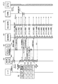
- FIG. 6 is a block diagram of a functional configuration example of the mobile terminal apparatus 101 according to the first embodiment.
- the mobile terminal apparatus 101 includes a first communication unit 601, a second communication unit 602, a detection unit 603, an acquisition unit 604, a determination unit 605, a communication control unit 606, and an update unit 607. It is the structure containing these.
- the first communication unit 601 to the update unit 607 are functions as control units. Specifically, for example, by causing the CPU 301 to execute a program stored in the memory 302 shown in FIG. 3, or a public network
- the functions are realized by hardware such as the I / F 305 and the WLAN I / F 306.
- the processing result of each functional unit is stored in the memory 302, for example.
- the first communication unit 601 has a function of communicating with the base station BSi. Specifically, for example, the first communication unit 601 periodically transmits base station information including the Cell-ID of the cell Ci from the communicable base station BSi among the base stations BS1 to BSn (for example, 2.56 [ Every second]. For example, when the Cell-ID included in the received base station information is different from the Cell-ID included in the previously received base station information, the mobile terminal apparatus 101 communicates with the base station BSi to Perform location registration.
- the second communication unit 602 has a function of communicating with the access point APj. Specifically, for example, the second communication unit 602 connects to the network 210 via the access point APj.
- the detection unit 603 has a function of detecting that the display state of the display 303 (see FIG. 3) has changed from non-display to display. Specifically, for example, when the detection unit 603 switches the display state of the display 303 from non-display to display by a user operation input using the keypad 304, the display state of the display 303 is changed from non-display. Detects transition to display.
- the detection unit 603 when the detection unit 603 resumes the work from the state immediately before the display state of the display 303 is hidden by the resume function, the display state of the display 303 transitions from non-display to display. This may be detected. Further, for example, when an application such as an alarm that is activated at a predetermined time is activated, the detection unit 603 may detect that the display state of the display 303 has changed from non-display to display. .
- the detection unit 603 has a function of detecting that the display state of the display 303 has changed from display to non-display. Specifically, for example, when the display unit 303 switches the display state of the display 303 from display to non-display by a user operation input using the keypad 304, the display state of the display 303 is not displayed. Detects transition to display.
- the detection unit 603 may detect that the display state of the display 303 has changed from display to non-display when the screen OFF timer reaches a specified value.
- the screen OFF timer is a timer that measures the time until the display state of the display 303 transitions from display to non-display. Further, for example, when the detection unit 603 suppresses power supply to the display 303 and shifts to the power saving mode, the detection state of the display 303 may be detected to change from display to non-display.
- the acquisition unit 604 has a function of acquiring a Cell-ID for identifying the cell Ci to which the own device belongs among the cells C1 to Cn of the base stations BS1 to BSn. Specifically, for example, the acquisition unit 604 uses the Cell-ID included in the base station information received by the first communication unit 601 communicating with the base station BSi as the Cell-ID of the cell Ci to which the device belongs. get.
- the acquisition unit 604 uses the Cell-ID included in the base station information of the base station having the maximum radio wave intensity among a plurality of communicable base stations to identify the cell Ci to which the device belongs. You may decide to acquire as ID.
- the determination unit 605 has a function of determining whether or not there is a connection record to the access point APj in the cell Ci to which the own device belongs.
- the connection result to the access point APj is a connection history indicating that the connection operation to the access point APj is completed.
- the connection operation to the access point APj is an operation of the mobile terminal device 101 that connects to the network 210 via the access point APj.
- the determination unit 605 determines whether or not a predetermined time T has elapsed since the detection unit 603 detected that the display state transitioned from non-display to display. Then, when the predetermined time T has elapsed, the determination unit 605 refers to the connection performance table 500 illustrated in FIG. 5 and stores the access point APj stored in association with the Cell-ID acquired by the acquisition unit 604. It is determined whether there is an ESSID.
- the determination unit 605 determines that there is a connection record to the access point APj in the cell Ci to which the own device belongs.
- the determination unit 605 determines that there is no connection record to the access point APj in the cell Ci to which the own device belongs.
- the mobile terminal apparatus 101 can use the access by receiving the probe response signal including the ESSID as a result of transmitting the probe request signal to each CH (channel) used for the wireless LAN. Search for the point APj.
- a probe response signal from another access point may be received immediately before receiving a probe response signal from an available access point APj.
- probe response signals from other access points since probe response signals from other access points are being processed, probe response signals from available access points APj may not be received.
- the predetermined time T is set to a time (for example, 2 [minutes]) that allows the scanning operation of the access point APj to be performed a plurality of times.
- the predetermined time T is stored in the memory 302, for example.
- the elapsed time after it was detected that the display state transitioned from non-display to display can be measured by a timer, for example.
- a timer that measures an elapsed time after it is detected that the display state of the display 303 has changed from non-display to display may be referred to as a “scan timer”.
- the communication control unit 606 has a function of controlling the scanning operation of the access point APj.
- the communication control unit 606 controls the second communication unit 602 and transmits a probe request signal to each CH (channel) used in the wireless LAN.
- the communication control unit 606 can detect a communicable access point APj by receiving the probe response signal including the ESSID.
- the communication control unit 606 controls the second communication unit 602 to detect the access point APj. Start operation. More specifically, when the communication control unit 606 sets the scan operation flag to ON, the second communication unit 602 starts a periodic scan operation of the access point APj.
- the scan operation flag is a flag indicating whether or not the scan operation of the access point APj is periodically performed.
- the scan operation flag is stored in, for example, a memory 302 or a register of the CPU 301. Thereby, while the scan operation flag is set to ON, the scan operation of the access point APj can be performed periodically.
- the scan operation cycle of the access point APj can be arbitrarily set. Further, the start timing when the scanning operation of the access point APj is periodically performed is controlled by, for example, a timer.
- the communication control unit 606 controls the scanning operation of the access point APj based on the determination result determined by the determination unit 605. Specifically, for example, the communication control unit 606 controls the second communication unit 602 when it is determined that there is a connection record to the access point APj in the cell Ci to which the own device belongs after the elapse of the predetermined time T. Then, the scanning operation of the access point APj is continued.
- the communication control unit 606 controls the second communication unit 602 to control the access point APj. Stop the scan operation. More specifically, when the communication control unit 606 sets the scan operation flag to OFF, the periodic scan operation of the access point APj of the second communication unit 602 can be stopped.
- the communication control unit 606 has a function of controlling the second communication unit 602 and starting a connection operation to the access point APj. Specifically, for example, first, the communication control unit 606 refers to the ESSID table 400 illustrated in FIG. 4 and determines whether or not the ESSID of the access point APj searched by the scanning operation is registered.
- the communication control unit 606 controls the second communication unit 602 to start a connection operation to the access point APj.
- the communication control unit 606 does not start the connection operation to the access point APj.
- the communication control unit 606 may start the connection operation to the access point APj searched by the scanning operation by controlling the second communication unit 602 by the user's operation input. Specifically, for example, when connecting to the access point APj for the first time, the communication control unit 606 controls the second communication unit 602 by a user operation input and starts a connection operation to the access point APj. In this case, the communication control unit 606 may newly register the ESSID of the connected access point APj in the ESSID table 400.
- the communication control unit 606 controls the second communication unit 602 to perform the scan operation of the access point APj. You may decide to stop. Thereby, the scanning operation of the access point APj when the display state of the display 303 is not displayed can be suppressed, and the power consumption of the mobile terminal apparatus 101 can be suppressed.
- the communication control unit 606 detects that the display state of the display 303 has changed from display to non-display, and when the predetermined time t has elapsed since the display state has changed to non-display.
- the communication unit 602 may be controlled to stop the scanning operation of the access point APj. As a result, it is possible to keep the scan operation flag ON, assuming that the display state transitions from non-display to display immediately after the display state of the display 303 transitions from display to non-display.
- the update unit 607 has a function of updating the connection time to the access point APj when the connection to the access point APj is completed.
- the connection time represents, for example, the last time of connection to the access point APj.
- the update unit 607 obtains connection record information corresponding to the combination of the Cell-ID of the cell Ci to which the own device belongs and the ESSID of the access point APj that has been connected from the connection record table 500. Search for. Then, the update unit 607 overwrites the connection time to the access point APj in the last connection time field of the searched connection result information.
- the update unit 607 may search the connection record table 500 for connection record information corresponding to the Cell-ID of the cell Ci to which the own device belongs. In this case, the update unit 607 overwrites the ESSID field of the detected access point APj in the ESSID field of the searched connection record information. Also, the update unit 607 overwrites the detected connection time to the access point APj in the final connection time field of the retrieved connection result information.
- connection record information corresponding to the Cell-ID of the cell Ci to which the own apparatus belongs is not retrieved.
- the update unit 607 sets the Cell-ID of the cell Ci to which the own device belongs, the ESSID of the detected access point APj, and the connection time in each field in the connection record table 500. As a result, new connection record information is newly registered in the connection record table 500 as a record.
- the update unit 607 may calculate the total number M of connection record information stored in the connection record table 500. And the update part 607 may delete the connection performance information with the oldest last connection time among the connection performance information memorize
- the threshold value M max represents an upper limit value of connection record information that can be registered in the connection record table 500.
- the threshold value M max can be arbitrarily set.
- the threshold value M max is preset and stored in the memory 302.
- the detection unit 603 may detect that the lock state is released after the display state of the display 303 transitions from non-display to display.
- the locked state is a state in which user operation input is restricted. For example, when the mobile terminal device 101 is in a locked state, the mobile terminal device 101 is in a state that does not accept any operation input other than the unlocking operation. Specifically, for example, the detection unit 603 detects that the lock state of the display 303 is released when a user operation input for releasing the lock state is performed using the keypad 304.
- the communication control unit 606 controls the second communication unit 602 when the detection unit 603 detects that the display state transitions from non-display to display and the lock state is released.
- the operation of detecting the access point APj may be started. This suppresses the scanning operation of the access point APj when the display state of the display 303 is changed from non-display to display or when an unauthorized user tries to use the mobile terminal apparatus 101 to reduce power consumption. Can be suppressed.
- FIG. 7 is an explanatory diagram (part 1) of an operation example of the mobile terminal device 101 according to the first embodiment.
- the operation example of the mobile terminal apparatus 101 shown in FIG. 7 is an operation example when there is no connection record to the access point APj in the cell Ci to which the own apparatus belongs.
- the detection unit 603 detects that the display state of the display 303 has changed from non-display to display. In the example of FIG. 7, it is detected that the display state of the display 303 has changed from non-display to display as a result of the display state of the display 303 being switched from non-display to display by a user operation input.
- the detection unit 603 When detecting that the display state of the display 303 has changed from non-display to display, the detection unit 603 notifies the communication control unit 606 of a screen ON notification and starts a scan timer.
- the screen ON notification is a notification indicating that the display state of the display 303 has changed from non-display to display.
- the communication control unit 606 controls the second communication unit 602 to start the access point APj detection operation. Specifically, for example, when the communication control unit 606 sets the scan operation flag to ON, the second communication unit 602 starts a periodic scan operation of the access point APj.
- the communication control unit 606 reads the ESSID table 400 and determines whether or not the ESSID included in the scan result from the second communication unit 602 is registered in the ESSID table 400.
- the scan result is information including the ESSID of the access point APj searched by the scan operation.
- the communication control unit 606 controls the second communication unit 602 to start a connection operation to the access point APj.
- the communication control unit 606 does not start the connection operation to the access point APj.
- the connection operation to the access point APj is not started.
- the determination unit 605 requests the acquisition unit 604 to acquire the Cell-ID of the cell Ci to which the own device belongs after the elapse of a predetermined time T from the start of the scan timer. Get the Cell-ID of the cell Ci to which. In the example of FIG. 7, the Cell-ID “C3” of the cell C3 to which the own device belongs is acquired.
- the determination unit 605 requests the communication control unit 606 to acquire the ESSID of the connected access point APj, thereby acquiring the ESSID of the connected access point APj.
- “no ESSID” indicating that the access point APj is not connected is notified from the communication control unit 606 to the determination unit 605.
- the determination unit 605 reads the connection result table 500 and determines whether or not there is a connection result to the access point APj in the cell Ci to which the own device belongs. In the example of FIG. 7, since the connection record information corresponding to the acquired Cell-ID “C3” is not registered, it is determined that there is no connection record to the access point APj.
- the determination unit 605 transmits a scan operation flag OFF setting request to the communication control unit 606.
- the OFF setting request is a request to turn off the scan operation flag.
- the mobile terminal apparatus 101 it is possible to start a scan operation of the access point APj periodically when the screen is turned on. If the access point APj is not connected even after a predetermined time T has elapsed since the screen was turned on, the periodic scanning operation of the access point APj can be stopped.
- the determination unit 605 may read the scan operation flag and transmit a scan operation flag OFF setting request to the communication control unit 606 when the scan operation flag is ON. Good. Thereby, the notification of the OFF setting request when the scanning operation flag is OFF can be stopped, and the processing load on the mobile terminal apparatus 101 can be reduced.
- FIG. 8 is an explanatory diagram (part 2) of an operation example of the mobile terminal device 101 according to the first embodiment.
- the operation example of the mobile terminal apparatus 101 shown in FIG. 8 is an operation example when there is a connection record to the access point APj in the cell Ci to which the own apparatus belongs.
- the determination unit 605 reads the connection result table 500 and determines whether or not there is a connection result to the access point APj in the cell Ci to which the own device belongs. In the example of FIG. 8, since the connection record information corresponding to the acquired Cell-ID “C1” has already been registered, it is determined that there is a connection record to the access point APj.
- the determination unit 605 transmits a scan operation flag ON setting request to the communication control unit 606.
- the ON setting request is a request to turn on the scan operation flag.
- the communication control unit 606 returns Ack to the determination unit 605 when receiving a request for setting the scan operation flag ON, and sets the scan operation flag to ON when the scan operation flag is OFF. To do. In the example of FIG. 8, since the scan operation flag is ON, the periodic scan operation of the access point APj by the second communication unit 602 is continuously performed.
- the mobile terminal apparatus 101 it is possible to start a scan operation of the access point APj periodically when the screen is turned on. Even if the access point APj is disconnected after a predetermined time T from the screen ON, if there is a connection record to the access point APj in the cell Ci to which the device belongs, a periodic scan of the access point APj is performed. Can be continued.
- the determination unit 605 reads the scan operation flag, and when the scan operation flag is OFF, the determination unit 605 may transmit an ON setting request for the scan operation flag to the communication control unit 606. Good. Thereby, the notification of the ON setting request when the scan operation flag is ON can be stopped, and the processing load on the mobile terminal apparatus 101 can be reduced.
- FIG. 9 is an explanatory diagram (part 3) of an operation example of the mobile terminal device 101 according to the first embodiment.
- the update unit 607 notifies the communication control unit 606 of a connection completion notification (interruption) as a result of completing the connection to the access point APj during the periodic scan operation of the access point APj. It is an operation example when accepting (notification).
- the detection unit 603 detects that the display state of the display 303 has changed from non-display to display. In the example of FIG. 9, it is detected that the display state of the display 303 has changed from non-display to display as a result of the display state of the display 303 being switched from non-display to display by a user operation input.
- the detection unit 603 When detecting that the display state of the display 303 has changed from non-display to display, the detection unit 603 notifies the communication control unit 606 of the screen ON notification and starts the scan timer.
- the communication control unit 606 controls the second communication unit 602 to start the access point APj detection operation.
- the communication control unit 606 controls the second communication unit 602 to connect to the access point APj. To start.
- the communication control unit 606 stores the ESSID of the access point AP1 that has completed the connection in the memory 302, and notifies the update unit 607 of the connection completion notification To be notified.
- the connection completion notification may include the ESSID of the access point AP1 that has been connected.
- the updating unit 607 obtains the Cell-ID of the cell Ci to which the own device belongs by making a request for obtaining the Cell-ID of the cell Ci to which the own device belongs to the obtaining unit 604.
- the Cell-ID “C3” of the cell C3 to which the own device belongs is acquired.
- the update unit 607 acquires the ESSID of the connected access point APj by making a request for acquiring the ESSID of the connected access point APj to the communication control unit 606.
- the ESSID “AP1” of the connected access point AP1 is notified from the communication control unit 606 to the update unit 607.
- the update unit 607 updates the stored contents of the connection result table 500.
- the Cell-ID “C3” of the cell C3 to which the mobile terminal apparatus 101 belongs and the ESSID “AP1” of the access point AP1 are not registered in each field in the connection result table 500, the Cell-ID “C3”, the ESSID “AP1” of the access point AP1 being connected, and the last connection time “2011.05.3.10.003” are additionally set.
- new connection record information 500-4 is newly registered in the connection record table 500 as a record.
- the mobile terminal apparatus 101 it is possible to start a scan operation of the access point APj periodically when the screen is turned on.
- the storage content of the connection performance table 500 can be updated.
- the communication control unit 606 controls the second communication unit 602 to start the connection operation to the access point APj.
- the second communication unit 602 refers to the same information as the ESSID table 400, determines whether or not there is a connection record with the access point APj, and starts the connection operation with the access point APj. Good.
- the communication control unit 606 may accept the connection completion notification from the second communication unit 602 and register the ESSID included in the connection completion notification in the ESSID table 400.
- FIG. 10 is an explanatory diagram (part 4) of an operation example of the mobile terminal device 101 according to the first embodiment.
- the operation example of the mobile terminal device 101 shown in FIG. 10 is to update the stored contents of the connection result table 500 after a predetermined time T as a result of completing the connection to the access point APj during the periodic scanning operation of the access point APj. It is an operation example in the case of doing.
- the detection unit 603 detects that the display state of the display 303 has changed from non-display to display. In the example of FIG. 10, it is detected that the display state of the display 303 has changed from non-display to display as a result of the display state of the display 303 being switched from non-display to display by a user operation input.
- the detection unit 603 When detecting that the display state of the display 303 has transitioned from non-display to display, the detection unit 603 notifies the communication control unit 606 of the screen ON notification and starts the scan timer.
- the communication control unit 606 controls the second communication unit 602 to start the detection operation of the access point APj.
- the communication control unit 606 controls the second communication unit 602 to connect to the access point APj. Start operation.
- the communication control unit 606 When receiving the connection completion notification from the second communication unit 602, the communication control unit 606 stores the ESSID of the access point AP1 that has completed the connection in the memory 302.
- the updating unit 607 requests the acquisition unit 604 to acquire the Cell-ID of the cell Ci to which the own device belongs after the elapse of a predetermined time T from the start of the scan timer. Get the Cell-ID of the cell Ci to which. In the example of FIG. 10, the Cell-ID “C3” of the cell C3 to which the own device belongs is acquired.
- the updating unit 607 acquires the ESSID of the currently connected access point APj by making a request for acquiring the ESSID of the currently connected access point APj to the communication control unit 606.
- the ESSID “AP1” of the connected access point AP1 is notified from the communication control unit 606 to the update unit 607.
- the updating unit 607 may read the ESSID stored in the memory 302 by the communication control unit 606 as the ESSID of the connected access point APj in (10-4) above. In this case, the process (10-4) can be omitted.
- the update unit 607 reads the connection result table 500.
- the update unit 607 updates the stored contents of the connection result table 500.
- new connection record information 500-4 is newly registered in the connection record table 500 as a record.
- the mobile terminal apparatus 101 it is possible to start a scan operation of the access point APj periodically when the screen is turned on.
- the storage content of the connection result table 500 can be updated after a predetermined time T has elapsed from the screen ON.
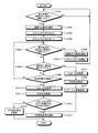
- FIG. 11 is a flowchart of an example of a first determination processing procedure of the mobile terminal apparatus 101 according to the first embodiment.
- the detection unit 603 determines whether or not the display state of the display 303 has changed from non-display to display (step S1101).
- the detection unit 603 waits for the display state of the display 303 to transition from non-display to display (step S1101: No).
- the detection unit 603 notifies the communication control unit 606 of a screen ON notification (step S1102) and starts the scan timer. (Step S1103).
- the update unit 607 determines whether a connection completion notification has been received from the communication control unit 606 (step S1104).
- the determination unit 605 determines whether or not a predetermined time T has elapsed since the start of the scan timer (step S1105). .
- step S1105: No when the predetermined time T has not elapsed (step S1105: No), the mobile terminal apparatus 101 returns to step S1104.
- step S1105: Yes when the predetermined time T has elapsed (step S1105: Yes), the determination unit 605 requests the acquisition unit 604 to acquire the Cell-ID of the cell Ci to which the own device belongs, and thereby the cell to which the own device belongs.
- the Cell-ID of Ci is acquired (step S1106).
- the determination unit 605 requests the communication control unit 606 to acquire the ESSID of the currently connected access point APj, thereby acquiring the ESSID of the currently connected access point APj (step S1107). Then, the determination unit 605 refers to the connection result table 500 and determines whether there is an ESSID stored in association with the Cell-ID of the cell Ci to which the own device belongs (step S1108).
- step S1108 Yes
- the determination unit 605 notifies the communication control unit 606 of a scan operation flag ON setting request (step S1109), and ends a series of processing according to this flowchart.
- step S1108 when there is no ESSID (step S1108: No), the determination unit 605 notifies the communication control unit 606 of a scan operation flag OFF setting request (step S1110), and ends a series of processes according to this flowchart.
- step S1104 when a connection completion notification is received from the communication control unit 606 (step S1104: Yes), the update unit 607 sends a request for acquiring the Cell-ID of the cell Ci to which the own device belongs to the acquisition unit 604. By doing so, the Cell-ID of the cell Ci to which the device belongs is obtained (step S1111).
- the updating unit 607 acquires the ESSID of the currently connected access point APj by making a request for acquiring the ESSID of the currently connected access point APj to the communication control unit 606 (step S1112). Then, the update unit 607 executes table update processing (step S1113), and ends a series of processing according to this flowchart.
- the table update process is a process for updating the stored contents of the connection result table 500. Specific processing contents of the table update processing will be described later with reference to FIG.
- the periodic access point APj is determined depending on whether or not the cell Ci to which the device belongs belongs to the access point APj. Can control the scanning operation. If a connection completion notification interrupt indicating that the connection with the access point APj has been completed before the predetermined time T has elapsed, the stored contents of the connection performance table 500 can be updated.
- step S1109 the determination unit 605 may read the scan operation flag and notify the communication control unit 606 of an ON setting request for the scan operation flag when the scan operation flag is OFF. Also, in step S1110, the determination unit 605 may read the scan operation flag and transmit a scan operation flag OFF setting request to the communication control unit 606 when the scan operation flag is ON. Further, the processing in step S1107 may be omitted.
- FIG. 12 is a flowchart of an example of a second determination processing procedure of the mobile terminal device 101 according to the first embodiment.
- the detection unit 603 determines whether or not the display state of the display 303 has changed from non-display to display (step S1201).
- the detection unit 603 waits for the display state of the display 303 to transition from non-display to display (step S1201: No).
- the detection unit 603 notifies the communication control unit 606 of a screen ON notification (step S1202) and starts the scan timer. (Step S1203).
- the determination unit 605 determines whether or not a predetermined time T has elapsed since the start of the scan timer (step S1204).
- the determination unit 605 waits for a predetermined time T to elapse after the scan timer is started (step S1204: No).
- the determination unit 605 requests the acquisition unit 604 to acquire the Cell-ID of the cell Ci to which the own device belongs, and thereby the cell to which the own device belongs.
- the Cell-ID of Ci is acquired (step S1205).
- the determination unit 605 requests the communication control unit 606 to acquire the ESSID of the currently connected access point APj, thereby acquiring the ESSID of the currently connected access point APj (step S1206). Then, the determination unit 605 determines whether or not the ESSID of the connected access point APj has been acquired (step S1207).
- the determination unit 605 refers to the connection result table 500 and determines whether there is an ESSID stored in association with the Cell-ID of the cell Ci to which the own device belongs. Is determined (step S1208).
- step S1208 Yes
- the determination unit 605 notifies the communication control unit 606 of an ON setting request for the scan operation flag (step S1209), and the series of processing according to this flowchart ends.
- step S1208 when there is no ESSID (step S1208: No), the determination unit 605 notifies the communication control unit 606 of a scan operation flag OFF setting request (step S1210), and ends a series of processing according to this flowchart.
- step S1207 when the ESSID is acquired (step S1207: Yes), the update unit 607 executes table update processing (step S1211), and ends a series of processes according to this flowchart.
- the periodic access point APj is determined depending on whether or not the cell Ci to which the device belongs belongs to the access point APj. Can control the scanning operation. If the connection with the access point APj is completed after the predetermined time T has elapsed, the stored contents of the connection result table 500 can be updated.
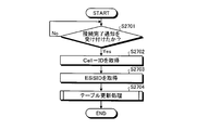
- FIG. 13 is a flowchart illustrating an example of a specific processing procedure of the table update processing.
- the update unit 607 first refers to the connection result table 500 and determines whether there is an ESSID stored in association with the Cell-ID of the cell Ci to which the own device belongs (step S1301).
- the update unit 607 acquires the current date and time (step S1302).
- the current date and time can be measured by, for example, a timer (not shown) included in the mobile terminal device 101.
- the updating unit 607 updates the last connection time stored in association with the Cell-ID of the cell Ci to which the own device belongs in the connection performance table 500 to the current date and time (step S1303). Terminate the process. Then, the mobile terminal device 101 returns to the step that called the table update process.
- step S1301 when there is no ESSID (step S1301: No), the update unit 607 acquires the current date and time (step S1304). Next, the update unit 607 adds Cell-ID, ESSID, and the current date and time to each field of the connection record table 500 (step S1305), and ends a series of processes according to this flowchart. Then, the mobile terminal device 101 returns to the step that called the table update process.
- the Cell-ID set in step S1305 is the Cell-ID of the cell Ci to which the own device belongs.
- the ESSID is the ESSID of the connected access point APj.
- FIG. 14 is a flowchart of an example of a first communication control processing procedure of the mobile terminal device 101 according to the first embodiment.
- the communication control unit 606 determines whether a screen ON notification has been received from the detection unit 603 (step S1401).
- the communication control unit 606 waits to receive a screen ON notification (step S1401: No). If the communication control unit 606 receives a screen ON notification (step S1401: Yes), the communication control unit 606 reads the ESSID table 400 (step S1402) and sets the scan operation flag to ON (step S1403).
- the communication control unit 606 determines whether or not the scan operation flag is ON (step S1404). If the scan operation flag is ON (step S1404: Yes), the communication control unit 606 acquires a scan result from the second communication unit 602 (step S1405).
- the communication control unit 606 determines whether or not the ESSID included in the scan result is registered in the ESSID table 400 (step S1406).
- the communication control unit 606 returns to step S1404.
- step S1406 Yes
- the communication control unit 606 controls the second communication unit 602 to start a connection process to the access point APj (step S1407). Then, the communication control unit 606 sets the scan operation flag to OFF (step S1408).
- the communication control unit 606 stores the ESSID of the access point APj that has started the connection process in the memory 302 (step S1409), and determines whether the connection process to the access point APj is completed (step S1410). ).
- the communication control unit 606 waits for the connection process to the access point APj to be completed (step S1410: No).
- the communication control unit 606 notifies the update unit 607 of a connection completion notification (step S1411), and ends the series of processes according to this flowchart. To do.
- step S1404 if the scan operation flag is OFF (step S1404: No), the communication control unit 606 controls the second communication unit 602 to stop the scan operation of the access point APj (step S1412). . And the communication control part 606 performs the stop process which stops the 2nd communication part 602 (step S1413), and complete
- connection completion notification interrupt can be generated.
- FIG. 15 is a flowchart of an example of a second communication control process procedure of the mobile terminal apparatus 101 according to the first embodiment.
- the communication control unit 606 determines whether an ON setting request has been received from the determination unit 605 (step S1501).
- step S1501 when an ON setting request is received (step S1501: Yes), the communication control unit 606 determines whether or not the scan operation flag is in an OFF state (step S1502). If the scan operation flag is ON (step S1502: No), the communication control unit 606 ends the series of processes according to this flowchart.
- step S1502 when the scan operation flag is OFF (step S1502: Yes), the communication control unit 606 sets the scan operation flag to ON (step S1503), and ends a series of processes according to this flowchart.
- step S1501 when the ON setting request is not received (step S1501: No), the communication control unit 606 determines whether an OFF setting request is received from the determination unit 605 (step S1504).
- step S1504 when an OFF setting request is received (step S1504: YES), the communication control unit 606 determines whether or not the scan operation flag is ON (step S1505). If the scan operation flag is OFF (step S1505: No), the communication control unit 606 ends the series of processes according to this flowchart.
- step S1505 Yes
- the communication control unit 606 sets the scan operation flag to OFF (step S1506), and ends a series of processes according to this flowchart.
- step S1504 if an OFF setting request has not been received (step S1504: No), the communication control unit 606 determines whether an ESSID acquisition request has been received (step S1507). If the ESSID acquisition request is not received (step S1507: NO), the communication control unit 606 returns to step S1501.
- step S1507: Yes the communication control unit 606 determines whether or not the access point APj is connected (step S1508). If the access point APj is currently connected (step S1508: YES), the communication control unit 606 reads the ESSID of the connected access point APj from the memory 302 (step S1509).
- the communication control unit 606 notifies the request source of the ESSID acquisition request of the read ESSID (step S1510), and ends the series of processes according to this flowchart. If the access point APj is not connected (step S1508: No), the communication control unit 606 notifies the request source of the ESSID acquisition request that there is no ESSID (step S1511), and performs a series of processing according to this flowchart. finish.
- FIG. 16 is a flowchart of an example of a third determination processing procedure of the mobile terminal device 101 according to the first embodiment.
- the detection unit 603 determines whether or not the display state of the display 303 has changed from non-display to display (step S1601).
- the detection unit 603 waits for the display state of the display 303 to change from non-display to display (step S1601: No). If the display state of the display 303 transitions from non-display to display (step S1601: Yes), the detection unit 603 notifies the communication control unit 606 of a screen ON notification (step S1602).
- the detection unit 603 resets the scan timer (step S1603) and starts the scan timer (step S1604). Then, the detection unit 603 determines whether the display state of the display 303 has changed from display to non-display (step S1605).
- step S1605 when the display state of the display 303 transitions from display to non-display (step S1605: Yes), the detection unit 603 notifies the communication control unit 606 of a screen OFF notification (step S1606). Then, the detection unit 603 stops the scan timer (step S1607) and returns to step S1601.
- step S1605 when the display state of the display 303 has not changed from display to non-display (step S1605: No), the update unit 607 determines whether a connection completion notification has been received from the communication control unit 606. (Step S1608). If the connection completion notification has not been received by the update unit 607 (step S1608: No), the determination unit 605 determines whether a predetermined time T has elapsed since the start of the scan timer (step S1609). .
- step S1609: No when the predetermined time T has not elapsed (step S1609: No), the mobile terminal apparatus 101 returns to step S1605.
- step S1609: Yes when the predetermined time T has elapsed (step S1609: Yes), the determination unit 605 requests the acquisition unit 604 to acquire the Cell-ID of the cell Ci to which the own device belongs, and thereby the cell to which the own device belongs.
- the Cell-ID of Ci is acquired (step S1610).
- the determination unit 605 requests the communication control unit 606 to acquire the ESSID of the currently connected access point APj, thereby acquiring the ESSID of the currently connected access point APj (step S1611). Then, the determination unit 605 refers to the connection result table 500 and determines whether there is an ESSID stored in association with the Cell-ID of the cell Ci to which the own device belongs (step S1612).
- step S1612 when there is an ESSID (step S1612: Yes), the determination unit 605 notifies the communication control unit 606 of a scan operation flag ON setting request (step S1613), and ends a series of processing according to this flowchart.
- step S1612 when there is no ESSID (step S1612: No), the determination unit 605 notifies the communication control unit 606 of a scan operation flag OFF setting request (step S1614), and ends a series of processing according to this flowchart.
- step S1608 If a connection completion notification is received from the communication control unit 606 in step S1608 (step S1608: Yes), the update unit 607 sends a request to acquire the Cell-ID of the cell Ci to which the own device belongs to the acquisition unit 604. By doing this, the Cell-ID of the cell Ci to which the device belongs is obtained (step S1615).
- the update unit 607 obtains the ESSID of the connected access point APj by making a request for obtaining the ESSID of the connected access point APj to the communication control unit 606 (step S1616). Then, the update unit 607 executes table update processing (step S1617), and ends a series of processing according to this flowchart.
- the scan timer can be stopped when the screen is turned off, and the process for determining whether or not there is a connection record to the access point APj after the predetermined time T has elapsed since the screen was turned on is prevented. be able to.
- FIG. 17 is a flowchart of an example of a third communication control processing procedure of the mobile terminal apparatus 101 according to the first embodiment.
- the communication control unit 606 determines whether a screen OFF notification has been received from the detection unit 603 (step S1701).
- the communication control unit 606 waits to receive a screen OFF notification from the detection unit 603 (step S1701: No).
- the communication control unit 606 determines whether the access point APj is currently connected (step S1702).
- step S1703 the communication control unit 606 determines whether or not the scan operation flag is ON (step S1703). If the scan operation flag is OFF (step S1703: NO), the communication control unit 606 proceeds to step S1706. On the other hand, when the scan operation flag is ON (step S1703: Yes), the communication control unit 606 sets the scan operation flag to OFF (step S1704).
- the communication control unit 606 controls the second communication unit 602 to stop the scanning operation of the access point APj (step S1705). And the communication control part 606 performs the stop process which stops the 2nd communication part 602 (step S1706), and complete
- step S1702 if the access point APj is currently connected (step S1702: Yes), the communication control unit 606 determines whether communication via the access point APj has been completed (step S1707). Here, the communication control unit 606 waits for the communication via the access point APj to end (step S1707: No).
- step S1707: Yes the communication control unit 606 determines whether or not a certain time t has elapsed since the communication via the access point APj was completed.
- Step S1708 the communication control unit 606 waits for the fixed time t to elapse (step S1708: No).
- step S1707 Yes
- the communication control unit 606 executes a stop process for stopping the second communication unit 602 (step S1706), and ends the series of processes according to this flowchart. To do.
- the elapsed time from the end of communication via the access point APj can be measured by a timer, for example.
- the scanning operation of the access point APj can be started when the display state of the display 303 transitions from non-display to display.
- the available access point APj can be searched without the user performing an operation input, and usability can be prevented from being impaired.
- the mobile terminal apparatus 101 after a predetermined time T has elapsed since the display state of the display 303 transitioned from non-display to display, it is determined whether or not there is a connection record to the access point APj in the cell Ci to which the own apparatus belongs. can do.
- the scanning operation can be continued. Thereby, even if the access point APj is not connected after the lapse of the predetermined time T, the scan operation is performed when it belongs to the cell Ci where there is a high possibility that the available access point APj exists compared to the cell Ci with no connection record. Can be continued. As a result, reconnectability to the access point APj can be improved and usability can be prevented from being impaired.
- the scanning operation can be stopped.
- the scan operation can be stopped if the access point APj is less likely to exist than the cell Ci having a connection record. As a result, it is possible to suppress power consumption required for the scan operation of the access point APj.
- the scan operation of the access point APj can be stopped. Thereby, the scanning operation of the access point APj when the display state of the display 303 is not displayed can be suppressed, and the power consumption of the mobile terminal apparatus 101 can be suppressed.
- the scanning operation can be started when the screen is turned on. For this reason, when the access point APj to which the same ESSID as the available access point AP is assigned exists in the vicinity of the mobile terminal apparatus 101, the access point APj can be connected to the network 210 via the access point APj.
- connection record table 500 when new connection record information is registered in the connection record table 500, it is determined whether or not the total number M of connection record information registered in the connection record table 500 is equal to or greater than a threshold value Mmax. can do. Also, according to the mobile terminal device 101, when the total number M is equal to or greater than the threshold value Mmax , the connection result information with the oldest last connection time can be deleted from the connection result information registered in the connection result table 500. . Thereby, an increase in the number of records in the connection record table 500 can be suppressed, and an increase in the storage area used for storing the connection record table 500 can be suppressed.
- the mobile terminal apparatus 101 concerning Embodiment 1 while suppressing the power consumption concerning the scanning operation
- FIG. 18 is an explanatory diagram showing an example of scanning operation of the access point APj. As shown in FIG. 18, the scan operation includes an active scan and a passive scan.
- the active scan is a scan operation for detecting the access point APj by transmitting a probe request signal to each channel used in the wireless LAN and receiving a probe response signal.
- a frequency band of 2.4 [GHz] is used.
- 13 channels in the 2.4 [GHz] frequency band of IEEE (The Institute of Electrical and Electronics Engineers, Inc.) 802.11 are used as wireless LAN channels used for active scanning. is there.
- the passive scan is a scan operation for detecting the access point APj by receiving a signal (packet) called a beacon from the access point APj.
- a signal packet
- a beacon from the access point APj.
- a frequency band of 5 [GHz] is used.
- wireless LAN channels used for passive scanning include IEEE 802.11 W52 (type) 4 channels, W53 (type) 4 channels, and W56 (type) 11 channels. There is.
- the time required for active scanning of one channel is, for example, about 15 to 30 [ms]. Further, the time required for one channel passive scan is, for example, about 220 [ms]. This is because a beacon transmission cycle from the access point APj is about 102.4 [ms], so that a time during which a beacon can be received twice is secured.
- the determination unit 605 determines whether or not the scanning operation of the access point APj has been performed a predetermined number of times F since the display state of the display 303 has changed from non-display to display. Then, when the scanning operation has been performed a predetermined number of times F, the determination unit 605 refers to the connection result table 500 and determines that the ESSID of the access point APj stored in association with the Cell-ID of the cell Ci to which the own device belongs is stored. It is determined whether or not there is.
- the determination unit 605 determines that there is a connection record to the access point APj in the cell Ci to which the own device belongs.
- the determination unit 605 determines that there is no connection record to the access point APj in the cell Ci to which the own device belongs.
- the predetermined number of times F can be arbitrarily set.
- the predetermined number of times F is set on the assumption that the mobile terminal apparatus 101 may not be able to search for an access point APj existing in the vicinity by one scanning operation.
- the predetermined number F is, for example, 3 [times] or 5 [times] and is stored in the memory 302.
- the mobile terminal apparatus 101 may perform either an active scan or a passive scan operation, or perform both an active scan and a passive scan operation. Also good.
- FIG. 19 is an explanatory diagram of an operation example of the mobile terminal apparatus 101 according to the second embodiment.
- the operation example of the mobile terminal apparatus 101 shown in FIG. 19 is an operation example when there is no connection record to the access point APj in the cell Ci to which the own apparatus belongs.
- the detection unit 603 detects that the display state of the display 303 has changed from non-display to display. In the example of FIG. 19, it is detected that the display state of the display 303 has changed from non-display to display as a result of the display state of the display 303 being switched from non-display to display by a user operation input.
- the detection unit 603 When the detection unit 603 detects that the display state of the display 303 has changed from non-display to display, the detection unit 603 notifies the communication control unit 606 of a screen ON notification.
- the communication control unit 606 controls the second communication unit 602 to start the access point APj detection operation.
- the communication control unit 606 reads the ESSID table 400 and determines whether or not the ESSID included in the scan result from the second communication unit 602 is registered in the ESSID table 400.
- the communication control unit 606 controls the second communication unit 602 to start a connection operation to the access point APj.
- the communication control unit 606 does not start the connection operation to the access point APj.
- the connection operation to the access point APj is not started.
- the communication control unit 606 notifies the determination unit 605 of the scan completion notification when the scan operation of the access point APj is performed a predetermined number of times F.
- the scan completion notification indicates that the scan operation of the access point APj has been performed a predetermined number of times F.
- the determination unit 605 When the determination unit 605 receives a scan completion notification from the communication control unit 606, the determination unit 605 requests the acquisition unit 604 to acquire the Cell-ID of the cell Ci to which the own device belongs.
- the Cell-ID of the cell Ci to which it belongs is acquired.
- the Cell-ID “C3” of the cell C3 to which the own device belongs is acquired.
- the determination unit 605 requests the communication control unit 606 to acquire the ESSID of the currently connected access point APj, thereby acquiring the ESSID of the currently connected access point APj.
- “no ESSID” indicating that the access point APj is not connected is notified from the communication control unit 606 to the determination unit 605.
- the determination unit 605 reads the connection result table 500 and determines whether or not there is a connection result to the access point APj in the cell Ci to which the own device belongs. In the example of FIG. 19, since the connection record information corresponding to the acquired Cell-ID “C3” is not registered, it is determined that there is no connection record to the access point APj.
- the determination unit 605 transmits a scan operation flag OFF setting request to the communication control unit 606.
- the communication control unit 606 returns Ack to the determination unit 605 when receiving the scan operation flag OFF setting request, and sets the scan operation flag to OFF when the scan operation flag is ON. To do. As a result, the periodic scanning operation of the access point APj by the second communication unit 602 is stopped.
- the mobile terminal apparatus 101 it is possible to start a scan operation of the access point APj periodically when the screen is turned on.
- the access point APj is not connected to the access point APj even if the scan operation of the access point APj is performed a predetermined number of times F, the periodic scan operation of the access point APj can be stopped.
- FIG. 20 is a flowchart of an example of a determination process procedure of the mobile terminal apparatus 101 according to the second embodiment.
- the detection unit 603 determines whether or not the display state of the display 303 has transitioned from non-display to display (step S2001).
- the detection unit 603 waits for the display state of the display 303 to change from non-display to display (step S2001: No).
- the detection unit 603 notifies the communication control unit 606 of a screen ON notification (step S2002).
- the determination unit 605 determines whether a scan completion notification has been received from the communication control unit 606 (step S2003). Here, the determination unit 605 waits to receive a scan completion notification from the communication control unit 606 (step S2003: No).
- the determination unit 605 requests the acquisition unit 604 to acquire the Cell-ID of the cell Ci to which the own device belongs, and thereby the cell to which the own device belongs.
- the Cell-ID of Ci is acquired (step S2004).
- the determination unit 605 acquires the ESSID of the connected access point APj by making a request for acquiring the ESSID of the connected access point APj to the communication control unit 606 (step S2005). Then, the determination unit 605 determines whether or not the ESSID of the connected access point APj has been acquired (step S2006).
- the determination unit 605 refers to the connection performance table 500 and determines whether there is an ESSID stored in association with the Cell-ID of the cell Ci to which the device belongs. Is determined (step S2007).
- step S2007: Yes the determination unit 605 notifies the communication control unit 606 of a scan operation flag ON setting request (step S2008), and ends a series of processing according to this flowchart.
- step S2007: No the determination unit 605 notifies the communication control unit 606 of a scan operation flag OFF setting request (step S2009), and ends a series of processes according to this flowchart.
- step S2006 when the ESSID is acquired (step S2006: Yes), the update unit 607 executes table update processing (step S2010), and ends a series of processes according to the flowchart.
- step S2010 is the same as the specific processing procedure of the table update processing shown in FIG.
- FIG. 21 is a flowchart of an example of a communication control processing procedure of the mobile terminal apparatus 101 according to the second embodiment.
- the communication control unit 606 determines whether a screen ON notification has been received from the detection unit 603 (step S2101).
- the communication control unit 606 waits to receive a screen ON notification (step S2101: No).
- the communication control unit 606 receives a screen ON notification (step S2101: Yes)
- the communication control unit 606 reads the ESSID table 400 (step S2102).
- the communication control unit 606 resets the scan counter f (step S2103).
- the scan counter f is a counter that counts the number of times that the access point APj is scanned.
- the scan counter f is realized by a register of the memory 302 or the CPU 301, for example.
- the communication control part 606 controls the 2nd communication part 602, and performs the scanning operation
- the communication control unit 606 acquires a scan result from the second communication unit 602 (step S2105).
- the communication control unit 606 determines whether or not the ESSID included in the scan result is registered in the ESSID table 400 (step S2106). If the ESSID is not registered (step S2106: NO), the communication control unit 606 increments the scan counter f (step S2107).
- the communication control unit 606 determines whether “f” of the scan counter f has reached “F” a predetermined number of times F (step S2108). If “f” is not “F” (step S2108: NO), the communication control unit 606 returns to step S2104.
- step S2108 Yes
- the communication control unit 606 notifies the determination unit 605 of a scan completion notification (step S2109), and ends a series of processing according to this flowchart. To do.
- step S2106 when the ESSID is registered (step S2106: Yes), the communication control unit 606 executes connection processing to the access point APj (step S2110), and ends a series of processing according to this flowchart. To do.
- the scanning operation of the access point APj can be performed a predetermined number of times F when the screen is turned on.
- the determination unit 605 can be notified of a scan completion notification.
- the mobile terminal apparatus 101 determines whether or not the scanning operation of the access point APj has been performed a predetermined number of times F since the display state of the display 303 has changed from non-display to display. Can be determined. Further, according to the mobile terminal apparatus 101, when the scanning operation of the access point APj is performed a predetermined number of times F, it is possible to determine whether or not there is a connection record to the access point APj in the cell Ci to which the own apparatus belongs.
- the presence / absence of connection to the access point APj is determined after the elapse of the predetermined time T from the screen ON, and the scanning operation of the access point APj is controlled based on the determination result.
- the presence / absence of connection to the access point APj is determined when the screen is ON, and the scanning operation of the access point APj is controlled based on the determination result after a predetermined time T has elapsed.
- FIG. 22 is an explanatory diagram (part 1) of an operation example of the mobile terminal device 101 according to the third embodiment.
- the operation example of the mobile terminal apparatus 101 shown in FIG. 22 is an operation example when there is no connection record to the access point APj in the cell Ci to which the own apparatus belongs.
- the detection unit 603 detects that the display state of the display 303 has changed from non-display to display. In the example of FIG. 22, it is detected that the display state of the display 303 has changed from non-display to display as a result of the display state of the display 303 being switched from non-display to display by a user operation input.
- the determination unit 605 detects that the display state of the display 303 has changed from non-display to display, the determination unit 605 sends a request to acquire the Cell-ID of the cell Ci to which the own device belongs to the acquisition unit 604. By doing so, the Cell-ID of the cell Ci to which the device belongs is obtained. In the example of FIG. 22, the Cell-ID “C3” of the cell C3 to which the own device belongs is acquired.
- the determination unit 605 reads the connection result table 500 and determines whether or not there is a connection result to the access point APj in the cell Ci to which the own device belongs. In the example of FIG. 22, it is determined that there is no connection record to the access point APj because the connection record information corresponding to the acquired Cell-ID “C3” is unregistered.
- the determination unit 605 When there is no connection record, the determination unit 605 generates a screen ON notification and an OFF setting request (predetermined time T) for requesting the scan operation flag to be turned off after the predetermined time T has elapsed. To 606.
- the communication control unit 606 When receiving the screen ON notification and the OFF setting request (predetermined time T), the communication control unit 606 starts the scan timer and controls the second communication unit 602 to control the access point APj. The detection operation is started.
- the communication control unit 606 reads the ESSID table 400 and determines whether or not the ESSID included in the scan result from the second communication unit 602 is registered in the ESSID table 400.
- the communication control unit 606 controls the second communication unit 602 to start a connection operation to the access point APj.
- the communication control unit 606 does not start the connection operation to the access point APj.
- the connection operation to the access point APj is not started.
- the communication control unit 606 sets the scan operation flag to OFF when the scan operation flag is ON after a predetermined time T has elapsed since the start of the scan timer. As a result, the periodic scanning operation of the access point APj by the second communication unit 602 is stopped.
- the mobile terminal device 101 when the screen is turned on, it is determined whether or not there is a connection record to the access point APj in the cell Ci to which the own device belongs, and the scanning operation of the periodic access point APj is started. can do. If the access point APj is not connected even after a predetermined time T has elapsed since the screen was turned on, the periodic scanning operation of the access point APj can be stopped.
- FIG. 23 is an explanatory diagram (part 2) of an operation example of the mobile terminal device 101 according to the third embodiment.
- the operation example of the mobile terminal apparatus 101 shown in FIG. 23 is an operation example when there is a connection record to the access point APj in the cell Ci to which the own apparatus belongs.
- the detection unit 603 detects that the display state of the display 303 has changed from non-display to display. In the example of FIG. 23, it is detected that the display state of the display 303 has changed from non-display to display as a result of the display state of the display 303 being switched from non-display to display by a user operation input.
- the determination unit 605 detects that the display state of the display 303 has changed from non-display to display, the determination unit 605 sends a request to acquire the Cell-ID of the cell Ci to which the own device belongs to the acquisition unit 604. By doing so, the Cell-ID of the cell Ci to which the device belongs is obtained. In the example of FIG. 23, the Cell-ID “C1” of the cell C1 to which the own device belongs is acquired.
- the determination unit 605 reads the connection result table 500 and determines whether or not there is a connection result to the access point APj in the cell Ci to which the own device belongs. In the example of FIG. 23, since the connection record information corresponding to the acquired Cell-ID “C1” has been registered, it is determined that there is a connection record to the access point APj.
- the determination unit 605 transmits a screen ON notification to the communication control unit 606.
- the communication control unit 606 controls the second communication unit 602 to start the scanning operation of the access point APj.
- the communication control unit 606 reads the ESSID table 400 and determines whether or not the ESSID included in the scan result from the second communication unit 602 is registered in the ESSID table 400.
- the communication control unit 606 controls the second communication unit 602 to start a connection operation to the access point APj.
- the communication control unit 606 does not start the connection operation to the access point APj.
- the connection operation to the access point APj is not started.
- the mobile terminal device 101 when the screen is turned on, it is determined whether or not there is a connection record to the access point APj in the cell Ci to which the own device belongs, and the scanning operation of the periodic access point APj is started. can do. Even if the access point APj is disconnected after a predetermined time T from the screen ON, if there is a connection record to the access point APj in the cell Ci to which the device belongs, a periodic scan of the access point APj is performed. Can be continued.
- FIG. 24 is an explanatory diagram (part 3) of an operation example of the mobile terminal device 101 according to the third embodiment.
- the update unit 607 sends a connection completion notification (interrupt) from the communication control unit 606. It is an operation example when accepting (notification).
- the detection unit 603 detects that the display state of the display 303 has changed from non-display to display. In the example of FIG. 24, it is detected that the display state of the display 303 has transitioned from non-display to display as a result of the display state of the display 303 being switched from non-display to display by a user operation input.
- the determination unit 605 When the determination unit 605 detects that the display state of the display 303 has changed from non-display to display, the determination unit 605 sends a request to acquire the Cell-ID of the cell Ci to which the own device belongs to the acquisition unit 604. By doing so, the Cell-ID of the cell Ci to which the device belongs is obtained. In the example of FIG. 24, the Cell-ID “C3” of the cell C3 to which the own device belongs is acquired.
- the determination unit 605 reads the connection result table 500 and determines whether or not there is a connection result to the access point APj in the cell Ci to which the own device belongs. In the example of FIG. 24, since the connection record information corresponding to the acquired Cell-ID “C3” is not registered, it is determined that there is no connection record to the access point APj.
- the determination unit 605 When there is no connection record, the determination unit 605 generates a screen ON notification and an OFF setting request (predetermined time T) for requesting the scan operation flag to be turned off after the predetermined time T has elapsed. To 606.
- the communication control unit 606 When receiving the screen ON notification and the OFF setting request (predetermined time T), the communication control unit 606 starts the scan timer and controls the second communication unit 602 to control the access point APj. The detection operation is started.
- the communication control unit 606 controls the second communication unit 602 to connect to the access point APj. To start.
- connection completion notification When the communication control unit 606 receives the connection completion notification from the second communication unit 602, the communication control unit 606 stores the ESSID of the access point AP1 that has completed the connection in the memory 302, and notifies the update unit 607 of the connection completion notification To be notified.
- the connection completion notification includes the ESSID of the access point AP1 that has been connected.
- the update unit 607 obtains the Cell-ID of the cell Ci to which the own device belongs by making a request for obtaining the Cell-ID of the cell Ci to which the own device belongs to the obtaining unit 604.
- the Cell-ID “C3” of the cell C3 to which the own device belongs is acquired.
- the update unit 607 updates the stored contents of the connection record table 500.
- the Cell-ID “C3” of the cell C3 to which the mobile terminal apparatus 101 belongs and the ESSID “AP1” of the access point AP1 are not registered in each field in the connection result table 500, the Cell-ID “C3”, the ESSID “AP1” of the access point AP1 being connected, and the last connection time “2011.05.3.10.003” are additionally set.
- new connection record information 500-4 is newly registered in the connection record table 500 as a record.
- the mobile terminal apparatus 101 it is possible to start a scan operation of the access point APj periodically when the screen is turned on.
- the storage content of the connection performance table 500 can be updated.
- FIG. 25 is a flowchart of an example of a determination processing procedure of the mobile terminal apparatus 101 according to the third embodiment.
- the detection unit 603 determines whether or not the display state of the display 303 has changed from non-display to display (step S2501).
- the detection unit 603 waits for the display state of the display 303 to transition from non-display to display (step S2501: No).
- the determination unit 605 requests the acquisition unit 604 to acquire the Cell-ID of the cell Ci to which the own device belongs.
- the Cell-ID of the cell Ci to which the own device belongs is acquired (step S2502).
- the determination unit 605 refers to the connection result table 500 and determines whether there is an ESSID stored in association with the Cell-ID of the cell Ci to which the own device belongs (step S2503).
- step S2503 if there is an ESSID (step S2503: Yes), the determination unit 605 notifies the communication control unit 606 of a screen ON notification (step S2504), and ends a series of processing according to this flowchart.
- the determination unit 605 may notify the communication control unit 606 of a scanning operation continuation request for requesting to continue the scanning operation together with the screen ON notification.
- the determination unit 605 notifies the communication control unit 606 of a screen ON notification and an OFF setting request (predetermined time T) (step S2505).
- the OFF setting request (predetermined time T) is a request to turn off the scanning operation flag after the elapse of the predetermined time T.
- FIG. 26 is a flowchart of an example of a communication control processing procedure of the mobile terminal apparatus 101 according to the third embodiment.
- the communication control unit 606 determines whether a screen ON notification has been received from the determination unit 605 (step S2601).
- the communication control unit 606 waits to receive a screen ON notification (step S2601: No). If the communication control unit 606 receives a screen ON notification (step S2601: Yes), the communication control unit 606 determines whether an OFF setting request (predetermined time T) is received from the determination unit 605 (step S2602).
- step S2602 When the communication control unit 606 receives an OFF setting request (predetermined time T) (step S2602: YES), the communication control unit 606 starts a scan timer (step S2603) and sets the scan operation flag to ON (step S2604). ).
- the communication control unit 606 determines whether or not a predetermined time T has elapsed since the start of the scan timer (step S2605).
- the predetermined time T has not elapsed (step S2605: No)
- the communication control unit 606 acquires a scan result from the second communication unit 602 (step S2606).
- the communication control unit 606 determines whether or not the ESSID included in the scan result is registered in the ESSID table 400 (step S2607).
- the communication control unit 606 returns to step S2605.
- step S2607 Yes
- the communication control unit 606 controls the second communication unit 602 to start a connection process to the access point APj (step S2608). Then, the communication control unit 606 sets the scan operation flag to OFF (step S2609).
- the communication control unit 606 stores the ESSID of the access point APj that has started the connection process in the memory 302 (step S2610), and determines whether the connection process to the access point APj is completed (step S2611). ).
- the communication control unit 606 waits for the connection process to the access point APj to be completed (step S2611: No).
- the communication control unit 606 notifies the update unit 607 of a connection completion notification (step S2612), and ends the series of processes according to this flowchart. To do.
- step S2605 when the predetermined time T has elapsed (step S2605: Yes), the communication control unit 606 sets the scan operation flag to OFF (step S2613) and stops the second communication unit 602. Is executed (step S2614), and a series of processes according to this flowchart is terminated.
- step S2602 if the communication control unit 606 has not received an OFF setting request (predetermined time T) (step S2602: No), the communication control unit 606 executes a scan control process (step S2615), and a series of processes according to this flowchart. Exit.
- the specific processing procedure of the scan control process is the same as that in steps S1403 to S1413 shown in FIG.
- the screen when the screen is turned on, it is possible to determine whether or not there is a connection record to the access point APj in the cell Ci to which the own device belongs. If the access point APj is not connected even after a predetermined time T has elapsed since the screen was turned ON, the periodic access point APj changes depending on whether or not the cell Ci to which the device belongs belongs to the access point APj.
- the scanning operation can be controlled.
- FIG. 27 is a flowchart of an example of an update process procedure of the mobile terminal device 101 according to the third embodiment.
- the update unit 607 determines whether or not a connection completion notification has been received from the communication control unit 606 (step S2701).
- the update unit 607 waits to receive a connection completion notification from the communication control unit 606 (step S2701: No).
- the update unit 607 requests the acquisition unit 604 to acquire the Cell-ID of the cell Ci to which the own device belongs.
- the Cell-ID of the cell Ci to which the own device belongs is acquired (step S2702).
- the update unit 607 acquires the ESSID of the connected access point APj by making a request for acquiring the ESSID of the connected access point APj to the communication control unit 606 (step S2703). Then, the update unit 607 executes table update processing (step S2704), and ends a series of processing according to this flowchart.
- connection result table 500 can be updated.
- the specific process procedure of the table update process is the same as the specific process procedure of the table update process shown in FIG.
- the presence / absence of connection results to the access point APj is determined when the screen is ON, and after a predetermined time T has elapsed, based on the determination result, The scanning operation of the access point APj can be controlled.
- the control method described in the present embodiment can be realized by executing a program prepared in advance on a computer such as a personal computer or a workstation.
- This control program is recorded on a computer-readable recording medium such as a hard disk, a flexible disk, a CD-ROM, an MO, and a DVD, and is executed by being read from the recording medium by the computer.
- the control program may be distributed via a network such as the Internet.
- the mobile terminal device 101 described in the present embodiment is a PLD (Programmable) such as a standard cell or a specific application IC (hereinafter simply referred to as “ASIC”) such as a structured ASIC (Application Specific Integrated Circuit). It can also be realized by Logic Device. Specifically, for example, by defining the functions (first communication unit 601 to update unit 607) of the mobile terminal device 101 described above by HDL description, logically synthesizing the HDL description and giving it to the ASIC or PLD The mobile terminal device 101 can be manufactured.
- ASIC Application Specific Integrated Circuit
Abstract
移動端末装置(101)は、画面(110)の表示状態が非表示から表示へ遷移したことを検出する。移動端末装置(101)は、基地局(102)のセル(C)において、画面(110)の表示状態が非表示から表示へ遷移したことを検出した場合、基地局(102)のセル(C)に含まれるアクセスポイント(103)のスキャン動作を開始する。移動端末装置(101)は、画面(110)の表示状態が非表示から表示へ遷移したことを検出した場合、所定時間(T)の経過後に、自装置が属する基地局(102)のエリア識別情報を含むエントリが接続履歴情報(120)から検索されたかを判定する。移動端末装置(101)は、所定時間(T)の経過後に、基地局(102)のエリア識別情報を含むエントリが接続履歴情報(120)から検索されたかを判定した判定結果に基づいて、アクセスポイント(103)のスキャン動作を制御する。
Description
本発明は、移動端末装置、制御方法および制御プログラムに関する。
従来、携帯電話網に接続する通信機能と、無線LAN(Local Area Network)に接続する通信機能とを有する移動端末装置がある。移動端末装置は、例えば、各地に設置されている携帯電話網の基地局や無線LANのアクセスポイントを介して、インターネットなどのネットワークに接続することができる。
関連する先行技術としては、例えば、セルラネットワークの基地局からの受信信号の電界強度に基づき端末の位置を検出し、基地局のセルIDおよび受信信号電界強度に基づき、無線LANへの接続ポイントの位置を検出する技術がある。
しかしながら、従来技術によれば、無線LANなどのアクセスポイントを探索する移動端末装置のスキャン動作により、移動端末装置の消費電力の増大化を招くという問題がある。例えば、ハンドオーバーが行われた際に無線LANのアクセスポイントを探索するスキャン動作を開始する場合、ハンドオーバーが頻繁に行われることにより、アクセスポイントを探索するスキャン動作にかかる移動端末装置の消費電力が増大する。
1つの側面では、本発明は、電力の消費を抑制することができる移動端末装置、制御方法および制御プログラムを提供することを目的とする。
本発明の一側面によれば、基地局に接続を行う第1の通信部と、アクセスポイントを介してネットワークに接続を行う第2の通信部と、基地局の通信エリアを識別するエリア識別情報と前記通信エリアにおいて前記ネットワークに接続が行われたアクセスポイントを識別するアクセスポイント識別情報とを対応付けたエントリを複数含む接続履歴情報を記憶する記憶部を有する移動端末装置が有する検出部が、画面が表示されていない非表示状態から前記画面が表示された表示状態に遷移したことを検出し、前記移動端末装置が有する判定部が、第1の基地局の通信エリアにおいて、前記画面が前記非表示状態から前記表示状態に遷移したことを前記検出部が検出した場合、所定時間経過後に前記第1の基地局の通信エリアに含まれるアクセスポイントの探索を前記第2の通信部に開始させるとともに、前記第1の基地局の第1のエリア識別情報を含むエントリが前記接続履歴情報から検索されたかを判定し、前記移動端末装置が有する制御部が、前記所定時間経過後、前記判定部が判定した結果に基づき、前記第2の通信部を制御する移動端末装置、制御方法および制御プログラムが提案される。
本発明の一態様によれば、電力の消費を抑制することができるという効果を奏する。
以下に添付図面を参照して、本発明にかかる移動端末装置、制御方法および制御プログラムの実施の形態を詳細に説明する。
(実施の形態1)
図1は、実施の形態1にかかる制御方法の一実施例を示す説明図である。図1において、移動端末装置101は、各種情報を表示する画面110を有し、基地局102およびアクセスポイント103と無線通信可能なコンピュータである。具体的には、例えば、移動端末装置101は、スマートフォン、携帯電話機、タブレット型PC(Personal Computer)、PHS(Personal Handy-phone System)などである。
図1は、実施の形態1にかかる制御方法の一実施例を示す説明図である。図1において、移動端末装置101は、各種情報を表示する画面110を有し、基地局102およびアクセスポイント103と無線通信可能なコンピュータである。具体的には、例えば、移動端末装置101は、スマートフォン、携帯電話機、タブレット型PC(Personal Computer)、PHS(Personal Handy-phone System)などである。
基地局102およびアクセスポイント103は、各々の通信エリアに存在する移動端末装置101と無線通信可能であり、例えば、移動端末装置101がネットワークに接続するための拠点となる無線局である。具体的には、例えば、基地局102は、各地に点在する移動体通信網(携帯電話網)の基地局である。また、アクセスポイント103は、例えば、各地に点在する無線LANのアクセスポイントである。
移動端末装置101は、基地局102およびアクセスポイント103をそれぞれ異なる検出動作により検出し、検出した基地局102やアクセスポイント103を介してネットワークに接続することができる。ネットワークは、例えば、移動体通信網、LAN、WAN(Wide Area Network)、インターネットなどである。
ここで、検出動作とは、各地に点在する基地局102およびアクセスポイント103の中から通信可能な基地局102やアクセスポイント103を探索するいわゆるスキャン動作である。基地局102およびアクセスポイント103を検出する検出動作は、例えば、無線通信の通信方式、通信規格、通信性能、通信サービスなどの違いによりそれぞれ異なる。
すなわち、移動端末装置101は、アクセスポイント103を検出するために、基地局102を検出する検出動作とは異なる別の検出動作を行う。このため、移動端末装置101は、基地局102を検出するための検出動作により電力を消費し、アクセスポイント103を検出するための検出動作により電力を消費する。
以下の説明では、基地局102の一例として、移動体通信網の基地局を例に挙げ、アクセスポイント103の一例として、無線LANのアクセスポイントを例に挙げて説明する。また、基地局102の通信エリアを「セルC」と表記する場合がある。
図1の例では、移動体通信網の基地局102として、基地局102-1~102-3が示され、無線LANのアクセスポイント103として、アクセスポイント103-1~103-12が示されている。また、基地局102-1~102-3のセルC1~C3と、アクセスポイント103-1~103-12の通信エリアA1~A12が示されている。
ここで、無線LANのアクセスポイント103は、例えば、移動体通信網の基地局102に比べて、最大通信速度が速く伝送効率が高い一方で、通信エリアが狭い傾向にある。また、無線LANのアクセスポイント103は、特定のサービスに加入しているユーザしか利用できないものも多い。
移動端末装置101の周辺に利用可能なアクセスポイント103が存在しない場合に、移動端末装置101がアクセスポイント103の検出動作を行うことは望ましくない。また、アクセスポイント103を利用する際に、アクセスポイント103の検出動作の開始をユーザが指示することが考えられるが、ユーザの操作入力が必要になるとともに、利用可能なアクセスポイント103の設置位置をユーザが把握していない場合がある。
そこで、実施の形態1では、移動端末装置101は、画面110が非表示状態から表示状態へ遷移したことを契機に、無線LANのアクセスポイント103のスキャン動作を開始する。また、移動端末装置101は、所定時間Tの経過後に、アクセスポイント103に非接続の場合、自装置が属するセルCにおけるアクセスポイント103への接続履歴の有無を判定する。そして、移動端末装置101は、アクセスポイント103への接続履歴がある場合にスキャン動作を継続させ、アクセスポイント103への接続履歴がない場合にスキャン動作を停止させる。
これにより、移動端末装置101は、ユーザビリティが損なわれることを防ぐとともに、アクセスポイント103のスキャン動作にかかる消費電力を抑制する。なお、移動体通信網の基地局102を検出する検出動作については、例えば、移動端末装置101により周期的に行われる場合を想定する。以下、実施の形態1にかかる移動端末装置101の通信制御処理の一実施例について説明する。
(1)移動端末装置101は、画面110が表示されていない非表示状態から画面110が表示された表示状態に遷移したことを検出する。ここで、非表示状態(画面OFF)とは、例えば、画面110に対する電力供給が停止された状態である。また、表示状態(画面ON)とは、例えば、画面110に対する電力供給が行われている状態である。
以下の説明では、画面110が表示されていない非表示状態を「画面110の表示状態が非表示」と表記し、画面110が表示された表示状態を「画面110の表示状態が表示」と表記する場合がある。
(2)移動端末装置101は、基地局102のセルCにおいて、画面110の表示状態が非表示から表示へ遷移したことを検出した場合、基地局102のセルCに含まれるアクセスポイント103のスキャン動作を開始する。アクセスポイント103が探索された場合、移動端末装置101は、探索されたアクセスポイント103を識別するアクセスポイント識別情報を含むエントリを接続情報120から検索する。そして、移動端末装置101は、探索されたアクセスポイント103を識別するアクセスポイント識別情報を含むエントリが接続情報120から検索されたかを判定する。
ここで、接続情報120は、インターネットなどのネットワークに接続が行われたアクセスポイント103、すなわち、利用可能なアクセスポイント103のアクセスポイント識別情報を特定する情報である。アクセスポイント識別情報は、例えば、アクセスポイント103のESSID(Extended Service Set Identifier)やBSSID(Basic Service Set Identifier)などである。
また、アクセスポイント識別情報は、複数のアクセスポイント103に同一のものが付与される場合がある。同一のアクセスポイント識別情報が付与されるアクセスポイント103の一例としては、例えば、利用可能な通信サービスが同一のアクセスポイントの集合や、ある企業が経営している複数の店舗の各々に設置されたアクセスポイントの集合などがある。このため、探索されたアクセスポイント103を移動端末装置101のユーザが利用したことがない場合であっても、探索されたアクセスポイント103を識別するアクセスポイント識別情報が接続情報120から検索されることがある。
接続情報120からエントリが検索された場合、移動端末装置101は、探索されたアクセスポイント103への接続動作を行う。アクセスポイント103への接続動作とは、アクセスポイント103を介してインターネットなどのネットワークに接続する接続処理である。この結果、移動端末装置101は、アクセスポイント103を介して、インターネットなどのネットワークに接続することができる。一方、アクセスポイント103が探索されなかった、または、接続情報120からエントリが検索されなかった場合、移動端末装置101は、アクセスポイント103のスキャン動作を繰り返す。
(3)移動端末装置101は、画面110の表示状態が非表示から表示へ遷移したことを検出した場合、所定時間Tの経過後に、自装置が属する基地局102のエリア識別情報を含むエントリが接続履歴情報130から検索されたかを判定する。ここで、接続履歴情報130は、基地局102のセルCを識別するエリア識別情報と、基地局102のセルCにおいてインターネットなどのネットワークに接続が行われたアクセスポイント103を識別するアクセスポイント識別情報と、を対応付けたエントリを含む。
具体的には、例えば、接続履歴情報130は、基地局102のセル群(例えば、セルC1~C3)のうちアクセスポイント103への接続動作が行われたセルCを特定する情報である。アクセスポイント103への接続動作とは、アクセスポイント103を介してネットワークに接続する動作である。
また、アクセスポイント103への接続履歴とは、アクセスポイント103への移動端末装置101の接続処理が正常に完了した履歴である。アクセスポイント103への接続処理では、例えば、移動端末装置101のユーザの認証処理などが行われる。すなわち、アクセスポイント103への接続履歴があるセルCは、アクセスポイント103への接続履歴がないセルCに比べて、移動端末装置101のユーザが利用可能なアクセスポイント103が存在する可能性が高いセルCである。
また、所定時間Tは、例えば、アクセスポイント103のスキャン動作を複数回行える程度の時間に設定される。所定時間Tは、画面110の表示状態が非表示から表示へ遷移してからの経過時間であってもよく、また、アクセスポイント103のスキャン動作を開始してからの経過時間であってもよい。
具体的には、例えば、移動端末装置101は、画面110の表示状態が表示へ遷移してから所定時間Tの経過後にアクセスポイント103に非接続の場合に、自装置が属する基地局102のエリア識別情報を含むエントリを接続履歴情報130から検索してもよい。そして、移動端末装置101は、自装置が属する基地局102のエリア識別情報を含むエントリが接続履歴情報130から検索されたかを判定する。
なお、図1中、太線の丸で表すアクセスポイント103の通信エリアは、移動端末装置101の接続履歴があるアクセスポイント103の通信エリアを表している。また、図1中、点線の丸で表すアクセスポイント103の通信エリアは、移動端末装置101の接続履歴があるアクセスポイント103と同一のアクセスポイント識別情報が付与されたアクセスポイント103の通信エリアを表している。
(4)移動端末装置101は、所定時間Tの経過後に、基地局102のエリア識別情報を含むエントリが接続履歴情報130から検索されたかを判定した判定結果に基づいて、アクセスポイント103のスキャン動作を制御する。
具体的には、例えば、所定時間Tの経過後に基地局102のエリア識別情報を含むエントリが接続履歴情報130から検索された場合、移動端末装置101は、基地局102のセルCに含まれるアクセスポイント103の探索を継続する。すなわち、所定時間Tの経過後に、アクセスポイント103への接続履歴があるセルCに属する場合は、移動端末装置101は、アクセスポイント103のスキャン動作を継続して行う。
一方、所定時間Tの経過後に基地局102のエリア識別情報を含むエントリが接続履歴情報130から検索されなかった場合、移動端末装置101は、基地局102のセルに含まれるアクセスポイント103の探索を停止する。すなわち、所定時間Tの経過後に、アクセスポイント103への接続履歴がないセルCに属する場合は、移動端末装置101は、アクセスポイント103のスキャン動作を停止する。
以下、図1に示す各地点a,b,c,dにおいて、画面110の表示状態が非表示から表示へ遷移した場合を例に挙げて、移動端末装置101の制御処理例1,2,3,4について説明する。
<制御処理例1>
まず、移動端末装置101のユーザの自宅がある地点aにおいて、画面110の表示状態が非表示から表示へ遷移した場合を想定する。この場合、移動端末装置101は、基地局102-1のセルC1に含まれるアクセスポイント103のスキャン動作を開始する。この結果、画面110の表示状態が非表示から表示へ遷移してから所定時間Tが経過する前にアクセスポイント103-1が探索されたとする。
まず、移動端末装置101のユーザの自宅がある地点aにおいて、画面110の表示状態が非表示から表示へ遷移した場合を想定する。この場合、移動端末装置101は、基地局102-1のセルC1に含まれるアクセスポイント103のスキャン動作を開始する。この結果、画面110の表示状態が非表示から表示へ遷移してから所定時間Tが経過する前にアクセスポイント103-1が探索されたとする。
アクセスポイント103-1は、インターネットなどのネットワークに接続が行われたアクセスポイント103である。このため、移動端末装置101は、アクセスポイント103-1を識別するアクセスポイント識別情報を含むエントリが接続情報120から検索されたと判定する。
そして、接続情報120からエントリが検索された場合、移動端末装置101は、アクセスポイント103-1への接続動作を行う。この結果、移動端末装置101は、アクセスポイント103-1を介して、インターネットなどのネットワークに接続することができる。
<制御処理例2>
つぎに、コンビニエンスストアから店舗Bまでの移動中の地点bにおいて、画面110の表示状態が非表示から表示へ遷移した場合を想定する。この場合、移動端末装置101は、基地局102-2のセルC2に含まれるアクセスポイント103のスキャン動作を開始する。この結果、画面110の表示状態が非表示から表示へ遷移してから所定時間Tが経過する前にアクセスポイント103-5が探索されたとする。
つぎに、コンビニエンスストアから店舗Bまでの移動中の地点bにおいて、画面110の表示状態が非表示から表示へ遷移した場合を想定する。この場合、移動端末装置101は、基地局102-2のセルC2に含まれるアクセスポイント103のスキャン動作を開始する。この結果、画面110の表示状態が非表示から表示へ遷移してから所定時間Tが経過する前にアクセスポイント103-5が探索されたとする。
アクセスポイント103-5は、移動端末装置101からインターネットなどのネットワークへの接続が行われたことがないアクセスポイント103である。このため、移動端末装置101は、アクセスポイント103-5を識別するアクセスポイント識別情報を含むエントリが接続情報120から検索されなかったと判定する。
接続情報120からエントリが検索されなかった場合、移動端末装置101は、アクセスポイント103-5への接続動作を行わない。この場合、移動端末装置101は、例えば、画面110の表示状態が非表示から表示へ遷移してから所定時間Tの経過後に、自装置が属する基地局102のエリア識別情報を含むエントリが接続履歴情報130から検索されたかを判定する。
図1の例では、基地局102-2のセルC2において接続履歴があるアクセスポイント103は存在しない。このため、移動端末装置101は、自装置が属する基地局102-2のエリア識別情報を含むエントリが接続履歴情報130から検索されなかったと判定する。この場合、移動端末装置101は、アクセスポイント103のスキャン動作を停止する。
<制御処理例3>
つぎに、コンビニエンスストアから店舗Bまでの移動中の地点cにおいて、画面110の表示状態が非表示から表示へ遷移した場合を想定する。この場合、移動端末装置101は、基地局102-2のセルC2に含まれるアクセスポイント103のスキャン動作を開始する。この結果、画面110の表示状態が非表示から表示へ遷移してから所定時間Tが経過する前にアクセスポイント103-7が探索されたとする。
つぎに、コンビニエンスストアから店舗Bまでの移動中の地点cにおいて、画面110の表示状態が非表示から表示へ遷移した場合を想定する。この場合、移動端末装置101は、基地局102-2のセルC2に含まれるアクセスポイント103のスキャン動作を開始する。この結果、画面110の表示状態が非表示から表示へ遷移してから所定時間Tが経過する前にアクセスポイント103-7が探索されたとする。
アクセスポイント103-7は、店舗Aに設置されており、移動端末装置101からインターネットなどのネットワークへの接続が行われたことがないアクセスポイント103である。アクセスポイント103-7には、店舗Bに設置されたアクセスポイント103-8と同一のアクセスポイント識別情報(例えば、ESSID)が付与される。
ここで、店舗Bに設置されたアクセスポイント103-8は、インターネットなどのネットワークに接続が行われたアクセスポイント103である。すなわち、アクセスポイント103-7は、インターネットなどのネットワークに接続が行われたアクセスポイント103-8と同一のアクセスポイント識別情報(例えば、ESSID)が付与されたアクセスポイント103である。
このため、移動端末装置101は、アクセスポイント103-7を識別するアクセスポイント識別情報を含むエントリが接続情報120から検索されたと判定する。接続情報120からエントリが検索された場合、移動端末装置101は、アクセスポイント103-7への接続動作を行う。この結果、移動端末装置101は、アクセスポイント103-7を介して、インターネットなどのネットワークに接続することができる。
<制御処理例4>
つぎに、移動端末装置101のユーザの会社がある地点dにおいて、画面110の表示状態が非表示から表示へ遷移した場合を想定する。この場合、移動端末装置101は、基地局102-3のセルC3に含まれるアクセスポイント103のスキャン動作を開始する。この結果、画面110の表示状態が非表示から表示へ遷移してから所定時間Tが経過する前にアクセスポイント103-12が探索されたとする。
つぎに、移動端末装置101のユーザの会社がある地点dにおいて、画面110の表示状態が非表示から表示へ遷移した場合を想定する。この場合、移動端末装置101は、基地局102-3のセルC3に含まれるアクセスポイント103のスキャン動作を開始する。この結果、画面110の表示状態が非表示から表示へ遷移してから所定時間Tが経過する前にアクセスポイント103-12が探索されたとする。
アクセスポイント103-12は、移動端末装置101からインターネットなどのネットワークへの接続が行われたことがないアクセスポイント103である。このため、移動端末装置101は、アクセスポイント103-12を識別するアクセスポイント識別情報を含むエントリが接続情報120から検索されなかったと判定する。
接続情報120からエントリが検索されなかった場合、移動端末装置101は、アクセスポイント103-12への接続動作を行わない。この場合、移動端末装置101は、例えば、画面110の表示状態が非表示から表示へ遷移してから所定時間Tの経過後に、自装置が属する基地局102のエリア識別情報を含むエントリが接続履歴情報130から検索されたかを判定する。
図1の例では、基地局102-3のセルC3において接続履歴があるアクセスポイント103-8が示されている。このため、移動端末装置101は、自装置が属する基地局102-3のエリア識別情報を含むエントリが接続履歴情報130から検索されたと判定する。この場合、移動端末装置101は、アクセスポイント103のスキャン動作を継続して行う。
このように、移動端末装置101によれば、画面110の表示状態が非表示から表示へ遷移した場合、基地局102のセルCに含まれるアクセスポイント103のスキャン動作を開始することができる。これにより、画面ONを契機に移動端末装置101の周辺に存在する利用可能なアクセスポイント103を探索してインターネットなどのネットワークに接続することができ、ユーザビリティを確保することができる。
また、移動端末装置101によれば、画面110の表示状態が非表示から表示へ遷移してから所定時間Tの経過後に、自装置が属する基地局102のセルCにおけるアクセスポイント103への接続履歴の有無を判定することができる。そして、移動端末装置101によれば、アクセスポイント103への接続履歴がある場合は、アクセスポイント103のスキャン動作を継続して行うことができる。
これにより、画面ONから所定時間Tの経過後に、アクセスポイント103への接続履歴がないセルCに比べて利用可能なアクセスポイント103が存在する可能性が高いセルCに属する場合はスキャン動作を継続して行うことができる。この結果、アクセスポイント103への再接続性を高めることができ、ユーザビリティが損なわれることを防ぐことができる。なお、アクセスポイント103への再接続性は、例えば、利用可能なアクセスポイント103に接続するまでの時間の短さを表している。
また、移動端末装置101によれば、アクセスポイント103への接続履歴がない場合は、アクセスポイント103のスキャン動作を停止することができる。これにより、画面ONから所定時間Tの経過後に、アクセスポイント103への接続履歴があるセルCに比べて利用可能なアクセスポイント103が存在する可能性が低いセルCに属している場合はスキャン動作を停止することができる。また、利用可能なアクセスポイント103が存在する可能性が低いセルCに属している場合にスキャン動作を停止することで、ユーザビリティが損なわれることを防ぎつつ、アクセスポイント103のスキャン動作にかかる消費電力を抑制することができる。
また、アクセスポイント103の通信範囲内に移動端末装置101が位置する場合であっても、1回のスキャン動作でアクセスポイント103を移動端末装置101が探索できない場合がある。移動端末装置101によれば、画面ONから所定時間Tが経過するまでに、アクセスポイント103のスキャン動作を複数回行うことができる。すなわち、移動端末装置101によれば、画面ONを契機に開始したアクセスポイント103のスキャン動作を停止するまでにスキャン動作を複数回行える時間を確保することができ、アクセスポイント103への再接続性を高めることができる。
(通信システム200のシステム構成例)
実施の形態1にかかる通信システム200のシステム構成例について説明する。
実施の形態1にかかる通信システム200のシステム構成例について説明する。
図2は、通信システム200のシステム構成例を示す説明図である。図2において、通信システム200は、移動端末装置101と、基地局BS1~BSnと、アクセスポイントAP1~APmと、サーバ201と、を含む。通信システム200において、基地局BS1~BSn、アクセスポイントAP1~APmおよびサーバ201は、ネットワーク210を介して接続される。ネットワーク210は、例えば、移動体通信網、LAN、WAN、インターネットなどを含む。
ここで、基地局BS1~BSnは、各地に点在する移動体通信網の基地局である。以下の説明では、基地局BS1~BSnのうちの任意の基地局を「基地局BSi」と表記し、基地局BSiの通信可能範囲を表す通信エリアを「セルCi」と表記する場合がある(i=1,2,…,n)。なお、図1に示した基地局102は、基地局BSiに相当する。
また、アクセスポイントAP1~APmは、各地に点在する無線LANの基地局である。アクセスポイントAP1~APmの中には、可搬型のアクセスポイントや、電車やバス等の移動体に設置されたアクセスポイントが含まれていてもよい。以下の説明では、アクセスポイントAP1~APmのうちの任意のアクセスポイントを「アクセスポイントAPj」と表記し、アクセスポイントAPjの通信可能範囲を表す通信エリアを「通信エリアAj」と表記する場合がある(j=1,2,…,m)。なお、図1に示したアクセスポイント103は、アクセスポイントAPjに相当する。
移動端末装置101は、セルCiにおいて基地局BSiと無線通信可能であり、基地局BSiを介してネットワーク210に接続することができる。また、移動端末装置101は、通信エリアAjにおいてアクセスポイントAPjと無線通信可能であり、アクセスポイントAPjを介してネットワーク210に接続することができる。
サーバ201は、ネットワーク210を介して、移動端末装置101にサービスを提供するコンピュータである。サービスとは、移動端末装置101に提供される情報処理であり、例えば、メールサービス、電話サービス、ウェブサービスなどがある。具体的には、例えば、サーバ201は、メールサーバ、ウェブサーバ、アプリケーションサーバ、データベースサーバなどを含む。
なお、図2では、移動端末装置101およびサーバ201をそれぞれ1台のみ表記したが、これに限らない。例えば、移動端末装置101は通信システム200を利用するユーザごとに設けられ、サーバ201はサービスの提供者ごとに設けられていてもよい。
(移動端末装置101のハードウェア構成例)
図3は、移動端末装置101のハードウェア構成例を示すブロック図である。図3において、移動端末装置101は、CPU301と、メモリ302と、ディスプレイ303と、キーパッド304と、公衆網I/F(Interface)305と、WLAN(Wireless LAN) I/F306と、音声信号処理部307と、スピーカ308と、マイクロフォン309と、を有する。また、各構成部はバス300によってそれぞれ接続される。
図3は、移動端末装置101のハードウェア構成例を示すブロック図である。図3において、移動端末装置101は、CPU301と、メモリ302と、ディスプレイ303と、キーパッド304と、公衆網I/F(Interface)305と、WLAN(Wireless LAN) I/F306と、音声信号処理部307と、スピーカ308と、マイクロフォン309と、を有する。また、各構成部はバス300によってそれぞれ接続される。
ここで、CPU301は、移動端末装置101の全体の制御を司る。メモリ302は、例えば、ROM(Read Only Memory)、RAM(Random Access Memory)およびフラッシュROMなどを有する。具体的には、例えば、フラッシュROMがOS(Operating System)のプログラムを記憶し、ROMがアプリケーションプログラムを記憶し、RAMがCPU301のワークエリアとして使用される。メモリ302に記憶されるプログラムは、CPU301にロードされることで、コーディングされている処理をCPU301に実行させることになる。
ディスプレイ303は、カーソル、アイコンあるいはツールボックスをはじめ、文書、画像、機能情報などのデータを表示する。ディスプレイ303は、例えば、液晶ディスプレイや有機EL(Electroluminescence)ディスプレイなどを採用することができる。なお、図1に示した画面110は、ディスプレイ303に相当する。
キーパッド304は、文字、数字、各種指示などの入力のためのキーを備え、データの入力を行う。キーパッド304は、例えば、タッチパネル式の入力パッドやテンキー、電源キーなどであってもよい。
公衆網I/F305は、移動体通信網の基地局BSiを介してネットワーク210に接続され、ネットワーク210を介して他のコンピュータ(例えば、サーバ201)に接続される。そして、公衆網I/F305は、ネットワーク210と内部のインターフェースを司り、他のコンピュータからのデータの入出力を制御する。
WLAN I/F306は、無線LANのアクセスポイントAPjを介してネットワーク210に接続され、ネットワーク210を介して他のコンピュータに接続される。そして、WLAN I/F306は、ネットワーク210と内部のインターフェースを司り、他のコンピュータからのデータの入出力を制御する。
音声信号処理部307は、スピーカ308およびマイクロフォン309に接続される。例えば、マイクロフォン309に受音された音声は、音声信号処理部307でA/D変換される。また、スピーカ308からは音声が出力される。
なお、図示は省略するが、移動端末装置101は、上述した構成部のほか、例えば、メモリ302に対するデータのリード/ライトを制御するメモリコントローラや各構成部に電源電圧を供給するPMU(Power Management Unit)、バッテリ、各種タイマ、GPS(Global Positioning System)ユニットなどを有する。また、基地局BSiおよびアクセスポイントAPjのハードウェア構成は、例えば、CPU、メモリ、I/F、補助記憶装置、バス等により実現される。
(ESSIDテーブル400の記憶内容)
つぎに、移動端末装置101が用いるESSIDテーブル400について説明する。ESSIDテーブル400は、例えば、図3に示したメモリ302により実現される。図1に示した接続情報120は、ESSIDテーブル400に相当する。
つぎに、移動端末装置101が用いるESSIDテーブル400について説明する。ESSIDテーブル400は、例えば、図3に示したメモリ302により実現される。図1に示した接続情報120は、ESSIDテーブル400に相当する。
図4は、ESSIDテーブル400の記憶内容の一例を示す説明図である。図4において、ESSIDテーブル400は、移動端末装置101からネットワーク210に接続が行われたアクセスポイントAPjのESSIDを記憶する。
移動端末装置101は、ESSIDテーブル400を参照することにより、移動端末装置101のユーザが利用可能なアクセスポイントAPjのESSID(例えば、AP1、AP2、AP3)を特定することができる。
なお、ESSIDテーブル400の記憶内容は、例えば、アクセスポイントAPjへの初回接続時に更新される。具体的には、例えば、ユーザの操作入力によるアクセスポイントAPjへの初回接続時に、接続したアクセスポイントAPjのESSIDがESSIDテーブル400に新規登録される。
(接続実績テーブル500の記憶内容)
つぎに、移動端末装置101が用いる接続実績テーブル500について説明する。接続実績テーブル500は、例えば、図3に示したメモリ302により実現される。図1に示した接続履歴情報130は、接続実績テーブル500に相当する。
つぎに、移動端末装置101が用いる接続実績テーブル500について説明する。接続実績テーブル500は、例えば、図3に示したメモリ302により実現される。図1に示した接続履歴情報130は、接続実績テーブル500に相当する。
図5は、接続実績テーブル500の記憶内容の一例を示す説明図である。図5において、接続実績テーブル500は、Cell-ID、ESSIDおよび最終接続時間のフィールドを有する。各フィールドに情報を設定することにより、接続実績情報(例えば、接続実績情報500-1~500-3)がレコードとして記憶される。
Cell-IDは、移動体通信網の基地局BSiのセルCiを識別するエリア識別情報である。ESSIDは、無線LANのアクセスポイントAPjを識別するアクセスポイント識別情報である。最終接続時間は、アクセスポイントAPjに最後に接続した日時を示す。
一例として、接続実績情報500-1を例に挙げると、Cell-ID「C1」とESSID「AP1」と最終接続時間「2011.03.02.09.00」とが対応付けて示されている。接続実績情報500-1によれば、基地局BS1のセルC1において、通信装置101がアクセスポイントAP1に最後に接続した日時「2011年3月2日9時0分」を特定することができる。
なお、上述した説明では、アクセスポイント識別情報として、アクセスポイントAPjのESSIDを用いる場合について説明したが、これに限らない。例えば、アクセスポイント識別情報として、アクセスポイントAPjのBSSIDを用いることにしてもよく、また、アクセスポイントAPjのESSIDとBSSIDの両方を用いることにしてもよい。
(移動端末装置101の機能的構成例)
図6は、実施の形態1にかかる移動端末装置101の機能的構成例を示すブロック図である。図6において、移動端末装置101は、第1の通信部601と、第2の通信部602と、検出部603と、取得部604と、判定部605と、通信制御部606と、更新部607と、を含む構成である。第1の通信部601~更新部607は制御部となる機能であり、具体的には、例えば、図3に示したメモリ302に記憶されたプログラムをCPU301に実行させることにより、または、公衆網I/F305、WLAN I/F306などのハードウェアにより、その機能を実現する。各機能部の処理結果は、例えば、メモリ302に記憶される。
図6は、実施の形態1にかかる移動端末装置101の機能的構成例を示すブロック図である。図6において、移動端末装置101は、第1の通信部601と、第2の通信部602と、検出部603と、取得部604と、判定部605と、通信制御部606と、更新部607と、を含む構成である。第1の通信部601~更新部607は制御部となる機能であり、具体的には、例えば、図3に示したメモリ302に記憶されたプログラムをCPU301に実行させることにより、または、公衆網I/F305、WLAN I/F306などのハードウェアにより、その機能を実現する。各機能部の処理結果は、例えば、メモリ302に記憶される。
第1の通信部601は、基地局BSiと通信する機能を有する。具体的には、例えば、第1の通信部601は、基地局BS1~BSnのうち通信可能な基地局BSiからセルCiのCell-IDを含む基地局情報を定期的(例えば、2.56[秒]ごと)に受信する。なお、移動端末装置101は、例えば、受信した基地局情報に含まれるCell-IDが、前回受信した基地局情報に含まれるCell-IDと異なる場合、基地局BSiと通信することにより、自装置の位置登録を行う。
第2の通信部602は、アクセスポイントAPjと通信する機能を有する。具体的には、例えば、第2の通信部602は、アクセスポイントAPjを介してネットワーク210に接続を行う。
検出部603は、ディスプレイ303(図3参照)の表示状態が非表示から表示へ遷移したことを検出する機能を有する。具体的には、例えば、検出部603が、キーパッド304を用いたユーザの操作入力により、ディスプレイ303の表示状態が非表示から表示へ切り替えられた場合に、ディスプレイ303の表示状態が非表示から表示へ遷移したことを検出する。
より具体的には、例えば、検出部603が、レジューム機能によりディスプレイ303の表示状態が非表示になる直前の状態から作業を再開する場合に、ディスプレイ303の表示状態が非表示から表示へ遷移したことを検出することにしてもよい。また、例えば、検出部603が、予め決められた時刻に起動するアラームなどのアプリケーションが起動された場合に、ディスプレイ303の表示状態が非表示から表示へ遷移したことを検出することにしてもよい。
また、検出部603は、ディスプレイ303の表示状態が表示から非表示へ遷移したことを検出する機能を有する。具体的には、例えば、検出部603が、キーパッド304を用いたユーザの操作入力により、ディスプレイ303の表示状態が表示から非表示へ切り替えられた場合に、ディスプレイ303の表示状態が表示から非表示へ遷移したことを検出する。
また、例えば、検出部603が、画面OFFタイマが規定値に達した場合に、ディスプレイ303の表示状態が表示から非表示へ遷移したことを検出することにしてもよい。画面OFFタイマとは、ディスプレイ303の表示状態が表示から非表示へ遷移するまでの時間を計測するタイマである。さらに、例えば、検出部603が、ディスプレイ303への電力供給を抑えて省電力モードに移行した場合に、ディスプレイ303の表示状態が表示から非表示へ遷移したことを検出することにしてもよい。
取得部604は、基地局BS1~BSnのセルC1~Cnのうち自装置が属するセルCiを識別するCell-IDを取得する機能を有する。具体的には、例えば、取得部604が、基地局BSiと通信する第1の通信部601によって受信された基地局情報に含まれるCell-IDを、自装置が属するセルCiのCell-IDとして取得する。
また、基地局BS1~BSnのうち移動端末装置101が通信可能な基地局が複数存在する場合がある。この場合、例えば、取得部604が、通信可能な複数の基地局のうち電波強度が最大となる基地局の基地局情報に含まれるCell-IDを、自装置が属するセルCiを識別するCell-IDとして取得することにしてもよい。
判定部605は、自装置が属するセルCiにおいてアクセスポイントAPjへの接続実績があるか否かを判定する機能を有する。ここで、アクセスポイントAPjへの接続実績とは、アクセスポイントAPjへの接続動作が完了したことを示す接続履歴である。また、アクセスポイントAPjへの接続動作とは、アクセスポイントAPjを介してネットワーク210に接続する移動端末装置101の動作である。
具体的には、例えば、まず、判定部605が、検出部603によって表示状態が非表示から表示へ遷移したことが検出されてから所定時間Tが経過したか否かを判断する。そして、判定部605は、所定時間Tが経過した場合、図5に示した接続実績テーブル500を参照して、取得部604によって取得されたCell-IDと対応付けて記憶されるアクセスポイントAPjのESSIDがあるか否かを判定する。
ここで、アクセスポイントAPjのESSIDがある場合、判定部605が、自装置が属するセルCiにおいてアクセスポイントAPjへの接続実績があると判定する。一方、アクセスポイントAPjのESSIDがない場合、判定部605が、自装置が属するセルCiにおいてアクセスポイントAPjへの接続実績がないと判定する。
なお、移動端末装置101は、アクセスポイントAPjの通信範囲内に位置する場合であっても、1回のスキャン動作でアクセスポイントAPjを探索できない場合がある。具体的には、例えば、移動端末装置101は、無線LANに用いられる各CH(チャネル)に対してプローブリクエスト信号を送信した結果、ESSIDを含むプローブレスポンス信号を受信することにより、利用可能なアクセスポイントAPjを探索する。
この際、利用可能なアクセスポイントAPjからのプローブレスポンス信号を受信する直前に、他のアクセスポイントからのプローブレスポンス信号を受信する場合がある。この場合、他のアクセスポイントからのプローブレスポンス信号を処理中のために、利用可能なアクセスポイントAPjからのプローブレスポンス信号を受信できないことがある。
このため、所定時間Tは、例えば、アクセスポイントAPjのスキャン動作を複数回行える程度の時間(例えば、2[分])に設定される。所定時間Tは、例えば、メモリ302に記憶される。また、表示状態が非表示から表示へ遷移したことが検出されてからの経過時間は、例えば、タイマによって計測することができる。
以下の説明では、ディスプレイ303の表示状態が非表示から表示へ遷移したことが検出されてからの経過時間を計測するタイマを「スキャンタイマ」と表記する場合がある。
通信制御部606は、アクセスポイントAPjのスキャン動作を制御する機能を有する。ここで、アクセスポイントAPjの検出動作例について説明する。具体的には、例えば、通信制御部606が、第2の通信部602を制御して、無線LANに用いられる各CH(チャネル)に対してプローブリクエスト信号を送信する。この結果、通信制御部606が、ESSIDを含むプローブレスポンス信号を受信することにより、通信可能なアクセスポイントAPjを検出することができる。
具体的には、例えば、通信制御部606は、検出部603によって表示状態が非表示から表示へ遷移したことが検出された場合、第2の通信部602を制御して、アクセスポイントAPjの検出動作を開始する。より詳細に説明すると、通信制御部606がスキャン動作フラグをONに設定することにより、第2の通信部602が周期的なアクセスポイントAPjのスキャン動作を開始する。
スキャン動作フラグは、アクセスポイントAPjのスキャン動作を周期的に行うか否かを示すフラグである。スキャン動作フラグは、例えば、メモリ302やCPU301のレジスタに記憶される。これにより、スキャン動作フラグがONに設定されている間は、アクセスポイントAPjのスキャン動作を周期的に行うことができる。
なお、アクセスポイントAPjのスキャン動作の周期は任意に設定可能である。また、アクセスポイントAPjのスキャン動作を周期的に行う場合の開始タイミングは、例えば、タイマによって制御される。
また、通信制御部606は、判定部605によって判定された判定結果に基づいて、アクセスポイントAPjのスキャン動作を制御する。具体的には、例えば、通信制御部606は、所定時間Tの経過後に自装置が属するセルCiにおいてアクセスポイントAPjへの接続実績があると判定された場合、第2の通信部602を制御して、アクセスポイントAPjのスキャン動作を継続する。
一方、所定時間Tの経過後に自装置が属するセルCiにおいてアクセスポイントAPjへの接続実績がないと判定された場合、通信制御部606は、第2の通信部602を制御して、アクセスポイントAPjのスキャン動作を停止する。より詳細に説明すると、通信制御部606がスキャン動作フラグをOFFに設定することにより、第2の通信部602の周期的なアクセスポイントAPjのスキャン動作を停止させることができる。
また、通信制御部606は、第2の通信部602を制御して、アクセスポイントAPjへの接続動作を開始する機能を有する。具体的には、例えば、まず、通信制御部606は、図4に示したESSIDテーブル400を参照して、スキャン動作により探索されたアクセスポイントAPjのESSIDが登録されているか否かを判断する。
ここで、ESSIDが登録されている場合、通信制御部606が、第2の通信部602を制御して、アクセスポイントAPjへの接続動作を開始する。一方、ESSIDが未登録の場合、通信制御部606は、アクセスポイントAPjへの接続動作を開始しない。
また、通信制御部606は、ユーザの操作入力により、第2の通信部602を制御して、スキャン動作により探索されたアクセスポイントAPjへの接続動作を開始することにしてもよい。具体的には、例えば、アクセスポイントAPjへの初回接続時には、通信制御部606は、ユーザの操作入力により、第2の通信部602を制御して、アクセスポイントAPjへの接続動作を開始する。この場合、通信制御部606は、接続したアクセスポイントAPjのESSIDをESSIDテーブル400に新規登録することにしてもよい。
また、通信制御部606は、検出部603によってディスプレイ303の表示状態が表示から非表示へ遷移したことが検出された場合、第2の通信部602を制御して、アクセスポイントAPjのスキャン動作を停止することにしてもよい。これにより、ディスプレイ303の表示状態が非表示のときのアクセスポイントAPjのスキャン動作を抑制して、移動端末装置101の消費電力を抑制することができる。
また、通信制御部606は、ディスプレイ303の表示状態が表示から非表示へ遷移したことが検出された場合、表示状態が非表示へ遷移してから一定時間tが経過した場合に、第2の通信部602を制御して、アクセスポイントAPjのスキャン動作を停止することにしてもよい。これにより、ディスプレイ303の表示状態が表示から非表示へ遷移した後、すぐに表示状態が非表示から表示へ遷移する場合を想定して、スキャン動作フラグをONのままにすることができる。
更新部607は、アクセスポイントAPjへの接続が完了した場合、アクセスポイントAPjへの接続時間を更新する機能を有する。ここで、接続時間とは、例えば、アクセスポイントAPjに接続した最終時刻を表すものである。
具体的には、例えば、まず、更新部607が、接続実績テーブル500から、自装置が属するセルCiのCell-IDと接続が完了したアクセスポイントAPjのESSIDとの組み合わせに対応する接続実績情報を検索する。そして、更新部607が、検索した接続実績情報の最終接続時間フィールドに、アクセスポイントAPjへの接続時間を上書きする。
また、更新部607が、接続実績テーブル500から、自装置が属するセルCiのCell-IDに対応する接続実績情報を検索することにしてもよい。この場合、更新部607が、検索した接続実績情報のESSIDフィールドに、検出したアクセスポイントAPjのESSIDを上書きする。また、更新部607が、検索した接続実績情報の最終接続時間フィールドに、検出したアクセスポイントAPjへの接続時間を上書きする。
なお、自装置が属するセルCiにおいてアクセスポイントAPjへの接続実績がない場合は、自装置が属するセルCiのCell-IDに対応する接続実績情報は検索されない。この場合、更新部607は、接続実績テーブル500内の各フィールドに、自装置が属するセルCiのCell-ID、検出したアクセスポイントAPjのESSIDおよび接続時間を設定する。これにより、新たな接続実績情報がレコードとして接続実績テーブル500に新規登録される。
また、更新部607は、接続実績テーブル500に新たな接続実績情報を登録する場合、接続実績テーブル500に記憶された接続実績情報の総数Mを算出することにしてもよい。そして、更新部607は、算出した総数Mが閾値Mmax以上の場合、接続実績テーブル500に記憶された接続実績情報のうち最終接続時間が最古の接続実績情報を削除することにしてもよい。
ここで、閾値Mmaxは、接続実績テーブル500に登録可能な接続実績情報の上限値を表すものである。閾値Mmaxは、任意に設定可能であり、例えば、予め設定されてメモリ302に記憶される。このように、接続実績テーブル500に登録可能な接続実績情報の総数Mに上限値を設けることにより、接続実績テーブル500内のレコード数が上限値を超えて増加することを防ぐことができる。
なお、検出部603は、ディスプレイ303の表示状態が非表示から表示へ遷移した後、ロック状態が解除されたことを検出することにしてもよい。ロック状態とは、ユーザの操作入力を制限する状態である。移動端末装置101は、例えば、ロック状態となると、ロック状態を解除する操作入力以外は受け付けない状態となる。具体的には、例えば、検出部603が、キーパッド304を用いて、ロック状態を解除するユーザの操作入力が行われた場合に、ディスプレイ303のロック状態が解除されたことを検出する。
この場合、通信制御部606は、検出部603によって表示状態が非表示から表示へ遷移し、かつ、ロック状態が解除されたことが検出された場合に、第2の通信部602を制御して、アクセスポイントAPjの検出動作を開始することにしてもよい。これにより、ディスプレイ303の表示状態を非表示から表示へ遷移させてしまった場合や、不正ユーザが使用しようとした場合のアクセスポイントAPjのスキャン動作を抑制して、移動端末装置101の電力消費を抑制することができる。
(移動端末装置101の動作例)
つぎに、図7~図10を用いて、実施の形態1にかかる移動端末装置101の動作例について説明する。
つぎに、図7~図10を用いて、実施の形態1にかかる移動端末装置101の動作例について説明する。
図7は、実施の形態1にかかる移動端末装置101の動作例を示す説明図(その1)である。図7に示す移動端末装置101の動作例は、自装置が属するセルCiにおいてアクセスポイントAPjへの接続実績がない場合の動作例である。
(7-1)検出部603は、ディスプレイ303の表示状態が非表示から表示へ遷移したことを検出する。図7の例では、ユーザの操作入力によりディスプレイ303の表示状態が非表示から表示へ切り替えられた結果、ディスプレイ303の表示状態が非表示から表示へ遷移したことが検出される。
(7-2)検出部603は、ディスプレイ303の表示状態が非表示から表示へ遷移したことを検出した場合、画面ON通知を通信制御部606に通知するとともに、スキャンタイマをスタートする。画面ON通知は、ディスプレイ303の表示状態が非表示から表示へ遷移したことを示す通知である。
(7-3)通信制御部606は、画面ON通知を受け付けた場合、第2の通信部602を制御して、アクセスポイントAPjの検出動作を開始する。具体的には、例えば、通信制御部606がスキャン動作フラグをONに設定することにより、第2の通信部602が周期的なアクセスポイントAPjのスキャン動作を開始する。
また、通信制御部606は、ESSIDテーブル400を読み出して、第2の通信部602からのスキャン結果に含まれるESSIDがESSIDテーブル400に登録されているか否かを判断する。なお、スキャン結果は、スキャン動作により探索されたアクセスポイントAPjのESSIDを含む情報である。
ここで、ESSIDが登録されている場合、通信制御部606が、第2の通信部602を制御して、アクセスポイントAPjへの接続動作を開始する。一方、ESSIDが未登録の場合、通信制御部606は、アクセスポイントAPjへの接続動作を開始しない。図7の例では、スキャン動作により探索されたアクセスポイントAP100のESSID「AP100」がESSIDテーブル400に未登録のため、アクセスポイントAPjへの接続動作は開始されていない。
(7-4)判定部605は、スキャンタイマをスタートしてから所定時間Tの経過後に、取得部604に対して自装置が属するセルCiのCell-IDの取得要求を行うことにより、自装置が属するセルCiのCell-IDを取得する。図7の例では、自装置が属するセルC3のCell-ID「C3」が取得される。
(7-5)判定部605は、通信制御部606に対して接続中のアクセスポイントAPjのESSIDの取得要求を行うことにより、接続中のアクセスポイントAPjのESSIDを取得する。図7の例では、アクセスポイントAPjに接続していないことを示す「ESSIDなし」が、通信制御部606から判定部605に通知される。
(7-6)判定部605は、接続実績テーブル500を読み出して、自装置が属するセルCiにおいてアクセスポイントAPjへの接続実績があるか否かを判定する。図7の例では、取得されたCell-ID「C3」に対応する接続実績情報が未登録のため、アクセスポイントAPjへの接続実績がないと判定される。
(7-7)判定部605は、スキャン動作フラグのOFF設定要求を通信制御部606に送信する。OFF設定要求は、スキャン動作フラグをOFFにするよう要求するものである。
(7-8)通信制御部606は、スキャン動作フラグのOFF設定要求を受け付けた場合、判定部605に対してAckを返して、スキャン動作フラグがONの場合に、スキャン動作フラグをOFFに設定する。この結果、第2の通信部602による周期的なアクセスポイントAPjのスキャン動作が停止される。
このように、移動端末装置101によれば、画面ONを契機に周期的なアクセスポイントAPjのスキャン動作を開始することができる。また、画面ONから所定時間Tが経過してもアクセスポイントAPjに非接続の場合は、周期的なアクセスポイントAPjのスキャン動作を停止させることができる。
なお、上記(7-7)において、判定部605は、スキャン動作フラグを読み出して、スキャン動作フラグがONの場合に、スキャン動作フラグのOFF設定要求を通信制御部606に送信することにしてもよい。これにより、スキャン動作フラグがOFFの場合におけるOFF設定要求の通知を止めて、移動端末装置101の処理負荷を軽減することができる。
図8は、実施の形態1にかかる移動端末装置101の動作例を示す説明図(その2)である。図8に示す移動端末装置101の動作例は、自装置が属するセルCiにおいてアクセスポイントAPjへの接続実績がある場合の動作例である。
なお、図8に示す(8-1)~(8-5)の動作については、図7に示した(7-1)~(7-5)の動作と同様のため説明を省略する。
(8-6)判定部605は、接続実績テーブル500を読み出して、自装置が属するセルCiにおいてアクセスポイントAPjへの接続実績があるか否かを判定する。図8の例では、取得されたCell-ID「C1」に対応する接続実績情報が登録済みのため、アクセスポイントAPjへの接続実績があると判定される。
(8-7)判定部605は、スキャン動作フラグのON設定要求を通信制御部606に送信する。ON設定要求は、スキャン動作フラグをONにするよう要求するものである。
(8-8)通信制御部606は、スキャン動作フラグのON設定要求を受け付けた場合、判定部605に対してAckを返して、スキャン動作フラグがOFFの場合に、スキャン動作フラグをONに設定する。図8の例では、スキャン動作フラグがONのため、第2の通信部602による周期的なアクセスポイントAPjのスキャン動作が継続して行われる。
このように、移動端末装置101によれば、画面ONを契機に周期的なアクセスポイントAPjのスキャン動作を開始することができる。また、画面ONから所定時間Tの経過後にアクセスポイントAPjに非接続であっても、自装置が属するセルCiにおいてアクセスポイントAPjへの接続実績がある場合は、周期的なアクセスポイントAPjのスキャン動作を継続させることができる。
なお、上記(8-7)において、判定部605は、スキャン動作フラグを読み出して、スキャン動作フラグがOFFの場合に、スキャン動作フラグのON設定要求を通信制御部606に送信することにしてもよい。これにより、スキャン動作フラグがONの場合におけるON設定要求の通知を止めて、移動端末装置101の処理負荷を軽減することができる。
図9は、実施の形態1にかかる移動端末装置101の動作例を示す説明図(その3)である。図9に示す移動端末装置101の動作例は、周期的なアクセスポイントAPjのスキャン動作中にアクセスポイントAPjへの接続が完了した結果、更新部607が通信制御部606から接続完了通知(割込通知)を受け付けた場合の動作例である。
(9-1)検出部603は、ディスプレイ303の表示状態が非表示から表示へ遷移したことを検出する。図9の例では、ユーザの操作入力によりディスプレイ303の表示状態が非表示から表示へ切り替えられた結果、ディスプレイ303の表示状態が非表示から表示へ遷移したことが検出される。
(9-2)検出部603は、ディスプレイ303の表示状態が非表示から表示へ遷移したことを検出した場合、画面ON通知を通信制御部606に通知するとともに、スキャンタイマをスタートする。
(9-3)通信制御部606は、画面ON通知を受け付けた場合、第2の通信部602を制御して、アクセスポイントAPjの検出動作を開始する。また、通信制御部606は、第2の通信部602からのスキャン結果に含まれるESSIDがESSIDテーブル400に登録される場合、第2の通信部602を制御して、アクセスポイントAPjへの接続動作を開始する。
図9の例では、スキャン動作により探索されたアクセスポイントAP1のESSID「AP1」がESSIDテーブル400に登録済みのため、アクセスポイントAPjへの接続動作が開始される。
(9-4)通信制御部606は、第2の通信部602から接続完了通知を受け付けた場合、接続が完了したアクセスポイントAP1のESSIDをメモリ302に保存して、更新部607に接続完了通知を通知する。なお、接続完了通知には、接続が完了したアクセスポイントAP1のESSIDが含まれていてもよい。
(9-5)更新部607は、スキャンタイマをスタートしてから所定時間Tが経過する前に、通信制御部606から接続完了通知を受け付けた場合、接続実績テーブル500を読み出す。
(9-6)更新部607は、取得部604に対して自装置が属するセルCiのCell-IDの取得要求を行うことにより、自装置が属するセルCiのCell-IDを取得する。図9の例では、自装置が属するセルC3のCell-ID「C3」が取得される。
(9-7)更新部607は、通信制御部606に対して接続中のアクセスポイントAPjのESSIDの取得要求を行うことにより、接続中のアクセスポイントAPjのESSIDを取得する。図9の例では、接続中のアクセスポイントAP1のESSID「AP1」が、通信制御部606から更新部607に通知される。
なお、上記(9-5)において、通信制御部606から受け付けた接続完了通知に接続が完了したアクセスポイントAP1のESSIDが含まれる場合は、上記(9-7)の処理を省略することにしてもよい。
(9-8)更新部607は、接続実績テーブル500の記憶内容を更新する。図9の例では、接続実績テーブル500内の各フィールドに、移動端末装置101が属するセルC3のCell-ID「C3」、アクセスポイントAP1のESSID「AP1」が登録されていないため、Cell-ID「C3」、接続中のアクセスポイントAP1のESSID「AP1」および最終接続時間「2011.05.03.10.03」が追加設定される。この結果、新たな接続実績情報500-4がレコードとして接続実績テーブル500に新規登録される。
このように、移動端末装置101によれば、画面ONを契機に周期的なアクセスポイントAPjのスキャン動作を開始することができる。また、画面ONから所定時間Tが経過する前にアクセスポイントAPjへの接続が完了した場合は、接続実績テーブル500の記憶内容を更新することができる。
なお、上述した説明では、通信制御部606が第2の通信部602を制御して、アクセスポイントAPjへの接続動作を開始することにしたが、これに限らない。例えば、第2の通信部602が、ESSIDテーブル400と同様の情報を参照して、アクセスポイントAPjへの接続実績の有無を判断して、アクセスポイントAPjへの接続動作を開始することにしてもよい。この場合、通信制御部606は、第2の通信部602から接続完了通知を受け付けて、接続完了通知に含まれるESSIDをESSIDテーブル400に登録することにしてもよい。
図10は、実施の形態1にかかる移動端末装置101の動作例を示す説明図(その4)である。図10に示す移動端末装置101の動作例は、周期的なアクセスポイントAPjのスキャン動作中にアクセスポイントAPjへの接続が完了した結果、所定時間Tの経過後に接続実績テーブル500の記憶内容を更新する場合の動作例である。
(10-1)検出部603は、ディスプレイ303の表示状態が非表示から表示へ遷移したことを検出する。図10の例では、ユーザの操作入力によりディスプレイ303の表示状態が非表示から表示へ切り替えられた結果、ディスプレイ303の表示状態が非表示から表示へ遷移したことが検出される。
(10-2)検出部603は、ディスプレイ303の表示状態が非表示から表示へ遷移したことを検出した場合、画面ON通知を通信制御部606に通知するとともに、スキャンタイマをスタートする。
(10-3)通信制御部606は、画面ON通知を受け付けた場合、第2の通信部602を制御して、アクセスポイントAPjの検出動作を開始する。また、通信制御部606は、第2の通信部602からのスキャン結果に含まれるESSIDがESSIDテーブル400に登録されている場合、第2の通信部602を制御して、アクセスポイントAPjへの接続動作を開始する。
図10の例では、スキャン動作により探索されたアクセスポイントAP1のESSID「AP1」がESSIDテーブル400に登録済みのため、アクセスポイントAPjへの接続動作が開始される。
(10-4)通信制御部606は、第2の通信部602から接続完了通知を受け付けた場合、接続が完了したアクセスポイントAP1のESSIDをメモリ302に保存する。
(10-5)更新部607は、スキャンタイマをスタートしてから所定時間Tの経過後に、取得部604に対して自装置が属するセルCiのCell-IDの取得要求を行うことにより、自装置が属するセルCiのCell-IDを取得する。図10の例では、自装置が属するセルC3のCell-ID「C3」が取得される。
(10-6)更新部607は、通信制御部606に対して接続中のアクセスポイントAPjのESSIDの取得要求を行うことにより、接続中のアクセスポイントAPjのESSIDを取得する。図10の例では、接続中のアクセスポイントAP1のESSID「AP1」が、通信制御部606から更新部607に通知される。
なお、更新部607は、上記(10-4)において、通信制御部606によりメモリ302に保存されたESSIDを、接続中のアクセスポイントAPjのESSIDとして読み出すことにしてもよい。この場合、上記(10-4)の処理は省略することができる。
(10-7)更新部607は、接続実績テーブル500を読み出す。
(10-8)更新部607は、接続実績テーブル500の記憶内容を更新する。図10の例では、接続実績テーブル500内の各フィールドに情報が設定された結果、新たな接続実績情報500-4がレコードとして接続実績テーブル500に新規登録される。
このように、移動端末装置101によれば、画面ONを契機に周期的なアクセスポイントAPjのスキャン動作を開始することができる。また、アクセスポイントAPjへの接続が完了した場合は、画面ONから所定時間Tが経過後に接続実績テーブル500の記憶内容を更新することができる。
(移動端末装置101の各種処理手順)
つぎに、実施の形態1にかかる移動端末装置101の各種処理手順について説明する。まず、移動端末装置101が属するセルCiにおいてアクセスポイントAPjへの接続実績があるか否かを判定する移動端末装置101の判定処理手順について説明する。
つぎに、実施の形態1にかかる移動端末装置101の各種処理手順について説明する。まず、移動端末装置101が属するセルCiにおいてアクセスポイントAPjへの接続実績があるか否かを判定する移動端末装置101の判定処理手順について説明する。
<第1の判定処理手順>
図11は、実施の形態1にかかる移動端末装置101の第1の判定処理手順の一例を示すフローチャートである。図11のフローチャートにおいて、まず、検出部603は、ディスプレイ303の表示状態が非表示から表示へ遷移したか否かを判断する(ステップS1101)。
図11は、実施の形態1にかかる移動端末装置101の第1の判定処理手順の一例を示すフローチャートである。図11のフローチャートにおいて、まず、検出部603は、ディスプレイ303の表示状態が非表示から表示へ遷移したか否かを判断する(ステップS1101)。
ここで、検出部603は、ディスプレイ303の表示状態が非表示から表示へ遷移するのを待つ(ステップS1101:No)。そして、ディスプレイ303の表示状態が非表示から表示へ遷移した場合(ステップS1101:Yes)、検出部603は、画面ON通知を通信制御部606に通知して(ステップS1102)、スキャンタイマをスタートする(ステップS1103)。
つぎに、更新部607は、通信制御部606から接続完了通知を受け付けたか否かを判断する(ステップS1104)。ここで、更新部607によって接続完了通知を受け付けていない場合(ステップS1104:No)、判定部605は、スキャンタイマをスタートしてから所定時間Tが経過したか否かを判断する(ステップS1105)。
ここで、所定時間Tが経過していない場合(ステップS1105:No)、移動端末装置101は、ステップS1104に戻る。一方、所定時間Tが経過した場合(ステップS1105:Yes)、判定部605は、取得部604に対して自装置が属するセルCiのCell-IDの取得要求を行うことにより、自装置が属するセルCiのCell-IDを取得する(ステップS1106)。
つぎに、判定部605は、通信制御部606に対して接続中のアクセスポイントAPjのESSIDの取得要求を行うことにより、接続中のアクセスポイントAPjのESSIDを取得する(ステップS1107)。そして、判定部605は、接続実績テーブル500を参照して、自装置が属するセルCiのCell-IDと対応付けて記憶されたESSIDがあるか否かを判定する(ステップS1108)。
ここで、ESSIDがある場合(ステップS1108:Yes)、判定部605は、スキャン動作フラグのON設定要求を通信制御部606に通知して(ステップS1109)、本フローチャートによる一連の処理を終了する。
一方、ESSIDがない場合(ステップS1108:No)、判定部605は、スキャン動作フラグのOFF設定要求を通信制御部606に通知して(ステップS1110)、本フローチャートによる一連の処理を終了する。
また、ステップS1104において、通信制御部606から接続完了通知を受け付けた場合(ステップS1104:Yes)、更新部607は、取得部604に対して自装置が属するセルCiのCell-IDの取得要求を行うことにより、自装置が属するセルCiのCell-IDを取得する(ステップS1111)。
つぎに、更新部607は、通信制御部606に対して接続中のアクセスポイントAPjのESSIDの取得要求を行うことにより、接続中のアクセスポイントAPjのESSIDを取得する(ステップS1112)。そして、更新部607は、テーブル更新処理を実行して(ステップS1113)、本フローチャートによる一連の処理を終了する。
テーブル更新処理は、接続実績テーブル500の記憶内容を更新する処理である。テーブル更新処理の具体的な処理内容については、図13を用いて後述する。
これにより、画面ONから所定時間Tが経過してもアクセスポイントAPjに非接続の場合は、自装置が属するセルCiにおけるアクセスポイントAPjへの接続実績の有無に応じて、周期的なアクセスポイントAPjのスキャン動作を制御することができる。また、所定時間Tが経過する前にアクセスポイントAPjとの接続が完了したことを示す接続完了通知の割り込みが発生した場合は、接続実績テーブル500の記憶内容を更新することができる。
なお、ステップS1109において、判定部605は、スキャン動作フラグを読み出して、スキャン動作フラグがOFFの場合に、スキャン動作フラグのON設定要求を通信制御部606に通知することにしてもよい。また、ステップS1110において、判定部605は、スキャン動作フラグを読み出して、スキャン動作フラグがONの場合に、スキャン動作フラグのOFF設定要求を通信制御部606に送信することにしてもよい。また、ステップS1107の処理は省略することにしてもよい。
<第2の判定処理手順>
つぎに、移動端末装置101の第2の判定処理手順について説明する。図11に示した第1の判定処理では、アクセスポイントAPjとの接続が完了した場合に接続完了通知の割り込みが発生する場合について説明したが、第2の判定処理では、接続完了通知の割り込みが発生しない場合について説明する。
つぎに、移動端末装置101の第2の判定処理手順について説明する。図11に示した第1の判定処理では、アクセスポイントAPjとの接続が完了した場合に接続完了通知の割り込みが発生する場合について説明したが、第2の判定処理では、接続完了通知の割り込みが発生しない場合について説明する。
図12は、実施の形態1にかかる移動端末装置101の第2の判定処理手順の一例を示すフローチャートである。図12のフローチャートにおいて、まず、検出部603は、ディスプレイ303の表示状態が非表示から表示へ遷移したか否かを判断する(ステップS1201)。
ここで、検出部603は、ディスプレイ303の表示状態が非表示から表示へ遷移するのを待つ(ステップS1201:No)。そして、ディスプレイ303の表示状態が非表示から表示へ遷移した場合(ステップS1201:Yes)、検出部603は、画面ON通知を通信制御部606に通知して(ステップS1202)、スキャンタイマをスタートする(ステップS1203)。
つぎに、判定部605は、スキャンタイマをスタートしてから所定時間Tが経過したか否かを判断する(ステップS1204)。ここで、判定部605は、スキャンタイマをスタートしてから所定時間Tが経過するのを待つ(ステップS1204:No)。
そして、所定時間Tが経過した場合(ステップS1204:Yes)、判定部605は、取得部604に対して自装置が属するセルCiのCell-IDの取得要求を行うことにより、自装置が属するセルCiのCell-IDを取得する(ステップS1205)。
つぎに、判定部605は、通信制御部606に対して接続中のアクセスポイントAPjのESSIDの取得要求を行うことにより、接続中のアクセスポイントAPjのESSIDを取得する(ステップS1206)。そして、判定部605は、接続中のアクセスポイントAPjのESSIDを取得したか否かを判断する(ステップS1207)。
ESSIDが取得されていない場合(ステップS1207:No)、判定部605は、接続実績テーブル500を参照して、自装置が属するセルCiのCell-IDと対応付けて記憶されたESSIDがあるか否かを判定する(ステップS1208)。
ここで、ESSIDがある場合(ステップS1208:Yes)、判定部605は、スキャン動作フラグのON設定要求を通信制御部606に通知して(ステップS1209)、本フローチャートによる一連の処理を終了する。
一方、ESSIDがない場合(ステップS1208:No)、判定部605は、スキャン動作フラグのOFF設定要求を通信制御部606に通知して(ステップS1210)、本フローチャートによる一連の処理を終了する。
また、ステップS1207において、ESSIDが取得された場合(ステップS1207:Yes)、更新部607は、テーブル更新処理を実行して(ステップS1211)、本フローチャートによる一連の処理を終了する。
これにより、画面ONから所定時間Tが経過してもアクセスポイントAPjに非接続の場合は、自装置が属するセルCiにおけるアクセスポイントAPjへの接続実績の有無に応じて、周期的なアクセスポイントAPjのスキャン動作を制御することができる。また、所定時間Tの経過後にアクセスポイントAPjとの接続が完了した場合は、接続実績テーブル500の記憶内容を更新することができる。
<テーブル更新処理手順>
つぎに、図11に示したステップS1113および図12に示したステップS1211のテーブル更新処理の具体的な処理手順について説明する。
つぎに、図11に示したステップS1113および図12に示したステップS1211のテーブル更新処理の具体的な処理手順について説明する。
図13は、テーブル更新処理の具体的処理手順の一例を示すフローチャートである。図13のフローチャートにおいて、まず、更新部607は、接続実績テーブル500を参照して、自装置が属するセルCiのCell-IDと対応付けて記憶されたESSIDがあるか否かを判定する(ステップS1301)。
ここで、ESSIDがある場合(ステップS1301:Yes)、更新部607は、現在日時を取得する(ステップS1302)。なお、現在日時は、例えば、移動端末装置101が有する不図示の計時部によって計時することができる。
つぎに、更新部607は、接続実績テーブル500内の自装置が属するセルCiのCell-IDと対応付けて記憶された最終接続時間を現在日時に更新して(ステップS1303)、本フローチャートによる一連の処理を終了する。そして、移動端末装置101は、テーブル更新処理を呼び出したステップに戻る。
また、ステップS1301において、ESSIDがない場合(ステップS1301:No)、更新部607は、現在日時を取得する(ステップS1304)。つぎに、更新部607は、接続実績テーブル500の各フィールドにCell-ID、ESSIDおよび現在日時を追加して(ステップS1305)、本フローチャートによる一連の処理を終了する。そして、移動端末装置101は、テーブル更新処理を呼び出したステップに戻る。
これにより、接続実績テーブル500の記憶内容を更新することができる。なお、ステップS1305において設定されるCell-IDは、自装置が属するセルCiのCell-IDである。また、ESSIDは、接続中のアクセスポイントAPjのESSIDである。
<第1の通信制御処理手順>
つぎに、実施の形態1にかかる移動端末装置101の第1の通信制御処理手順について説明する。
つぎに、実施の形態1にかかる移動端末装置101の第1の通信制御処理手順について説明する。
図14は、実施の形態1にかかる移動端末装置101の第1の通信制御処理手順の一例を示すフローチャートである。図14のフローチャートにおいて、まず、通信制御部606は、検出部603から画面ON通知を受け付けたか否かを判断する(ステップS1401)。
ここで、通信制御部606は、画面ON通知を受け付けるのを待つ(ステップS1401:No)。そして、通信制御部606は、画面ON通知を受け付けた場合(ステップS1401:Yes)、ESSIDテーブル400を読み出して(ステップS1402)、スキャン動作フラグをONに設定する(ステップS1403)。
つぎに、通信制御部606は、スキャン動作フラグがONの状態であるか否かを判断する(ステップS1404)。ここで、スキャン動作フラグがONの状態である場合(ステップS1404:Yes)、通信制御部606は、第2の通信部602からスキャン結果を取得する(ステップS1405)。
そして、通信制御部606は、スキャン結果に含まれるESSIDがESSIDテーブル400に登録されているか否かを判断する(ステップS1406)。ここで、ESSIDが登録されていない場合(ステップS1406:No)、通信制御部606は、ステップS1404に戻る。
一方、ESSIDが登録されている場合(ステップS1406:Yes)、通信制御部606は、第2の通信部602を制御して、アクセスポイントAPjへの接続処理を開始する(ステップS1407)。そして、通信制御部606は、スキャン動作フラグをOFFに設定する(ステップS1408)。
つぎに、通信制御部606は、接続処理を開始したアクセスポイントAPjのESSIDをメモリ302に保存して(ステップS1409)、アクセスポイントAPjへの接続処理が完了したか否かを判断する(ステップS1410)。
ここで、通信制御部606は、アクセスポイントAPjへの接続処理が完了するのを待つ(ステップS1410:No)。そして、アクセスポイントAPjへの接続処理が完了した場合(ステップS1410:Yes)、通信制御部606は、更新部607に接続完了通知を通知して(ステップS1411)、本フローチャートによる一連の処理を終了する。
また、ステップS1404において、スキャン動作フラグがOFFの場合(ステップS1404:No)、通信制御部606は、第2の通信部602を制御して、アクセスポイントAPjのスキャン動作を停止する(ステップS1412)。そして、通信制御部606は、第2の通信部602を停止する停止処理を実行して(ステップS1413)、本フローチャートによる一連の処理を終了する。
これにより、画面ONを契機にして周期的なアクセスポイントAPjのスキャン動作を開始させることができる。また、アクセスポイントAPjへの接続が完了した場合に接続完了通知の割り込みを発生させることができる。
<第2の通信制御処理手順>
つぎに、実施の形態1にかかる移動端末装置101の第2の通信制御処理手順について説明する。
つぎに、実施の形態1にかかる移動端末装置101の第2の通信制御処理手順について説明する。
図15は、実施の形態1にかかる移動端末装置101の第2の通信制御処理手順の一例を示すフローチャートである。図15のフローチャートにおいて、まず、通信制御部606は、判定部605からON設定要求を受け付けたか否かを判断する(ステップS1501)。
ここで、ON設定要求を受け付けた場合(ステップS1501:Yes)、通信制御部606は、スキャン動作フラグがOFFの状態であるか否かを判断する(ステップS1502)。そして、スキャン動作フラグがONの場合(ステップS1502:No)、通信制御部606は、本フローチャートによる一連の処理を終了する。
一方、スキャン動作フラグがOFFの場合(ステップS1502:Yes)、通信制御部606は、スキャン動作フラグをONに設定して(ステップS1503)、本フローチャートによる一連の処理を終了する。
また、ステップS1501において、ON設定要求を受け付けていない場合(ステップS1501:No)、通信制御部606は、判定部605からOFF設定要求を受け付けたか否かを判断する(ステップS1504)。
ここで、OFF設定要求を受け付けた場合(ステップS1504:Yes)、通信制御部606は、スキャン動作フラグがONの状態であるか否かを判断する(ステップS1505)。そして、スキャン動作フラグがOFFの場合(ステップS1505:No)、通信制御部606は、本フローチャートによる一連の処理を終了する。
一方、スキャン動作フラグがONの場合(ステップS1505:Yes)、通信制御部606は、スキャン動作フラグをOFFに設定して(ステップS1506)、本フローチャートによる一連の処理を終了する。
また、ステップS1504において、OFF設定要求を受け付けていない場合(ステップS1504:No)、通信制御部606は、ESSIDの取得要求を受け付けたか否かを判断する(ステップS1507)。ここで、ESSIDの取得要求を受け付けていない場合(ステップS1507:No)、通信制御部606は、ステップS1501に戻る。
一方、ESSID取得要求を受け付けた場合(ステップS1507:Yes)、通信制御部606は、アクセスポイントAPjと接続中であるか否かを判断する(ステップS1508)。ここで、アクセスポイントAPjと接続中の場合(ステップS1508:Yes)、通信制御部606は、メモリ302から接続中のアクセスポイントAPjのESSIDを読み出す(ステップS1509)。
そして、通信制御部606は、読み出したESSIDをESSIDの取得要求の要求元に通知して(ステップS1510)、本フローチャートによる一連の処理を終了する。また、アクセスポイントAPjと接続中ではない場合(ステップS1508:No)、通信制御部606は、ESSIDなしをESSIDの取得要求の要求元に通知して(ステップS1511)、本フローチャートによる一連の処理を終了する。
これにより、自装置が属するセルCiにおけるアクセスポイントAPjへの接続実績の有無に応じて、周期的なアクセスポイントAPjのスキャン動作を制御することができる。
<第3の判定処理手順>
つぎに、ディスプレイ303の表示状態が表示から非表示へ遷移した際にスキャンタイマを停止させる場合の移動端末装置101の第3の判定処理手順について説明する。
つぎに、ディスプレイ303の表示状態が表示から非表示へ遷移した際にスキャンタイマを停止させる場合の移動端末装置101の第3の判定処理手順について説明する。
図16は、実施の形態1にかかる移動端末装置101の第3の判定処理手順の一例を示すフローチャートである。図16のフローチャートにおいて、まず、検出部603は、ディスプレイ303の表示状態が非表示から表示へ遷移したか否かを判断する(ステップS1601)。
ここで、検出部603は、ディスプレイ303の表示状態が非表示から表示へ遷移するのを待つ(ステップS1601:No)。そして、ディスプレイ303の表示状態が非表示から表示へ遷移した場合(ステップS1601:Yes)、検出部603は、画面ON通知を通信制御部606に通知する(ステップS1602)。
つぎに、検出部603は、スキャンタイマをリセットして(ステップS1603)、スキャンタイマをスタートする(ステップS1604)。そして、検出部603は、ディスプレイ303の表示状態が表示から非表示へ遷移したか否かを判断する(ステップS1605)。
ここで、ディスプレイ303の表示状態が表示から非表示へ遷移した場合(ステップS1605:Yes)、検出部603は、画面OFF通知を通信制御部606に通知する(ステップS1606)。そして、検出部603は、スキャンタイマを停止して(ステップS1607)、ステップS1601に戻る。
また、ステップS1605において、ディスプレイ303の表示状態が表示から非表示へ遷移しなかった場合(ステップS1605:No)、更新部607は、通信制御部606から接続完了通知を受け付けたか否かを判断する(ステップS1608)。ここで、更新部607によって接続完了通知を受け付けていない場合(ステップS1608:No)、判定部605は、スキャンタイマをスタートしてから所定時間Tが経過したか否かを判断する(ステップS1609)。
ここで、所定時間Tが経過していない場合(ステップS1609:No)、移動端末装置101は、ステップS1605に戻る。一方、所定時間Tが経過した場合(ステップS1609:Yes)、判定部605は、取得部604に対して自装置が属するセルCiのCell-IDの取得要求を行うことにより、自装置が属するセルCiのCell-IDを取得する(ステップS1610)。
つぎに、判定部605は、通信制御部606に対して接続中のアクセスポイントAPjのESSIDの取得要求を行うことにより、接続中のアクセスポイントAPjのESSIDを取得する(ステップS1611)。そして、判定部605は、接続実績テーブル500を参照して、自装置が属するセルCiのCell-IDと対応付けて記憶されたESSIDがあるか否かを判定する(ステップS1612)。
ここで、ESSIDがある場合(ステップS1612:Yes)、判定部605は、スキャン動作フラグのON設定要求を通信制御部606に通知して(ステップS1613)、本フローチャートによる一連の処理を終了する。
一方、ESSIDがない場合(ステップS1612:No)、判定部605は、スキャン動作フラグのOFF設定要求を通信制御部606に通知して(ステップS1614)、本フローチャートによる一連の処理を終了する。
また、ステップS1608において、通信制御部606から接続完了通知を受け付けた場合(ステップS1608:Yes)、更新部607は、取得部604に対して自装置が属するセルCiのCell-IDの取得要求を行うことにより、自装置が属するセルCiのCell-IDを取得する(ステップS1615)。
つぎに、更新部607は、通信制御部606に対して接続中のアクセスポイントAPjのESSIDの取得要求を行うことにより、接続中のアクセスポイントAPjのESSIDを取得する(ステップS1616)。そして、更新部607は、テーブル更新処理を実行して(ステップS1617)、本フローチャートによる一連の処理を終了する。
これにより、画面OFFとなったらスキャンタイマを停止することができ、画面OFFの状態で、画面ONから所定時間Tの経過後にアクセスポイントAPjへの接続実績の有無の判定処理が行われることを防ぐことができる。
<第3の通信制御処理手順>
つぎに、ディスプレイ303の表示状態が表示から非表示へ遷移した場合の移動端末装置101の第3の通信制御処理手順について説明する。
つぎに、ディスプレイ303の表示状態が表示から非表示へ遷移した場合の移動端末装置101の第3の通信制御処理手順について説明する。
図17は、実施の形態1にかかる移動端末装置101の第3の通信制御処理手順の一例を示すフローチャートである。図17のフローチャートにおいて、まず、通信制御部606は、検出部603から画面OFF通知を受け付けたか否かを判断する(ステップS1701)。
ここで、通信制御部606は、検出部603から画面OFF通知を受け付けるのを待つ(ステップS1701:No)。そして、画面OFF通知を受け付けた場合(ステップS1701:Yes)、通信制御部606は、アクセスポイントAPjと接続中か否かを判断する(ステップS1702)。
ここで、アクセスポイントAPjと接続中ではない場合(ステップS1702:No)、通信制御部606は、スキャン動作フラグがONの状態であるか否かを判断する(ステップS1703)。ここで、スキャン動作フラグがOFFの場合(ステップS1703:No)、通信制御部606は、ステップS1706に移行する。一方、スキャン動作フラグがONの場合(ステップS1703:Yes)、通信制御部606は、スキャン動作フラグをOFFに設定する(ステップS1704)。
つぎに、通信制御部606は、第2の通信部602を制御して、アクセスポイントAPjのスキャン動作を停止する(ステップS1705)。そして、通信制御部606は、第2の通信部602を停止する停止処理を実行して(ステップS1706)、本フローチャートによる一連の処理を終了する。
また、ステップS1702において、アクセスポイントAPjと接続中の場合(ステップS1702:Yes)、通信制御部606は、アクセスポイントAPjを介した通信が終了したか否かを判断する(ステップS1707)。ここで、通信制御部606は、アクセスポイントAPjを介した通信が終了するのを待つ(ステップS1707:No)。
そして、アクセスポイントAPjを介した通信が終了した場合(ステップS1707:Yes)、通信制御部606は、アクセスポイントAPjを介した通信が終了してから一定時間tが経過したか否かを判断する(ステップS1708)。ここで、通信制御部606は、一定時間tが経過するのを待つ(ステップS1708:No)。
そして、一定時間tが経過した場合(ステップS1707:Yes)、通信制御部606は、第2の通信部602を停止する停止処理を実行して(ステップS1706)、本フローチャートによる一連の処理を終了する。
これにより、画面OFFとなったら周期的なアクセスポイントAPjのスキャン動作を停止させることができる。なお、アクセスポイントAPjを介した通信が終了してからの経過時間は、例えば、タイマによって計測することができる。
以上説明したように、実施の形態1にかかる移動端末装置101によれば、ディスプレイ303の表示状態が非表示から表示へ遷移した場合に、アクセスポイントAPjのスキャン動作を開始することができる。これにより、画面ONを契機にして、ユーザが操作入力を行うことなく、利用可能なアクセスポイントAPjを探索することができ、ユーザビリティが損なわれることを防ぐことができる。
また、移動端末装置101によれば、ディスプレイ303の表示状態が非表示から表示へ遷移してから所定時間Tの経過後に、自装置が属するセルCiにおけるアクセスポイントAPjへの接続実績の有無を判定することができる。
また、移動端末装置101によれば、ディスプレイ303の表示状態が非表示から表示へ遷移してから所定時間Tの経過後にアクセスポイントAPjへの接続実績があると判定した場合は、アクセスポイントAPjのスキャン動作を継続して行うことができる。これにより、所定時間Tの経過後にアクセスポイントAPjに非接続であっても、接続実績がないセルCiに比べて利用可能なアクセスポイントAPjが存在する可能性が高いセルCiに属する場合はスキャン動作を継続して行うことができる。この結果、アクセスポイントAPjへの再接続性を高めることができ、ユーザビリティが損なわれることを防ぐことができる。
また、移動端末装置101によれば、ディスプレイ303の表示状態が非表示から表示へ遷移してから所定時間Tの経過後にアクセスポイントAPjへの接続実績がないと判定した場合は、アクセスポイントAPjのスキャン動作を停止することができる。これにより、所定時間Tの経過後に、接続実績があるセルCiに比べて利用可能なアクセスポイントAPjが存在する可能性が低いセルCiに属する場合はスキャン動作を停止することができる。この結果、アクセスポイントAPjのスキャン動作にかかる消費電力を抑制することができる。
また、移動端末装置101によれば、アクセスポイントAPjのスキャン動作を開始した結果、ディスプレイ303の表示状態が表示から非表示へ遷移した場合、アクセスポイントAPjのスキャン動作を停止することができる。これにより、ディスプレイ303の表示状態が非表示のときのアクセスポイントAPjのスキャン動作を抑制して、移動端末装置101の消費電力を抑制することができる。
また、移動端末装置101によれば、画面ON時にアクセスポイントAPjへの接続実績がないセルCiに属する場合であっても、画面ONを契機にスキャン動作を開始することができる。このため、利用可能なアクセスポイントAPと同一のESSIDが付与されたアクセスポイントAPjが移動端末装置101の周辺に存在する場合は、そのアクセスポイントAPjを介してネットワーク210に接続することができる。
また、移動端末装置101によれば、接続実績テーブル500に新たな接続実績情報を登録する場合に、接続実績テーブル500に登録された接続実績情報の総数Mが閾値Mmax以上か否かを判断することができる。また、移動端末装置101によれば、総数Mが閾値Mmax以上の場合は、接続実績テーブル500に登録された接続実績情報のうち最終接続時間が最古の接続実績情報を削除することができる。これにより、接続実績テーブル500内のレコード数の増加を抑制して、接続実績テーブル500を記憶するために使用される記憶領域の増大化を抑制することができる。
これらのことから、実施の形態1にかかる移動端末装置101によれば、アクセスポイントAPjのスキャン動作にかかる消費電力を抑制するとともに、ユーザビリティが損なわれることを防ぐことができる。
(実施の形態2)
つぎに、実施の形態2にかかる移動端末装置101について説明する。なお、実施の形態1で説明した箇所と同様の箇所については説明を省略する。
つぎに、実施の形態2にかかる移動端末装置101について説明する。なお、実施の形態1で説明した箇所と同様の箇所については説明を省略する。
実施の形態1では、所定時間Tが経過したか否かをスキャンタイマを用いて判断する場合について説明したが、実施の形態2では、所定時間Tが経過したか否かをアクセスポイントAPjのスキャン動作の回数によって判断する場合について説明する。
(アクセスポイントAPjのスキャン動作)
まず、アクセスポイントAPjのスキャン動作の一般的な動作例について説明する。図18は、アクセスポイントAPjのスキャン動作例を示す説明図である。図18に示すように、スキャン動作には、アクティブスキャンとパッシブスキャンとがある。
まず、アクセスポイントAPjのスキャン動作の一般的な動作例について説明する。図18は、アクセスポイントAPjのスキャン動作例を示す説明図である。図18に示すように、スキャン動作には、アクティブスキャンとパッシブスキャンとがある。
ここで、アクティブスキャンは、無線LANに用いられる各チャネルに対してプローブリクエスト信号を送信して、プローブレスポンス信号を受信することにより、アクセスポイントAPjを検出するスキャン動作である。アクティブスキャンでは、例えば、2.4[GHz]の周波数帯域が使用される。
具体的には、例えば、アクティブスキャンに使用される無線LANのチャネルとしては、IEEE(The Institute of Electrical and Electronics Engineers,Inc.)802.11の2.4[GHz]の周波数帯域の13チャネルがある。
また、パッシブスキャンは、アクセスポイントAPjからビーコンと呼ばれる信号(パケット)を受信することにより、アクセスポイントAPjを検出するスキャン動作である。パッシブスキャンでは、例えば、5[GHz]の周波数帯域が使用される。具体的には、例えば、パッシブスキャンに使用される無線LANのチャネルとしては、IEEE802.11のW52(タイプ)の4チャネルと、W53(タイプ)の4チャネルと、W56(タイプ)の11チャネルとがある。
1チャネルのアクティブスキャンにかかる時間は、例えば、15~30[ms]程度である。また、1チャネルのパッシブスキャンにかかる時間は、例えば、220[ms]程度である。これは、アクセスポイントAPjからのビーコンの送信周期が約102.4[ms]のため、ビーコンを2回受信できる時間が確保される。
(移動端末装置101の機能的構成例)
つぎに、実施の形態2にかかる移動端末装置101の機能的構成例について説明する。なお、実施の形態2にかかる移動端末装置101の機能的構成は、実施の形態1にかかる移動端末装置101の機能的構成と同様のため図示を省略する。以下、実施の形態1で説明した移動端末装置101とは処理内容が異なる機能部について説明する。
つぎに、実施の形態2にかかる移動端末装置101の機能的構成例について説明する。なお、実施の形態2にかかる移動端末装置101の機能的構成は、実施の形態1にかかる移動端末装置101の機能的構成と同様のため図示を省略する。以下、実施の形態1で説明した移動端末装置101とは処理内容が異なる機能部について説明する。
判定部605は、ディスプレイ303の表示状態が非表示から表示へ遷移してからアクセスポイントAPjのスキャン動作が所定回数F行われたか否かを判断する。そして、判定部605は、スキャン動作が所定回数F行われた場合、接続実績テーブル500を参照して、自装置が属するセルCiのCell-IDと対応付けて記憶されたアクセスポイントAPjのESSIDがあるか否かを判定する。
ここで、アクセスポイントAPjのESSIDがある場合、判定部605が、自装置が属するセルCiにおいてアクセスポイントAPjへの接続実績があると判定する。一方、アクセスポイントAPjのESSIDがない場合、判定部605が、自装置が属するセルCiにおいてアクセスポイントAPjへの接続実績がないと判定する。
所定回数Fは、任意に設定可能であり、例えば、移動端末装置101が1回のスキャン動作で周辺に存在するアクセスポイントAPjを探索することができない場合があることを想定して設定される。具体的には、例えば、所定回数Fは、例えば、3[回]や5[回]などであり、メモリ302に記憶される。
なお、アクセスポイントAPjのスキャン動作として、移動端末装置101は、アクティブスキャンとパッシブスキャンのいずれかの動作を行うことにしてもよく、また、アクティブスキャンとパッシブスキャンの両方の動作を行うことにしてもよい。
(移動端末装置101の動作例)
つぎに、図19を用いて、実施の形態2にかかる移動端末装置101の動作例について説明する。
つぎに、図19を用いて、実施の形態2にかかる移動端末装置101の動作例について説明する。
図19は、実施の形態2にかかる移動端末装置101の動作例を示す説明図である。図19に示す移動端末装置101の動作例は、自装置が属するセルCiにおいてアクセスポイントAPjへの接続実績がない場合の動作例である。
(19-1)検出部603は、ディスプレイ303の表示状態が非表示から表示へ遷移したことを検出する。図19の例では、ユーザの操作入力によりディスプレイ303の表示状態が非表示から表示へ切り替えられた結果、ディスプレイ303の表示状態が非表示から表示へ遷移したことが検出される。
(19-2)検出部603は、ディスプレイ303の表示状態が非表示から表示へ遷移したことを検出した場合、画面ON通知を通信制御部606に通知する。
(19-3)通信制御部606は、画面ON通知を受け付けた場合、第2の通信部602を制御して、アクセスポイントAPjの検出動作を開始する。また、通信制御部606は、ESSIDテーブル400を読み出して、第2の通信部602からのスキャン結果に含まれるESSIDがESSIDテーブル400に登録されているか否かを判断する。
ここで、ESSIDが登録されている場合、通信制御部606が、第2の通信部602を制御して、アクセスポイントAPjへの接続動作を開始する。一方、ESSIDが未登録の場合、通信制御部606は、アクセスポイントAPjへの接続動作を開始しない。図19の例では、スキャン動作により探索されたアクセスポイントAPjのESSIDがESSIDテーブル400に未登録のため、アクセスポイントAPjへの接続動作は開始されていない。
(19-4)通信制御部606は、アクセスポイントAPjのスキャン動作が所定回数F行われた場合、判定部605にスキャン完了通知を通知する。スキャン完了通知は、アクセスポイントAPjのスキャン動作が所定回数F行われたことを示すものである。
(19-5)判定部605は、通信制御部606からスキャン完了通知を受け付けた場合、取得部604に対して自装置が属するセルCiのCell-IDの取得要求を行うことにより、自装置が属するセルCiのCell-IDを取得する。図19の例では、自装置が属するセルC3のCell-ID「C3」が取得される。
(19-6)判定部605は、通信制御部606に対して接続中のアクセスポイントAPjのESSIDの取得要求を行うことにより、接続中のアクセスポイントAPjのESSIDを取得する。図19の例では、アクセスポイントAPjに接続していないことを示す「ESSIDなし」が、通信制御部606から判定部605に通知される。
(19-7)判定部605は、接続実績テーブル500を読み出して、自装置が属するセルCiにおいてアクセスポイントAPjへの接続実績があるか否かを判定する。図19の例では、取得されたCell-ID「C3」に対応する接続実績情報が未登録のため、アクセスポイントAPjへの接続実績がないと判定される。
(19-8)判定部605は、スキャン動作フラグのOFF設定要求を通信制御部606に送信する。
(19-9)通信制御部606は、スキャン動作フラグのOFF設定要求を受け付けた場合、判定部605に対してAckを返して、スキャン動作フラグがONの場合に、スキャン動作フラグをOFFに設定する。この結果、第2の通信部602による周期的なアクセスポイントAPjのスキャン動作が停止される。
このように、移動端末装置101によれば、画面ONを契機に周期的なアクセスポイントAPjのスキャン動作を開始することができる。また、アクセスポイントAPjのスキャン動作が所定回数F行われてもアクセスポイントAPjに非接続の場合は、周期的なアクセスポイントAPjのスキャン動作を停止させることができる。
(移動端末装置101の各種処理手順)
つぎに、実施の形態2にかかる移動端末装置101の各種処理手順について説明する。まず、移動端末装置101が属するセルCiにおいてアクセスポイントAPjへの接続実績があるか否かを判定する移動端末装置101の判定処理手順について説明する。
つぎに、実施の形態2にかかる移動端末装置101の各種処理手順について説明する。まず、移動端末装置101が属するセルCiにおいてアクセスポイントAPjへの接続実績があるか否かを判定する移動端末装置101の判定処理手順について説明する。
<判定処理手順>
図20は、実施の形態2にかかる移動端末装置101の判定処理手順の一例を示すフローチャートである。図20のフローチャートにおいて、まず、検出部603は、ディスプレイ303の表示状態が非表示から表示へ遷移したか否かを判断する(ステップS2001)。
図20は、実施の形態2にかかる移動端末装置101の判定処理手順の一例を示すフローチャートである。図20のフローチャートにおいて、まず、検出部603は、ディスプレイ303の表示状態が非表示から表示へ遷移したか否かを判断する(ステップS2001)。
ここで、検出部603は、ディスプレイ303の表示状態が非表示から表示へ遷移するのを待つ(ステップS2001:No)。そして、ディスプレイ303の表示状態が非表示から表示へ遷移した場合(ステップS2001:Yes)、検出部603は、画面ON通知を通信制御部606に通知する(ステップS2002)。
つぎに、判定部605は、通信制御部606からスキャン完了通知を受け付けたか否かを判断する(ステップS2003)。ここで、判定部605は、通信制御部606からスキャン完了通知を受け付けるのを待つ(ステップS2003:No)。
そして、スキャン完了通知を受け付けた場合(ステップS2003:Yes)、判定部605は、取得部604に対して自装置が属するセルCiのCell-IDの取得要求を行うことにより、自装置が属するセルCiのCell-IDを取得する(ステップS2004)。
つぎに、判定部605は、通信制御部606に対して接続中のアクセスポイントAPjのESSIDの取得要求を行うことにより、接続中のアクセスポイントAPjのESSIDを取得する(ステップS2005)。そして、判定部605は、接続中のアクセスポイントAPjのESSIDを取得したか否かを判断する(ステップS2006)。
ESSIDが取得されていない場合(ステップS2006:No)、判定部605は、接続実績テーブル500を参照して、自装置が属するセルCiのCell-IDと対応付けて記憶されたESSIDがあるか否かを判定する(ステップS2007)。
ここで、ESSIDがある場合(ステップS2007:Yes)、判定部605は、スキャン動作フラグのON設定要求を通信制御部606に通知して(ステップS2008)、本フローチャートによる一連の処理を終了する。
一方、ESSIDがない場合(ステップS2007:No)、判定部605は、スキャン動作フラグのOFF設定要求を通信制御部606に通知して(ステップS2009)、本フローチャートによる一連の処理を終了する。
また、ステップS2006において、ESSIDが取得された場合(ステップS2006:Yes)、更新部607は、テーブル更新処理を実行して(ステップS2010)、本フローチャートによる一連の処理を終了する。
これにより、画面ONとなってからアクセスポイントAPjのスキャン動作が所定回数F行われた後に、自装置が属するセルCiにおけるアクセスポイントAPjへの接続実績の有無を判定することができる。また、スキャン動作が所定回数F行われてもアクセスポイントAPjに非接続の場合は、自装置が属するセルCiにおけるアクセスポイントAPjへの接続実績の有無に応じて、周期的なアクセスポイントAPjのスキャン動作を制御することができる。なお、ステップS2010のテーブル更新処理の具体的な処理手順については、図13に示したテーブル更新処理の具体的な処理手順と同様のため説明を省略する。
<通信制御処理手順>
つぎに、実施の形態2にかかる移動端末装置101の通信制御処理手順について説明する。
つぎに、実施の形態2にかかる移動端末装置101の通信制御処理手順について説明する。
図21は、実施の形態2にかかる移動端末装置101の通信制御処理手順の一例を示すフローチャートである。図21のフローチャートにおいて、まず、通信制御部606は、検出部603から画面ON通知を受け付けたか否かを判断する(ステップS2101)。
ここで、通信制御部606は、画面ON通知を受け付けるのを待つ(ステップS2101:No)。そして、通信制御部606は、画面ON通知を受け付けた場合(ステップS2101:Yes)、ESSIDテーブル400を読み出す(ステップS2102)。
つぎに、通信制御部606は、スキャンカウンタfをリセットする(ステップS2103)。スキャンカウンタfは、アクセスポイントAPjのスキャン動作が行われた回数を計数するカウンタである。スキャンカウンタfは、例えば、メモリ302やCPU301のレジスタにより実現される。
そして、通信制御部606は、第2の通信部602を制御して、アクセスポイントAPjのスキャン動作を行う(ステップS2104)。つぎに、通信制御部606は、第2の通信部602からスキャン結果を取得する(ステップS2105)。
そして、通信制御部606は、スキャン結果に含まれるESSIDがESSIDテーブル400に登録されているか否かを判断する(ステップS2106)。ここで、ESSIDが登録されていない場合(ステップS2106:No)、通信制御部606は、スキャンカウンタfをインクリメントする(ステップS2107)。
そして、通信制御部606は、スキャンカウンタfの「f」が所定回数Fの「F」となったか否かを判断する(ステップS2108)。ここで、「f」が「F」となっていない場合(ステップS2108:No)、通信制御部606は、ステップS2104に戻る。
一方、「f」が「F」となった場合(ステップS2108:Yes)、通信制御部606は、判定部605にスキャン完了通知を通知して(ステップS2109)、本フローチャートによる一連の処理を終了する。
また、ステップS2106において、ESSIDが登録されている場合(ステップS2106:Yes)、通信制御部606は、アクセスポイントAPjへの接続処理を実行して(ステップS2110)、本フローチャートによる一連の処理を終了する。
これにより、画面ONを契機にしてアクセスポイントAPjのスキャン動作を所定回数F行うことができる。また、アクセスポイントAPjのスキャン動作が所定回数F行われた場合、判定部605に対してスキャン完了通知を通知することができる。
以上説明したように、実施の形態2にかかる移動端末装置101によれば、ディスプレイ303の表示状態が非表示から表示へ遷移してから、アクセスポイントAPjのスキャン動作が所定回数F行われたか否かを判断することができる。また、移動端末装置101によれば、アクセスポイントAPjのスキャン動作が所定回数F行われた場合に、自装置が属するセルCiにおけるアクセスポイントAPjへの接続実績の有無を判定することができる。
これにより、移動端末装置101にスキャンタイマ等を設けることなく、画面ONから所定時間の経過後にアクセスポイントAPjへの接続実績の有無を判定して、アクセスポイントAPjのスキャン動作を制御することができる。
(実施の形態3)
つぎに、実施の形態3にかかる移動端末装置101について説明する。なお、実施の形態1,2で説明した箇所と同様の箇所については説明を省略する。
つぎに、実施の形態3にかかる移動端末装置101について説明する。なお、実施の形態1,2で説明した箇所と同様の箇所については説明を省略する。
実施の形態1では、画面ONから所定時間Tの経過後にアクセスポイントAPjへの接続実績の有無を判定し、その判定結果に基づいて、アクセスポイントAPjのスキャン動作を制御する場合について説明した。実施の形態3では、画面ON時にアクセスポイントAPjへの接続実績の有無を判定し、所定時間Tの経過後に、その判定結果に基づいて、アクセスポイントAPjのスキャン動作を制御する場合について説明する。
(移動端末装置101の動作例)
つぎに、図22~図24を用いて、実施の形態3にかかる移動端末装置101の動作例について説明する。
つぎに、図22~図24を用いて、実施の形態3にかかる移動端末装置101の動作例について説明する。
図22は、実施の形態3にかかる移動端末装置101の動作例を示す説明図(その1)である。図22に示す移動端末装置101の動作例は、自装置が属するセルCiにおいてアクセスポイントAPjへの接続実績がない場合の動作例である。
(22-1)検出部603は、ディスプレイ303の表示状態が非表示から表示へ遷移したことを検出する。図22の例では、ユーザの操作入力によりディスプレイ303の表示状態が非表示から表示へ切り替えられた結果、ディスプレイ303の表示状態が非表示から表示へ遷移したことが検出される。
(22-2)判定部605は、ディスプレイ303の表示状態が非表示から表示へ遷移したことが検出された場合、取得部604に対して自装置が属するセルCiのCell-IDの取得要求を行うことにより、自装置が属するセルCiのCell-IDを取得する。図22の例では、自装置が属するセルC3のCell-ID「C3」が取得される。
(22-3)判定部605は、接続実績テーブル500を読み出して、自装置が属するセルCiにおいてアクセスポイントAPjへの接続実績があるか否かを判定する。図22の例では、取得されたCell-ID「C3」に対応する接続実績情報が未登録のため、アクセスポイントAPjへの接続実績がないと判定される。
(22-4)判定部605は、接続実績がない場合、画面ON通知と、所定時間Tの経過後にスキャン動作フラグをOFFにするよう要求するOFF設定要求(所定時間T)とを通信制御部606に送信する。
(22-5)通信制御部606は、画面ON通知とOFF設定要求(所定時間T)とを受け付けた場合、スキャンタイマをスタートするとともに、第2の通信部602を制御して、アクセスポイントAPjの検出動作を開始する。
また、通信制御部606は、ESSIDテーブル400を読み出して、第2の通信部602からのスキャン結果に含まれるESSIDがESSIDテーブル400に登録されているか否かを判断する。ここで、ESSIDが登録されている場合、通信制御部606が、第2の通信部602を制御して、アクセスポイントAPjへの接続動作を開始する。一方、ESSIDが未登録の場合、通信制御部606は、アクセスポイントAPjへの接続動作を開始しない。図22の例では、スキャン動作により探索されたアクセスポイントAP101のESSID「AP101」がESSIDテーブル400に未登録のため、アクセスポイントAPjへの接続動作は開始されていない。
(22-6)通信制御部606は、スキャンタイマをスタートしてから所定時間Tの経過後に、スキャン動作フラグがONの場合に、スキャン動作フラグをOFFに設定する。この結果、第2の通信部602による周期的なアクセスポイントAPjのスキャン動作が停止される。
このように、移動端末装置101によれば、画面ONを契機に、自装置が属するセルCiにおいてアクセスポイントAPjへの接続実績の有無を判定するとともに、周期的なアクセスポイントAPjのスキャン動作を開始することができる。また、画面ONから所定時間Tが経過してもアクセスポイントAPjに非接続の場合は、周期的なアクセスポイントAPjのスキャン動作を停止させることができる。
図23は、実施の形態3にかかる移動端末装置101の動作例を示す説明図(その2)である。図23に示す移動端末装置101の動作例は、自装置が属するセルCiにおいてアクセスポイントAPjへの接続実績がある場合の動作例である。
(23-1)検出部603は、ディスプレイ303の表示状態が非表示から表示へ遷移したことを検出する。図23の例では、ユーザの操作入力によりディスプレイ303の表示状態が非表示から表示へ切り替えられた結果、ディスプレイ303の表示状態が非表示から表示へ遷移したことが検出される。
(23-2)判定部605は、ディスプレイ303の表示状態が非表示から表示へ遷移したことが検出された場合、取得部604に対して自装置が属するセルCiのCell-IDの取得要求を行うことにより、自装置が属するセルCiのCell-IDを取得する。図23の例では、自装置が属するセルC1のCell-ID「C1」が取得される。
(23-3)判定部605は、接続実績テーブル500を読み出して、自装置が属するセルCiにおいてアクセスポイントAPjへの接続実績があるか否かを判定する。図23の例では、取得されたCell-ID「C1」に対応する接続実績情報が登録済みのため、アクセスポイントAPjへの接続実績があると判定される。
(23-4)判定部605は、接続実績がある場合、画面ON通知を通信制御部606に送信する。
(23-5)通信制御部606は、画面ON通知を受け付けた場合、第2の通信部602を制御して、アクセスポイントAPjのスキャン動作を開始する。
また、通信制御部606は、ESSIDテーブル400を読み出して、第2の通信部602からのスキャン結果に含まれるESSIDがESSIDテーブル400に登録されているか否かを判断する。ここで、ESSIDが登録されている場合、通信制御部606が、第2の通信部602を制御して、アクセスポイントAPjへの接続動作を開始する。一方、ESSIDが未登録の場合、通信制御部606は、アクセスポイントAPjへの接続動作を開始しない。図23の例では、スキャン動作により探索されたアクセスポイントAP101のESSID「AP101」がESSIDテーブル400に未登録のため、アクセスポイントAPjへの接続動作は開始されていない。
このように、移動端末装置101によれば、画面ONを契機に、自装置が属するセルCiにおいてアクセスポイントAPjへの接続実績の有無を判定するとともに、周期的なアクセスポイントAPjのスキャン動作を開始することができる。また、画面ONから所定時間Tの経過後にアクセスポイントAPjに非接続であっても、自装置が属するセルCiにおいてアクセスポイントAPjへの接続実績がある場合は、周期的なアクセスポイントAPjのスキャン動作を継続させることができる。
図24は、実施の形態3にかかる移動端末装置101の動作例を示す説明図(その3)である。図24に示す移動端末装置101の動作例は、周期的なアクセスポイントAPjのスキャン動作中にアクセスポイントAPjへの接続が完了した結果、更新部607が通信制御部606から接続完了通知(割込通知)を受け付けた場合の動作例である。
(24-1)検出部603は、ディスプレイ303の表示状態が非表示から表示へ遷移したことを検出する。図24の例では、ユーザの操作入力によりディスプレイ303の表示状態が非表示から表示へ切り替えられた結果、ディスプレイ303の表示状態が非表示から表示へ遷移したことが検出される。
(24-2)判定部605は、ディスプレイ303の表示状態が非表示から表示へ遷移したことが検出された場合、取得部604に対して自装置が属するセルCiのCell-IDの取得要求を行うことにより、自装置が属するセルCiのCell-IDを取得する。図24の例では、自装置が属するセルC3のCell-ID「C3」が取得される。
(24-3)判定部605は、接続実績テーブル500を読み出して、自装置が属するセルCiにおいてアクセスポイントAPjへの接続実績があるか否かを判定する。図24の例では、取得されたCell-ID「C3」に対応する接続実績情報が未登録のため、アクセスポイントAPjへの接続実績がないと判定される。
(24-4)判定部605は、接続実績がない場合、画面ON通知と、所定時間Tの経過後にスキャン動作フラグをOFFにするよう要求するOFF設定要求(所定時間T)とを通信制御部606に送信する。
(24-5)通信制御部606は、画面ON通知とOFF設定要求(所定時間T)とを受け付けた場合、スキャンタイマをスタートするとともに、第2の通信部602を制御して、アクセスポイントAPjの検出動作を開始する。
また、通信制御部606は、第2の通信部602からのスキャン結果に含まれるESSIDがESSIDテーブル400に登録される場合、第2の通信部602を制御して、アクセスポイントAPjへの接続動作を開始する。
図24の例では、スキャン動作により探索されたアクセスポイントAP1のESSID「AP1」がESSIDテーブル400に登録済みのため、アクセスポイントAPjへの接続動作が開始される。
(24-6)通信制御部606は、第2の通信部602から接続完了通知を受け付けた場合、接続が完了したアクセスポイントAP1のESSIDをメモリ302に保存して、更新部607に接続完了通知を通知する。なお、接続完了通知には、接続が完了したアクセスポイントAP1のESSIDが含まれている。
(24-7)更新部607は、通信制御部606から接続完了通知を受け付けた場合、接続実績テーブル500を読み出す。
(24-8)更新部607は、取得部604に対して自装置が属するセルCiのCell-IDの取得要求を行うことにより、自装置が属するセルCiのCell-IDを取得する。図24の例では、自装置が属するセルC3のCell-ID「C3」が取得される。
(24-9)更新部607は、接続実績テーブル500の記憶内容を更新する。図24の例では、接続実績テーブル500内の各フィールドに、移動端末装置101が属するセルC3のCell-ID「C3」、アクセスポイントAP1のESSID「AP1」が登録されていないため、Cell-ID「C3」、接続中のアクセスポイントAP1のESSID「AP1」および最終接続時間「2011.05.03.10.03」が追加設定される。この結果、新たな接続実績情報500-4がレコードとして接続実績テーブル500に新規登録される。
このように、移動端末装置101によれば、画面ONを契機に周期的なアクセスポイントAPjのスキャン動作を開始することができる。また、画面ONから所定時間Tが経過する前にアクセスポイントAPjへの接続が完了した場合は、接続実績テーブル500の記憶内容を更新することができる。
(移動端末装置101の各種処理手順)
つぎに、実施の形態3にかかる移動端末装置101の各種処理手順について説明する。まず、移動端末装置101が属するセルCiにおいてアクセスポイントAPjへの接続実績があるか否かを判定する移動端末装置101の判定処理手順について説明する。
つぎに、実施の形態3にかかる移動端末装置101の各種処理手順について説明する。まず、移動端末装置101が属するセルCiにおいてアクセスポイントAPjへの接続実績があるか否かを判定する移動端末装置101の判定処理手順について説明する。
<判定処理手順>
図25は、実施の形態3にかかる移動端末装置101の判定処理手順の一例を示すフローチャートである。図25のフローチャートにおいて、まず、検出部603は、ディスプレイ303の表示状態が非表示から表示へ遷移したか否かを判断する(ステップS2501)。
図25は、実施の形態3にかかる移動端末装置101の判定処理手順の一例を示すフローチャートである。図25のフローチャートにおいて、まず、検出部603は、ディスプレイ303の表示状態が非表示から表示へ遷移したか否かを判断する(ステップS2501)。
ここで、検出部603は、ディスプレイ303の表示状態が非表示から表示へ遷移するのを待つ(ステップS2501:No)。そして、ディスプレイ303の表示状態が非表示から表示へ遷移した場合(ステップS2501:Yes)、判定部605は、取得部604に対して自装置が属するセルCiのCell-IDの取得要求を行うことにより、自装置が属するセルCiのCell-IDを取得する(ステップS2502)。
つぎに、判定部605は、接続実績テーブル500を参照して、自装置が属するセルCiのCell-IDと対応付けて記憶されたESSIDがあるか否かを判定する(ステップS2503)。
ここで、ESSIDがある場合(ステップS2503:Yes)、判定部605は、画面ON通知を通信制御部606に通知して(ステップS2504)、本フローチャートによる一連の処理を終了する。なお、ステップS2504において、判定部605は、画面ON通知とともに、スキャン動作を継続して行うよう要求するスキャン動作継続要求を通信制御部606に通知することにしてもよい。
一方、ESSIDがない場合(ステップS2503:No)、判定部605は、画面ON通知とOFF設定要求(所定時間T)とを通信制御部606に通知して(ステップS2505)、本フローチャートによる一連の処理を終了する。なお、OFF設定要求(所定時間T)は、所定時間Tの経過後にスキャン動作フラグをOFFにするよう要求するものである。
<通信制御処理手順>
つぎに、実施の形態3にかかる移動端末装置101の通信制御処理手順について説明する。
つぎに、実施の形態3にかかる移動端末装置101の通信制御処理手順について説明する。
図26は、実施の形態3にかかる移動端末装置101の通信制御処理手順の一例を示すフローチャートである。図26のフローチャートにおいて、まず、通信制御部606は、判定部605から画面ON通知を受け付けたか否かを判断する(ステップS2601)。
ここで、通信制御部606は、画面ON通知を受け付けるのを待つ(ステップS2601:No)。そして、通信制御部606は、画面ON通知を受け付けた場合(ステップS2601:Yes)、判定部605からOFF設定要求(所定時間T)を受け付けたか否かを判断する(ステップS2602)。
ここで、通信制御部606は、OFF設定要求(所定時間T)を受け付けた場合(ステップS2602:Yes)、スキャンタイマをスタートして(ステップS2603)、スキャン動作フラグをONに設定する(ステップS2604)。
つぎに、通信制御部606は、スキャンタイマをスタートしてから所定時間Tが経過したか否かを判断する(ステップS2605)。ここで、所定時間Tが経過していない場合(ステップS2605:No)、通信制御部606は、第2の通信部602からスキャン結果を取得する(ステップS2606)。
そして、通信制御部606は、スキャン結果に含まれるESSIDがESSIDテーブル400に登録されているか否かを判断する(ステップS2607)。ここで、ESSIDが登録されていない場合(ステップS2607:No)、通信制御部606は、ステップS2605に戻る。
一方、ESSIDが登録されている場合(ステップS2607:Yes)、通信制御部606は、第2の通信部602を制御して、アクセスポイントAPjへの接続処理を開始する(ステップS2608)。そして、通信制御部606は、スキャン動作フラグをOFFに設定する(ステップS2609)。
つぎに、通信制御部606は、接続処理を開始したアクセスポイントAPjのESSIDをメモリ302に保存して(ステップS2610)、アクセスポイントAPjへの接続処理が完了したか否かを判断する(ステップS2611)。
ここで、通信制御部606は、アクセスポイントAPjへの接続処理が完了するのを待つ(ステップS2611:No)。そして、アクセスポイントAPjへの接続処理が完了した場合(ステップS2611:Yes)、通信制御部606は、更新部607に接続完了通知を通知して(ステップS2612)、本フローチャートによる一連の処理を終了する。
また、ステップS2605において、所定時間Tが経過した場合(ステップS2605:Yes)、通信制御部606は、スキャン動作フラグをOFFに設定し(ステップS2613)、第2の通信部602を停止する停止処理を実行して(ステップS2614)、本フローチャートによる一連の処理を終了する。
また、ステップS2602において、通信制御部606は、OFF設定要求(所定時間T)を受け付けていない場合(ステップS2602:No)、スキャン制御処理を実行して(ステップS2615)、本フローチャートによる一連の処理を終了する。なお、スキャン制御処理の具体的な処理手順は、図14に示したステップS1403~ステップS1413と同様のため説明を省略する。
これにより、画面ONとなったら、自装置が属するセルCiにおけるアクセスポイントAPjへの接続実績の有無を判定することができる。また、画面ONから所定時間Tが経過してもアクセスポイントAPjに非接続の場合は、自装置が属するセルCiにおけるアクセスポイントAPjへの接続実績の有無に応じて、周期的なアクセスポイントAPjのスキャン動作を制御することができる。
<更新処理手順>
つぎに、実施の形態3にかかる移動端末装置101の更新処理手順について説明する。
つぎに、実施の形態3にかかる移動端末装置101の更新処理手順について説明する。
図27は、実施の形態3にかかる移動端末装置101の更新処理手順の一例を示すフローチャートである。図27のフローチャートにおいて、まず、更新部607は、通信制御部606から接続完了通知を受け付けたか否かを判断する(ステップS2701)。
ここで、更新部607は、通信制御部606から接続完了通知を受け付けるのを待つ(ステップS2701:No)。そして、更新部607は、通信制御部606から接続完了通知を受け付けた場合(ステップS2701:Yes)、取得部604に対して自装置が属するセルCiのCell-IDの取得要求を行うことにより、自装置が属するセルCiのCell-IDを取得する(ステップS2702)。
つぎに、更新部607は、通信制御部606に対して接続中のアクセスポイントAPjのESSIDの取得要求を行うことにより、接続中のアクセスポイントAPjのESSIDを取得する(ステップS2703)。そして、更新部607は、テーブル更新処理を実行して(ステップS2704)、本フローチャートによる一連の処理を終了する。
これにより、接続実績テーブル500の記憶内容を更新することができる。なお、テーブル更新処理の具体的な処理手順については、図13に示したテーブル更新処理の具体的処理手順と同様のため説明を省略する。
以上説明したように、実施の形態3にかかる移動端末装置101によれば、画面ON時にアクセスポイントAPjへの接続実績の有無を判定し、所定時間Tの経過後に、その判定結果に基づいて、アクセスポイントAPjのスキャン動作を制御することができる。
なお、本実施の形態で説明した制御方法は、予め用意されたプログラムをパーソナル・コンピュータやワークステーション等のコンピュータで実行することにより実現することができる。本制御プログラムは、ハードディスク、フレキシブルディスク、CD-ROM、MO、DVD等のコンピュータで読み取り可能な記録媒体に記録され、コンピュータによって記録媒体から読み出されることによって実行される。また、本制御プログラムは、インターネット等のネットワークを介して配布してもよい。
また、本実施の形態で説明した移動端末装置101は、スタンダードセルやストラクチャードASIC(Application Specific Integrated Circuit)などの特定用途向けIC(以下、単に「ASIC」と称す。)やFPGAなどのPLD(Programmable Logic Device)によっても実現することができる。具体的には、例えば、上述した移動端末装置101の機能(第1の通信部601~更新部607)をHDL記述によって機能定義し、そのHDL記述を論理合成してASICやPLDに与えることにより、移動端末装置101を製造することができる。
101 移動端末装置
601 第1の通信部
602 第2の通信部
603 検出部
604 取得部
605 判定部
606 通信制御部
607 更新部
601 第1の通信部
602 第2の通信部
603 検出部
604 取得部
605 判定部
606 通信制御部
607 更新部
Claims (9)
- 基地局に接続を行う第1の通信部と、
アクセスポイントを介してネットワークに接続を行う第2の通信部と、
画面が表示されていない非表示状態から前記画面が表示された表示状態に遷移したことを検出する検出部と、
基地局の通信エリアを識別するエリア識別情報と前記通信エリアにおいて前記ネットワークに接続が行われたアクセスポイントを識別するアクセスポイント識別情報とを対応付けたエントリを複数含む接続履歴情報を記憶する記憶部と、
第1の基地局の通信エリアにおいて、前記画面が前記非表示状態から前記表示状態に遷移したことを前記検出部が検出した場合、所定時間経過後に前記第1の基地局の通信エリアに含まれるアクセスポイントの探索を前記第2の通信部に開始させるとともに、前記第1の基地局の第1のエリア識別情報を含むエントリが前記接続履歴情報から検索されたかを判定する判定部と、
前記所定時間経過後、前記判定部が判定した結果に基づき、前記第2の通信部を制御する制御部を有することを特徴とする移動端末装置。 - 前記制御部は、
前記所定時間経過後に前記第1のエリア識別情報を含むエントリが前記接続履歴情報から検索されたと前記判定部が判定した場合、前記第2の通信部による前記第1の基地局の通信エリアに含まれるアクセスポイントの探索を継続させることを特徴とする請求項1記載の移動端末装置。 - 前記制御部は、
前記所定時間経過後に前記第1のエリア識別情報を含むエントリが前記接続履歴情報から検索されなかったと前記判定部が判定した場合、前記第2の通信部による前記第1の基地局の通信エリアに含まれるアクセスポイントの探索を停止させることを特徴とする請求項1記載の移動端末装置。 - 前記記憶部は、
基地局の通信エリアを識別するエリア識別情報と、前記通信エリアにおいて前記ネットワークに接続が行われたアクセスポイントを識別するアクセスポイント識別情報と、前記通信エリアにおいて前記ネットワークに接続が行われた最終接続時間とを対応付けたエントリを複数含む接続履歴情報を記憶しており、
前記判定部は、
前記所定時間経過前に前記第2の通信部がアクセスポイントに接続した旨の通知を受けた場合、前記第1の基地局の通信エリアに含まれるアクセスポイントの探索を前記第2の通信部に停止させるとともに、前記第1の基地局の第1のエリア識別情報を含むエントリが前記接続履歴情報から検索されたかを判定し、
前記制御部は、
前記第1のエリア識別情報を含むエントリが前記接続履歴情報から検索されたと前記判定部が判定した場合、前記接続履歴情報の、検索されたエントリの最終接続時間を更新することを特徴とする請求項1記載の移動端末装置。 - 前記判定部は、
前記所定時間経過前に前記第2の通信部がアクセスポイントに接続した旨の通知を受けた場合、前記第1の基地局の通信エリアに含まれるアクセスポイントの探索を前記第2の通信部に停止させるとともに、前記第1の基地局の第1のエリア識別情報を含むエントリが前記接続履歴情報から検索されたかを判定し、
前記制御部は、
前記第1のエリア識別情報を含むエントリが前記接続履歴情報から検索されなかったと前記判定部が判定した場合、前記第1の基地局の第1のエリア識別情報と、接続した前記アクセスポイントのアクセスポイント識別情報とを対応付けたエントリを前記接続履歴情報に登録することを特徴とする請求項1記載の移動端末装置。 - 前記検出部は、
前記画面が前記表示状態から前記非表示状態に遷移したことを検出し、
前記制御部は、
前記画面が前記表示状態から前記非表示状態に遷移したことを前記検出部が検出した場合、前記第2の通信部による前記第1の基地局の通信エリアに含まれるアクセスポイントの探索を停止させることを特徴とする請求項1記載の移動端末装置。 - 前記第1の基地局の通信エリアにおいて、前記画面が前記非表示状態から前記表示状態に遷移したことを前記検出部が検出した場合、前記第1の基地局の通信エリアに含まれるアクセスポイントの探索が所定回数行われたか否かを判断する判断部を有し、
前記判定部は、
前記判断部によって前記第1の基地局の通信エリアに含まれるアクセスポイントの探索が前記所定回数行われたと判断された場合、前記第1の基地局の第1のエリア識別情報を含むエントリが前記接続履歴情報から検索されたかを判定し、
前記制御部は、
前記判定部が判定した結果に基づき、前記第2の通信部を制御することを特徴とする請求項1記載の移動端末装置。 - 移動端末装置が有する通信部が、基地局に接続を行う第1の通信部と、アクセスポイントを介してネットワークに接続を行う第2の通信部と、基地局の通信エリアを識別するエリア識別情報と前記通信エリアにおいて前記ネットワークに接続が行われたアクセスポイントを識別するアクセスポイント識別情報とを対応付けたエントリを複数含む接続履歴情報を記憶する記憶部を有する移動端末装置の制御方法において、
前記移動端末装置が有する検出部が、画面が表示されていない非表示状態から前記画面が表示された表示状態に遷移したことを検出し、
前記移動端末装置が有する判定部が、第1の基地局の通信エリアにおいて、前記画面が前記非表示状態から前記表示状態に遷移したことを前記検出部が検出した場合、所定時間経過後に前記第1の基地局の通信エリアに含まれるアクセスポイントの探索を前記第2の通信部に開始させるとともに、前記第1の基地局の第1のエリア識別情報を含むエントリが前記接続履歴情報から検索されたかを判定し、
前記移動端末装置が有する制御部が、前記所定時間経過後、前記判定部が判定した結果に基づき、前記第2の通信部を制御することを特徴とする移動端末装置の制御方法。 - 移動端末装置が有する通信部が、基地局に接続を行う第1の通信部と、アクセスポイントを介してネットワークに接続を行う第2の通信部と、基地局の通信エリアを識別するエリア識別情報と前記通信エリアにおいて前記ネットワークに接続が行われたアクセスポイントを識別するアクセスポイント識別情報とを対応付けたエントリを複数含む接続履歴情報を記憶する記憶部を有する移動端末装置の制御プログラムにおいて、
前記移動端末装置が有する検出部に、画面が表示されていない非表示状態から前記画面が表示された表示状態に遷移したことを検出させ、
前記移動端末装置が有する判定部に、第1の基地局の通信エリアにおいて、前記画面が前記非表示状態から前記表示状態に遷移したことを前記検出部が検出した場合、所定時間経過後に前記第1の基地局の通信エリアに含まれるアクセスポイントの探索を前記第2の通信部に開始させるとともに、前記第1の基地局の第1のエリア識別情報を含むエントリが前記接続履歴情報から検索されたかを判定させ、
前記移動端末装置が有する制御部が、前記所定時間経過後、前記判定部が判定した結果に基づき、前記第2の通信部を制御させることを特徴とする移動端末装置の制御プログラム。
Priority Applications (5)
| Application Number | Priority Date | Filing Date | Title |
|---|---|---|---|
| PCT/JP2012/072082 WO2014033887A1 (ja) | 2012-08-30 | 2012-08-30 | 移動端末装置、制御方法および制御プログラム |
| JP2014532658A JP5835495B2 (ja) | 2012-08-30 | 2012-08-30 | 移動端末装置、制御方法および制御プログラム |
| EP12883576.6A EP2892282A4 (en) | 2012-08-30 | 2012-08-30 | MOBILE TERMINAL, CONTROL PROCEDURE AND CONTROL PROGRAM |
| TW102118439A TWI484840B (zh) | 2012-08-30 | 2013-05-24 | Mobile terminal apparatus, a control method and control program |
| US14/632,740 US9491692B2 (en) | 2012-08-30 | 2015-02-26 | Mobile terminal device, control method, and computer product |
Applications Claiming Priority (1)
| Application Number | Priority Date | Filing Date | Title |
|---|---|---|---|
| PCT/JP2012/072082 WO2014033887A1 (ja) | 2012-08-30 | 2012-08-30 | 移動端末装置、制御方法および制御プログラム |
Related Child Applications (1)
| Application Number | Title | Priority Date | Filing Date |
|---|---|---|---|
| US14/632,740 Continuation US9491692B2 (en) | 2012-08-30 | 2015-02-26 | Mobile terminal device, control method, and computer product |
Publications (1)
| Publication Number | Publication Date |
|---|---|
| WO2014033887A1 true WO2014033887A1 (ja) | 2014-03-06 |
Family
ID=50182735
Family Applications (1)
| Application Number | Title | Priority Date | Filing Date |
|---|---|---|---|
| PCT/JP2012/072082 WO2014033887A1 (ja) | 2012-08-30 | 2012-08-30 | 移動端末装置、制御方法および制御プログラム |
Country Status (5)
| Country | Link |
|---|---|
| US (1) | US9491692B2 (ja) |
| EP (1) | EP2892282A4 (ja) |
| JP (1) | JP5835495B2 (ja) |
| TW (1) | TWI484840B (ja) |
| WO (1) | WO2014033887A1 (ja) |
Families Citing this family (4)
| Publication number | Priority date | Publication date | Assignee | Title |
|---|---|---|---|---|
| US10631163B2 (en) | 2015-04-09 | 2020-04-21 | Industrial Technology Research Institute | LTE base station, UE and pre-association and pre-authentication methods thereof in WWAN-WLAN aggregation |
| WO2017126063A1 (ja) | 2016-01-20 | 2017-07-27 | 三菱電機株式会社 | 制御装置、制御プログラムおよび機器制御システム |
| CN106804055B (zh) | 2017-02-20 | 2019-05-28 | Oppo广东移动通信有限公司 | 一种无线保真Wi-Fi连接方法及移动终端 |
| MX2019012510A (es) | 2017-04-20 | 2019-12-02 | Guangdong Oppo Mobile Telecommunications Corp Ltd | Metodo de comunicacion, dispositivo de red de acceso y dispositivo terminal. |
Citations (4)
| Publication number | Priority date | Publication date | Assignee | Title |
|---|---|---|---|---|
| JP2009044659A (ja) | 2007-08-10 | 2009-02-26 | Panasonic Corp | 通信端末および無線接続方法 |
| JP2009201104A (ja) * | 2008-01-24 | 2009-09-03 | Fujitsu Ltd | 無線通信端末、無線通信端末制御方法および無線通信端末制御プログラム |
| JP2009260951A (ja) * | 2008-03-28 | 2009-11-05 | Fujitsu Ltd | 無線通信装置、無線通信方法及び無線通信プログラム |
| JP2011250342A (ja) * | 2010-05-31 | 2011-12-08 | Fujitsu Ltd | 無線通信装置およびコンピュータプログラム |
Family Cites Families (17)
| Publication number | Priority date | Publication date | Assignee | Title |
|---|---|---|---|---|
| US7440755B2 (en) * | 2003-06-17 | 2008-10-21 | Telefonaktiebolaget L M Ericsson (Publ) | System and method for locating a wireless local area network |
| US7397779B2 (en) * | 2004-09-28 | 2008-07-08 | Texas Instruments Incorporated | Minimizing handoffs and handoff times in wireless local area networks |
| JP2006157543A (ja) * | 2004-11-30 | 2006-06-15 | Kyocera Corp | 無線通信端末及びプログラム |
| JP2007082056A (ja) * | 2005-09-16 | 2007-03-29 | Matsushita Electric Ind Co Ltd | 移動体通信複合端末装置および移動体通信端末装置 |
| US7505446B2 (en) * | 2006-01-18 | 2009-03-17 | Research In Motion Limited | Methods and apparatus for use in switching communication operations between a wireless wide area network and a wireless local area network |
| JP4822987B2 (ja) | 2006-09-04 | 2011-11-24 | 富士通東芝モバイルコミュニケーションズ株式会社 | 携帯無線端末 |
| JP2008153963A (ja) * | 2006-12-18 | 2008-07-03 | Nec Corp | 隣接セルリストの設定方法、端末、サーバー及び移動体通信ネットワーク |
| US7844269B2 (en) * | 2007-01-22 | 2010-11-30 | Research In Motion Limited | Scanning cell-dependent groups of profiles of wireless local area networks |
| JP5093247B2 (ja) * | 2008-01-18 | 2012-12-12 | 日本電気株式会社 | 無線アクセスシステム、無線アクセス方法、及び、アクセスポイント装置 |
| JP2010087829A (ja) * | 2008-09-30 | 2010-04-15 | Sony Corp | 端末装置、接続可能位置情報表示方法およびプログラム |
| JP2010206435A (ja) | 2009-03-03 | 2010-09-16 | Panasonic Corp | モバイルノード装置、無線通信システム、および無線通信方法 |
| JP4834754B2 (ja) * | 2009-05-26 | 2011-12-14 | 株式会社東芝 | 携帯端末 |
| KR101645461B1 (ko) * | 2010-01-12 | 2016-08-12 | 삼성전자주식회사 | 휴대용 단말기에서 근거리 무선 네트워크 자동 연결 방법 및 장치 |
| US8582455B2 (en) * | 2010-05-04 | 2013-11-12 | Qualcomm Incorporated | Systems and methods for monitoring parameters of a wireless device |
| WO2012159344A1 (zh) * | 2011-07-26 | 2012-11-29 | 华为技术有限公司 | 一种无线局域网协作的数据传输方法及设备、系统 |
| JP5780305B2 (ja) * | 2011-08-18 | 2015-09-16 | 富士通株式会社 | 通信装置、通信方法、および通信プログラム |
| KR101599857B1 (ko) * | 2011-12-13 | 2016-03-04 | 엘지전자 주식회사 | 무선 통신 시스템에서 데이터 오프로딩 방법 및 이를 위한 장치 |
-
2012
- 2012-08-30 EP EP12883576.6A patent/EP2892282A4/en not_active Withdrawn
- 2012-08-30 WO PCT/JP2012/072082 patent/WO2014033887A1/ja unknown
- 2012-08-30 JP JP2014532658A patent/JP5835495B2/ja not_active Expired - Fee Related
-
2013
- 2013-05-24 TW TW102118439A patent/TWI484840B/zh not_active IP Right Cessation
-
2015
- 2015-02-26 US US14/632,740 patent/US9491692B2/en not_active Expired - Fee Related
Patent Citations (4)
| Publication number | Priority date | Publication date | Assignee | Title |
|---|---|---|---|---|
| JP2009044659A (ja) | 2007-08-10 | 2009-02-26 | Panasonic Corp | 通信端末および無線接続方法 |
| JP2009201104A (ja) * | 2008-01-24 | 2009-09-03 | Fujitsu Ltd | 無線通信端末、無線通信端末制御方法および無線通信端末制御プログラム |
| JP2009260951A (ja) * | 2008-03-28 | 2009-11-05 | Fujitsu Ltd | 無線通信装置、無線通信方法及び無線通信プログラム |
| JP2011250342A (ja) * | 2010-05-31 | 2011-12-08 | Fujitsu Ltd | 無線通信装置およびコンピュータプログラム |
Non-Patent Citations (1)
| Title |
|---|
| See also references of EP2892282A4 * |
Also Published As
| Publication number | Publication date |
|---|---|
| EP2892282A4 (en) | 2015-09-09 |
| US9491692B2 (en) | 2016-11-08 |
| JPWO2014033887A1 (ja) | 2016-08-08 |
| TWI484840B (zh) | 2015-05-11 |
| TW201410045A (zh) | 2014-03-01 |
| JP5835495B2 (ja) | 2015-12-24 |
| US20150173007A1 (en) | 2015-06-18 |
| EP2892282A1 (en) | 2015-07-08 |
Similar Documents
| Publication | Publication Date | Title |
|---|---|---|
| CN102907121B (zh) | Wi-fi智能选择引擎 | |
| JP5835495B2 (ja) | 移動端末装置、制御方法および制御プログラム | |
| CN110022591B (zh) | 一种小区选择方法及终端 | |
| US8666399B2 (en) | Methods and apparatus for use in efficiently scanning for wireless networks based on mobile device velocity | |
| JP2007104432A (ja) | 携帯通信装置 | |
| US8681759B2 (en) | Methods and apparatus for use in efficiently scanning for wireless networks based on application type | |
| EP2480044B1 (en) | Methods and apparatus for use in controlling an access point mode of operation for a mobile terminal | |
| JP6164301B2 (ja) | 移動端末装置、通信制御方法および通信制御プログラム | |
| US11564095B2 (en) | Pillar location for a mobile device | |
| US20120188991A1 (en) | Methods And Apparatus For Use In Controlling An Access Point Mode Of Operation For A Mobile Terminal | |
| JP5874825B2 (ja) | 通信装置、通信制御プログラムおよび通信制御方法 | |
| CN114007248B (zh) | Wi-Fi漫游的方法、电子设备及存储介质 | |
| WO2023193380A1 (zh) | 小区重选方法及装置 | |
| CN111654898B (zh) | 一种信息显示方法、装置、存储介质及终端 | |
| CN116636248A (zh) | 记录覆盖空洞的方法、终端设备、网络设备及存储介质 | |
| CA2774437C (en) | Methods and apparatus for use in efficiently scanning for wireless networks based on mobile device velocity | |
| CN107852671B (zh) | 一种接入控制方法,接入设备及移动终端 | |
| WO2023131071A1 (zh) | 小区选择重选方法、装置、终端及网络侧设备 | |
| CA2774434C (en) | Methods and apparatus for use in efficiently scanning for wireless networks based on application type | |
| WO2019237356A1 (zh) | 一种扫描无线保真网络的方法及设备 | |
| CN111836341A (zh) | 一种消息的收发方法、网络搜索方法及终端 |
Legal Events
| Date | Code | Title | Description |
|---|---|---|---|
| 121 | Ep: the epo has been informed by wipo that ep was designated in this application |
Ref document number: 12883576 Country of ref document: EP Kind code of ref document: A1 |
|
| ENP | Entry into the national phase |
Ref document number: 2014532658 Country of ref document: JP Kind code of ref document: A |
|
| NENP | Non-entry into the national phase |
Ref country code: DE |