WO2014033832A1 - 風力発電用ブレードの保護方法およびブレード - Google Patents
風力発電用ブレードの保護方法およびブレード Download PDFInfo
- Publication number
- WO2014033832A1 WO2014033832A1 PCT/JP2012/071686 JP2012071686W WO2014033832A1 WO 2014033832 A1 WO2014033832 A1 WO 2014033832A1 JP 2012071686 W JP2012071686 W JP 2012071686W WO 2014033832 A1 WO2014033832 A1 WO 2014033832A1
- Authority
- WO
- WIPO (PCT)
- Prior art keywords
- blade
- heat
- protection method
- wind power
- film
- Prior art date
- Legal status (The legal status is an assumption and is not a legal conclusion. Google has not performed a legal analysis and makes no representation as to the accuracy of the status listed.)
- Ceased
Links
Images



Classifications
-
- F—MECHANICAL ENGINEERING; LIGHTING; HEATING; WEAPONS; BLASTING
- F03—MACHINES OR ENGINES FOR LIQUIDS; WIND, SPRING, OR WEIGHT MOTORS; PRODUCING MECHANICAL POWER OR A REACTIVE PROPULSIVE THRUST, NOT OTHERWISE PROVIDED FOR
- F03D—WIND MOTORS
- F03D1/00—Wind motors with rotation axis substantially parallel to the air flow entering the rotor
- F03D1/06—Rotors
- F03D1/065—Rotors characterised by their construction elements
- F03D1/0675—Rotors characterised by their construction elements of the blades
-
- F—MECHANICAL ENGINEERING; LIGHTING; HEATING; WEAPONS; BLASTING
- F03—MACHINES OR ENGINES FOR LIQUIDS; WIND, SPRING, OR WEIGHT MOTORS; PRODUCING MECHANICAL POWER OR A REACTIVE PROPULSIVE THRUST, NOT OTHERWISE PROVIDED FOR
- F03D—WIND MOTORS
- F03D80/00—Details, components or accessories not provided for in groups F03D1/00 - F03D17/00
- F03D80/30—Lightning protection
-
- F—MECHANICAL ENGINEERING; LIGHTING; HEATING; WEAPONS; BLASTING
- F03—MACHINES OR ENGINES FOR LIQUIDS; WIND, SPRING, OR WEIGHT MOTORS; PRODUCING MECHANICAL POWER OR A REACTIVE PROPULSIVE THRUST, NOT OTHERWISE PROVIDED FOR
- F03D—WIND MOTORS
- F03D80/00—Details, components or accessories not provided for in groups F03D1/00 - F03D17/00
-
- F—MECHANICAL ENGINEERING; LIGHTING; HEATING; WEAPONS; BLASTING
- F05—INDEXING SCHEMES RELATING TO ENGINES OR PUMPS IN VARIOUS SUBCLASSES OF CLASSES F01-F04
- F05B—INDEXING SCHEME RELATING TO WIND, SPRING, WEIGHT, INERTIA OR LIKE MOTORS, TO MACHINES OR ENGINES FOR LIQUIDS COVERED BY SUBCLASSES F03B, F03D AND F03G
- F05B2280/00—Materials; Properties thereof
- F05B2280/60—Properties or characteristics given to material by treatment or manufacturing
- F05B2280/6011—Coating
-
- Y—GENERAL TAGGING OF NEW TECHNOLOGICAL DEVELOPMENTS; GENERAL TAGGING OF CROSS-SECTIONAL TECHNOLOGIES SPANNING OVER SEVERAL SECTIONS OF THE IPC; TECHNICAL SUBJECTS COVERED BY FORMER USPC CROSS-REFERENCE ART COLLECTIONS [XRACs] AND DIGESTS
- Y02—TECHNOLOGIES OR APPLICATIONS FOR MITIGATION OR ADAPTATION AGAINST CLIMATE CHANGE
- Y02E—REDUCTION OF GREENHOUSE GAS [GHG] EMISSIONS, RELATED TO ENERGY GENERATION, TRANSMISSION OR DISTRIBUTION
- Y02E10/00—Energy generation through renewable energy sources
- Y02E10/70—Wind energy
- Y02E10/72—Wind turbines with rotation axis in wind direction
Definitions
- the present invention relates to a blade protection method for a wind power generator, a blade protected by the method, and a wind power generator using such a blade.
- a wing for a wind power generator rotates by receiving wind and converts the rotational energy into electricity.
- a blade rotates by receiving wind and converts the rotational energy into electricity.
- it is important to reduce the inertia force by reducing the weight of the blade.
- the blades of the wind power generator have a total length exceeding 60 m, the weight reduction of the blade leads to the size reduction and weight reduction of the device main body.
- it is required to design the cross-sectional shape of the blade, maintain its shape, smooth the surface, and maintain it.
- a lightweight metal material such as an aluminum alloy
- a fiber reinforced resin composite material (hereinafter referred to as a high-strength and high-rigidity composite material) is required due to a demand for further weight reduction.
- FRP fiber reinforced resin composite material
- FRP blades are the mainstream.
- wind power generators continue to be used and are regularly inspected every one to two years.
- wind power generators are generally installed in locations where strong winds blow for a long time, and are often installed on coastlines that do not have high buildings or trees in the vicinity, in order to further improve power generation efficiency.
- the number of large-scale wind power generators on the sea far from the coast is increasing.
- the water In the vicinity of the coast or on the ocean, in addition to ultraviolet rays and wind and rain caused by sunlight, the water may be affected by salt water, and may collide with birds and birds.
- problems such as lightning damage occur.
- it is often installed on land of severe climate. For example, in deserts and the like, the temperature difference between the temperature and the temperature is so intense that it can be affected by sandstorms, and in volcanic areas, it can be affected by corrosive gases and ash.
- Patent Document 1 a blade protective film for protecting the blade is attached to the surface of the wind power blade as a means that can extend the life of the wind power blade and can be easily repaired.
- a method is described. In this method, a film-like sheet provided with an adhesive layer is applied to the blade surface to extend the life of the blade by maintaining the appearance and preventing contamination.
- a protective film provided with such an adhesive layer has a certain effect on the contamination and damage of the FRP blade surface.
- Patent Document 2 describes a protection method using a coating composition for surface coating that can form a coating film excellent in weather resistance, snow-sliding ice properties and decontamination on the blade surface of a wind power generator. Yes.
- Patent Document 1 it is not easy to manually remove the protective film from the blade when the protective film is pasted, and the blade needs to be surface treated to further increase the adhesive force, requiring a lot of maintenance work time. It becomes. Further, since the FRP blade, the film-like sheet, and the pressure-sensitive adhesive layer have a difference in thermal expansion coefficient, a shearing force is repeatedly generated in the pressure-sensitive adhesive layer due to temperature fluctuation, and the adhesive force of the protective film is reduced. Furthermore, when a foreign substance enters between the blade surface and the pressure-sensitive adhesive layer, the adhesive strength is locally reduced, and the protective film is peeled off early due to repeated action of wind load and temperature load.
- Patent Document 2 the painting operation of the blade dramatically increases the painting time and drying time as the size of the blade increases. In addition, a great amount of painting time is required at the time of repair, and the power generator cannot be operated during that time.
- Another object of the present invention is to provide a blade for a wind power generator in which a protective film can be easily attached and detached and has lightning resistance, weather resistance, and snow / ice resistance, and a wind power generator using the same.
- the present invention comprises a blade for a wind power generator, a heat-shrinkable film having weather resistance for covering the blade, and at least one functional layer provided between the blade outer surface and the film, and the heat-shrinkable film
- the blade and the functional layer are integrally covered with a heat shrink film by heating and shrinking and adhering to the blade.
- the method for protecting a blade for a wind power generator includes a blade for a wind power generator, a heat-shrinkable film having weather resistance covering the blade, and at least one layer provided between the outer surface of the blade and the heat-shrinkable film.
- the blade for wind power generators of the present invention is excellent in maintainability and can easily obtain lightning resistance, weather resistance, and snow / ice resistance.
- the protection method of the present invention it is possible to manufacture a blade for a wind power generator that can be easily attached to and detached from the blade of the protective film and is excellent in lightning resistance, weather resistance, and snow and ice resistance.
- the schematic diagram which shows the wind power generator of this invention The perspective view which shows the braid
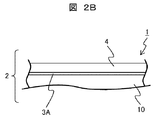
- 2A is a partial cross-sectional view taken along line A-A ′ in FIG. 2A.
- FIG. 1 is a schematic diagram showing a wind power generator of the present invention.
- a blade 1 of a wind power generator WP is attached to a rotary shaft 12 and generates power by a power generator (not shown) in a nacelle 13.
- Reference numeral 14 denotes a tower that supports the nacelle 13.
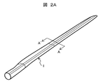
- FIG. 2A is a perspective view showing a blade 1 for a wind turbine generator according to Embodiment 1 of the present invention.
- 2B is a partial cross-sectional view taken along line A-A ′ in FIG. 2A.
- the blade surface layer 2 of the blade 1 includes a blade base material 10, a first conductive layer 3A as a functional layer, and a heat shrink film 4.
- a blade usually used for a wind power generator can be used.
- the blade base material 10 FRP having high strength and high rigidity is often used. In particular, in the case of large wind power generators, FRP blades are the mainstream.
- the blade substrate 10 is manufactured by a hand lay-up method using a polyester resin or an epoxy resin, a resin impregnation method, a vacuum impregnation method, an autoclave method, or the like.
- the blade 1 is protected by a heat shrink film 4 which is a heat shrinkable protective film.
- a heat shrink film 4 which is a heat shrinkable protective film.
- the term “film” includes a sheet. Therefore, a film is a broad concept including a long form, a roll form wound with a long product, a branch and leaf form, a thick film, and a thin film.
- the blade 1 When a heat-shrink film is used as the protective film, the blade 1 can be easily fixed by attaching the heat-shrink film 4 to the outer periphery of the blade base material 10 and heating it uniformly with a heating device. it can.
- the heat shrinkable film 4 when the heat shrinkable film 4 is deteriorated, the heat shrinkable film 4 can be easily exchanged by cutting the heat shrinkable film 4 so as not to damage the blade substrate 10 by any method. . Therefore, compared with the conventional protective film sticking method, the work man-hour at the time of heat shrink film 4 exchange can be reduced significantly.
- the material used for the heat-shrinkable film 4 is not particularly limited and can be appropriately selected depending on the purpose.
- examples thereof include polyolefins (for example, low density polyethylene, high density polyethylene, polypropylene, etc.), polyamides ( PA) (for example, nylon-6), polyacetals (POM), polyesters (for example, PET, PEN, PTT, PBT, PPT, PHT, PBN, PES, PBS, etc.), syndiotactic polystyrene (SPS) , Polyphenylene sulfides (PPS), polyether ether ketones (PEEK), liquid crystal polymers (LCP), fluororesins, isotactic polypropylene (isoPP), and the like.
- polyolefins for example, low density polyethylene, high density polyethylene, polypropylene, etc.
- PA for example, nylon-6
- POM polyacetals
- polyesters for example, PET, PEN, PTT, PBT, P
- polyolefins polyolefins, polyesters, syndiotactic polystyrene (SPS), and liquid crystal polymers (LCP) are preferable, and polyolefins and polyesters are more preferable from the viewpoints of durability, strength, production, and cost.
- SPS syndiotactic polystyrene
- LCP liquid crystal polymers
- the heat shrink film 4 may be used in a single layer state, or a film obtained by co-extrusion of two or more kinds of heat shrink films having different functions can be used.
- the heat-shrink film extruded separately can also be laminated
- the resin material constituting the blade base 10 is deteriorated by ultraviolet rays.
- a light-shielding function by imparting weather resistance to the heat-shrinkable film 4 or coloring it.
- various colors by applying various colors, it is possible to impart a decorative effect and the exchange thereof is easy.
- a technique for imparting light-shielding properties to the heat-shrinkable film for example, there is a method of laminating a light-shielding material containing titanium oxide on the heat-shrinkable film 4 containing an ultraviolet absorber.
- the heat shrink film 4 is fixed to the blade base material 10 by heat shrink. Therefore, compared with the conventional sticking method, even if an inclusion is present in the middle, there is almost no influence on the fixing force between them.
- a functional layer having various functions can be positively added between the shrink film 4 and the blade base material 10 by utilizing this feature.
- the functional layer disposed between the blade base material 10 and the heat shrink film 4 can be given various functions.
- As a countermeasure against lightning strikes on the blade there is a technology that uses a metal material at the tip of the blade as a lightning receptor and grounds with an electric wire along the main body of the windmill from the inside of the blade.
- ground faults will not be easy due to the construction of windmills in China. Therefore, in order to improve the lightning resistance of the blade, it is necessary to create a predetermined conductive member on the blade surface.
- the first conductive layer 3A made of a metal mesh is used.
- the first conductive layer 3A is disposed between the blade base material 10 and the heat shrinkable film 4, and the heat shrinkable film 4 is shrunk and attached so as to be integrally covered. It is possible to produce the blade 1 having a small work amount.
- the metal mesh is not particularly limited as long as it is used as a lightning protection sheet for an aircraft. Can be mentioned. By taking such a form, when the blade 1 is subjected to lightning, the metal mesh melts, so that the blade 1 can be discharged into the atmosphere.
- a heating wire is incorporated in the metal mesh layer of the first conductive layer 3A, and the blade is disposed between the blade base material 10 and the heat shrink film 4 so as to be integrally covered. Snow and ice adhesion can be prevented without applying one additional process.
- the first conductive layer 3A made of a wiring thin film is disposed at an arbitrary position on the outer surface of the blade, and the heat shrink film is contracted and adhered to cover the same.
- the damage of the macroscopic blade 1 can be monitored. That is, it is possible to detect that the blade is damaged when the conductive film is made conductive and the conductive film is not made conductive or when the resistance is changed.
- FIG. 3 shows Example 2 of the present invention, and the first conductive layer 3A and the second conductive layer 3B are disposed between the blade base material 10 and the heat shrink film 4.
- Each of the first conductive layer 3A and the second conductive layer 3B may have a different function, and two or more types or two or more layers may be provided. That is, the metal mesh, the heating wire, the wiring thin film, and the like described in Example 1 can be arbitrarily combined to form a composite layer.
- first conductive layer 3A and the second conductive layer 3B can be stretched over the entire blade 1, or each layer may be partially arranged. This is the same when the functional layer is a coal layer.
- the heat shrinkable film 4 and the blade base material 10 are not directly bonded to each other, even if the materials have different coefficients of thermal expansion, temperature fluctuations occur. It is possible to avoid the occurrence of delamination at the interface between the heat-shrinkable film 4, the blade base material 10, the first conductive layer 3A, and the second conductive layer 3B due to expansion and contraction.
- the time required for the peeling operation can be greatly shortened.
- FIG. 4 shows a third embodiment of the present invention, in which the blade base material 10 and the first conductive layer 3A disposed on the blade base material 10 are provided with the seams 5 at appropriate intervals.
- the shrink film 34 is integrally covered.
- the unit region of the heat shrink film 34 surrounded by the perforation 5 can be formed in, for example, a square or strip shape of any size, and can be exchanged for each unit.
- the heat-shrinkable film 4 only in the contaminated or damaged portion only needs to be partially peeled along the perforation 5 and replaced with a new heat-shrinkable film 4 for repair.
- the blade can be easily repaired on site.
- the repair heat shrink film 4 is covered with a substantially cylindrical heat shrink film 4 covering the peeled area on the blade base material 10 and fixed by heat shrink. Moreover, you may join the heat shrink film 4 for repair with an adhesive agent.
- FIG. 5 shows a fourth embodiment of the present invention.
- the blade surface layer 2 includes a blade base material 10, the first conductive layer 3A, and fine through holes 6 with respect to the thickness direction of the heat-shrinkable film. At least two or more layers of heat-shrinkable films 44 provided randomly are stacked and contracted and adhered to the blade substrate 10. The fine through hole 6 may also be formed by the perforation shown in the third embodiment.
- Example 4 it is possible to effectively remove the bubbles contained between the blade base material 10 or the first conductive layer 3A disposed on the blade base material 10 and the heat shrink film 44,
- the protective film construction work at the time of completion of the blade and the re-sticking work at the time of the replacement work in the repair can be avoided. Further, when such fine through holes 6 are continuously provided, they can be used as perforations, and the peeling work in the pasting is simplified.
- the form of the heat shrink film 44 for packaging the blade 1 is not particularly limited. It is provided in various forms according to the attaching method in which the attaching operation to a large blade is smoothly performed without man-hours. For example, it can be provided in the form of a roll around which a cylindrical, bag-like, or elongated strip-like protective film is wound.
- thermoshrinkable film 4 is shrunk and attached integrally with the blade base material 10 or the first conductive layer 3A disposed on the blade base material 10 by a heating device such as hot air or steam.
- FIG. 6 shows a fifth embodiment of the present invention
- the blade surface layer 2 is composed of a blade base material 10, a first conductive layer 3A, and a heat-shrinkable film 54 in the form of an elongated strip.
- the film 54 is wound around the outer periphery of the blade base material 10, and the end surfaces of the adjacent belt-shaped heat shrink films 54 are overlapped with each other on the film overlap surface 8.
- the heat-shrinkable film 54 has an elongated strip shape, and has an effect that the heat-shrinkable film can be easily manufactured and applied to the blade.
- the protection method according to the present invention is suitable for a blade for a wind power generator, but can also be applied to a nacelle cover for a wind power generator, a spinner cover, and the like, and its application range is not limited thereto.
Landscapes
- Engineering & Computer Science (AREA)
- Life Sciences & Earth Sciences (AREA)
- Sustainable Development (AREA)
- Sustainable Energy (AREA)
- Chemical & Material Sciences (AREA)
- Combustion & Propulsion (AREA)
- Mechanical Engineering (AREA)
- General Engineering & Computer Science (AREA)
- Wind Motors (AREA)
Description
本発明は、風力発電装置のブレード保護方法、及びこれにより保護されたブレード、およびかかるブレードを用いた風力発電装置に関する。
風力発電装置用の翼(以下、ブレードと記す)は、風を受けることによって回転し、その回転エネルギーを電気に変換する。風を受けて効率的に回転するためには、ブレードを軽量化して慣性力を低減することが重要である。また、風力発電装置のブレードは全長が60mを超えるものもあるため、ブレードの軽量化は、装置本体の小型化および軽量化につながる。さらに、ブレードが風から受ける力を効率的に回転運動に変換するため、ブレードの断面形状設計及びその形状の維持、表面の平滑性とその維持が求められる。
ブレードを構成する部材としては、従来はアルミニウム合金などの軽量な金属材料が用いられてきたが、近年では、さらなる軽量化の要求から、高強度かつ高剛性である繊維強化樹脂複合材(以下、FRPと記す)が用いられることが多い。特に、大型風力発電装置の場合、FRP製ブレードが主流となっている。
このような風力発電装置は、一度設置されると継続的に使用され続け、1年から2年毎に定期的に点検される程度である。一方、風力発電装置は強い風が長時間吹き続ける場所に設置されるのが一般的であり、周辺に高い建築物や木などがない海岸線に設置されることが多く、さらに発電効率を上げるため、海岸から離れた洋上での大型風力発電装置の建設数が増加している。このような海岸付近あるいは洋上では、太陽光による紫外線、風雨に加え、塩水の影響を受けたり、雹や鳥が衝突したりすることがある。また、ブレード長尺化にともない、落雷による損傷といった不具合も生じる。このほかにも、過酷な気候の土地に設置されることが多い。例えば、砂漠などでは、気温の寒暖の差が激しく強い太陽光を浴び砂嵐の影響を受けることもあり、火山地帯では腐食性ガスや火山灰の影響を受けることもある。
以上のようにブレードは厳しい環境下にさらされるため、長期間の使用により、損傷、変形、表面汚染、表面剥離といった不具合が起こる。このような不具合が生じると、外観不良により電力への変換効率が低下する。また、このような不具合を修復するためには、ブレードを取り外し、地上に下ろした状態で補修作業を行う必要があり、この間風力発電装置は発電することができない。そのため、補修は短時間で行わなければならない。
ブレード保護に関する背景技術として、特許文献1には、風力発電用ブレードの寿命を延長でき、かつ補修が容易な手段として、風力発電用ブレードの表面に、ブレードを保護するブレード用保護フィルムを貼付する方法が記載されている。この方法は、粘着剤層を備えたフィルム状のシートをブレード表面に貼付することにより、ブレードの外観維持や汚染防止による寿命を延長しようとするものである。このような粘着剤層を備えた保護フィルムは、FRP製ブレード表面部の汚染や損傷には一定の効果が得られる。
また、特許文献2には、風力発電機のブレード表面に、耐候性に優れ、かつ滑雪氷性と汚染除去性に優れた塗膜を形成できる表面塗布用塗料組成物による保護方法が記載されている。
しかしながら、特許文献1においては、保護フィルムを貼り替える際に人力で保護フィルムをブレードから剥がすことが容易でなく、さらに粘着力を上げるためにブレードの表面処理が必要となり多大なメンテナンス作業時間が必要となる。また、FRP製ブレード、フィルム状シート、および粘着剤層は熱膨張係数差があるため、温度変動により粘着剤層に繰り返しせん断力が発生し、保護フィルムの粘着力が低下する。さらに、ブレード表面と粘着剤層との間に異物が入り込むと局所的に粘着強度が低下し、風荷重や温度荷重の繰り返し作用により早期に保護フィルムがはく離する。
また、特許文献2において、ブレードの塗装作業は、ブレードの大型化に伴い飛躍的に塗装時間と乾燥時間が増加する。また、補修時においても多大な塗装時間を要し、その間発電装置を稼働させることができない。
本発明は、風力発電装置用のブレードに、保護フィルムの着脱が容易でありかつ耐雷性、耐候性、耐雪氷性等の付加機能を付与できる風力発電装置用のブレード保護方法を提供することを目的とする。
また、本発明は、保護フィルムの着脱が容易であり、耐雷性、耐候性、耐雪氷性を有する風力発電装置用のブレードおよびこれを用いた風力発電装置を提供することを目的とする。
本発明は、風力発電装置用のブレードと、ブレードを被覆する耐候性を持つ熱収縮フィルムと、ブレード外表面とフィルムとの間に設けた少なくとも1層の機能性層とを備え、熱収縮フィルムを加熱してブレードに収縮付着することによって、ブレードと前記機能性層とを熱収縮フィルムにより一体的に被覆することを特徴とする。
本発明の風力発電装置用ブレードの保護方法は、風力発電装置用のブレードと、ブレードを被覆する耐候性を持つ熱収縮フィルムと、ブレード外表面と熱収縮フィルムとの間に設けた少なくとも1層の機能性層とを備え、熱収縮フィルムを加熱してブレードに収縮付着することによって、ブレードと機能性層とを熱収縮フィルムにより一体的に被覆することにより、熱収縮フィルムからなる保護フィルムのブレードへの着脱が容易でありメンテナンス性に優れ、ブレードに耐雷性、耐候性、耐雪氷性等の付加機能を容易に付与することができる。また、本発明の風力発電装置用ブレードは、メンテナンス性に優れ、容易に耐雷性、耐候性、耐雪氷性を得ることができる。
さらに、本発明の保護方法によれば、保護フィルムのブレードへの着脱が容易であり、耐雷性、耐候性、耐雪氷性に優れる風力発電装置用のブレードを製造することができる。
以下、本発明の複数の実施例を複数の図を用いて説明する。図1は、本発明の風力発電装置を示す模式図である。図1において、風力発電装置WPのブレード1は回転軸12に取付けられ、ナセル13内の図示しない発電装置により発電を行う。14はナセル13を支持するタワーである。
図2Aは本発明の実施例1に係る風力発電装置用のブレード1を示す斜視図である。図2Bは、図2AにおけるA-A’部分断面図である。ブレード1のブレード表面層2は、図2Bに示すように、ブレード基材10と、機能性層としての第1導電層3Aと、熱収縮フィルム4から構成されている。本発明に係るブレードとして、風力発電機に通常使用されるブレードを使用することができる。ブレード基材10としては、高強度かつ高剛性であるFRPが用いられることが多い。特に、大型風力発電装置の場合には、FRP製ブレードが主流となっている。
ブレード基材10は、ポリエステル樹脂やエポキシ樹脂を用いたハンドレイアップ法、樹脂含浸法、真空含浸法、オートクレーブ法等によって製造される。
ブレード1は、熱収縮性をもつ保護フィルムである熱収縮フィルム4によって保護される。本発明においてフィルムという場合にはシートを包含する。したがって、フィルムとは、長尺形態、長尺品を巻き取ったロール形態、枝葉形態、厚いフィルム、薄いフィルムを含む広い概念である。
保護フィルムとして熱収縮フィルムを使用する場合は、ブレード1への装着は、熱収縮フィルム4をブレード基材10外周に装着して、加熱装置により均一に加熱することにより、容易に固定することができる。
また、熱収縮フィルム4の劣化時にこれを交換する際は、任意の方法でブレード基材10を傷つけないように熱収縮フィルム4を切断すれば、容易に熱収縮フィルム4を交換することができる。従って、従来の保護フィルム貼付方法と比較して、熱収縮フィルム4交換時の作業工数を大幅に低減することができる。
熱収縮フィルム4に用いられる材料としては、特段の制限はなく、目的に応じて適宜選択することができ、例えば、ポリオレフィン類(例えば、低密度ポリエチレン、高密度ポリエチレン、ポリプロピレンなど)、ポリアミド類(PA)(例えば、ナイロン-6など)、ポリアセタール類(POM)、ポリエステル類(例えば、PET、PEN、PTT、PBT、PPT、PHT、PBN、PES、PBSなど)、シンジオタクチック・ポリスチレン(SPS)、ポリフェニレンサルファイド類(PPS)、ポリエーテルエーテルケトン類(PEEK)、液晶ポリマー類(LCP)、フッ素樹脂、アイソタクティックポリプロピレン(isoPP)などが挙げられる。その中でも、耐久性、強度、製造およびコストの観点から、ポリオレフィン類、ポリエステル類、シンジオタクチック・ポリスチレン(SPS)、液晶ポリマー類(LCP)が好ましく、ポリオレフィン類、ポリエステル類がより好ましい。
これらのうち、2種以上のポリマーをブレンドしたり、共重合させたりして使用してもよい。また、熱収縮フィルム4は単一層の状態で用いてもよく、また、それぞれ機能が異なる2種類以上の熱収縮フィルムを共押し出し加工したものを用いることもできる。また、別々に押し出し加工した熱収縮フィルムを積層することもできる。
ブレード基材10を構成する樹脂材料は、紫外線により劣化することが知られている。ブレード基材10を紫外線から保護するため、熱収縮フィルム4に耐候性を付与したり、着色したりすることによって遮光機能を付加することができる。また、種々の着色を施すことにより、装飾効果も付与することが可能であり、その交換も容易である。熱収縮フィルムに遮光性を付与する技術として、例えば、紫外線吸収剤を含む熱収縮フィルム4に酸化チタンを含有する遮光性材料を積層する方法がある。
熱収縮フィルム4はブレード基材10に熱収縮により固定されている。従って、従来の貼付方法と比較して、中間に介在物が存在しても両者の固着力には殆ど影響を与えない。
従って、この特徴を利用して収縮フィルム4とブレード基材10の間に各種の機能を有する機能性層を積極的に付加することができる。
ブレード基材10と熱収縮フィルム4の間に配置する機能性層には、種々の機能を与えることが可能である。ブレードの落雷対策としてブレード先端に備えた金属材をライトニングレセプターとして、ブレード内部から風車本体に沿わせた電線で地絡させる技術があるが、風車の大型化に伴う電線延長による重量増や、洋上での風車建設により地絡が容易ではなくなるという課題がある。そのため、ブレードの耐雷性を向上させるため、ブレード表面に所定の導電部材を作りこむ必要があるが、FRPからなるブレード本体を追加工することは容易ではなく、また、それに伴う変更や補修も容易ではない。
これに対し金属メッシュからなる第1導電層3Aを用い、ブレード基材10と熱収縮フィルム4との間に配置し、熱収縮フィルム4を収縮付着せしめて一体に被覆することで、耐雷性を有するブレード1を少ない作業量で作製することができる。金属メッシュは、航空機の耐雷材シートとして用いられるようなものであれば特に限定されることはなく、銅、黄銅、アルミニウム、ニッケル、スチール、ステンレススチール等からなる金属線をメッシュ状にしたものが挙げられる。このような形態をとることで、ブレード1が被雷した際、金属メッシュが溶融するためブレード1から大気中に放電させることができる。
また、寒冷地に設置された風力発電装置においては、雪や氷がブレード1に付着し、風の抵抗値の増加により風車効率や発電効率が低下するという問題がある。このような雪氷付着を防ぐ手段として、ブレード1にヒーターなどの発熱体を組み込む手法が効果的であるが、部品の追加工や据付けとなどの作業量が多大となる。
この場合、実施例1の応用例として、第1導電層3Aの金属メッシュ層に発熱線を組み込み、ブレード基材10と熱収縮フィルム4との間に配置して一体に被覆することで、ブレード1の追加工を施すことなく雪氷付着を防止することができる。
また、風力発電装置の稼働時、および停止時には、雹、小石、および鳥等がブレード1に衝突することがあり、ブレード1の表面にき裂が生じたり、ブレード基材102が層間はく離を起こしたりすることがある。このような損傷を放置しておくと、風荷重によってブレード1が曲げモーメントを受けたときに、損傷部が圧縮荷重を受けて座屈する可能性がある。
このような損傷を検知するために、加速度センサをブレードに貼りつけ運転時のブレードの挙動変化を監視する技術や、光ファイバセンサ、ひずみセンサによりブレードの変形量を検知する技術がある。いずれの技術についても、局所的な変化について検知することができるといえるが、ブレード1のすべてに渡って巨視的に損傷の有無を判断することは容易ではない。
これに対して、実施例1の他の応用例として、配線薄膜からなる第1導電層3Aをブレード外表面における任意の位置に配置し、熱収縮フィルムを収縮付着せしめて一体に被覆することで、巨視的なブレード1の損傷をモニタリングすることができる。すなわち配線薄膜に導通を行い、導通しない場合或いはその抵抗変化により薄膜が断線する程度の損傷がブレードに生じていることを検知することができる。
図3は、本発明の実施例2を示したものであり、ブレード基材10と、熱収縮フィルム4との間に、第1導電層3Aと第2導電層3Bが配置される。第1導電層3A、第2導電層3Bはそれぞれが異なる機能を持っていてもよく、2種類以上あるいは2層以上設けてもよい。即ち、実施例1に挙げた金属メッシュ、発熱線、配線薄膜等を任意に組み合わせて複合層として形成する事ができる。
また、ブレード1全体にわたって第1導電層3A、第2導電層3Bを張り巡らせることもできるし、各層を部分的に配置してもよい。これは機能性層が炭層の場合も同様である。
このような熱収縮フィルム4と、ブレード基材10、第1導電層3A、第2導電層3Bとは、それぞれが直接接着されていないため、熱膨張係数が各々異なる材料であっても温度変動による膨張、収縮に起因する熱収縮フィルム4と、ブレード基材10と、第1導電層3A、第2導電層3Bの界面におけるはく離の発生を避けることができる。
さらに、ブレード基材10、第1導電層3A、第2導電層3Bを傷つけることなく、容易に、かつ完全に分離することができるため、剥離作業にかかる時間を大幅に短縮することができる。
図4は、本発明の実施例3を示したものであり、ブレード基材10と、ブレード基材10上に配置した第1導電層3Aとが、適当な間隔でシン目5を設けた熱収縮フィルム34によって一体に被覆されている。ミシン目5で囲まれる熱収縮フィルム34の単位領域は、例えば任意のサイズの正方形、または短冊形に形成する事ができ、この単位毎に交換することができる。
本実施例の効果としては、汚染または損傷を受けた部分のみの熱収縮フィルム4をミシン目5に沿って部分的に剥離し新しいリペア用の熱収縮フィルム4と貼り替えるだけでよいため、設置現場でもブレードの補修が容易となる。リペア用の熱収縮フィルム4は、剥離領域をカバーするほぼ円筒形熱収縮フィルム4をブレード基材10に被せて、熱収縮により固定する。またリペア用の熱収縮フィルム4を接着剤で接合しても良い。
図5は、本発明の実施例4を示したものであり、ブレード表面層2は、ブレード基材10と、第1導電層3Aと、熱収縮フィルムの厚さ方向に対して微細貫通孔6をランダムに設けた熱収縮フィルム44を少なくとも2層以上重ねて、ブレード基材10に収縮付着せしめた構成をとる。微細貫通孔6はまた、実施例3に示すミシン目で構成しても良い。
実施例4の効果としては、ブレード基材10、もしくはブレード基材10に配置した第1導電層3Aと、熱収縮フィルム44との間に含まれた気泡を効果的に除去することができ、ブレード完成時における保護フィルム施工作業や、補修における貼り替え作業時における貼り直し作業を回避することができる。また、このような微細貫通穴6を連続的に設けた場合には、これをミシン目としても利用することができ、貼り替えにおけるはく離作業が簡便となる。
本発明において、ブレード1を包装する熱収縮フィルム44の形態は、特に限定されない。大型のブレードへの貼付作業に工数をかけることなく、かつ平滑に貼り合わせる貼付方法に応じて、種々の形態で提供される。例えば、筒状、もしくは袋状、もしくは細長の帯状の保護フィルムを巻き付けたロール状で提供することができる。このような熱収縮フィルムを用いた包装手段として、例えば、筒状、もしくは袋状、もしくは細長帯状の保護フィルムを用いて、若干の余裕を持たせて予備的にブレード基材10を包装した後、熱風、もしくはスチーム等の加熱装置によって、熱収縮フィルム4をブレード基材10、もしくはブレード基材10に配置した第1導電層3Aと一体に収縮付着させる方法がある。
図6は、本発明の実施例5を示したものであり、ブレード表面層2は、ブレード基材10と、第1導電層3Aと、細長帯状の熱収縮フィルム54とから構成され、熱収縮フィルム54がブレード基材10の外周に巻き付けられて、隣り合う帯状の熱収縮フィルム54の端面同士がフィルム重なり面8で重なる構成をとる。
この場合は、熱収縮フィルム54は、細長帯状をなしており、熱収縮フィルムの製造およびブレードへの施工が容易であるという効果を有する。
本発明に係る保護方法は、風力発電装置用ブレードに好適であるが、風力発電装置用ナセルカバー、スピナーカバーなどにも応用することができ、その応用範囲がこれらに限定されるものではない。
1 ブレード
2 ブレード表面層
3A 第1導電層
3B 第2導電層
4、34、44、54 熱収縮フィルム
5 ミシン目
6 微細貫通孔
8 フィルム重なり面
10 ブレード基材
2 ブレード表面層
3A 第1導電層
3B 第2導電層
4、34、44、54 熱収縮フィルム
5 ミシン目
6 微細貫通孔
8 フィルム重なり面
10 ブレード基材
Claims (14)
- 風力発電装置用のブレードと、該ブレードを被覆する耐候性を持つ熱収縮フィルムと、該ブレード外表面と該熱収縮フィルムとの間に設けた少なくとも1層の機能性層とを備え、
前記熱収縮フィルムを加熱して前記ブレードに収縮付着することによって、前記ブレードと前記機能性層とを前記熱収縮フィルムにより一体的に被覆することを特徴とする風力発電装置用のブレード保護方法。 - 請求項1に記載の風力発電装置用のブレード保護方法において、前記機能性層が導電層からなることを特徴とする風力発電装置用のブレード保護方法。
- 請求項2に記載の風力発電装置用のブレード保護方法において、前記導電層が金属メッシュ層からなることを特徴とする風力発電装置用のブレード保護方法。
- 請求項2に記載の風力発電装置用のブレード保護方法において、前記導電層が発熱線を有することを特徴とする風力発電装置用のブレード保護方法。
- 請求項2に記載の風力発電装置用のブレード保護方法において、前記導電層が配線薄膜からなることを特徴とする風力発電装置用のブレード保護方法。
- 請求項1乃至5のいずれかに記載の風力発電装置用のブレード保護方法において、前記熱収縮フィルムに該熱収縮フィルムを部分的に前記ブレードから剥離するミシン目を任意の間隔で設けたことを特徴とする風力発電装置用のブレード保護方法。
- 請求項1乃至5のいずれかに記載の風力発電装置用のブレード保護方法において、前記熱収縮フィルムは少なくとも2層からなることを特徴とする風力発電装置用のブレード保護方法。
- 請求項7に記載の風力発電装置用のブレード保護方法において、前記熱収縮フィルムは微細な貫通孔が不規則に設けられた該熱収縮フィルムから構成されたことを特徴とする風力発電装置用のブレード保護方法。
- 請求項1乃至8のいずれかに記載の風力発電装置用のブレード保護方法において、前記熱収縮フィルムが前記ブレード外表面のうち少なくとも一部を被覆することを特徴とする風力発電装置用のブレード保護方法。
- 請求項1乃至8のいずれかに記載の風力発電装置用のブレード保護方法において、略円筒状に成形した前記熱収縮フィルムを、前記ブレードと該ブレードの外表面に配置した前記導通層とを包含するように配置し、前記熱収縮フィルムを収縮付着することによって、前記ブレードと前記導電層とを一体的に被覆することを特徴とする風力発電装置用のブレード保護方法。
- 請求項1乃至8のいずれかに記載の風力発電装置用のブレード保護方法において、帯状に成形加工された前記熱収縮フィルムを前記ブレードと前記導電層の上に順次貼り合わせ、前記熱収縮フィルムをその幅方向端面同士がフィルム重なり面で重なるように貼り合わせることを特徴とする風力発電装置用のブレード保護方法。
- 請求項1乃至8のいずれかに記載の風力発電装置用のブレード保護方法において、加熱装置によって前記熱収縮フィルムを加熱し、前記ブレードに収縮付着させたことを特徴とする風力発電装置用のブレード保護方法。
- 請求項1乃至12のいずれか1つに記載の風力発電装置用のブレード保護方法を用いて制作されたことを特徴とする風力発電装置用のブレード。
- 請求項13に記載の風力発電装置用のブレードを備えることを特徴とする風力発電装置。
Priority Applications (2)
| Application Number | Priority Date | Filing Date | Title |
|---|---|---|---|
| PCT/JP2012/071686 WO2014033832A1 (ja) | 2012-08-28 | 2012-08-28 | 風力発電用ブレードの保護方法およびブレード |
| JP2014532612A JP6005749B2 (ja) | 2012-08-28 | 2012-08-28 | 風力発電装置用のブレード保護方法 |
Applications Claiming Priority (1)
| Application Number | Priority Date | Filing Date | Title |
|---|---|---|---|
| PCT/JP2012/071686 WO2014033832A1 (ja) | 2012-08-28 | 2012-08-28 | 風力発電用ブレードの保護方法およびブレード |
Publications (1)
| Publication Number | Publication Date |
|---|---|
| WO2014033832A1 true WO2014033832A1 (ja) | 2014-03-06 |
Family
ID=50182683
Family Applications (1)
| Application Number | Title | Priority Date | Filing Date |
|---|---|---|---|
| PCT/JP2012/071686 Ceased WO2014033832A1 (ja) | 2012-08-28 | 2012-08-28 | 風力発電用ブレードの保護方法およびブレード |
Country Status (2)
| Country | Link |
|---|---|
| JP (1) | JP6005749B2 (ja) |
| WO (1) | WO2014033832A1 (ja) |
Cited By (6)
| Publication number | Priority date | Publication date | Assignee | Title |
|---|---|---|---|---|
| JP2015190400A (ja) * | 2014-03-28 | 2015-11-02 | 株式会社東芝 | 気流発生装置の取付治具、および、気流発生装置の取付方法 |
| CN108843486A (zh) * | 2018-07-30 | 2018-11-20 | 中科国风检测(天津)有限公司 | 一种风电叶片前缘防护系统及施工工艺 |
| CN112659599A (zh) * | 2020-11-05 | 2021-04-16 | 中国长江三峡集团有限公司 | 一种防除风机叶片覆冰的基于ptfe膜制备方法及应用 |
| CN112977837A (zh) * | 2019-12-12 | 2021-06-18 | 古德里奇公司 | 用于旋转叶片的防冰系统 |
| WO2021241385A1 (ja) * | 2020-05-25 | 2021-12-02 | 三菱重工業株式会社 | 風車翼、風車、及び、風車翼の補修方法 |
| JP2022538402A (ja) * | 2019-06-20 | 2022-09-02 | ギャラクティック コ.,エルエルシー | 一体型引抜成形複合プロファイルおよびその製造方法 |
Families Citing this family (1)
| Publication number | Priority date | Publication date | Assignee | Title |
|---|---|---|---|---|
| JP6655660B2 (ja) * | 2018-06-15 | 2020-02-26 | 三菱重工業株式会社 | 風車翼保護構造及びその形成方法 |
Citations (7)
| Publication number | Priority date | Publication date | Assignee | Title |
|---|---|---|---|---|
| JPS56151282A (en) * | 1980-04-23 | 1981-11-24 | Mitsubishi Electric Corp | Vertical-shaft type windmill |
| JPH048774U (ja) * | 1990-05-10 | 1992-01-27 | ||
| JP2009008040A (ja) * | 2007-06-29 | 2009-01-15 | Mecaro:Kk | マグナス型風力発電装置 |
| JP2009275536A (ja) * | 2008-05-13 | 2009-11-26 | Global Energy Co Ltd | 風車の羽根並びに風車 |
| JP2010096074A (ja) * | 2008-10-16 | 2010-04-30 | Global Energy Co Ltd | 風車の翼並びにその製造方法 |
| US20100264665A1 (en) * | 2009-04-17 | 2010-10-21 | 3M Innovative Properties Company | Lightning protection sheet with patterned discriminator |
| JP2010234989A (ja) * | 2009-03-31 | 2010-10-21 | Ikutoku Gakuen Kanagawa Koka Daigaku | 着氷防止構造を有する翼構造体 |
-
2012
- 2012-08-28 WO PCT/JP2012/071686 patent/WO2014033832A1/ja not_active Ceased
- 2012-08-28 JP JP2014532612A patent/JP6005749B2/ja not_active Expired - Fee Related
Patent Citations (7)
| Publication number | Priority date | Publication date | Assignee | Title |
|---|---|---|---|---|
| JPS56151282A (en) * | 1980-04-23 | 1981-11-24 | Mitsubishi Electric Corp | Vertical-shaft type windmill |
| JPH048774U (ja) * | 1990-05-10 | 1992-01-27 | ||
| JP2009008040A (ja) * | 2007-06-29 | 2009-01-15 | Mecaro:Kk | マグナス型風力発電装置 |
| JP2009275536A (ja) * | 2008-05-13 | 2009-11-26 | Global Energy Co Ltd | 風車の羽根並びに風車 |
| JP2010096074A (ja) * | 2008-10-16 | 2010-04-30 | Global Energy Co Ltd | 風車の翼並びにその製造方法 |
| JP2010234989A (ja) * | 2009-03-31 | 2010-10-21 | Ikutoku Gakuen Kanagawa Koka Daigaku | 着氷防止構造を有する翼構造体 |
| US20100264665A1 (en) * | 2009-04-17 | 2010-10-21 | 3M Innovative Properties Company | Lightning protection sheet with patterned discriminator |
Cited By (12)
| Publication number | Priority date | Publication date | Assignee | Title |
|---|---|---|---|---|
| JP2015190400A (ja) * | 2014-03-28 | 2015-11-02 | 株式会社東芝 | 気流発生装置の取付治具、および、気流発生装置の取付方法 |
| CN108843486A (zh) * | 2018-07-30 | 2018-11-20 | 中科国风检测(天津)有限公司 | 一种风电叶片前缘防护系统及施工工艺 |
| CN108843486B (zh) * | 2018-07-30 | 2023-10-13 | 中科国风检测(天津)有限公司 | 一种风电叶片前缘防护系统及施工工艺 |
| JP2022538402A (ja) * | 2019-06-20 | 2022-09-02 | ギャラクティック コ.,エルエルシー | 一体型引抜成形複合プロファイルおよびその製造方法 |
| CN112977837A (zh) * | 2019-12-12 | 2021-06-18 | 古德里奇公司 | 用于旋转叶片的防冰系统 |
| JP2021095911A (ja) * | 2019-12-12 | 2021-06-24 | グッドリッチ コーポレイション | 防除氷システム、回転ブレードアセンブリ、および風力タービン |
| WO2021241385A1 (ja) * | 2020-05-25 | 2021-12-02 | 三菱重工業株式会社 | 風車翼、風車、及び、風車翼の補修方法 |
| JP2021185309A (ja) * | 2020-05-25 | 2021-12-09 | 三菱重工業株式会社 | 風車翼、風車、及び、風車翼の補修方法 |
| TWI774387B (zh) * | 2020-05-25 | 2022-08-11 | 日商三菱重工業股份有限公司 | 風車翼、風車及風車翼的修補方法 |
| CN115552117A (zh) * | 2020-05-25 | 2022-12-30 | 三菱重工业株式会社 | 风车叶片、风车及风车叶片的修补方法 |
| JP7519811B2 (ja) | 2020-05-25 | 2024-07-22 | 三菱重工業株式会社 | 風車翼、風車、及び、風車翼の補修方法 |
| CN112659599A (zh) * | 2020-11-05 | 2021-04-16 | 中国长江三峡集团有限公司 | 一种防除风机叶片覆冰的基于ptfe膜制备方法及应用 |
Also Published As
| Publication number | Publication date |
|---|---|
| JP6005749B2 (ja) | 2016-10-12 |
| JPWO2014033832A1 (ja) | 2016-08-08 |
Similar Documents
| Publication | Publication Date | Title |
|---|---|---|
| JP6005749B2 (ja) | 風力発電装置用のブレード保護方法 | |
| EP2686546B1 (en) | Arrangement to improve the surface of a wind turbine blade | |
| JP5059249B2 (ja) | 翼体及び該翼体の積層保護シート | |
| US8506250B2 (en) | Wind turbine rotor blade with trailing edge extension and method of attachment | |
| RU2591369C2 (ru) | Лопатка ветровой турбины и способ изготовления такой лопатки | |
| US20170058863A1 (en) | Erosion resistant leading edge cap for a wind turbine rotor blade | |
| CN111164303B (zh) | 一种新材料在风力涡轮机的部件与装置中的应用及其方法 | |
| US10821696B2 (en) | Methods for manufacturing flatback airfoils for wind turbine rotor blades | |
| US20110097211A1 (en) | Wind turbine blade | |
| EP3724486B1 (en) | A wind tubine blade leading edge device and method of installing the leading edge device | |
| EP4204685A1 (en) | Method for repairing a lightning protection system of a wind turbine rotor blade and wind turbine rotor blade | |
| WO2013128682A1 (ja) | 繊維強化プラスチック発熱体および該発熱体を備えた風力発電装置 | |
| US20130101417A1 (en) | Wind turbine rotor blades with ultraviolet light-reflective substances | |
| CN114801397A (zh) | 用于修补外部受损部的快速修复补片及快速修复方法 | |
| CN201714588U (zh) | 风电叶片叶尖避雷装置保护套 | |
| AU2013351393A1 (en) | Method for processing a fiber-plastic composite of a rotor blade, semifinished product in the form of a built-up composite, and UV lamp for curing a UV-curable matrix material | |
| CN102374137B (zh) | 一种防结冰的风力发电机叶片的制备方法 | |
| JP2021525336A (ja) | 風力タービンブレードの前縁を修理する方法 | |
| CN210686193U (zh) | 防护装置和风力发电机组的叶片 | |
| Fan et al. | Flexible photovoltaic solar design | |
| CN111894791A (zh) | 叶片和风力发电机组 | |
| CN201421843Y (zh) | 太阳能电池背板用电气绝缘片 | |
| CN212223611U (zh) | 一种斜拉桥用抗结冰的拉索 | |
| WO2019197474A1 (en) | A covering for a wind turbine blade | |
| Ischtschuk et al. | Multi-functional Hybrid Material to Protect Rotor Blades |
Legal Events
| Date | Code | Title | Description |
|---|---|---|---|
| 121 | Ep: the epo has been informed by wipo that ep was designated in this application |
Ref document number: 12883895 Country of ref document: EP Kind code of ref document: A1 |
|
| ENP | Entry into the national phase |
Ref document number: 2014532612 Country of ref document: JP Kind code of ref document: A |
|
| NENP | Non-entry into the national phase |
Ref country code: DE |
|
| 122 | Ep: pct application non-entry in european phase |
Ref document number: 12883895 Country of ref document: EP Kind code of ref document: A1 |