WO2014030677A1 - レンズ鏡胴 - Google Patents
レンズ鏡胴 Download PDFInfo
- Publication number
- WO2014030677A1 WO2014030677A1 PCT/JP2013/072319 JP2013072319W WO2014030677A1 WO 2014030677 A1 WO2014030677 A1 WO 2014030677A1 JP 2013072319 W JP2013072319 W JP 2013072319W WO 2014030677 A1 WO2014030677 A1 WO 2014030677A1
- Authority
- WO
- WIPO (PCT)
- Prior art keywords
- lens frame
- lens
- optical axis
- lens barrel
- frame
- Prior art date
- Legal status (The legal status is an assumption and is not a legal conclusion. Google has not performed a legal analysis and makes no representation as to the accuracy of the status listed.)
- Ceased
Links
Images











Classifications
-
- G—PHYSICS
- G02—OPTICS
- G02B—OPTICAL ELEMENTS, SYSTEMS OR APPARATUS
- G02B7/00—Mountings, adjusting means, or light-tight connections, for optical elements
- G02B7/02—Mountings, adjusting means, or light-tight connections, for optical elements for lenses
-
- G—PHYSICS
- G02—OPTICS
- G02B—OPTICAL ELEMENTS, SYSTEMS OR APPARATUS
- G02B27/00—Optical systems or apparatus not provided for by any of the groups G02B1/00 - G02B26/00, G02B30/00
- G02B27/64—Imaging systems using optical elements for stabilisation of the lateral and angular position of the image
- G02B27/646—Imaging systems using optical elements for stabilisation of the lateral and angular position of the image compensating for small deviations, e.g. due to vibration or shake
-
- G—PHYSICS
- G03—PHOTOGRAPHY; CINEMATOGRAPHY; ANALOGOUS TECHNIQUES USING WAVES OTHER THAN OPTICAL WAVES; ELECTROGRAPHY; HOLOGRAPHY
- G03B—APPARATUS OR ARRANGEMENTS FOR TAKING PHOTOGRAPHS OR FOR PROJECTING OR VIEWING THEM; APPARATUS OR ARRANGEMENTS EMPLOYING ANALOGOUS TECHNIQUES USING WAVES OTHER THAN OPTICAL WAVES; ACCESSORIES THEREFOR
- G03B5/00—Adjustment of optical system relative to image or object surface other than for focusing
-
- G—PHYSICS
- G03—PHOTOGRAPHY; CINEMATOGRAPHY; ANALOGOUS TECHNIQUES USING WAVES OTHER THAN OPTICAL WAVES; ELECTROGRAPHY; HOLOGRAPHY
- G03B—APPARATUS OR ARRANGEMENTS FOR TAKING PHOTOGRAPHS OR FOR PROJECTING OR VIEWING THEM; APPARATUS OR ARRANGEMENTS EMPLOYING ANALOGOUS TECHNIQUES USING WAVES OTHER THAN OPTICAL WAVES; ACCESSORIES THEREFOR
- G03B2205/00—Adjustment of optical system relative to image or object surface other than for focusing
-
- G—PHYSICS
- G03—PHOTOGRAPHY; CINEMATOGRAPHY; ANALOGOUS TECHNIQUES USING WAVES OTHER THAN OPTICAL WAVES; ELECTROGRAPHY; HOLOGRAPHY
- G03B—APPARATUS OR ARRANGEMENTS FOR TAKING PHOTOGRAPHS OR FOR PROJECTING OR VIEWING THEM; APPARATUS OR ARRANGEMENTS EMPLOYING ANALOGOUS TECHNIQUES USING WAVES OTHER THAN OPTICAL WAVES; ACCESSORIES THEREFOR
- G03B2205/00—Adjustment of optical system relative to image or object surface other than for focusing
- G03B2205/0007—Movement of one or more optical elements for control of motion blur
- G03B2205/0015—Movement of one or more optical elements for control of motion blur by displacing one or more optical elements normal to the optical axis
Definitions
- the present invention relates to a lens barrel having a camera shake correction mechanism.
- a conventional camera shake correction mechanism includes a fixed portion fixed to a lens barrel, a first guide shaft that is provided on the fixed portion and supports a support frame, a support frame that supports the lens frame via a second guide shaft, and correction A lens frame for holding the lens for use.
- the fixed portion fixed to the lens barrel supports the support frame so that it can be guided in a predetermined direction in a plane orthogonal to the optical axis by the first guide shaft.
- the support frame supports the lens frame by the second guide shaft so that the lens frame can be guided in a direction orthogonal to the predetermined direction.
- a first guide mechanism for guiding the support frame in the first direction is provided in the fixed portion, and a second guide mechanism for guiding the lens frame in the second direction is provided thereon. That is, in this camera shake correction mechanism, the lens frame is movable within a plane orthogonal to the optical axis (see, for example, Patent Document 1).
- the camera shake correction mechanism includes a fixed portion fixed to the lens barrel, a lens frame holding the correction lens, and a ball sandwiched between the fixed portion and the lens frame.
- a spring that urges the ball in the direction of holding the ball is stretched between the fixed portion and the lens frame.
- the lens frame is placed so as to be movable with respect to the fixed portion via the ball by the bias of the spring. That is, according to the above configuration, rotation around the optical axis in the lens frame is suppressed, and the lens frame can move in a plane orthogonal to the optical axis (see, for example, Patent Document 2).
- the camera shake correction mechanism in another example has both a guide mechanism for performing the above-described camera shake correction and a retraction mechanism.
- the retracting mechanism retracts a part of the lens to the outside of the optical axis when collapsed to reduce the thickness when retracted.
- the lens frame that supports the correction lens is rotatably supported by the vibration frame used for camera shake correction.
- the retraction mechanism rotates the correction lens with respect to the vibration frame and retracts it outside the optical axis (for example, Patent Document 3).
- a voice coil motor (VCM) is often used as an actuator used for these camera shake corrections.
- the voice coil motor has a moving frame supported so as to be movable in a plane perpendicular to the optical axis with respect to the fixed portion.
- a permanent magnet is fixed to the moving frame. Further, the hall element and the coil are fixed to the fixed portion so as to face the permanent magnet.
- the Hall element When performing camera shake correction using the camera shake correction mechanism, the Hall element outputs a signal corresponding to the change in the magnetic field generated by the permanent magnet, and detects the position of the moving frame.
- the lens barrel described in Patent Document 2 has a structure that prevents rotation of the lens frame in a plane orthogonal to the optical axis depending on the balance of biasing by the spring. Therefore, since the rotation of the lens frame cannot be completely prevented, a deviation occurs between the lens position and the sensor output for measuring the lens position. As a result, there is a problem that the camera shake correction performance is deteriorated.
- the arrangement of the springs for maintaining the balance of clamping by biasing in a predetermined state may be a restriction on the layout in the camera shake correction mechanism. As a result, there has been a problem that the camera shake correction mechanism and the lens barrel are increased in size.
- camera shake correction is performed by moving the entire vibration frame while rotatably supporting the lens frame.
- an object to be moved at the time of camera shake correction is increased in size, and the mass of the object is increased. These cause the size of the actuator that drives the object and the deterioration of the characteristics.
- the vibration frame provided with the actuator maintains its position even when retracted. Therefore, it becomes a hindrance when trying to make the lens barrel thin when retracted.
- the present invention solves the above-described problems, and an object of the present invention is to provide a lens barrel having a camera shake correction mechanism capable of reducing cost while reducing size.
- the lens barrel according to claim 1 is a lens barrel having a camera shake correction mechanism that moves a correction lens in a plane orthogonal to the optical axis of the photographing optical system.
- the camera shake correction mechanism includes a first axis fixed in parallel to the optical axis, a link member provided to be rotatable about the first axis, the link member, A second axis parallel to the axis; and a lens frame provided so as to be rotatable about the second axis and holding the correction lens.
- the lens barrel according to a second aspect of the present invention is the lens barrel according to the first aspect of the invention, wherein the amount of rotation of the lens frame when retracted is larger than that during camera shake correction, so that the correction lens is It is retracted from the optical axis.
- the first restriction portion that restricts the rotation amount of the link member, the second restriction portion that restricts the rotation amount of the lens frame, It is characterized by having.
- the second restricting portion when the rotation of the link member is restricted at one end of the first restricting portion, the second restricting portion is provided on the lens frame.
- the other end of the first restricting portion restricts the rotation of the link member, and the amount of rotation of the lens frame at the time of retracting is larger than that during camera shake correction.
- the correction lens is retracted from the optical axis at the time of photographing.
- the lens frame has a driven portion formed around a sleeve through which the second shaft passes, and the driven portion is retracted.
- the engaging member is engaged, the amount of rotation of the lens frame when retracted is larger than that during camera shake correction.
- the first urging force is applied to urge the lens frame in a returning direction in response to the rotation of the lens frame when retracted. It has the means.
- the first urging means does not urge the lens frame at the time of camera shake correction, and the rotation amount of the lens frame is a camera shake. It is characterized by energizing when it becomes larger than the time of correction.
- a lens barrel according to an eighth aspect of the invention is characterized in that, in the invention according to any one of the first to seventh aspects, the lens barrel includes a second urging means for urging the lens frame in the optical axis direction.
- a lens barrel according to a ninth aspect is the lens barrel according to any one of the first to eighth aspects, wherein the lens barrel is disposed on either the lens frame or a facing member facing the lens frame in a shooting state. It has a magnet, the coil arrange
- a lens barrel according to claim 10 is the lens barrel according to claim 3, wherein the lens is disposed on one of the lens frame or a facing member facing the lens frame in a shooting state, and the lens.
- a coil disposed on the other side of the frame or the opposing member, and a hall element disposed on the other side of the lens frame or the opposing member, and rotating the link member at at least one end of the first restricting portion. The movement is restricted, and the output of the Hall element is calibrated by bringing the lens frame into contact with a second restriction part.
- a lens barrel according to an eleventh aspect of the present invention is the lens barrel according to any one of the first to tenth aspects, further comprising a shutter unit that is disposed on the optical axis and includes a notch at a part of an outer edge thereof. And the first axis and the second axis are respectively arranged so as to penetrate the notch in a direction parallel to the optical axis.
- the lens barrel according to a twelfth aspect of the invention is characterized in that, in the invention according to the eleventh aspect, the correction lens is disposed immediately before or after the shutter unit.
- the lens barrel includes a camera shake correction mechanism that moves a correction lens in a plane orthogonal to the optical axis of the photographing optical system.
- a lens frame that holds the correction lens and a facing member that faces the lens frame, and one of the lens frame and the facing member is provided with a magnet, and the other is a signal corresponding to the position of the coil and the magnet.
- the lens barrel is retracted, the lens frame is withdrawn from the optical axis while holding the magnet or the coil and the position detecting means, and in the optical axis direction with respect to the opposing member. It is also moved to.
- the lens barrel according to a fourteenth aspect is the invention according to the thirteenth aspect, in which the lens and the magnet and the coil or the position detecting unit are arranged so that the optical axis is moved after the lens frame moves in the optical axis direction. It is located so that it may become a position including the same plane orthogonal to.
- the lens frame is disposed on the image plane side with respect to the facing member, and the lens frame is used as the facing member when retracted. On the other hand, it is moved to the subject side.
- a lens barrel according to a sixteenth aspect is the invention according to any one of the thirteenth to fifteenth aspects, wherein a first axis disposed on the frame holding member and fixed in parallel with the optical axis, and the first axis A link member rotatably provided around the axis, and a second axis parallel to the optical axis provided on the link member, the lens frame having the second axis as an axis It is provided to be rotatable.
- the lens barrel according to claim 17 is the lens barrel according to any one of claims 13 to 16, wherein when the lens barrel is retracted, the rotation amount of the lens frame is larger than that during camera shake correction. The lens is retracted from the optical axis at the time of photographing.
- the lens barrel of the present invention it is possible to provide a lens barrel having a camera shake correction mechanism that can be reduced in size and cost.
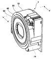
- FIG. 3 is a perspective view of a lens barrel in a photographing enabled state (wide end).
- FIG. 3 is a perspective view of a lens barrel in a photographing enabled state (tele end).
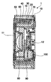
- FIG. 5 is a sectional view taken along line VV in FIG. 2.
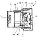
- FIG. 6 is a sectional view taken along line VI-VI in FIG. 3.
- FIG. 7 is a sectional view taken along line VII-VII in FIG. 4.
- the figure which shows the structure of a 1st biasing means The perspective view when a part of fixed cylinder is seen from diagonally forward.
- FIG. 1 is a view of the second group holding cylinder 70 constituting the lens barrel 1 when viewed from the rear (image sensor side) in the optical axis A.
- FIG. 1 is a view of the second group holding cylinder 70 constituting the lens barrel 1 when viewed from the rear (image sensor side) in the optical axis A.
- the direction corresponding to 3 o'clock when viewed from the rear in the optical axis A is the right direction. May be described.
- a direction corresponding to 6 o'clock may be described as a downward direction
- a direction corresponding to 9 o'clock as a left direction
- a direction corresponding to 12 o'clock as an upward direction.
- the left-right direction may be described as the X direction
- the up-down direction may be described as the Y direction.
- the imaging target side may be described as the front, the imaging element side as the rear, and the optical axis direction as the front-rear direction.
- FIG. 2 is a perspective view of the lens barrel 1 when retracted (not photographed).
- FIG. 3 is a perspective view of the lens barrel 1 in the wide state, which is one of the photographable states.
- FIG. 4 is a perspective view of the lens barrel 1 during telephoto, which is one of the photographable states.
- FIG. 5 is a cross-sectional view taken along line VV in FIG. 6 is a cross-sectional view taken along line VI-VI in FIG. 7 is a cross-sectional view taken along line VII-VII in FIG.
- the lens barrel 1 includes a fixed barrel 10, a rectilinear barrel A20, a rotary barrel A30, a rectilinear barrel B40, a front barrel 50, a rotary barrel B60, a second group holding barrel 70, a shutter unit 80, A lens frame 90 and a photographing optical system are included.
- the photographing optical system includes a first optical element 11, a second optical element 12, and a correction lens 100 (see FIGS. 1, 5 to 7).
- the correction lens group may be simply referred to as a correction lens 100.
- a zoom photographing optical system composed of three groups will be described, but the present embodiment is not limited to this example.
- the correction lens 100 is displaced in the X direction and the Y direction within a plane orthogonal to the optical axis of the photographing optical system during photographing. Due to this displacement, image blur of the subject image due to camera shake is reduced.
- the fixed cylinder 10 is provided with an image sensor fixing portion, a second optical element 12, and an output gear 14 (see FIGS. 2 to 4).
- the output gear 14 is rotated by a motor (not shown).
- the image sensor fixing portion is a flat plate portion provided at the rear end portion in the optical axis direction of the lens barrel.
- a CCD (Charge Coupled Device) type image sensor, a C-MOS (Complementary Metal Oxide Semiconductor) type image sensor, or the like is used as the imaging element.
- the image sensor converts a subject image formed by the photographing optical system into an electrical signal.
- the second optical element is disposed behind the first optical element in the optical axis.
- the output gear 14 rotates the rotary cylinder A30.
- first guide for guiding the rectilinear cylinder A20 in the optical axis direction and a first cam (not shown) for moving the rotary cylinder A30 in the optical axis direction.
- the rectilinear cylinder A20 is moved in the optical axis direction integrally with the rotary cylinder A30 by being coupled to the rotary cylinder A30 and a bayonet.
- the rectilinear cylinder A20 is guided in the optical axis direction by the first guide.
- On the inner surface of the rectilinear cylinder A20 there are a second guide (not shown) for guiding the rectilinear cylinder B40 in the optical axis direction and a second cam (not shown) for moving the rotary cylinder B60 in the optical axis direction.
- the rotary cylinder A30 has a drive gear 13 at its rear end.
- the drive gear 13 is meshed with the output gear 14.
- the rotating cylinder A30 is moved in the optical axis direction by the first cam while rotating as the drive gear 13 is rotated.
- a transmission key (not shown) for transmitting the rotational force to the rotary cylinder B60 and a through hole (not shown) through which the cam pin of the rotary cylinder B60 passes are provided on the inner surface of the rotary cylinder A30.
- the rectilinear cylinder B40 is moved in the optical axis direction integrally with the rotating cylinder B60 by being bayonet-coupled with the rotating cylinder B60.
- the rectilinear cylinder B40 is guided in the optical axis direction by the second guide.
- a third guide (not shown) for guiding the front cylinder 50 in the optical axis direction and a fourth guide (not shown) for guiding the second group holding cylinder 70 in the optical axis direction. And have.
- the third guide and the fourth guide are provided integrally.
- the front tube 50 is guided in the optical axis direction by the third guide.
- the front cylinder 50 is moved in the optical axis direction by a third cam (not shown) of the rotary cylinder B60.
- the first optical element 11 is fixed to the front tube 50.
- Rotary cylinder B60 By transmitting the rotation of the rotary cylinder A30 to the rotary cylinder B60, the rotary cylinder B60 is moved in the optical axis direction by the second cam while rotating.
- a third cam for moving the front cylinder 50 straight in the optical axis direction is provided on the outer surface of the rotary cylinder B60, and a second cam for moving the second group holding cylinder 70 straight in the optical axis direction on the inner surface of the rotary cylinder B60.
- Four cams (not shown) are provided.
- FIG. 8 is a perspective view of the shutter unit as viewed obliquely from the front.
- FIG. 9 is a perspective view of the second group holding cylinder as viewed obliquely from the rear.
- FIG. 10 is a perspective view of the lens frame when viewed obliquely from the rear.
- FIG. 11 is a perspective view of the second group holding cylinder as viewed obliquely from the front.
- the second group holding cylinder 70 includes a shutter unit 80, a lens frame 90, a first shaft 111, a second shaft 112, a link member 113, and a first biasing force.
- Means 200 are provided.
- the second group holding cylinder 70 has a cylinder axis arranged along the optical axis, a second restricting portion 712, and a pair of flanges 71.
- the pair of flanges 71 includes a front end portion of the second group holding cylinder 70 at the front position of the shutter unit 80 in the optical axis direction and a second group holding cylinder at the rear position of the shutter unit 80. 70 at the rear end.
- the distance between the pair of front and rear flanges 71 in the optical axis direction has a sufficient length in the optical axis direction.
- the flange 71 on the front end side is provided in the range from approximately 7 o'clock to approximately 9 o'clock along the inner periphery of the second group holding cylinder 70.
- a first restricting portion 711 that is a hole for restricting the amount of rotation is provided at the approximately 8 o'clock position of the flange 71 on the front end side. An end portion of the second shaft 112 described later is inserted into the first restricting portion 711. With this configuration, the amount of rotation of the second shaft 112 is restricted, and the amount of rotation of the lens frame 90 in the substantially left-right direction is limited. That is, the amount of rotation of the correction lens 100 at the time of camera shake correction is restricted within a limited range (see FIGS. 17 and 18).
- the second restricting portion 712 is provided at the approximately 12:00 position along the inner periphery of the second group holding cylinder 70.
- the second restricting portion 712 includes an upper groove wall 713, a lower groove wall 714, and a left groove wall 715.
- the right end of the second restricting portion 712 is opened.
- a regulated portion 91 provided on the lens frame 90 is inserted into the second regulating portion 712. Further, when the second shaft 112 abuts on the left end of the first restricting portion 711, movement in the substantially vertical direction due to the rotation of the lens frame 90 is restricted. With this configuration, the amount of rotation of the correction lens 100 at the time of adjustment is restricted within a limited range.
- the relationship between the regulated part 91 and the second regulating part 712 will be described later.
- the lens barrel 1 When the lens barrel 1 is retracted, when the correction lens 100 is retracted from the above limit range, the lens frame is in a state where the second shaft 112 is in contact with the right end of the first restricting portion 711. 90 is rotated. As a result, the regulated portion 91 is detached from the open portion at the right end of the second regulating portion 712. Further, as shown in FIGS. 1 and 9, the second group holding cylinder 70 passes the correction lens 100 and its peripheral portion between about 5 o'clock and about 7 o'clock with about 6 o'clock as the center. Passage 72 is provided. When the regulated portion 91 is removed by the passage port 72 and the lens frame 90 and the correction lens 100 are further rotated, the correction lens 100 is retracted to a position of approximately 6 o'clock from the optical axis.
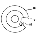
- FIG. 12 is a front view of the shutter unit 80 as viewed from the front.
- the shutter unit 80 is fixed in the second group holding cylinder 70. As shown in FIG.
- the shutter unit 80 (see FIG. 8) is disposed in the vicinity of the front of the correction lens 100.
- the shutter unit 80 includes a notch 81 at a part of the outer edge.
- the notch 81 is provided between approximately 3 o'clock and approximately 5 o'clock in FIG. 12 (approximately 7 o'clock to approximately 9 o'clock in FIG. 1).
- the first shaft 111, the second shaft 112, and the link member 113 are disposed in the notch 81. These are used when the camera shake correction mechanism 110 and the correction lens 100 are retracted from the optical axis. Even if the camera shake correction mechanism 110 and the retracting mechanism are provided by the notch 81, it is possible to suppress an increase in the diameter of the second group holding cylinder 70. Further, the first shaft 111 and the second shaft 112 can be disposed through the front and back of the shutter unit 80. With this configuration, the axial length can be made sufficiently long. In addition, the inclination of the lens frame 90 with respect to the optical axis can be suppressed. Further, the mounting accuracy of the lens frame 90 can be increased. The same effect can be obtained even when the shutter unit 80 is disposed at a position near the rear of the correction lens 100.
- a light shielding means for shielding the notch 81 is provided. Thereby, light leakage can be prevented.
- An example of the light shielding means is the flange 71 described above.
- the flange 71 is disposed forward and backward in the optical axis direction with the notch 81 interposed therebetween. That is, the flange 71 is configured so that light does not leak from the notch 81 or light is not inserted into the notch 81.
- the flange 71 has a function as a light shielding means, and further has a function of supporting the first shaft 111 and the like as will be described later. Also from this point, it is possible to reduce the size and the cost.
- the rotating cylinder B60 is rotated and moved forward along the optical axis direction by the second cam of the rectilinear cylinder A20.
- the rectilinear cylinder B40 is guided by the second guide of the rectilinear cylinder A20, and is moved forward along the optical axis direction together with the rotating cylinder B60 without rotating.
- the state shown in FIG. 3 and FIG. 6 is a photographing enabled state and shows a wide end state.
- the lens frame 90 is largely rotated about the second axis 112, and the correction lens 100 returns to the widened optical axis.
- the lens frame 90 is rotated about the first axis 111 and / or the second axis 112, so that the correction lens 100 can be moved to perform camera shake correction.
- the second group holding cylinder 70 is guided by the fourth guide of the rectilinear cylinder B40 and is moved forward along the optical axis direction by the fourth cam of the rotary cylinder B60.
- the lens frame 90 is attached to the lens frame 90 at each desired position from the photographing enabled state (wide end) shown in FIGS. 3 and 6 to the photographing ready state (tele end) shown in FIGS.
- the correction lens 100 held by the lens frame 90 is moved. With this operation, camera shake correction is performed.
- the rotating cylinder A30 is moved backward along the optical axis direction by the first cam of the fixed cylinder 10 while rotating.
- the rectilinear cylinder A20 is guided by the first guide of the fixed cylinder 10, and is moved in the optical axis direction together with the rotating cylinder A30 without rotating.
- the second group holding cylinder 70 is guided by the fourth guide of the rectilinear cylinder B40 and is moved rearward along the optical axis direction by the fourth cam of the rotating cylinder B60 (FIGS. 3 and FIG. 3). 6).
- the rotating cylinder B60 When the rotating cylinder B60 is rotated, the rotating cylinder B60 is moved rearward along the optical axis direction by the second cam of the rectilinear cylinder A20.
- the rectilinear cylinder B40 is guided by the second guide of the rectilinear cylinder A20, and is moved in the optical axis direction together with the rotating cylinder B60 without rotating.
- the first optical element 11 and the second optical element in the optical axis direction are moved when the front cylinder 50 is largely moved rearward with respect to the fixed cylinder 10 and approaches the fixed cylinder 10.
- the gap between the elements 12 is narrowed.
- the lens frame 90 is rotated more than the time of camera shake correction with the second shaft 112 as an axis, so that the correction lens 100 is moved to the optical axis. Evacuated outside. With this configuration, it is possible to reduce the thickness of the lens barrel 1 when retracted.
- FIG. 13 is a perspective view of the lens frame 90 when viewed obliquely from the front.
- the camera shake correction mechanism 110 includes a first shaft 111, a second shaft 112, a link member 113, and a lens frame 90.
- the first shaft 111 is fixed at a substantially 9 o'clock position of the flange 71.
- the length of the first axis 111 is spanned between the pair of front and rear flanges 71, has a sufficient length, and the inclination of the first axis 111 with respect to the optical axis is kept small.
- the first axis 111 may be an axis that is fixed with respect to the optical axis and substantially parallel to the optical axis.
- “fixed with respect to the optical axis” indicates that the object does not move in a plane perpendicular to the optical axis.
- the link member 113 is pivotally supported so as to be rotatable about the first shaft 111.
- the link member 113 is disposed along the inner periphery of the second group holding cylinder 70.
- the link member 113 is disposed in a section from approximately 7 o'clock to approximately 9 o'clock. This section corresponds to a section in which the notch 81 of the shutter unit 80 is provided (see FIGS. 1 and 12).
- the link member 113 With the second group holding cylinder 70 and the cutout portion 81, the link member 113 can be arranged with high space efficiency.
- the link member 113 is disposed so as to be fitted between the pair of front and rear flanges 71 in the optical axis direction.
- the distance between the pair of front and rear flanges 71 is sufficiently long because it is disposed across the front and back of the shutter unit 80 through the notch 81 in the optical axis direction.
- the link member 113 fitted in the gap is also sufficiently long in the optical axis direction. According to this configuration, the tilting of the first shaft 111 and the link member 113 with respect to the optical axis can be suppressed.
- the inclination of the link member 113 can be kept small. Thereby, the attachment accuracy of the link member 113 can be improved. As a result, the mounting accuracy of the lens frame 90 can be increased.
- FIG. 14 is a view when the link member 113 is cut along a plane orthogonal to the optical axis.
- FIG. 15 is a perspective view of the lens frame and the like in a photographing enabled state.
- FIG. 16 is a perspective view when the lens frame is retracted out of the optical axis.
- the other end portion of the link member 113 has a convex portion 114 and a concave portion 115 whose distance from the one end portion is shorter than the convex portion 114.
- the convex portion 114 is provided so as to sandwich the concave portion 115 from the front edge portion to the rear edge portion (see FIG. 15).
- the opening width of the recess 115 may be made sufficiently long in the optical axis direction.
- the second shaft 112 is provided at the other end of the link member 113.
- shaft 112 should just be provided in the position different in the link member 113 from the position in which the 1st axis
- the second axis 112 is an axis parallel to the optical axis.
- the second shaft 112 is configured to have a sufficient guide length so as to be bridged between the convex portion 114 on the front edge side and the convex portion 114 on the rear edge side. It may be.
- the inclination of the second axis 112 with respect to the optical axis can be kept small.
- the front end portion and the rear end portion of the second shaft 112 pass through the convex portion 114 on the front edge portion side and the convex portion 114 on the rear edge portion side, respectively (see FIG. 15).
- the front end portion and the rear end portion of the second shaft 112 are inserted into a first restricting portion 711 that is a hole for limiting the rotation amount of the link member 113.
- a first restricting portion 711 that is a hole for limiting the rotation amount of the link member 113.
- the lens frame 90 holds the correction lens 100. As shown in FIGS. 15 and 16, the lens frame 90 is fitted at the base end portion of the link member 113 on the second shaft 112 side, the second shaft 112 passes therethrough, and the second shaft 112 is used as an axis. It can be turned.
- the base end portion of the lens frame 90 is sufficiently long in the optical axis direction, the inclination of the base end portion of the lens frame 90 is suppressed to be small with respect to the second axis 112 (relative to the plane orthogonal to the second axis 112). Is possible. Thereby, the mounting accuracy of the lens frame 90 can be increased.
- the lens frame 90 is provided with a regulated portion 91, a locking portion 92 (see FIG. 20), a contact portion 93, and a pushed portion 94.
- the restricted portion 91 is provided at a position of the lens frame 90 at approximately 12:00.
- the restricted portion 91 is located between the upper groove wall 713 and the lower groove wall 714 of the second restricting portion 712 in the photographing enabled state.
- the relationship between the size of the restricted portion 91 and the vertical width of the second restricting portion 712 (the interval between the upper groove wall 713 and the lower groove wall 714, that is, the width in the Y direction) is appropriately set.
- a range in which the lens frame 90 can be rotated in the Y direction during camera shake correction is determined. That is, a range in which the correction lens 100 can be rotated in the vertical direction (Y direction) is determined.
- the locking portion 92 and the contact portion 93 are disposed around the second shaft 112 (see FIGS. 14, 20, and 21). Details of the locking portion 92 and the contact portion 93 will be described later.
- camera shake correction can be performed.
- the lens frame 90 is rotated about the first axis 111 and / or the second axis 112.
- the correction lens 100 held by the lens frame 90 is moved within the limited range of the surface orthogonal to the optical axis.
- the structure for that can be realized by the same configuration using the first shaft 111, the second shaft 112, and the link member 113. Therefore, it is possible to reduce the size and the cost with a simple configuration. Furthermore, the configuration in which the first shaft 111 and the second shaft 112 are rotated is less affected by friction than the configuration in which the shaft is arranged on a plane orthogonal to the optical axis and is slid as a guide. Therefore, the camera shake correction performance can be improved.
- the lens frame 90 when “the lens frame 90 is rotated about the first axis 111 and / or the second axis 112” is described, (1) rotating the lens frame 90 around the first shaft 111 integrally with the link member 113; (2) Rotating the lens frame 90 about the second shaft 112 without rotating the link member 113; (3) rotating the link member 113 about the first shaft 111 and rotating the lens frame 90 about the second shaft 112; Indicates. Further, the mode is different between the case where “the rotation of the lens frame 90” is regarded as the rotation around the axis and the case where it is regarded as the movement of the lens frame 90 in the camera shake correction. That is, in the camera shake correction, the lens frame 90 and the correction lens 100 are slightly moved within the limit range. Therefore, the movement of the correction lens 100 is effectively regarded as a linear minute movement.
- FIG. 1 is a diagram showing the lens frame 90 moved to the left end position.
- FIG. 17 is a diagram showing the lens frame 90 moved to the right end position.
- FIG. 18 is a diagram showing the lens frame 90 moved to the upper end position.
- FIG. 19 shows the lens frame 90 moved to the lower end position.
- the “restricted range” refers to a range in which the lens frame 90 and the correction lens 100 can move during camera shake correction.
- the position detection unit 300 includes a magnet 301 and a hall element 302.
- the magnets 301 are arranged at the 9 o'clock position and the 12 o'clock position of the lens frame 90, respectively.
- the Hall element 302 detects the position of the lens frame 90 in the X direction and the Y direction orthogonal to each other on a plane orthogonal to the optical axis. By detecting the position of the lens frame 90 using the magnet 301 and the Hall element 302, the correction lens 100 can be controlled with high accuracy and the configuration is simple.
- the Hall element 302 may be disposed in the second group holding cylinder 70.
- the position information of the lens frame 90 detected by the Hall element 302 may be different from the actual position information of the lens frame 90.
- the detected position information is calibrated based on predetermined position information of the lens frame 90.
- the output when the lens frame 90 is positioned at both ends of the first restricting portion and the second restricting portion is detected, and the center thereof is set as the center position of the lens frame 90.
- the position information is calibrated from the relationship between the amount of movement between both ends obtained in advance and the output. Note that the configuration of the position information is not limited to the embodiment.
- the calibration of the position information of the lens frame 90 can improve the performance of camera shake correction. This calibration is performed by a control circuit (not shown) for correcting camera shake.
- a magnet 301 and a coil 303 are provided.
- the coil 303 is disposed on the outer surface of the shutter unit 80 (not shown in FIGS. 10 and 13).
- the coil 303 is disposed so as to face the magnet 301. Note that the coil 303 may be disposed in the second group holding cylinder 70.
- the magnet 301 receives a force from the coil 303, and the lens frame 90 rotates about the first shaft 111 and / or the second shaft 112. By this rotation, the correction lens 100 moves in a plane orthogonal to the optical axis. At this time, the position of the lens frame 90 is detected by the Hall element 302, and control is performed so that the lens frame 90 becomes a desired position according to the detection result. Since the lens frame 90 is driven using the magnet 301 and the coil 303, the size and cost can be reduced, and the configuration is simple.
- the magnet 301 is disposed on the lens frame 90, and the hall element 302 and the coil 303 are disposed on the shutter unit 80 (or the second group holding cylinder 70).
- the configuration is not limited to this.
- the reverse mode that is, the magnet 301 may be disposed in the shutter unit 80 (or the second group holding cylinder 70), and the Hall element 302 and the coil 303 may be disposed in the lens frame 90. That is, the shutter unit 80 or the second group holding cylinder 70 corresponds to an example of a facing member.
- the lens frame 90 when the lens frame 90 is retracted out of the optical axis, the coil 303 and the magnet 301 are not opposed to each other, so that a driving force cannot be generated. Therefore, in the range where the coil 303 and the magnet 301 are opposed to each other, camera shake correction is performed by driving with the coil 303. On the other hand, the movement of the lens frame 90 from the retracted position toward the range is performed by the biasing force of the biasing spring 201 of the first biasing means 200.
- FIG. 14 is a view showing a state where the lens frame 90 is retracted out of the optical axis and receives a biasing force in the returning direction.
- FIG. 20 is a diagram illustrating a state when the generation and disappearance of the urging force are switched.
- FIG. 21 is a diagram illustrating a state at the time of camera shake correction in which the lens frame 90 is restored and the urging force disappears.
- the retracting mechanism includes a first urging unit 200 in addition to the first shaft 111, the second shaft 112, and the link member 113 that are used as the configuration of the camera shake correction mechanism 110.
- a first urging unit 200 in addition to the first shaft 111, the second shaft 112, and the link member 113 that are used as the configuration of the camera shake correction mechanism 110.
- FIG. 22 is a perspective view of the fixed cylinder as viewed obliquely from the front.
- the first biasing means 200 includes a biasing spring 201 and a biasing control member 204.
- the bias control member 204 is provided so as to be rotatable about the second shaft 112.
- the urging control member 204 includes a first contact piece 205 and a second contact piece 206.
- the biasing spring 201 is a winding spring wound around the outer periphery of the biasing control member 204. One end of the biasing spring 201 is locked to the second contact piece 206, and the other end is locked to the locking portion 92 of the lens frame 90.
- the lens frame 90 when the lens frame 90 is rotated counterclockwise in a state where the first contacted piece 205 is in contact with the edge of the concave portion 115, the lens frame 90 is moved in the optical axis direction by the biasing spring 201. It is energized in the direction to return.
- the contact portion 93 of the lens frame 90 contacts the second contacted piece 206.
- the biasing spring 201 biases between the locking portion 92 and the contact portion 93 of the lens frame 90. Therefore, the lens frame 90 is not rotated by the biasing spring 201.
- the contact portion 93 of the lens frame 90 contacts the second contacted piece 206.
- the lens frame 90 is not rotated by the biasing of the biasing spring 201.
- the edge of the recess 115 is separated from the first contact piece 205, and a gap is formed between them. Due to the presence of this gap, the lens frame 90 is moved within the limit range in the state in which the urging by the urging spring 201 is released at the time of camera shake correction.
- a gap generated between the edge of the recess 115 and the first contact piece 205 is indicated by an arrow.
- the urging spring 201 and the urging control member 204 constitute the first urging means 200.
- the state of biasing by the biasing spring 201 for limiting the rotation of the lens frame 90 can be switched at the boundary between the limit range and the limit range.
- the biasing spring 201 does not bias the lens frame 90 within the limited range, so that the lens frame 90 can be efficiently moved without load.
- the urging spring 201 urges the lens frame 90 in the direction within the limit range outside the limit range, the movement of the lens frame 90 toward the outside of the limit range can be restricted. According to such a configuration, it is possible to restrict the lens frame 90 and the correction lens 100 within the limit range as camera shake correction when photographing is possible.
- the engaging member 203 is provided in the fixed cylinder 10 and has a cam shape in which a tip end portion is inclined toward the front.
- the driven portion 94 and the distal end portion of the engaging member 203 abut.
- the engagement member 203 is further moved after the contact, the pushed portion 94 of the lens frame 90 is secondly moved against the urging by the urging spring 201 of the first urging means 200. It is rotated around the shaft 112.
- the lens frame 90 and the correction lens 100 are retracted from the limit range to the outside of the optical axis. Since the correction lens 100 is retracted with a simple configuration using the engaging member 203, a special actuator for retracting is unnecessary. As a result, downsizing and cost reduction are possible.
- the engagement member 203 is caused by a component force when pushing the driven portion 94 against the bias of the bias spring 201.
- the second shaft 112 is pressed against the end of the first restricting portion 711 (the right end of the first restricting portion 711 shown in FIG. 17).
- the lens frame 90 is rotated about the second shaft 112.
- the regulated portion 91 is separated from the right end of the opened second regulating portion 712 and retracted outside the optical axis.
- the rotation trajectory of the lens frame 90 can be made constant without changing the position of the second shaft 112 with a simple configuration using the engaging member 203. Therefore, interference with other parts can be avoided.
- the second urging means 202 is stretched between the hook portion 82 (see FIG. 12) of the shutter unit 80 and the hook portion 95 (see FIG. 16) of the lens frame 90. It is a coil spring.
- the second urging means 202 is such that the direction of the urging force that urges the lens frame 90 is substantially parallel to the optical axis A when the correction lens 100 is on the optical axis A.
- They are arranged as follows. That is, they are arranged so that the component force in the direction orthogonal to the optical axis A is as small as possible. Thereby, the influence of the urging of the second urging means 202 at the time of camera shake correction is small.
- the second embodiment differs from the first embodiment in the configuration around the second group holding cylinder and the lens frame. In the second embodiment, this different part will be mainly described. Others are the same as those in the first embodiment.
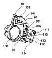
- FIG. 23 is a rear view of the second group holding cylinder in a photographing enabled state.
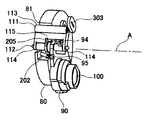
- FIG. 24 is a perspective view showing a lens frame and the like in a photographing enabled state.
- FIG. 25 is a perspective view showing a lens frame and the like when retracted.
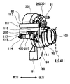
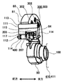
- FIG. 26 is a side view of the lens frame when retracted.
- FIG. 27 is a side view of the lens frame in a photographing enabled state
- FIG. 28 is a cross-sectional view when retracted according to the second embodiment.
- the second embodiment in addition to the first shaft 111, the second shaft 112, the link member 113, and the first biasing means 200 used as the camera shake correction mechanism 110 and the retracting mechanism, the second embodiment is used. Then, it has the spring member 400 and the moving means 410.
- the moving means 410 is indicated by a broken line.
- the notch 81 is formed in the shutter unit 80, and at least the same position of the second group holding cylinder 70 is opened.
- the spring member 400 urges the lens frame 90 in the direction away from the shutter unit 80 (the arrow rear side in the drawing).
- the lens frame 90 and the cylindrical portion 207 of the bias control member 204 are movable in the optical axis direction.
- the second shaft 112 can rotate with respect to the first shaft 111 via the link member 113, but the position in the optical axis direction does not change. Further, the second shaft 112 moves the lens frame 90 to the front side of the illustrated arrow in the optical axis direction against the bias of the spring member 400 with respect to the second group holding cylinder 70 and the shutter unit 80.
- a gap is provided between the wall edge 117 of the recess 115 and the first contact piece 205 in a direction parallel to the optical axis. This gap is larger than the movement amount when the lens frame 90 is retreated from the optical axis and further moved in the optical axis direction.
- 25 and 26 show a position where the lens frame 90 is moved out of the optical axis with respect to the link member 113 and further moved in the optical axis direction.
- FIG. 27 shows the position of the lens frame 90 in a photographing enabled state. Further, in FIG. 27, the amount of movement of the lens frame 90 in the optical axis direction is indicated by “S”. That is, in this example, when the lens barrel 1 is retracted, the lens frame 90 is moved to the subject side (the arrow front side in the drawing) with respect to the shutter unit 80 and the second group holding cylinder 70.
- the magnet 301 provided on the lens frame 90 and the coil 303 and the hall element 302 provided on the outer surface of the shutter unit 80 face each other in the front-rear direction (a direction parallel to the optical axis) in the photographing enabled state. To do. At this time, the shutter unit 80 and the lens frame 90 are urged away from each other by the spring member 400, and the lens frame 90 contacts the rear end of the link member 113. Therefore, the distance between the shutter unit 80 and the lens frame 90 in the optical axis direction is kept constant.
- the member constituting the outer surface of the shutter unit 80 is an opposing member, but the coil 303 may be disposed in the second group holding cylinder 70. In this case, the second group holding cylinder 70 is the opposing member.
- the second group holding cylinder 70 is further moved toward the image sensor.
- a part of the lens frame 90 comes into contact with the contact portion 411 (the moving unit 410) formed on the fixed cylinder 10 on the image sensor fixing portion side.
- the second group holding cylinder 70 is further moved toward the image sensor.
- the lens frame 90 is moved toward the subject against the urging of the spring member 400 with respect to the second group holding cylinder 70 and the shutter unit 80.
- FIG. 28 shows the state when the lens barrel is retracted.
- the lens barrel can be made thin when retracted by the amount that part of the lens barrel portion of the lens frame 90 is inserted into the cutout portion 81.
- the shutter unit 80 may be configured so that the lens frame 90 can be inserted by an amount corresponding to the plate thickness of the shutter unit 80 when retracted.
- the second shaft 112 is also used as a member for mounting the spring member 400, it is not necessary to provide a member for mounting the spring member. Therefore, the configuration is simplified and the cost can be reduced.
- the transition from the retracted state to the ready state for photographing in the lens barrel 1 is as follows. That is, the second group holding cylinder 70 and the shutter unit 80 move forward.
- the lens frame 90 is biased by the spring member 400 and moves away from the shutter unit 80. Further, when the second group holding cylinder 70 and the shutter unit 80 are integrally moved forward, the lens frame 90 rotates about the second shaft 112. Through a series of operations, the correction lens 100 enters the optical axis and becomes ready for photographing. At this time, the magnet 301 faces the coil 303.
- the lens barrel is shown in which the shutter unit 80 is disposed on the front side (subject side) and the lens frame 90 is disposed on the rear side (image plane side).
- the shutter unit 80 may be disposed rearward (image plane side) and the lens frame 90 may be disposed forward (subject side).
- such a lens barrel may be configured such that the lens frame 90 and the shutter unit 80 are relatively close to each other when the lens barrel is retracted.
- the lens frame 90 is rotated about the second shaft 112.
- the link member 113 and the lens frame 90 may be rotated together around the first shaft 111 and retracted.
- the regulated portion and the first regulating portion can be omitted, and the position where the second regulating portion is provided and the shape thereof may be changed as appropriate.
- orthogonal and parallel in the present application do not mean orthogonal or parallel in a strict sense, and may include errors that do not cause a problem when implementing the present invention. Good.
Landscapes
- Physics & Mathematics (AREA)
- General Physics & Mathematics (AREA)
- Optics & Photonics (AREA)
- Adjustment Of Camera Lenses (AREA)
- Lens Barrels (AREA)
- Studio Devices (AREA)
Description
この発明は、手ブレ補正機構を有したレンズ鏡胴に関する。
従来、レンズ鏡胴には、手ブレ補正機構が設けられる。一例として手ブレ補正機構は、次のように構成される。従来の手ブレ補正機構は、レンズ鏡胴に固定された固定部、固定部に設けられ支持枠を支持する第1ガイドシャフト、第2ガイドシャフトを介してレンズ枠を支持する支持枠、および補正用レンズを保持するレンズ枠を有する。レンズ鏡胴に固定された固定部は、この第1ガイドシャフトにより、支持枠を光軸に直交する面内の所定方向に案内可能に支持する。また支持枠は、第2ガイドシャフトによりレンズ枠を当該所定方向と直交する方向に案内可能に支持する。言い換えると、支持枠を第1の方向に案内するための第1ガイド機構が、固定部に設けられ、その上に第2の方向にレンズ枠を案内する第2ガイド機構が設けられる。すなわち、この手ブレ補正機構においては、レンズ枠が光軸に直交する面内で移動可能である(例えば、特許文献1参照)。
また他の例として、手ブレ補正機構は、レンズ鏡胴に固定された固定部、補正用レンズを保持するレンズ枠、および固定部とレンズ枠に挟持されたボールを有する。固定部とレンズ枠との間には、ボールを挟持する方向に付勢するバネが掛け渡される。このバネの付勢によりレンズ枠は、ボールを介して固定部に対し移動可能に載置される。すなわち、上記構成によれば、レンズ枠における光軸周りの回転が抑制されるとともに光軸に直交する面内を移動可能である(例えば、特許文献2参照)。
また他の例における手ブレ補正機構は、上述の手ブレ補正を行うためのガイド機構と、退避機構とを共に有する。退避機構は、沈胴時(collapsed state)にレンズの一部を光軸外へ退出させ、沈胴時の厚さを薄くする。この手ブレ補正機構では、手ブレ補正に用いられる振動枠により、補正用レンズを支持するレンズ枠が回動可能に支持される。またこの手ブレ補正機構は沈胴時において、退避機構により振動枠に対して補正用レンズを回動させて光軸外に退避させる(例えば、特許文献3)。
また、これらの手ブレ補正に用いるアクチュエータとしては、ボイスコイルモータ(VCM)が用いられることが多い。ボイスコイルモータは、固定部に対して光軸に直交する面内で移動可能に支持されている移動枠を有する。移動枠には永久磁石が固定される。また、固定部には、永久磁石に対向してホール素子及びコイルが固定される。
手ブレ補正機構により手ブレ補正を行う場合、ホール素子は永久磁石による磁界の変化に応じた信号を出力し、移動枠の位置を検知する。
しかしながら、上記特許文献1に記載されたレンズ鏡胴では、支持枠を第1の方向に案内する第1軸(第1ガイド機構)と、レンズ枠を第2の方向に案内する第2軸(第2ガイド機構)と、それぞれの軸に沿って案内される部材とがあるため、構成が複雑となる。また、このような構成によれば大型化やコストの増加につながるという問題点があった。
また、特許文献2に記載されたレンズ鏡胴は、バネによる付勢のバランスに依存して、光軸に直交する平面内でのレンズ枠の回転を防ぐ構造である。したがって、レンズ枠の回転を完全には防止することができないため、レンズ位置とレンズ位置を測定するセンサー出力との間にズレが発生する。その結果、手ブレ補正性能が低下する問題がある。また付勢による挟持のバランスを所定状態に保つためのバネの配置が、手ブレ補正機構におけるレイアウト上の制約となるおそれがある。その結果、手ブレ補正機構およびレンズ鏡胴の大型化につながるという問題点があった。
さらに、特許文献3に記載されたレンズ鏡胴では、レンズ枠を回動可能に支持したまま振動枠全体を移動させることによって、手ブレ補正が行われる。このような構成によれば、手ブレ補正時に移動させる対象が大型化し、また当該対象の質量の増加を招く。これらは、その対象を駆動するアクチュエータの大型化や特性劣化の要因となる。またこの手ブレ補正機構においては、アクチュエータが設けられた振動枠が、沈胴時においてもその位置を維持する。したがって、レンズ鏡胴を、沈胴時に薄くしようとする場合に支障となる。
本発明は、上記の問題を解決するものであり、小型化を図りつつ、コストを低減させることが可能な手ブレ補正機構を有するレンズ鏡胴を提供することを目的とする。
上記課題を解決するため、請求項1に記載のレンズ鏡胴は、撮影光学系の光軸に対して直交する面内で補正用レンズを移動させる手ブレ補正機構を有するレンズ鏡胴において、前記手ブレ補正機構は、前記光軸に対して平行に固定された第1軸と、前記第1軸を軸にして回動可能に設けられたリンク部材と、前記リンク部材に設けられ、前記光軸に対して平行な第2軸と、前記第2軸を軸にして回動可能に設けられ、前記補正用レンズを保持したレンズ枠と、を有することを特徴とする。
請求項2に記載のレンズ鏡胴は、請求項1に記載の発明において、沈胴時における前記レンズ枠の回動量が、手ブレ補正時よりも大きくなることで、前記補正用レンズが撮影時の光軸から退避されることを特徴とする。
請求項3に記載のレンズ鏡胴は、請求項1に記載の発明において、前記リンク部材の回動量を規制する第1規制部と、前記レンズ枠の回動量を規制する第2規制部と、を有することを特徴とする。
請求項4に記載のレンズ鏡胴は、請求項3に記載の発明において、前記第1規制部の一方端で前記リンク部材の回動を規制した際に前記第2規制部は前記レンズ枠の回動を規制し、沈胴時に、前記第1規制部の他方端で前記リンク部材の回動を規制し、かつ該沈胴時の前記レンズ枠の回動量が手ブレ補正時よりも大きくなることで、前記補正用レンズが撮影時の光軸から退避されることを特徴とする。
請求項5に記載のレンズ鏡胴は、請求項4に記載の発明において、前記レンズ枠には前記第2軸が貫通するスリーブ周りに被押動部が形成され、沈胴時に前記被押動部に係合部材が係合することにより、該沈胴時の前記レンズ枠の回動量が手ブレ補正時よりも大きくなることを特徴とする。
請求項6に記載のレンズ鏡胴は、請求項5に記載の発明において、沈胴時の前記レンズ枠の前記回動に対応して、前記レンズ枠を復帰させる方向に付勢する第1付勢手段を有することを特徴とする。
請求項7に記載のレンズ鏡胴は、請求項6に記載の発明において、前記第1付勢手段は、手ブレ補正時には前記レンズ枠を付勢せず、前記レンズ枠の回動量が手ブレ補正時よりも大きくなったときに付勢することを特徴とする。
請求項8に記載のレンズ鏡胴は、請求項1から7のいずれかに記載の発明において、前記レンズ枠を光軸方向に付勢する第2付勢手段を有することを特徴とする。
請求項9に記載のレンズ鏡胴は、請求項1から8のいずれかに記載の発明において、前記レンズ枠または撮影状態において前記レンズ枠に対向する対向部材のうちのいずれか一方に配置された磁石と、前記レンズ枠または前記対向部材の他方に配置されたコイルと、前記レンズ枠または前記対向部材の他方に配置されたホール素子と、を有することを特徴とする。
請求項10に記載のレンズ鏡胴は、請求項3に記載の発明において、前記レンズ枠または撮影状態において前記レンズ枠に対向する対向部材のうちのいずれか一方に配置された磁石と、前記レンズ枠または前記対向部材の他方に配置されたコイルと、前記レンズ枠または前記対向部材の他方に配置されたホール素子と、を有し、前記第1規制部の少なくとも一方端で前記リンク部材の回動を規制し、前記レンズ枠を第2規制部に当接させて前記ホール素子の出力の校正をおこなうことを特徴とする。
請求項11に記載のレンズ鏡胴は、請求項1から10のいずれかに記載の発明において、前記光軸上に配置され、その外縁部の一部に切り欠き部を備えたシャッターユニットをさらに有し、前記第1軸および前記第2軸は、光軸と平行な方向に前記切り欠き部を貫通するようにそれぞれ配置されることを特徴とする。
請求項12に記載のレンズ鏡胴は、請求項11に記載の発明において、前記補正用レンズは、前記シャッターユニットの直前方又は直後方に配置されることを特徴とする。
請求項13に記載のレンズ鏡胴は、撮影光学系の光軸に対して直交する面内で補正用レンズを移動させる手ブレ補正機構を有するレンズ鏡胴において、前記手ブレ補正機構は、前記補正用レンズを保持するレンズ枠と前記レンズ枠に対向する対向部材を有し、前記レンズ枠及び前記対向部材のうち、一方に磁石が配置され、他方にコイルと前記磁石の位置に応じた信号を出力する位置検出手段が配置され、沈胴時、前記レンズ枠は、前記磁石又は前記コイルと前記位置検出手段とを保持したまま前記光軸から退避されると共に、前記対向部材に対し光軸方向にも移動されることを特徴とする。
請求項14に記載のレンズ鏡胴は、請求項13に記載の発明において、前記レンズ枠は、前記光軸方向における移動後において、前記磁石と前記コイル又は前記位置検出手段とが、前記光軸に直交する同一平面を含む位置となるように位置することを特徴とする。
請求項15に記載のレンズ鏡胴は、請求項13又は14に記載の発明において、前記レンズ枠は前記対向部材に対して像面側に配置され、沈胴時に、前記レンズ枠を前記対向部材に対して被写体側に移動させることを特徴とする。
請求項16に記載のレンズ鏡胴は、請求項13から15のいずれかに記載の発明において、枠保持部材に配置され、前記光軸と平行に固定された第1軸と、前記第1軸を軸にして回動可能に設けられたリンク部材と、前記リンク部材に設けられた前記光軸と平行な第2軸と、を有し、前記レンズ枠は、前記第2軸を軸にして回動可能に設けられることを特徴とする。
請求項17に記載のレンズ鏡胴は、請求項13から16のいずれかに記載の発明において、沈胴時における、前記レンズ枠の回動量が手ブレ補正時よりも大きくなることで、前記補正用レンズが撮影時の光軸から退避されることを特徴とする。
本発明のレンズ鏡胴によれば、小型化及びコストの低減が可能な手ブレ補正機構を有したレンズ鏡胴を提供することが可能となる。
(第1の実施の形態)
第1の実施の形態に係るレンズ鏡胴1について各図を参照して説明する。図1は、レンズ鏡胴1を構成する2群保持筒70を光軸Aにおける後方(撮像素子側)から見たときの図である。
第1の実施の形態に係るレンズ鏡胴1について各図を参照して説明する。図1は、レンズ鏡胴1を構成する2群保持筒70を光軸Aにおける後方(撮像素子側)から見たときの図である。
以下の説明においては、図1に示すように、短針を撮影光学系の光軸Aを中心として時計回りに回転させたと仮定したとき、光軸Aにおける後方から見て3時にあたる方向を右方向と記載することがある。同様に、6時にあたる方向を下方向、9時にあたる方向を左方向、12時にあたる方向を上方向と記載することがある。また、当該左右方向をX方向と記載し、当該上下方向をY方向とそれぞれ記載することがある。さらに、光軸方向において、撮影対象側を前方、撮像素子側を後方、光軸方向を前後方向とそれぞれ記載することがある。
図2は沈胴時(非撮影時)のレンズ鏡胴1の斜視図である。図3は撮影可能状態の一つであるワイド時のレンズ鏡胴1の斜視図である。図4は撮影可能状態の一つであるテレ時のレンズ鏡胴1の斜視図である。図5は図2のV-V線断面図である。図6は図3のVI-VI線断面図である。図7は図4のVII-VII線断面図である。
図2~図7に示すように、レンズ鏡胴1は、固定筒10、直進筒A20、回転筒A30、直進筒B40、前筒50、回転筒B60、2群保持筒70、シャッターユニット80、レンズ枠90、及び撮影光学系を有する。
撮影光学系は、第1光学要素11、第2光学要素12、及び、補正用レンズ100を有する(図1,図5~図7参照)。なお以下において、補正用レンズ群を単に補正用レンズ100と記載することがある。また、以下においては、3群で構成されたズーム撮影光学系を用いて説明するが、本実施形態はこの例に限られない。
補正用レンズ100は、撮影時に撮影光学系の光軸に直交する面内でX方向及びY方向に変位される。この変位によって、手ブレによる被写体像の像ブレが低減される。
(固定筒10)
固定筒10には、撮像素子固定部、第2光学要素12、及び出力ギア14(図2~4参照)が設けられる。出力ギア14は、モータ(図示省略)により回転される。撮像素子固定部は、レンズ鏡胴の光軸方向における後端部に設けられた平板状の部分である。撮像素子としては、CCD(Charge Coupled Device)型イメージセンサ、あるいはC-MOS(Complementary Metal Oxide Semiconductor)型イメージセンサ等が用いられる。撮像素子は、撮影光学系が形成する被写体像を電気的な信号に変換する。第2光学要素は、光軸における第1光学要素の後方に配置される。出力ギア14は、回転筒A30を回転させるものである。
固定筒10には、撮像素子固定部、第2光学要素12、及び出力ギア14(図2~4参照)が設けられる。出力ギア14は、モータ(図示省略)により回転される。撮像素子固定部は、レンズ鏡胴の光軸方向における後端部に設けられた平板状の部分である。撮像素子としては、CCD(Charge Coupled Device)型イメージセンサ、あるいはC-MOS(Complementary Metal Oxide Semiconductor)型イメージセンサ等が用いられる。撮像素子は、撮影光学系が形成する被写体像を電気的な信号に変換する。第2光学要素は、光軸における第1光学要素の後方に配置される。出力ギア14は、回転筒A30を回転させるものである。
固定筒10の内面には、直進筒A20を光軸方向に案内するための第1ガイド(図示省略)と、回転筒A30を光軸方向に移動させるための第1カム(図示省略)とが設けられる。
(直進筒A20)
直進筒A20は、回転筒A30とバヨネット(bayonet)結合されることで、回転筒A30と一体的に光軸方向に移動される。直進筒A20は、第1ガイドにより光軸方向に案内される。直進筒A20の内面には、直進筒B40を光軸方向に案内するための第2ガイド(図示省略)と、回転筒B60を光軸方向に移動させるための第2カム(図示省略)とが設けられる。
直進筒A20は、回転筒A30とバヨネット(bayonet)結合されることで、回転筒A30と一体的に光軸方向に移動される。直進筒A20は、第1ガイドにより光軸方向に案内される。直進筒A20の内面には、直進筒B40を光軸方向に案内するための第2ガイド(図示省略)と、回転筒B60を光軸方向に移動させるための第2カム(図示省略)とが設けられる。
(回転筒A30)
回転筒A30は、その後端部に駆動ギア13を有する。駆動ギア13は、出力ギア14に噛み合わされる。回転筒A30は、駆動ギア13が回転されることで、回転しながら第1カムにより光軸方向に移動される。回転筒A30の内面には、回転筒B60に回転力を伝達するための伝達キー(図示省略)と、回転筒B60のカムピンが貫通する貫通穴(図示省略)が設けられる。
回転筒A30は、その後端部に駆動ギア13を有する。駆動ギア13は、出力ギア14に噛み合わされる。回転筒A30は、駆動ギア13が回転されることで、回転しながら第1カムにより光軸方向に移動される。回転筒A30の内面には、回転筒B60に回転力を伝達するための伝達キー(図示省略)と、回転筒B60のカムピンが貫通する貫通穴(図示省略)が設けられる。
(直進筒B40)
直進筒B40は、回転筒B60とバヨネット結合されることで、回転筒B60と一体的に光軸方向に移動される。直進筒B40は、第2ガイドにより光軸方向に案内される。直進筒B40の内面には、前筒50を光軸方向に案内するための第3ガイド(図示省略)と、2群保持筒70を光軸方向に案内するための第4ガイド(図示省略)とを有する。第3ガイドと第4ガイドとは一体的に設けられる。
直進筒B40は、回転筒B60とバヨネット結合されることで、回転筒B60と一体的に光軸方向に移動される。直進筒B40は、第2ガイドにより光軸方向に案内される。直進筒B40の内面には、前筒50を光軸方向に案内するための第3ガイド(図示省略)と、2群保持筒70を光軸方向に案内するための第4ガイド(図示省略)とを有する。第3ガイドと第4ガイドとは一体的に設けられる。
(前筒50)
前筒50は、第3ガイドにより光軸方向に案内される。前筒50は、回転筒B60の第3カム(図示省略)により光軸方向に移動される。前筒50には第1光学要素11が固定される。
前筒50は、第3ガイドにより光軸方向に案内される。前筒50は、回転筒B60の第3カム(図示省略)により光軸方向に移動される。前筒50には第1光学要素11が固定される。
(回転筒B60)
回転筒B60に回転筒A30の回転が伝達されることにより、回転筒B60は、回転しながら第2カムにより光軸方向に移動される。回転筒B60の外面には、前筒50を光軸方向に直進させるための第3カムが設けられ、回転筒B60の内面には、2群保持筒70を光軸方向に直進させるための第4カム(図示省略)が設けられる。
回転筒B60に回転筒A30の回転が伝達されることにより、回転筒B60は、回転しながら第2カムにより光軸方向に移動される。回転筒B60の外面には、前筒50を光軸方向に直進させるための第3カムが設けられ、回転筒B60の内面には、2群保持筒70を光軸方向に直進させるための第4カム(図示省略)が設けられる。
(2群保持筒70)
次に、2群保持筒70について図1、及び図8~図11を参照して説明する。図8はシャッターユニットを斜め前方から見たときの斜視図である。図9は2群保持筒を斜め後方から見たときの斜視図である。図10はレンズ枠を斜め後方から見たときの斜視図である。図11は2群保持筒を斜め前方から見たときの斜視図である。
次に、2群保持筒70について図1、及び図8~図11を参照して説明する。図8はシャッターユニットを斜め前方から見たときの斜視図である。図9は2群保持筒を斜め後方から見たときの斜視図である。図10はレンズ枠を斜め後方から見たときの斜視図である。図11は2群保持筒を斜め前方から見たときの斜視図である。
図1、及び図9~図11に示すように、2群保持筒70には、シャッターユニット80、レンズ枠90、第1軸111、第2軸112、リンク部材113、及び、第1付勢手段200が設けられる。
2群保持筒70は、光軸に沿って配置された筒軸と、第2規制部712と、一対のフランジ71とを有する。
図9及び図11に示すように、一対のフランジ71は、光軸方向でシャッターユニット80の前方位置にある2群保持筒70の前端部、及びシャッターユニット80の後方位置である2群保持筒70の後端部に設けられる。光軸方向の前後一対のフランジ71間の距離は、光軸方向に十分な長さを有する。図1に示す例において、当該前端部側のフランジ71は、2群保持筒70の内周に沿って、ほぼ7時からほぼ9時までの範囲に設けられる。当該前端部側のフランジ71のほぼ8時の位置には、回動量制限用の穴である第1規制部711が設けられる。第1規制部711には、後述する第2軸112の端部が挿入される。この構成により、第2軸112の回動量が規制され、レンズ枠90の略左右方向の回動量が制限される。すなわち、手ブレ補正時における補正用レンズ100の回動量が制限範囲内に規制される(図17、図18参照)。
図1に示すように、第2規制部712は、2群保持筒70の内周に沿って、ほぼ12時の位置に設けられる。第2規制部712は、上溝壁713、下溝壁714、及び左溝壁715を有する。第2規制部712の右端は開放される。第2規制部712内に、レンズ枠90に設けられた被規制部91が挿入される。また、第2軸112が第1規制部711の左端に当接した場合、レンズ枠90の回動による略上下方向の移動が制限される。この構成により、調整時における補正用レンズ100の回動量が制限範囲内に規制される。被規制部91と第2規制部712との関係については後述する。
なお、レンズ鏡胴1の沈胴時において、補正用レンズ100を上記制限範囲内から外に退避させる場合は、第2軸112が第1規制部711の右端に当接された状態で、レンズ枠90が回動される。その結果、被規制部91が第2規制部712の右端の開放部分から離脱される。また、図1及び図9に示すように、2群保持筒70は、ほぼ6時を中心にして、ほぼ5時からほぼ7時までの間に、補正用レンズ100及びその周辺部を通すための通過口72が設けられている。この通過口72により、被規制部91が離脱してさらにレンズ枠90および補正用レンズ100が回動されると、補正用レンズ100は、光軸上からほぼ6時の位置に退避される。
(シャッターユニット80)
次に、シャッターユニット80について、図1、及び図8~図12を参照して説明する。図12はシャッターユニット80を前方から見たときの正面図である。
次に、シャッターユニット80について、図1、及び図8~図12を参照して説明する。図12はシャッターユニット80を前方から見たときの正面図である。
図1、及び図8~図12に示すように、シャッターユニット80は、2群保持筒70内に固定される。
図9に示す例において、シャッターユニット80(図8参照)は、補正用レンズ100の前方の近傍位置に配置される。図12に示すように、シャッターユニット80は、その外縁部の一部に切り欠き部81を備える。切り欠き部81は、図12でほぼ3時からほぼ5時の間(図1でほぼ7時からほぼ9時の間)に設けられる。
図9及び図11に示すように、切り欠き部81には、第1軸111、第2軸112及びリンク部材113が配置される。これらは、手ブレ補正機構110及び補正用レンズ100を光軸外に退避させる場合に用いられる。切り欠き部81により、手ブレ補正機構110および退避機構を設けても、2群保持筒70の径の増大を抑制することが可能である。また、第1軸111及び第2軸112をシャッターユニット80の表裏にわたって貫通して配置できる。この構成により、軸長を十分長くできる。また、光軸に対するレンズ枠90の傾きを抑えることができる。また、レンズ枠90の取付け精度を高めることができる。なお、シャッターユニット80が、補正用レンズ100の後方の近傍位置に配置された場合でも同様の効果を得ることができる。
図9及び図11に示すように、切り欠き部81を遮光する遮光手段が設けられる。それにより、光漏れを防止することが可能である。遮光手段の一例は、前述したフランジ71である。フランジ71は、切り欠き部81を挟んで、光軸方向における前方および後方に配置される。すなわち、フランジ71は、切り欠き部81から光が漏れたり、切り欠き部81へ光が差し込まないように構成される。なお、フランジ71は遮光手段としての機能を有し、さらに、後述するように第1軸111を支持する機能等を有する。この点からも、小型化及びコストの低減が可能である。
次に、レンズ鏡胴1の基本的な動作について図2から図7を参照して説明する。
(沈胴状態-撮影可能状態)
図2及び図5に示す沈胴状態においては、前筒50に固定される第1光学要素11と固定筒10に保持される第2光学要素12とが近接し、補正用レンズ100は光軸外に退避される。
図2及び図5に示す沈胴状態においては、前筒50に固定される第1光学要素11と固定筒10に保持される第2光学要素12とが近接し、補正用レンズ100は光軸外に退避される。
図2及び図5に示す沈胴状態において、出力ギア14が例えば正方向に回転されると、その回転が回転筒A30に伝達され、さらに回転筒B60に伝達される。回転筒A30は、回転しながら、固定筒10の第1カムにより光軸方向に沿って前方に移動される。直進筒A20は、固定筒10の第1ガイドにより案内され、回転せずに、回転筒A30と共に光軸方向に沿って前方に移動される。
回転筒B60は、回転されるとともに、直進筒A20の第2カムにより光軸方向に沿って前方に移動される。直進筒B40は、直進筒A20の第2ガイドにより案内され、回転せずに、回転筒B60と共に光軸方向に沿って前方に移動される。
また、回転筒B60が回転されると、前筒50が直進筒B40の第3ガイドに案内され、回転筒B60の第3カムにより光軸方向に沿って前方に移動される(図3及び図6参照)。図3および図6に示す状態は、撮影可能状態であってワイド端(wide end)の状態を示している。この状態においては、固定筒10に対して前筒50が大きく前方に移動されるため、第1光学要素11と第2光学要素12との間の光軸上の隙間は広がる。この沈胴状態からワイド端への移行過程で、レンズ枠90は第2軸112を軸として大きく回動させられ、補正用レンズ100が広くなった光軸上に復帰する。撮影可能状態であるワイド端では、レンズ枠90を第1軸111及び/又は第2軸112を軸として回動させることにより、補正用レンズ100を移動させて手ブレ補正を行うことができる。
(ワイド端→テレ端(telephoto end)への変倍)
撮影可能状態における、図3及び図6に示すワイド端の状態から、出力ギア14をさらに正方向に回転させると、回転筒A30は、回転しながら、固定筒10の第1カムにより光軸方向に沿って前方に移動される(図4及び図7参照)。直進筒A20は、固定筒10の第1ガイドにより案内され、回転せずに、回転筒A30と共に光軸方向に沿って前方に移動される。
撮影可能状態における、図3及び図6に示すワイド端の状態から、出力ギア14をさらに正方向に回転させると、回転筒A30は、回転しながら、固定筒10の第1カムにより光軸方向に沿って前方に移動される(図4及び図7参照)。直進筒A20は、固定筒10の第1ガイドにより案内され、回転せずに、回転筒A30と共に光軸方向に沿って前方に移動される。
回転筒B60が回転されると、2群保持筒70が直進筒B40の第4ガイドに案内され、回転筒B60の第4カムにより光軸方向に沿って前方に移動され、図4及び図7に示すテレ端まで変倍する。この、図3及び図6に示す撮影可能状態(ワイド端)から図4及び図7に示す撮影可能状態(テレ端)までの所望の各ポジションにおいても、上述と同様に、レンズ枠90を第1軸111及び/または第2軸112を軸として回動させることにより、レンズ枠90が保持する補正用レンズ100を移動させる。この動作により、手ブレ補正が行われる。
(テレ端→ワイド端への変倍)
撮影可能状態における、図4及び図7に示すテレ端の状態から、出力ギア14が例えば逆方向に回転されると、その回転が回転筒A30に伝達される。さらに回転が回転筒B60にも伝達される。
撮影可能状態における、図4及び図7に示すテレ端の状態から、出力ギア14が例えば逆方向に回転されると、その回転が回転筒A30に伝達される。さらに回転が回転筒B60にも伝達される。
回転筒A30は、回転しながら、固定筒10の第1カムにより光軸方向に沿って後方に移動される。直進筒A20は、固定筒10の第1ガイドにより案内され、回転せずに、回転筒A30と共に光軸方向に移動される。
回転筒B60が回転されると、2群保持筒70が直進筒B40の第4ガイドに案内され、回転筒B60の第4カムにより光軸方向に沿って後方に移動される(図3及び図6参照)。
(撮影可能状態→沈胴状態への移行)
撮影可能状態におけるワイド端の状態からさらに、出力ギア14が逆方向に回転されると、回転筒A30は、回転しながら、固定筒10の第1カムにより光軸方向に沿って後方に移動される。直進筒A20は、固定筒10の第1ガイドにより案内され、回転せずに、回転筒A30と共に光軸方向に移動される。
撮影可能状態におけるワイド端の状態からさらに、出力ギア14が逆方向に回転されると、回転筒A30は、回転しながら、固定筒10の第1カムにより光軸方向に沿って後方に移動される。直進筒A20は、固定筒10の第1ガイドにより案内され、回転せずに、回転筒A30と共に光軸方向に移動される。
回転筒B60が回転されると、回転筒B60は、直進筒A20の第2カムにより光軸方向に沿って後方に移動される。直進筒B40は、直進筒A20の第2ガイドにより案内され、回転せずに、回転筒B60と共に光軸方向に移動される。
また、回転筒B60が回転されると、前筒50が直進筒B40の第3ガイドに案内され、回転筒B60の第3カムにより光軸方向に沿って後方に移動される。この動作の結果、レンズ鏡胴1の沈胴状態に移行する(図2及び図5参照)。
図2及び図5に示す沈胴状態においては、固定筒10に対して前筒50が大きく後方に移動されて固定筒10に接近することにより、光軸方向における第1光学要素11と第2光学要素12との間の隙間が狭くなる。このように撮影状態におけるワイド端の状態から沈胴状態へ移行する過程で、レンズ枠90が第2軸112を軸として手ブレ補正時より大きく回動されることにより、補正用レンズ100が光軸外に退避される。この構成により、レンズ鏡胴1の沈胴時の厚さを薄くすることが可能である。
次に、レンズ枠90を第1軸111及び/または第2軸112を軸として回動させることにより、手ブレ補正を行う構成(手ブレ補正機構110)について説明する。併せてレンズ鏡胴1の沈胴時に補正用レンズ100が大きく光軸外へ退避される構成(退避機構)について説明する。
〔手ブレ補正機構110〕
先ず、手ブレ補正機構110について図1、図9~図11及び図13~図16を参照して説明する。その後、退避機構について説明する。図13はレンズ枠90を斜め前方から見たときの斜視図である。
先ず、手ブレ補正機構110について図1、図9~図11及び図13~図16を参照して説明する。その後、退避機構について説明する。図13はレンズ枠90を斜め前方から見たときの斜視図である。
図1、図9~図11及び図13に示すように、手ブレ補正機構110は、第1軸111、第2軸112、リンク部材113及びレンズ枠90を有する。
(第1軸111)
図1に示すように、第1軸111はフランジ71のほぼ9時の位置に固定される。第1軸111の長さは前述のように、前後一対のフランジ71に架け渡され、十分な長さを有し、光軸に対する第1軸111の傾きが小さく抑えられる。なお、第1軸111は、光軸に対して固定され、光軸に略平行な軸であればよい。また本実施形態の説明において「光軸に対して固定」と記載した場合、光軸に直交する面において移動しないことを示す。
図1に示すように、第1軸111はフランジ71のほぼ9時の位置に固定される。第1軸111の長さは前述のように、前後一対のフランジ71に架け渡され、十分な長さを有し、光軸に対する第1軸111の傾きが小さく抑えられる。なお、第1軸111は、光軸に対して固定され、光軸に略平行な軸であればよい。また本実施形態の説明において「光軸に対して固定」と記載した場合、光軸に直交する面において移動しないことを示す。
(リンク部材113)
リンク部材113は、第1軸111を軸として回動可能に軸支される。リンク部材113は、2群保持筒70の内周に沿って配置される。図1の例においてリンク部材113は、ほぼ7時からほぼ9時の区間に配置される。この区間は、シャッターユニット80の切り欠き部81が設けられた区間に相当する(図1、図12参照)。2群保持筒70および切り欠き部81により、リンク部材113をスペース効率良く配置することが可能である。リンク部材113は、光軸方向の前後一対のフランジ71の間に嵌め込まれるように配置される。前後一対のフランジ71間の距離は、光軸方向で切り欠き部81を貫通してシャッターユニット80の表裏にわたって配置されるため十分に長い。また、その隙間に嵌め込まれるリンク部材113も同様に光軸方向に十分に長い。この構成によれば第1軸111及びリンク部材113の光軸に対する倒れを抑制できる。
リンク部材113は、第1軸111を軸として回動可能に軸支される。リンク部材113は、2群保持筒70の内周に沿って配置される。図1の例においてリンク部材113は、ほぼ7時からほぼ9時の区間に配置される。この区間は、シャッターユニット80の切り欠き部81が設けられた区間に相当する(図1、図12参照)。2群保持筒70および切り欠き部81により、リンク部材113をスペース効率良く配置することが可能である。リンク部材113は、光軸方向の前後一対のフランジ71の間に嵌め込まれるように配置される。前後一対のフランジ71間の距離は、光軸方向で切り欠き部81を貫通してシャッターユニット80の表裏にわたって配置されるため十分に長い。また、その隙間に嵌め込まれるリンク部材113も同様に光軸方向に十分に長い。この構成によれば第1軸111及びリンク部材113の光軸に対する倒れを抑制できる。
リンク部材113の一端部は、上記の長い第1軸111を軸にして回動可能に支持されるため、リンク部材113の傾きを小さく抑えることができる。それにより、リンク部材113の取付け精度を高めることができる。その結果、レンズ枠90の取付け精度を高めることができる。
図14は光軸に直交する平面でリンク部材113を切断したときの図である。図15は撮影可能状態におけるレンズ枠等の斜視図である。図16はレンズ枠が光軸外に退避したときの斜視図である。
図14~図16に示すように、リンク部材113の他端部は、凸部114、及び当該凸部114より一端部からの距離が短い凹部115を有する。リンク部材113の他端部において、凸部114は前縁部から後縁部にかけて、凹部115を挟むようにして設けられる(図15参照)。またレンズ枠90の取付精度を高めるため、凹部115の開口幅を光軸方向において十分に長くしてもよい。
(第2軸112)
図9及び図11に示すように、第2軸112は、リンク部材113の他端部に設けられる。なお、第2軸112は、リンク部材113において、第1軸111が設けられる位置とは異なる位置に設けられていればよい。第2軸112は、光軸に平行な軸である。レンズ枠90の取付け精度を高めるため、第2軸112は、前縁部側の凸部114と後縁部側の凸部114とに架け渡されるような十分なガイド長を有するように構成されていてもよい。このような構成によれば、光軸に対する第2軸112の傾きが小さく抑えられる。第2軸112の前端部及び後端部は前縁部側の凸部114及び後縁部側の凸部114をそれぞれ貫通する(図15参照)。
図9及び図11に示すように、第2軸112は、リンク部材113の他端部に設けられる。なお、第2軸112は、リンク部材113において、第1軸111が設けられる位置とは異なる位置に設けられていればよい。第2軸112は、光軸に平行な軸である。レンズ枠90の取付け精度を高めるため、第2軸112は、前縁部側の凸部114と後縁部側の凸部114とに架け渡されるような十分なガイド長を有するように構成されていてもよい。このような構成によれば、光軸に対する第2軸112の傾きが小さく抑えられる。第2軸112の前端部及び後端部は前縁部側の凸部114及び後縁部側の凸部114をそれぞれ貫通する(図15参照)。
第2軸112の前端部及び後端部は、リンク部材113の回動量制限用の穴である第1規制部711内に挿入される。第2軸112の直径と、第1規制部711の左右方向(X方向)の幅との関係を適宜設定することで、手ブレ補正時の、第2軸112の略X方向に回動可能な範囲が定められる。すなわち、補正用レンズ100の略X方向の回動可能な範囲が定められる(図1、図11参照)。
(レンズ枠90)
図1及び図13に示すように、レンズ枠90は補正用レンズ100を保持する。図15及び図16に示すように、レンズ枠90は、基端部がリンク部材113の第2軸112側に嵌め込まれ、第2軸112は貫通しており、第2軸112を軸にして回動可能となされる。
図1及び図13に示すように、レンズ枠90は補正用レンズ100を保持する。図15及び図16に示すように、レンズ枠90は、基端部がリンク部材113の第2軸112側に嵌め込まれ、第2軸112は貫通しており、第2軸112を軸にして回動可能となされる。
レンズ枠90の基端部は光軸方向で十分に長いため、第2軸112に対して(第2軸112に直交する平面に対して)レンズ枠90の基端部の傾きを小さく抑えることが可能である。それにより、レンズ枠90の取付け精度を高めることができる。
図1、図13及び図14に示すように、レンズ枠90には、被規制部91、係止部92(図20参照)、当接部93、及び、被押動部94が設けられる。
図1に示すように、被規制部91はレンズ枠90のほぼ12時の位置に設けられる。被規制部91は、撮影可能状態では第2規制部712の上溝壁713と下溝壁714との間に位置する。被規制部91の大きさと、第2規制部712の上下方向の幅(上溝壁713と下溝壁714との間の間隔、すなわちY方向の幅)との関係は適宜設定される。この設定により、手ブレ補正時の、レンズ枠90のY方向に回動可能な範囲が定められる。すなわち、補正用レンズ100の上下方向(Y方向)の回動可能な範囲が定められる。なお、係止部92及び当接部93は第2軸112の周辺に配置される(図14、図20及び図21参照)。係止部92及び当接部93の詳細については後述する。
以上の手ブレ補正機構110を用いて、手ブレ補正を行うことができる。手ブレ補正のとき、レンズ枠90が第1軸111及び/または第2軸112を軸として回動される。この動作により、レンズ枠90に保持された補正用レンズ100が光軸に直交する面の制限範囲内において移動される。
上述のように、第1軸111及び第2軸112のガイド長を長く構成することで、レンズ枠90の取付け精度を高くでき、リンク部材113及びレンズ枠90の姿勢を保つことができる。また、光軸に対するレンズ枠90の傾きを抑えることができる。さらに、そのための構造が、第1軸111、第2軸112及びリンク部材113を用いた同一の構成により実現できる。したがって、簡易な構成において、小型化及びコストの低減が可能である。さらに、第1軸111及び第2軸112を軸として回動させる構成は、軸を光軸に直交する面に配置してガイドとしてスライドさせる構成に比べて摩擦の影響が少ない。したがって、手ブレ補正の性能を向上させることができる。
なお、本実施形態の説明において「レンズ枠90を第1軸111及び/または第2軸112を軸として回動させる」と記載した場合、
(1)レンズ枠90を、リンク部材113と一体的に第1軸111を軸として回動させること、
(2)リンク部材113を回動させず、第2軸112を軸としてレンズ枠90を回動させること、
(3)リンク部材113を第1軸111を軸として回動させ、かつ、レンズ枠90を第2軸112を軸として回動させること、
を示す。また、「レンズ枠90の回動」を、軸回りにおける回動としてとらえる場合と、手ブレ補正におけるレンズ枠90の移動としてとらえる場合とで、その態様が異なる。すなわち手ブレ補正において、レンズ枠90及び補正用レンズ100は、上記制限範囲内において僅かに移動される。したがって、補正用レンズ100の移動は、実効的には直線的な微少運動としてとらえられる。
(1)レンズ枠90を、リンク部材113と一体的に第1軸111を軸として回動させること、
(2)リンク部材113を回動させず、第2軸112を軸としてレンズ枠90を回動させること、
(3)リンク部材113を第1軸111を軸として回動させ、かつ、レンズ枠90を第2軸112を軸として回動させること、
を示す。また、「レンズ枠90の回動」を、軸回りにおける回動としてとらえる場合と、手ブレ補正におけるレンズ枠90の移動としてとらえる場合とで、その態様が異なる。すなわち手ブレ補正において、レンズ枠90及び補正用レンズ100は、上記制限範囲内において僅かに移動される。したがって、補正用レンズ100の移動は、実効的には直線的な微少運動としてとらえられる。
次に、レンズ枠90の回動量規制について、図1及び図17~図19を参照してより詳しく説明する。図1は、左端位置に移動させたレンズ枠90を示す図である。図17は、右端位置に移動させたレンズ枠90を示す図である。図18は、上端位置に移動させたレンズ枠90を示す図である。図19は、下端位置に移動させたレンズ枠90を示す図である。
(レンズ枠90の回動量の規制)
図1に示すように、レンズ枠90が左方に移動されると、第2軸112は第1規制部711の左縁に当接する。図17に示すように、レンズ枠90が右方に移動されると、第2軸112は第1規制部711の右縁に当接する。図18に示すように、第2軸112が第1規制部711の左縁に当接した状態で、レンズ枠90を上方に移動させると、被規制部91は第2規制部712の上溝壁713に当接する。図19に示すように、第2軸112が第1規制部711の左縁に当接した状態で、レンズ枠90を下方に移動させると、被規制部91が第2規制部712の下溝壁714に当接する。
図1に示すように、レンズ枠90が左方に移動されると、第2軸112は第1規制部711の左縁に当接する。図17に示すように、レンズ枠90が右方に移動されると、第2軸112は第1規制部711の右縁に当接する。図18に示すように、第2軸112が第1規制部711の左縁に当接した状態で、レンズ枠90を上方に移動させると、被規制部91は第2規制部712の上溝壁713に当接する。図19に示すように、第2軸112が第1規制部711の左縁に当接した状態で、レンズ枠90を下方に移動させると、被規制部91が第2規制部712の下溝壁714に当接する。
一方、第2軸112が第1規制部711の右縁に当接した状態では、第2規制部712の右端は開放されている。この状態では、レンズ枠90を下方向に回動させた際の、被規制部91の下方向への移動が規制されていない。第2軸112が第1規制部711の右縁に当接した状態では、レンズ枠90に設けられた付勢制御部材204の第1被当接片205(図20及び図21参照)と、リンク部材113の凹部115の辺縁とが当接する。この状態により、被規制部91の下方向への移動が規制される。この方向の規制については後述する。この構成によれば、手ブレ補正時に、レンズ枠90、すなわち補正用レンズ100の移動を制限範囲内に規制する。
なお「制限範囲」とは、手ブレ補正において、レンズ枠90及び補正用レンズ100が運動し得る範囲をいう。
(位置検出手段)
次に、位置検出手段300について、図1、図10及び図13を参照して説明する。
次に、位置検出手段300について、図1、図10及び図13を参照して説明する。
図1、図10及び図13に示すように、位置検出手段300は、磁石301とホール素子302とを有する。
図1に示すように、磁石301は、レンズ枠90の9時の位置と12時の位置とにそれぞれ配置される。
図13に示すホール素子302は、シャッターユニット80の外面に、磁石301と対向するように配置される。ホール素子302は、光軸に直交する面における互いに直交するX方向及びY方向のレンズ枠90の位置を検出する。磁石301及びホール素子302を用いてレンズ枠90の位置検出を行うことにより、補正用レンズ100を精度良く制御することができ、かつその構成は簡易である。なお、ホール素子302は2群保持筒70に配置されてもよい。
(位置情報の校正)
次に、位置情報の校正について説明する。ホール素子302により検出されたレンズ枠90の位置情報は、実際のレンズ枠90の位置情報とずれが生じることがある。本例では、レンズ枠90の予め定められた位置情報に基づいて、検出された位置情報を校正する。
次に、位置情報の校正について説明する。ホール素子302により検出されたレンズ枠90の位置情報は、実際のレンズ枠90の位置情報とずれが生じることがある。本例では、レンズ枠90の予め定められた位置情報に基づいて、検出された位置情報を校正する。
例えば、レンズ枠90を、第1規制部および第2規制部それぞれの両端に位置させたときの出力を検出し、その中心をレンズ枠90の中心位置とする。さらにあらかじめ求められた両端間の移動量と、当該出力の関係から上記位置情報を校正する。なお、位置情報の構成については、当該実施例に限られない。
レンズ枠90の位置情報の校正により、手ブレ補正の性能を高めることができる。なお、この校正は、不図示の手ブレ補正のための制御回路により行われる。
補正用レンズ100を移動させる手段としては、磁石301及びコイル303を有する。コイル303は、シャッターユニット80(図10及び図13では図示省略)の外面に配置される。コイル303は、磁石301に対して対向するように配置される。なお、コイル303は2群保持筒70に配置されてもよい。
手ブレ補正においては、磁石301がコイル303から力を受け、レンズ枠90が第1軸111及び/または第2軸112を軸として回動する。この回動により、補正用レンズ100が光軸に直交する面内で移動する。このとき、ホール素子302によりレンズ枠90の位置を検出し、検出結果に応じてレンズ枠90が所望の位置となるように制御が行われる。磁石301及びコイル303を用いてレンズ枠90が駆動されるので、小型化及びコストの低減が可能であり、かつその構成は簡易である。なお、実施形態では、磁石301がレンズ枠90に配置され、ホール素子302及びコイル303が、シャッターユニット80(あるいは、2群保持筒70)に配置されている。ただしこのような構成に限られない。例えば逆の態様、すなわち、磁石301がシャッターユニット80(あるいは、2群保持筒70)に配置され、ホール素子302及びコイル303がレンズ枠90に配置されてもよい。すなわち、シャッターユニット80あるいは、2群保持筒70は対向部材の一例に相当する。
また、後述するようにレンズ枠90が光軸外に退避した場合は、コイル303と磁石301が対向しなくなるため、駆動力を発生することができない。したがって、コイル303と磁石301が対向する範囲内において、コイル303による駆動で手振れ補正が行われる。これに対し、退避位置から当該範囲内へ向かうレンズ枠90の移動は、第1付勢手段200の付勢バネ201の付勢力により行われる。
〔退避機構〕
次に、退避機構について図14、図20から図22を参照して説明する。図14はレンズ枠90が光軸外に退避し、復帰する方向に付勢力を受けるときの状態を示す図である。図20は、付勢力の発生と消失とが切り替わるときの状態を示す図である。図21は、レンズ枠90が復帰し付勢力が消失した、手ブレ補正時の状態を示す図である。
次に、退避機構について図14、図20から図22を参照して説明する。図14はレンズ枠90が光軸外に退避し、復帰する方向に付勢力を受けるときの状態を示す図である。図20は、付勢力の発生と消失とが切り替わるときの状態を示す図である。図21は、レンズ枠90が復帰し付勢力が消失した、手ブレ補正時の状態を示す図である。
図14、図20及び図21に示すように、退避機構は、手ブレ補正機構110の構成として用いられる第1軸111、第2軸112及びリンク部材113に加えて、第1付勢手段200を有する。このように、手ブレ補正機構110及び退避機構に、共通の構成を用いるので、小型化及びコストの低減が可能となる。
(第1付勢手段200)
次に、第1付勢手段200について、図14、図20から図22を参照して説明する。図22は固定筒を斜め前方から見たときの斜視図である。
次に、第1付勢手段200について、図14、図20から図22を参照して説明する。図22は固定筒を斜め前方から見たときの斜視図である。
図14、図20から図22に示すように、第1付勢手段200は、付勢バネ201、及び付勢制御部材204を有する。
(付勢制御部材204)
先ず付勢制御部材204について説明する。付勢制御部材204は、第2軸112を軸として回動可能に設けられる。付勢制御部材204は、第1被当接片205及び第2被当接片206を有する。
先ず付勢制御部材204について説明する。付勢制御部材204は、第2軸112を軸として回動可能に設けられる。付勢制御部材204は、第1被当接片205及び第2被当接片206を有する。
(付勢バネ201)
次に、付勢バネ201について説明する。付勢バネ201は、付勢制御部材204の外周に巻かれた巻きバネである。付勢バネ201の一端部は、第2被当接片206に係止され、他端部は、レンズ枠90の係止部92に係止される。
次に、付勢バネ201について説明する。付勢バネ201は、付勢制御部材204の外周に巻かれた巻きバネである。付勢バネ201の一端部は、第2被当接片206に係止され、他端部は、レンズ枠90の係止部92に係止される。
図14に示すように、レンズ枠90が制限範囲の外に位置するとき、第1被当接片205にリンク部材113の凹部115の辺縁が当接する(当接状態は図14に矢視部分)。この状態において、付勢制御部材204の反時計回りの回動が制限される。一方、レンズ枠90の時計回りの回動は制限されていないため、レンズ枠90は付勢バネ201に付勢され、制限範囲内の方向へ回動され復帰しようとする(図20及び図21参照)。すなわち、第1被当接片205が凹部115の辺縁に当接した状態において、レンズ枠90が反時計回りに回動されると、付勢バネ201により、レンズ枠90は光軸方向へ復帰する方向に付勢される。
図20に示すように、レンズ枠90が制限範囲内と範囲外との境界点に位置するとき、第2被当接片206にレンズ枠90の当接部93が当接する。このとき、付勢バネ201は、レンズ枠90の係止部92および当接部93の間を付勢する。したがって、付勢バネ201によってレンズ枠90が回転されない。
図21に示すように、レンズ枠90が制限範囲内に位置するときは、第2被当接片206にレンズ枠90の当接部93が当接する。この状態において、付勢バネ201の付勢により、レンズ枠90が回転されない。さらに凹部115の辺縁と第1被当接片205とが離間し、これらの間には隙間が形成される。この隙間の存在により、手ブレ補正時には、付勢バネ201による付勢が解除された状態で、レンズ枠90が制限範囲内で移動される。なお、図21において、凹部115の辺縁と第1被当接片205との間に生じた隙間を矢印で示す。
上記実施形態においては、付勢バネ201と付勢制御部材204とで第1付勢手段200を構成する。このような構成によれば、制限範囲内と範囲外との境界において、レンズ枠90の回動を制限するための、付勢バネ201による付勢の状態を切り替えることができる。これにより、制限範囲内では、付勢バネ201はレンズ枠90を付勢しないため、レンズ枠90を負荷の無い状態で効率よく移動させることができる。また、制限範囲外では、付勢バネ201は、レンズ枠90を制限範囲内の方向に付勢するため、制限範囲外に向かうレンズ枠90の移動を規制することができる。このような構成によれば、撮影可能時に、手ブレ補正としてレンズ枠90及び補正用レンズ100を制限範囲内に規制することが可能となる。
(係合部材203)
次に、係合部材203について説明する。図14から図16及び図22に示すように、係合部材203は、固定筒10に設けられ、前方に向かって先端部が傾斜したカム形状を有する。係合部材203がレンズ鏡胴1の沈胴時にレンズ枠90に対して光軸の方向に相対的に移動することにより、被押動部94と係合部材203の先端部が当接する。また当該当接の後、係合部材203がさらに移動されると、第1付勢手段200の付勢バネ201による付勢に抗して、レンズ枠90の被押動部94が、第2軸112を軸にして回動される。この回動により、レンズ枠90及び補正用レンズ100が制限範囲内から光軸外に退避される。係合部材203を用いた簡単な構成で、補正用レンズ100を退避させるので、退避のための特別なアクチュエータが不要となる。その結果、小型化及びコストの低減が可能となる。
次に、係合部材203について説明する。図14から図16及び図22に示すように、係合部材203は、固定筒10に設けられ、前方に向かって先端部が傾斜したカム形状を有する。係合部材203がレンズ鏡胴1の沈胴時にレンズ枠90に対して光軸の方向に相対的に移動することにより、被押動部94と係合部材203の先端部が当接する。また当該当接の後、係合部材203がさらに移動されると、第1付勢手段200の付勢バネ201による付勢に抗して、レンズ枠90の被押動部94が、第2軸112を軸にして回動される。この回動により、レンズ枠90及び補正用レンズ100が制限範囲内から光軸外に退避される。係合部材203を用いた簡単な構成で、補正用レンズ100を退避させるので、退避のための特別なアクチュエータが不要となる。その結果、小型化及びコストの低減が可能となる。
より詳しくは次の通りである。係合部材203により補正用レンズ100を制限範囲内から光軸外に退避させるとき、係合部材203が付勢バネ201の付勢に抗して被押動部94を押す際の分力により、第2軸112は第1規制部711の端部(図17に示す第1規制部711の右端)に押し付けられる。この状態において、第2軸112は移動を拘束される。さらにこの状態においてレンズ枠90は第2軸112を軸にして回動される。その結果、被規制部91は開放されている第2規制部712の右端から離脱して光軸外に退避される。本実施形態においては、係合部材203を用いた簡単な構成で、第2軸112の位置を変動させず、レンズ枠90の回動軌跡を一定にさせることができる。したがって、他部品との干渉を回避することができる。
(第2付勢手段202)
次に、第2付勢手段202について図15及び図16を参照して説明する。
次に、第2付勢手段202について図15及び図16を参照して説明する。
図15及び図16に示す一例として、第2付勢手段202は、シャッターユニット80のフック部82(図12参照)とレンズ枠90のフック部95(図16参照)との間に掛け渡されるコイルバネである。
図15に示すように、第2付勢手段202は、補正用レンズ100が光軸A上にあるとき、レンズ枠90を付勢する付勢力の方向が光軸Aと略平行な方向になるように配置される。すなわち、光軸Aに対して直交する方向の分力が極力小さくなるように配置される。それにより、手ブレ補正時における、第2付勢手段202の付勢の影響は小さい。
一方、レンズ枠90を光軸A側に付勢することにより、レンズ枠90の光軸方向のガタをなくすことができる。その結果、補正用レンズ100の光軸方向の位置を精度よく保持することができ、良好な光学性能を維持することができる。
(第2の実施の形態)
以下、第2の実施の形態について説明する。第2の実施の形態は、2群保持筒及びレンズ枠周辺の構成が第1の実施の形態と異なる。第2の実施形態については、この異なる部分について主に説明する。その他は、第1の実施の形態と同様である。
以下、第2の実施の形態について説明する。第2の実施の形態は、2群保持筒及びレンズ枠周辺の構成が第1の実施の形態と異なる。第2の実施形態については、この異なる部分について主に説明する。その他は、第1の実施の形態と同様である。
第2の実施の形態では、レンズ鏡胴1の沈胴時に光軸外に退避させたレンズ枠90を、2群保持筒70及びシャッターユニット80に対して光軸方向に沿って相対移動させる。第2の実施の形態に係る2群保持筒及びレンズ枠周辺の構成について、図23~図28を参照して説明する。図23は撮影可能状態の2群保持筒を後方から見た図である。図24は撮影可能状態におけるレンズ枠等を示す斜視図である。図25は沈胴時におけるレンズ枠等を示す斜視図である。図26は沈胴時におけるレンズ枠の側面図である。図27は撮影可能状態におけるレンズ枠の側面図、図28は第2の実施の形態に係る沈胴時の断面図である。
図23~図25に示すように、手ブレ補正機構110や退避機構として用いられる第1軸111、第2軸112、リンク部材113及び第1付勢手段200に加え、第2の実施の形態では、ばね部材400及び移動手段410を有する。図25に移動手段410を破線で示す。さらに、シャッターユニット80には切り欠き部81が形成されており、少なくとも2群保持筒70の同位置も開口される。
(シャッターユニット80とレンズ枠90等との取付)
図24に示すように、ばね部材400は、レンズ枠90をシャッターユニット80から離間する方向(図示矢印後方側)に付勢する。第2軸112に沿って、レンズ枠90及び付勢制御部材204の円筒部207が光軸方向に移動可能である。第2軸112は、第1軸111に対しリンク部材113を介して回動可能であるが、光軸方向の位置は変化しない。また、第2軸112は、2群保持筒70及びシャッターユニット80に対し、レンズ枠90をばね部材400の付勢に抗して光軸方向の図示矢印前方側に移動させる。
図24に示すように、ばね部材400は、レンズ枠90をシャッターユニット80から離間する方向(図示矢印後方側)に付勢する。第2軸112に沿って、レンズ枠90及び付勢制御部材204の円筒部207が光軸方向に移動可能である。第2軸112は、第1軸111に対しリンク部材113を介して回動可能であるが、光軸方向の位置は変化しない。また、第2軸112は、2群保持筒70及びシャッターユニット80に対し、レンズ枠90をばね部材400の付勢に抗して光軸方向の図示矢印前方側に移動させる。
図24に示す撮影可能状態において、凹部115の壁縁117と第1被当接片205との間で光軸と平行な方向に隙間が設けられる。この隙間は、レンズ枠90が光軸外に退避して光軸方向にさらに移動したときの移動量より大きい。図25、図26には、レンズ枠90が、リンク部材113に対し光軸外に退避して光軸方向にさらに移動した位置が示される。また図27には、レンズ枠90における撮影可能状態の位置が示される。さらに、図27において、レンズ枠90の光軸方向の移動量を“S”で示す。すなわち、本例では、レンズ鏡胴1の沈胴時に、レンズ枠90がシャッターユニット80及び2群保持筒70に対して被写体側(図示矢印前方側)に移動される。
(磁石301とコイル303との位置)
次に、撮影可能状態及び沈胴時における、磁石301とコイル303との位置について説明する。
次に、撮影可能状態及び沈胴時における、磁石301とコイル303との位置について説明する。
本例では撮影可能状態において、レンズ枠90に設けられた磁石301と、シャッターユニット80の外面に設けられたコイル303及びホール素子302とは、前後方向(光軸と平行な方向)で互いに対向する。このとき、ばね部材400により、シャッターユニット80とレンズ枠90は互いに遠ざかる方向に付勢されており、レンズ枠90がリンク部材113の後端に当接する。したがって、シャッターユニット80とレンズ枠90とは、互いに光軸方向における距離が一定に保たれる。本例では、シャッターユニット80の外面を構成する部材が対向部材であるが、2群保持筒70にコイル303を配置してもよい。この場合は、2群保持筒70が対向部材となる。
(沈胴時のレンズ枠90の退避及び光軸方向の移動)
撮影可能状態から沈胴状態への移行に伴うレンズ枠90の光軸外への退避については、第1の実施の形態と同様である。
撮影可能状態から沈胴状態への移行に伴うレンズ枠90の光軸外への退避については、第1の実施の形態と同様である。
第2の実施の形態においては、レンズ枠90が光軸外へ退避された後、さらに2群保持筒70が撮像素子方向に移動される。この動作により、レンズ枠90の一部が、固定筒10の撮像素子固定部側に形成される当接部411(移動手段410)と当接する。この後、2群保持筒70が、さらに撮像素子方向に移動される。この移動により、レンズ枠90は、2群保持筒70及びシャッターユニット80に対し、ばね部材400の付勢に抗して被写体側に移動される。
このとき、レンズ枠90の補正用レンズ100を保持する鏡筒部の一部を、シャッターユニット80に形成された切り欠き部81内に入り込ませる。また、レンズ枠90の磁石301を保持する平面部がシャッターユニット80の外面に近接される。また、磁石301とコイル303及びホール素子302とが、光軸に直交する同一の平面を含む位置で停止される。沈胴時の状態を図28に示す。
本実施形態の構成によれば、レンズ枠90の鏡筒部の一部を切り欠き部81に入り込ませた分だけ、レンズ鏡胴を沈胴時に薄型にすることが可能となる。なお、切り欠き部81でなく、凹部であってもよい。すなわち、沈胴時において、レンズ枠90がシャッターユニット80の板厚に相当する分だけ入り込めるようにシャッターユニット80を構成していてもよい。
このように、ばね部材400を装着する部材として、第2軸112を兼用したので、ばね部材を装着する部材をわざわざ設ける必要がない。したがって、構成が簡単となり、コストを低減することもできる。
またレンズ鏡胴1における沈胴状態から撮影可能状態への移行は次の通りである。すなわち、2群保持筒70及びシャッターユニット80が前方に移動する。またレンズ枠90は、ばね部材400に付勢されシャッターユニット80から遠ざかる。さらに、2群保持筒70とシャッターユニット80とが一体的に前方へ移動されると、レンズ枠90が第2軸112を軸として回動する。一連の動作により、補正用レンズ100が光軸内に進入して撮影可能状態となる。このとき、磁石301がコイル303と対向する。
なお、上述の2つの実施形態では、シャッターユニット80が前方(被写体側)に配置され、レンズ枠90が後方(像面側)に配置されたレンズ鏡胴を示した。しかしこのような構成に限られない。例えば、当該構成とは反対に、シャッターユニット80が後方(像面側)に配置され、レンズ枠90が前方(被写体側)に配置されていてもよい。第2の実施の形態において、このようなレンズ鏡胴の場合、沈胴時にレンズ枠90とシャッターユニット80が相対的に近接するように構成すればよい。
(変形例)
なお、前記実施形態の退避機構では、補正用レンズ100を光軸外に退避させるとき、第2軸112を軸としてレンズ枠90を回動させた。しかしこのような構成に限られない。例えば第1軸111を軸としてリンク部材113及びレンズ枠90を共に回動させて退避させるように構成してもよい。この変形例においては、被規制部及び第1規制部を省略でき、第2規制部が設けられる位置及びその形状を適宜変更すればよい。
なお、前記実施形態の退避機構では、補正用レンズ100を光軸外に退避させるとき、第2軸112を軸としてレンズ枠90を回動させた。しかしこのような構成に限られない。例えば第1軸111を軸としてリンク部材113及びレンズ枠90を共に回動させて退避させるように構成してもよい。この変形例においては、被規制部及び第1規制部を省略でき、第2規制部が設けられる位置及びその形状を適宜変更すればよい。
なお、本願で言う「直交」及び「平行」とは、厳密な意味での直交、平行を意味するものでなく、本願発明を実施する際に問題とならない程度の誤差を含むものであってもよい。
1 レンズ鏡胴
10 固定筒
11 第1光学要素
12 第2光学要素
13 駆動ギア
14 出力ギア
20 直進筒A
30 回転筒A
40 直進筒B
50 前筒
60 回転筒B
70 2群保持筒
71 フランジ
711 第1規制部
712 第2規制部
713 上溝壁
714 下溝壁
715 左溝壁
72 通過口
80 シャッターユニット
81 切り欠き部(シャッターユニット)
82 フック部
90 レンズ枠
91 被規制部
92 係止部
93 当接部
94 被押動部
95 フック部
100 補正用レンズ
110 手ブレ補正機構
111 第1軸
112 第2軸
113 リンク部材
114 凸部
115 凹部
200 第1付勢手段
201 付勢バネ(第1付勢手段)
202 第2付勢手段
203 係合部材
204 付勢制御部材
205 第1被当接片
206 第2被当接片
300 位置検出手段
301 磁石
302 ホール素子
303 コイル
400 ばね部材
410 移動手段
411 当接部
10 固定筒
11 第1光学要素
12 第2光学要素
13 駆動ギア
14 出力ギア
20 直進筒A
30 回転筒A
40 直進筒B
50 前筒
60 回転筒B
70 2群保持筒
71 フランジ
711 第1規制部
712 第2規制部
713 上溝壁
714 下溝壁
715 左溝壁
72 通過口
80 シャッターユニット
81 切り欠き部(シャッターユニット)
82 フック部
90 レンズ枠
91 被規制部
92 係止部
93 当接部
94 被押動部
95 フック部
100 補正用レンズ
110 手ブレ補正機構
111 第1軸
112 第2軸
113 リンク部材
114 凸部
115 凹部
200 第1付勢手段
201 付勢バネ(第1付勢手段)
202 第2付勢手段
203 係合部材
204 付勢制御部材
205 第1被当接片
206 第2被当接片
300 位置検出手段
301 磁石
302 ホール素子
303 コイル
400 ばね部材
410 移動手段
411 当接部
Claims (17)
- 撮影光学系の光軸に対して直交する面内で補正用レンズを移動させる手ブレ補正機構を有するレンズ鏡胴において、
前記手ブレ補正機構は、
前記光軸に対して平行に固定された第1軸と、
前記第1軸を軸にして回動可能に設けられたリンク部材と、
前記リンク部材に設けられ、前記光軸に対して平行な第2軸と、
前記第2軸を軸にして回動可能に設けられ、前記補正用レンズを保持したレンズ枠と、
を有することを特徴とするレンズ鏡胴。 - 沈胴時における前記レンズ枠の回動量が、手ブレ補正時よりも大きくなることで、前記補正用レンズが撮影時の光軸から退避されることを特徴とする請求項1記載のレンズ鏡胴。
- 前記リンク部材の回動量を規制する第1規制部と、
前記レンズ枠の回動量を規制する第2規制部と、を有することを特徴とする請求項1記載のレンズ鏡胴。 - 前記第1規制部の一方端で前記リンク部材の回動を規制した際に前記第2規制部は前記レンズ枠の回動を規制し、
沈胴時に、前記第1規制部の他方端で前記リンク部材の回動を規制し、かつ該沈胴時の前記レンズ枠の回動量が手ブレ補正時よりも大きくなることで、前記補正用レンズが撮影時の光軸から退避されることを特徴とする請求項3記載のレンズ鏡胴。 - 前記レンズ枠には前記第2軸が貫通するスリーブ周りに被押動部が形成され、
沈胴時に前記被押動部に係合部材が係合することにより、該沈胴時の前記レンズ枠の回動量が手ブレ補正時よりも大きくなることを特徴とする請求項4記載のレンズ鏡胴。 - 沈胴時の前記レンズ枠の前記回動に対応して、前記レンズ枠を復帰させる方向に付勢する第1付勢手段を有することを特徴とする請求項5記載のレンズ鏡胴。
- 前記第1付勢手段は、手ブレ補正時には前記レンズ枠に付勢せず、前記レンズ枠の回動量が手ブレ補正時よりも大きくなったときに付勢することを特徴とする請求項6記載のレンズ鏡胴。
- 前記レンズ枠を光軸方向に付勢する第2付勢手段を有することを特徴とする請求項1から7のいずれかに記載のレンズ鏡胴。
- 前記レンズ枠または撮影状態において前記レンズ枠に対向する対向部材のうちのいずれか一方に配置された磁石と、
前記レンズ枠または前記対向部材の他方に配置されたコイルと、
前記レンズ枠または前記対向部材の他方に配置されたホール素子と、
を有することを特徴とする請求項1から8のいずれかに記載のレンズ鏡胴。 - 前記レンズ枠または撮影状態において前記レンズ枠に対向する対向部材のうちのいずれか一方に配置された磁石と、
前記レンズ枠または前記対向部材の他方に配置されたコイルと、
前記レンズ枠または前記対向部材の他方に配置されたホール素子と、
を有し、
前記第1規制部の少なくとも一方端で前記リンク部材の回動を規制し、前記レンズ枠を第2規制部に当接させて前記ホール素子の出力の校正をおこなうことを特徴とする請求項3記載のレンズ鏡胴。 - 前記光軸上に配置され、その外縁部の一部に切り欠き部を備えたシャッターユニットをさらに有し、
前記第1軸および前記第2軸は、光軸と平行な方向に前記切り欠き部を貫通するようにそれぞれ配置されることを特徴とする請求項1から10のいずれかに記載のレンズ鏡胴。 - 前記補正用レンズは、前記シャッターユニットの直前方又は直後方に配置されることを特徴とする請求項11に記載のレンズ鏡胴。
- 撮影光学系の光軸に対して直交する面内で補正用レンズを移動させる手ブレ補正機構を有するレンズ鏡胴において、
前記手ブレ補正機構は、前記補正用レンズを保持するレンズ枠と前記レンズ枠に対向する対向部材を有し、
前記レンズ枠及び前記対向部材のうち、一方に磁石が配置され、他方にコイルと前記磁石の位置に応じた信号を出力する位置検出手段が配置され、
沈胴時、前記レンズ枠は、前記磁石又は前記コイルと前記位置検出手段とを保持したまま前記光軸から退避されると共に、前記対向部材に対し光軸方向にも移動されることを特徴とするレンズ鏡胴。 - 前記レンズ枠は、前記光軸方向における移動後において、前記磁石と前記コイル又は前記位置検出手段とが、前記光軸に直交する同一平面を含む位置となるように位置することを特徴とする請求項13に記載のレンズ鏡胴。
- 前記レンズ枠は前記対向部材に対して像面側に配置され、
沈胴時に、前記レンズ枠を前記対向部材に対して被写体側に移動させることを特徴とする請求項13又は14に記載のレンズ鏡胴。 - 枠保持部材に配置され、前記光軸と平行に固定された第1軸と、
前記第1軸を軸にして回動可能に設けられたリンク部材と、
前記リンク部材に設けられた前記光軸と平行な第2軸と、を有し、
前記レンズ枠は、前記第2軸を軸にして回動可能に設けられることを特徴とする請求項13から15のいずれかに記載のレンズ鏡胴。 - 沈胴時における、前記レンズ枠の回動量が手ブレ補正時よりも大きくなることで、前記補正用レンズが撮影時の光軸から退避されることを特徴とする請求項13から16のいずれかに記載のレンズ鏡胴。
Priority Applications (2)
| Application Number | Priority Date | Filing Date | Title |
|---|---|---|---|
| JP2014531654A JP5999186B2 (ja) | 2012-08-22 | 2013-08-21 | レンズ鏡胴 |
| CN201380047264.6A CN104620174B (zh) | 2012-08-22 | 2013-08-21 | 透镜镜筒 |
Applications Claiming Priority (4)
| Application Number | Priority Date | Filing Date | Title |
|---|---|---|---|
| JP2012183195 | 2012-08-22 | ||
| JP2012-183195 | 2012-08-22 | ||
| JP2012258837 | 2012-11-27 | ||
| JP2012-258837 | 2012-11-27 |
Publications (1)
| Publication Number | Publication Date |
|---|---|
| WO2014030677A1 true WO2014030677A1 (ja) | 2014-02-27 |
Family
ID=50149983
Family Applications (1)
| Application Number | Title | Priority Date | Filing Date |
|---|---|---|---|
| PCT/JP2013/072319 Ceased WO2014030677A1 (ja) | 2012-08-22 | 2013-08-21 | レンズ鏡胴 |
Country Status (3)
| Country | Link |
|---|---|
| JP (1) | JP5999186B2 (ja) |
| CN (2) | CN104620174B (ja) |
| WO (1) | WO2014030677A1 (ja) |
Cited By (2)
| Publication number | Priority date | Publication date | Assignee | Title |
|---|---|---|---|---|
| JP2014109759A (ja) * | 2012-12-04 | 2014-06-12 | Olympus Imaging Corp | ブレ補正装置 |
| CN112615999A (zh) * | 2020-12-30 | 2021-04-06 | 维沃移动通信有限公司 | 电子设备及其摄像头模组 |
Families Citing this family (2)
| Publication number | Priority date | Publication date | Assignee | Title |
|---|---|---|---|---|
| JP6672696B2 (ja) * | 2015-10-22 | 2020-03-25 | 株式会社ニコン | レンズ鏡筒及びカメラボディ |
| CN109387916A (zh) * | 2017-08-02 | 2019-02-26 | 新思考电机有限公司 | 连杆机构、驱动装置、照相装置、光学装置与电子设备 |
Citations (2)
| Publication number | Priority date | Publication date | Assignee | Title |
|---|---|---|---|---|
| JP2007298915A (ja) * | 2006-05-08 | 2007-11-15 | Konica Minolta Opto Inc | レンズ鏡胴及び撮像装置 |
| JP2012083710A (ja) * | 2010-09-16 | 2012-04-26 | Panasonic Corp | レンズ鏡筒 |
Family Cites Families (5)
| Publication number | Priority date | Publication date | Assignee | Title |
|---|---|---|---|---|
| JP4830512B2 (ja) * | 2006-01-26 | 2011-12-07 | 株式会社ニコン | レンズ鏡筒及びカメラ |
| US7860383B2 (en) * | 2008-03-13 | 2010-12-28 | Hoya Corporation | Imaging device |
| JP5294914B2 (ja) * | 2009-02-16 | 2013-09-18 | キヤノン株式会社 | レンズ鏡筒及び撮像装置 |
| JP5506263B2 (ja) * | 2009-07-08 | 2014-05-28 | キヤノン株式会社 | レンズ鏡筒及び撮像装置 |
| US8351771B2 (en) * | 2009-08-18 | 2013-01-08 | Panasonic Corporation | Optical element driving device and imaging device |
-
2013
- 2013-08-21 JP JP2014531654A patent/JP5999186B2/ja not_active Expired - Fee Related
- 2013-08-21 CN CN201380047264.6A patent/CN104620174B/zh not_active Expired - Fee Related
- 2013-08-21 WO PCT/JP2013/072319 patent/WO2014030677A1/ja not_active Ceased
- 2013-08-21 CN CN201710337730.4A patent/CN107255899A/zh active Pending
Patent Citations (2)
| Publication number | Priority date | Publication date | Assignee | Title |
|---|---|---|---|---|
| JP2007298915A (ja) * | 2006-05-08 | 2007-11-15 | Konica Minolta Opto Inc | レンズ鏡胴及び撮像装置 |
| JP2012083710A (ja) * | 2010-09-16 | 2012-04-26 | Panasonic Corp | レンズ鏡筒 |
Cited By (4)
| Publication number | Priority date | Publication date | Assignee | Title |
|---|---|---|---|---|
| JP2014109759A (ja) * | 2012-12-04 | 2014-06-12 | Olympus Imaging Corp | ブレ補正装置 |
| CN112615999A (zh) * | 2020-12-30 | 2021-04-06 | 维沃移动通信有限公司 | 电子设备及其摄像头模组 |
| CN112615999B (zh) * | 2020-12-30 | 2022-04-01 | 维沃移动通信有限公司 | 电子设备及其摄像头模组 |
| US12326651B2 (en) | 2020-12-30 | 2025-06-10 | Vivo Mobile Communication Co., Ltd. | Electronic device and camera module thereof |
Also Published As
| Publication number | Publication date |
|---|---|
| CN107255899A (zh) | 2017-10-17 |
| JP5999186B2 (ja) | 2016-09-28 |
| CN104620174B (zh) | 2018-05-08 |
| CN104620174A (zh) | 2015-05-13 |
| JPWO2014030677A1 (ja) | 2016-07-28 |
Similar Documents
| Publication | Publication Date | Title |
|---|---|---|
| US8774615B2 (en) | Lens barrel that performs photographic lens extension and retraction, image pickup apparatus including lens barrel | |
| US8248709B2 (en) | Zoom lens barrel that attains a higher photographing magnification | |
| JP5845577B2 (ja) | 像ぶれ補正装置及び撮像装置 | |
| JP2008261917A (ja) | レンズ鏡筒 | |
| JP2023126679A (ja) | レンズ鏡筒及び撮像装置 | |
| JP2010032975A (ja) | レンズ装置及び撮像装置 | |
| WO2019064946A1 (ja) | レンズ鏡筒及び撮像装置 | |
| JP5999186B2 (ja) | レンズ鏡胴 | |
| JP2011039090A (ja) | レンズ鏡筒及びそれを有する光学機器 | |
| JP5612318B2 (ja) | レンズ鏡筒及び撮像装置 | |
| US9798158B2 (en) | Optical apparatus capable of retracting optical element from optical path | |
| JP2008261929A (ja) | レンズ鏡筒 | |
| JP5011793B2 (ja) | レンズ鏡筒及び撮像装置 | |
| JP2016151647A (ja) | レンズ鏡胴及びレンズ鏡胴のブレ補正レンズ退避方法 | |
| US20110102909A1 (en) | Lens barrel and digital camera including the same | |
| US8602664B2 (en) | Lens barrel and image pickup apparatus | |
| JP6662348B2 (ja) | レンズ鏡筒及び撮像装置 | |
| JP6136089B2 (ja) | レンズ鏡筒及び撮像装置 | |
| JP6448186B2 (ja) | レンズ鏡筒およびこれを備えた光学機器 | |
| JP2015075573A (ja) | 光学機器およびそれを備えた撮像装置 | |
| JP5941346B2 (ja) | レンズ鏡筒およびそれを用いた光学撮像装置 | |
| JP6099119B2 (ja) | レンズ鏡筒およびそれを用いた光学撮像装置 | |
| JP7040558B2 (ja) | 開口装置、撮像装置及びレンズ鏡筒 | |
| JP2019113649A (ja) | レンズ駆動装置 | |
| JP5895464B2 (ja) | レンズ鏡筒及び撮像装置 |
Legal Events
| Date | Code | Title | Description |
|---|---|---|---|
| 121 | Ep: the epo has been informed by wipo that ep was designated in this application |
Ref document number: 13830399 Country of ref document: EP Kind code of ref document: A1 |
|
| ENP | Entry into the national phase |
Ref document number: 2014531654 Country of ref document: JP Kind code of ref document: A |
|
| NENP | Non-entry into the national phase |
Ref country code: DE |
|
| 122 | Ep: pct application non-entry in european phase |
Ref document number: 13830399 Country of ref document: EP Kind code of ref document: A1 |