WO2014030653A1 - 水素製造装置、水素製造方法および発電システム - Google Patents
水素製造装置、水素製造方法および発電システム Download PDFInfo
- Publication number
- WO2014030653A1 WO2014030653A1 PCT/JP2013/072210 JP2013072210W WO2014030653A1 WO 2014030653 A1 WO2014030653 A1 WO 2014030653A1 JP 2013072210 W JP2013072210 W JP 2013072210W WO 2014030653 A1 WO2014030653 A1 WO 2014030653A1
- Authority
- WO
- WIPO (PCT)
- Prior art keywords
- hydrogen
- light source
- hydrogen production
- production apparatus
- photocatalyst
- Prior art date
- Legal status (The legal status is an assumption and is not a legal conclusion. Google has not performed a legal analysis and makes no representation as to the accuracy of the status listed.)
- Ceased
Links
Images
Classifications
-
- C—CHEMISTRY; METALLURGY
- C01—INORGANIC CHEMISTRY
- C01B—NON-METALLIC ELEMENTS; COMPOUNDS THEREOF; METALLOIDS OR COMPOUNDS THEREOF NOT COVERED BY SUBCLASS C01C
- C01B3/00—Hydrogen; Gaseous mixtures containing hydrogen; Separation of hydrogen from mixtures containing it; Purification of hydrogen; Reversible storage of hydrogen
- C01B3/02—Production of hydrogen; Production of gaseous mixtures containing hydrogen
- C01B3/04—Production of hydrogen; Production of gaseous mixtures containing hydrogen by decomposition of inorganic compounds
- C01B3/042—Decomposition of water
-
- B—PERFORMING OPERATIONS; TRANSPORTING
- B01—PHYSICAL OR CHEMICAL PROCESSES OR APPARATUS IN GENERAL
- B01J—CHEMICAL OR PHYSICAL PROCESSES, e.g. CATALYSIS OR COLLOID CHEMISTRY; THEIR RELEVANT APPARATUS
- B01J35/00—Catalysts, in general, characterised by their form or physical properties
- B01J35/30—Catalysts, in general, characterised by their form or physical properties characterised by their physical properties
- B01J35/39—Photocatalytic properties
-
- C—CHEMISTRY; METALLURGY
- C12—BIOCHEMISTRY; BEER; SPIRITS; WINE; VINEGAR; MICROBIOLOGY; ENZYMOLOGY; MUTATION OR GENETIC ENGINEERING
- C12M—APPARATUS FOR ENZYMOLOGY OR MICROBIOLOGY; APPARATUS FOR CULTURING MICROORGANISMS FOR PRODUCING BIOMASS, FOR GROWING CELLS OR FOR OBTAINING FERMENTATION OR METABOLIC PRODUCTS, i.e. BIOREACTORS OR FERMENTERS
- C12M21/00—Bioreactors or fermenters specially adapted for specific uses
- C12M21/02—Photobioreactors
-
- C—CHEMISTRY; METALLURGY
- C12—BIOCHEMISTRY; BEER; SPIRITS; WINE; VINEGAR; MICROBIOLOGY; ENZYMOLOGY; MUTATION OR GENETIC ENGINEERING
- C12M—APPARATUS FOR ENZYMOLOGY OR MICROBIOLOGY; APPARATUS FOR CULTURING MICROORGANISMS FOR PRODUCING BIOMASS, FOR GROWING CELLS OR FOR OBTAINING FERMENTATION OR METABOLIC PRODUCTS, i.e. BIOREACTORS OR FERMENTERS
- C12M21/00—Bioreactors or fermenters specially adapted for specific uses
- C12M21/04—Bioreactors or fermenters specially adapted for specific uses for producing gas, e.g. biogas
-
- C—CHEMISTRY; METALLURGY
- C12—BIOCHEMISTRY; BEER; SPIRITS; WINE; VINEGAR; MICROBIOLOGY; ENZYMOLOGY; MUTATION OR GENETIC ENGINEERING
- C12M—APPARATUS FOR ENZYMOLOGY OR MICROBIOLOGY; APPARATUS FOR CULTURING MICROORGANISMS FOR PRODUCING BIOMASS, FOR GROWING CELLS OR FOR OBTAINING FERMENTATION OR METABOLIC PRODUCTS, i.e. BIOREACTORS OR FERMENTERS
- C12M27/00—Means for mixing, agitating or circulating fluids in the vessel
- C12M27/18—Flow directing inserts
- C12M27/20—Baffles; Ribs; Ribbons; Auger vanes
-
- C—CHEMISTRY; METALLURGY
- C12—BIOCHEMISTRY; BEER; SPIRITS; WINE; VINEGAR; MICROBIOLOGY; ENZYMOLOGY; MUTATION OR GENETIC ENGINEERING
- C12N—MICROORGANISMS OR ENZYMES; COMPOSITIONS THEREOF; PROPAGATING, PRESERVING, OR MAINTAINING MICROORGANISMS; MUTATION OR GENETIC ENGINEERING; CULTURE MEDIA
- C12N1/00—Microorganisms; Compositions thereof; Processes of propagating, maintaining or preserving microorganisms or compositions thereof; Processes of preparing or isolating a composition containing a microorganism; Culture media therefor
- C12N1/10—Protozoa; Culture media therefor
-
- C—CHEMISTRY; METALLURGY
- C12—BIOCHEMISTRY; BEER; SPIRITS; WINE; VINEGAR; MICROBIOLOGY; ENZYMOLOGY; MUTATION OR GENETIC ENGINEERING
- C12N—MICROORGANISMS OR ENZYMES; COMPOSITIONS THEREOF; PROPAGATING, PRESERVING, OR MAINTAINING MICROORGANISMS; MUTATION OR GENETIC ENGINEERING; CULTURE MEDIA
- C12N1/00—Microorganisms; Compositions thereof; Processes of propagating, maintaining or preserving microorganisms or compositions thereof; Processes of preparing or isolating a composition containing a microorganism; Culture media therefor
- C12N1/20—Bacteria; Culture media therefor
-
- C—CHEMISTRY; METALLURGY
- C12—BIOCHEMISTRY; BEER; SPIRITS; WINE; VINEGAR; MICROBIOLOGY; ENZYMOLOGY; MUTATION OR GENETIC ENGINEERING
- C12P—FERMENTATION OR ENZYME-USING PROCESSES TO SYNTHESISE A DESIRED CHEMICAL COMPOUND OR COMPOSITION OR TO SEPARATE OPTICAL ISOMERS FROM A RACEMIC MIXTURE
- C12P3/00—Preparation of elements or inorganic compounds except carbon dioxide
-
- H—ELECTRICITY
- H01—ELECTRIC ELEMENTS
- H01M—PROCESSES OR MEANS, e.g. BATTERIES, FOR THE DIRECT CONVERSION OF CHEMICAL ENERGY INTO ELECTRICAL ENERGY
- H01M8/00—Fuel cells; Manufacture thereof
- H01M8/06—Combination of fuel cells with means for production of reactants or for treatment of residues
- H01M8/0606—Combination of fuel cells with means for production of reactants or for treatment of residues with means for production of gaseous reactants
- H01M8/0656—Combination of fuel cells with means for production of reactants or for treatment of residues with means for production of gaseous reactants by electrochemical means
-
- Y—GENERAL TAGGING OF NEW TECHNOLOGICAL DEVELOPMENTS; GENERAL TAGGING OF CROSS-SECTIONAL TECHNOLOGIES SPANNING OVER SEVERAL SECTIONS OF THE IPC; TECHNICAL SUBJECTS COVERED BY FORMER USPC CROSS-REFERENCE ART COLLECTIONS [XRACs] AND DIGESTS
- Y02—TECHNOLOGIES OR APPLICATIONS FOR MITIGATION OR ADAPTATION AGAINST CLIMATE CHANGE
- Y02E—REDUCTION OF GREENHOUSE GAS [GHG] EMISSIONS, RELATED TO ENERGY GENERATION, TRANSMISSION OR DISTRIBUTION
- Y02E60/00—Enabling technologies; Technologies with a potential or indirect contribution to GHG emissions mitigation
- Y02E60/30—Hydrogen technology
- Y02E60/36—Hydrogen production from non-carbon containing sources, e.g. by water electrolysis
-
- Y—GENERAL TAGGING OF NEW TECHNOLOGICAL DEVELOPMENTS; GENERAL TAGGING OF CROSS-SECTIONAL TECHNOLOGIES SPANNING OVER SEVERAL SECTIONS OF THE IPC; TECHNICAL SUBJECTS COVERED BY FORMER USPC CROSS-REFERENCE ART COLLECTIONS [XRACs] AND DIGESTS
- Y02—TECHNOLOGIES OR APPLICATIONS FOR MITIGATION OR ADAPTATION AGAINST CLIMATE CHANGE
- Y02E—REDUCTION OF GREENHOUSE GAS [GHG] EMISSIONS, RELATED TO ENERGY GENERATION, TRANSMISSION OR DISTRIBUTION
- Y02E60/00—Enabling technologies; Technologies with a potential or indirect contribution to GHG emissions mitigation
- Y02E60/30—Hydrogen technology
- Y02E60/50—Fuel cells
Definitions
- the present invention relates to an apparatus for generating hydrogen using water, a photocatalyst, and light.
- Patent Document 1 As a hydrogen generation method with low fossil fuel combustion and CO 2 emissions, as in Patent Document 1, water is brought into contact with the surface of the photocatalyst, and the surface of the photocatalyst is irradiated with light having a wavelength and intensity necessary for photocatalysis Thus, a method for decomposing water and generating hydrogen and oxygen has also been proposed.
- the amount of hydrogen generated by a hydrogen generator using a photocatalyst depends on the surface area of the photocatalyst in addition to the wavelength and intensity of light and the efficiency of the photocatalyst. The larger the area of the photocatalyst that is in contact with water and irradiated with light, the more hydrogen is generated.
- the surface area of the photocatalyst itself can be increased by forming irregularities on the surface of the substrate that supports the photocatalyst, or by making the photocatalyst itself powdery.
- a shadowed portion is generated with respect to a fixed light source such as sunlight, a lamp, and an LED. Therefore, the photocatalyst in the shadowed portion is irradiated with light. I can't. Therefore, even if the surface area of the photocatalyst is increased by making the base material into a complicated uneven shape, it is difficult to irradiate the entire surface with light, so that the effective surface area for generating hydrogen cannot be increased.
- An object of the present invention is to provide a hydrogen production apparatus capable of irradiating light on the entire surface of a photocatalyst having a complicated structure.
- the hydrogen production apparatus of the present invention has water, a photocatalyst, and a light source that emits light that causes photocatalysis to the photocatalyst, and decomposes water with the photocatalyst irradiated with light.
- a liquid light source is used as a light source.
- the light source can be brought close to or in contact with the light catalyst, so that it is possible to prevent the occurrence of a shadow portion with respect to the light source. , Hydrogen generation efficiency can be improved.
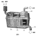
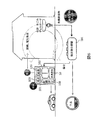
- FIG. 5 is a cutaway perspective view illustrating a configuration example of the hydrogen generation tank 10, the control tank 101, and the culture tank 102 of the power generation system of FIG. Explanatory drawing of the household power generation system using the power generation system of FIG.
- the hydrogen production apparatus of the present invention is an apparatus that has water, a photocatalyst, and a light source that emits light that causes photocatalysis to the photocatalyst, and generates hydrogen by decomposing water using the photocatalyst irradiated with light.
- a liquid light source is used as the light source.
- the liquid light source can be freely shaped by its fluidity. It can be changed to be close to or in contact with the photocatalyst. Therefore, the photocatalyst is not positioned in the shadow of the concavo-convex structure or the like with respect to the light source, and the entire surface of the photocatalyst can be irradiated with light.
- a light source including any one of a luminescent organism dispersed in a liquid, a phosphorescent material dispersed in a liquid, and a chemiluminescent solution can be used.
- a liquid light source can be directly brought into contact with the photocatalyst, so that water contact with the photocatalyst and light irradiation can be realized simultaneously.
- the photocatalyst can be placed on the inner wall of the hydrogen generation tank.
- the hydrogen generation tank may constitute a flow path through which a liquid light source flows.
- the surface area of the photocatalyst can be increased by arranging the photocatalyst on the unevenness formed on the inner wall of the hydrogen generation tank or the inner wall of the flow path.
- the surface area can be particularly increased by making the irregularities into pleated irregularities, for example, pleated irregularities imitating animal intestinal irregularities. It is also possible to carry the photocatalyst on the adherend having an uneven structure and fix the adherend to the inner wall of the hydrogen generation tank or the inner wall of the flow path.
- the photocatalyst may be provided as a photocatalyst layer on the entire inner wall or adherend, or may be arranged in an island shape.
- the photocatalyst layer may be formed of a single photocatalyst material, or may be formed of a material in which particles of the photocatalyst material are dispersed in a material transparent to light emitted from a liquid light source (for example, a resin or an inorganic substance). Also good.
- Some liquid light sources emit light in response to a stimulus, so there is a stimulus generator in the hydrogen generation tank that emits light by applying chemical, physical or electrical stimulation to the liquid light source. You may arrange. Specifically, a stirrer that stirs a liquid light source, a heating device that heats a liquid light source, a voltage application device that applies electrical stimulation, or the like can be disposed as a stimulus generator.
- the hydrogen generation tank may have an inlet that takes in a liquid light source from the outside, an outlet that flows out the liquid light source inside, and a hydrogen outlet that takes out the hydrogen generated inside. Good.
- the liquid light source that has stopped emitting light can be taken out from the outlet, and a liquid light source capable of emitting light can be supplied from the inlet.
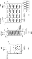
- FIG. 1 (a) has a structure in which a liquid obtained by mixing a liquid light source (hereinafter referred to as a liquid light source 30) and water 40 is stored in a hydrogen generation tank 10.
- a liquid light source 30 hereinafter referred to as a liquid light source 30
- FIG. 1 (a) has a structure in which a liquid obtained by mixing a liquid light source (hereinafter referred to as a liquid light source 30) and water 40 is stored in a hydrogen generation tank 10.
- the photocatalyst 20 is in the form of particles and is dispersed in a liquid mixture of the liquid light source 30 and water 40.
- the particulate photocatalyst 20 contacts the water 40 and is irradiated with light emitted from the liquid light source 30 to decompose the water 40 into hydrogen and oxygen.
- Hydrogen and oxygen are collected from the upper opening of the hydrogen generation tank 10 to separate hydrogen from oxygen.
- the photocatalyst 20 can be arranged in layers or islands on the entire or part of the inner wall of the hydrogen generation tank 10.
- an inflow port and an outflow port for supplying a mixed liquid of the liquid light source 30 and the water 40 may be provided in the hydrogen generation tank, and the liquid light source 30 in a state capable of emitting light may be supplied intermittently or continuously.
- the photocatalyst can be efficiently used by recovering the photocatalyst near the outflow port by a technique such as filtration and supplying it again to the liquid light source 30 supplied from the inflow port.
- the hydrogen production apparatus of FIG. 1B is provided with a flow path 50 through which the liquid light source 30 flows inside the hydrogen generation tank 10 and decomposes into a flow path 60 between the outside of the flow path 50 and the hydrogen generation tank 10.
- the water 40 is configured to flow.
- the channel 50 is made of a material that is transparent to light emitted from the liquid light source 30.
- An adherend (base material) 60 having a concavo-convex structure is disposed on the inner wall of the hydrogen generation tank 10, and a layer of the photocatalyst 20 is formed on the surface of the adherend 60.
- the adherend 60 has a pleated concavo-convex structure simulating the inner wall of the small intestine of a human body, and has a surface area 100 to 1000 times larger than that without the pleated concavo-convex structure.
- the flow path 50 meanders so as to sew between the adherends 60.
- the liquid light source 30 irradiates the photocatalyst 20 on the surface of the adherend 60 having a complicated shape with light through the transparent flow path 50.
- the amount of hydrogen produced is proportional to the surface area of the effective photocatalyst 20, it is possible to produce 100 to 1000 times as much hydrogen in the present invention as compared with the case where there is no unevenness.
- the generated hydrogen and oxygen are collected mainly from the outlet 60b, and hydrogen and oxygen are separated to obtain hydrogen.
- the hydrogen production apparatus in FIG. 1C has a flow path formed inside the hydrogen generation tank 10, an adherend 60 is disposed on the inner wall, and a layer of the photocatalyst 20 is formed on the surface of the adherend 60.
- the adherend 60 is a pleated concavo-convex structure imitating the inner wall of the small intestine of a human body.
- a mixture of the liquid light source 30 and the water 40 is supplied to the inlet 10a of the flow path.
- the liquid light source 30 irradiates the photocatalyst 20 on the surface of the adherend 60 having a complicated shape with light, and the water 40 is decomposed on the surface of the photocatalyst 20 to generate hydrogen and oxygen.
- the produced hydrogen and oxygen are collected mainly from the outlet 10b, and hydrogen and oxygen are separated to obtain hydrogen.
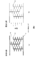
- the shape of the light source can be freely changed, and even the photocatalyst 20 supported by the adherend 60 having a complicated structure is brought close to or in contact with the entire surface to emit light. Can be irradiated. Therefore, as shown in FIG. 2A, the photocatalyst 20 can irradiate light, and even the photocatalyst 20 having a complicated shape has no shadowed portion of the light source and can be irradiated with light.
- a fixed light source is used as shown in FIG. 2 (b)
- light can be emitted only from the direction in which the light source is arranged.
- the photocatalyst cannot be irradiated with light.
- the liquid light source 30 by using the liquid light source 30, the area of the photocatalyst that can exhibit the photocatalytic action can be greatly increased, and hydrogen can be generated with high efficiency.
- a stimulus generation unit that emits light by applying a chemical, physical, or electrical stimulus to a liquid light source may be disposed.
- a stirrer that stirs a liquid light source, a heating device that heats a liquid light source, a voltage application device that applies electrical stimulation, or the like can be disposed as a stimulus generator.
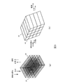
- the shape of the adherend 60 in the hydrogen generation tank 10 is not limited to the shapes shown in FIGS. 1B and 1C, but is a mesh-like adherend 60 as shown in FIG. Alternatively, a cylindrical adherend 60 can be used.
- a photocatalyst By attaching a photocatalyst to the outer periphery and inner wall of these adherends 60 and allowing the liquid light source 30 and water 40 to pass through, the water can be decomposed by the photocatalyst to generate hydrogen.
- Liquid light source 30 a light source that does not require electric power for light output is used.
- a light emitting organism mixed (dispersed) in a liquid a powdered phosphorescent material mixed (dispersed) in a liquid, and Any of the chemiluminescent solutions can be used.
- a light source that emits light having a wavelength that causes the photocatalyst 20 to produce a photocatalytic action is used.
- the wavelength necessary for the action of the photocatalyst 20 depends on the material of the photocatalyst, but generally, the shorter the wavelength, the higher the efficiency. It is desirable to have a peak.
- the liquid light source can store light so that it can emit light having an intensity necessary for decomposing water by the photocatalyst. Adjust the type, concentration and amount of materials, luminescent organisms and chemiluminescent solutions.
- the relationship between the light intensity and the amount of hydrogen produced by the reaction of the photocatalyst is proportional in the range where the light intensity is weak, but when the light intensity increases, the hydrogen produced by the reaction of the photocatalyst. Is proportional to the (1/2) th power of the light intensity. Therefore, when the light intensity is increased to some extent, it is more effective to increase the surface area of the photocatalyst than to increase the light intensity.
- the amount of hydrogen produced is proportional to the surface area of the photocatalyst.
- the present invention is superior to using a fixed light source in that the liquid light source can be used to increase (control) the intensity of the light source and to increase the surface area of the photocatalyst.
- the liquid light source 30 is a mixture of luminescent organisms in a liquid
- luminescent bacteria and luminescent plankton can be used as the luminescent organisms. Since the diameter of the luminescent bacteria is as small as 1 to 2 ⁇ m and the diameter of the luminescent plankton is as small as 40 ⁇ m to 1 mm, when both are mixed with the liquid and used as the liquid light source 30, the liquid has excellent fluidity. Moreover, since it can be cultured easily if there is appropriate nutrition at room temperature, it is easy to handle. There is also an advantage that it is easy to use because of low toxicity to the human body.
- the unevenness of the adherend 60 is designed so that the width of the gap is at least 10 times the diameter of the luminescent organisms used so that the luminescent organisms of the liquid light source 30 can pass through the gaps of the irregularities.
- the luminescent bacteria are known luminescence showing strong luminescence and wavelength such as Photobacterium phosphoreum of Photobacterium genus emitting blue light with luminescence wavelength 475 nm, Vibrio fischeri Y-1 of Vibrio genus emitting light yellow of 535 nm.
- One or more of bacteria can be used.
- a protein that is recombined by genetic recombination or the like can be used in a protein present in bacteria (lumazine protein (Lump) for photobacterium phosphoreum, YFP protein for Vibrio fischeri Y-1).
- Jacochu can be used for animals, and scallops can be used for plants.
- Jakouchu is a transparent unicellular organism in the shape of a peach about 1 mm in diameter.
- the luminescence intensity can be increased by increasing the concentration (density) of the luminescent plankton in the liquid light source 30, so that the amount of hydrogen produced increases.
- the concentration (density) since the luminescent bacteria have a characteristic that they do not emit light unless the density of the bacteria is more than a certain level, it is desirable to set the concentration (density) to 5% by weight or more. However, if the concentration becomes too high, the viscosity of the liquid light source 30 increases and the fluidity decreases, so the concentration is desirably 90% by weight or less.
- the emission intensity depends on chemical, physical and electrical stimuli such as salt concentration, oxygen concentration, temperature, and agitation of the liquid light source 30, and the emission intensity is increased by these stimuli. Therefore, it is possible to stimulate the luminescent organism.
- the solvent (liquid) for mixing (dispersing) luminous bacteria and plankton is selected according to the luminous bacteria and plankton.
- the luminescent bacteria and plankton are marine, saline is used as a solvent, and when they are fresh water, water is used.
- the salt concentration is preferably set to 3 to 5%, which is a general seawater concentration. Since the emission intensity changes, the salt concentration is set so that the necessary emission intensity can be obtained.
- phosphorescent material As an example of the phosphorescent material, zinc sulfide (ZnS system) or strontium aluminate (SrAl 2 O 4 system) can be used. Those having an average particle diameter of 0.1 to 30 ⁇ m can be used. In this case, the afterglow time is about 30 minutes to 2 hours.
- ZnS system zinc sulfide
- strontium aluminate strontium aluminate
- a sulfide phosphor can be used as a phosphorescent material.
- CaS purple blue light emission
- CaSrS Bi (blue light emission)
- ZnS Cu (green light emission)
- ZnCdS Cu (yellow to orange light emission), and the like are used. it can.
- a compound represented by MAl 2 O 4 or MAl x O y (where M is selected from the group consisting of Ca, Sr, and Ba) can also be used. If necessary, the compound can be doped with an element. Specifically, among SrAl 2 O 4 : Eu, Dy (emission wavelength 520 nm), Sr 4 Al 14 O 25 : Eu, Dy (emission wavelength 490 nm), CaAl 2 O 4 : Eu, Nd (emission wavelength 440 nm) One or more of these can be used.
- the liquid light source 30 is obtained by making these phosphorescent materials into particles having a particle diameter of 0.1 ⁇ m to several mm and mixing them with a solvent.
- the phosphorescent material is used after being sufficiently irradiated with light in advance and stored.
- the solvent in which the phosphorescent material is dispersed is not particularly limited as long as it has fluidity such as water or oil.
- an additive such as a surfactant may be added to prevent the photocatalyst and the powdery phosphorescent material from adhering to each other.
- chemiluminescent solution When a chemiluminescent solution is used, if it is a liquid itself, it does not have to be mixed with a solvent separately. Moreover, it is also possible to use what mixed (dispersed) the following substances in the solvent or dissolved in the solvent as the chemiluminescent solution.
- green light-emitting fluorescent substance 9,10-bis (phenylethynyl) anthracene ((C 6 H 5 : C) 2 C 14 H 8 ), orange light-emitting fluorescent substance rubrene (5,6,11,12-tetraphenylnaphthacene) ) (C 42 H 28 ), blue-emitting phosphor perylene (C 20 H 22 ), luminol, lophine, lucigenin, and one or more of oxalate esters can be used.
- the solvent for mixing (dispersing) the above substances may be any fluid such as water or oil.
- a solvent in which the substance is dissolved is selected and used as the solvent to be dissolved.
- a basic aqueous solution can be used.
- photocatalyst Any type of photocatalyst can be used as long as it can decompose water into hydrogen and oxygen.
- a luminescent organism as the liquid light source, considering that the life of the luminescent organism is often difficult when the wavelength is shortened to the ultraviolet region, and that the emission wavelength of the luminescent organism is often about 400 to 700 nm, What produces a photocatalytic action by visible light is desirable. In that case, a visible light-responsive artificial photosynthesis type photocatalyst having a two-step excitation mechanism is desirable.
- the water splitting is divided into a hydrogen generating system and an oxygen generating system, and an iodate / iodide (IO 3 ⁇ / I ⁇ ) is an electron carrier between them It is connected by reversible ion pairs such as Fe ions. Accordingly, since the energy of light necessary for each system is reduced, it is possible to use long-wavelength visible light with small energy.
- any material can be used for the photocatalyst of the two-stage excitation mechanism, but a typical example of a combination of a photocatalyst for hydrogen generation and a photocatalyst for oxygen generation is shown below.
- Pt / SrTiO 3 Cr—Ta / WO 3 , Pt / TaON—WO 3 , Pt / StTiO 3 : Rh—BiVO 4 , Pt / StTiO 3 : Rh—WO 3 , Ru / StTiO 3 : Rh—BiVO 4 , Ru One of / StTiO 3 : Rh—WO 3 , Cr—Rh / GaN: ZnO, and BaTaO 2 N—WO 3 , or two or more can be used.
- a method for arranging the photocatalyst 20 on the adherend 60 a method of mixing the particulate photocatalyst 20 with a binder such as a resin or an inorganic material, applying or dripping it onto the surface of the adherend 60, and solidifying the EB
- a method of forming a film on the surface of the adherend by vapor deposition such as vapor deposition or sputtering can be used.
- the hydrogen generation amount of the hydrogen production apparatus is calculated as follows.
- Luminous bacteria are used as the liquid light source 30.
- the luminescent bacteria Photobacterium phosphoreum of the genus Photobacterium is used.
- the emission wavelength of this bacterium is 475 nm, and hydrogen and oxygen can be generated from water by using an artificial photosynthesis type photocatalyst having a visible light response.
- a liquid light source having a luminescence intensity of about 0.1 to 5 W / m 2 can be produced.
- the photocatalyst 20 uses a two-step excitation mechanism type artificial photosynthesis photocatalyst capable of reacting at an emission wavelength of 475 nm, specifically, ZrO 2 / TaON (hydrogen generation catalyst) each carrying platinum (Pt) nanoparticles.
- WO 3 catalyst for oxygen generation
- sodium iodide is used as a redox reagent.
- the photocatalyst 20 is arranged in a layered manner on the adherend surface having innumerable pleats formed inside the tube.
- the hydrogen generation tank 10 has a structure as shown in FIG. 1B in which the flow path of the liquid light source 30 and the flow path of water to be decomposed are separated.
- the volume of the liquid light source 30 is about 10 L
- the surface area of the photocatalyst 20 is 20000 m 2 (ten tennis courts).
- the hydrogen production amount in this configuration was obtained by calculation, and it was confirmed that the maximum hydrogen production rate was 100 to 500 L / h, and a practical hydrogen amount could be produced.
- This calculation example is an example of the present invention and does not limit the structures of the liquid light source 30, the photocatalyst 20, the adherend 60, and the like.
- the hydrogen production apparatus of the first embodiment is configured to include only the hydrogen generation tank 10, but further includes an adjustment tank that adjusts the liquid light source to a state capable of emitting light and flows into the inlet.
- the adjustment tank includes a control tank, and when the liquid light source is a light source using a luminescent organism, the control tank includes an adjustment unit that adjusts the temperature or salt concentration of the liquid light source, and a liquid light source.
- the control tank includes an adjustment unit that adjusts the temperature or salt concentration of the liquid light source, and a liquid light source.
- the control tank includes a light irradiation unit that irradiates the liquid light source with light and stores the light before supplying the hydrogen generation tank.
- a stimulus generating unit that starts chemical luminescence by applying chemical, physical, or electrical stimulation to a liquid light source can be disposed in the control device.
- the adjustment tank includes a culture tank for cultivating the luminescent organism. Therefore, since a luminescent organism can be cultured, the quantity which supplies a luminescent organism from the outside can be reduced or made zero.
- the light source can be reused by adjusting the liquid light source, which has stopped emitting light in the hydrogen generation tank, to return to the adjustment tank and emit light again.
- the circulation mechanism detects that the liquid light source in the flow path of the hydrogen generation tank is not emitting light, or when a predetermined time has elapsed after flowing into the flow path, the light emission is almost complete. It can be determined that the process has been completed and returned to the adjustment tank.
- a microbial decomposition tank for microbial decomposition of waste water can be connected to the above-described culture tank.
- the microbial decomposition tank supplies at least one of organic substances and gas generated by microbial decomposition to the culture tank. Thereby, the nutrient required for culture
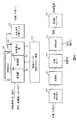
- FIG. 4 shows an example of the overall configuration of a power generation system using a hydrogen production apparatus
- FIG. 5 shows a partial configuration example around the hydrogen generation tank 10.
- This power generation system uses the hydrogen production apparatus described in the first embodiment, and uses a liquid light source 30 in which a luminescent organism is mixed in a solvent.
- a control tank 101 and a culture tank 102 are sequentially arranged as an adjustment tank 111 in the preceding stage of the hydrogen generation tank 10.
- a circulation mechanism 103 that circulates the liquid light source 30 of the hydrogen generation tank 10 to the culture tank 102 is connected to the hydrogen generation tank 10 and the culture tank 102.
- an adjustment unit that adjusts the temperature or salt concentration of the liquid light source 30, an oxygen supply unit that supplies oxygen to the liquid light source 30, and chemical, physical, or electrical stimulation to the liquid light source 30.
- At least one of the stimulus generators that emit light by applying the light is disposed.
- Luminescent bacteria emit light in two steps: (1) storing a luminescent substrate and (2) luminescence, but the timing is usually different among individual bacteria. In the present invention, the light emission timing of the entire luminescent bacteria can be adjusted by the processing of the control tank 101.
- the control tank 101 is connected to a control unit 112 that controls the operation of the adjustment unit, the oxygen supply unit, or the stimulus generation unit in the control tank 101.
- control tank 101 raises the temperature (20 to 30 ° C.) higher than the culture temperature (10 to 25 ° C.) of the culture tank 102, applies physical stimulation by stirring, and raises the oxygen concentration in the liquid (in the air)
- Oxidized water has an oxygen concentration of 1.5 to 50 times compared to 9.3 milligrams of oxygen per liter and 9.3 milliliters at 20 ° C.), or is given a light stimulus (eg, , Irradiation with light of 410 to 460 nm).
- the culture tank 102 is supplied with a liquid medium (water and salt) and nutrients (organic matter, methane gas, etc.) from the outside.
- a liquid medium water and salt
- nutrients organic matter, methane gas, etc.
- the hydrogen generation tank 10 is provided with a gas outlet 10c for extracting hydrogen gas and oxygen gas, and a hydrogen / oxygen separation filter 105 is attached to the gas outlet 10c.
- a purifier 106, a compressor 107, a hydrogen storage cylinder 108, a fuel cell 109, and a converter 110 are connected to the hydrogen / oxygen separation filter 105 in this order.
- This power generation system generates hydrogen and oxygen in the hydrogen generation tank 10 as described in the first embodiment.
- the hydrogen / oxygen separation filter 105 separates hydrogen from oxygen, and the purifier 106 purifies the hydrogen.
- the highly purified hydrogen is compressed by the compressor 107 and stored in the hydrogen storage cylinder 108.
- the fuel cell 109 Under the control of a fuel cell control device (not shown), the fuel cell 109 receives supply of hydrogen from the hydrogen storage cylinder 108 and takes in air (oxygen) from the outside air to generate power.
- the generated electricity is converted from direct current to alternating current by the converter 110, transformed as necessary, and supplied to a load such as a household electric appliance.
- the liquid light source 30 that has finished emitting light in the hydrogen generation tank 10 is returned to the culture tank 102 when the circulation mechanism 103 detects the end of light emission or when a certain time has passed.
- the luminescent bacteria and the luminescent plankton which are luminescent organisms, can be cultured in the culture tank 102 until they can emit light again.
- the cultured liquid light source 30 is supplied to the control tank 101, and under the control of the control unit 112, in the control tank 101, temperature adjustment, oxygen supply liquid, chemical, physical or electrical stimulation is performed as necessary.
- the hydrogen generation tank 10 is adjusted so that it can emit light, and is supplied to the hydrogen generation tank 10 from the inlet 10a. Thereby, the liquid light source 30 irradiates the photocatalyst 20 with light in the hydrogen generation tank 10, and the photocatalyst 20 decomposes water to generate hydrogen and oxygen.
- the power generation system can cultivate luminescent bacteria and luminescent plankton, which are luminescent organisms, in the apparatus instead of constantly adding them from the outside. Can provide a system. Further, since water is decomposed by the photocatalyst, CO 2 is not generated, and power generation with a small environmental load can be performed.
- the microbial decomposition tank 201 which carries out the microbial decomposition of the organic waste contained in waste water is arrange
- a circulating power generation system that uses household wastewater as an energy source.
- raw garbage discharged from the home is pulverized by a disposer (pulverizer), supplied to the microbial decomposition tank 201, and decomposed by microorganisms.
- a disposer supplied to the microbial decomposition tank 201, and decomposed by microorganisms.
- At least one of the organic matter decomposed in the microbial decomposition tank 201 and the methane gas generated by the decomposition by the microorganisms is supplied to the culturing tank 102 as a nutrient for luminescent bacteria and luminescent plankton, and is used for culturing.
- Hydrogen generated in the hydrogen generation tank 10 can be stored in the hydrogen storage cylinder 108 and can be converted into electricity by the fuel cell 109 at a timing when electricity is required. This electricity is converted into an alternating voltage of a household power source by the converter 110 and supplied to a load (lighting, charge product) in the home. Further, the hydrogen in the hydrogen storage cylinder 108 can be used not only as a home fuel cell 109 but also as an automobile fuel such as an automobile fuel cell.
- the power generation system of FIG. 6 uses domestic waste, which is renewable energy, and can realize a highly sustainable society as clean energy with low CO 2 emissions.
- 10 hydrogen generation tank
- 20 photocatalyst
- 30 liquid light source
- 40 water
- 50 flow path of liquid light source
- 60 flow path of water to be decomposed
- 101 control tank
- 102 culture tank 103: circulation mechanism
- 105 hydrogen / oxygen separation filter
- 106 purifier
- 107 compressor
- 108 hydrogen storage cylinder
- 109 household fuel cell
- 110 converter
- 201 microbial decomposition tank
Landscapes
- Chemical & Material Sciences (AREA)
- Engineering & Computer Science (AREA)
- Life Sciences & Earth Sciences (AREA)
- Health & Medical Sciences (AREA)
- Organic Chemistry (AREA)
- Wood Science & Technology (AREA)
- Zoology (AREA)
- Bioinformatics & Cheminformatics (AREA)
- Genetics & Genomics (AREA)
- Biotechnology (AREA)
- General Health & Medical Sciences (AREA)
- General Engineering & Computer Science (AREA)
- Biochemistry (AREA)
- Microbiology (AREA)
- Biomedical Technology (AREA)
- Sustainable Development (AREA)
- General Chemical & Material Sciences (AREA)
- Molecular Biology (AREA)
- Chemical Kinetics & Catalysis (AREA)
- Tropical Medicine & Parasitology (AREA)
- Medicinal Chemistry (AREA)
- Virology (AREA)
- Combustion & Propulsion (AREA)
- Manufacturing & Machinery (AREA)
- Sustainable Energy (AREA)
- Electrochemistry (AREA)
- Inorganic Chemistry (AREA)
- Oil, Petroleum & Natural Gas (AREA)
- Materials Engineering (AREA)
- Catalysts (AREA)
- Apparatus Associated With Microorganisms And Enzymes (AREA)
- Micro-Organisms Or Cultivation Processes Thereof (AREA)
- Fuel Cell (AREA)
Description
本発明は、水と光触媒と光を用いて水素を発生する装置に関する。
現在、水素は石油精製、化学製品、工業製品、燃料電池など多岐にわたり利用されている。特に、水素を利用した燃料電池は、反応過程で水しか生成されないクリーンなエネルギー源として期待されている。しかし、水素は天然にはほとんど存在しないため、化石燃料を用いた水蒸気改質、部分改質ならびに接触改質や、コークス炉ガスから水素を分離する方法や、水の電気分解などの方法により人工的に製造されている。これらの水素製造方法は、化石燃料の燃焼やCO2の大量排出を伴うため、環境負荷が大きいという課題がある。
一方、化石燃料の燃焼やCO2排出が小さい水素生成方法として、特許文献1のように、水を光触媒の表面に接触させ、光触媒の表面に光触媒作用に必要な波長と強度をもつ光を照射することにより、水を分解し、水素と酸素を発生させる方法も提案されている。
光触媒を利用した水素生成装置の水素の発生量は、光の波長や強度、ならびに光触媒の効率に加え、光触媒の表面積に依存する。水と接触し、光が照射されている光触媒の面積が広いほど水素の発生量が増加する。
光触媒自体の表面積は、光触媒を支持する基材の表面に凹凸を形成したり、光触媒自体を粉末状にすることにより大きくできる。しかし、光触媒を支持する基材が複雑な凹凸形状である場合、太陽光、ランプおよびLEDなどの固定光源に対して影になる部分が生じるため、影になる部分の光触媒には光を照射することができない。そのため、基材を複雑な凹凸形状にして光触媒の表面積を拡大したとしても、その全面に光を照射することが困難であるため、水素の発生に有効な表面積を大きくできない。
本発明の目的は、複雑な構造を有する光触媒の表面全体に光を照射することができる水素製造装置を提供することにある。
上記目的を達成するために、本発明の水素製造装置は、水と、光触媒と、光触媒に光触媒作用を生じさせる光を照射する光源とを有し、光を照射された光触媒により水を分解して水素を発生する装置であって、光源として液体状の光源を用いる。これにより、液体状の光源を光触媒に近接または接触させ、液体状の光源からの光を光触媒に照射することができるため、複雑な形状の光触媒の表面全体に光を照射できる。
本発明では、液体状の光源を用いることにより、光触媒の構造が複雑であっても、光源を近接または接触させることができるため、光源に対して影になる部分が生じるのを防ぐことができ、水素の発生効率を向上させることができる。
以下、本発明の一実施の形態の水素製造装置について具体的に説明する。
本発明の水素製造装置は、水と、光触媒と、光触媒に光触媒作用を生じさせる光を照射する光源とを有し、光を照射された光触媒により水を分解して水素を発生する装置であって、光源として液体状の光源を用いる。
これにより、光触媒の表面積を広げるために、複雑な凹凸構造の表面に光触媒を配置した場合や、光触媒を粒子状とした場合であっても、液体状の光源はその流動性により形状を自由に変えて光触媒に近接または接触できる。したがって光触媒が、光源に対して凹凸構造等の影に位置することがなく、光触媒の表面全体に光を照射することができる。よって、光触媒の有効表面積を拡大することができるため、光触媒によって水を効率よく分解でき、実用化可能なレベルで水素が製造できる。なお、水の分解により酸素も生成されるため、本発明の装置を酸素生成装置として用いることも可能である。
液体状の光源は、液体に分散された発光生物、液体に分散された蓄光材、および、化学発光溶液のうちいずれかを含むものを用いることができる。これらが水を含有している場合には、液体状の光源を直接光触媒に接触させることで、光触媒への水の接触と光の照射とを同時に実現することができる。また、液体状の光源と分解すべき水とを、光源の光に対して透明な部材により分離し、光触媒に、分解すべき水のみを接触させる構成とすることも可能である。この透明な部材により、液体状の光源が流れる液体光源用流路と、光触媒に接触するように水が流れる水用流路を構成することも可能である。
光触媒は、水素発生槽の内壁に配置することが可能である。水素発生槽は、液体状の光源が流れる流路を構成していてもよい。光触媒は、水素発生槽の内壁または流路の内壁に形成した凹凸に配置することにより光触媒の表面積を大きくすることができる。凹凸は、ひだ状の凹凸、例えば動物の腸の凹凸を模したひだ状の凹凸にすることにより、表面積を特に大きくすることができる。また、光触媒を凹凸構造の被着体に坦持させ、被着体を水素発生槽の内壁または流路の内壁に固定することも可能である。
光触媒は、内壁や被着体の全面に光触媒層として備えられていてもよいし、島状に配置されていてもよい。光触媒層は、光触媒材料単体で形成されていてもよいし、光触媒材料の粒子を、液状光源の発する光に対して透明な材料(例えば、樹脂や無機物)に分散させた材料で形成されていてもよい。
光触媒として、粒子状のものを用い、水とともに、液体状の光源に混合することも可能である。粒子状にすることにより、光触媒の表面積を増大させることができる。
液体状の光源の中には、刺激を受けて発光するものもあるため、水素発生槽内に、液体状の光源に化学的、物理的または電気的な刺激を与えて発光させる刺激発生部を配置してもよい。具体的には、液体状の光源を撹拌する撹拌装置、液体状の光源を加熱する加熱装置、または、電気刺激を与える電圧印加装置等を刺激発生部として配置することができる。
水素発生槽は、外部から液体状の光源を内部に取り込む流入口と、内部の液体状の光源を流出する流出口と、内部で発生した水素を外部に取り出す水素取り出し口とを有する構成としてもよい。これにより、発光しなくなった液体状の光源を流出口から外部に取り出し、発光可能な状態の液体状の光源を流入口から供給できる。
(第1の実施形態)
以下、第1の実施形態の水素製造装置を図面を用いて具体的に説明する。
以下、第1の実施形態の水素製造装置を図面を用いて具体的に説明する。
図1(a)、(b)、(c)は、それぞれ水素製造装置の全体構成を示すブロック図である。
図1(a)の水素製造装置は、水素発生槽10の内部に、液体状の光源(以下、液体光源30と呼ぶ)と水40とを混合した液体を蓄えた構造である。光触媒20は、粒子状であり、液体光源30と水40との混合液体に分散されている。この構成では、粒子状の光触媒20は、水40に接触するとともに、液体状の光源30が発する光を照射され、水40を水素と酸素に分解する。水素と酸素は、水素発生槽10の上部開口から収集され、水素を酸素から分離する。光触媒20を粒子状にすることにより、その表面積を、バルク状のものと比較して1000~10000倍にまで拡大することが可能となる。
なお、図1(a)の構造において、水素発生槽10の内壁の全面または一部に光触媒20を層状または島状に配置することも可能である。また、水素発生槽に、液体光源30と水40の混合液体を供給する流入口と流出口を設けて、発光可能な状態の液体光源30を断続的または連続的に供給してもよい。この場合、光触媒は、流出口付近でろ過等の手法により回収し、流入口から供給する液体光源30に再び供給することにより、光触媒を効率よく利用することができる。
図1(b)の水素製造装置は、水素発生槽10の内部に、液体光源30を流す流路50を設け、流路50の外側と水素発生槽10の間の流路60に、分解すべき水40を流すように構成されている。流路50は、液体光源30が発する光に対して透明な材料で構成されている。水素発生槽10の内壁には、凹凸構造の被着体(基材)60が配置され、被着体60の表面に光触媒20の層が形成されている。被着体60は、人体の小腸の内壁を模したひだ状の凹凸構造になっており、ひだ状の凹凸構造でないものに比べ100~1000倍に表面積が大きい。流路50は、被着体60の間を縫うように蛇行している。
流路50の流入口50aから液体光源30を供給し、流出口50bから排出しながら、分解すべき水を流路60の流入口60aから供給し、流出光60bから排出する。液体光源30は、複雑な形状をした被着体60の表面の光触媒20に、透明な流路50を通して、光を照射する。液体光源30により光が照射された光触媒20表面では、光触媒の作用により水が分解され水素と酸素が生成される。生成される水素の量は、有効な光触媒20の表面積に比例するため、本発明では凹凸がない場合と比較して100~1000倍の水素を生成することが可能となる。発生した水素と酸素は、主に流出口60bから収集され、水素と酸素とを分離して、水素を取得する。
図1(c)の水素製造装置は、水素発生槽10の内部に流路を形成し、その内壁に被着体60を配置し、被着体60の表面に光触媒20の層を形成している。被着体60は、人体の小腸の内壁を模したひだ状の凹凸構造である。流路の流入口10aには、液体光源30と水40の混合物を供給する。液体光源30は、複雑な形状をした被着体60の表面の光触媒20に光を照射し、光触媒20表面では、水40が分解されて水素と酸素が生成される。生成された水素と酸素は、主に流出口10bから収集され、水素と酸素とを分離して、水素を取得する。
本実施形態では、液体光源を用いるため光源が自由に形状を変えることができ、複雑な構造の被着体60に支持された光触媒20であっても近接または接触して、その全体に光を照射することができる。よって、図2(a)に光触媒に光を照射可能な範囲を示すように、複雑な形状の光触媒20であっても光源の影になる部分がなく、全体に光を照射できる。これに対し、図2(b)のように固定された光源を用いた場合には、光源の配置された方向からしか光を照射できないため、光源に対して被着体の影になる部分の光触媒には光を照射できない。本発明では、液体光源30を用いることにより、光触媒作用を発揮できる光触媒の面積を大幅に増大させることができ、高効率に水素を発生することができる。
水素発生槽10内には、液体状の光源に化学的、物理的または電気的な刺激を与えて発光させる刺激発生部を配置してもよい。具体的には、液体状の光源を撹拌する撹拌装置、液体状の光源を加熱する加熱装置、または、電気刺激を与える電圧印加装置等を刺激発生部として配置することができる。
また、水素発生槽10内の被着材60の形状は、図1(b)、(c)の形状に限定されるものではなく、図3(a)のように網目状の被着材60や、筒状の被着材60を用いることも可能である。これらの被着材60の外周や内壁に光触媒を付着させ、液体光源30と水40を通過させることにより、水を光触媒により分解して水素を発生させることができる。
<<液体光源30>>
液状光源としては、光出力のために電力を必要としないものを用い、例えば、発光生物を液体に混合(分散)したもの、粉末状の蓄光材料を液体に混合(分散)したもの、および、化学発光溶液のうちいずれかを用いることができる。液体光源30は、光触媒20に光触媒作用を生じさせる波長の光を出射するものを用いる。光触媒20の作用に必要な波長は、光触媒の材料に依存するが、一般的に、波長が短いほど効率が高くなるため、液体光源の発光波長は、可視光以下、より好ましくは500nm以下に発光ピークをもつことが望ましい。
液状光源としては、光出力のために電力を必要としないものを用い、例えば、発光生物を液体に混合(分散)したもの、粉末状の蓄光材料を液体に混合(分散)したもの、および、化学発光溶液のうちいずれかを用いることができる。液体光源30は、光触媒20に光触媒作用を生じさせる波長の光を出射するものを用いる。光触媒20の作用に必要な波長は、光触媒の材料に依存するが、一般的に、波長が短いほど効率が高くなるため、液体光源の発光波長は、可視光以下、より好ましくは500nm以下に発光ピークをもつことが望ましい。
また、光触媒20は、その種類により光触媒作用を発揮するのに必要な光の強度がきまっているので、液体光源は、光触媒により水を分解するのに必要な強度の光を出射できるように、蓄光材料、発光生物や化学発光溶液の種類、濃度および量等を調整する。
なお、一般に、光の強度と光触媒の反応により生成される水素の量の関係は、光の強度が弱い範囲では比例関係にあるが、光の強度が高くなると、光触媒の反応により生成される水素の量は、光の強度の(1/2)乗に比例する。そのため、ある程度以上光の強度が強くなると、光の強度を上げるよりも、光触媒の表面積を上げることが有効となる。水素生成量は、光触媒の表面積に比例する。本発明は、液体光源を利用することにより、光源の強度を高める(制御できる)とともに、光触媒の表面積を拡大できる点で固定された光源を用いるものより優れている。
<発光生物>
液体光源30として、発光生物を液体に混合したものを用いる場合、発光生物としては、発光バクテリアや発光プランクトンを用いることができる。発光バクテリアの径は1~2μm、発光プランクトンの径は40μmから1mmと小さいため、いずれも液体に混合して液体光源30とした場合に、流動性に優れた液体になる。また、室温で適度な栄養があれば簡単に培養できるため、取り扱いが容易である。人体への毒性も低いため利用しやすいというメリットもある。
液体光源30として、発光生物を液体に混合したものを用いる場合、発光生物としては、発光バクテリアや発光プランクトンを用いることができる。発光バクテリアの径は1~2μm、発光プランクトンの径は40μmから1mmと小さいため、いずれも液体に混合して液体光源30とした場合に、流動性に優れた液体になる。また、室温で適度な栄養があれば簡単に培養できるため、取り扱いが容易である。人体への毒性も低いため利用しやすいというメリットもある。
被着体60の凹凸は、凹凸の隙間を液体光源30の発光生物が通過できるように、隙間の幅が使用する発光生物の径の10倍以上になるよう設計することが望ましい。
具体的には、発光バクテリアは、発光波長475nmの青色に発光するPhotobacterium属のPhotobacterium phosphoreumや、発光波長535nmの黄色に発光するVibrio属のVibrio fischeri Y-1など強い発光や波長を示す公知の発光バクテリア(約19種類)等のうちの1種以上を用いることができる。また、これらの公知の発光バクテリアに加え、新規の発光バクテリアや遺伝子組み換えを行った発光バクテリアを用いることも可能である。例えば、バクテリアの中に存在するタンパク質(photobacterium phosphoreumではルマジンタンパク質(Lump)、Vibrio fischeri Y-1ではYFPタンパク質)を遺伝子組み換え等で組み換えたものを用いることができる。
具体的な発光プランクトンの例としては、動物性ではヤコウチュウ、植物性ではウズオビムシを用いることができる。ヤコウチュウは,直径1mmほどの桃の形をした透明な単細胞生物である。
発光プランクトンを用いる場合、液体光源30における発光プランクトンの濃度(密度)を大きくすることで発光強度を高めることができるため、生成される水素量が増加する。一方、発光バクテリアは、バクテリアの密度がある程度以上でなければ発光しないという特性があるため、濃度(密度)を5重量%以上に設定することが望ましい。ただし、濃度が高くなりすぎると、液体光源30の粘度が増し、流動性が低下するため、濃度は90重量%以下であることが望ましい。
また、発光強度は、濃度(密度)以外にも、液体光源30の塩分濃度、酸素濃度、温度、撹拌など化学、物理的・電気的刺激などに依存し、これらの刺激により発光強度を高めることができるため、発光生物に刺激を与えることも可能である。
発光バクテリアやプランクトンを混合(分散)する溶媒(液体)は、発光バクテリアやプランクトンに応じて選択する。例えば、発光バクテリアやプランクトンが海洋性の場合は溶媒として食塩水を、淡水性の場合は水を用いる。食塩水を用いて発光バクテリアを培養する場合には、塩分濃度を一般的な海水の濃度である3~5%に設定することが好ましいが、液体光源30として利用する場合には、塩分濃度により発光強度が変化するため、必要な発光強度が得られる塩分濃度に設定する。
<蓄光材>
蓄光材としては、一例としては、硫化亜鉛(ZnS系)やアルミン酸ストロンチウム(SrAl2O4系)を用いることができる。これらの平均粒子径としては、0.1~30μmのものを用いることができる。この場合、残光時間は、約30分から2時間程度である。
蓄光材としては、一例としては、硫化亜鉛(ZnS系)やアルミン酸ストロンチウム(SrAl2O4系)を用いることができる。これらの平均粒子径としては、0.1~30μmのものを用いることができる。この場合、残光時間は、約30分から2時間程度である。
また、蓄光材として、硫化物蛍光体を用いることが可能である。具体的には、CaS:Bi(紫青色発光)、CaSrS:Bi(青色発光)、ZnS:Cu(緑色発光)、ZnCdS:Cu(黄色~橙色発光)等のうちの1種類以上を用いることができる。
蓄光材として、MAl2O4もしくはMAlxOyで表される化合物(ただし、Mは、Ca、Sr、Baからなる群から選択されたもの)を用いることもできる。必要に応じて、この化合物に元素をドープすることも可能である。具体的には、SrAl2O4:Eu,Dy(発光波長520nm)、Sr4Al14O25:Eu,Dy(発光波長490nm)、CaAl2O4:Eu,Nd(発光波長440nm)のうちの1種類以上を用いることができる。
これらの蓄光材を粒径0.1μm~数mmの粒子状にし、溶媒に混合することにより、液体光源30が得られる。蓄光材にはあらかじめ十分に光照射を行って、蓄光させてから用いる。
液体光源とするために、蓄光材を分散させる溶媒は、水やオイルなど流動性があるものであればよく、特に限定されるものではない。また、光触媒と粉末状の蓄光材料の付着を防止するために、表面活性剤などの添加剤を加えてもよい。
<化学発光溶液>
化学発光溶液を用いる場合は、それ自体が液体である場合には、別途溶媒に混合しなくてもよい。また、以下の物質を溶媒に混合(分散)したもの、または、溶媒に溶解したものを化学発光溶液として用いることも可能である。例えば、緑色発光蛍光物質9,10-ビス(フェニルエチニル)アントラセン((C6H5:C)2C14H8)、橙色発光蛍光物質ルブレン(5,6,11,12-テトラフェニルナフタセン)(C42H28)、青色発光蛍光物質ペリレン(C20H22)、ルミノール、ロフィン、ルシゲニン、および、シュウ酸エステルのうちの1以上を用いることができる。上記物質を混合(分散)させる溶媒としては、水やオイルなど流動性があるものであればよい。また、溶解する溶媒として、上記物質が溶解する溶媒を選択して用いる。例えば、塩基性の水溶液を用いることができる。
化学発光溶液を用いる場合は、それ自体が液体である場合には、別途溶媒に混合しなくてもよい。また、以下の物質を溶媒に混合(分散)したもの、または、溶媒に溶解したものを化学発光溶液として用いることも可能である。例えば、緑色発光蛍光物質9,10-ビス(フェニルエチニル)アントラセン((C6H5:C)2C14H8)、橙色発光蛍光物質ルブレン(5,6,11,12-テトラフェニルナフタセン)(C42H28)、青色発光蛍光物質ペリレン(C20H22)、ルミノール、ロフィン、ルシゲニン、および、シュウ酸エステルのうちの1以上を用いることができる。上記物質を混合(分散)させる溶媒としては、水やオイルなど流動性があるものであればよい。また、溶解する溶媒として、上記物質が溶解する溶媒を選択して用いる。例えば、塩基性の水溶液を用いることができる。
(光触媒)
光触媒の種類は、水を水素と酸素に分解できるものであればいずれでもよい。ただし、液体光源に発光生物を用いる場合、波長が紫外域まで短くなると発光生物の生存が困難になる場合が多いこと、発光生物の発光波長が400~700nm程度のものが多いことを考慮し、可視光によって光触媒作用を生じるものが望ましい。その場合、2段階励起機構をもつ可視光応答の人工光合成型の光触媒が望ましい。2段階光励起(Z-スキーム)型水分解システムは、水の分解が水素生成系と酸素生成系に2分され、その間が電子伝達体であるヨウ素酸・ヨウ化物(IO3-/I-)やFeイオンのような可逆的なイオン対によって連結された形となっている。これより、各系に必要な光のエネルギーが小さくなるため、エネルギーの小さな長波長の可視光も利用することが可能となる。
光触媒の種類は、水を水素と酸素に分解できるものであればいずれでもよい。ただし、液体光源に発光生物を用いる場合、波長が紫外域まで短くなると発光生物の生存が困難になる場合が多いこと、発光生物の発光波長が400~700nm程度のものが多いことを考慮し、可視光によって光触媒作用を生じるものが望ましい。その場合、2段階励起機構をもつ可視光応答の人工光合成型の光触媒が望ましい。2段階光励起(Z-スキーム)型水分解システムは、水の分解が水素生成系と酸素生成系に2分され、その間が電子伝達体であるヨウ素酸・ヨウ化物(IO3-/I-)やFeイオンのような可逆的なイオン対によって連結された形となっている。これより、各系に必要な光のエネルギーが小さくなるため、エネルギーの小さな長波長の可視光も利用することが可能となる。
2段階励起機構の光触媒の材料はいずれでもよいが、代表的な水素生成用光触媒-酸素生成用光触媒の組み合わせの例を以下に示す。
Pt/SrTiO3:Cr-Ta/WO3、Pt/TaON-WO3、Pt/StTiO3:Rh-BiVO4、Pt/StTiO3:Rh-WO3、Ru/StTiO3:Rh-BiVO4、Ru/StTiO3:Rh-WO3、Cr-Rh/GaN:ZnO、および、BaTaO2N-WO3のうちのいずれか、もしくは、2以上を用いることができる。
光触媒20を被着体60上に配置する方法としては、粒子状にした光触媒20を樹脂や無機物等のバインダーに混ぜ、被着体60の表面に塗布や滴下した後、固化させる方法や、EB蒸着やスパッタ等の気相成長法により被着体の表面に成膜する方法を用いることができる。
本実施形態による水素製造装置の水素発生量を計算により求めたところ以下のようになる。液体光源30として発光バクテリアを利用する。発光バクテリアは、Photobacterium属のPhotobacterium phosphoreumを用いる。このバクテリアの発光波長は475nmであり、可視光応答の人工光合成型光触媒を用いれば水から水素と酸素が生成可能である。この発光バクテリアを塩分濃度4%の食塩水で培養すると、発光強度約0.1~5W/m2の液体光源を作製することができる。
光触媒20は、発光波長475nmで反応可能である2段階励起機構型の人工光合成光触媒を用い、具体的には、白金(Pt)ナノ粒子をそれぞれ担持したZrO2/TaON(水素生成用触媒)とWO3(酸素生成用触媒)とを用いる。また、酸化還元試薬としてヨウ化ナトリウムを用いる。
光触媒20は、チューブの内側に無数のひだを形成した被着体表面に層状に配置する。
水素発生槽10は、液体光源30の流路と、分解すべき水の流路とが分離される、図1(b)のような構造のものを用いる。液体光源30の容積は、約10Lとし、光触媒20の表面積は20000m2(テニスコート約10面分)とする。
本構成における水素生成量を計算により求めたところ、最大で水素生成レート100~500L/hであり、実用可能な水素量を生成できることが確認された。なお、この計算例は、本発明の一例であり、液体光源30、光触媒20および被着体60等の構造を限定するものではない。
(第2の実施形態)
第1の実施形態の水素製造装置は、水素発生槽10のみを備えている構成であったが、液体状の光源を発光可能な状態に調整して流入口に流入させる調整槽をさらに有する構成にすることが可能である。例えば、調整槽は、制御槽を含み、制御槽は、液体状の光源が発光生物を利用した光源である場合、液体状の光源の温度または塩分濃度を調整する調整部、液体状の光源に酸素を供給する酸素供給部、および、液体状の光源に化学的、物理的または電気的な刺激を与えて発光させる刺激発生部の少なくとも一つを備えることが可能である。また、液体状の光源が蓄光材を用いた液体である場合には、制御槽は、水素発生槽に供給する前に、液体光源に光を照射し、蓄光させる光照射部を備える構成とする。また、化学発光溶液の場合には、液体状の光源に化学的、物理的または電気的な刺激を与えて、化学発光を開始させる刺激発生部を制御装置に配置することができる。
第1の実施形態の水素製造装置は、水素発生槽10のみを備えている構成であったが、液体状の光源を発光可能な状態に調整して流入口に流入させる調整槽をさらに有する構成にすることが可能である。例えば、調整槽は、制御槽を含み、制御槽は、液体状の光源が発光生物を利用した光源である場合、液体状の光源の温度または塩分濃度を調整する調整部、液体状の光源に酸素を供給する酸素供給部、および、液体状の光源に化学的、物理的または電気的な刺激を与えて発光させる刺激発生部の少なくとも一つを備えることが可能である。また、液体状の光源が蓄光材を用いた液体である場合には、制御槽は、水素発生槽に供給する前に、液体光源に光を照射し、蓄光させる光照射部を備える構成とする。また、化学発光溶液の場合には、液体状の光源に化学的、物理的または電気的な刺激を与えて、化学発光を開始させる刺激発生部を制御装置に配置することができる。
液体状の光源が、液体に分散された発光生物である場合には、調整槽は、発光生物を培養する培養槽を含む構成であることが望ましい。これにより、発光生物を培養できるため、外部から発光生物を供給する量を低減またはゼロにできる。
また、水素発生槽の流出口から流出した液体状の光源を、調整槽に戻す循環機構をさらに有することも好ましい。水素発生槽で発光しなくなった液体状の光源を調整槽に戻して再び発光するように調整することにより、光源を再利用することができる。循環機構は、水素発生槽の流路内の液体状の光源が発光しない状態になったことを検出した場合、または、流路に流入してから所定の時間が経過した場合には発光がほぼ終了したと判断し、調整槽に戻すように構成することができる。
上述の培養槽には、排水を微生物分解する微生物分解槽を連結することができる。微生物分解槽は、微生物分解により生成された有機物およびガスの少なくとも一方を培養槽に供給する。これにより、培養槽に培養に必要な養分を供給できる。
図4に、水素製造装置を用いた発電システムの全体構成の例を、図5に水素発生槽10の周囲の一部構成例を示す。この発電システムは、第1の実施形態で説明した水素製造装置を用い、液体光源30として発光生物を溶媒に混合したものを用いる。水素発生槽10の前段には、調整槽111として、制御槽101と培養槽102とが順に配置されている。
水素発生槽10と培養槽102には、水素発生槽10の液体光源30を培養槽102に循環させる循環機構103を接続している。制御槽101内には、液体光源30の温度または塩分濃度を調整する調整部、液体光源30に酸素を供給する酸素供給部、および、液体光源30に化学的、物理的または電気的な刺激を与えて発光させる刺激発生部のうち少なくとも一つが配置されている。発光バクテリアは、(1)発光基質を蓄える段階と(2)発光の2段階を踏んで発光するが、通常、そのタイミングは個々のバクテリアでバラバラである。本発明では、制御槽101の処理により、発光バクテリア全体の発光タイミングを合わせることができる。なお、制御槽101には、制御槽101内の調整部、酸素供給部または刺激発生部の動作を制御する制御ユニット112が接続されている。
例えば、制御槽101は、温度を培養槽102の培養温度(10~25℃)よりも上昇させる(20~30℃)、撹拌により物理的刺激を加えると共に液中酸素濃度を上昇させる(空気中においた水には平衡状態20℃で1リットル当たりおよび9.3ミリグラムの酸素が溶解しているのに対し、1.5~50倍まで酸素濃度を上げる)、または、光刺激を与える(例えば、410~460nmの光を照射)等の構成とすることができる。
培養槽102には、外部から液体培地(水や塩分)や養分(有機物やメタンガス等)が供給される。
水素発生槽10には、水素ガスおよび酸素ガスを取り出すガス取出口10cが備えられ、ガス取出口10cには、水素/酸素分離フィルタ105が取り付けられている。水素/酸素分離フィルタ105には、純化器106、圧縮器107、水素貯蔵ボンベ108、燃料電池109、変換器110が順に接続されている。
この発電システムは、第1の実施形態で説明したように、水素発生槽10において水素と酸素が発生する。水素/酸素分離フィルタ105は、水素を酸素から分離し、純化器106は、水素を高純度化する。高純度化された水素は、圧縮器107で圧縮され、水素貯蔵ボンベ108に貯蔵される。図示していない燃料電池制御装置の制御下で、燃料電池109は、水素貯蔵ボンベ108から水素の供給を受けるとともに、空気(酸素)を外気から取り込み、発電を行う。発電した電気は、変換器110により直流から交流に変換されるとともに、必要に応じて変圧され、家庭用の電気機器等の負荷に供給される。
また、水素発生槽10で発光を終えた液体光源30は、循環機構103が発光終了を検出するか、もしくは、一定時間が経過したならば、培養槽102に戻す。これにより、培養槽102で発光生物である発光バクテリアや発光プランクトンを再び発光可能な状態まで培養することができる。培養された液体光源30は、制御槽101に供給され、制御ユニット112の制御下で制御槽101において、必要に応じて、温度調整や酸素供給液、化学的、物理的または電気的な刺激が与えられ、水素発生槽10内で発光できる状態に調整されて流入口10aから水素発生槽10に供給される。これにより、液体光源30は、水素発生槽10内で光を光触媒20に照射し、光触媒20は水を分解して水素と酸素を発生する。
このように、第2の実施形態の発電システムは、発光生物である発光バクテリアや発光プランクトンを定常的に外部から追加するのではなく、装置内で培養することができるため、メンテナンスが容易な発電システムを提供できる。また、光触媒により水を分解するため、CO2を発生せず、環境負荷の少ない発電を行うことができる。
また、図6に示すように、住宅から排出される排水管と、第2の実施形態の培養槽102との間に、排水に含まれる有機廃棄物を微生物分解する微生物分解槽201を配置することにより、エネルギー源として家庭等の排水を利用する循環型の発電システムを構成することができる。
図6の発電システムでは、家庭から排出される生ゴミはディスポーザー(粉砕機)で粉砕され、微生物分解槽201に供給され、微生物により分解される。微生物分解槽201で分解された有機物、および、微生物による分解により発生したメタンガスのうち少なくとも一方は、発光バクテリアや発光プランクトンの養分として培養槽102に供給され、培養に利用される。
水素発生槽10で生成された水素は、水素貯蔵ボンベ108に貯蔵することができ、電気が必要なタイミングで燃料電池109により電気に変換できる。この電気は、変換器110により、家庭用電源の交流電圧に変換され家庭内の負荷(照明、電荷製品)に供給される。また、水素貯蔵ボンベ108の水素は、家庭の燃料電池109だけでなく、自動車用の燃料電池等の自動車用燃料としても利用可能である。
図6の発電システムは、再生可能エネルギーである生活廃棄物を利用しており、CO2排出の小さいクリーンエネルギーとして持続可能性の高い社会を実現できるものである。
10:水素発生槽、20:光触媒、30:液体光源、40:水、50:液体光源の流路、60:分解すべき水の流路、101:制御槽、102培養槽、103:循環機構、105:水素/酸素分離フィルタ、106:純化器、107:圧縮器、108:水素貯蔵ボンベ、109:家庭用燃料電池、110:変換器、201:微生物分解槽
Claims (31)
- 水と、光触媒と、前記光触媒に光触媒作用を生じさせる光を照射する光源とを有し、前記光を照射された光触媒により前記水を分解して水素を発生する水素製造装置であって、
前記光源は、液体状の光源であることを特徴とする水素製造装置。 - 請求項1に記載の水素製造装置において、前記液体状の光源は、液体に分散された発光生物、液体に分散された蓄光材、および、化学発光溶液のうちのいずれか一つを含むことを特徴とする水素製造装置。
- 請求項1または2に記載の水素製造装置において、前記液体状の光源が蓄えられた水素発生槽をさらに有し、前記光触媒は、前記水素発生槽の前記内壁に配置されていることを特徴とする水素製造装置。
- 請求項1または2に記載の水素製造装置において、前記液体状の光源を流す流路を備えた水素発生槽をさらに有し、前記光触媒は、前記流路の内壁に配置されていることを特徴とする水素製造装置。
- 請求項1ないし4のいずれか1項に記載の水素製造装置において、前記液体状の光源は、前記水と混合されていることを特徴とする水素製造装置。
- 請求項1に記載の水素製造装置において、前記液体状の光源が蓄えられた水素発生槽をさらに有し、前記光触媒は、前記水素発生槽の前記内壁に配置され、前記水素発生槽内には、前記光触媒に近接して前記液体状の光源を流す液体光源用流路と、前記光触媒に接触するように前記水を流す水用流路とが形成されていることを特徴とする水素製造装置。
- 請求項6に記載の水素製造装置において、前記水素発生槽の前記液体光源用流路と前記水用流路とを隔てる部材を有し、前記部材は、前記液体状の光源の発する光に対して透明であることを特徴とする水素製造装置。
- 請求項1ないし7のいずれか1項に記載の水素製造装置において、前記光触媒は、凹凸が形成された被着体に坦持されていることを特徴とする水素製造装置。
- 請求項1または2に記載の水素製造装置において、前記液体状の光源を蓄える水素発生槽をさらに有し、前記光触媒は、粒子であり、前記水とともに、前記液体状の光源に混合されていることを特徴とする水素製造装置。
- 請求項3ないし9のいずれか1項に記載の水素製造装置において、前記水素発生槽内には、前記液体状の光源に化学的、物理的または電気的な刺激を与えて発光させる刺激発生部が配置されていることを特徴とする水素製造装置。
- 請求項10に記載の水素製造装置において、前記刺激発生部は、前記液体状の光源を撹拌する撹拌装置、前記液体状の光源を加熱する加熱装置、および、電圧印加装置のうちのいずれかを含むことを特徴とする水素製造装置。
- 請求項3、4、6および7のいずれか1項に記載の水素製造装置において、前記水素発生槽は、外部から前記液体状の光源を内部に取り込む流入口と、内部の前記液体状の光源を流出する流出口と、内部で発生した水素を外部に取り出す水素取り出し口とを有することを特徴とする水素製造装置。
- 請求項12に記載の水素製造装置において、前記液体状の光源を発光可能な状態に調整して前記流入口に流入させる調整槽をさらに有することを特徴とする水素製造装置。
- 請求項13に記載の水素製造装置において、前記調整槽は、制御槽を含み、
前記制御槽は、前記液体状の光源の温度または塩分濃度を調整する調整部、前記液体状の光源に酸素を供給する酸素供給部、前記液体状の光源に光を照射する光照射部、および、前記液体状の光源に化学的、物理的または電気的な刺激を与えて発光させる刺激発生部の少なくとも一つを備えることを特徴とする水素製造装置。 - 請求項13または14に記載の水素製造装置において、前記液体状の光源は、液体に分散された発光生物であり、前記調整槽は、前記発光生物を培養する培養槽を含むことを特徴とする水素製造装置。
- 請求項13に記載の水素製造装置において、前記流出口から流出した前記液体状の光源を、前記調整槽に戻す循環機構をさらに有することを特徴とする水素製造装置。
- 請求項16に記載の水素製造装置において、前記循環機構は、前記水素発生槽の前記流路内の前記液体状の光源が発光しない状態になった場合、または、前記流路に流入してから所定の時間が経過した場合に、前記液体状の光源を前記調整槽に戻すことを特徴とする水素製造装置。
- 請求項15に記載の水素製造装置において、排水を微生物分解する微生物分解槽をさらに有し、前記微生物分解槽は、前記培養槽に連結され、前記微生物分解により生成された有機物およびガスの少なくとも一方を前記培養槽に供給することを特徴とする水素製造装置。
- 請求項2に記載の水素製造装置において、前記発光生物は、発光バクテリアおよび発光プランクトンのうち少なくとも一方を含むことを特徴とする水素製造装置。
- 請求項19に記載の水素製造装置において、前記発光バクテリアは、Photobacterium phosphoreumおよびVibrio fischeri Y-1の少なくとも一方を含むことを特徴とする水素製造装置。
- 請求項19に記載の水素製造装置において、前記発光プランクトンは、ヤコウチュウまたはウズオビムシの少なくとも一方を含むことを特徴とする水素製造装置。
- 請求項2に記載の水素製造装置において、前記蓄光材は、硫化亜鉛、アルミン酸ストロンチウム、硫化物蛍光体、および、MAl2O4(ただし、Mは、Ca、SrおよびBaのうちのいずれか)のうちの少なくとも一つを含むことを特徴とする水素製造装置。
- 請求項2に記載の水素製造装置において、前記化学発光溶液は、蛍光体を含むことを特徴とする水素製造装置。
- 請求項1ないし23のいずれか1項に記載の水素製造装置において、前記液体状の光源の発光波長は、500nm以下であることを特徴とする水素製造装置。
- 請求項1ないし24のいずれか1項に記載の水素製造装置において、前記光触媒は、水素生成用光触媒と酸素生成用光触媒の2種類を含むことを特徴とする水素製造装置。
- 液体状の光源を流すための流路を備えた水素発生槽と、前記流路の内壁に備えられた光触媒とを有し、前記液体状の光源から発生した光を前記流路の内壁に照射し、前記光触媒の光触媒作用により水を分解して水素を発生することを特徴とする水素製造装置。
- 請求項26に記載の水素製造装置において、前記水素発生槽は、前記液体状の光源を前記流路に取り込む流入口を有し、前記流入口には、制御槽が接続され、
前記制御槽は、前記液体状の光源の温度または塩分濃度を調整する調整部、前記液体状の光源に酸素を供給する酸素供給部、および、前記液体状の光源に化学的、物理的または電気的な刺激を与えて発光させる刺激発生部のうち少なくとも一つを備えることを特徴とする水素製造装置。 - 水素製造装置と、前記水素製造装置の発生した水素を貯蔵する水素貯蔵部と、前記水素貯蔵部の水素を用いて発電する燃料電池とを有する発電システムであって、前記水素製造装置は、請求項1ないし25のいずれか1項記載の水素製造装置であることを特徴とする発電システム。
- 水素製造装置と、前記水素製造装置の発生した水素を貯蔵する水素貯蔵部と、前記水素貯蔵部の水素を用いて発電する燃料電池と、前記燃料電池の発生した電気を変換して家庭用電源に接続可能にするインバータとを有する発電システムであって、前記水素製造装置は、請求項18に記載の水素製造装置であり、前記微生物分解槽には、家庭からの排水管が接続されていることを特徴とする発電システム。
- 液体状の光源を光触媒に近接または接触させて前記液体状の光源からの光を前記光触媒に照射し、前記光触媒によって水を分解して水素を発生することを特徴とする水素製造方法。
- 請求項30に記載の水素製造方法において、前記液体状の光源は、液体に分散された発光生物、液体に分散された蓄光材、および、化学発光溶液のうちのいずれかを含むことを特徴とする水素製造方法。
Applications Claiming Priority (2)
| Application Number | Priority Date | Filing Date | Title |
|---|---|---|---|
| JP2012-183357 | 2012-08-22 | ||
| JP2012183357A JP2015205778A (ja) | 2012-08-22 | 2012-08-22 | 水素製造装置、水素製造方法および発電システム |
Publications (1)
| Publication Number | Publication Date |
|---|---|
| WO2014030653A1 true WO2014030653A1 (ja) | 2014-02-27 |
Family
ID=50149960
Family Applications (1)
| Application Number | Title | Priority Date | Filing Date |
|---|---|---|---|
| PCT/JP2013/072210 Ceased WO2014030653A1 (ja) | 2012-08-22 | 2013-08-20 | 水素製造装置、水素製造方法および発電システム |
Country Status (2)
| Country | Link |
|---|---|
| JP (1) | JP2015205778A (ja) |
| WO (1) | WO2014030653A1 (ja) |
Cited By (3)
| Publication number | Priority date | Publication date | Assignee | Title |
|---|---|---|---|---|
| CN106399046A (zh) * | 2016-06-04 | 2017-02-15 | 深圳市创宇百川环境科技有限公司 | 利用光能转换快速培养微生物的方法及装置 |
| CN110116988A (zh) * | 2018-02-07 | 2019-08-13 | 中国科学院武汉物理与数学研究所 | 一种光解水产氢的制备方法 |
| JP2022063186A (ja) * | 2020-10-11 | 2022-04-21 | トヨタ自動車株式会社 | 光触媒を用いた水素ガス製造装置 |
Citations (6)
| Publication number | Priority date | Publication date | Assignee | Title |
|---|---|---|---|---|
| JPS62158781A (ja) * | 1985-12-26 | 1987-07-14 | アメリカン・サイアナミド・カンパニ− | 化学発光組成物 |
| JPH0415049A (ja) * | 1990-05-08 | 1992-01-20 | Akihiro Fujimura | 遠隔点状通電実験装置 |
| JP2001086909A (ja) * | 1999-09-21 | 2001-04-03 | Kenichi Tashiro | 照明付き浮き |
| JP2006256901A (ja) * | 2005-03-17 | 2006-09-28 | Nissan Motor Co Ltd | 水素発生装置、水素発生方法及び水素発生システム |
| JP2008050548A (ja) * | 2006-08-25 | 2008-03-06 | Ez Bright Corp | 耐水性が改良された蓄光性蛍光体及びこれを用いた水性塗料又は水性インク |
| JP2012130335A (ja) * | 2010-12-01 | 2012-07-12 | Kitakyushu Foundation For The Advancement Of Industry Science & Technology | 海洋性発光バクテリアの発光制御方法及び海洋性発光バクテリアを用いた環境計測センサー |
-
2012
- 2012-08-22 JP JP2012183357A patent/JP2015205778A/ja active Pending
-
2013
- 2013-08-20 WO PCT/JP2013/072210 patent/WO2014030653A1/ja not_active Ceased
Patent Citations (6)
| Publication number | Priority date | Publication date | Assignee | Title |
|---|---|---|---|---|
| JPS62158781A (ja) * | 1985-12-26 | 1987-07-14 | アメリカン・サイアナミド・カンパニ− | 化学発光組成物 |
| JPH0415049A (ja) * | 1990-05-08 | 1992-01-20 | Akihiro Fujimura | 遠隔点状通電実験装置 |
| JP2001086909A (ja) * | 1999-09-21 | 2001-04-03 | Kenichi Tashiro | 照明付き浮き |
| JP2006256901A (ja) * | 2005-03-17 | 2006-09-28 | Nissan Motor Co Ltd | 水素発生装置、水素発生方法及び水素発生システム |
| JP2008050548A (ja) * | 2006-08-25 | 2008-03-06 | Ez Bright Corp | 耐水性が改良された蓄光性蛍光体及びこれを用いた水性塗料又は水性インク |
| JP2012130335A (ja) * | 2010-12-01 | 2012-07-12 | Kitakyushu Foundation For The Advancement Of Industry Science & Technology | 海洋性発光バクテリアの発光制御方法及び海洋性発光バクテリアを用いた環境計測センサー |
Cited By (5)
| Publication number | Priority date | Publication date | Assignee | Title |
|---|---|---|---|---|
| CN106399046A (zh) * | 2016-06-04 | 2017-02-15 | 深圳市创宇百川环境科技有限公司 | 利用光能转换快速培养微生物的方法及装置 |
| CN110116988A (zh) * | 2018-02-07 | 2019-08-13 | 中国科学院武汉物理与数学研究所 | 一种光解水产氢的制备方法 |
| CN110116988B (zh) * | 2018-02-07 | 2022-06-10 | 中国科学院武汉物理与数学研究所 | 一种光解水产氢的制备方法 |
| JP2022063186A (ja) * | 2020-10-11 | 2022-04-21 | トヨタ自動車株式会社 | 光触媒を用いた水素ガス製造装置 |
| JP7355720B2 (ja) | 2020-10-11 | 2023-10-03 | トヨタ自動車株式会社 | 光触媒を用いた水素ガス製造装置 |
Also Published As
| Publication number | Publication date |
|---|---|
| JP2015205778A (ja) | 2015-11-19 |
Similar Documents
| Publication | Publication Date | Title |
|---|---|---|
| Zeng et al. | Energy-transfer-mediated oxygen activation in carbonyl functionalized carbon nitride nanosheets for high-efficient photocatalytic water disinfection and organic pollutants degradation | |
| Ma et al. | Enhanced photocatalytic bactericidal performance and mechanism with novel Ag/ZnO/g-C3N4 composite under visible light | |
| US10808214B2 (en) | Light emitting diode photobioreactors and methods of use | |
| US20090291485A1 (en) | Apparatus and method for optimizing photosynthetic growth in a photo bioreactor | |
| JP7410581B2 (ja) | 水処理方法および水処理システム | |
| Yeh et al. | Applications of light-emitting diodes in researches conducted in aquatic environment | |
| Virk | History of luminescence from ancient to modern times | |
| CN105008512B (zh) | 光生物反应器 | |
| CN107098459B (zh) | 一种处理高浓度氨氮有机废水的电化学装置及处理方法 | |
| JP2010530757A (ja) | バイオリアクター | |
| US20160166985A1 (en) | Photobioreactor system for air purification by using microalgae | |
| Khoobkar et al. | Performance assessment of a novel pyramid photobioreactor for cultivation of microalgae using external and internal light sources | |
| El-Nahhal et al. | Electricity generation from animal manure | |
| CN105060463A (zh) | 一种光合生物自生o2代替传统曝气的废水处理方法及应用 | |
| WO2014030653A1 (ja) | 水素製造装置、水素製造方法および発電システム | |
| JP6227355B2 (ja) | 水素製造装置 | |
| WO2004048553A1 (ja) | 珪藻を含む液体、珪藻および珪藻の培養方法 | |
| Diekemper et al. | Microwave synthesis of a prominent led phosphor for school students: Chemistry’s contribution to sustainable lighting | |
| JP2012000026A (ja) | 光合成微生物の付着培養方法 | |
| Sharma et al. | Carbon quantum dots embedded trimetallic oxide: Characterization and photocatalytic degradation of Ofloxacin | |
| CN205716906U (zh) | 脉冲式植物补光灯 | |
| JP2009165940A (ja) | 過飽和溶存酸素を含む水の製造方法 | |
| TW202316955A (zh) | 用於集約化養蝦的多功能設備和使用該設備的集約化養蝦系統 | |
| CN105483001A (zh) | 用于空气净化的光生物反应器系统 | |
| JP6165556B2 (ja) | 水素製造装置 |
Legal Events
| Date | Code | Title | Description |
|---|---|---|---|
| 121 | Ep: the epo has been informed by wipo that ep was designated in this application |
Ref document number: 13831614 Country of ref document: EP Kind code of ref document: A1 |
|
| NENP | Non-entry into the national phase |
Ref country code: DE |
|
| 122 | Ep: pct application non-entry in european phase |
Ref document number: 13831614 Country of ref document: EP Kind code of ref document: A1 |
|
| NENP | Non-entry into the national phase |
Ref country code: JP |