WO2014030561A1 - 溶融塩組成物及びその溶融塩組成物を用いた二次電池 - Google Patents
溶融塩組成物及びその溶融塩組成物を用いた二次電池 Download PDFInfo
- Publication number
- WO2014030561A1 WO2014030561A1 PCT/JP2013/071770 JP2013071770W WO2014030561A1 WO 2014030561 A1 WO2014030561 A1 WO 2014030561A1 JP 2013071770 W JP2013071770 W JP 2013071770W WO 2014030561 A1 WO2014030561 A1 WO 2014030561A1
- Authority
- WO
- WIPO (PCT)
- Prior art keywords
- molten salt
- sodium
- salt composition
- bisfluorosulfonylamide
- molten
- Prior art date
Links
Images


Classifications
-
- H—ELECTRICITY
- H01—ELECTRIC ELEMENTS
- H01M—PROCESSES OR MEANS, e.g. BATTERIES, FOR THE DIRECT CONVERSION OF CHEMICAL ENERGY INTO ELECTRICAL ENERGY
- H01M10/00—Secondary cells; Manufacture thereof
- H01M10/05—Accumulators with non-aqueous electrolyte
- H01M10/056—Accumulators with non-aqueous electrolyte characterised by the materials used as electrolytes, e.g. mixed inorganic/organic electrolytes
-
- H—ELECTRICITY
- H01—ELECTRIC ELEMENTS
- H01M—PROCESSES OR MEANS, e.g. BATTERIES, FOR THE DIRECT CONVERSION OF CHEMICAL ENERGY INTO ELECTRICAL ENERGY
- H01M10/00—Secondary cells; Manufacture thereof
- H01M10/05—Accumulators with non-aqueous electrolyte
- H01M10/054—Accumulators with insertion or intercalation of metals other than lithium, e.g. with magnesium or aluminium
-
- H—ELECTRICITY
- H01—ELECTRIC ELEMENTS
- H01M—PROCESSES OR MEANS, e.g. BATTERIES, FOR THE DIRECT CONVERSION OF CHEMICAL ENERGY INTO ELECTRICAL ENERGY
- H01M2300/00—Electrolytes
- H01M2300/0017—Non-aqueous electrolytes
- H01M2300/002—Inorganic electrolyte
- H01M2300/0022—Room temperature molten salts
-
- H—ELECTRICITY
- H01—ELECTRIC ELEMENTS
- H01M—PROCESSES OR MEANS, e.g. BATTERIES, FOR THE DIRECT CONVERSION OF CHEMICAL ENERGY INTO ELECTRICAL ENERGY
- H01M2300/00—Electrolytes
- H01M2300/0017—Non-aqueous electrolytes
- H01M2300/0025—Organic electrolyte
- H01M2300/0045—Room temperature molten salts comprising at least one organic ion
-
- H—ELECTRICITY
- H01—ELECTRIC ELEMENTS
- H01M—PROCESSES OR MEANS, e.g. BATTERIES, FOR THE DIRECT CONVERSION OF CHEMICAL ENERGY INTO ELECTRICAL ENERGY
- H01M2300/00—Electrolytes
- H01M2300/0088—Composites
- H01M2300/0091—Composites in the form of mixtures
-
- Y—GENERAL TAGGING OF NEW TECHNOLOGICAL DEVELOPMENTS; GENERAL TAGGING OF CROSS-SECTIONAL TECHNOLOGIES SPANNING OVER SEVERAL SECTIONS OF THE IPC; TECHNICAL SUBJECTS COVERED BY FORMER USPC CROSS-REFERENCE ART COLLECTIONS [XRACs] AND DIGESTS
- Y02—TECHNOLOGIES OR APPLICATIONS FOR MITIGATION OR ADAPTATION AGAINST CLIMATE CHANGE
- Y02E—REDUCTION OF GREENHOUSE GAS [GHG] EMISSIONS, RELATED TO ENERGY GENERATION, TRANSMISSION OR DISTRIBUTION
- Y02E60/00—Enabling technologies; Technologies with a potential or indirect contribution to GHG emissions mitigation
- Y02E60/10—Energy storage using batteries
Definitions
- the present invention relates to a molten salt composition that becomes an electrolytic solution in a molten state and a secondary battery that uses the molten salt composition as an electrolytic solution.
- Secondary batteries that can store, charge, and discharge electrical energy are widely used for storing power and leveling its supply.
- a lithium ion secondary battery is known as a battery having a high energy density.
- a lithium ion secondary battery has a safety problem because a flammable organic compound liquid is used as an electrolyte.
- lithium as a raw material is concerned about uneven distribution of resources and the amount of resources, and there is a problem of securing resources.
- a molten salt battery using a molten salt as an electrolyte has been developed and attracted attention.
- the temperature range in which the molten salt battery can operate is wider than that of other secondary batteries such as lithium batteries. Therefore, as a use of the molten salt battery, in addition to a medium-scale power network and a power storage application in homes, an in-vehicle application such as a truck and a bus is expected.
- Patent Document 1 discloses (FSO 2 ) 2 N ⁇ (fluorosulfonylamide: hereinafter referred to as FSA) as an anion, and Li, Na, K, Rb, and Cs.
- FSA fluorosulfonylamide
- Disclosed is a molten salt composition (and use thereof) characterized in that it contains two or more molten salts having an alkali metal selected from the group as a cation.
- This molten salt composition can be used in a temperature range of 60 ° C. or higher and 130 ° C. or lower, and is expected to be used for fuel cells, secondary batteries, capacitors and the like.
- Patent Document 2 as a secondary battery capable of operating at a low temperature of 100 ° C. or less, a positive electrode, a negative electrode mainly composed of Na, and an electrolytic solution disposed between the positive electrode and the negative electrode are provided,
- the electrolyte solution is a melt composed of an anion represented by (RSO 2 ) 2 N ⁇ (wherein two R each independently represents a fluorine atom or a fluoroalkyl group) and a metal cation selected from alkali metals and alkaline earth metals.
- RSO 2 anion represented by (RSO 2 ) 2 N ⁇
- two R each independently represents a fluorine atom or a fluoroalkyl group
- a battery that is a salt sodium secondary battery
- As a preferable electrolytic solution a mixture of sodium bisfluorosulfonylamide (NaFSA) and potassium bisfluorosulfonylamide (KFSA) is also disclosed.
- Molten salt melts and becomes an electrolyte when its melting point is exceeded, but the viscosity of the liquid is high near its melting point and its ionic conductivity is low. Therefore, it is preferable to use the electrolyte at a temperature near the melting point plus 30 ° C. or higher. Therefore, in order to obtain a molten salt battery that is used at room temperature without being heated, a molten salt having a melting point below freezing point is preferable as the electrolytic solution.
- the melting point (eutectic point) of a molten salt obtained by mixing two kinds of salts of KFSA and NaFSA is 61 ° C.
- the present invention relates to a molten salt composition that can be used as an electrolyte for a secondary battery, and provides a secondary battery that can be used without being suddenly disabled even when the temperature is lowered.
- the issue is to provide goods.
- Another object of the present invention is to provide a secondary battery in which the molten salt composition is used as an electrolytic solution, and is not usable suddenly even when the temperature is lowered and the usable state is maintained.
- the present inventor can obtain a molten salt composition having no clear melting point by mixing two or more kinds of molten salts, and this clear melting point.
- the present inventors have found that a secondary battery (molten salt battery) can be produced that does not suddenly become unusable even when the temperature is lowered by using a molten salt composition that does not have as an electrolyte.
- the invention according to claim 1 is a molten salt composition (composite molten salt) characterized by mixing two or more kinds of molten salt that can be used as an electrolyte for a secondary battery and having no clear melting point. ).
- This molten salt composition is characterized by not having a clear melting point.
- the temperature is lowered, its viscosity increases, but it does not solidify suddenly, and when it is used as an electrolyte, its function is suddenly lost. There is no molten salt composition.
- the fact that the molten salt composition does not have a clear melting point means that when a differential scanning calorimetry (DSC measurement) of the molten salt composition is performed, a clear endothermic peak at the time of temperature rise is not observed in the DSC curve.
- the molten salt composition of the invention of claim 1 does not have a clear melting point, but may have other transition points such as a glass transition point.
- the molten salt constituting the electrolytic solution has a clear melting point
- the fluidity of the electrolytic solution is drastically lowered when the temperature is lowered to near the melting point, and the battery is suddenly disabled.
- the molten salt composition of the present invention does not have a clear melting point
- a molten salt battery (secondary battery) using this molten salt composition as an electrolyte does not suddenly become unusable even if the temperature decreases. It remains available.
- a molten salt composition having no clear melting point can be obtained by mixing two or more different molten salts. As will be described below, even when each of the two or more molten salts constituting the molten salt composition has a clear melting point, the clear melting point may disappear by mixing them.
- Solidification is a phenomenon in which ions that are in disordered arrangement in the molten state fall below the melting point and fall into a regular arrangement. If the molecular chain is large like an organic polymer, the symmetry will be lost due to bending or rotation in the middle of the molecular chain, and it will be difficult to obtain a regular arrangement. There may be a wide transition point.
- the present inventor has found that a molten salt composition having no clear melting point can be obtained even when two or more different molten salts are mixed, and has reached the present invention.
- the present inventor combines an FSA salt with a salt of a molecule that is in a liquid state at room temperature and is larger than the FSA salt, there is no molten salt composition that has only a glass transition point and no melting point. It was found that it can be obtained. And it has been found that in some compositions obtained by combining two kinds of molten salts composed of different cations at a composition ratio within a specific range, a clear melting point does not appear and even a cooling solidifies gradually. It is.
- the molten salt When the temperature of the molten salt is lowered from the liquid state, in the case of a normal molten salt, the molten salt has a melting point because it is rearranged in a regular arrangement and crystallized to solidify at a single temperature.
- a molten salt composition composed of two or more different molten salts such as a molten salt composition in which ions having significantly different ionic radii coexist, it is difficult to form a single ordered crystal structure. In some cases, a solid melting point does not occur and a clear melting point does not appear.
- the invention according to claim 2 is that at least one molten salt in the two or more molten salts is a molten salt having a melting point of 25 ° C. or lower (hereinafter referred to as “molten salt 2”). It is a molten salt composition of Claim 1 characterized by the above-mentioned.
- the molten salt 2 is a salt in a liquid state at normal temperature (specifically, 25 ° C.).
- a salt having a melting point of 100 ° C. or lower is often called an ionic liquid. Since the molten salt 2 is in a liquid state at 25 ° C., it can also be called an ionic liquid.
- the molten salt 2 that is liquid at 25 ° C. as the molten salt that constitutes the molten salt composition of the present invention, a molten salt composition that is liquid with high fluidity even at room temperature can be obtained. Therefore, a secondary battery suitable for operation at room temperature can be obtained by using this molten salt composition as an electrolytic solution.
- At least one molten salt in the two or more molten salts is (RSO 2 ) 2 N ⁇ (two Rs each independently represents a fluorine atom or a fluoroalkyl group).
- a molten salt 1 composed of an anion represented by (RSO 2 ) 2 N — and an alkali metal cation is used. Can be mentioned.
- the anion constituting the molten salt 2 is an anion represented by (RSO 2 ) 2 N ⁇ (two Rs each independently represents a fluorine atom or a fluoroalkyl group),
- the ionic diameter of the cation constituting the salt 2 is at least three times larger than the ionic diameter of the alkali metal cation constituting the molten salt 1, and the composition ratio of the molten salt 1 and the molten salt 2 is such that the molten salt composition is The molten salt composition according to claim 3, wherein the molten salt composition is within a composition ratio range that does not exhibit a clear melting point.
- an alkali metal cation Na + ion or the like
- the ion diameter is twice the ionic radius (diameter) by poling.
- molecular ions such as cations constituting the molten salt 2
- the energy minimization calculation of the molecule is performed by the Hartree-Fock method, and the default function set is obtained by STO-3G.
- the longest side in the molecular model was defined as the ion diameter.
- This molten salt composition is a composition containing two types of molten salts (molten salt 1 and molten salt 2) composed of two types of cations having different ionic diameters.
- the anions of the two kinds of molten salts are both anions represented by (RSO 2 ) 2 N ⁇ (two Rs each independently represent a fluorine atom or a fluoroalkyl group). Note that R of the anion (RSO 2 ) 2 N — constituting the molten salt 1 and R of the anion (RSO 2 ) 2 N — constituting the molten salt 2 may be the same or different.
- Examples of the alkali metal cation constituting the molten salt 1 include ions such as Na + ions having an ionic diameter of 1.9 ⁇ and K + ions having 2.7 ⁇ .
- the cation constituting the molten salt 2 is characterized by having an ion diameter three times or more that of the cation constituting the molten salt 1. Preferably, it is 3.5 to 9 times, more preferably 4 to 6 times.
- the cation constituting the molten salt 2 is represented by the following formula (1):
- the viscosity of the molten salt composition in the case of -methyl-1-butylpiperidinium ion (Pip14 ion, melting point 5 ° C., ion diameter 11.29 ⁇ ) is 1-methyl-1 whose cation is represented by the following formula (2) -About 3 times or more the viscosity of the molten salt composition in the case of propylpyrrolidinium ion (MPPyr ion, ion diameter of about 9.4 mm).
- the ratio of the ionic diameters of the alkali metal cation constituting the molten salt 1 and the cation constituting the molten salt 2 is increased, the viscosity of the molten salt composition is increased, and the fluidity when used as an electrolytic solution is increased. Decreases. Therefore, the ratio of the ion diameters is preferably 9 times or less, more preferably 6 times or less.
- the composition ratio of the molten salt 1 made of a cation having a small ionic diameter and the molten salt 2 made of a cation having a large ionic diameter is such that the molten salt composition does not exhibit a clear melting point. Is within the range.
- the range of this composition ratio includes the types of anions represented by (RSO 2 ) 2 N — , the types of cations constituting the molten salt 1 and the molten salt 2, and the cations constituting the molten salt 1 and the molten salt 2. It fluctuates depending on the ratio of the ion diameters of the cations.
- the invention according to claim 5 is characterized in that the molten salt 2 is at least one selected from the group consisting of pyridinium salt, piperidinium salt, pyrrolidinium salt, imidazolium salt, pyrazolium salt and ammonium salt. It is a molten salt composition of Claim 3 or Claim 4.
- the invention according to claim 6 is the molten salt composition according to claim 5, wherein the molten salt 2 is a 1-methyl-1-propylpyrrolidinium salt.
- the pyrrolidinium salt means a salt of a pyrrolidinium cation or a cation of a pyrrolidinium derivative and an anion represented by (RSO 2 ) 2 N — .
- the derivative means one in which hydrogen in a molecule, particularly hydrogen bonded to a nitrogen atom is substituted with an alkyl group or the like.
- examples of pyrrolidinium derivatives include 1-methyl-1-propylpyrrolidinium (sometimes referred to as methylpropylpyrrolidinium).
- pyridinium salt, piperidinium salt, imidazolium salt, pyrazolium salt and ammonium salt is the same as that of pyrrolidinium salt.
- the molten salt 2 is a derivative salt, preferably the ratio of the cation diameter of the molten salt 2 to the ionic diameter of the cation of the molten salt 1 is in the above range, and the molten salt 2 is liquid at room temperature.
- the derivative is chosen so that it is in the state.
- Pyridinium salt, piperidinium salt, pyrrolidinium salt, imidazolium salt, pyrazolium salt and ammonium salt are usually cations having an ionic diameter of about 9 to 15 mm, and when the cation constituting molten salt 1 is Na + , it constitutes molten salt 2 It is suitable as a cation.
- methylpropylpyrrolidinium salt which is a salt of a pyrrolidinium derivative, is such that the composition ratio of molten salt 1 with Na + as a cation and molten salt 1 and molten salt 2 falls within a specific range, as will be described later. In combination, a molten salt composition having no clear melting point is formed, which is preferable.
- the invention described in claim 7 is characterized in that the anion represented by (RSO 2 ) 2 N — is at least one selected from the group consisting of bisfluorosulfonylamide, bistrifluoroalkylsulfonylamide and fluorosulfonyltrifluoroalkylsulfonylamide.
- Examples of the anion constituting the molten salt 1 and the molten salt 2 include bisfluorosulfonylamide, bistrifluoroalkylsulfonylamide, fluorosulfonyltrifluoroalkylsulfonylamide, and the like.
- Examples of the fluoroalkyl represented by R include groups in which some or all of the hydrogen atoms of lower alkyl such as ethyl, propyl, and butyl are substituted with fluorine. Among them, trifluoromethyl is preferable.
- the invention according to claim 8 is characterized in that the molten salt 1 is at least one selected from the group consisting of NaFSA, sodium bistrifluoromethylsulfonylamide (represented as NaTFSA) and sodium fluorosulfonyltrifluoromethylsulfonylamide (represented as NaFTA).
- the molten salt composition according to any one of claims 3 to 7, wherein the molten salt composition is a seed salt.
- Na + having an ionic diameter of 1.9% is preferable because it easily forms a molten salt composition having no clear melting point in combination with the molten salt 2.
- the molten salt 1 is NaFSA
- the molten salt 2 is methylpropylpyrrolidinium bisfluorosulfonylamide (MPPyrFSA)
- NaFSA / NaFSA + MPPyrFSA (molar ratio) is 0.1.
- the molten salt composition according to any one of claims 3 to 8, characterized by exceeding.
- the invention according to claim 10 is characterized in that the molten salt 1 is NaFSA, the molten salt 2 is MPPyrFSA, and NaFSA / (NaFSA + MPPyrFSA) (molar ratio) is 0.55 or less.
- the NaFSA / (NaFSA + MPPyrFSA) (molar ratio) exceeds 0.1 (Claim 9) and 0.55 or less (Claim Item 10) forms a molten salt composition having no clear melting point.
- the invention according to claim 11 is characterized in that the molten salt 1 is NaFSA, the molten salt 2 is MPPyrFSA, and NaFSA / (NaFSA + MPPyrFSA) (molar ratio) is 0.2 to 0.5.
- the molten salt composition according to any one of claims 3 to 10.
- the discharge characteristics are particularly good.
- the proportion of NaFSA is increased, the viscosity of the molten salt composition increases, and handling during battery production becomes difficult (ease of handling decreases). Therefore, the composition of the molten salt composition is desired to satisfy both battery characteristics and ease of handling during battery production.
- the invention according to claim 11 proposes an optimum composition that satisfies both the battery characteristics and the ease of handling during battery production.
- NaFSA / (NaFSA + MPPyrFSA) (molar ratio) is in the range of 0.2 or more and 0.5 or less, a molten salt composition having a clear melting point is more reliably formed, and battery characteristics and Both ease of handling during battery manufacture can be satisfied. More preferably, NaFSA / (NaFSA + MPPyrFSA) (molar ratio) is 0.35 or more and 0.45 or less.
- the invention according to claim 12 is a secondary battery characterized by using the molten salt composition according to any one of claims 1 to 11 as an electrolytic solution.
- the secondary battery of the present invention using the molten salt composition as an electrolyte is provided. Even if the temperature drops, the use is not suddenly disabled, and the usable state is maintained and stable operation can be expected.
- the storage battery does not become unusable as a battery because the molten salt suddenly solidifies. Further, since the molten salt having the structure of claim 1 is used as the electrolytic solution, the molten salt battery has the advantage of nonflammability in addition to high energy density and can be operated at a low temperature.
- the invention according to claim 13 is a positive electrode in which the active material is a sodium compound, and a negative electrode in which the active material is at least one selected from the group consisting of a graphite compound, sodium titanate, tin, zinc, and a silicon alloy,
- the secondary battery using the molten salt composition of the present invention as an electrolyte has a positive electrode, a negative electrode, and a porous diaphragm disposed between the positive electrode and the negative electrode, as in the conventionally known molten salt battery.
- the positive electrode, the negative electrode, and the porous diaphragm those similar to those of conventional molten salt batteries can be used.
- the positive electrode active material a material containing a sodium compound is preferable. That is, a sodium secondary battery is preferable. More preferably, Na is 5% by mass or more in the total amount of the active material. Examples of sodium compounds include sodium oxide. Examples of the structure of the positive electrode include those in which an active material layer is formed on the surface of a current collector made of aluminum or the like.
- Examples of the active material of the negative electrode include carbon, silicon, silicon alloy, tin, zinc, titanium oxide such as sodium titanate, metallic sodium, and the like.
- An example of carbon is a graphite compound. Of these, graphite compounds, sodium titanate, tin, zinc and silicon alloys are preferred.
- the negative electrode active material may be further mixed with a conductive additive or a binder.
- Examples of the negative electrode structure include a structure in which an active material layer is formed on the surface of a current collector made of aluminum, SUS, copper, or the like.
- the invention described in claim 14 is an assembled battery system comprising a combination of the secondary battery according to claim 12 or claim 13 (secondary battery of the present invention) and another secondary battery. .
- the other secondary battery means a secondary battery other than the secondary battery of the present invention.
- Examples thereof include a lithium ion battery and a molten salt battery using a molten salt having a clear melting point as an electrolyte.
- the secondary battery of the present invention can be used as a starting battery at a low temperature.
- the secondary battery of the present invention can be used stably even at a low temperature, but also has a function as a heater because it generates heat by discharging part or all of the charged amount. Therefore, the secondary battery of the present invention can also be used as a heater when the assembled battery system is used at a low temperature.
- the other battery is a molten salt battery using a molten salt having a clear melting point as an electrolyte
- the present invention is used as a heater for heating and operating the other battery.
- Secondary batteries can also be used.
- the molten salt composition of the present invention is liquid at room temperature and has no clear melting point. Therefore, the secondary battery of the present invention, which is characterized by using this molten salt as an electrolytic solution, can be operated at room temperature, has the advantages of high energy density and nonflammability, and even if the temperature decreases. It is a molten salt battery that is kept usable and does not suddenly become unusable.
- FIG. 2 is a graph showing a DSC curve of a molten salt composition obtained in Experiment 1.
- FIG. 6 is a graph showing a charge / discharge curve obtained in Experiment 2. It is a schematic cross section which shows an example of the structure of the secondary battery of this invention. 6 is a graph showing a charge / discharge curve obtained in Experiment 3. 6 is a graph showing the viscosity measurement results obtained in Experiment 6.
- FIG. 3 is a schematic cross-sectional view showing an example of the structure of the secondary battery of the present invention.
- 1 is a porous diaphragm
- 2 is a positive electrode
- 3 is a negative electrode
- 4 is a battery container
- 5 is a molten salt
- 6 and 7 are lead wires.
- the positive electrode 2 includes a sheet-like current collector 21 and a positive electrode material 22.
- the current collector 21 is formed of an aluminum alloy or the like.
- the positive electrode active material constituting the positive electrode material 22 a sodium compound is used.
- the positive electrode material 22 is a mixture of a positive electrode active material made of sodium oxide, a conductive additive, and a binder, and this mixture is applied onto the current collector 21 to form a layer of the positive electrode material 22. Is formed.
- a sodium compound used as a positive electrode active material a compound represented by the formula NaxM1yM2zM3w can be used.
- M1 represents any one of Fe, Ti, Cr, V, or Mn
- M2 represents one of PO 4 or S
- M3 represents one of F or O.
- the composition ratio x of Na is a real number that satisfies the relationship of 0 ⁇ x ⁇ 2
- the composition ratio y of M1 is a real number that satisfies the relationship of 0 ⁇ y ⁇ 1
- the composition ratio z of M2 is It is a real number that satisfies the relationship of 0 ⁇ z ⁇ 2
- the composition ratio w of M3 is a real number that satisfies the relationship of 0 ⁇ w ⁇ 3, satisfies the relationship of x + y> 0, and satisfies the relationship of z + w> 0. It is.
- Examples of the metal compound represented by the above formula include NaCrO 2 , NaTiS 2 , NaMnF 3 , Na 2 FePO 4 F, NaVPO 4 F, and NaMnO 2 .
- the positive electrode active material it is preferable to use at least one selected from the compounds exemplified above. Of these, NaCrO 2 is preferably used.
- the negative electrode 3 includes a sheet-like current collector 31 and a negative electrode material 32.
- the current collector 31 is formed of an aluminum alloy, SUS, or the like.
- a negative electrode active material which comprises the negative electrode material 32, carbon, such as titanium oxide, silicon, a silicon alloy, tin, zinc, or a graphite compound, and metal sodium can be mentioned, for example.
- the negative electrode material 32 is formed by mixing a powder of a negative electrode active material, a conductive additive and a binder, and this mixture is applied onto the current collector 31 to form a layer of the negative electrode material 32. Is formed.
- the porous diaphragm 1 disposed between the positive and negative electrodes is formed in a sheet shape, and is interposed between the positive electrode 2 and the negative electrode 3 so as to separate the two.
- the space between the positive electrode 2 and the negative electrode 3 is filled with the molten salt composition 5 (electrolytic solution) of the present invention. Therefore, the porous diaphragm 1 is immersed in the molten salt composition 5.
- sodium ions move through the porous membrane 1 through the molten salt composition 5. Therefore, the porous diaphragm 1 has pores capable of moving ions.
- porous diaphragm 1 examples include polyolefin, polyaramid, glass, and polypropylene sulfide.
- shape of the porous diaphragm is not limited to a sheet shape as long as it is a shape that can be immersed in a molten salt to separate the positive electrode and the negative electrode.
- it can also be made into the bag shape which wraps a positive electrode or a negative electrode.
- the porous diaphragm 1, the positive electrode 2, the negative electrode 3, and the molten salt composition 5 are enclosed in a battery container 4.
- Lead wires 6 and 7 are connected to the positive electrode 2 and the negative electrode 3, respectively, and current is extracted from the battery through the lead wires.
- the battery container 4 can be formed from an insulating material such as a resin.
- the battery case 4 has a box shape, but may be a bag made of a flexible material. It can also be a coin cell.
- a conductive material such as aluminum or other metal can be used as a material for forming the battery container 4.
- the surface and the contact portion with the lead wire are covered with an insulating material such as resin.
- NaFSA / (NaFSA + MPPyrFSA) (molar ratio) exceeds 0.56, a measurement result has been obtained that it becomes solid at room temperature (25 ° C.). That is, from these results, in the molten salt composition composed of MPPyrFSA and NaFSA, a range of NaFSA / (NaFSA + MPPyrFSA) (molar ratio) for obtaining a molten salt composition that does not have a clear melting point and does not become solid at room temperature. Is shown to be in the range of more than 0.1 and 0.55 or less.
- a positive electrode and a negative electrode are placed in a coin cell (2032 type coin cell) in which the exterior portion is made of stainless steel and the inner surface is coated with an insulating film of polytetrafluoroethylene (PTFE), and a polyolefin is interposed between the positive electrode and the negative electrode.
- PTFE polytetrafluoroethylene
- NPS 50 ⁇ m A porous diaphragm was placed.
- the positive electrode, the negative electrode, and the diaphragm were filled with a molten salt composition (invention example) in which MPPyrFSA: NaFSA was 8: 2, and a secondary battery was produced.
- MPPyrFSA MPPyrFSA: NaFSA was 8: 2
- Positive electrode NaCrO 2 , Denka black (carbon black manufactured by Denki Kagaku Kogyo Co., Ltd.) and polyvinylidene fluoride mixed in a mass ratio of 85: 10: 5
- the fabricated secondary battery was subjected to a charge / discharge test in which charging / discharging was repeated at a voltage range of 2.5 to 3.5 V, a current value corresponding to 0.1 C, and a temperature of 25 ° C. (298 K) or 50 ° C. (323 K).
- the obtained charging / discharging curve (Cell
- FIG. 2 shows that the secondary battery using the molten salt composition with MPPyrFSA: NaFSA of 8: 2 as the electrolyte operates at a high energy density at 25 ° C. (298 K) to 50 ° C. (323 K). Has been.
- 298K and 323K in a figure represent the temperature (absolute temperature) which performed charging / discharging
- (1) and (2) about 323K are the 1st charging / discharging when repeating charging / discharging, respectively.
- the second charge / discharge is the temperature (absolute temperature) which performed charging / discharging.
- Experiment 3 The same aluminum foil coated product as used in Experiment 2 as the positive electrode, metallic sodium as the negative electrode material, polyolefin porous diaphragm (NPS 50 ⁇ m) as the diaphragm, voltage range 2.5 to 3.5 V, current value equivalent to 0.05 C, A charge / discharge test was repeated in the same manner as in Experiment 2 except that the temperature was ⁇ 10 ° C.
- the obtained charging / discharging curve (change of Cell Voltage with respect to charging / discharging time) is shown in FIG.
- the secondary battery operates at a high energy density even at ⁇ 10 ° C. (263 K).
- the positive electrode (as in Experiment 2, NaCrO 2 , Denka Black, and polyvinylidene fluoride mixed at a mass ratio of 85: 10: 5) was prepared from an aluminum foil.
- NPS 50 ⁇ m polyolefin porous diaphragm
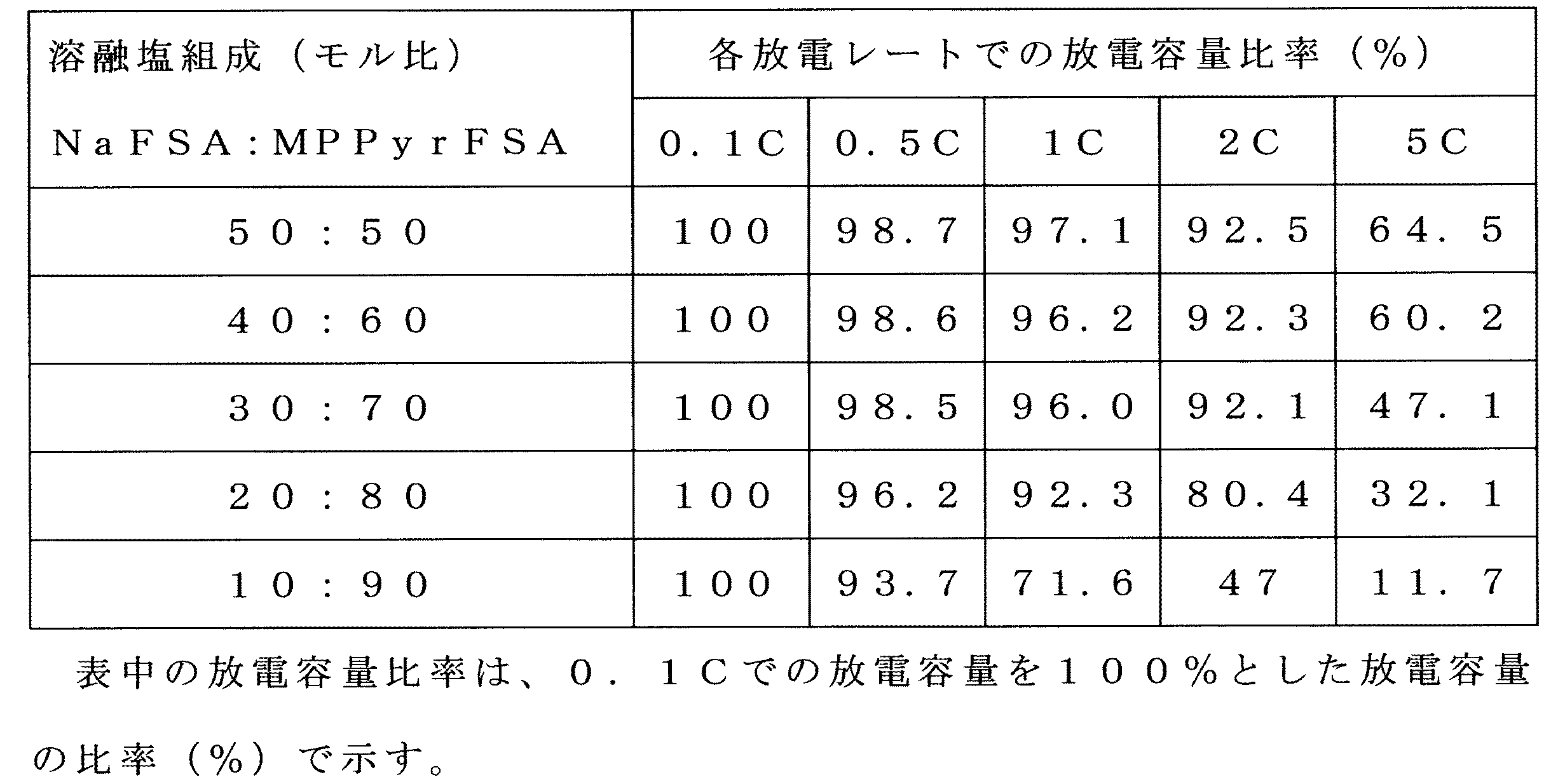
- Each of the five types of secondary batteries produced was subjected to a charge / discharge test in a voltage range of 1.5 to 3.5 V at a temperature of 90 ° C. (363 K) and a current value of 0.1 C rate.
- the initial discharge capacities (mAh / g (NaCrO 2 )) at 0.1 C were almost the same for all the batteries.
- Experiment 5 In the same manner as in Experiment 4, five types of two types were used as the negative electrode, except that instead of metallic sodium, a hard carbon as an active material and a polyimide binder mixed at a mass ratio of 92: 8 were applied to an aluminum foil. A secondary battery was produced. Each of the fabricated secondary batteries was subjected to a charge / discharge test in a voltage range of 1.5 to 3.5 V at a temperature of 90 ° C. (363 K) and a current value of 0.2 C rate. In the evaluation, the capacity ratio between the positive electrode capacity and the negative electrode capacity was set to be almost constant for all the batteries. As a result of the 0.2 C rate charge / discharge test, it was confirmed that the initial discharge capacity at 0.2 C was almost constant for all the batteries.
- the viscosity rapidly increases as the NaFSA ratio (sodium concentration) in the molten salt composition increases and the temperature decreases.
- the viscosity exceeds 500 cP, workability such as a molten salt material pouring operation during battery assembly is gradually lowered. Further, when the viscosity increases, it becomes difficult to uniformly distribute the electrolyte in the battery.
- NaFSA / (NaFSA + MPPyrFSA) is required in order to satisfy both the points that the discharge characteristics are improved, the workability during battery assembly, and the uniform distribution of electrolyte in the battery.
- (Molar ratio) is preferably 0.2 to 0.5. More preferably, it is 0.35 to 0.45.
Abstract
Description

ナトリウムビスフルオロスルフォニルアミド(NaFSA、三菱マテリアル社製)とメチルプロピルピロリジニウムビスフルオロスルフォニルアミド(MPPyrFSA、バイオトレック社製)を、1:9、2:8、3:7、4:6又は5:5のそれぞれのモル比で混合し、5種類の溶融塩組成物を作製した。この溶融塩組成物について、島津DSC-60(島津製作所社製)を用い、10℃/分のScan RateでDSC測定を行った。得られたDSC曲線を図1に示す。なお、得られた溶融塩組成物のガラス転移点の測定も行った。その結果を下表に示す。

外装部分の材質がステンレスであり内面にはポリテトラフルオロエチレン(PTFE)の絶縁被膜が施されているコインセル(2032型コインセル)中に、正極及び負極を配置し、正極と負極との間にポリオレフィン多孔性隔膜(NPS50μm)を配置した。さらに、正極、負極及び隔膜を、MPPyrFSA:NaFSAが8:2である溶融塩組成物(本発明例)で満たして二次電池を作製した。正極及び負極の構成を以下に示す。
正極:NaCrO2、デンカブラック(電気化学工業社製カーボンブラック)及びポリビニリデンフロライドを質量比85:10:5で混合してなる正極材をアルミニウム箔に塗布したアルミニウム箔塗布品
負極材:ハードカーボン及びポリイミドバインダーを質量比92:8で混合したもの
正極として実験2で用いたものと同じアルミニウム箔塗布品、負極材として金属ナトリウム、隔膜にポリオレフィン多孔性隔膜(NPS50μm)を用い、電圧範囲2.5~3.5V、電流値0.05C相当、温度-10℃とした以外は、実験2と同様にして充放電を繰り返す充放電試験を行った。得られた充放電曲線(充放電時間に対するCell Voltageの変化)を図4に示す。図4に示されるように、この二次電池は、-10℃(263K)でも高いエネルギー密度で動作する。
実験1と同様にして、NaFSA(三菱マテリアル社製)とMPPyrFSA(バイオトレック社製)を、1:9、2:8、3:7、4:6及び5:5のモル比で混合し5種類の溶融塩組成物を作製した。
負極として、金属ナトリウムの代わりに、活物質であるハードカーボン及びポリイミドバインダーを質量比92:8で混合したものをアルミニウム箔に塗布したものを用いた以外は実験4と同様にして5種類の二次電池を作製した。作製された二次電池のそれぞれについて、温度90℃(363K)、0.2Cレートの電流値で電圧範囲1.5~3.5Vでの充放電試験を行なった。なお評価は、正極容量と負極容量の容量比率をいずれの電池もほぼ一定として行なった。0.2Cレート充放電試験の結果、いずれの電池も0.2Cでの初期放電容量は、ほぼ一定であることを確認した。

次に実験4および実験5で使用した5種類の溶融塩組成物について、各温度で粘性を測定した。この測定には、Brookfield Engineering Laboratories社製の型式がDV-II+Proの回転粘度計を用いた。この測定結果を、図5に示す。
Claims (14)
- 二次電池の電解液として使用できる2種以上の溶融塩を混合してなり、かつ明確な融点を有しないことを特徴とする溶融塩組成物。
- 前記2種以上の溶融塩中の少なくとも1種の溶融塩が、25℃以下の融点を有する溶融塩2であることを特徴とする請求項1に記載の溶融塩組成物。
- 前記2種以上の溶融塩中の少なくとも1種の溶融塩が、(RSO2)2N-(2つのRはそれぞれ独立にフッ素原子またはフルオロアルキル基を示す)で表わされるアニオンとアルカリ金属カチオンからなる溶融塩1であることを特徴とする請求項2に記載の溶融塩組成物。
- 溶融塩2を構成するアニオンが、(RSO2)2N-(2つのRはそれぞれ独立にフッ素原子またはフルオロアルキル基を示す)で表わされるアニオンであり、溶融塩2を構成するカチオンのイオン径が、前記溶融塩1を構成するアルカリ金属カチオンのイオン径より3倍以上大きく、かつ溶融塩1と溶融塩2との組成比が、前記溶融塩組成物が明確な融点を示さない組成比の範囲内であることを特徴とする請求項3に記載の溶融塩組成物。
- 前記溶融塩2が、ピリジニウム塩、ピペリジニウム塩、ピロリジニウム塩、イミダゾリウム塩、ピラゾリウム塩およびアンモニウム塩よりなる群より選ばれた少なくとも1種であることを特徴とする請求項3又は請求項4に記載の溶融塩組成物。
- 前記溶融塩2が、1-メチル-1-プロピルピロリジニウム塩であることを特徴とする請求項5に記載の溶融塩組成物。
- (RSO2)2N-で表わされるアニオンが、ビスフルオロスルフォニルアミド、ビストリフルオロアルキルスルフォニルアミド及びフルオロスルホニルトリフルオロアルキルスルフォニルアミドよりなる群より選ばれた少なくとも1種であることを特徴とする請求項3ないし請求項6のいずれか1項に記載の溶融塩組成物。
- 溶融塩1が、ナトリウムビスフルオロスルフォニルアミド、ナトリウムビストリフルオロメチルスルフォニルアミド及びナトリウムフルオロスルホニルトリフルオロメチルスルフォニルアミドよりなる群より選ばれた少なくとも1種の塩であることを特徴とする請求項3ないし請求項7のいずれか1項に記載の溶融塩組成物。
- 溶融塩1が、ナトリウムビスフルオロスルフォニルアミドであり、溶融塩2が、メチルプロピルピロリジニウムビスフルオロスルフォニルアミドであり、ナトリウムビスフルオロスルフォニルアミド/(ナトリウムビスフルオロスルフォニルアミド+メチルプロピルピロリジニウムビスフルオロスルフォニルアミド)(モル比) が0.1を超えることを特徴とする請求項3ないし請求項8 のいずれか1項に記載の溶融塩組成物。
- 溶融塩1が、ナトリウムビスフルオロスルフォニルアミドであり、溶融塩2が、メチルプロピルピロリジニウムビスフルオロスルフォニルアミドであり、ナトリウムビスフルオロスルフォニルアミド/(ナトリウムビスフルオロスルフォニルアミド+メチルプロピルピロリジニウムビスフルオロスルフォニルアミド)(モル比) が0.55以下であることを特徴とする請求項3ないし請求項9のいずれか1項に記載の溶融塩組成物。
- 溶融塩1が、ナトリウムビスフルオロスルフォニルアミドであり、溶融塩2が、メチルプロピルピロリジニウムビスフルオロスルフォニルアミドであり、ナトリウムビスフルオロスルフォニルアミド/(ナトリウムビスフルオロスルフォニルアミド+メチルプロピルピロリジニウムビスフルオロスルフォニルアミド)(モル比)が0.2~0.5であることを特徴とする請求項3ないし請求項10のいずれか1項に記載の溶融塩組成物。
- 請求項1ないし請求項11のいずれか1項に記載の溶融塩組成物を電解液として使用することを特徴とする二次電池。
- 活物質がナトリウム化合物である正極と、活物質が黒鉛化合物、チタン酸ナトリウム、錫、亜鉛及びシリコン合金からなる群より選ばれた少なくとも1種である負極と、前記正極と負極との間に配置された多孔性隔膜とを有することを特徴とする請求項12に記載の二次電池。
- 請求項12又は請求項13に記載の二次電池及び他の二次電池を組み合わせてなることを特徴とする組電池システム。
Priority Applications (4)
| Application Number | Priority Date | Filing Date | Title |
|---|---|---|---|
| US14/422,189 US20150229001A1 (en) | 2012-08-21 | 2013-08-12 | Molten salt composition and secondary battery using the molten salt composition |
| KR1020157007119A KR20150047541A (ko) | 2012-08-21 | 2013-08-12 | 용융염 조성물 및 그 용융염 조성물을 이용한 2차 전지 |
| CN201380044410.XA CN104737355A (zh) | 2012-08-21 | 2013-08-12 | 熔融盐组合物和使用所述熔融盐组合物的二次电池 |
| JP2014531586A JPWO2014030561A1 (ja) | 2012-08-21 | 2013-08-12 | 溶融塩組成物及びその溶融塩組成物を用いた二次電池 |
Applications Claiming Priority (2)
| Application Number | Priority Date | Filing Date | Title |
|---|---|---|---|
| JP2012-182482 | 2012-08-21 | ||
| JP2012182482 | 2012-08-21 |
Publications (1)
| Publication Number | Publication Date |
|---|---|
| WO2014030561A1 true WO2014030561A1 (ja) | 2014-02-27 |
Family
ID=50149870
Family Applications (1)
| Application Number | Title | Priority Date | Filing Date |
|---|---|---|---|
| PCT/JP2013/071770 WO2014030561A1 (ja) | 2012-08-21 | 2013-08-12 | 溶融塩組成物及びその溶融塩組成物を用いた二次電池 |
Country Status (5)
| Country | Link |
|---|---|
| US (1) | US20150229001A1 (ja) |
| JP (1) | JPWO2014030561A1 (ja) |
| KR (1) | KR20150047541A (ja) |
| CN (1) | CN104737355A (ja) |
| WO (1) | WO2014030561A1 (ja) |
Cited By (3)
| Publication number | Priority date | Publication date | Assignee | Title |
|---|---|---|---|---|
| JP2015153531A (ja) * | 2014-02-12 | 2015-08-24 | 住友電気工業株式会社 | ナトリウムイオン二次電池、充放電方法および充放電システム |
| US20160111752A1 (en) * | 2013-05-10 | 2016-04-21 | Sumitomo Electric Industries, Ltd. | Sodium molten-salt battery and molten-salt electrolyte or ionic liquid used therein |
| JP2019008958A (ja) * | 2017-06-23 | 2019-01-17 | 住友電気工業株式会社 | 溶融塩電解質およびカリウム溶融塩電池 |
Families Citing this family (2)
| Publication number | Priority date | Publication date | Assignee | Title |
|---|---|---|---|---|
| EP3459137A2 (en) * | 2016-05-17 | 2019-03-27 | Eos Energy Storage, LLC | Zinc-halide battery using a deep eutectic solvent-based electrolyte |
| US11626638B2 (en) * | 2019-03-05 | 2023-04-11 | Eaglepicher Technologies, Llc | Batteries and methods of using and making the same |
Citations (1)
| Publication number | Priority date | Publication date | Assignee | Title |
|---|---|---|---|---|
| WO2012073653A1 (ja) * | 2010-11-30 | 2012-06-07 | 住友電気工業株式会社 | 溶融塩電池 |
Family Cites Families (4)
| Publication number | Priority date | Publication date | Assignee | Title |
|---|---|---|---|---|
| DE602005025457D1 (de) * | 2004-03-22 | 2011-02-03 | Ube Industries | Nicht-wässrige elektrolytlösung und lithium-sekundärbatterie dieselbe verwendend |
| JP4625744B2 (ja) * | 2005-09-29 | 2011-02-02 | 株式会社東芝 | 非水電解質電池および電池パック |
| JP5273765B2 (ja) * | 2007-09-14 | 2013-08-28 | 国立大学法人京都大学 | 溶融塩組成物及びその利用 |
| WO2011036907A1 (ja) * | 2009-09-28 | 2011-03-31 | 住友電気工業株式会社 | 電池およびエネルギーシステム |
-
2013
- 2013-08-12 US US14/422,189 patent/US20150229001A1/en not_active Abandoned
- 2013-08-12 JP JP2014531586A patent/JPWO2014030561A1/ja not_active Withdrawn
- 2013-08-12 CN CN201380044410.XA patent/CN104737355A/zh active Pending
- 2013-08-12 WO PCT/JP2013/071770 patent/WO2014030561A1/ja active Application Filing
- 2013-08-12 KR KR1020157007119A patent/KR20150047541A/ko not_active Application Discontinuation
Patent Citations (1)
| Publication number | Priority date | Publication date | Assignee | Title |
|---|---|---|---|---|
| WO2012073653A1 (ja) * | 2010-11-30 | 2012-06-07 | 住友電気工業株式会社 | 溶融塩電池 |
Non-Patent Citations (2)
| Title |
|---|
| CHANGSHENG DING ET AL.: "NaFSA-C1C3pyrFSA ionic liquids for sodium secondary battery operating over a wide temperature range", JOURNAL OF POWER SOURCES, vol. 238, 26 March 2013 (2013-03-26), pages 296 - 300, Retrieved from the Internet <URL:http://www.sciencedirect.com/science/article/pii/S0378775313004813> [retrieved on 20130827] * |
| KEISUKE KURODA ET AL.: "NaFSA-MPPyrFSA Nigenkei Ion Ekitai o Mochiita Sodium Niji Denchi", ABSTRACTS, BATTERY SYMPOSIUM IN JAPAN, vol. 52, 19 October 2011 (2011-10-19), pages 234 * |
Cited By (3)
| Publication number | Priority date | Publication date | Assignee | Title |
|---|---|---|---|---|
| US20160111752A1 (en) * | 2013-05-10 | 2016-04-21 | Sumitomo Electric Industries, Ltd. | Sodium molten-salt battery and molten-salt electrolyte or ionic liquid used therein |
| JP2015153531A (ja) * | 2014-02-12 | 2015-08-24 | 住友電気工業株式会社 | ナトリウムイオン二次電池、充放電方法および充放電システム |
| JP2019008958A (ja) * | 2017-06-23 | 2019-01-17 | 住友電気工業株式会社 | 溶融塩電解質およびカリウム溶融塩電池 |
Also Published As
| Publication number | Publication date |
|---|---|
| US20150229001A1 (en) | 2015-08-13 |
| JPWO2014030561A1 (ja) | 2016-07-28 |
| KR20150047541A (ko) | 2015-05-04 |
| CN104737355A (zh) | 2015-06-24 |
Similar Documents
| Publication | Publication Date | Title |
|---|---|---|
| CN107004834B (zh) | 钙基二次电池用电解质和包含该电解质的钙基二次电池 | |
| Jin et al. | An organic ionic plastic crystal electrolyte for rate capability and stability of ambient temperature lithium batteries | |
| EP3187487B1 (en) | Ionic liquid and plastic crystal | |
| WO2014030561A1 (ja) | 溶融塩組成物及びその溶融塩組成物を用いた二次電池 | |
| JP2004103560A (ja) | リチウム−硫黄電池用電解液及びこれを含むリチウム−硫黄電池 | |
| CN107112503B (zh) | 钙基二次电池及包含该钙基二次电池的蓄电池 | |
| JP2004103548A (ja) | リチウム−硫黄電池用正極、およびこれを含むリチウム−硫黄電池 | |
| JP6065443B2 (ja) | 耐熱電池およびその充放電方法 | |
| JP2014107141A (ja) | 溶融塩電池およびその製造方法 | |
| US20180309156A1 (en) | Metal-ion rechargeable cell or battery | |
| Meng et al. | Electrolyte Design for Rechargeable Aluminum-Ion Batteries: Recent Advances and Challenges | |
| RU2608598C2 (ru) | Литий-ионный аккумулятор | |
| JP4701923B2 (ja) | イオン伝導材料およびその利用 | |
| JP5017707B2 (ja) | イオン伝導性組成物およびその製造方法 | |
| JP2012190553A (ja) | 無機固体電解質及びリチウム二次電池 | |
| JP2016189239A (ja) | リチウムイオン二次電池 | |
| JP2019153503A (ja) | 液体金属二次電池 | |
| JP2012243924A (ja) | キャパシタ | |
| JP6931788B2 (ja) | カルシウム蓄電池用のチタン系正極材料およびこれを含むセル | |
| JP2015041433A (ja) | ナトリウム溶融塩電池 | |
| JP2019153582A (ja) | アルカリ金属イオン電池 | |
| JP2014192128A (ja) | 溶融塩、電池用電解質および多価イオン電池 | |
| JP5652132B2 (ja) | 無機固体電解質及びリチウム二次電池 | |
| JP5748178B2 (ja) | 溶融塩電池 | |
| JP5402216B2 (ja) | 非水電解質二次電池 |
Legal Events
| Date | Code | Title | Description |
|---|---|---|---|
| 121 | Ep: the epo has been informed by wipo that ep was designated in this application |
Ref document number: 13830682 Country of ref document: EP Kind code of ref document: A1 |
|
| ENP | Entry into the national phase |
Ref document number: 2014531586 Country of ref document: JP Kind code of ref document: A |
|
| WWE | Wipo information: entry into national phase |
Ref document number: 14422189 Country of ref document: US |
|
| NENP | Non-entry into the national phase |
Ref country code: DE |
|
| ENP | Entry into the national phase |
Ref document number: 20157007119 Country of ref document: KR Kind code of ref document: A |
|
| 122 | Ep: pct application non-entry in european phase |
Ref document number: 13830682 Country of ref document: EP Kind code of ref document: A1 |