WO2014020994A1 - 気象情報表示システム、ヒューマンナビゲーション装置、及び気象情報表示方法 - Google Patents
気象情報表示システム、ヒューマンナビゲーション装置、及び気象情報表示方法 Download PDFInfo
- Publication number
- WO2014020994A1 WO2014020994A1 PCT/JP2013/066050 JP2013066050W WO2014020994A1 WO 2014020994 A1 WO2014020994 A1 WO 2014020994A1 JP 2013066050 W JP2013066050 W JP 2013066050W WO 2014020994 A1 WO2014020994 A1 WO 2014020994A1
- Authority
- WO
- WIPO (PCT)
- Prior art keywords
- weather
- information display
- display system
- reference position
- terminal
- Prior art date
- Legal status (The legal status is an assumption and is not a legal conclusion. Google has not performed a legal analysis and makes no representation as to the accuracy of the status listed.)
- Ceased
Links
Images


Classifications
-
- G—PHYSICS
- G01—MEASURING; TESTING
- G01S—RADIO DIRECTION-FINDING; RADIO NAVIGATION; DETERMINING DISTANCE OR VELOCITY BY USE OF RADIO WAVES; LOCATING OR PRESENCE-DETECTING BY USE OF THE REFLECTION OR RERADIATION OF RADIO WAVES; ANALOGOUS ARRANGEMENTS USING OTHER WAVES
- G01S19/00—Satellite radio beacon positioning systems; Determining position, velocity or attitude using signals transmitted by such systems
- G01S19/38—Determining a navigation solution using signals transmitted by a satellite radio beacon positioning system
- G01S19/39—Determining a navigation solution using signals transmitted by a satellite radio beacon positioning system the satellite radio beacon positioning system transmitting time-stamped messages, e.g. GPS [Global Positioning System], GLONASS [Global Orbiting Navigation Satellite System] or GALILEO
-
- G—PHYSICS
- G06—COMPUTING OR CALCULATING; COUNTING
- G06T—IMAGE DATA PROCESSING OR GENERATION, IN GENERAL
- G06T11/00—Two-dimensional [2D] image generation
- G06T11/60—Creating or editing images; Combining images with text
-
- G—PHYSICS
- G01—MEASURING; TESTING
- G01C—MEASURING DISTANCES, LEVELS OR BEARINGS; SURVEYING; NAVIGATION; GYROSCOPIC INSTRUMENTS; PHOTOGRAMMETRY OR VIDEOGRAMMETRY
- G01C21/00—Navigation; Navigational instruments not provided for in groups G01C1/00 - G01C19/00
- G01C21/26—Navigation; Navigational instruments not provided for in groups G01C1/00 - G01C19/00 specially adapted for navigation in a road network
- G01C21/34—Route searching; Route guidance
- G01C21/36—Input/output arrangements for on-board computers
- G01C21/3691—Retrieval, searching and output of information related to real-time traffic, weather, or environmental conditions
- G01C21/3694—Output thereof on a road map
-
- G—PHYSICS
- G01—MEASURING; TESTING
- G01S—RADIO DIRECTION-FINDING; RADIO NAVIGATION; DETERMINING DISTANCE OR VELOCITY BY USE OF RADIO WAVES; LOCATING OR PRESENCE-DETECTING BY USE OF THE REFLECTION OR RERADIATION OF RADIO WAVES; ANALOGOUS ARRANGEMENTS USING OTHER WAVES
- G01S13/00—Systems using the reflection or reradiation of radio waves, e.g. radar systems; Analogous systems using reflection or reradiation of waves whose nature or wavelength is irrelevant or unspecified
- G01S13/88—Radar or analogous systems specially adapted for specific applications
- G01S13/95—Radar or analogous systems specially adapted for specific applications for meteorological use
-
- G—PHYSICS
- G01—MEASURING; TESTING
- G01S—RADIO DIRECTION-FINDING; RADIO NAVIGATION; DETERMINING DISTANCE OR VELOCITY BY USE OF RADIO WAVES; LOCATING OR PRESENCE-DETECTING BY USE OF THE REFLECTION OR RERADIATION OF RADIO WAVES; ANALOGOUS ARRANGEMENTS USING OTHER WAVES
- G01S19/00—Satellite radio beacon positioning systems; Determining position, velocity or attitude using signals transmitted by such systems
- G01S19/01—Satellite radio beacon positioning systems transmitting time-stamped messages, e.g. GPS [Global Positioning System], GLONASS [Global Orbiting Navigation Satellite System] or GALILEO
- G01S19/13—Receivers
- G01S19/14—Receivers specially adapted for specific applications
-
- G—PHYSICS
- G01—MEASURING; TESTING
- G01S—RADIO DIRECTION-FINDING; RADIO NAVIGATION; DETERMINING DISTANCE OR VELOCITY BY USE OF RADIO WAVES; LOCATING OR PRESENCE-DETECTING BY USE OF THE REFLECTION OR RERADIATION OF RADIO WAVES; ANALOGOUS ARRANGEMENTS USING OTHER WAVES
- G01S7/00—Details of systems according to groups G01S13/00, G01S15/00, G01S17/00
- G01S7/003—Transmission of data between radar, sonar or lidar systems and remote stations
-
- G—PHYSICS
- G01—MEASURING; TESTING
- G01S—RADIO DIRECTION-FINDING; RADIO NAVIGATION; DETERMINING DISTANCE OR VELOCITY BY USE OF RADIO WAVES; LOCATING OR PRESENCE-DETECTING BY USE OF THE REFLECTION OR RERADIATION OF RADIO WAVES; ANALOGOUS ARRANGEMENTS USING OTHER WAVES
- G01S7/00—Details of systems according to groups G01S13/00, G01S15/00, G01S17/00
- G01S7/02—Details of systems according to groups G01S13/00, G01S15/00, G01S17/00 of systems according to group G01S13/00
- G01S7/04—Display arrangements
-
- G—PHYSICS
- G01—MEASURING; TESTING
- G01W—METEOROLOGY
- G01W1/00—Meteorology
- G01W1/02—Instruments for indicating weather conditions by measuring two or more variables, e.g. humidity, pressure, temperature, cloud cover or wind speed
-
- G—PHYSICS
- G06—COMPUTING OR CALCULATING; COUNTING
- G06T—IMAGE DATA PROCESSING OR GENERATION, IN GENERAL
- G06T11/00—Two-dimensional [2D] image generation
- G06T11/60—Creating or editing images; Combining images with text
- G06T11/65—Creating or editing images; Combining images with text on geographic maps
-
- G—PHYSICS
- G09—EDUCATION; CRYPTOGRAPHY; DISPLAY; ADVERTISING; SEALS
- G09B—EDUCATIONAL OR DEMONSTRATION APPLIANCES; APPLIANCES FOR TEACHING, OR COMMUNICATING WITH, THE BLIND, DEAF OR MUTE; MODELS; PLANETARIA; GLOBES; MAPS; DIAGRAMS
- G09B29/00—Maps; Plans; Charts; Diagrams, e.g. route diagram
- G09B29/003—Maps
- G09B29/006—Representation of non-cartographic information on maps, e.g. population distribution, wind direction, radiation levels, air and sea routes
-
- G—PHYSICS
- G09—EDUCATION; CRYPTOGRAPHY; DISPLAY; ADVERTISING; SEALS
- G09B—EDUCATIONAL OR DEMONSTRATION APPLIANCES; APPLIANCES FOR TEACHING, OR COMMUNICATING WITH, THE BLIND, DEAF OR MUTE; MODELS; PLANETARIA; GLOBES; MAPS; DIAGRAMS
- G09B29/00—Maps; Plans; Charts; Diagrams, e.g. route diagram
- G09B29/10—Map spot or coordinate position indicators; Map reading aids
- G09B29/106—Map spot or coordinate position indicators; Map reading aids using electronic means
-
- H—ELECTRICITY
- H04—ELECTRIC COMMUNICATION TECHNIQUE
- H04W—WIRELESS COMMUNICATION NETWORKS
- H04W4/00—Services specially adapted for wireless communication networks; Facilities therefor
- H04W4/02—Services making use of location information
- H04W4/024—Guidance services
-
- H—ELECTRICITY
- H04—ELECTRIC COMMUNICATION TECHNIQUE
- H04W—WIRELESS COMMUNICATION NETWORKS
- H04W4/00—Services specially adapted for wireless communication networks; Facilities therefor
- H04W4/02—Services making use of location information
- H04W4/025—Services making use of location information using location based information parameters
- H04W4/027—Services making use of location information using location based information parameters using movement velocity, acceleration information
-
- Y—GENERAL TAGGING OF NEW TECHNOLOGICAL DEVELOPMENTS; GENERAL TAGGING OF CROSS-SECTIONAL TECHNOLOGIES SPANNING OVER SEVERAL SECTIONS OF THE IPC; TECHNICAL SUBJECTS COVERED BY FORMER USPC CROSS-REFERENCE ART COLLECTIONS [XRACs] AND DIGESTS
- Y02—TECHNOLOGIES OR APPLICATIONS FOR MITIGATION OR ADAPTATION AGAINST CLIMATE CHANGE
- Y02A—TECHNOLOGIES FOR ADAPTATION TO CLIMATE CHANGE
- Y02A90/00—Technologies having an indirect contribution to adaptation to climate change
- Y02A90/10—Information and communication technologies [ICT] supporting adaptation to climate change, e.g. for weather forecasting or climate simulation
Definitions
- the present invention relates to a weather information display system that displays weather information superimposed on a map.
- Patent Documents 1 to 3 a car navigation device having a configuration in which weather information is superimposed on a map is known.
- the map display device of Patent Document 1 acquires weather information indicating the future precipitation probability from the weather information center at regular intervals (every day, etc.). This map display device can superimpose the precipitation probability and the like around the device on the map based on the received weather information. Moreover, this map display apparatus can superimpose and display not only the present but the future position of the own machine, the future precipitation probability, etc. on the map.
- the navigation device of Patent Document 2 acquires meteorological information equivalent to the above by FM broadcasting. In addition to being able to display the future precipitation probability and the like superimposed on the map, this navigation device can create a route that does not encounter rain in consideration of the future precipitation probability and the like.
- the reception processing device of Patent Document 3 can acquire weather information equivalent to the above by data broadcasting and display it by superimposing it on a map. Further, it is described that the reception processing device of Patent Document 3 can be applied to a mobile phone in addition to a car navigation device.
- Patent Documents 1 to 3 are configured to obtain weather information for a long period of time (for example, one day) in advance and display using the weather information. Therefore, with this configuration, it is difficult to accurately grasp the weather after several tens of minutes.
- the weather information acquired in Patent Documents 1 to 3 is prediction information of a type in which the probability of precipitation in units of several hours is displayed, it is a case where information is frequently received from a weather information center or the like.
- the weather information of the above type is provided only in a wide range (for example, city unit), it is impossible to grasp the pinpoint weather such as where the rain falls in the corresponding city. Accordingly, it has not been possible to meet the demand for reliably avoiding rain. In addition, it has been difficult to apply to human navigation devices.
- the present invention has been made in view of the above circumstances, and an object of the present invention is to provide a weather information display system that can grasp pinpoint weather information around the aircraft in real time.
- this weather information display system includes a radar device, an image creation unit, a position acquisition unit, and a display unit.
- the radar device acquires meteorological observation data.
- the video creation unit creates a weather radar video based on weather observation data acquired by the radar device.
- the position acquisition unit is provided in the terminal and acquires the position of the terminal.
- the display unit is provided in the terminal and displays the reference position and the current weather radar image around the reference position superimposed on a map with the position acquired by the position acquisition unit as a reference position. To do.
- the weather information display system includes a plurality of the radar devices. Further, the weather information display system includes a management unit that receives the weather observation data or the weather radar video from a plurality of the radar devices, and transmits the weather observation data or the weather radar video according to a request from the terminal. Prepare.
- unified management can be performed as compared with a configuration in which the radar apparatus and the terminal communicate directly.
- the display unit displays a concentric distance ring centered on the reference position.
- this weather information display system includes a prediction unit that predicts a change in weather over time.
- the display unit can display the weather radar image after a lapse of time.
- the terminal can detect a first operation that is an operation of moving the reference position.
- the display unit displays the reference position after movement and the weather radar image after elapse of time.
- the terminal includes a tilt sensor that can acquire the tilt of the terminal.
- the terminal detects an operation in which the terminal is tilted in a predetermined direction as the first operation.
- this operation can be performed with one hand, it can be easily performed even when an umbrella is held in the other hand.
- the terminal can detect a second operation, which is an operation for elapse of time without moving the reference position.
- the display unit displays the reference position where the position is not changed and the weather radar image after a lapse of time.
- the terminal includes a tilt sensor that can acquire the tilt of the terminal.
- the terminal detects, as the second operation, an operation in which the terminal is tilted in a predetermined direction while performing a predetermined operation.
- this operation can be performed with one hand, it can be easily performed even when an umbrella is held in the other hand.
- the terminal preferably creates and stores a route based on the movement history of the reference position.
- this weather information display system includes a GNSS device that receives a signal from a GNSS satellite.
- the prediction unit predicts a change in weather over time based on the detection result of the GNSS device and the detection result of the radar device.
- the display unit changes a display mode of a mark indicating the reference position.
- the weather observation data includes rain information.
- the display unit displays at least one of a position requiring attention due to the influence of rain and a position of a facility capable of raining.
- this human navigation apparatus includes a communication unit, a position acquisition unit, and a display unit.
- the communication unit receives a weather radar image that is an image created based on weather observation data acquired by a radar device.
- the position acquisition unit acquires the position of the own device.
- the display unit superimposes and displays the reference position and the current weather radar image around the reference position on the map with the position acquired by the position acquisition unit as a reference position.
- this meteorological information display method includes an observation data acquisition step, a video creation step, a position acquisition step, and a display step.
- observation data acquisition step meteorological observation data is acquired by a radar device.
- image creation step a weather radar image is created based on the observation data.
- position acquisition step the position of the terminal is acquired.
- display step with the position acquired in the position acquisition step as a reference position, the reference position and the current weather radar image around the reference position are superimposed and displayed on a map.
- the block diagram which shows the whole structure of a weather information display system.
- FIG. 1 is a block diagram showing the overall configuration of the weather information display system 1.
- the weather information display system 1 of the present embodiment is a system that displays weather information superimposed on a map on a terminal 30 such as a smartphone held by the user.
- the weather information display system 1 can provide detailed weather information (pinpoint weather information) in the vicinity of the user in real time as compared with the conventional configuration. Therefore, it is possible to determine whether or not rain is encountered when a pedestrian moves along a certain route, or to search for a route so that the pedestrian does not encounter rain.
- the weather information display system 1 includes an observation device 10, a management server (management unit) 20, and a terminal 30.
- the observation apparatus 10 is installed on the rooftop of a building and observes rain clouds and the like within a range of about several tens of kilometers from the installation position.
- the observation device 10 includes a radar device 11, a GPS device 12, and a communication unit 13.
- the observation apparatus 10 acquires weather observation data.
- the weather observation data is data related to the weather, and includes, for example, rain information, lightning information, tornado information, and the like. In FIG. 1, only two observation devices 10 are depicted, but actually more observation devices 10 constitute the weather information display system 1.
- the radar device 11 includes a transmission / reception unit and a radar antenna.
- the transmission / reception unit can generate radio waves by a control circuit, a magnetron, or the like.
- the radar antenna radiates radio waves generated by the transmission / reception unit to the outside. Radio waves radiated from the radar antenna are reflected by raindrops, rain clouds, etc., and received by the radar antenna.
- the reflected wave received by the radar antenna is subjected to amplification processing, frequency down-conversion processing, and the like by the transmission / reception unit.
- the distance to a rain cloud or the like can be obtained from the time from when the radar antenna transmits a radio wave until it is received. Further, the direction in which rain clouds or the like exist can be obtained from the elevation angle and azimuth angle when the radar antenna transmits radio waves. In addition, when the elevation angle is increased, the position of the rain cloud in the sky and the amount of water contained in the rain cloud can be acquired. On the other hand, when the elevation angle is reduced, the amount and size of raindrops that are actually falling can be acquired. Furthermore, the speed (speed and direction) of the rain clouds and the like can be obtained by utilizing the fact that the frequency of the reflected wave varies depending on the moving speed of the rain clouds and the like (Doppler processing).
- the GPS device (GNSS device) 12 includes a GPS antenna and a GPS receiver.
- the GPS receiver can calculate the position of its own device by receiving and analyzing the positioning signal from the GPS satellite. It is also known that there is a correlation between the time until the positioning signal arrives and the amount of moisture in the air. In the present embodiment, the moisture content in the air is obtained based on this correlation.
- the processing for analyzing the reflected wave of the radar device 11 and the processing for obtaining the amount of water based on the time until the positioning signal arrives may be performed on the observation device 10 side or on the management server 20 side. Also good.
- the communication unit 13 can communicate via the Internet or the like, and transmits the weather observation data acquired by the radar device 11 and the GPS device 12 or data obtained by processing the weather observation data to the management server 20.
- the observation device 10 may transmit the weather observation data and the like to the terminal 30.
- the management server 20 is installed in a company or the like that provides the weather information display system 1.
- the management server 20 performs overall control regarding the plurality of observation apparatuses 10 and the terminals 30.
- the management server 20 includes a video creation unit 21, a prediction unit 22, a storage unit 23, and a communication unit 24.
- the image creation unit 21 creates a weather radar image based on the weather observation data of the observation device 10.
- the weather radar image is a radar image created based on a reflected wave received by the radar device 11 (including at least one of a reflected wave when the elevation angle is large and a reflection wave when the elevation angle is small).
- This radar image may display only rain clouds that are likely to cause guerrilla heavy rain, for example, by performing threshold processing.
- the prediction unit 22 predicts a change in weather over time. Specifically, the prediction unit 22 predicts the moving direction of the rain cloud based on the speed of the rain cloud obtained by Doppler processing. Further, the prediction unit 22 predicts the development status of the rain cloud based on the moisture content of the rain cloud acquired by the radar device 11 and the moisture content acquired by the GPS device 12. As described above, in the present embodiment, since the rain cloud movement or the like is predicted based on the current radar image instead of the weather forecast performed in advance, it is possible to perform prediction with very high accuracy.
- the storage unit 23 stores position information (attention information) that requires attention due to the influence of rain.
- the alert information includes information such as a location near a river, a road that is prone to flooding, and a location that is prone to landslides.
- the management server 20 can estimate the accumulated rainfall at an arbitrary point based on the past weather radar image. Thereby, for example, it can be determined whether or not the river is flooded, and it can be determined whether or not the user needs to be alerted.
- the storage unit 23 also stores information on facilities where rain can be made (rain stay information).
- the shelter information includes store names, locations, business hours, introductions, etc., such as retail stores, restaurants, and entertainment facilities.
- the communication unit 24 can communicate with the observation apparatus 10 and the terminal 30 via the Internet or the like.
- the management server 20 transmits a weather radar image, its prediction information, alert information, and rainy weather information to the terminal 30.
- the terminal 30 is a device possessed by a user who uses the weather information display system 1, and specifically includes a mobile phone, a smartphone, a tablet terminal, and a human navigation device.
- the human navigation device means a terminal having a function of navigating a person or a bicycle, and is a concept including not only a so-called navigation device (dedicated device) but also a smartphone installed with a navigation application.
- the terminal 30 includes a position acquisition unit 31, an operation detection unit 32, a storage unit 33, a control unit 34, a display unit 35, and a communication unit 36. In FIG. 1, only one terminal 30 is depicted, but actually more terminals 30 constitute the weather information display system 1.
- the position acquisition unit 31 is composed of a GPS receiver or the like, and can calculate the position of its own device by receiving and analyzing a positioning signal from a GPS satellite.
- the position acquisition unit 31 is not limited to a configuration using GPS satellites, but has a configuration for acquiring a position from identification information of a base station of a communication facility or a configuration for acquiring a position from a MAC address of a wireless LAN router. May be.
- the operation detection unit 32 detects an operation performed on the terminal 30 by the user.
- the operation detection unit 32 detects, for example, that a key of the terminal 30 is operated, and that a touch operation is performed when the terminal 30 is a touch panel type.
- the terminal 30 includes an acceleration sensor (tilt sensor), and the inclination of the terminal 30 can be acquired. Therefore, the operation detection unit 32 can detect at what speed the terminal 30 is tilted in which direction.
- the storage unit 33 stores data of an application on the terminal 30 side of the weather information display system 1 (hereinafter simply referred to as an application), map information, and the like.
- the storage unit 33 stores a route created by using the weather information display system 1. A method for creating a route using the weather information display system 1 will be described later.
- the control unit 34 is configured by a CPU or the like, and performs processing according to the operation detected by the operation detection unit 32. In addition, the control unit 34 performs processing for executing the application of the weather information display system 1.
- the display unit 35 is a display such as a liquid crystal or an organic EL, and can display an image generated by the management server 20, the control unit 34, or the like.
- the communication unit 36 can transmit the position information of the own device to the management server 20 and can receive weather radar images and the like from the management server 20.
- the control unit 34 acquires the position of the own device from the position acquisition unit 31 after the application is started. And the control part 34 transmits the position of an own machine to the management server 20 via the communication part 36.
- the management server 20 transmits to the terminal 30 the weather radar image corresponding to the received position, its prediction information, alert information (if alert is necessary), and rainy weather information.
- control unit 34 Based on the received data, the control unit 34 displays weather radar images, alerting information, rainy weather information, and the like on the display unit 35 while superimposing them on the map together with the position of the aircraft itself.
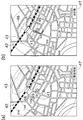
- FIG. 2A shows the screen of the display unit 35 immediately after the application is started. On this screen, a reference position mark 41, a distance ring 42, a weather radar image 43, a caution mark 44, a facility mark 45, a station mark 46, and a time display unit 47 are displayed.
- the reference position mark 41 is a mark indicating the reference position, and indicates the position of the own device immediately after the application is started. In the present embodiment, as shown in FIG. 2B, the reference position can be moved while elapses.
- the distance ring 42 is a concentric part centered on the reference position mark 41.
- the distance ring 42 displays a time required for the user to move linearly to the position of the distance ring 42. Note that the time displayed on the distance ring 42 is set to a value corresponding to the moving means by setting whether the user's moving means is walking or bicycle.
- the weather radar image 43 is obtained by superimposing the weather radar image created by the image creation unit 21 of the management server 20.
- the weather radar image 43 is displayed at the upper right and lower left in FIG. In FIG. 2 and the following figures, only rain clouds that are likely to cause guerrilla heavy rain are displayed.
- Note mark 44 is displayed in the lower left (near the river) in FIG.
- the attention mark 44 is transmitted to the terminal 30 and displayed when the management server 20 determines that it is necessary based on the accumulated rainfall.
- Two facility marks 45 are displayed near the center of FIG. When the user selects the facility mark 45, information such as the store name and business hours of the facility mark 45 is displayed.
- the station mark 46 is a mark indicating a station that is a user's destination in the present description.
- the time display unit 47 indicates how many minutes later the weather radar image 43 is displayed. For example, in FIG. 2A immediately after the activation of the application, since “current time” is displayed on the time display unit 47, it can be seen that the current weather radar image 43 is displayed. Further, in FIG. 4B, since “10 minutes later” is displayed on the time display unit 47, it can be seen that the weather radar image 43 10 minutes after the present is displayed.
- the distance to the station is about 10 minutes in a straight line distance
- the rain cloud is about 20 minutes in a straight line distance.
- the user can confirm that his / her judgment is correct by virtually moving the reference position (reference position mark 41).
- the moving speed of the reference position is set as described above, and the weather radar image 43 moves by the time corresponding to the moving amount of the reference position.
- the weather radar image 43 is moved based on the prediction of the change in weather by the prediction unit 22.
- FIG. 2B shows the state when the reference position is moved and the reference position reaches the position of the station.
- the rain cloud is approaching the reference position, but has not reached the reference position.
- the user can confirm that the determination that “if you depart from now, you can reach the station without encountering guerrilla heavy rain” is correct.
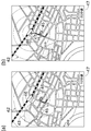
- FIG. 3 (b) shows a state when the reference position and the rain cloud overlap while the reference position is approaching the station.
- the expression of the reference position mark 41 is made different in order to clarify that the rain cloud has overlapped.
- the user encounters guerrilla heavy rain when he departs at the current time and heads for the station.
- the user returns the reference position slightly from the state shown in FIG. 3B (and the time also returns accordingly), and moves the reference position into the facility mark 45. Then, only the time is advanced without changing the reference position (see FIG. 4A and the like). Then, after the rain cloud passes, the reference position mark 41 is again directed to the station. This completes the creation of a route to the station while avoiding encounters with heavy rain.
- a route can be determined by trial and error while referring to changes in weather over time.
- the control unit 34 of the terminal 30 creates a route based on the history (movement history) of virtually moving the reference position as described above. For example, in the example illustrated in FIG. 2, the control unit 34 creates a thick line illustrated in FIG. 2B as a route, which is a history of the user moving the reference position. In the example shown in FIGS. 3 and 4, the control unit 34 creates a thick line shown in FIG. 4B as a route, which is a route finally created by the user after trial and error.
- the control unit 34 stores the path created as described above in the storage unit 33. Thereby, the user can move easily along the created route.
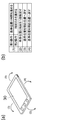
- FIG. 5 is a diagram for explaining an operation method using a tilt sensor.
- FIG. 5A shows the terminal 30 and the direction in which the terminal 30 is tilted.
- an operation of tilting the terminal 30 in the direction (front direction) shown in (1) is referred to as a forward tilt operation
- an operation of tilting the terminal 30 in the direction (backward direction) shown in (2) is referred to as a lateral tilt operation.
- FIG. 5 (b) shows processing executed when each operation is performed.
- the first operation and the second operation are defined in the forward tilt operation of (1).
- the first operation is an operation that simply performs a forward tilt operation without touching the screen
- the second operation is an operation that performs a forward tilt operation while touching the screen.
- the second operation is not limited to this, and may be an operation in which a forward tilt operation is performed after a predetermined key is pressed (or in a pressed state).
- the reference position can be advanced (the time is also advanced simultaneously).
- the second operation (1) it is possible to advance only the time without advancing the reference position. In this way, an operation method that is easy to understand intuitively can be realized by setting the two operations of time advance to be forward tilt operations.
- the advanced reference position can be returned by one step (at the same time the time is returned). In this way, since the reference position can be returned by tilting to the opposite side to the operation of advancing the reference position, an operation method that is easy to understand intuitively can be realized.
- the advanced reference position can be returned to the current position (the time is also returned to the current time) by performing the lateral tilt operations (3) and (4).
- the operation method given here is an example, and can be changed as appropriate.
- the forward tilting operation backward tilting operation
- standard position to the direction which inclined the terminal 30 may be sufficient.
- the weather information display system 1 of the present embodiment includes the radar device 11, the image creation unit 21, the position acquisition unit 31, and the display unit 35.
- the radar apparatus 11 acquires weather observation data.
- the video creation unit 21 creates a weather radar video based on the weather observation data acquired by the radar device 11.
- the position acquisition unit 31 is provided in the terminal 30 and acquires the position of the terminal 30.
- the display unit 35 is provided in the terminal 30 and uses the position acquired by the position acquisition unit 31 as a reference position, and displays the reference position and the current weather radar image around the reference position superimposed on a map. .
- the weather information display system 1 shown above is an example, and the management server 20 or the terminal 30 performs a part of the processing performed by the observation device 10 or the observation device 10 or the terminal performs a part of the processing performed by the management server 20. 30 or a part of the processing performed by the terminal 30 may be performed by the observation apparatus 10 or the management server 20.
- the position information and the moisture content in the air are detected based on the signal from the GPS satellite.
- any configuration can be used as long as the configuration uses GNSS (Global Navigation Satellite System).
- GNSS Global Navigation Satellite System
- the same processing can be performed based on a signal from a GLONASS satellite or a GALILEO satellite.
- the present invention is applied to a system for navigating a pedestrian or a bicycle.
- the present invention can also be applied to a navigation system such as a car or a ship.
Landscapes
- Engineering & Computer Science (AREA)
- Radar, Positioning & Navigation (AREA)
- Remote Sensing (AREA)
- Physics & Mathematics (AREA)
- General Physics & Mathematics (AREA)
- Computer Networks & Wireless Communication (AREA)
- Theoretical Computer Science (AREA)
- Ecology (AREA)
- Environmental & Geological Engineering (AREA)
- Life Sciences & Earth Sciences (AREA)
- Signal Processing (AREA)
- Atmospheric Sciences (AREA)
- Biodiversity & Conservation Biology (AREA)
- Environmental Sciences (AREA)
- Mathematical Physics (AREA)
- Business, Economics & Management (AREA)
- Educational Administration (AREA)
- Educational Technology (AREA)
- Electromagnetism (AREA)
- Automation & Control Theory (AREA)
- Navigation (AREA)
- Instructional Devices (AREA)
- Traffic Control Systems (AREA)
Abstract
Description
11 レーダ装置
12 GPS装置(GNSS装置)
13 通信部
20 管理サーバ(管理部)
30 端末
41 基準位置マーク
42 距離環
43 気象レーダ映像
Claims (14)
- 気象観測データを取得するレーダ装置と、
前記レーダ装置が取得した気象観測データに基づいて気象レーダ映像を作成する映像作成部と、
端末に設けられ、当該端末の位置を取得する位置取得部と、
前記端末に設けられ、前記位置取得部が取得した位置を基準位置として、当該基準位置と、当該基準位置の周囲の現在の前記気象レーダ映像と、を地図に重畳して表示する表示部と、
を備えることを特徴とする気象情報表示システム。 - 請求項1に記載の気象情報表示システムであって、
前記レーダ装置を複数備え、
複数の前記レーダ装置から前記気象観測データ又は前記気象レーダ映像を受信し、前記端末の要求に応じて、当該気象観測データ又は当該気象レーダ映像を送信する管理部を備えることを特徴とする気象情報表示システム。 - 請求項1又は2に記載の気象情報表示システムであって、
前記表示部は、前記基準位置を中心とした同心円状の距離環を表示することを特徴とする気象情報表示システム。 - 請求項1から3までの何れか一項に記載の気象情報表示システムであって、
時間を経過させたときの気象の変化を予測する予測部を備え、
前記表示部は、時間を経過させた後の前記気象レーダ映像を表示可能であることを特徴とする気象情報表示システム。 - 請求項4に記載の気象情報表示システムであって、
前記端末は、前記基準位置を移動させる操作である第1操作を検出可能であり、
前記表示部は、前記第1操作が検出されると、移動後の前記基準位置と、時間を経過させた後の前記気象レーダ映像と、を表示することを特徴とする気象情報表示システム。 - 請求項5に記載の気象情報表示システムであって、
前記端末は、自機の傾きを取得可能な傾斜センサを備え、
前記端末は、自機が所定の向きに傾けられる操作を前記第1操作として検出することを特徴とする気象情報表示システム。 - 請求項4から6までの何れか一項に記載の気象情報表示システムであって、
前記端末は、前記基準位置を移動させずに時間を経過させる操作である第2操作を検出可能であり、
前記表示部は、前記第2操作が検出されると、位置の変更がない前記基準位置と、時間を経過させた後の前記気象レーダ映像と、を表示することを特徴とする気象情報表示システム。 - 請求項7に記載の気象情報表示システムであって、
前記端末は、自機の傾きを取得可能な傾斜センサを備え、
前記端末は、所定の操作を行いながら自機が所定の向きに傾けられる操作を前記第2操作として検出することを特徴とする気象情報表示システム。 - 請求項5から8までの何れか一項に記載の気象情報表示システムであって、
前記端末は、前記基準位置の移動履歴に基づいて、経路を作成して記憶することを特徴とする気象情報表示システム。 - 請求項4から9までの何れか一項に記載の気象情報表示システムであって、
GNSS衛星からの信号を受信するGNSS装置を備え、
前記予測部は、前記GNSS装置の検出結果と、前記レーダ装置の検出結果と、に基づいて、時間を経過させたときの気象の変化を予測することを特徴とする気象情報表示システム。 - 請求項1から10までの何れか一項に記載の気象情報表示システムであって、
前記表示部は、前記気象レーダ映像と前記基準位置とが重なったときに、当該基準位置を示すマークの表示態様を異ならせることを特徴とする気象情報表示システム。 - 請求項1から11までの何れか一項に記載の気象情報表示システムであって、
前記気象観測データには雨情報が含まれ、
前記表示部は、雨の影響により注意が必要となる位置、及び、雨宿りが可能な施設の位置のうち少なくとも何れかを表示することを特徴とする気象情報表示システム。 - レーダ装置により取得された気象観測データに基づいて作成された映像である気象レーダ映像を受信する通信部と、
自機の位置を取得する位置取得部と、
前記位置取得部が取得した位置を基準位置として、当該基準位置と、当該基準位置の周囲の現在の前記気象レーダ映像と、を地図に重畳して表示する表示部と、
を備えることを特徴とするヒューマンナビゲーション装置。 - 気象観測データをレーダ装置により取得する観測データ取得工程と、
前記気象観測データに基づいて気象レーダ映像を作成する映像作成工程と、
端末の位置を取得する位置取得工程と、
前記位置取得工程で取得した位置を基準位置として、当該基準位置と、当該基準位置の周囲の現在の前記気象レーダ映像と、を地図に重畳して表示する表示工程と、
を含むことを特徴とする気象情報表示方法。
Priority Applications (2)
| Application Number | Priority Date | Filing Date | Title |
|---|---|---|---|
| US14/417,781 US20150206330A1 (en) | 2012-07-31 | 2013-06-11 | Weather information display system, human navigation device, and method of displaying weather information |
| JP2014528036A JPWO2014020994A1 (ja) | 2012-07-31 | 2013-06-11 | 気象情報表示システム、ヒューマンナビゲーション装置、及び気象情報表示方法 |
Applications Claiming Priority (2)
| Application Number | Priority Date | Filing Date | Title |
|---|---|---|---|
| JP2012170071 | 2012-07-31 | ||
| JP2012-170071 | 2012-07-31 |
Publications (1)
| Publication Number | Publication Date |
|---|---|
| WO2014020994A1 true WO2014020994A1 (ja) | 2014-02-06 |
Family
ID=50027685
Family Applications (1)
| Application Number | Title | Priority Date | Filing Date |
|---|---|---|---|
| PCT/JP2013/066050 Ceased WO2014020994A1 (ja) | 2012-07-31 | 2013-06-11 | 気象情報表示システム、ヒューマンナビゲーション装置、及び気象情報表示方法 |
Country Status (3)
| Country | Link |
|---|---|
| US (1) | US20150206330A1 (ja) |
| JP (1) | JPWO2014020994A1 (ja) |
| WO (1) | WO2014020994A1 (ja) |
Cited By (5)
| Publication number | Priority date | Publication date | Assignee | Title |
|---|---|---|---|---|
| CN104597522A (zh) * | 2014-12-19 | 2015-05-06 | 阳珍秀 | 一种气象信息提示方法及其提示系统 |
| WO2018147198A1 (ja) * | 2017-02-09 | 2018-08-16 | シャープ株式会社 | 表示装置、テレビジョン受像機、表示制御プログラム、および記録媒体 |
| CN109212630A (zh) * | 2018-10-12 | 2019-01-15 | 重庆长安汽车股份有限公司 | 实现行车目的地环境气候自动提示的系统及方法 |
| WO2020217923A1 (ja) * | 2019-04-26 | 2020-10-29 | 株式会社Jvcケンウッド | ナビゲーション装置、その処理方法、及びプログラム |
| WO2021199320A1 (ja) * | 2020-03-31 | 2021-10-07 | 本田技研工業株式会社 | 制御装置、鞍乗型車両、制御装置の動作方法およびプログラム |
Families Citing this family (7)
| Publication number | Priority date | Publication date | Assignee | Title |
|---|---|---|---|---|
| US9995848B2 (en) | 2015-09-16 | 2018-06-12 | International Business Machines Corporation | Adaptive placement of weather sensors in response to dynamic local conditions |
| US9581727B1 (en) * | 2016-01-22 | 2017-02-28 | Harris Corporation | Severe weather situational awareness system and related methods |
| US11688281B2 (en) | 2020-11-25 | 2023-06-27 | International Business Machines Corporation | Determining shelter areas for two-wheeler vehicles |
| DE102021119782A1 (de) | 2021-07-29 | 2023-02-02 | Bayerische Motoren Werke Aktiengesellschaft | Verfahren und Vorrichtung zur Ermittlung einer Route durch ein Wegenetz |
| DE102022108428A1 (de) * | 2022-04-07 | 2023-10-12 | Infineon Technologies Ag | Radarvorrichtung mit kompensation von nichtlinearitäten |
| JP2024016560A (ja) * | 2022-07-26 | 2024-02-07 | 株式会社東芝 | レーダシステム、データ転送装置及び方法 |
| CN116973913A (zh) * | 2023-08-02 | 2023-10-31 | 四川数字交通科技股份有限公司 | 边坡雷达的控制方法、装置和边坡雷达系统 |
Citations (11)
| Publication number | Priority date | Publication date | Assignee | Title |
|---|---|---|---|---|
| JP2000193469A (ja) * | 1998-10-21 | 2000-07-14 | Sony Corp | ナビゲ―ション装置及び経路表示装置 |
| JP2001264456A (ja) * | 2000-03-22 | 2001-09-26 | Nippon Telegr & Teleph Corp <Ntt> | 気象情報提供方法及びその装置 |
| JP2003084909A (ja) * | 2001-09-12 | 2003-03-20 | Clarion Co Ltd | 入力操作装置、情報選択システムと方法、およびそのためのプログラム |
| JP2006030013A (ja) * | 2004-07-16 | 2006-02-02 | Foundation Of River & Basin Integrated Communications Japan | 全国合成レーダ雨量情報提供システム |
| JP2006226685A (ja) * | 2005-02-15 | 2006-08-31 | Japan Radio Co Ltd | 移動予測表示装置およびレーダシステム |
| JP2009244068A (ja) * | 2008-03-31 | 2009-10-22 | Xanavi Informatics Corp | ナビゲーション装置 |
| JP2010085359A (ja) * | 2008-10-02 | 2010-04-15 | Aisin Aw Co Ltd | ナビゲーション装置、ナビゲーション装置の回避領域設定方法及びプログラム |
| JP2011022106A (ja) * | 2009-07-21 | 2011-02-03 | Jvc Kenwood Holdings Inc | 情報表示装置、経路設定方法およびプログラム |
| JP2011080815A (ja) * | 2009-10-06 | 2011-04-21 | Mitsubishi Electric Corp | サーバ、車載ナビゲーション装置、および車載ナビゲーションシステム |
| JP2011179931A (ja) * | 2010-02-26 | 2011-09-15 | Aisin Aw Co Ltd | ナビゲーション装置及びナビゲーションプログラム |
| JP2012058632A (ja) * | 2010-09-13 | 2012-03-22 | Quick Delivery Co Ltd | 情報提供媒体および情報提供システム |
Family Cites Families (7)
| Publication number | Priority date | Publication date | Assignee | Title |
|---|---|---|---|---|
| US7664601B2 (en) * | 1999-11-10 | 2010-02-16 | Honeywell International Inc. | Weather incident prediction |
| US6340946B1 (en) * | 2000-08-03 | 2002-01-22 | Massachusetts Institue Of Technology | Method for determining storm predictability |
| JP4695864B2 (ja) * | 2004-10-18 | 2011-06-08 | クラリオン株式会社 | ナビゲーション装置、地図データ配信装置、地図データ配信システム |
| WO2007005328A2 (en) * | 2005-06-30 | 2007-01-11 | Massachusetts Institute Of Technology | Weather radar echo tops forecast generation |
| JP4925857B2 (ja) * | 2007-02-20 | 2012-05-09 | 株式会社ナビタイムジャパン | 地図表示システム、携帯端末装置、地図スクロール方法 |
| JP5225820B2 (ja) * | 2008-11-25 | 2013-07-03 | アイシン精機株式会社 | 入力装置、車両周辺監視装置、アイコンスイッチ選択方法及びプログラム |
| US20100256981A1 (en) * | 2009-04-03 | 2010-10-07 | Certusview Technologies, Llc | Methods, apparatus, and systems for documenting and reporting events via time-elapsed geo-referenced electronic drawings |
-
2013
- 2013-06-11 US US14/417,781 patent/US20150206330A1/en not_active Abandoned
- 2013-06-11 JP JP2014528036A patent/JPWO2014020994A1/ja active Pending
- 2013-06-11 WO PCT/JP2013/066050 patent/WO2014020994A1/ja not_active Ceased
Patent Citations (11)
| Publication number | Priority date | Publication date | Assignee | Title |
|---|---|---|---|---|
| JP2000193469A (ja) * | 1998-10-21 | 2000-07-14 | Sony Corp | ナビゲ―ション装置及び経路表示装置 |
| JP2001264456A (ja) * | 2000-03-22 | 2001-09-26 | Nippon Telegr & Teleph Corp <Ntt> | 気象情報提供方法及びその装置 |
| JP2003084909A (ja) * | 2001-09-12 | 2003-03-20 | Clarion Co Ltd | 入力操作装置、情報選択システムと方法、およびそのためのプログラム |
| JP2006030013A (ja) * | 2004-07-16 | 2006-02-02 | Foundation Of River & Basin Integrated Communications Japan | 全国合成レーダ雨量情報提供システム |
| JP2006226685A (ja) * | 2005-02-15 | 2006-08-31 | Japan Radio Co Ltd | 移動予測表示装置およびレーダシステム |
| JP2009244068A (ja) * | 2008-03-31 | 2009-10-22 | Xanavi Informatics Corp | ナビゲーション装置 |
| JP2010085359A (ja) * | 2008-10-02 | 2010-04-15 | Aisin Aw Co Ltd | ナビゲーション装置、ナビゲーション装置の回避領域設定方法及びプログラム |
| JP2011022106A (ja) * | 2009-07-21 | 2011-02-03 | Jvc Kenwood Holdings Inc | 情報表示装置、経路設定方法およびプログラム |
| JP2011080815A (ja) * | 2009-10-06 | 2011-04-21 | Mitsubishi Electric Corp | サーバ、車載ナビゲーション装置、および車載ナビゲーションシステム |
| JP2011179931A (ja) * | 2010-02-26 | 2011-09-15 | Aisin Aw Co Ltd | ナビゲーション装置及びナビゲーションプログラム |
| JP2012058632A (ja) * | 2010-09-13 | 2012-03-22 | Quick Delivery Co Ltd | 情報提供媒体および情報提供システム |
Cited By (11)
| Publication number | Priority date | Publication date | Assignee | Title |
|---|---|---|---|---|
| CN104597522A (zh) * | 2014-12-19 | 2015-05-06 | 阳珍秀 | 一种气象信息提示方法及其提示系统 |
| WO2018147198A1 (ja) * | 2017-02-09 | 2018-08-16 | シャープ株式会社 | 表示装置、テレビジョン受像機、表示制御プログラム、および記録媒体 |
| JP2018128592A (ja) * | 2017-02-09 | 2018-08-16 | シャープ株式会社 | 表示装置、テレビジョン受像機、表示制御プログラム、および記録媒体 |
| CN109212630A (zh) * | 2018-10-12 | 2019-01-15 | 重庆长安汽车股份有限公司 | 实现行车目的地环境气候自动提示的系统及方法 |
| WO2020217923A1 (ja) * | 2019-04-26 | 2020-10-29 | 株式会社Jvcケンウッド | ナビゲーション装置、その処理方法、及びプログラム |
| JP2020180909A (ja) * | 2019-04-26 | 2020-11-05 | 株式会社Jvcケンウッド | ナビゲーション装置、その処理方法、及びプログラム |
| JP7188267B2 (ja) | 2019-04-26 | 2022-12-13 | 株式会社Jvcケンウッド | ナビゲーション装置、その処理方法、及びプログラム |
| WO2021199320A1 (ja) * | 2020-03-31 | 2021-10-07 | 本田技研工業株式会社 | 制御装置、鞍乗型車両、制御装置の動作方法およびプログラム |
| JPWO2021199320A1 (ja) * | 2020-03-31 | 2021-10-07 | ||
| CN115151959A (zh) * | 2020-03-31 | 2022-10-04 | 本田技研工业株式会社 | 控制装置、跨骑型车辆、控制装置的动作方法以及程序 |
| JP7364788B2 (ja) | 2020-03-31 | 2023-10-18 | 本田技研工業株式会社 | 制御装置、鞍乗型車両、制御装置の動作方法およびプログラム |
Also Published As
| Publication number | Publication date |
|---|---|
| JPWO2014020994A1 (ja) | 2016-07-21 |
| US20150206330A1 (en) | 2015-07-23 |
Similar Documents
| Publication | Publication Date | Title |
|---|---|---|
| WO2014020994A1 (ja) | 気象情報表示システム、ヒューマンナビゲーション装置、及び気象情報表示方法 | |
| WO2014020995A1 (ja) | 気象情報表示システム、ヒューマンナビゲーション装置、気象情報表示プログラム及び気象情報表示方法 | |
| EP2769333B1 (en) | Video based pedestrian traffic estimation | |
| US8970620B2 (en) | Position information providing device, position information providing method, position information providing system, and program | |
| US7859429B2 (en) | Weather information display device | |
| US20230119887A1 (en) | Travel control device and travel control method | |
| KR101436223B1 (ko) | 궤적 기반 위치 결정을 이용한 이미지 식별 | |
| US10251019B2 (en) | Adaptive position indicator | |
| US20190137595A1 (en) | Control device for vehicle | |
| US20110298923A1 (en) | Moving object image capture system, moving object, ground station apparatus, and moving object image capture method | |
| US7971153B2 (en) | Weather information display apparatus and program | |
| AU2018230677B2 (en) | Target detection and mapping | |
| KR20150084927A (ko) | 모바일 디바이스들 대신 특정 환경들에 대해 환경 및 기준 데이터 리포트들을 생성하기 위한 기술들 | |
| WO2008138403A1 (en) | Navigation assistance using camera | |
| CN106707315A (zh) | 使用来自过去和当前历元的测量的位置确定 | |
| US10306559B2 (en) | Power management of a global navigation satellite system (GNSS) receiver in a traffic tunnel | |
| JP2018109535A (ja) | 情報処理システム、および情報処理方法 | |
| Juhari et al. | IIum bus on campus monitoring system | |
| CN201503271U (zh) | 具有即时信息显示的导航装置 | |
| KR20100029453A (ko) | 네비게이션 장치를 이용한 태양 및 날씨 표시 시스템 및 그방법 | |
| KR20150102837A (ko) | 군집 주행에 따른 차량의 주행 경로 보정 시스템 및 방법 | |
| US12498247B2 (en) | Enhancements to map reliability | |
| WO2020079418A1 (en) | Location method, portable device and system | |
| JP2016169991A (ja) | 経路案内装置、経路案内方法及び経路案内プログラム |
Legal Events
| Date | Code | Title | Description |
|---|---|---|---|
| 121 | Ep: the epo has been informed by wipo that ep was designated in this application |
Ref document number: 13824821 Country of ref document: EP Kind code of ref document: A1 |
|
| ENP | Entry into the national phase |
Ref document number: 2014528036 Country of ref document: JP Kind code of ref document: A |
|
| WWE | Wipo information: entry into national phase |
Ref document number: 14417781 Country of ref document: US |
|
| NENP | Non-entry into the national phase |
Ref country code: DE |
|
| 122 | Ep: pct application non-entry in european phase |
Ref document number: 13824821 Country of ref document: EP Kind code of ref document: A1 |