WO2014020635A1 - 輸液ポンプ - Google Patents
輸液ポンプ Download PDFInfo
- Publication number
- WO2014020635A1 WO2014020635A1 PCT/JP2012/004845 JP2012004845W WO2014020635A1 WO 2014020635 A1 WO2014020635 A1 WO 2014020635A1 JP 2012004845 W JP2012004845 W JP 2012004845W WO 2014020635 A1 WO2014020635 A1 WO 2014020635A1
- Authority
- WO
- WIPO (PCT)
- Prior art keywords
- unit
- main body
- infusion tube
- tube
- infusion
- Prior art date
- Legal status (The legal status is an assumption and is not a legal conclusion. Google has not performed a legal analysis and makes no representation as to the accuracy of the status listed.)
- Ceased
Links
Images







Classifications
-
- A—HUMAN NECESSITIES
- A61—MEDICAL OR VETERINARY SCIENCE; HYGIENE
- A61M—DEVICES FOR INTRODUCING MEDIA INTO, OR ONTO, THE BODY; DEVICES FOR TRANSDUCING BODY MEDIA OR FOR TAKING MEDIA FROM THE BODY; DEVICES FOR PRODUCING OR ENDING SLEEP OR STUPOR
- A61M5/00—Devices for bringing media into the body in a subcutaneous, intra-vascular or intramuscular way; Accessories therefor, e.g. filling or cleaning devices, arm-rests
- A61M5/36—Devices for bringing media into the body in a subcutaneous, intra-vascular or intramuscular way; Accessories therefor, e.g. filling or cleaning devices, arm-rests with means for eliminating or preventing injection or infusion of air into body
- A61M5/365—Air detectors
-
- A—HUMAN NECESSITIES
- A61—MEDICAL OR VETERINARY SCIENCE; HYGIENE
- A61M—DEVICES FOR INTRODUCING MEDIA INTO, OR ONTO, THE BODY; DEVICES FOR TRANSDUCING BODY MEDIA OR FOR TAKING MEDIA FROM THE BODY; DEVICES FOR PRODUCING OR ENDING SLEEP OR STUPOR
- A61M5/00—Devices for bringing media into the body in a subcutaneous, intra-vascular or intramuscular way; Accessories therefor, e.g. filling or cleaning devices, arm-rests
- A61M5/14—Infusion devices, e.g. infusing by gravity; Blood infusion; Accessories therefor
- A61M5/142—Pressure infusion, e.g. using pumps
- A61M5/14212—Pumping with an aspiration and an expulsion action
- A61M5/14228—Pumping with an aspiration and an expulsion action with linear peristaltic action, i.e. comprising at least three pressurising members or a helical member
-
- A—HUMAN NECESSITIES
- A61—MEDICAL OR VETERINARY SCIENCE; HYGIENE
- A61M—DEVICES FOR INTRODUCING MEDIA INTO, OR ONTO, THE BODY; DEVICES FOR TRANSDUCING BODY MEDIA OR FOR TAKING MEDIA FROM THE BODY; DEVICES FOR PRODUCING OR ENDING SLEEP OR STUPOR
- A61M5/00—Devices for bringing media into the body in a subcutaneous, intra-vascular or intramuscular way; Accessories therefor, e.g. filling or cleaning devices, arm-rests
- A61M5/14—Infusion devices, e.g. infusing by gravity; Blood infusion; Accessories therefor
- A61M5/168—Means for controlling media flow to the body or for metering media to the body, e.g. drip meters, counters ; Monitoring media flow to the body
- A61M5/16831—Monitoring, detecting, signalling or eliminating infusion flow anomalies
- A61M2005/16863—Occlusion detection
- A61M2005/16868—Downstream occlusion sensors
-
- A—HUMAN NECESSITIES
- A61—MEDICAL OR VETERINARY SCIENCE; HYGIENE
- A61M—DEVICES FOR INTRODUCING MEDIA INTO, OR ONTO, THE BODY; DEVICES FOR TRANSDUCING BODY MEDIA OR FOR TAKING MEDIA FROM THE BODY; DEVICES FOR PRODUCING OR ENDING SLEEP OR STUPOR
- A61M5/00—Devices for bringing media into the body in a subcutaneous, intra-vascular or intramuscular way; Accessories therefor, e.g. filling or cleaning devices, arm-rests
- A61M5/14—Infusion devices, e.g. infusing by gravity; Blood infusion; Accessories therefor
- A61M5/168—Means for controlling media flow to the body or for metering media to the body, e.g. drip meters, counters ; Monitoring media flow to the body
- A61M5/16831—Monitoring, detecting, signalling or eliminating infusion flow anomalies
- A61M2005/16863—Occlusion detection
- A61M2005/16872—Upstream occlusion sensors
-
- A—HUMAN NECESSITIES
- A61—MEDICAL OR VETERINARY SCIENCE; HYGIENE
- A61M—DEVICES FOR INTRODUCING MEDIA INTO, OR ONTO, THE BODY; DEVICES FOR TRANSDUCING BODY MEDIA OR FOR TAKING MEDIA FROM THE BODY; DEVICES FOR PRODUCING OR ENDING SLEEP OR STUPOR
- A61M2205/00—General characteristics of the apparatus
- A61M2205/33—Controlling, regulating or measuring
- A61M2205/3375—Acoustical, e.g. ultrasonic, measuring means
Definitions
- the present invention relates to an infusion pump for delivering a medicine or the like to a patient.
- the present invention relates to an infusion pump in which electrical wiring is extended to an open / close cover that is supported rotatably by a hinge and covers an infusion tube attached to a tube attachment portion of an infusion pump main body.
- the infusion pump is used, for example, in an intensive care unit (ICU) or the like, and is used to perform a liquid feeding treatment for a patient for a long time with high accuracy.
- a predetermined drug bag (infusion bag) is arranged on the infusion pump, and an infusion tube lowered from the drug bag is sandwiched between the main body and the door, and the infusion tube is accommodated in the main body.
- the door is held by closing the door.
- the outer peripheral surface of the infusion tube set at a fixed position is sandwiched between a plurality of fingers in the main body and the inner surface of the door.
- This infusion pump is a peristaltic infusion in which a plurality of fingers of a liquid feeding drive unit are individually driven, and a plurality of fingers sequentially press the outer peripheral surface of the infusion tube along the length direction to feed a medicine.
- a spear that is a pump (see Patent Document 1).
- the infusion tube is held vertically through the infusion pump main body from top to bottom.
- an infusion pump that holds an infusion tube in a horizontal direction in the body of the infusion pump has been proposed.
- the infusion pump has a structure in which the infusion tube is held in the horizontal direction in the main body of the infusion pump so that the infusion tube passes vertically through the main body of the infusion pump from top to bottom. This is because the infusion tube does not get in the way even if a plurality of infusion pumps are stacked and held in a stacked state in the vertical position.
- the upstream side of the infusion tube is disposed on the right side of the infusion pump main body, and the downstream side of the infusion tube is disposed on the left side of the infusion pump main body.
- the upstream side of the infusion tube is arranged on the right side portion of the main body of the infusion pump, and the downstream side of the infusion tube is arranged on the left side portion of the main body of the infusion pump, the liquid feeding drive unit is driven,
- the medicine can be delivered from the upstream side to the downstream side along a predetermined delivery direction, and can be delivered correctly to the patient.
- the infusion pump has a bubble sensor for detecting whether or not bubbles are present in the infusion tube.
- the infusion pump is used in, for example, an intensive care unit (ICU), but the bubble sensor may receive noise from a medical instrument such as an electric knife. If the bubble sensor receives noise, there is a risk of erroneous detection of the presence or absence of bubbles. Then, an object of this invention is to provide the infusion pump which can prevent the noise from a medical device and can prevent the misdetection of the presence or absence of a bubble.
- ICU intensive care unit
- the infusion pump according to the present invention includes a main body, a tube mounting portion that is disposed in the main body and in which an infusion tube for infusing a medicine to the patient side is mounted, and is disposed in the main body, and the infusion tube is mounted on the tube In a state where the infusion tube is attached to the tube, the infusion tube is pressurized to send the medicine in the infusion tube in the lateral direction, and attached to the main body and closed to be attached to the tube attachment portion.
- An opening / closing cover that covers the infusion tube, and a bubble sensor that includes an ultrasonic wave transmission unit and an ultrasonic wave reception unit for detecting bubbles in the infusion tube mounted on the tube mounting unit, and the ultrasonic wave And a noise shielding unit that shields noise from the outside with respect to the transmitting unit and the ultrasonic receiving unit.
- the noise sensor since the noise sensor has a noise shielding part that shields noise from the outside with respect to the bubble sensor, the bubble sensor is not adversely affected by noise from the outside due to the noise shielding part. It is possible to prevent erroneous detection of the presence or absence of bubbles.
- the bubble sensor includes the ultrasonic wave transmitting unit and a pressing member disposed on the opening / closing cover, and an ultrasonic wave receiving unit that receives the ultrasonic wave from the ultrasonic wave transmitting unit through the infusion tube.
- the ultrasonic wave transmitting unit of the bubble sensor shields noise by the first shielding member, and the ultrasonic wave receiving unit of the bubble sensor can shield noise by the second shielding member. None of the ultrasonic receivers are affected by noise.
- the first shielding member and the second shielding member are connected to a ground terminal in the main body.
- the first shielding member and the second shielding member can shield noise external to the bubble sensor.
- the flexible cable connected to the ultrasonic wave transmitting portion of the opening / closing cover and guided into the main body portion is provided with a noise shielding shield member.
- the external noise which a flexible cable enters through the clearance gap between an opening-and-closing cover and a main body can be shielded, and it can prevent that a noise mounts on a flexible cable.
- the display unit and the operation panel unit are disposed on the upper part of the main body, and the tube mounting unit, the liquid feeding drive unit, and the opening / closing cover are disposed on the lower part of the main body. It is characterized by that.
- the medical worker can close the open / close cover by attaching the infusion tube to the tube attachment portion while confirming information on the display portion on the upper portion of the main body. Then, the medical worker can operate the operation buttons on the operation panel unit while confirming the information on the display unit on the upper part of the main body.
- the present invention can provide an infusion pump capable of preventing noise from a medical device and preventing erroneous detection of the presence or absence of bubbles.
- the perspective view which shows preferable embodiment of the infusion pump of this invention The perspective view which looked at the infusion pump shown in FIG. 1 from the W direction.
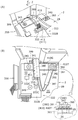
- FIG. 10 is a perspective view illustrating a part of the assembly unit illustrated in FIG. 9 and a part of the outer surface side of the opening / closing cover.
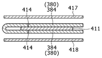
- Sectional drawing which shows the lamination example of a flexible cable and its surrounding component.
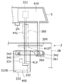
- FIG. 13A is a perspective view showing a state in which the assembly unit shown in FIG. 9 is disposed in the main body
- FIG. 13B shows the assembly unit shown in FIG. Perspective view.
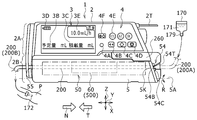
- FIG. 1 is a perspective view showing a preferred embodiment of the infusion pump of the present invention.
- FIG. 2 is a perspective view of the infusion pump shown in FIG. 1 as viewed from the W direction.
- the infusion pump 1 shown in FIGS. 1 and 2 is used, for example, in an intensive care unit (ICU, CCU, NICU) or the like, and is used for nutrition, such as anticancer agents, anesthetics, chemotherapeutic agents, blood transfusions, etc.
- This is a micro continuous infusion pump used for performing a micro infusion treatment of a medicine such as a medicine for a relatively long time with high accuracy.
- This infusion pump 1 is used, for example, for selecting a drug to be used from a drug library and feeding the selected drug.
- This drug library is drug information which is a drug administration setting group including drug names registered in advance in the drug library database (DB). By using this drug library, a medical worker does not have to perform complicated administration settings each time, and can select a drug and set a drug.
- DB drug library database
- the infusion pump 1 can accurately deliver liquid to the patient P from the medicine bag 170 filled with the medicine 171 via the clamp 179, the infusion tube 200, and the indwelling needle 172.
- the drug is also called an infusion.
- An infusion tube is also called an infusion line.
- the infusion pump 1 has a main body cover 2 and a handle 2T, and the handle 2T can be extended in the N direction or stored in the T direction.
- the main body cover 2 is also called a main body, and is integrally formed of a molded resin material having chemical resistance, and can be prevented from entering the infusion pump 1 even if a drug or the like is applied. have.
- the main body cover 2 has the drip-proof treatment structure because the medicine 171 in the medicine bag 170 disposed above spills out or disinfects the disinfecting liquid used in the vicinity. Because there is.
- a display unit 3 and an operation panel unit 4 are arranged on the upper portion 2 ⁇ / b> A of the main body cover 2.
- the display unit 3 is an image display device, and uses, for example, a color liquid crystal display device. This display unit 3 can display not only information notation in Japanese but also information in a plurality of foreign languages as required.
- the display unit 3 is disposed on the upper left side of the upper portion 2 ⁇ / b> A of the main body cover 2 and above the opening / closing cover 5.
- the upper part 2A of the main body cover 2 is the upper half part of the main body cover 2.
- the lower part 2 ⁇ / b> B of the main body cover 2 is a lower half part of the main body cover 2.
- the display unit 3 includes, as an example, a display column 3B for a scheduled amount (mL) of drug administration, a display column 3C for an integrated amount (mL) of drug administration, a display column 3D for a charge history, and a flow rate (mL).
- the display column 3E and the like are displayed, the display contents of the display unit 3 shown in FIG. 1 are omitted for the sake of simplicity of the drawing.
- the display unit 3 can also display a warning message.
- the operation panel unit 4 is disposed on the right side of the display unit 3 in the upper part 2A of the main body cover 2, and the operation panel unit 4 includes, for example, a pilot lamp 4A, a fast-forward switch button 4B, and a start button as illustrated in FIG.
- a switch button 4C, a stop switch button 4D, a menu selection button 4E, a power switch 4F, and the like are arranged.
- an opening / closing cover 5 serving as a lid member is provided on the lower portion 2B of the main body cover 2 so as to be openable and closable in the R direction around a rotating shaft 5A.
- the open / close cover 5 is a plate-like lid member that is formed long along the X direction.
- the tube mounting part 50 and the liquid feeding drive part 60 are disposed inside the opening / closing cover 5.
- An infusion tube 200 made of a flexible thermoplastic resin such as soft vinyl chloride is set in the tube mounting portion 50, and the infusion tube 200 is connected to the tube mounting portion 50 by closing the open / close cover 5. , And can be mounted horizontally along the X direction (T direction). Note that the X direction, the Y direction, and the Z direction in FIGS.
- the X direction is parallel to the T direction, which is the liquid feeding direction, and is the left-right direction of the infusion pump 1.
- the Y direction is the front-rear direction of the infusion pump 1.
- FIG. 3 shows a tube mounting portion 50 and a liquid feeding drive portion 60 for opening the opening / closing cover 5 of the infusion pump 1 shown in FIGS. 1 and 2 and mounting the infusion tube 200.
- the tube mounting part 50 and the liquid feeding drive part 60 are provided in the lower part 1B of the main body of the infusion pump 1 (the lower part 2B of the main body cover 2).
- 60 is provided along the X direction in the lower part of the display unit 3 and the operation panel unit 4.
- the tube mounting part 50 and the liquid feeding drive part 60 can cover the opening / closing cover 5 with the opening / closing cover 5 when the opening / closing cover 5 is closed in the CR direction around the rotating shaft 5A.
- the tube mounting portion 50 includes a bubble sensor 51, an upstream blockage sensor 52, a downstream blockage sensor 53, a tube clamp portion 270, a first infusion tube guide portion 54 at the right side position, and a left side position.
- the second infusion tube guide portion 55 is provided.
- an infusion tube setting direction display unit 150 for clearly displaying the T direction that is the correct liquid feeding direction when the infusion tube 200 is set is provided in the vicinity of the tube mounting unit 50. ing.
- the infusion tube setting direction display unit 150 includes, for example, a plurality of arrows 151.
- the infusion tube setting direction display unit 150 may be printed directly on the lower part of the tube mounting part 50, for example, or may be printed on a seal-like member and attached to the lower part of the tube mounting part 50.
- the infusion tube setting direction display unit 150 is arranged to clearly indicate the liquid feeding direction (T direction) in the correct direction of the medicine 171 by the infusion tube 200 set inside the opening / closing cover 5.
- the medical staff opens the opening / closing cover 5 of FIG. 3 in the CS direction, opens the tube mounting portion 50, and mounts the infusion tube 200 on the tube mounting portion 50, the infusion tube 200 It is possible to clearly indicate the T direction, which is the direction of drug delivery. For this reason, the medical worker can prevent attaching the infusion tube 200 in the reverse direction accidentally while visually confirming.
- the open / close cover 5 is a plate-like member made of a thin molded resin member in order to reduce the weight of the infusion pump 1. Thereby, the weight of the opening / closing cover 5 can be reduced, and the structure can be simplified.
- the opening / closing cover 5 can be opened and closed along the CS direction and the CR direction about the rotation shaft 5A. That is, the opening / closing cover 5 is supported to the main body lower part 2B of the main body cover 2 using the two hinge portions 2H, 2H.
- the two hinge portions 2H and 2H are arranged corresponding to the first hook member 5D and the second hook member 5E, respectively.
- an opening / closing operation lever 260 is provided in the upper right part on the surface side of the opening / closing cover 5.
- an infusion tube pressing member 500 On the inner surface side of the opening / closing cover 5, an infusion tube pressing member 500, a first hook member 5D, and a second hook member 5E are provided.
- the infusion tube pressing member 500 is disposed as a long rectangular and planar protrusion along the X direction, and the infusion tube pressing member 500 is in a position facing the liquid feeding drive unit 60.
- the infusion tube pressing member 500 has a flat surface in the X direction along the liquid feeding drive unit 60, and the infusion tube pressing member 500 closes the opening / closing cover 5 in the CR direction, A part of the infusion tube 200 is pressed between them.
- the medical worker can set the infusion tube 200 on the lower half of the body of the infusion pump 1 along the horizontal direction while confirming the display content displayed on the display unit 3, and the infusion tube 200 is connected to the tube mounting portion. After being set to 50 and the liquid feeding drive unit 60, the infusion tube 200 can be covered by closing the open / close cover 5 in the CR direction as shown in FIGS.
- the first hook member 5D and the second hook member 5E are mechanically simultaneously engaged with the fixing portions 1D and 1E on the lower body 1B side, so that the open / close cover 5 is As shown, the tube mounting portion 50 and the liquid feeding drive portion 60 of the lower main body 1B are held in a closed state.
- the first hook member 5D, the second hook member 5E, and the fixing portions 1D, 1E on the main body lower part 1B side constitute a double hook structure portion 300 of the opening / closing cover 5.
- the tube clamp part 270 shown in FIG. 3 clamps and closes the middle part of the infusion tube 200 by closing the open / close cover 5.
- the tube clamp portion 270 is disposed in the vicinity of the left fixed portion 1E and at a position corresponding to the left second hook member 5E.
- the tube clamp portion 270 can block a part of the infusion tube 200 in the middle.
- the first infusion tube guide portion 54 is provided on the right side of the main body lower portion 1B, and the second infusion tube guide portion 55 is provided on the left side of the main body lower portion 1B.
- the first infusion tube guide portion 54 can be held by fitting the upstream side 200A of the infusion tube 200
- the second infusion tube guide portion 55 can be held by fitting the downstream side 200B of the infusion tube 200
- the infusion tube 200 can be held. It is held in the horizontal direction along the X direction.
- the infusion tube 200 held in the horizontal direction is in the T direction along the bubble sensor 51, the upstream block sensor 52, the liquid feed drive unit 60, the downstream block sensor 53, and the tube clamp unit 270. It is fixed by fitting along.
- the 1st infusion tube guide part 54 has two euros
- the two protrusions 54B and 54C are formed on the lower part 1B of the main body in order to hold the upstream side 200A of the infusion tube 200 detachably when the infusion tube 200 is set in the horizontal direction.
- the inclined guide portion 54T is formed from the two protrusions 54B and 54C toward the diagonally upper right direction, and guides the upstream side 200A of the infusion tube 200 obliquely upward.
- the medical staff can not only visually confirm that the upstream side 200A of the infusion tube 200 is set on the inclined guide portion 54T side, but also the infusion tube.
- the upstream side 200A of 200 can be held without being bent suddenly.
- the medical worker since the inclined guide portion 54T is exposed without being covered with the opening / closing cover 5, the medical worker directly looks at the inclined guide portion 54T, so that the upstream side 200A of the infusion tube 200 is inclined to the inclined guide portion 54T. It can be confirmed that it should be arranged on the side.
- the second infusion tube guide portion 55 is a groove portion formed in the side surface portion 1 ⁇ / b> S of the main body lower portion 1 ⁇ / b> B in order to detachably hold a part of the downstream side 200 ⁇ / b> B of the infusion tube 200. is there.
- the first infusion tube guide portion 54 and the second infusion tube guide portion 55 are provided in the tube attachment portion 50 so that the infusion tube 200 is not sandwiched between the opening / closing cover 5 and the tube attachment portion 50 and crushed. Can be installed securely.
- the right side surface portion 5 ⁇ / b> K of the opening / closing cover 5 is formed to be inclined toward the upper left direction. Thereby, even when the open / close cover 5 is closed, the open / close cover 5 is prevented from covering the two protrusions 54B and 54C of the first infusion tube guide portion 54 and the inclined guide portion 54T.
- the bubble sensor 51 shown in FIG. 3 is a sensor that detects bubbles (air) generated in the infusion tube 200.
- the bubble sensor 51 flows into the infusion tube 200 from the outside of the infusion tube 200 such as soft vinyl chloride.
- It is an ultrasonic sensor that monitors bubbles contained in a medicine.
- the receiving unit monitors the presence or absence of bubbles by detecting the difference in transmittance.
- the bubble sensor 51 has a pressing member 320 and a receiving member 330.
- the ultrasonic wave transmitting portion is disposed on the pressing member 320 on the opening / closing cover 5 side.
- the ultrasonic wave receiving unit is disposed on the receiving member 330 on the main body 2 side.
- the ultrasonic wave receiving unit is disposed on the pressing member 320 on the opening / closing cover 5 side and the ultrasonic wave transmitting unit is disposed on the receiving member 330 on the main body 2 side.
- the structure of placing on the pressing member 320 by shielding the ultrasonic receiving unit for shielding noise becomes complicated.
- the upstream blockage sensor 52 shown in FIG. 3 is a sensor that detects whether or not the inside of the infusion tube 200 is blocked on the upstream side 200A of the infusion tube 200, and the downstream blockage sensor 53 is an infusion solution on the downstream side 200B of the infusion tube 200. It is a sensor that detects whether or not the inside of the tube 200 is closed.
- the upstream blockage sensor 52 and the downstream blockage sensor 53 have the same configuration.
- the case where the infusion tube 200 is blocked is, for example, a case where the viscosity of the medicine to be delivered is high or the concentration of the medicine is high.
- pressing members 452 and 453 are provided on the inner surface side of the opening / closing cover 5 at positions corresponding to the upstream closing sensor 52 and the downstream closing sensor 53, respectively.
- the infusion tube 200 of any size among the plural types of infusion tubes 200 having different diameters is attached to the infusion pump 1, when the open / close cover 5 is closed, the upstream side occlusion sensor 52 and the downstream side occlusion sensor 53 are The occlusion state of the infusion tube 200 can be detected.
- FIG. 4 shows an electrical configuration example of the infusion pump 1.
- the liquid feeding drive unit 60 is moved by a drive motor 61, a cam structure 62 having a plurality of cams rotated by the drive motor 61, and each cam of the cam structure 62.
- a finger structure 63 having a plurality of fingers.
- the cam structure 62 has a plurality of cams, for example, six cams 62A to 62F, and the finger structure 63 has six fingers 63A to 63F corresponding to the six cams 62A to 62F. is doing.
- the six cams 62A to 62F are arranged with a phase difference from each other, and the cam structure 62 is connected to the output shaft 61A of the drive motor 61.
- the six fingers 63A to 63F advance and retract by a predetermined stroke in the Y direction in a predetermined order, whereby the infusion tube 200 is It is pressed against the infusion tube pressing member 500 of the opening / closing cover 5 along the T direction. For this reason, the medicine in infusion tube 200 can be sent in the T direction. That is, when the plurality of fingers 63A to 63F are individually driven, the plurality of fingers 63A to 63F sequentially press the outer peripheral surface of the infusion tube 200 along the T direction to feed the medicine in the infusion tube 200. .
- the fingers 63A to 63F are sequentially moved forward and backward, and as if the wave is traveling, the closing point of the infusion tube 200 is moved in the T direction.
- the drug is transferred by squeezing the tube 200.
- the infusion pump 1 has a control unit (computer) 100 that controls the overall operation.
- the control unit 100 is a one-chip microcomputer, for example, and includes a ROM (read only memory) 101, a RAM (random access memory) 102, a nonvolatile memory 103, and a clock 104.
- the clock 104 can correct the current time by a predetermined operation, and can acquire the current time, measure the elapsed time of a predetermined liquid feeding operation, measure the reference time of liquid feeding speed control, and the like.
- the control unit 100 shown in FIG. 4 is connected to a power switch button 4F and a switch 111.
- the switch 111 supplies power to the control unit 100 from either the power converter unit 112 or the rechargeable battery 113 by switching between the power converter unit 112 and the rechargeable battery 113 such as a lithium ion battery.
- the power converter unit 112 is connected to a commercial AC power source 115 via an outlet 114.
- the display unit driver 130 in FIG. 4 drives the display unit 3 in response to an instruction from the control unit 100, and displays information contents and warning messages illustrated in FIG.
- the speaker 131 can notify various alarm contents by voice according to a command from the control unit 100.
- the buzzer 132 can notify various alarms by sound according to commands from the control unit 100.
- the speaker 131 is an example of a warning unit that issues a warning by voice to a medical worker when the infusion tube 200 is set in the N direction (reverse direction), which is the wrong direction.
- the buzzer 132 is an example of a warning unit that issues a warning by sound to a medical worker when the infusion tube 200 is set in the N direction (reverse direction), which is the wrong direction.
- a downstream block signal S3 indicating that the side is blocked is supplied to the control unit 100.
- the upstream blockage sensor 52 and the downstream blockage sensor 53 can detect a state in which the internal pressure of the infusion circuit exceeds the set pressure in the infusion pump 1 and the medicine cannot be delivered.
- the reason why the internal pressure of the infusion circuit exceeds the set pressure in the infusion pump 1 is that when the infusion needle for infusion or the infusion tube 200 is clogged, the infusion tube 200 is crushed or broken, a highly viscous drug This is the case when using.
- the control unit 100 can communicate bidirectionally with a computer 141 such as a desktop computer through the communication port 140.
- This computer 141 is connected to a drug database (DB) 160, and drug information MF stored in the drug database 160 is acquired by the control unit 100 via the computer 141, and the non-volatile state of the control unit 100 is acquired. It can be stored in the memory 103.
- the control unit 100 can display the drug information MF and the like on the display unit 3 shown in FIG. 2, for example, based on the stored drug information MF.
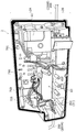
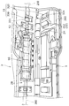
- FIG. 5 shows the inside of the front cover portion 701 of the main body cover 2 shown in FIG. 1, and FIG. 6 shows the inside of the rear cover 702 of the main body cover 2.
- a drive motor 61, a liquid feeding drive unit 60, a main substrate 710, and the like are accommodated and fixed in the front cover portion 701 of the main body cover 2.
- the main board 710 shown in FIG. 5 is mounted with the display unit 3, the display unit driver 130, the operation panel unit 4, the control unit 100, and the like shown in FIG.
- a primary power supply unit (an example of a power supply unit) 720 illustrated in FIG. 6 includes the power converter unit 112, the rechargeable battery 113, and the like illustrated in FIG. As shown in FIG.
- the drive motor 61 and the main board 710 are arranged in the region of the upper portion 2 ⁇ / b> A of the main body cover 2 inside the front cover portion 701 of the main body cover 2.
- the liquid feeding drive unit 60 is disposed in the region of the lower portion 2B inside the front cover portion 701 of the main body cover 2.
- the drive motor 61 and the main substrate 710 are disposed above the liquid supply driving unit 60 and at a position separated from the liquid supply driving unit 60.
- the infusion tube 200 is arranged in the T direction in the infusion drive unit 60, but the drive motor 61 and the main substrate 710 are separated from each other at a position above the infusion tube 200. It is arranged as far as possible from the tube 200. Accordingly, when the infusion pump 1 is operated, the drive motor 61 and the main board 710 generate heat, but the generated heat does not adversely affect the infusion tube 200 and the drug passing through the infusion tube 200. Yes.
- an assembly unit 350 is disposed on the left side inside the front cover portion 701 of the main body cover 2.
- the assembly unit 350 includes a receiving member that incorporates an ultrasonic wave receiving portion of the bubble sensor 51 and a circuit board on which the receiving member is mounted.
- a primary power supply unit 720, an AC inlet board 730, and the like are accommodated and fixed inside the rear cover 702 of the main body cover 2.
- the primary power supply unit 720 and the AC inlet board 730 are arranged in the region of the upper portion 2 ⁇ / b> A inside the rear cover 702 of the main body cover 2. That is, the primary power supply unit 720 and the AC inlet substrate 730 are disposed above the liquid supply driving unit 60 shown in FIG.
- the primary power supply unit 720 and the AC inlet board 730 generate heat.
- the generated heat passes through the infusion tube 200 and the infusion tube 200 passing through the infusion drive unit 60. It does not adversely affect the drug that passes through.
- the drug passing through the infusion tube 200 leaks from the infusion tube 200, the drug does not fall on the primary power supply unit 720 and the AC inlet substrate 730, so that the drug adheres to the primary power supply unit 720 and the AC inlet substrate 730. Can be prevented.
- a sealing material 760 is disposed over the entire periphery of the joining end portion 755 of the front cover portion 701 of the main body cover 2.
- the sealing material 760 ensures an airtight state when the joining end portion 755 of the front cover portion 701 of the main body cover 2 and the joining end portion 777 of the rear cover 702 of the main body cover 2 shown in FIG. Is arranged for.
- a rubber material or a plastic material can be used so as to be elastically deformable.
- FIG. 7 is an enlarged perspective view showing the lower part 2B of the main body 2 and the opening / closing cover 5 of the infusion pump 1 shown in FIG.
- FIG. 8 is an enlarged perspective view showing the vicinity of the bubble sensor 51 shown in FIG.
- the bubble sensor 51 shown in FIGS. 7 and 8 is also called a bubble detection sensor and detects the presence or absence of bubbles (air) in the infusion tube 200.
- the bubble sensor 51 is an ultrasonic sensor that monitors bubbles contained in the medicine flowing in the infusion tube 200.
- the ultrasonic wave transmission part 321 of the bubble sensor 51 is disposed on the pressing member 320.
- the ultrasonic wave receiving part 331 of the bubble sensor 51 is disposed on the receiving member 330.
- the pressing member 320 presses the infusion tube 200 against the receiving member 330 side to crush the infusion tube 200 by a predetermined amount.
- the pressing member 320 and the receiving member 330 are plastic molded products having electrical insulation.
- the pressing member 320 is disposed inside the opening / closing cover 5, and the receiving member 330 is disposed in the lower portion 2 ⁇ / b> B of the main body 2. Since the ultrasonic wave generated from the ultrasonic wave transmitting part 321 of the pressing member 320 is applied to the drug flowing in the infusion tube 200, the transmittance of the ultrasonic wave in the drug and the transmittance of the ultrasonic wave in the bubble are different.
- the ultrasonic receiving unit 331 of the receiving member 330 detects the presence or absence of bubbles by detecting the difference in transmittance.
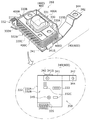
- FIG. 9 is a perspective view showing a configuration example of an assembly unit 350 including the receiving member 330 shown in FIG. 8 and a circuit board 332 on which the receiving member 330 is mounted.
- the receiving member 330 of the assembly unit 350 incorporates an ultrasonic wave receiver 331 as indicated by a broken line.
- the receiving member 330 is mounted on the first surface 332A of the circuit board 332.
- a circuit element 332C, a connector 333, another connector 335, a shield sheet 340 for the circuit board, and the like are provided on the second surface 332B opposite to the circuit board 332, a circuit element 332C, a connector 333, another connector 335, a shield sheet 340 for the circuit board, and the like are provided.
- the shield sheet 340 uses a thin belt-like member having conductivity, such as a flexible printed wiring board, but is not limited thereto. As shown in FIG.
- one end 341 of the shield sheet 340 is fixed with a screw 343.
- One end 341 of the shield sheet 340 is electrically connected to the shield sheet 400.
- the other end 342 of the shield sheet 340 is formed by bending in advance, and the other end 342 is provided with a hole 344 for passing a fastening screw.
- the shield sheet 400 is arranged so as to surround the four side surface portions 330 ⁇ / b> A to 330 ⁇ / b> D of the receiving member 330. That is, the four side portions 400A to 400D of the shield sheet 400 are disposed so as to surround the four side portions 330A to 330D of the receiving member 330, respectively. In this way, the shield sheet 400 surrounds the ultrasonic receiving unit 331 of the receiving member 330 to shield noise generated from an external medical device, and the noise has an adverse effect on the ultrasonic receiving unit 331 and the circuit board 332. Prevent giving.
- FIG. 10 is a perspective view showing the assembly unit 350 shown in FIG. 9 and a part of the outer surface side 5F of the opening / closing cover 5.
- FIG. 11 is a perspective view showing a part of the outer surface side 5 ⁇ / b> F of the opening / closing cover 5. 10 and 11, the decorative plate on the surface of the opening / closing cover 5 is removed, and an exposed portion of the outer surface side 5F of the opening / closing cover 5 is shown.
- a part of the right hinge portion 2H of the opening / closing cover 5 and the right side surface portion 5K are shown.
- a pressing member 320 of the bubble sensor 51 and a pressing member 452 of the upstream closing sensor 52 are arranged side by side in a recess on the inner surface side 5R side opposite to the outer surface side 5F of the opening / closing cover 5. 10 and 11, the position of the pressing member 320 of the bubble sensor 51 and the position of the pressing member 452 of the upstream closing sensor 52 are indicated by broken lines, respectively.
- a shield sheet 410 as a first shielding member is disposed on the outer surface 5 ⁇ / b> F of the opening / closing cover 5 as indicated by hatching.
- the shield sheet 410 is, for example, copper foil, shields noise generated from an external medical device with respect to the ultrasonic wave transmission unit 321 of the bubble sensor 51, and the noise affects the ultrasonic wave transmission unit 321 of the bubble sensor 51. Arranged not to be.
- the arrangement range of the shield sheet 410 is, for example, a range including the position of the pressing member 320 of the bubble sensor 51 and the position of the pressing member 452 of the upstream block sensor 52, but is not particularly limited thereto.
- the ultrasonic wave transmission part 321 of the pressing member 320 of the bubble sensor 51 is electrically connected to one end part 412 of the flexible cable 411.
- the other end 413 of the flexible cable 411 is connected to the connector 333.
- the connector 333 at the other end 413 of the flexible cable 411 is led out from the opening / closing cover 5 toward the lower portion 2B of the main body 2.
- FIG. 12 is a cross-sectional view showing an example of stacking the flexible cable 411 shown in FIG. 10 and the surrounding components.
- the flexible cable 411 is led from the vicinity of the right side of the hinge part 2H on the right side of the opening / closing cover 5 toward the lower part 2B of the main body 2.
- the outer surface portions 414 on both sides of the flexible cable 411 are sandwiched between the two folded portions 384 of the shield member 380.
- the shield member 380 includes, for example, copper foil and, for example, ferrite that is a radio wave absorber, but is not limited thereto.
- the flexible cable 411 and the shield member 380 are covered with black plate-like hidden plates 417 and 418.
- the flexible cable 411 led from the vicinity of the hinge portion 2H on the right side of the opening / closing cover 5 toward the lower portion 2B of the main body 2 is between the opening / closing cover 5 and the lower portion 2B of the main body 2.
- the shield member 380 is covered. Accordingly, the shield member 380 shields noise generated from an external medical device and absorbs radio waves, so that the shield member 380 is flexible cable between the opening / closing cover 5 and the lower portion 2B of the main body 2. 411 prevents noise from appearing.
- FIG. 13A is a perspective view showing a state in which the assembly unit 350 shown in FIG. 9 is disposed in the lower portion 2B of the main body 2, and FIG. 13B is an assembly shown in FIG. It is the perspective view which looked at the unit 350 from the Z direction.
- the circuit board 332 shown in FIG. 13B has screws 349 so that the second surface 332B of the circuit board 332 of the assembly unit 350 is on the upper side. It is fixed to the bottom part 2G inside the main body 2 by using. For this reason, the receiving member 330 shown in FIG. 9 is not visible under the circuit board 332 in FIG. As shown in FIG.
- one end 341 of the shield sheet 340 is electrically connected to the shield sheet 400 on the circuit board 332 side by a screw 343.
- one end 341 of the shield sheet 340 is electrically connected to the shield sheet 400 using a connection portion 341 ⁇ / b> S.
- the other end 342 of the shield sheet 340 is electrically connected and fixed to the ground terminal 361 in the main body 2 using a fastening screw 360.
- the shield sheet 410 on the opening / closing cover 5 side has an electrical connection portion 410G shown in FIG.
- the electrical connection portion 410G on the opening / closing cover 5 side is led out from the shield sheet 410 toward the lower portion 2B of the main body 2 and has a tip portion 410T.
- the leading end portion 410T of the electrical connection portion 410G shown in FIG. 10 is guided into the lower portion 2B of the main body 2 by passing through the gap portion 399 provided in the lower portion 2B of the main body 2.
- the tip 410T is electrically connected and fixed to the ground terminal 361 in the main body 2 using a fastening screw 360.
- the shield sheet 410, its electrical connection portion 410G, and the shield member 380 shown in FIG. 10 are first shielding members that shield noise from the outside with respect to the ultrasonic wave transmitting unit 321.
- the shield sheet 400 shown in FIG. 10 and the shield sheet 340 shown in FIG. 13 are the second that surrounds almost the entire surface so as to shield noise from the outside except the receiving surface of the ultrasonic wave receiving unit 331. It is a shielding member.
- the first shielding member and the second shielding member constitute a noise shielding unit 800.
- the end portion 381 of the shield member 380 shown in FIG. 10 is electrically connected and fixed to the ground terminal 361 in the main body 2 using a fastening screw 360 as shown in FIG. 13B. ing.
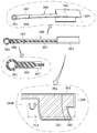
- the shield member 380 includes a copper foil 382 and a coating film 383 having electrical insulation properties that covers the copper foil 382.
- the shield member 380 has a folded portion 384. A flexible cable 411 is inserted into the bi-folded portion 384, and the bi-folded portion 384 is folded at the folding line 380P. The portion 384 is prevented from opening.
- a portion 386 near the terminal 381 of the shield member 380 is also covered with a tape 387 having electrical insulation and heat resistance.
- ferrite which is a radio wave absorber, is disposed on the copper foil 382 of the shield member 380.
- FIG. 9 to 15 shows an example in which the noise shielding unit 800 is connected to the ground terminal 361.
- a shield sheet 410 is fixed to the exposed portion of the outer surface 5 ⁇ / b> F of the opening / closing cover 5.
- the flexible cable 411 is electrically connected to the ultrasonic transmission unit 321 or the like.
- the flexible cable 411 passes through the folded portion 384 of the shield member 380 shown in FIG. 14, so that the shield member 380 covers the flexible cable 411 as shown in FIG. 10.
- the tip 410T of the electrical connection portion 401G of the shield sheet 410, the shield member 380, and the flexible cable 411 are formed from the outside of the main body 2 shown in FIG.
- the connector 333 of the flexible cable 411 is fitted into the connector receiver of the circuit board 332 so that the ultrasonic transmission unit 321 is electrically connected to the circuit board 332.
- a fastening screw 360 is used to electrically fix and fix to the ground terminal 361 of the boss 2S provided on the lower portion 2B of the main body 2.
- the ultrasonic wave transmitting portion 321 in the pressing member 320 of the bubble sensor 51 is attached to the shield sheet 410 covering the outer surface side of the opening / closing cover 5 and the flexible cable 411.
- the shield sheet 410 and the shield member 380 are first shielding members that shield the ultrasonic transmission unit 321 from noise of medical equipment such as an electric knife.
- the assembly unit 350 including the receiving member 330 having the ultrasonic receiving unit 331 shown in FIG. 9 and the circuit board 332 on which the receiving member 330 is mounted surrounds the ultrasonic receiving unit 331.
- the shield sheet 400 and the shield sheet 340 illustrated in FIG. 10 are second shielding members that shield the ultrasonic receiving unit 331 and the circuit board 332 from noise of a medical device such as an electric knife.
- the first shielding member and the second shielding member constitute a noise shielding unit 800.
- the opening / closing cover 5 and the lower part 2B of the main body 2 are connected by a hinge 2H.
- a shield member 380 is superimposed on the flexible cable 411. Since it is arrange
- the ultrasonic wave transmission unit 321 and the ultrasonic wave reception unit 331 of the bubble sensor 51 can shield radio wave noise generated by an external medical device such as an electric knife, so that the bubble noise 51 is bubbled in the infusion tube 200.
- an electric knife so that the bubble noise 51 is bubbled in the infusion tube 200.
- movement at the time of using the infusion pump 1 mentioned above is demonstrated.
- the infusion tube setting direction display unit 150 is viewed to visually set the infusion tube 200. I can confirm.
- the medical worker opens the opening / closing cover 5 and fits the upstream side 200A of the infusion tube 200 toward the first infusion tube guide part 54 side of the right side toward the main body lower part 1B, and the downstream side 200B of the infusion tube 200. Is inserted into the second infusion tube guide 55 side of the left part of the main body lower part 1B.
- the medical worker can set the infusion tube 200 correctly with respect to the infusion pump 1 along the T direction.
- the medical worker converts the infusion tube 200 shown in FIG. 4 into the first infusion tube guide portion 54, the bubble sensor 51, the upstream occlusion sensor 52, the liquid feeding drive portion 60, the downstream occlusion sensor 53, the tube clamp portion 270, and the first 2 Can be set in the T direction along the infusion tube guide portion 55.
- the open / close cover 5 has a bubble sensor 51, an upstream block sensor 52, a downstream block sensor 53, and a liquid feeding drive unit 60.
- the tube clamp part 270 is covered.
- the medicine can be fed along the T direction through the infusion tube 200.
- the medical staff can operate the operation buttons on the operation panel unit 4 while checking the information on the display unit 3 on the upper part of the main body cover 2.
- the infusion pump 1 of the embodiment of the present invention includes the main body 2 and the tube mounting portion 50 that is disposed in the main body 2 and in which the infusion tube 200 that infuses the medicine to the patient P side is mounted in the lateral direction.
- the infusion tube 200 is pressurized to feed the medicine in the infusion tube laterally, and the main body 2 is closed and covers the infusion tube 200 attached to the tube attachment part 50 by closing, the bubble sensor 51 for detecting bubbles in the infusion tube 200 attached to the tube attachment part 50, and the bubble sensor
- a noise shielding unit 800 that shields noise from the outside is provided.
- the noise shielding unit 800 that shields noise from the outside with respect to the bubble sensor 51 is included, the bubble sensor 51 is not adversely affected by noise from the outside by the noise shielding unit, and the noise from the medical device is not affected. It is possible to prevent erroneous detection of the presence or absence of bubbles.
- the bubble sensor 51 includes an ultrasonic wave transmitting unit 321 and an ultrasonic wave receiving unit 331 configured to receive the ultrasonic wave from the ultrasonic wave from the ultrasonic wave generating unit 331 through the infusion tube 200 and the pressing unit 320 disposed on the opening / closing cover 5.
- the noise shielding unit 800 is a first shielding member that shields noise against the ultrasonic wave transmission unit 321 of the pressing member 320, for example, a shield sheet 410, and a receiving member 330 disposed in the main body 2
- the shield member 400 includes a shield sheet 400 and a shield sheet 340 which are second shield members that shield noise from the ultrasonic wave receiving unit 331 of the receiving member 330.
- the ultrasonic wave transmission part 321 of the bubble sensor 51 shields noise by the first shielding member, and the ultrasonic wave reception part 331 of the bubble sensor 51 can shield noise by the second shielding member, the ultrasonic wave transmission part. Neither 321 nor the ultrasonic wave receiving unit 331 is affected by noise.
- the first shielding member and the second shielding member are connected to a ground terminal in the main body. For this reason, since both the 1st shielding member and the 2nd shielding member are connected to the ground terminal 361 in the main body 2, the 1st shielding member and the 2nd shielding member can shield the external noise with respect to a bubble sensor.
- a shield member 380 for shielding noise is disposed on the flexible cable 411 that is connected to the ultrasonic wave transmitting portion 321 of the opening / closing cover 5 and guided into the main body 2. Thereby, the external noise which the flexible cable 411 enters through the clearance gap between the opening-and-closing cover 5 and the main body 2 can be shielded, and noise can be prevented from being placed on the flexible cable 411.
- the display unit 3 and the operation panel unit 4 are arranged, and in the lower part 2B of the main body 2, a tube mounting part 50, a liquid feeding drive part 60 and an opening / closing cover 5 are arranged. Therefore, a medical worker can close the open / close cover 5 by mounting the infusion tube 200 on the tube mounting portion 50 while confirming information on the display portion 3 of the upper portion 2A of the main body 2. Then, the medical staff can operate the operation buttons on the operation panel unit 4 while confirming information on the display unit 3 of the upper portion 2A of the main body 2.
- the infusion tube 200 is set along the T direction, which is the horizontal direction, by the tube mounting portion 50, but not limited thereto, for example, the tube mounting portion 50 includes the infusion tube 200.
- the tube mounting portion 50 includes the infusion tube 200.
- a structure may be adopted in which the unit is inclined and set in the lateral direction so as to be lowered by a predetermined angle from the upstream side 200A to the downstream side 200B.
Landscapes
- Health & Medical Sciences (AREA)
- Heart & Thoracic Surgery (AREA)
- Vascular Medicine (AREA)
- Engineering & Computer Science (AREA)
- Anesthesiology (AREA)
- Biomedical Technology (AREA)
- Hematology (AREA)
- Life Sciences & Earth Sciences (AREA)
- Animal Behavior & Ethology (AREA)
- General Health & Medical Sciences (AREA)
- Public Health (AREA)
- Veterinary Medicine (AREA)
- Emergency Medicine (AREA)
- Infusion, Injection, And Reservoir Apparatuses (AREA)
Description
本発明は、患者へ薬剤等を送液するための輸液ポンプに関する。特にヒンジにより回動可能に支持され、輸液ポンプ本体のチューブ装着部に装着された輸液チューブを覆う開閉カバーにまで電気配線が延設された輸液ポンプに関する。
輸液ポンプは、例えば集中治療室(ICU)等で使用されて、患者に対して薬剤の送液処置を、高い精度で比較的長時間行うことに用いられている。輸液ポンプの上には所定の薬剤バッグ(輸液バッグ)が配置され、本体と開閉扉との間には、薬剤バッグから下げた輸液チューブを挟みこんで、この輸液チューブを本体内に収容して開閉扉を閉じることで保持している。輸液ポンプの本体内では、定位置にセットされた輸液チューブの外周面が、本体内の複数のフィンガと開閉扉の内面との間に挟まれている。この輸液ポンプは、送液駆動部の複数のフィンガが個別駆動されることで、複数のフィンガが輸液チューブの外周面を長さ方向に沿って順次押圧して薬剤の送液を行う蠕動式輸液ポンプである (特許文献1を参照)。
特許文献1に記載の輸液ポンプでは、輸液チューブを輸液ポンプの本体内において上から下に向けて垂直に通して保持している。これに対して、輸液チューブを輸液ポンプの本体内において水平方向に通して保持する輸液ポンプが提案されている。このように、輸液チューブを輸液ポンプの本体において水平方向に通して保持する構造を採用しようとするのは、輸液チューブが輸液ポンプの本体内を上から下に向けて垂直に通っている輸液ポンプとは異なり、複数の輸液ポンプを上下位置にスタックした状態で重ねて保持しても輸液チューブが邪魔にならないという利点があるからである。例えば、輸液ポンプの本体に対して向かって右側部分に輸液チューブの上流側が配置され、輸液ポンプの本体に対して向かって左側部分に輸液チューブの下流側が配置されるように予め決められている。この場合には、輸液チューブの上流側を輸液ポンプの本体の右側部分に配置し、輸液チューブの下流側を輸液ポンプの本体の左側部分に配置すれば、送液駆動部が駆動することで、薬剤が上流側から下流側に向かって予め定めた送液方向に沿って送液でき、患者に対して正しく送液できる。
ところで、輸液ポンプは、輸液チューブ内に気泡が存在しているかどうかを検出する気泡センサを有している。輸液ポンプは、上述したように例えば集中治療室(ICU)等で使用されるが、気泡センサは、例えば電気メス等の医療器具からノイズを受けることがある。気泡センサがノイズを受けると、気泡の有無の誤検出を起こすおそれがある。
そこで、本発明は、医療機器からのノイズを防いで、気泡の有無の誤検出を防ぐことができる輸液ポンプを提供することを目的とする。
そこで、本発明は、医療機器からのノイズを防いで、気泡の有無の誤検出を防ぐことができる輸液ポンプを提供することを目的とする。
本発明の輸液ポンプは、本体と、前記本体内に配置されて、薬剤を患者側に輸液する輸液チューブを装着するチューブ装着部と、前記本体内に配置されて、前記輸液チューブを前記チューブ装着部に装着した状態で、前記輸液チューブを加圧して前記輸液チューブ中の前記薬剤を前記横方向に送液する送液駆動部と、前記本体に取り付けられ、閉じることで前記チューブ装着部に装着した前記輸液チューブを覆う開閉カバーと、前記チューブ装着部に装着された前記輸液チューブ内の気泡を検出するための超音波発信部及び超音波受信部からなる気泡センサと、を備え、前記超音波発信部及び前記超音波受信部に対する外部からのノイズを遮蔽するノイズ遮蔽部と、を有することを特徴とする。
上記構成によれば、気泡センサに対する外部からのノイズを遮蔽するノイズ遮蔽部を有しているので、気泡センサは、ノイズ遮蔽部により、外部からのノイズによる悪影響を受けず、医療機器からのノイズを防いで、気泡の有無の誤検出を防ぐことができる。
上記構成によれば、気泡センサに対する外部からのノイズを遮蔽するノイズ遮蔽部を有しているので、気泡センサは、ノイズ遮蔽部により、外部からのノイズによる悪影響を受けず、医療機器からのノイズを防いで、気泡の有無の誤検出を防ぐことができる。
好ましくは、前記気泡センサは、前記超音波発信部を備えて前記開閉カバーに配置された押し当て部材と、前記超音波発信部からの超音波を前記輸液チューブに通して受信する超音波受信部を備えて前記本体内に配置された受け部材とを有し、前記ノイズ遮蔽部は、前記押し当て部材の前記超音波発信部に対するノイズを遮蔽する第1遮蔽部材と、前記受け部材の前記超音波受信部に対するノイズを遮蔽する第2遮蔽部材とを有することを特徴とする。
上記構成によれば、気泡センサの超音波発信部は、第1遮蔽部材によりノイズを遮蔽し、気泡センサの超音波受信部は、第2遮蔽部材によりノイズを遮蔽できるので、超音波発信部と超音波受信部のいずれもノイズの影響を受けない。
上記構成によれば、気泡センサの超音波発信部は、第1遮蔽部材によりノイズを遮蔽し、気泡センサの超音波受信部は、第2遮蔽部材によりノイズを遮蔽できるので、超音波発信部と超音波受信部のいずれもノイズの影響を受けない。
好ましくは、前記第1遮蔽部材と前記第2遮蔽部材は、前記本体内のグランド端子に接続されていることを特徴とする。
上記構成によれば、第1遮蔽部材と第2遮蔽部材は、共に本体内のグランド端子に接続しているので、第1遮蔽部材と第2遮蔽部材は気泡センサに対する外部のノイズを遮蔽できる。
好ましくは、前記開閉カバーの前記超音波発信部に接続されて前記本体部内に導かれているフレキシブルケーブルには、ノイズ遮蔽用のシールド部材が配置されていることを特徴とする。
上記構成によれば、フレキシブルケーブルが開閉カバーと本体との隙間を通じて入る外部のノイズを遮蔽することができ、フレキシブルカーブルにノイズが載るのを防ぐことができる。
上記構成によれば、第1遮蔽部材と第2遮蔽部材は、共に本体内のグランド端子に接続しているので、第1遮蔽部材と第2遮蔽部材は気泡センサに対する外部のノイズを遮蔽できる。
好ましくは、前記開閉カバーの前記超音波発信部に接続されて前記本体部内に導かれているフレキシブルケーブルには、ノイズ遮蔽用のシールド部材が配置されていることを特徴とする。
上記構成によれば、フレキシブルケーブルが開閉カバーと本体との隙間を通じて入る外部のノイズを遮蔽することができ、フレキシブルカーブルにノイズが載るのを防ぐことができる。
好ましくは、前記本体の上部分には、前記表示部と前記操作パネル部が配置され、前記本体の下部分には、前記チューブ装着部と前記送液駆動部と前記開閉カバーが配置されていることを特徴とする。
上記構成によれば、医療従事者は、本体の上部分の表示部の情報を確認しながら、チューブ装着部への輸液チューブの装着を行って、開閉カバーを閉じることができる。そして、医療従事者は、本体の上部分の表示部の情報を確認しながら、操作パネル部の操作ボタンを操作することができる。
上記構成によれば、医療従事者は、本体の上部分の表示部の情報を確認しながら、チューブ装着部への輸液チューブの装着を行って、開閉カバーを閉じることができる。そして、医療従事者は、本体の上部分の表示部の情報を確認しながら、操作パネル部の操作ボタンを操作することができる。
本発明は、医療機器からのノイズを防いで、気泡の有無の誤検出を防ぐことができる輸液ポンプを提供することができる。
以下に、本発明の好ましい実施形態を、図面を参照して詳しく説明する。
尚、以下に述べる実施の形態は、本発明の好適な具体例であるから、技術的に好ましい種々の限定が付されているが、本発明の範囲は、以下の説明において特に本発明を限定する旨の記載がない限り、これらの態様に限られるものではない。
図1は、本発明の輸液ポンプの好ましい実施形態を示す斜視図である。図2は、図1に示す輸液ポンプをW方向から見た斜視図である。
尚、以下に述べる実施の形態は、本発明の好適な具体例であるから、技術的に好ましい種々の限定が付されているが、本発明の範囲は、以下の説明において特に本発明を限定する旨の記載がない限り、これらの態様に限られるものではない。
図1は、本発明の輸液ポンプの好ましい実施形態を示す斜視図である。図2は、図1に示す輸液ポンプをW方向から見た斜視図である。
図1と図2に示す輸液ポンプ1は、例えば集中治療室(ICU、CCU,NICU)等で使用され、患者に対して、例えば抗がん剤、麻酔剤、化学療法剤、輸血等、栄養剤等の薬剤の微量注入処置を、高い精度で比較的長時間行うことに用いられる微量持続注入ポンプである。この輸液ポンプ1は、例えば薬剤ライブラリから使用する薬剤を選択して、その選択した薬剤を送液するために用いられる。この薬剤ライブラリは、薬剤ライブラリデータベース(DB)において、予め登録された薬剤名を含む薬剤の投与設定群である薬剤情報である。医療従事者は、この薬剤ライブラリを用いることにより、複雑な投与設定をその都度行わなくても良く、薬剤の選択および薬剤の設定が図れる。
図2に示すように、輸液ポンプ1は、薬剤171を充填した薬剤バッグ170から、クレンメ179と輸液チューブ200と留置針172を介して、患者Pに対して正確に送液することができる。薬剤は輸液剤ともいう。輸液チューブは輸液ラインともいう。
輸液ポンプ1は、本体カバー2と取手2Tを有しており、取手2TはN方向に伸ばしたりT方向に収納したりすることができる。この本体カバー2は、本体ともいい、耐薬品性を有する成型樹脂材料により一体成型されており、仮に薬剤等がかかっても輸液ポンプ1の内部に侵入するのを防ぐことができる防滴処理構造を有している。このように、本体カバー2が防滴処理構造を有しているのは、上方に配置されている薬剤バッグ170内の薬剤171がこぼれ落ちたり、周辺で用いる消毒液等が飛散して付着することがあるためである。
輸液ポンプ1は、本体カバー2と取手2Tを有しており、取手2TはN方向に伸ばしたりT方向に収納したりすることができる。この本体カバー2は、本体ともいい、耐薬品性を有する成型樹脂材料により一体成型されており、仮に薬剤等がかかっても輸液ポンプ1の内部に侵入するのを防ぐことができる防滴処理構造を有している。このように、本体カバー2が防滴処理構造を有しているのは、上方に配置されている薬剤バッグ170内の薬剤171がこぼれ落ちたり、周辺で用いる消毒液等が飛散して付着することがあるためである。
まず、輸液ポンプ1の本体カバー2に配置された要素について説明する。
図1と図2に示すように、本体カバー2の上部分2Aには、表示部3と、操作パネル部4が配置されている。表示部3は、画像表示装置であり、例えばカラー液晶表示装置を用いている。この表示部3は、日本語表記による情報表記だけでなく、必要に応じて複数の外国語による情報の表示を行うことができる。表示部3は、本体カバー2の上部分2Aの左上位置であって、開閉カバー5の上側に配置されている。
図1と図2に示すように、本体カバー2の上部分2Aには、表示部3と、操作パネル部4が配置されている。表示部3は、画像表示装置であり、例えばカラー液晶表示装置を用いている。この表示部3は、日本語表記による情報表記だけでなく、必要に応じて複数の外国語による情報の表示を行うことができる。表示部3は、本体カバー2の上部分2Aの左上位置であって、開閉カバー5の上側に配置されている。
本体カバー2の上部分2Aは、本体カバー2の上半分の部分である。本体カバー2の下部分2Bは、本体カバー2の下半分の部分である。図2では、表示部3には、一例として薬剤投与の予定量(mL)の表示欄3B、薬剤投与の積算量(mL)の表示欄3C、充電履歴の表示欄3D、流量(mL)の表示欄3E等が表示されているが、図1に示す表示部3ではこれらの表示内容の図示は、図面の簡単化のために省略している。表示部3は、この他に警告メッセージを表示することもできる。
操作パネル部4は、本体カバー2の上部分2Aにおいて表示部3の右側に配置され、操作パネル部4には、操作ボタンとしては、図示例では、例えばパイロットランプ4A、早送りスイッチボタン4B、開始スイッチボタン4C、停止スイッチボタン4D、メニュー選択ボタン4E、電源スイッチ4F等が配置されている。
図1に示すように、本体カバー2の下部分2Bには、蓋部材としての開閉カバー5が回転軸5Aを中心として、R方向に開閉可能に設けられている。開閉カバー5は、X方向に沿って長く形成されている板状の蓋部材である。チューブ装着部50と送液駆動部60は、開閉カバー5の内側に配置されている。このチューブ装着部50には、例えば軟質塩化ビニル等の可撓性の熱可塑性樹脂製の輸液チューブ200をセットして、この開閉カバー5を閉じることで、輸液チューブ200は、チューブ装着部50において、X方向(T方向)に沿って水平に装着できる。
なお、図1と図2におけるX方向、Y方向、Z方向は互いに直交しており、Z方向は上下方向である。X方向は、送液方向であるT方向と平行であり輸液ポンプ1の左右方向である。Y方向は、輸液ポンプ1の前後方向である。
なお、図1と図2におけるX方向、Y方向、Z方向は互いに直交しており、Z方向は上下方向である。X方向は、送液方向であるT方向と平行であり輸液ポンプ1の左右方向である。Y方向は、輸液ポンプ1の前後方向である。
図3では、図1と図2に示す輸液ポンプ1の開閉カバー5を開いて、輸液チューブ200を装着するためのチューブ装着部50と送液駆動部60が示されている。
図3に示すように、チューブ装着部50と送液駆動部60は、輸液ポンプ1の本体下部1B(本体カバー2の下部分2B)に設けられており、チューブ装着部50と送液駆動部60は、表示部3と操作パネル部4の下部においてX方向に沿って設けられている。チューブ装着部50と送液駆動部60は、図2に示すように開閉カバー5を、回転軸5Aを中心としてCR方向に閉じると開閉カバー5により覆うことができる。
図3に示すように、チューブ装着部50と送液駆動部60は、輸液ポンプ1の本体下部1B(本体カバー2の下部分2B)に設けられており、チューブ装着部50と送液駆動部60は、表示部3と操作パネル部4の下部においてX方向に沿って設けられている。チューブ装着部50と送液駆動部60は、図2に示すように開閉カバー5を、回転軸5Aを中心としてCR方向に閉じると開閉カバー5により覆うことができる。
医療従事者は、本体カバー2の上部分2Aの表示部3の情報を確認しながら、チューブ装着部50への輸液チューブ200の装着を行って、開閉カバー5を閉じることができる。そして、医療従事者は、本体カバー2の上部分2Aの表示部3の情報を確認しながら、操作パネル部4の操作ボタンを操作することができる。これにより、医療現場において、輸液ポンプ1の操作性を向上することができる。
図3に示すように、チューブ装着部50は、気泡センサ51と、上流閉塞センサ52と、下流閉塞センサ53と、チューブクランプ部270と、右側位置の第1輸液チューブガイド部54と、左側位置の第2輸液チューブガイド部55を有している。
図3に示すように、チューブ装着部50は、気泡センサ51と、上流閉塞センサ52と、下流閉塞センサ53と、チューブクランプ部270と、右側位置の第1輸液チューブガイド部54と、左側位置の第2輸液チューブガイド部55を有している。
図3に示すように、チューブ装着部50の付近には、輸液チューブ200をセットする際に、正しい送液方向であるT方向を明確に表示するための輸液チューブ設定方向表示部150が設けられている。この輸液チューブ設定方向表示部150は、例えば複数の矢印151により構成されている。輸液チューブ設定方向表示部150は、例えばチューブ装着部50の下部に直接印刷しても良いし、シール状の部材に印刷したものをチューブ装着部50の下部に貼り付けても良い。輸液チューブ設定方向表示部150は、開閉カバー5の内側にセットされた輸液チューブ200による薬剤171の正しい方向の送液方向(T方向)を明示するために配置されている。
これにより、医療従事者が、図3の開閉カバー5をCS方向に開けて、チューブ装着部50を開放して、このチューブ装着部50に対して輸液チューブ200を装着する際に、輸液チューブ200による薬剤の送液方向であるT方向を明示できる。このため、医療従事者は、目視で確認しながら、誤って輸液チューブ200を逆方向に装着してしまうことを防ぐことができる。
これにより、医療従事者が、図3の開閉カバー5をCS方向に開けて、チューブ装着部50を開放して、このチューブ装着部50に対して輸液チューブ200を装着する際に、輸液チューブ200による薬剤の送液方向であるT方向を明示できる。このため、医療従事者は、目視で確認しながら、誤って輸液チューブ200を逆方向に装着してしまうことを防ぐことができる。
次に、図3に示す開閉カバー5の構造例を説明する。
図3に示すように、開閉カバー5は、輸液ポンプ1を軽量化するために、薄い成型樹脂部材により作られている板状の部材である。これにより、開閉カバー5の重量を軽減でき、構造を簡単化することができる。開閉カバー5がチューブ装着部50と送液駆動部60を覆うことができるようにするために、開閉カバー5は、回転軸5Aを中心としてCS方向とCR方向に沿って開閉可能である。すなわち、開閉カバー5は、2つのヒンジ部2H、2Hを用いて、本体カバー2の本体下部2Bに対して支持されている。2つのヒンジ部2H、2Hは、第1フック部材5Dと第2フック部材5Eにそれぞれ対応して配置されている。
図3に示すように、開閉カバー5は、輸液ポンプ1を軽量化するために、薄い成型樹脂部材により作られている板状の部材である。これにより、開閉カバー5の重量を軽減でき、構造を簡単化することができる。開閉カバー5がチューブ装着部50と送液駆動部60を覆うことができるようにするために、開閉カバー5は、回転軸5Aを中心としてCS方向とCR方向に沿って開閉可能である。すなわち、開閉カバー5は、2つのヒンジ部2H、2Hを用いて、本体カバー2の本体下部2Bに対して支持されている。2つのヒンジ部2H、2Hは、第1フック部材5Dと第2フック部材5Eにそれぞれ対応して配置されている。
図3に示すように、開閉カバー5の表面側には、右上部分に開閉操作レバー260が設けられている。開閉カバー5の内面側には、輸液チューブ押さえ部材500と、第1フック部材5Dと第2フック部材5Eが設けられている。この輸液チューブ押さえ部材500は、X方向に沿って長く矩形状かつ面状の突出部として配置されており、輸液チューブ押さえ部材500は、送液駆動部60に対面する位置にある。輸液チューブ押さえ部材500は、送液駆動部60に沿ってX方向に平坦面を有しており、輸液チューブ押さえ部材500は、開閉カバー5をCR方向に閉じることで、送液駆動部60との間で輸液チューブ200の一部分を押し付けて挟むようになっている。
医療従事者は、表示部3に表示されている表示内容を確認しながら、輸液チューブ200を輸液ポンプ1の本体の下半分の部分に水平方向に沿ってセットでき、輸液チューブ200がチューブ装着部50と送液駆動部60にセットされた後に、図1と図2に示すように開閉カバー5をCR方向に閉じることで、輸液チューブ200を覆うことができる。
医療従事者は、表示部3に表示されている表示内容を確認しながら、輸液チューブ200を輸液ポンプ1の本体の下半分の部分に水平方向に沿ってセットでき、輸液チューブ200がチューブ装着部50と送液駆動部60にセットされた後に、図1と図2に示すように開閉カバー5をCR方向に閉じることで、輸液チューブ200を覆うことができる。
図3に示すように、第1フック部材5Dと第2フック部材5Eは、本体下部1B側の固定部分1D、1Eに対してそれぞれ機械的に同時に掛かることにより、開閉カバー5は、図2に示すように、本体下部1Bのチューブ装着部50と送液駆動部60を閉鎖した状態に保持する。この第1フック部材5Dと第2フック部材5Eと、本体下部1B側の固定部分1D、1Eは、開閉カバー5のダブルフック構造部300を構成している。
図3に示すチューブクランプ部270は、開閉カバー5を閉じることにより、輸液チューブ200の途中部分をクランプして閉塞させる。チューブクランプ部270は、左側の固定部分1Eの近傍であって、左側の第2フック部材5Eに対応する位置に配置されている。医療従事者が輸液チューブ200をX方向に水平にセットして、医療従事者が開閉カバー5をCR方向に閉じると、チューブクランプ部270は、輸液チューブ200の途中の一部分を閉塞できる。
図3に示すように、第1輸液チューブガイド部54は、本体下部1Bおいて向かって右側部分に設けられ、第2輸液チューブガイド部55は、本体下部1Bにおいて向かって左側部分に設けられている。第1輸液チューブガイド部54は、輸液チューブ200の上流側200Aをはめ込むことで保持でき、第2輸液チューブガイド部55は、輸液チューブ200の下流側200Bをはめ込むことで保持でき、輸液チューブ200をX方向に沿って水平方向に保持するようになっている。このように、水平方向に保持された輸液チューブ200は、気泡センサ51と、上流閉塞センサ52と、送液駆動部60と、下流閉塞センサ53と、そしてチューブクランプ部270に沿って、T方向に沿ってはめ込んで固定される。
図3に示すように、第1輸液チューブガイド部54は、2つの突起54B,54Cと、傾斜案内部54Tを有している。2つの突起54B,54Cは、輸液チューブ200を水平方向にセットする際に、輸液チューブ200の上流側200Aを着脱可能に挟んで保持するために、本体下部1Bに形成されている。傾斜案内部54Tは、2つの突起54B、54Cから斜め右上方向に向かって形成され、輸液チューブ200の上流側200Aを斜め上方に案内する。
この傾斜案内部54Tを設けることにより、医療従事者は、輸液チューブ200の上流側200Aがこの傾斜案内部54T側にセットされることを、視覚的に確認することができるばかりでなく、輸液チューブ200の上流側200Aは急激に曲げないようにして保持することができる。また、この傾斜案内部54Tが開閉カバー5により覆われずに露出しているので、医療従事者はこの傾斜案内部54Tを直接目視することで、輸液チューブ200の上流側200Aを傾斜案内部54T側に配置すれば良いことを確認できる。
この傾斜案内部54Tを設けることにより、医療従事者は、輸液チューブ200の上流側200Aがこの傾斜案内部54T側にセットされることを、視覚的に確認することができるばかりでなく、輸液チューブ200の上流側200Aは急激に曲げないようにして保持することができる。また、この傾斜案内部54Tが開閉カバー5により覆われずに露出しているので、医療従事者はこの傾斜案内部54Tを直接目視することで、輸液チューブ200の上流側200Aを傾斜案内部54T側に配置すれば良いことを確認できる。
図3に示すように、第2輸液チューブガイド部55は、輸液チューブ200の下流側200Bの一部分を着脱可能に挟んで保持するために、本体下部1Bの側面部分1Sに形成された溝部分である。第1輸液チューブガイド部54と第2輸液チューブガイド部55は、輸液チューブ200を開閉カバー5とチューブ装着部50との間に挟み込んで潰してしまうことが無いように、チューブ装着部50内に確実に装着できる。図1と図2に示すように、開閉カバー5の右側の側面部5Kは、斜め左上方向に向かって傾斜して形成されている。これにより、開閉カバー5を閉じて状態であっても、開閉カバー5が第1輸液チューブガイド部54の2つの突起54B,54Cと、傾斜案内部54Tの上にかぶらないようにしている。
図3に示す気泡センサ51は、輸液チューブ200内に生じる気泡(空気)を検出するセンサであり、例えば気泡センサ51は、軟質塩化ビニルなどの輸液チューブ200の外側から、輸液チューブ200内に流れる薬剤中に含まれる気泡を監視する超音波センサである。超音波センサの超音波発信部から発生する超音波を輸液チューブ200内に流れる薬剤に当てることで、薬剤における超音波の透過率と、気泡における超音波の透過率とが異なることから、超音波受信部は、その透過率の差を検出して気泡の有無を監視する。気泡センサ51は、押し当て部材320と受け部材330を有している。後で説明するが、超音波発信部は開閉カバー5側の押し当て部材320に配置されている。超音波受信部は本体2側の受け部材330に配置されている。これを前提にして、以下に詳述するが、これとは逆に、超音波受信部を開閉カバー5側の押し当て部材320に配置し、超音波発信部を本体2側の受け部材330に配置してもよいが、ノイズを遮蔽するための超音波受信部の遮蔽を施して、押し当て部材320に配置する構造が複雑になる。
図3に示す上流閉塞センサ52は、輸液チューブ200の上流側200Aにおいて輸液チューブ200内が閉塞しているかどうかを検出するセンサであり、下流閉塞センサ53は、輸液チューブ200の下流側200Bにおいて輸液チューブ200内が閉塞しているかどうかを検出するセンサである。上流閉塞センサ52と下流閉塞センサ53は、同じ構成である。輸液チューブ200が閉塞する場合としては、例えば送液しようとする薬剤の粘度が高いか、薬剤の濃度が高い等の場合である。
図3に示すように、開閉カバー5の内面側には、上流閉塞センサ52と下流閉塞センサ53の対応する位置に、それぞれ押圧部材452、453が設けられている。医療従事者が、図3に示すようにチューブ装着部50に輸液チューブ200をセットした後に、図2に示すように開閉カバー5を閉じると、開閉カバー5側の押圧部材452と押圧部材453が輸液チューブ200の一部分を上流側閉塞センサ52と下流側閉塞センサ53側にそれぞれ押し当てることができる。このため、直径が異なる複数種類の輸液チューブ200の内の何れのサイズの輸液チューブ200が輸液ポンプ1に装着されても、開閉カバー5を閉じると上流側閉塞センサ52と下流側閉塞センサ53は、輸液チューブ200の閉塞状態を検出できる。
図4は、輸液ポンプ1の電気的な構成例を示している。
図4に示すように、送液駆動部60は、駆動モータ61と、この駆動モータ61により回転駆動される複数個のカムを有するカム構造体62と、このカム構造体62の各カムにより移動される複数のフィンガを有するフィンガ構造体63を有している。
カム構造体62は、複数のカム、例えば6個のカム62A~62Fを有しており、フィンガ構造体63は、6個のカム62A~62Fに対応して6個のフィンガ63A~63Fを有している。6個のカム62A~62Fは互いに位相差を付けて配列されており、カム構造体62は、駆動モータ61の出力軸61Aに連結されている。
図4に示すように、送液駆動部60は、駆動モータ61と、この駆動モータ61により回転駆動される複数個のカムを有するカム構造体62と、このカム構造体62の各カムにより移動される複数のフィンガを有するフィンガ構造体63を有している。
カム構造体62は、複数のカム、例えば6個のカム62A~62Fを有しており、フィンガ構造体63は、6個のカム62A~62Fに対応して6個のフィンガ63A~63Fを有している。6個のカム62A~62Fは互いに位相差を付けて配列されており、カム構造体62は、駆動モータ61の出力軸61Aに連結されている。
図4に示す制御部100の指令により、駆動モータ61の出力軸61Aが回転すると、6個のフィンガ63A~63Fが予め定めた順番にY方向に所定ストローク分進退することで、輸液チューブ200はT方向に沿って開閉カバー5の輸液チューブ押さえ部材500に対して押し付けられる。このため、輸液チューブ200内の薬剤は、T方向に送液することができる。すなわち、複数のフィンガ63A~63Fが個別駆動されることで、複数のフィンガ63A~63Fが輸液チューブ200の外周面をT方向に沿って順次押圧して輸液チューブ200内の薬剤の送液を行う。複数のフィンガ63A~63Fの蠕動運動を制御することにより、フィンガ63A~63Fを順次前後進させ、あたかも波動が進行するようにして、輸液チューブ200の閉塞点をT方向に移動させることで、輸液チューブ200をしごいて薬剤を移送する。
図4に示すように、輸液ポンプ1は、全体的な動作の制御を行う制御部(コンピュータ)100を有している。この制御部100は、例えばワンチップのマイクロコンピュータであり、ROM(読み出し専用メモリ)101,RAM(ランダムアクセスメモリ)102、不揮発性メモリ103、そしてクロック104を有する。クロック104は、所定の操作により現在時刻の修正ができ、現在時刻の取得や、所定の送液作業の経過時間の計測、送液の速度制御の基準時間の計測等ができる。
図4に示す制御部100は、電源スイッチボタン4Fと、スイッチ111が接続されている。スイッチ111は、電源コンバータ部112と例えばリチウムイオン電池のような充電池113を切り換えることで、電源コンバータ部112と充電池113のいずれかから制御部100に電源供給する。電源コンバータ部112は、コンセント114を介して商用交流電源115に接続されている。
図4に示す制御部100は、電源スイッチボタン4Fと、スイッチ111が接続されている。スイッチ111は、電源コンバータ部112と例えばリチウムイオン電池のような充電池113を切り換えることで、電源コンバータ部112と充電池113のいずれかから制御部100に電源供給する。電源コンバータ部112は、コンセント114を介して商用交流電源115に接続されている。
図4の表示部ドライバ130は、制御部100の指令により表示部3を駆動して、図2に例示する情報内容や警告メッセージを表示する。スピーカ131は、制御部100の指令により各種の警報内容を音声により告知することができる。ブザー132は、制御部100の指令により各種の警報を音により告知することができる。スピーカ131は、輸液チューブ200が誤った方向であるN方向(逆方向)にセットされた場合に、医療従事者に対して音声により警告を発する警告手段の一例である。ブザー132は、輸液チューブ200が誤った方向であるN方向(逆方向)にセットされた場合に、医療従事者に対して音により警告を発する警告手段の一例である。
図4において、気泡センサ51からの気泡検出信号S1と、上流閉塞センサ52からの輸液チューブ200の上流側が閉塞したことを示す上流閉塞信号S2と、そして下流閉塞センサ53からの輸液チューブ200の下流側が閉塞したことを示す下流閉塞信号S3は、制御部100に供給される。上流閉塞センサ52と下流閉塞センサ53は、輸液回路の内圧が輸液ポンプ1内の設定圧を越えて、薬剤を送液できない状態を検出することができる。輸液回路の内圧が輸液ポンプ1内の設定圧を越える原因としては、輸液用の留置針や輸液チューブ200の詰まっている場合、輸液チューブ200がつぶれているまたは折れている場合、高粘度の薬剤を使用している場合等である。
図4において、制御部100は、通信ポート140を通じて、例えば、デスクトップコンピュータのようなコンピュータ141に対して双方向に通信可能である。このコンピュータ141は、薬剤データベース(DB)160に接続されており、薬剤データベース160に格納されている薬剤情報MFは、コンピュータ141を介して、制御部100に取得して、制御部100の不揮発性メモリ103に記憶させることができる。制御部100は、記憶した薬剤情報MFを基にして、例えば図2に示す表示部3には薬剤情報MF等を表示することができる。
図5は、図1に示す本体カバー2のフロントカバー部701の内部を示し、図6は、本体カバー2のリアカバー702の内部を示している。
まず、図5を参照すると、本体カバー2のフロントカバー部701の内部には、駆動モータ61と、送液駆動部60と、メイン基板710等が収容して固定されている。
図5に示すメイン基板710は、図4に示す表示部3、表示部ドライバ130、操作パネル部4、そして制御部100等を搭載している。図6に示す一次電源部(電源部の一例)720は、図4に示す電源コンバータ部112と充電池113等を搭載している。
図5に示すように、駆動モータ61とメイン基板710は、本体カバー2のフロントカバー部701の内部において、本体カバー2の上部分2Aの領域に配置されている。送液駆動部60は、本体カバー2のフロントカバー部701の内部において、下部分2Bの領域に配置されている。
まず、図5を参照すると、本体カバー2のフロントカバー部701の内部には、駆動モータ61と、送液駆動部60と、メイン基板710等が収容して固定されている。
図5に示すメイン基板710は、図4に示す表示部3、表示部ドライバ130、操作パネル部4、そして制御部100等を搭載している。図6に示す一次電源部(電源部の一例)720は、図4に示す電源コンバータ部112と充電池113等を搭載している。
図5に示すように、駆動モータ61とメイン基板710は、本体カバー2のフロントカバー部701の内部において、本体カバー2の上部分2Aの領域に配置されている。送液駆動部60は、本体カバー2のフロントカバー部701の内部において、下部分2Bの領域に配置されている。
図5に示すように、駆動モータ61とメイン基板710は、送液駆動部60の上方において、送液駆動部60から離した位置に配置されている。送液駆動部60には、図3に示すように輸液チューブ200がT方向に沿って配置されるが、駆動モータ61とメイン基板710は、この輸液チューブ200の上方の離した位置において、輸液チューブ200から、可能な限り離して配置されている。これにより、輸液ポンプ1が作動すると、駆動モータ61とメイン基板710は熱を発生するが、この発生した熱が、輸液チューブ200と輸液チューブ200内を通る薬剤に悪影響を与えないようになっている。また、輸液チューブ200を通る薬剤が輸液チューブ200から漏れたとしても、駆動モータ61とメイン基板710に落ちることが無いので、駆動モータ61とメイン基板710に薬剤が付着するのを防ぐことができる。
図5において、本体カバー2のフロントカバー部701の内部の左側には、組立ユニット350が配置されている。この組立ユニット350は、後で説明するが、気泡センサ51の超音波受信部を内蔵する受け部材と、この受け部材を実装している回路基板から構成されている。
図5において、本体カバー2のフロントカバー部701の内部の左側には、組立ユニット350が配置されている。この組立ユニット350は、後で説明するが、気泡センサ51の超音波受信部を内蔵する受け部材と、この受け部材を実装している回路基板から構成されている。
図6は、本体カバー2のリアカバー702の内部には、一次電源部720と、ACインレット基板730等が収容して固定されている。
図6に示すように、一次電源部720とACインレット基板730は、本体カバー2のリアカバー702の内部において、上部分2Aの領域に配置されている。すなわち、一次電源部720とACインレット基板730は、図5に示す送液駆動部60の上方において、送液駆動部60から離した位置に配置されている。これにより、輸液ポンプ1が作動すると、一次電源部720とACインレット基板730は熱を発生するが、この発生した熱が、送液駆動部60を通っている輸液チューブ200と輸液チューブ200内を通る薬剤に悪影響を与えないようになっている。また、輸液チューブ200を通る薬剤が輸液チューブ200から漏れたとしても、一次電源部720とACインレット基板730に落ちることが無いので、一次電源部720と、ACインレット基板730に薬剤が付着するのを防ぐことができる。
図6に示すように、一次電源部720とACインレット基板730は、本体カバー2のリアカバー702の内部において、上部分2Aの領域に配置されている。すなわち、一次電源部720とACインレット基板730は、図5に示す送液駆動部60の上方において、送液駆動部60から離した位置に配置されている。これにより、輸液ポンプ1が作動すると、一次電源部720とACインレット基板730は熱を発生するが、この発生した熱が、送液駆動部60を通っている輸液チューブ200と輸液チューブ200内を通る薬剤に悪影響を与えないようになっている。また、輸液チューブ200を通る薬剤が輸液チューブ200から漏れたとしても、一次電源部720とACインレット基板730に落ちることが無いので、一次電源部720と、ACインレット基板730に薬剤が付着するのを防ぐことができる。
また、図5に示すように、本体カバー2のフロントカバー部701の接合端部755には、その全周囲に渡ってシール材760が配置されている。このシール材760は、本体カバー2のフロントカバー部701の接合端部755と、図6に示す本体カバー2のリアカバー702の接合端部777とを突き合わせて接合する際に、気密状態を確保するために配置されている。このシール材760としては、弾性変形可能はゴム材やプラスチック材を用いることができる。これにより、本体カバー2は、フロントカバー部701とリアカバー702を接合して構成するにもかかわらず、防滴処理構造を得ることができる。
図7は、図3に示す輸液ポンプ1の本体2の下部分2Bと開閉カバー5を拡大して示す斜視図である。図8は、図7に示す気泡センサ51付近を拡大して示す斜視図である。
図7と図8に示す気泡センサ51は、気泡検出センサともいい、輸液チューブ200内における気泡(空気)の有無を検出する。気泡センサ51は、輸液チューブ200内に流れる薬剤中に含まれる気泡を監視する超音波センサである。気泡センサ51の超音波発信部321は、押し当て部材320に配置されている。これに対して、気泡センサ51の超音波受信部331は、受け部材330に配置されている。
図7と図8に示す気泡センサ51は、気泡検出センサともいい、輸液チューブ200内における気泡(空気)の有無を検出する。気泡センサ51は、輸液チューブ200内に流れる薬剤中に含まれる気泡を監視する超音波センサである。気泡センサ51の超音波発信部321は、押し当て部材320に配置されている。これに対して、気泡センサ51の超音波受信部331は、受け部材330に配置されている。
図1と図2に示すように、開閉カバー5が閉じると、押し当て部材320は輸液チューブ200を受部材330側に押し当てて、輸液チューブ200を所定量だけ押しつぶすようになっている。押し当て部材320と受け部材330は、電気絶縁性を有するプラスチック成型品である。
図8に示すように、押し当て部材320は、開閉カバー5の内側に配置され、受け部材330は、本体2の下部分2Bに配置されている。押し当て部材320の超音波発信部321から発生する超音波は、輸液チューブ200内に流れる薬剤に当てることで、薬剤における超音波の透過率と、気泡における超音波の透過率とが異なることから、受け部材330の超音波受信部331は、その透過率の差を検出して気泡の有無を監視する。
図8に示すように、押し当て部材320は、開閉カバー5の内側に配置され、受け部材330は、本体2の下部分2Bに配置されている。押し当て部材320の超音波発信部321から発生する超音波は、輸液チューブ200内に流れる薬剤に当てることで、薬剤における超音波の透過率と、気泡における超音波の透過率とが異なることから、受け部材330の超音波受信部331は、その透過率の差を検出して気泡の有無を監視する。
図9は、図8に示す受け部材330と、この受け部材330を実装している回路基板332から成る組立ユニット350の構成例を示す斜視図である。
図9において、組立ユニット350の受け部材330には、破線で示すように超音波受信部331が内蔵されている。この受け部材330は、回路基板332の第1面332A上に搭載されている。回路基板332の反対側の第2面332Bには、回路素子332C、コネクタ333、別のコネクタ335、回路基板用のシールドシート340等が設けられている。このシールドシート340は、導電性を有する薄い帯状の部材、例えばフレキシブルプリント配線板を用いているが、これに限定されない。
図9に示すように、回路基板332の第2面332Bでは、シールドシート340の一端部341が、ねじ343により固定されている。このシールドシート340の一端部341は、シールドシート400に電気的に接続されている。シールドシート340の他端部342は、予め折り曲げて形成されており、他端部342には、締結用のねじを通すための穴344が設けられている。
図9において、組立ユニット350の受け部材330には、破線で示すように超音波受信部331が内蔵されている。この受け部材330は、回路基板332の第1面332A上に搭載されている。回路基板332の反対側の第2面332Bには、回路素子332C、コネクタ333、別のコネクタ335、回路基板用のシールドシート340等が設けられている。このシールドシート340は、導電性を有する薄い帯状の部材、例えばフレキシブルプリント配線板を用いているが、これに限定されない。
図9に示すように、回路基板332の第2面332Bでは、シールドシート340の一端部341が、ねじ343により固定されている。このシールドシート340の一端部341は、シールドシート400に電気的に接続されている。シールドシート340の他端部342は、予め折り曲げて形成されており、他端部342には、締結用のねじを通すための穴344が設けられている。
図9に示すように、シールドシート400は、受け部材330の4つの側面部分330Aから330Dを囲むようにして配置されている。すなわち、シールドシート400の4つの辺部分400Aから400Dは、受け部材330の4つの側面部分330Aから330Dにそれぞれ対応して囲むようにして配置されている。このように、シールドシート400は、受け部材330の超音波受信部331を囲むことで、外部の医療機器から発生するノイズを遮蔽して、ノイズが超音波受信部331と回路基板332に悪影響を与えるのを防止する。
図10は、図9に示す組立ユニット350と、開閉カバー5の外面側5Fの一部を示す斜視図である。図11は、開閉カバー5の外面側5Fの一部を示す斜視図である。
図10と図11では、開閉カバー5の表面の化粧板は取り除かれており、開閉カバー5の外面側5Fの露出部分を示している。図10では、開閉カバー5の右側のヒンジ部2Hの一部と、右側の側面部5Kが図示されている。開閉カバー5の外面側5Fとは反対側の内面側5R側の凹部には、気泡センサ51の押し当て部材320と、上流閉塞センサ52の押圧部材452が並べて配置されている。図10と図11では、この気泡センサ51の押し当て部材320の位置と、上流閉塞センサ52の押圧部材452の位置が、それぞれ破線で示されている。
図10と図11では、開閉カバー5の表面の化粧板は取り除かれており、開閉カバー5の外面側5Fの露出部分を示している。図10では、開閉カバー5の右側のヒンジ部2Hの一部と、右側の側面部5Kが図示されている。開閉カバー5の外面側5Fとは反対側の内面側5R側の凹部には、気泡センサ51の押し当て部材320と、上流閉塞センサ52の押圧部材452が並べて配置されている。図10と図11では、この気泡センサ51の押し当て部材320の位置と、上流閉塞センサ52の押圧部材452の位置が、それぞれ破線で示されている。
図10と図11に示すように、開閉カバー5の外面側5Fには、斜線で示すように第1遮蔽部材としてのシールドシート410が配置されている。このシールドシート410は、例えば銅箔であり、気泡センサ51の超音波発信部321に対する外部の医療機器から発生するノイズを遮蔽して、ノイズが気泡センサ51の超音波発信部321に影響を与えないようにするために配置されている。
シールドシート410の配置範囲は、例えば気泡センサ51の押し当て部材320の位置と、上流閉塞センサ52の押圧部材452の位置を含む範囲であるが、これには特に限定されない。気泡センサ51の押し当て部材320の超音波発信部321は、フレキシブルケーブル411の一端部412に電気的に接続されている。フレキシブルケーブル411の他端部413はコネクタ333に接続されている。フレキシブルケーブル411の他端部413のコネクタ333は、開閉カバー5から本体2の下部分2Bへ向けて導き出されている。
シールドシート410の配置範囲は、例えば気泡センサ51の押し当て部材320の位置と、上流閉塞センサ52の押圧部材452の位置を含む範囲であるが、これには特に限定されない。気泡センサ51の押し当て部材320の超音波発信部321は、フレキシブルケーブル411の一端部412に電気的に接続されている。フレキシブルケーブル411の他端部413はコネクタ333に接続されている。フレキシブルケーブル411の他端部413のコネクタ333は、開閉カバー5から本体2の下部分2Bへ向けて導き出されている。
図12は、図10に示すフレキシブルケーブル411とその周囲の構成要素の積層例を示す断面図である。
図10に示すように、フレキシブルケーブル411は、開閉カバー5の右側のヒンジ部2Hの右側の付近から、本体2の下部分2Bへ向けて導き出されている。図12に示すように、フレキシブルケーブル411の両側の外面部414は、シールド部材380の二つ折り部分384に挟まれている。このシールド部材380は、例えば銅箔と、電波吸収体である例えばフェライトを有しているが、これに限定されない。図12に示すように、フレキシブルケーブル411とシールド部材380は、黒い板状の隠し板417,418により覆われている。
このように、開閉カバー5の右側のヒンジ部2Hの付近から、本体2の下部分2B側に向けて導き出されているフレキシブルケーブル411は、開閉カバー5と本体2の下部分2Bとの間において、シールド部材380により覆われている。これにより、このシールド部材380は、外部の医療機器から発生するノイズを遮蔽して電波を吸収することで、開閉カバー5と本体2の下部分2Bとの間において、シールド部材380は、フレキシブルケーブル411にノイズが載るのを防いでいる。
図10に示すように、フレキシブルケーブル411は、開閉カバー5の右側のヒンジ部2Hの右側の付近から、本体2の下部分2Bへ向けて導き出されている。図12に示すように、フレキシブルケーブル411の両側の外面部414は、シールド部材380の二つ折り部分384に挟まれている。このシールド部材380は、例えば銅箔と、電波吸収体である例えばフェライトを有しているが、これに限定されない。図12に示すように、フレキシブルケーブル411とシールド部材380は、黒い板状の隠し板417,418により覆われている。
このように、開閉カバー5の右側のヒンジ部2Hの付近から、本体2の下部分2B側に向けて導き出されているフレキシブルケーブル411は、開閉カバー5と本体2の下部分2Bとの間において、シールド部材380により覆われている。これにより、このシールド部材380は、外部の医療機器から発生するノイズを遮蔽して電波を吸収することで、開閉カバー5と本体2の下部分2Bとの間において、シールド部材380は、フレキシブルケーブル411にノイズが載るのを防いでいる。
図13(A)は、図9に示す組立ユニット350が本体2の下部分2B内に配置されている状態を示す斜視図であり、図13(B)は、図13(A)に示す組立ユニット350をZ方向から見た斜視図である。
図13(A)と図13(B)に示すように、組立ユニット350の回路基板332の第2面332Bが上側になるように、図13(B)に示す回路基板332は、ねじ349を用いて本体2の内部の底部分2Gに固定されている。このため、図9に示す受け部材330は、図13では回路基板332の下になって見えていない。
図13(B)に示すように、シールドシート340の一端部341は、ねじ343により回路基板332側のシールドシート400に電気的に接続されている。シールドシート340の一端部341は、図9に示すように、接続部分341Sを用いて、シールドシート400に電気的に接続されている。図13に示すように、シールドシート340の他端部342は、締結用のねじ360を用いて、本体2内のグランド端子361に対して電気的に接続して固定されている。
図13(A)と図13(B)に示すように、組立ユニット350の回路基板332の第2面332Bが上側になるように、図13(B)に示す回路基板332は、ねじ349を用いて本体2の内部の底部分2Gに固定されている。このため、図9に示す受け部材330は、図13では回路基板332の下になって見えていない。
図13(B)に示すように、シールドシート340の一端部341は、ねじ343により回路基板332側のシールドシート400に電気的に接続されている。シールドシート340の一端部341は、図9に示すように、接続部分341Sを用いて、シールドシート400に電気的に接続されている。図13に示すように、シールドシート340の他端部342は、締結用のねじ360を用いて、本体2内のグランド端子361に対して電気的に接続して固定されている。
図10に示すように、開閉カバー5側のシールドシート410は、図13に示す電気接続部分410Gを有している。この開閉カバー5側の電気接続部分410Gは、シールドシート410から本体2の下部分2Bへ向けて導き出されており、先端部410Tを有している。図10に示す電気接続部分410Gの先端部410Tは、本体2の下部分2Bに設けられている隙間部分399に通すことで、本体2の下部分2B内に導かれている。この先端部410Tは、図13(B)に示すように、締結用のねじ360を用いて、本体2内のグランド端子361に対して電気的に接続して固定されている。図10に示すシールドシート410とその電気接続部分410Gとシールド部材380は、超音波発信部321に対する外部からのノイズを遮蔽する第1遮蔽部材である。これに対して、図10に示すシールドシート400と図13に示すシールドシート340は、超音波受信部331の受信面を除いて外部からのノイズを遮蔽するようにほぼ全面を囲包する第2遮蔽部材である。第1遮蔽部材と第2遮蔽部材は、ノイズ遮蔽部800を構成している。
図10に示すシールド部材380の端部381は、図13(B)に示すように、締結用のねじ360を用いて、本体2内のグランド端子361に対して電気的に接続して固定されている。
ここで、シールド部材380の構造例を、図14を参照して説明する。図14に示すように、シールド部材380は、銅箔382と、この銅箔382を被覆している電気絶縁性を有する被覆フィルム383を有する。シールド部材380は、二つ折り部分384を有している。この二つ折り部分384の中には、フレキシブルケーブル411を入れて、二つ折り部分384を折り曲げ線380Pにおいて折り曲げて合わせた後、電気絶縁性と耐熱性を有するテープ385により貼り付けることで、二つ折り部分384が開かないようにしている。また、シールド部材380の端子381の付近部分386も、電気絶縁性と耐熱性を有するテープ387により覆われている。このシールド部材380の銅箔382には、電波吸収材である例えばフェライトが配置されている。
ここで、シールド部材380の構造例を、図14を参照して説明する。図14に示すように、シールド部材380は、銅箔382と、この銅箔382を被覆している電気絶縁性を有する被覆フィルム383を有する。シールド部材380は、二つ折り部分384を有している。この二つ折り部分384の中には、フレキシブルケーブル411を入れて、二つ折り部分384を折り曲げ線380Pにおいて折り曲げて合わせた後、電気絶縁性と耐熱性を有するテープ385により貼り付けることで、二つ折り部分384が開かないようにしている。また、シールド部材380の端子381の付近部分386も、電気絶縁性と耐熱性を有するテープ387により覆われている。このシールド部材380の銅箔382には、電波吸収材である例えばフェライトが配置されている。
ここで、電気メス等の医療機器が発生するノイズが、気泡センサ51に悪影響を与えないようにするために、気泡センサ51のノイズ対策のためのノイズ遮蔽部800を配置する作業例を、図9から図15を参照して説明する。図15は、ノイズ遮蔽部800をグランド端子361へ接続している例を示している。
図9と図10に示すように、開閉カバー5の外面側5Fの露出部分には、シールドシート410を固定する。フレキシブルケーブル411は、超音波発信部321等に電気的に接続されている。図14に示すシールド部材380の二つ折り部分384は、折り曲げ線380Pにおいて折り曲げて合わせた後、電気絶縁性と耐熱性を有するテープ385により貼り付けることで、二つ折り部分384が開かないようにする。このフレキシブルケーブル411は、図14に示すシールド部材380の二つ折り部分384に通すことで、図10に示すように、シールド部材380はフレキシブルケーブル411を覆う。
図9と図10に示すように、開閉カバー5の外面側5Fの露出部分には、シールドシート410を固定する。フレキシブルケーブル411は、超音波発信部321等に電気的に接続されている。図14に示すシールド部材380の二つ折り部分384は、折り曲げ線380Pにおいて折り曲げて合わせた後、電気絶縁性と耐熱性を有するテープ385により貼り付けることで、二つ折り部分384が開かないようにする。このフレキシブルケーブル411は、図14に示すシールド部材380の二つ折り部分384に通すことで、図10に示すように、シールド部材380はフレキシブルケーブル411を覆う。
その後、図13(B)に示すように、シールドシート410の電気接続部分401Gの先端部410Tと、シールド部材380とフレキシブルケーブル411は、図13(B)に示す本体2の外側から、図13(B)に示す本体2の下部分2Bの隙間部分399に通すことで、本体2の外部から本体2の下部分2Bの内部に導き入れる。なお、図13に示すように、フレキシブルケーブル411のコネクタ333は、回路基板332のコネクタ受けにはめ込むことで、超音波発信部321が回路基板332に対して電気的に接続される。
図13(B)と図15に示すように、シールドシート410の電気接続部分410Gの先端部410Tと、シールド部材380の端子381と、そしてシールドシート340の他端部342は、この順番で積み重ねた状態で、締結用のねじ360を用いて、本体2の下部分2Bに設けられたボス2Sのグランド端子361に対して、電気的にねじ止めして固定する。
図13(B)と図15に示すように、シールドシート410の電気接続部分410Gの先端部410Tと、シールド部材380の端子381と、そしてシールドシート340の他端部342は、この順番で積み重ねた状態で、締結用のねじ360を用いて、本体2の下部分2Bに設けられたボス2Sのグランド端子361に対して、電気的にねじ止めして固定する。
このようにして、図10に示す開閉カバー5では、気泡センサ51の押し当て部材320内の超音波発信部321は、開閉カバー5の外面側を覆っているシールドシート410と、フレキシブルケーブル411に配置されたシールド部材380を用いて、外部からのノイズを遮蔽することができる。シールドシート410とシールド部材380は、超音波発信部321を、電気メス等の医療機器のノイズから遮蔽する第1遮蔽部材である。
しかも、本体2内では、図9に示す超音波受信部331を有する受け部材330と、この受け部材330を実装している回路基板332から成る組立ユニット350は、超音波受信部331を囲むようにして配置されたシールドシート400と、シールドシート340を用いて、外部からのノイズを遮蔽することができる。図10に示すシールドシート400とシールドシート340は、超音波受信部331と回路基板332を、電気メス等の医療機器のノイズから遮蔽する第2遮蔽部材である。第1遮蔽部材と第2遮蔽部材は、ノイズ遮蔽部800を構成している。
しかも、本体2内では、図9に示す超音波受信部331を有する受け部材330と、この受け部材330を実装している回路基板332から成る組立ユニット350は、超音波受信部331を囲むようにして配置されたシールドシート400と、シールドシート340を用いて、外部からのノイズを遮蔽することができる。図10に示すシールドシート400とシールドシート340は、超音波受信部331と回路基板332を、電気メス等の医療機器のノイズから遮蔽する第2遮蔽部材である。第1遮蔽部材と第2遮蔽部材は、ノイズ遮蔽部800を構成している。
図10に示すように、開閉カバー5と本体2の下部分2Bは、ヒンジ2Hにより連結されているが、このヒンジ2H付近にある隙間においては、フレキシブルケーブル411には、シールド部材380が重ねて配置されているので、フレキシブルケーブル411は、外部からのノイズを遮断することができる。
以上のことから、気泡センサ51の超音波発信部321と超音波受信部331は、外部の電気メス等の医療機器が発生する電波ノイズを遮蔽できるので、気泡ノイズ51が輸液チューブ200内において気泡の有無を検出する際に、医療機器からのノイズの影響を防いで、気泡の有無の誤検出を防ぐことができる。これにより、医療従事者は、輸液ポンプ1を用いて、安全にしかも確実に薬剤を患者に投与することができる。
以上のことから、気泡センサ51の超音波発信部321と超音波受信部331は、外部の電気メス等の医療機器が発生する電波ノイズを遮蔽できるので、気泡ノイズ51が輸液チューブ200内において気泡の有無を検出する際に、医療機器からのノイズの影響を防いで、気泡の有無の誤検出を防ぐことができる。これにより、医療従事者は、輸液ポンプ1を用いて、安全にしかも確実に薬剤を患者に投与することができる。
次に、上述した輸液ポンプ1を使用する際の動作を説明する。
図3に示すように医療従事者が、開閉カバー5を開けてチューブ装着部50に輸液チューブ200を設定する際に、輸液チューブ設定方向表示部150を見て輸液チューブ200のセット方向を目視で確認できる。そして、医療従事者は、開閉カバー5を開けて、輸液チューブ200の上流側200Aを本体下部1Bおいて向かって右側部分の第1輸液チューブガイド部54側にはめ込み、輸液チューブ200の下流側200Bを本体下部1Bにおいて向かって左側部分の第2輸液チューブガイド部55側にはめ込む。これにより、医療従事者は、輸液チューブ200を輸液ポンプ1に対してT方向に沿って正しくセットできる。医療従事者は、図4に示す輸液チューブ200を、第1輸液チューブガイド部54、気泡センサ51と、上流閉塞センサ52、送液駆動部60、下流閉塞センサ53、チューブクランプ部270、そして第2輸液チューブガイド部55に沿ってT方向にセットできる。
図3に示すように医療従事者が、開閉カバー5を開けてチューブ装着部50に輸液チューブ200を設定する際に、輸液チューブ設定方向表示部150を見て輸液チューブ200のセット方向を目視で確認できる。そして、医療従事者は、開閉カバー5を開けて、輸液チューブ200の上流側200Aを本体下部1Bおいて向かって右側部分の第1輸液チューブガイド部54側にはめ込み、輸液チューブ200の下流側200Bを本体下部1Bにおいて向かって左側部分の第2輸液チューブガイド部55側にはめ込む。これにより、医療従事者は、輸液チューブ200を輸液ポンプ1に対してT方向に沿って正しくセットできる。医療従事者は、図4に示す輸液チューブ200を、第1輸液チューブガイド部54、気泡センサ51と、上流閉塞センサ52、送液駆動部60、下流閉塞センサ53、チューブクランプ部270、そして第2輸液チューブガイド部55に沿ってT方向にセットできる。
その後、図1と図2に示すように、開閉カバー5を閉じることで、開閉カバー5は、気泡センサ51と、上流閉塞センサ52と、下流閉塞センサ53と、そして送液駆動部60と、チューブクランプ部270を覆う。この状態で、送液駆動部60を駆動することにより、薬剤は輸液チューブ200を通じてT方向に沿って送液できる。そして、医療従事者は、本体カバー2の上部分の表示部3の情報を確認しながら、操作パネル部4の操作ボタンを操作することができる。
上述したように、本発明の実施形態の輸液ポンプ1は、本体2と、本体2内に配置されて、薬剤を患者P側に輸液する輸液チューブ200を横方向に装着するチューブ装着部50と、本体2内に配置されて、輸液チューブ200をチューブ装着部50に装着した状態で、輸液チューブ200を加圧して輸液チューブ中の薬剤を横方向に送液する送液駆動部60と、本体2に取り付けられ、閉じることでチューブ装着部50に装着した輸液チューブ200を覆う開閉カバー5と、チューブ装着部50に装着された輸液チューブ200内の気泡を検出する気泡センサ51と、気泡センサに対する外部からのノイズを遮蔽するノイズ遮蔽部800を有する。
これにより、気泡センサ51に対する外部からのノイズを遮蔽するノイズ遮蔽部800を有しているので、気泡センサ51は、ノイズ遮蔽部により、外部からのノイズによる悪影響を受けず、医療機器からのノイズを防いで、気泡の有無の誤検出を防ぐことができる。
これにより、気泡センサ51に対する外部からのノイズを遮蔽するノイズ遮蔽部800を有しているので、気泡センサ51は、ノイズ遮蔽部により、外部からのノイズによる悪影響を受けず、医療機器からのノイズを防いで、気泡の有無の誤検出を防ぐことができる。
気泡センサ51は、超音波発信部321を備えて開閉カバー5に配置された押し当て部320材と、超音波発生部331からの超音波を輸液チューブ200に通して受信する超音波受信部331を備えて本体2内に配置された受け部材330を有し、ノイズ遮蔽部800は、押し当て部材320の超音波発信部321に対するノイズを遮蔽する第1遮蔽部材である例えばシールドシート410と、受け部材330の超音波受信部331に対するノイズを遮蔽する第2遮蔽部材である例えばシールドシート400とシールドシート340を有する。このため、気泡センサ51の超音波発信部321は、第1遮蔽部材によりノイズを遮蔽し、気泡センサ51の超音波受信部331は、第2遮蔽部材によりノイズを遮蔽できるので、超音波発信部321と超音波受信部331のいずれもノイズの影響を受けない。
第1遮蔽部材と第2遮蔽部材は、本体内のグランド端子に接続されていることを特徴とする。このため、第1遮蔽部材と第2遮蔽部材は、共に本体2内のグランド端子361に接続しているので、第1遮蔽部材と第2遮蔽部材は気泡センサに対する外部のノイズを遮蔽できる。
開閉カバー5の超音波発信部321に接続されて本体2内に導かれているフレキシブルケーブル411には、ノイズ遮蔽用のシールド部材380が配置されている。これにより、フレキシブルケーブル411が開閉カバー5と本体2との隙間を通じて入る外部のノイズを遮蔽することができ、フレキシブルカーブル411にノイズが載るのを防ぐことができる。
開閉カバー5の超音波発信部321に接続されて本体2内に導かれているフレキシブルケーブル411には、ノイズ遮蔽用のシールド部材380が配置されている。これにより、フレキシブルケーブル411が開閉カバー5と本体2との隙間を通じて入る外部のノイズを遮蔽することができ、フレキシブルカーブル411にノイズが載るのを防ぐことができる。
本体2の上部分2Aには、表示部3と操作パネル部4が配置され、本体2の下部分2Bには、チューブ装着部50と送液駆動部60と開閉カバー5が配置されている。このため、医療従事者は、本体2の上部分2Aの表示部3の情報を確認しながら、チューブ装着部50への輸液チューブ200の装着を行って、開閉カバー5を閉じることができる。そして、医療従事者は、本体2の上部分2Aの表示部3の情報を確認しながら、操作パネル部4の操作ボタンを操作することができる。
ところで、本発明は上記実施形態に限定されず、本発明は様々な修正と変更が可能であり、特許請求の範囲に記載された範囲で種々の変形が可能である。
図1と図2に示す例では、輸液チューブ200は、チューブ装着部50により水平方向であるT方向に沿ってセットされているが、これに限らず、例えばチューブ装着部50は、輸液チューブ200の上流側200Aから下流側200Bにかけて所定の角度分下がるように傾斜して横方向にセットするような構造を採用しても良い。
図1と図2に示す例では、輸液チューブ200は、チューブ装着部50により水平方向であるT方向に沿ってセットされているが、これに限らず、例えばチューブ装着部50は、輸液チューブ200の上流側200Aから下流側200Bにかけて所定の角度分下がるように傾斜して横方向にセットするような構造を採用しても良い。
1・・・輸液ポンプ、2・・・本体カバー(本体ともいう)、2A・・・本体カバーの上部分、2B・・・本体カバーの下部分、3・・・表示部、4・・・操作パネル部、5・・・開閉カバー(蓋部材)、50・・・チューブ装着部、51・・・気泡センサ、60・・・送液駆動部、320・・・気泡センサの押し当て部材、330・・・気泡センサの受け部材、340・・・シールドシート(第2遮蔽部材)、361・・・グランド端子、380・・・シールド部材(第1遮蔽部材)、400・・・シールドシート(第2遮蔽部材)、410・・・シールドシート(第1遮蔽部材)、411・・・フレキシブルケーブル、800・・・ノイズ遮蔽部、T・・・正しい送液方向
Claims (5)
- 本体と、
前記本体内に配置されて、薬剤を患者側に輸液する輸液チューブを装着するチューブ装着部と、
前記本体内に配置されて、前記輸液チューブを前記チューブ装着部に装着した状態で、前記輸液チューブを加圧して前記輸液チューブ中の前記薬剤を前記横方向に送液する送液駆動部と、
前記本体に取り付けられ、閉じることで前記チューブ装着部に装着した前記輸液チューブを覆う開閉カバーと、
前記チューブ装着部に装着された前記輸液チューブ内の気泡を検出するための超音波発信部及び超音波受信部からなる気泡センサと、を備え、
前記超音波発信部及び前記超音波受信部に対する外部からのノイズを遮蔽するノイズ遮蔽部と、
を有することを特徴とする輸液ポンプ。 - 前記気泡センサは、前記超音波発信部を備えて前記開閉カバーに配置された押し当て部材と、前記超音波発発信部からの超音波を前記輸液チューブに通して受信する前記超音波受信部を備えて前記本体内に配置された受け部材とを有し、前記ノイズ遮蔽部は、前記押し当て部材の前記超音波発信部に対するノイズを遮蔽する第1遮蔽部材と、前記受け部材の前記超音波受信部に対するノイズを遮蔽する第2遮蔽部材とを有することを特徴とする請求項1に記載の輸液ポンプ。
- 前記第1遮蔽部材と前記第2遮蔽部材は、前記本体内のグランド端子に接続されていることを特徴とする請求項1または請求項2に記載の輸液ポンプ。
- 前記開閉カバーの前記超音波発信部に接続されて前記本体部内に導かれているフレキシブルケーブルには、ノイズ遮蔽用のシールド部材が配置されていることを特徴とする請求項1または請求項2に記載の輸液ポンプ。
- 前記本体の上部分には、前記表示部と前記操作パネル部が配置され、前記本体の下部分には、前記チューブ装着部と前記送液駆動部と前記開閉カバーが配置されていることを特徴とする請求項1ないし請求項4のいずれかに記載の輸液ポンプ。
Priority Applications (1)
| Application Number | Priority Date | Filing Date | Title |
|---|---|---|---|
| PCT/JP2012/004845 WO2014020635A1 (ja) | 2012-07-30 | 2012-07-30 | 輸液ポンプ |
Applications Claiming Priority (1)
| Application Number | Priority Date | Filing Date | Title |
|---|---|---|---|
| PCT/JP2012/004845 WO2014020635A1 (ja) | 2012-07-30 | 2012-07-30 | 輸液ポンプ |
Publications (1)
| Publication Number | Publication Date |
|---|---|
| WO2014020635A1 true WO2014020635A1 (ja) | 2014-02-06 |
Family
ID=50027371
Family Applications (1)
| Application Number | Title | Priority Date | Filing Date |
|---|---|---|---|
| PCT/JP2012/004845 Ceased WO2014020635A1 (ja) | 2012-07-30 | 2012-07-30 | 輸液ポンプ |
Country Status (1)
| Country | Link |
|---|---|
| WO (1) | WO2014020635A1 (ja) |
Citations (4)
| Publication number | Priority date | Publication date | Assignee | Title |
|---|---|---|---|---|
| JPH06205772A (ja) * | 1993-01-11 | 1994-07-26 | Toshiba Corp | 超音波プローブ |
| JP2004069712A (ja) * | 1996-04-10 | 2004-03-04 | Baxter Internatl Inc | 空気検出器 |
| JP2005095577A (ja) * | 2003-08-21 | 2005-04-14 | Terumo Corp | 輸液装置 |
| JP2012029915A (ja) * | 2010-07-30 | 2012-02-16 | Terumo Corp | 輸液ポンプ |
-
2012
- 2012-07-30 WO PCT/JP2012/004845 patent/WO2014020635A1/ja not_active Ceased
Patent Citations (4)
| Publication number | Priority date | Publication date | Assignee | Title |
|---|---|---|---|---|
| JPH06205772A (ja) * | 1993-01-11 | 1994-07-26 | Toshiba Corp | 超音波プローブ |
| JP2004069712A (ja) * | 1996-04-10 | 2004-03-04 | Baxter Internatl Inc | 空気検出器 |
| JP2005095577A (ja) * | 2003-08-21 | 2005-04-14 | Terumo Corp | 輸液装置 |
| JP2012029915A (ja) * | 2010-07-30 | 2012-02-16 | Terumo Corp | 輸液ポンプ |
Similar Documents
| Publication | Publication Date | Title |
|---|---|---|
| US10029051B2 (en) | Infusion pump | |
| EP2700424B1 (en) | Infusion pump | |
| JP6433294B2 (ja) | 輸液ポンプ | |
| JP6207516B2 (ja) | 輸液ポンプ | |
| EP3068464B1 (en) | Fluid control system and disposable assembly | |
| JP5996843B2 (ja) | 輸液ポンプ | |
| JPWO2014118944A1 (ja) | 点滴プローブと点滴プローブを備える輸液ポンプ | |
| JPWO2014049656A1 (ja) | 輸液ポンプ | |
| JP5805415B2 (ja) | 輸液ポンプ | |
| JP5740187B2 (ja) | 輸液ポンプ | |
| JP6050576B2 (ja) | 支持部材への取り付けユニットおよびこの取り付けユニットを備える医用ポンプ | |
| JP2017023794A (ja) | 輸液ポンプ | |
| CN104968379B (zh) | 输液泵 | |
| WO2014030184A1 (ja) | 輸液ポンプ | |
| JP2012200422A (ja) | 輸液ポンプ | |
| WO2013125576A1 (ja) | 医療用ポンプ | |
| JP2013070879A (ja) | シール部材およびシール部材を備える電子機器 | |
| WO2014020636A1 (ja) | 輸液ポンプ | |
| WO2014045328A1 (ja) | 輸液ポンプ | |
| WO2014049657A1 (ja) | 医療用ポンプ | |
| JP2013074917A (ja) | 輸液チューブの処理ユニットおよびこの処理ユニットを備える医用ポンプ | |
| JP2013074918A (ja) | 医用機器 | |
| HK1189840B (zh) | 输液泵 | |
| WO2014045323A1 (ja) | 医療用ポンプ |
Legal Events
| Date | Code | Title | Description |
|---|---|---|---|
| 121 | Ep: the epo has been informed by wipo that ep was designated in this application |
Ref document number: 12882387 Country of ref document: EP Kind code of ref document: A1 |
|
| NENP | Non-entry into the national phase |
Ref country code: DE |
|
| 122 | Ep: pct application non-entry in european phase |
Ref document number: 12882387 Country of ref document: EP Kind code of ref document: A1 |
|
| NENP | Non-entry into the national phase |
Ref country code: JP |