WO2014017287A1 - 携帯端末およびロック状態解除方法 - Google Patents
携帯端末およびロック状態解除方法 Download PDFInfo
- Publication number
- WO2014017287A1 WO2014017287A1 PCT/JP2013/068696 JP2013068696W WO2014017287A1 WO 2014017287 A1 WO2014017287 A1 WO 2014017287A1 JP 2013068696 W JP2013068696 W JP 2013068696W WO 2014017287 A1 WO2014017287 A1 WO 2014017287A1
- Authority
- WO
- WIPO (PCT)
- Prior art keywords
- display
- notification
- lock
- displayed
- Prior art date
- Legal status (The legal status is an assumption and is not a legal conclusion. Google has not performed a legal analysis and makes no representation as to the accuracy of the status listed.)
- Ceased
Links
Images









Classifications
-
- H—ELECTRICITY
- H04—ELECTRIC COMMUNICATION TECHNIQUE
- H04L—TRANSMISSION OF DIGITAL INFORMATION, e.g. TELEGRAPHIC COMMUNICATION
- H04L67/00—Network arrangements or protocols for supporting network services or applications
- H04L67/01—Protocols
- H04L67/04—Protocols specially adapted for terminals or networks with limited capabilities; specially adapted for terminal portability
-
- H—ELECTRICITY
- H04—ELECTRIC COMMUNICATION TECHNIQUE
- H04L—TRANSMISSION OF DIGITAL INFORMATION, e.g. TELEGRAPHIC COMMUNICATION
- H04L67/00—Network arrangements or protocols for supporting network services or applications
- H04L67/01—Protocols
- H04L67/10—Protocols in which an application is distributed across nodes in the network
- H04L67/1097—Protocols in which an application is distributed across nodes in the network for distributed storage of data in networks, e.g. transport arrangements for network file system [NFS], storage area networks [SAN] or network attached storage [NAS]
-
- H—ELECTRICITY
- H04—ELECTRIC COMMUNICATION TECHNIQUE
- H04M—TELEPHONIC COMMUNICATION
- H04M1/00—Substation equipment, e.g. for use by subscribers
- H04M1/66—Substation equipment, e.g. for use by subscribers with means for preventing unauthorised or fraudulent calling
- H04M1/667—Preventing unauthorised calls from a telephone set
- H04M1/67—Preventing unauthorised calls from a telephone set by electronic means
-
- H—ELECTRICITY
- H04—ELECTRIC COMMUNICATION TECHNIQUE
- H04M—TELEPHONIC COMMUNICATION
- H04M1/00—Substation equipment, e.g. for use by subscribers
- H04M1/72—Mobile telephones; Cordless telephones, i.e. devices for establishing wireless links to base stations without route selection
- H04M1/724—User interfaces specially adapted for cordless or mobile telephones
- H04M1/72403—User interfaces specially adapted for cordless or mobile telephones with means for local support of applications that increase the functionality
- H04M1/7243—User interfaces specially adapted for cordless or mobile telephones with means for local support of applications that increase the functionality with interactive means for internal management of messages
- H04M1/72436—User interfaces specially adapted for cordless or mobile telephones with means for local support of applications that increase the functionality with interactive means for internal management of messages for text messaging, e.g. short messaging services [SMS] or e-mails
-
- H—ELECTRICITY
- H04—ELECTRIC COMMUNICATION TECHNIQUE
- H04W—WIRELESS COMMUNICATION NETWORKS
- H04W12/00—Security arrangements; Authentication; Protecting privacy or anonymity
- H04W12/08—Access security
-
- G—PHYSICS
- G06—COMPUTING OR CALCULATING; COUNTING
- G06F—ELECTRIC DIGITAL DATA PROCESSING
- G06F3/00—Input arrangements for transferring data to be processed into a form capable of being handled by the computer; Output arrangements for transferring data from processing unit to output unit, e.g. interface arrangements
- G06F3/01—Input arrangements or combined input and output arrangements for interaction between user and computer
- G06F3/048—Interaction techniques based on graphical user interfaces [GUI]
- G06F3/0481—Interaction techniques based on graphical user interfaces [GUI] based on specific properties of the displayed interaction object or a metaphor-based environment, e.g. interaction with desktop elements like windows or icons, or assisted by a cursor's changing behaviour or appearance
-
- G—PHYSICS
- G06—COMPUTING OR CALCULATING; COUNTING
- G06F—ELECTRIC DIGITAL DATA PROCESSING
- G06F3/00—Input arrangements for transferring data to be processed into a form capable of being handled by the computer; Output arrangements for transferring data from processing unit to output unit, e.g. interface arrangements
- G06F3/01—Input arrangements or combined input and output arrangements for interaction between user and computer
- G06F3/048—Interaction techniques based on graphical user interfaces [GUI]
- G06F3/0487—Interaction techniques based on graphical user interfaces [GUI] using specific features provided by the input device, e.g. functions controlled by the rotation of a mouse with dual sensing arrangements, or of the nature of the input device, e.g. tap gestures based on pressure sensed by a digitiser
- G06F3/0488—Interaction techniques based on graphical user interfaces [GUI] using specific features provided by the input device, e.g. functions controlled by the rotation of a mouse with dual sensing arrangements, or of the nature of the input device, e.g. tap gestures based on pressure sensed by a digitiser using a touch-screen or digitiser, e.g. input of commands through traced gestures
-
- H—ELECTRICITY
- H04—ELECTRIC COMMUNICATION TECHNIQUE
- H04M—TELEPHONIC COMMUNICATION
- H04M1/00—Substation equipment, e.g. for use by subscribers
- H04M1/72—Mobile telephones; Cordless telephones, i.e. devices for establishing wireless links to base stations without route selection
- H04M1/724—User interfaces specially adapted for cordless or mobile telephones
- H04M1/72448—User interfaces specially adapted for cordless or mobile telephones with means for adapting the functionality of the device according to specific conditions
- H04M1/72463—User interfaces specially adapted for cordless or mobile telephones with means for adapting the functionality of the device according to specific conditions to restrict the functionality of the device
- H04M1/724631—User interfaces specially adapted for cordless or mobile telephones with means for adapting the functionality of the device according to specific conditions to restrict the functionality of the device by limiting the access to the user interface, e.g. locking a touch-screen or a keypad
Definitions
- the present invention relates to a mobile terminal and a lock state releasing method, and more particularly to a mobile terminal and a lock state releasing method capable of setting a lock state.
- Patent Document 1 An example of a portable terminal capable of setting a locked state is disclosed in Patent Document 1.
- a gesture such as a double tap operation is registered for each operation scene. And when operation
- JP 11-203045 [G06F 3/033, G06F 3/00, H04Q 7/38, H04M 1/02, H04M 1/23]
- a main object of the present invention is to provide a novel portable terminal and a lock state releasing method.
- Another object of the present invention is to provide a mobile terminal and a lock state releasing method capable of improving the convenience of the mobile terminal in which the lock state is set.
- 1st aspect of this invention has a touchscreen provided on the surface of a display part and a display part, can set the lock state which restrict
- the mobile terminal is a storage unit for storing the notification information, and when the lock object is displayed, the notification object corresponding to the notification information is displayed.
- a display processing unit for displaying on the display unit, a determination unit for determining whether a predetermined touch operation for moving and releasing the lock object on at least a part of the display area of the notification object has been performed, and a predetermined touch operation performed by the determination unit
- the lock state is released and the function corresponding to the notification object is executed. Equipped with a, it is a mobile terminal.
- 2nd aspect of this invention has a memory
- FIG. 1 is an external view showing a mobile phone according to an embodiment of the present invention
- FIG. 1 (A) shows the external appearance of the main surface of the mobile phone
- FIG. 1 (B) shows the external appearance of the other surface of the mobile phone.
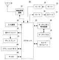
- FIG. 2 is an illustrative view showing an electrical configuration of the mobile phone shown in FIG.
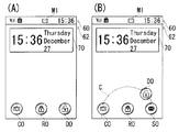
- FIG. 3 is an illustrative view showing one example of a lock screen displayed on the display shown in FIG.
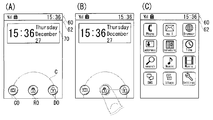
- FIG. 4 is an illustrative view showing an example of an operation when releasing the lock state set in the mobile phone shown in FIG. 1, and
- FIG. 4A shows a circle displayed further on the lock screen shown in FIG. 4B shows an example of the direction of the touch operation performed on the lock object shown in FIG. 3, and
- FIG. 4C shows an example of the standby screen.
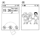
- FIG. 5 is an illustrative view showing another example of the operation when the lock state set in the mobile phone shown in FIG. 1 is released.
- FIG. 5 (A) shows the lock object shown in FIG. 4 (A).
- FIG. 5C illustrates an example of a state in which the camera function is executed after the lock state is released.
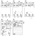
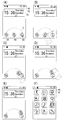
- 6 is an illustrative view showing another example of the operation when releasing the lock state set in the mobile phone shown in FIG. 1, and FIG. 6 (A) is a lock screen when a new mail is received.
- 6B shows an example of a state in which the circumference and the mail object are further displayed on the lock screen shown in FIG. 6A
- FIG. 6C shows the state shown in FIG. FIG.
- FIG. 6D shows an example of the direction of the touch operation performed on the lock object.
- FIG. 6D shows an example of a state in which a detailed pop-up is further displayed on the lock screen shown in FIG. Shows an example of a state in which the mail function is executed after the lock state is released.
- FIG. 7 is an illustrative view showing one example of a configuration of a notification information table stored in the RAM shown in FIG.
- FIG. 8 is an illustrative view showing one example of a state in which a circle, a mail object, an alarm object, and a number icon are further displayed on the lock screen shown in FIG.
- FIG. 9 is an illustrative view showing an example of screen transition until the specific notification icon is displayed on the lock screen shown in FIG. 6 (A), and FIG.
- FIG. 9 (A) is a lock screen when new mail is received.
- FIG. 9B shows an example in which the circumference and the specific notification object are further displayed on the lock screen shown in FIG.
- FIG. 10 is an illustrative view showing one example of a configuration of a specific mail address table stored in the RAM shown in FIG.
- FIG. 11 is an illustrative view showing one example of a configuration of a display position table stored in the RAM shown in FIG.
- FIG. 12 is an illustrative view showing one example of an operation procedure when the display position of the object displayed on the lock screen shown in FIG. 6 (B) is changed
- FIG. 12 (A) is a lock shown in FIG. 6 (A).
- FIG. 10 is an illustrative view showing one example of a configuration of a specific mail address table stored in the RAM shown in FIG.
- FIG. 11 is an illustrative view showing one example of a configuration of a display position table stored in the RAM shown in FIG.
- FIG. 12 is an
- FIG. 12B shows an example of a state in which the circumference and the mail object are further displayed on the screen
- FIG. 12B shows an example of a touch operation performed on the mail object
- FIG. 12C shows the display position of the mail object.
- An example of the display after a change is shown.
- FIG. 13 is an illustrative view showing another example of the operation procedure when changing the display position of the object displayed on the lock screen shown in FIG. 6B
- FIG. FIG. 13B shows another example of the display after the display position of the mail object is changed.
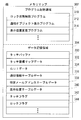
- FIG. 14 is an illustrative view showing one example of a memory map of the RAM shown in FIG.
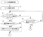
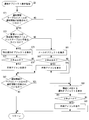
- FIG. 15 is a flowchart showing an example of a part of the lock state releasing process of the processor shown in FIG.
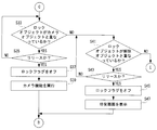
- FIG. 16 is an example of another part of the processor lock state releasing process shown in FIG. 2, and is a flowchart subsequent to FIG.
- FIG. 17 is an example of another part of the processor lock state releasing process shown in FIG. 2, and is a flowchart subsequent to FIG. 18 is an example of still another part of the processor lock state releasing process shown in FIG. 2, and is a flowchart subsequent to FIG.
- FIG. 19 is a flowchart showing an example of notification object display processing of the processor shown in FIG.
- FIG. 20 is a flowchart showing an example of the display position changing process of the processor shown in FIG.
- FIG. 21 is an illustrative view showing still another example of the operation when releasing the lock state set in the mobile phone shown in FIG. 1, and FIG.
- FIG. 21 (A) shows a circle on the lock screen shown in FIG. Furthermore, an example of the displayed state is shown, FIG. 21B shows another example of the direction of the touch operation performed on the lock object shown in FIG. 3, and FIG. 21C is shown in FIG.
- FIG. 21D shows an example of a state where a touch operation is being performed in the direction shown in FIG. 21D.
- FIG. 21D shows an example of a state where the touch operation is performed in the direction shown in FIG. Indicates a state where the touch operation is completed, and
- FIG. 21F illustrates an example of a standby screen.
- FIG. 22 is an illustrative view showing another example of the operation when releasing the lock state set in the mobile phone shown in FIG. 1, and FIG.
- FIG. 22 (A) further shows the circumference on the lock screen shown in FIG. An example of the displayed state is shown
- FIG. 22B shows another example of the direction of the touch operation performed on the lock object shown in FIG. 3
- FIG. 22C shows the example of FIG.
- FIG. 22D illustrates an example of a state in which a touch operation is performed in the direction
- FIG. 22D illustrates an example of a state in which the touch operation is performed in the direction illustrated in FIG. 22B
- FIG. An example of a standby screen is shown.
- a mobile phone 10 is a smartphone as an example, and includes a vertically long flat rectangular housing 12.
- the present invention can be applied to any portable terminal such as a tablet terminal or a PDA.
- a display 14 such as a liquid crystal or an organic EL that functions as a display unit is provided.
- a touch panel 16 is provided on the display 14. Therefore, in the cellular phone 10 of this embodiment, most of the input operations except those by hard key operations described later are performed through the touch panel 16.
- a speaker 18 is built in the main surface side of one end of the housing 12 in the vertical direction, and a microphone 20 is built in the main surface side of the other end in the vertical direction.
- a call key 22a, an end key 22b, and a menu key 22c are provided on one main surface of the housing 12 as hard keys that constitute input operation means together with the touch panel 16.
- a lens opening 24 that communicates with the camera module 50 is provided at one longitudinal end of the other surface (back surface) of the housing 12.
- the user can input a telephone number by touching the dial keys displayed on the display 14 with the touch panel 16, and can start a voice call by operating the call key 22a. If the end call key 22b is operated, the voice call can be ended. Note that the power supply of the mobile phone 10 can be turned on / off by long-pressing the end call key 22b.
- a menu screen is displayed on the display 14, and the menu is displayed by touching the touch panel 16 with respect to the soft keys and menu icons displayed on the display 14 in that state. Select and confirm the selection.
- the camera module 50 is activated and a preview image (through image) corresponding to the object scene is displayed on the display 14. Then, the user can shoot the subject by performing a shooting operation with the other surface provided with the lens opening 24 directed toward the subject.
- the mobile phone 10 of the embodiment shown in FIG. 1 includes a processor 30 called a computer or a CPU.
- a wireless communication circuit 32, an A / D converter 36, a D / A converter 38, an input device 40, a display driver 42, a flash memory 44, a RAM 46, a touch panel control circuit 48, a camera module 50, and the like are connected to the processor 30.
- the processor 30 The wireless communication circuit 32, an A / D converter 36, a D / A converter 38, an input device 40, a display driver 42, a flash memory 44, a RAM 46, a touch panel control circuit 48, a camera module 50, and the like are connected to the processor 30.
- the processor 30 called a computer or a CPU.
- the processor 30 manages the overall control of the mobile phone 10.
- the RAM 46 functioning as a storage unit, all or a part of a program preset in the flash memory 44 is expanded when used, and the processor 30 operates according to the program on the RAM 46.
- the RAM 46 is further used as a working area or a buffer area for the processor 30.
- the input device 40 includes the touch panel 16 and the hard keys 22a, 22b and 22c shown in FIG. Therefore, an operation receiving unit that receives a touch operation from the user on the touch panel 16 and a key operation from the user on the hard key 22 is configured. Information on the hard key operated by the user (key data) is input to the processor 30.
- the wireless communication circuit 32 is a circuit for transmitting and receiving radio waves for voice calls and mails through the antenna 34.
- the wireless communication circuit 32 is a circuit for performing wireless communication by the CDMA method. For example, when the user operates the input device 40 to instruct a telephone call (calling), the wireless communication circuit 32 performs a telephone call processing under the instruction of the processor 30 and sends a telephone call signal via the antenna 34. Output. The telephone call signal is transmitted to the other party's telephone through the base station and the communication network. When an incoming call process is performed at the other party's telephone, a communicable state is established, and the processor 30 executes a call process.
- the microphone 20 shown in FIG. 1 is connected to the A / D converter 36, and an audio signal from the microphone 20 is input to the processor 30 as digital audio data through the A / D converter 36.
- the speaker 18 is connected to the D / A converter 38.
- the D / A converter 38 converts digital audio data into an audio signal and supplies the audio signal to the speaker 18 through an amplifier. Therefore, sound based on the sound data is output from the speaker 18.
- the display driver 42 controls display on the display 14 connected to the display driver 42 under the instruction of the processor 30.
- the display driver 42 includes a video memory that temporarily stores image data to be displayed.
- the display 14 is provided with a backlight using, for example, an LED as a light source, and the display driver 42 controls the brightness of the backlight and lighting / extinguishing in accordance with instructions from the processor 30.
- the touch panel 16 shown in FIG. 1 is connected to the touch panel control circuit 48.
- the touch panel control circuit 48 applies necessary voltage and the like to the touch panel 16 and also displays a touch start signal indicating the start of touch by the user on the touch panel 16, an end signal indicating the end of touch by the user, and a touch position touched by the user.
- the indicated coordinate data is input to the processor 30. Therefore, the processor 30 can determine which icon or key displayed on the display 14 is touched by the user based on the coordinate data.
- the touch panel 16 is a capacitive touch panel that detects a change in capacitance generated between the surface and an object such as a finger approaching the surface.
- the touch panel 16 detects that one or more fingers touched the touch panel 16, for example. Therefore, the touch panel 16 is also called a pointing device.
- the touch panel control circuit 48 functions as a detection unit, detects a touch operation within the touch effective range of the touch panel 16, and outputs coordinate data indicating the position of the touch operation to the processor 30. That is, the user inputs an operation position, an operation direction, and the like to the mobile phone 10 by performing a touch operation on the surface of the touch panel 16.
- the touch operation of this embodiment includes a tap operation, a long tap operation, a flick operation, a slide operation, and the like.
- the tap operation is an operation of releasing (releasing) the finger from the surface of the touch panel 16 in a short time after the finger touches (touches) the surface of the touch panel 16.
- the long tap operation is an operation in which the finger is kept in contact with the surface of the touch panel 16 for a predetermined time or longer and then the finger is released from the surface of the touch panel 16.
- the flick operation is an operation of bringing a finger into contact with the surface of the touch panel 16 and flipping the finger in an arbitrary direction at a predetermined speed or higher.
- the slide operation is an operation of moving the finger in any direction while keeping the finger in contact with the surface of the touch panel 16 and then releasing the finger from the surface of the touch panel 16.
- the above slide operation includes a so-called drag operation in which a finger touches an object displayed on the surface of the display 14 and moves the object.
- an operation of releasing a finger from the surface of the touch panel 16 after a drag operation is referred to as a drop operation.
- the touch operation, the long tap operation, the flick operation, the slide operation, the drag operation, and the drop operation may be described by omitting “operation”.
- the objects of this embodiment include icons for executing functions, shortcut icons, files, folders, and the like.
- a resistive film method an ultrasonic method, an infrared method, an electromagnetic induction method, or the like may be employed instead of the capacitance method described above.
- the touch operation is not limited to the user's finger, and may be performed with a stylus pen or the like.
- the camera module 50 includes a control circuit, a lens, an image sensor, and the like.
- the processor 30 activates the control circuit and the image sensor.
- image data based on the signal output from the image sensor is input to the processor 30, a preview image corresponding to the subject is displayed on the display 14.
- the mobile phone 10 of this embodiment can execute a mail function and an alarm function in addition to the telephone function.
- the mobile phone 10 can set a lock state that restricts execution of a predetermined process based on the touch operation in order to prevent an erroneous operation due to an input unintended by the user on the touch panel 16.
- a lock state that restricts execution of a predetermined process based on the touch operation in order to prevent an erroneous operation due to an input unintended by the user on the touch panel 16.
- the display 14 and the touch panel 16 are turned off and the locked state is set.
- the menu key 22c or the like is operated in this state, the display 14 and the touch panel 16 are turned on, the lock screen shown in FIG. 3 is displayed, and the unlocking operation can be accepted.
- the display 14 is automatically turned off and the locked state is set.
- the power of the mobile phone 10 can be suppressed because the display 14 and the touch panel 16 are turned off until the lock screen is displayed.
- the touch operation may be invalidated by not processing the touch operation input by the processor 30 without turning off the power of the touch panel 16.
- the display range of display 14 displaying the lock screen includes a status display area 60 and a function display area 62.
- a status display area 60 an icon (pict) indicating the radio wave reception status by the antenna 34, an icon indicating the remaining battery capacity of the secondary battery, and the date and time are displayed.
- the function display area 62 the current date and time 70 are displayed, and a lock object RO, a release object DO, and a camera object CO are displayed on the lower side.
- the lock state is released.
- a standby screen is displayed instead of the lock screen as shown in FIG. That is, the user can release the lock state by dragging the lock object RO and dropping it on the release object DO.
- the lock object RO and the release object DO are displayed on the lower side of the display 14 as shown in FIG. The state can be released.
- the user can easily perform the unlocking operation with one hand.
- the lock object RO when the lock object RO is dropped onto the release object DO, the lock object RO may overlap with a part of the release object DO, or may overlap with the whole. That is, the locked state is released regardless of which state is dropped.
- a mail icon MI is displayed in the status display area 60.
- the mail object Oa is displayed on the circumference C in addition to the release object DO and the camera object CO as shown in FIG.
- a detailed pop-up P is displayed.
- This detailed pop-up P includes the sender (“**”) and the title of the mail (“Notification”) as information on the new mail. That is, the user can check a part of the contents of the unread received mail without releasing the lock state. Therefore, the user can determine whether to execute the function corresponding to the notification object. For example, when the user confirms the detail pop-up P and determines that the mail is not important, the user may end the drag operation without releasing the lock state. In another embodiment, the text of an unread received mail may be displayed on the detail pop-up P.
- the lock state is released and the mail function is executed.
- the mail function is executed, an unread new mail is displayed in the function display area 62. That is, the user can check the unread received mail while releasing the lock state with a few operation procedures.
- a received mail list including unread received mail may be displayed in the function display area 62. In this case, the user can check other received mails together with unread received mails.
- the mail object Oa is displayed when mail notification information is recorded in the notification information table.
- FIG. 7 is an illustrative view showing one example of a configuration of a notification information table.
- the notification information table includes a function column, a display information column, and a count column.
- an event occurs, a new row is added, and an event occurring in the added row is displayed. Notification information is recorded.
- the content recorded in the display information is updated to the content of the event that occurred last. That is, in the new mail notification information shown in FIG. 7, the content recorded in the display information corresponds to the last received new mail.
- notification object O the notification information is recorded when a missed call occurs or when voice is recorded by the answering machine function.
- notification object O the objects displayed based on the notification information may be collectively referred to as “notification object O”.
- notification information is recorded as shown in FIG. 7, if the lock object RO is touched, the mail object Oa and the alarm object Ob included in the notification object O are displayed. Is displayed on the circumference C.
- the number icon NI is assigned to the mail object Oa.
- the number icon NI indicates the number of events generated by the function corresponding to the notification object O (here, the mail object Oa). Therefore, the number icon NI of FIG. 8 includes a character string “3” indicating that three new mails have been received. Thereby, the user can grasp
- the lock object RO when the lock object RO is dropped on the mail object Oa to which the number icon NI is assigned, the newly received new mail is displayed in the function display area 62.
- the alarm time and the notified content are displayed in the function display area 62. In this case, the user can grasp the contents of the notified alarm.
- the display mode of the notification object O is changed in accordance with the function corresponding to the notification information, the user can intuitively grasp the notification information.
- the notification icon O is displayed at a predetermined distance from the lock object RO, so that the lock state is not released due to an erroneous operation.
- the specific notification object SO when a mail is received from a specific person (sender), the specific notification object SO is displayed instead of the notification object O.
- the specific notification object SO is displayed at a position where it can be easily dropped.
- FIG. 9A shows an example of a position where the lock object RO can be easily dropped onto the release object DO.
- the lower side of the screen on which the touch panel 16 can be operated with the finger of the hand opposite to the held hand is defined as an easy-to-drop position. is doing.
- the specific object SO is displayed at the position where the release object DO was displayed. Further, the release object DO is displayed on the upper side of the circumference C with respect to the original display position.
- the user can recognize that there is a new mail from a specific caller without releasing the lock state. That is, in the present embodiment, when important notification information is recorded, the specific notification object SO having a different display form from the normal notification object O is displayed, so that the user stores important notification information. I can know that. In this embodiment, when a new mail is received from a specific sender, the display position of the object is changed so that the user can more easily confirm the contents.
- the mail address of a specific sender is registered in the specific mail address table.
- the specific mail address is registered in advance by the business operator, but the user can arbitrarily add the specific mail address.
- the default display position (display coordinates) of the object displayed on the lock screen is recorded in the display position table.
- the display position table includes an object column and a display position column, and the display position is recorded in association with the name of the object for each row.
- (X 1 , Y 1 ) is recorded in association with the lock object RO as the display position.
- the display position table also records display positions of the release object DO, the camera object CO, the mail object Oa, and the like.
- the notification object O when the notification object O is displayed, if the arbitrary notification object O is dragged and dropped at an arbitrary position on the circumference C, the default display position of the dragged notification object O is changed. The That is, the user can change the position where the notification object O is displayed to a position where the user can easily operate.
- the default display position of the target notification object O is changed after changing the display position of the other object to another display position. Change to the display position where other objects were displayed.
- the display position of the release object DO is changed to the upper side. Then, the display position of the mail object Oa is changed to the position where the release object DO was originally displayed.
- the present embodiment by displaying the notification object O, it is possible to easily execute the function that is highly likely to be executed by the user together with the release of the lock state. Thereby, the convenience of the mobile phone 10 in which the locked state is set is improved.
- program storage area 302 and data storage area 304 are formed in RAM 46 shown in FIG. 2.
- the program storage area 302 is an area for reading and storing (developing) part or all of the program data set in advance in the flash memory 44 (FIG. 2).
- the program storage area 302 stores a lock state release program 310, a notification object display program 312 and a display position change program 314.
- the lock state release program 310 is a program for releasing the lock state or executing a function together with the release of the lock state.
- the notification object display program 312 is a program executed when displaying the notification object O.
- the display position change program 314 is a program executed when the display position of the notification object O or the like is arbitrarily changed (edited).
- program storage area 302 also includes programs for executing a telephone function, an answering machine function, a mail function, an alarm function, and the like.
- a touch buffer 330 is provided in the data storage area 304 of the RAM 46, and touch coordinate map data 332, GUI data 334, notification information table data 336, specific mail address table data 338, display position table data 340, and the like.
- the data storage area 304 is also provided with a touch flag 342 and a lock flag 344.
- touch coordinate data output from the touch panel control circuit 48 is stored.
- the touch coordinate map data 332 is data for associating the touch coordinates in the touch operation with the display coordinates on the display 14. That is, the result of the touch operation performed on the touch panel 16 is reflected on the display 14 based on the touch coordinate map data 332.
- the GUI data 334 is data for displaying GUIs such as the lock object RO, the release object DO, the camera object CO, the notification object O, the mail icon MI, and the number icon NI.
- the notification information table data 336 is data in which notification information is recorded as shown in FIG.
- the specific mail address table data 338 is data in which a specific mail address registered by a user or the like is recorded.
- the display position table data 340 is data in which the display position of each object displayed on the lock screen is recorded.
- the touch flag 342 is a flag for determining whether or not the touch panel 16 is touched.
- the touch flag 342 is composed of a 1-bit register. When the touch flag 342 is turned on (established), a data value “1” is set in the register. On the other hand, when the touch flag 342 is turned off (not established), a data value “0” is set in the register. Touch flag 342 is switched on / off based on a signal output from touch panel control circuit 48.
- the lock flag 344 is a flag for indicating whether or not the lock state is set. For example, the lock flag 344 is turned on in accordance with processing for turning off the power of the display 14 and the touch panel 16. Further, the lock flag 344 is turned off in accordance with the processing of the lock state release program 310 described above. Since the configuration of the lock flag 344 is substantially the same as that of the touch flag 342, detailed description of the configuration is omitted.
- the data storage area 304 stores image data displayed in a standby state, character string data, and the like, and is provided with counters and flags necessary for the operation of the mobile phone 10.
- the processor 30 performs a lock state release process shown in FIGS. 15 to 18 and a notification object display shown in FIG. 19 under the control of a Linux (registered trademark) -based OS such as Android (registered trademark) and REX, and other OSs.
- a Linux (registered trademark) -based OS such as Android (registered trademark) and REX, and other OSs.
- a plurality of tasks including the process and the display position change process shown in FIG. 20 are processed in parallel.
- the lock state release process is started when the power of the display 14 is turned on in a state where the lock state is set (the lock flag 344 is on).
- step S1 the processor 30 acquires date / time information from the RTC, reads out the image data of the lock object RO included in the GUI data 334, and locks the function display area 62 of the display 14 as shown in FIG. Display the screen.
- step S3 the processor 30 determines whether or not a touch operation has been performed on the lock object RO. Specifically, the processor 30 includes coordinates indicating the current touch position stored in the touch buffer 330 within a predetermined range of the display position (display coordinates) of the lock object RO in the display position table data 340. Judgment is made.
- the processor 30 determines whether or not the power of the display 14 is turned off in a step S5. For example, when the end call key 22b is operated or the display on the display 14 does not change for a certain period of time, the display 14 is turned off. Therefore, the processor 30 determines whether the power of the display 14 is turned off due to these factors in step S5. If “YES” in the step S5, that is, if the power of the display 14 is turned off, the processor 30 ends the lock state releasing process.
- step S5 determines whether or not there is notification information in a step S7. That is, it is determined whether notification information is recorded in the notification information table data 336. If “YES” in the step S7, that is, if the notification information is recorded, the processor 30 executes a notification object display process in a step S9, and proceeds to the process in the step S11 in FIG. Since the notification object display process will be described later, a detailed description thereof is omitted here.
- the processor 30 that executes the process of step S9 functions as a display processing unit.
- step S7 that is, if the notification information is not recorded, the processor 30 proceeds to the process of the step S11.
- step S11 of FIG. 16 the processor 30 determines whether or not the lock object RO is being dragged. That is, it is determined whether or not an operation of sliding the lock object RO as it is is performed. If “NO” in the step S11, that is, if the drag operation is not performed on the lock object RO, the processor 30 determines whether or not the notification object O is dragged in a step S13. That is, after touching the notification object O, it is determined whether an operation of sliding as it is performed.
- step S13 If “NO” in the step S13, that is, if the notification object O is not dragged, the processor 30 proceeds to the process of the step S17. On the other hand, if “YES” in the step S13, that is, if the notification object O is dragged, the processor 30 executes a display position changing process in a step S15. Since this display position changing process will be described later, a detailed description thereof is omitted here.
- step S17 the processor 30 determines whether the display 14 is powered off as in step S5. If “YES” in the step S17, that is, if the power of the display 14 is turned off, the processor 30 ends the lock state releasing process. On the other hand, if “NO” in the step S17, that is, if the power of the display 14 is not turned off, the processor 30 returns to the process of the step S11.
- step S11 determines whether or not the lock object RO overlaps with the notification object O in a step S19. For example, as shown in FIG. 6D, it is determined whether a part of the lock object RO overlaps with a part of the mail object Oa (notification object O). If “NO” in the step S19, that is, if the lock object RO does not overlap the notification object O, the processor 30 proceeds to the process of step S33 in FIG.
- step S19 If “YES” in the step S19, that is, if the lock object RO overlaps with the notification object O, the processor 30 displays the detailed pop-up P in a step S21. For example, as shown in FIG. 6D, a detailed popup P in which a part of the notification information corresponding to the notification object O is described is displayed. Note that the processor 30 that executes the process of step S21 functions as a notification information display unit.
- step S23 the processor 30 determines whether or not it has been released. That is, it is determined whether the lock object RO has been dropped on the notification object O.
- the processor 30 that executes the process of step S23 functions as a determination unit.
- step S23 If “YES” in the step S23, that is, if the lock object RO is released in a state of being overlapped with the notification object O, the processor 30 turns off the lock flag 344 in a step S25. That is, the locked state is released. Subsequently, the processor 30 executes a function corresponding to the notification object O in step S27. For example, when a drop operation is performed on the mail object Oa, the mail function is executed and a new mail is displayed in the function display area 62 as shown in FIG. At this time, the notification information corresponding to the mail object Oa is deleted from the notification information table data 336. Then, when the process of step S27 ends, the processor 30 ends the lock state release process. In addition, the processor 30 which performs the process of step S25 and step S27 functions as an execution part.
- step S23 determines whether or not the notification object O is separated from the lock object RO in a step S29. That is, it is determined whether or not the lock object RO has not overlapped with the notification object O. If “NO” in the step S29, that is, if the touch position does not change while the lock object RO is overlapped with the notification object O, the processor 30 returns to the process of step S23.
- step S29 that is, if the lock object RO leaves the notification object O, the processor 30 deletes the detailed pop-up P in a step S31. For example, the detailed pop-up P displayed as shown in FIG. 6D is deleted. Then, when the process of step S31 ends, the processor 30 proceeds to the process of step S33 in FIG.
- step S33 the processor 30 determines whether or not the lock object RO overlaps the camera object CO. That is, it is determined whether a part of the lock object RO overlaps with a part of the camera object CO.
- step S33 determines whether or not it has been released in a step S35. That is, it is determined whether the lock object RO has been dropped on the camera object CO. If “NO” in the step S35, that is, if the camera object CO is not dropped, the processor 30 returns to the process of the step S33.
- step S35 determines whether or not a drop operation is performed on the camera object CO. That is, as shown in FIG. 5B, since the locked state is released and the camera function is executed, a through image is displayed on the display 14.
- the processor 30 determines whether or not the lock object RO overlaps the release object DO in a step S41. That is, it is determined whether a part of the lock object RO overlaps with a part of the release object DO. If “YES” in the step S41, that is, if the lock object RO overlaps with the release object DO, the processor 30 determines whether or not it has been released in a step S43. That is, it is determined whether the lock object RO is dropped on the release object DO. If “NO” in the step S43, that is, if the drop operation is not performed on the release object DO, the processor 30 returns to the process of the step S41.
- step S43 that is, if a drop operation is performed on the release object DO
- the processor 30 turns off the lock flag 344 in a step S45 and displays a standby screen in a step S47. . That is, as shown in FIG. 4C, the locked state is released and the standby screen is displayed on the display 14. Then, when the process of step S47 ends, the processor 30 ends the lock state release process.
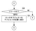
- step S41 determines whether or not it has been released in step S49 of FIG. That is, it is determined whether or not the lock object RO has been released without overlapping with other objects. If “NO” in the step S49, that is, if not released, the process returns to the process of the step S19 in FIG. On the other hand, if “YES” in the step S49, that is, if the lock object RO is released in a state where it does not overlap with other objects, the processor 30 displays the lock object RO in a default position in a step S51, The process returns to S11. That is, the processor 30 restores the display position of the lock object RO as shown in FIG.
- FIG. 19 is a flowchart of the notification object display process.
- the processor 30 determines in step S71 whether or not mail notification information is recorded in the notification information table. For example, the processor 30 determines whether there is a row in which “mail” is recorded in the function column as in the notification information table illustrated in FIG. 7. If “NO” in the step S71, that is, if the mail notification information is not recorded, the processor 30 proceeds to the process of the step S89.
- the processor 30 determines whether or not the sender of the new mail is registered in the specific mail address table in a step S73. That is, it is determined whether a new mail has been received from a sender whose mail address is registered in the specific mail address table. If “YES” in the step S73, that is, if the address of the sender of the new mail is recorded in the specific mail address table, the processor 30 displays the specific notification object SO in a step S75. For example, as shown in FIG. 9B, the specific notification object SO is displayed on the circumference C. If “YES” is determined in the step S73, the contents of the display position table data 340 are changed so that the specific notification object SO is displayed at the default display position of the release object DO.
- step S77 the processor 30 determines whether or not there are two or more. That is, it is determined whether or not the number of cases is “2” or more in the mail notification information. If “NO” in the step S77, that is, if the number of cases is “1”, the processor 30 proceeds to a process of step S87. If “YES” in the step S77, for example, if the number of cases is “3”, the processor 30 displays the number of icons NI in a step S79, and proceeds to the process of the step S87. For example, the number icon NI shown in FIG. 8 is given to the specific notification object SO.
- step S73 determines whether or not there are two or more. That is, it is determined whether the number of newly received mails is 2 or more while the lock state is set. If “NO” in the step S83, for example, if the number of newly received mails is one, the processor 30 proceeds to the process of the step S87.
- the processor 30 displays the number icon NI in a step S85, and proceeds to the process of the step S87. For example, as shown in FIG. 8, the number icon NI is given to the mail object Oa.
- step S87 the processor 30 determines whether or not notification information other than mail is recorded in the notification information table. For example, it is determined whether notification information such as an alarm is recorded. If “NO” in the step S87, that is, if notification information other than mail is not recorded, the processor 30 ends the notification object display process and returns to the lock state release process.
- step S87 if “YES” in the step S87, if alarm notification information is recorded as in the notification information table shown in FIG. 7, for example, the processor 30 selects the notification object O corresponding to the function in a step S89. indicate. For example, if alarm notification information is recorded, an alarm object Ob is displayed as shown in FIG. Subsequently, in step S91, the processor 30 determines whether or not there are two or more. That is, it is determined whether the number of records of the same type of notification information is two or more. If “NO” in the step S91, if the number of records of the same type of notification information is one, the processor 30 ends the notification object display process and returns to the lock state release process.
- the processor 30 displays the number icon NI in the step S93 and performs the notification object display process. finish.
- notification information of a plurality of functions is recorded, a plurality of notification objects O corresponding to each notification information are displayed in the process of step S89.
- processor 30 that executes the processes of steps S79, S85, and S93 functions as a display mode changing unit.
- FIG. 20 is a flowchart of the display position change process.
- the processor 30 determines whether or not the release has been performed in step S111. That is, it is determined whether the touch operation on any notification object O has been completed. If “NO” in the step S111, that is, if not released, the processor 30 repeats the process of the step S111. If “YES” in the step S111, that is, if released, the processor 30 determines whether or not the end position is on the circumference C in a step S113. That is, it is determined that the notification object O has been dropped on the circumference C. If “NO” in the step S113, that is, if the notification object O is not dropped on the circumference C, the processor 30 ends the display position changing process and returns to the lock state releasing process.
- the processor 30 determines whether or not there is another object at the end position in a step S115. For example, it is determined whether the notification object O has been dropped. If “NO” in the step S115, for example, as shown in FIG. 12B, when the other notification object O is not displayed and is released on the circumference C, the processor 30 proceeds to the step S119. Proceed to processing.
- step S115 when the mail object Oa is dropped at the position where the release object DO is displayed, the processor 30 in a step S117, Change the display position of other objects. For example, as shown in FIG. 13B, the display position of the release object DO is changed to the upper side. At this time, the display position of the release object DO in the display position table is also changed.
- step S119 the processor 30 changes the display position of the dropped object.
- the dropped position end position
- the display position of the mail object Oa in the display position table is also changed.
- the processor 30 that executes the process of step S119 functions as a display position changing unit.
- the locked state is released even if the lock object RO overlaps part or all of the release object DO by sliding.
- the change in the display position of the lock object RO stops when it overlaps part or all of the release object DO. That is, when the lock object RO overlaps part or all of the release object DO due to the slide, the display position of the lock object RO does not follow the touch position.
- the locked state when the touch position exceeds the circumference C, the locked state may be released. More specifically, as described above, after the lock object RO is slid and overlaps a part or all of the release object DO, when the touch position exceeds the circumference C, the release object DO is placed on the circumference C. Stop at. However, the locked state is released here even if it is not released. In this way, the user can release the locked state without performing more operations than necessary.
- the lock state is also released when the lock object RO is flicked and overlaps a part or all of the release object DO. If the lock object RO does not overlap with other objects due to flicking, the lock state is not released and the lock object RO returns to the original location.
- the slide and flick for releasing the lock state may be performed not only on the release object DO but also on the camera object CO and the notification object O. If these operations are performed, the lock state is released.
- a security screen that prompts for a password may be displayed when the unlocking operation is performed. For example, when a release operation is performed on the lock object RO, a security screen is displayed on the display 14. When a correct password is entered on the security screen, a standby screen shown in FIG. At this time, if an incorrect password is entered, the password must be entered again.
- the default display position of an object may be changed when a touch operation is performed on an arbitrary object for a predetermined time or longer.
- the incoming call response screen includes an incoming call response object for releasing the lock state and responding to an incoming call. Then, when the lock object RO is dropped with respect to the incoming call response object, a call is started.
- a function corresponding to SNS such as Facebook (registered trademark) or Mixi (registered trademark) may record the notification information.
- SNS Social Network Service
- Facebook registered trademark
- Mixi registered trademark
- the program used in this embodiment may be stored in the HDD of the data distribution server and distributed to the mobile phone 10 via the network.
- a storage medium may be sold or distributed in a state where a plurality of programs are stored in a storage medium such as an optical disk such as a CD, DVD, or BD (Blue-Ray Disk), a USB memory, or a memory card.
- the present embodiment has a display unit and a touch panel provided on the surface of the display unit, can set a lock state that restricts execution of predetermined processing based on a touch operation, and is locked when the lock state is set
- a lock object for releasing the notification is displayed on the display unit, and is a storage unit for storing notification information, and when the lock object is displayed, a notification object corresponding to the notification information is displayed on the display unit.
- a display processing unit that performs determination, a determination unit that determines whether a predetermined touch operation for moving and releasing the lock object onto at least a part of the display area of the notification object has been performed, and a determination unit that determines that the predetermined touch operation has been performed.
- the mobile terminal (10: reference numeral exemplifying a corresponding part in the embodiment; hereinafter the same) is, for example, a mobile phone, and a touch panel (16) is provided on the surface of the display unit (14). It has been. Since the mobile terminal performs the main operation on the touch panel, it is possible to set a lock state that restricts execution of a predetermined process based on the touch operation in order to prevent an erroneous operation. Further, when the display unit is turned on while the lock state is set, a lock object (RO) for releasing the lock state is displayed on the display unit. For example, when an event of an arbitrary function occurs, the storage unit (46) stores notification information.
- the storage unit (46) stores notification information.
- the display processing unit (30, S9) displays a notification object (Oa, Ob, SO) corresponding to the notification information around the lock object.
- the determination unit (30, S23) determines whether a predetermined touch operation for moving and releasing the lock object to at least a part of the display area of the notification object has been performed.
- the execution unit (30, S25, S27) releases the lock state and executes functions (email function, alarm function, etc.) corresponding to the notification object.
- the display of the lock object and the notification object disappears and the GUI of the executed function is displayed on the display unit.
- the present embodiment by displaying the notification object, it is possible to easily execute a function that is highly likely to be executed by the user together with the release of the locked state. Thereby, the convenience of the portable terminal set with the locked state is improved.
- Another embodiment further includes a notification information display unit that displays at least a part of the notification information when the lock object is moved onto at least a part of the display area of the notification object.
- the notification information display unit (30, S21) for example, when a lock object overlaps at least a part of the notification object, a part of the notification information (for example, the sender of the mail or the content of the alarm). Is displayed using a pop-up (P) or the like.
- the user can determine whether to execute the function corresponding to the notification object.
- Other embodiments further include a display mode changing unit that changes the display mode of the notification object corresponding to the notification information when a plurality of notification information of the same type is recorded.
- the display mode changing unit (30, S79, S85, S93) gives an icon (NI) indicating the number of recorded cases to the notification object.
- NI icon
- the user can more accurately grasp the recorded notification information.
- Still another embodiment further includes a display position changing unit that changes the display position of the notification object when an operation for changing the display position of the notification object is performed.
- the display position changing unit (30, S119) slides with the notification object touched and is released at an arbitrary position when the notification object is displayed, for example.
- the display position where the notification object is displayed by default is changed to the released position.
- the user can change the position where the notification object is displayed to a position where the user can easily operate.
- the notification object is displayed in a different display mode for each function corresponding to the notification information.
- the notification object (Oa) corresponding to the notification information of the mail function and the notification object (Ob) corresponding to the notification information of the alarm function are displayed in different display modes.
- the user can intuitively grasp the notification information by changing the display mode of the notification object in accordance with the function corresponding to the notification information.
- the notification information includes information on the received mail, and when the determination unit determines that a predetermined touch operation is performed on the notification object corresponding to the information on the received mail, the execution unit releases the locked state. And execute the mail function.
- the notification information includes received mail information (sender, title, etc.).
- the execution unit releases the lock state and executes the mail function.
- the recording unit records notification information when a mail is received, and information on the received mail is displayed on the display unit when the mail function is executed by the execution unit.
- the recording unit when the mail is received, the recording unit records notification information including information on the received mail. Further, when the mail function is executed by a predetermined touch operation, information related to the received mail is displayed on the display unit.
- the information related to the received mail includes the text of the received mail.
- the user can release the lock state and check unread received mails with a few operation procedures.
- the information related to the received mail includes a list of received mail.
- the user can check other received mails together with unread received mails.
- the display processing unit is specified in a display mode different from a notification object for notifying a received mail from a normal sender when the sender of the received mail is a predetermined sender.
- the notification object is displayed on the display unit.
- a specific notification object is displayed when mail is received from a specific caller in a locked state.
- the display processing unit displays the specific notification object at a different position from the notification object that notifies the received mail from the normal sender.
- the user can recognize that there is a new mail from a specific caller without releasing the lock state.
- the notification information includes alarm notification information.
- the user can grasp the contents of the alarm that has been notified.
- Still another embodiment includes a display unit (14), a touch panel (16) provided on the surface of the display unit, and a storage unit (46) for storing notification information, and executes predetermined processing based on a touch operation.
- an execution step (S25, S27) for releasing the lock state and executing a function (email function, alarm function) corresponding to the notification object is executed. This is a lock state release method.
- displaying the notification object makes it easy to execute a function that is highly likely to be executed by the user together with the release of the locked state. Thereby, the convenience of the portable terminal set with the locked state is improved.
Landscapes
- Engineering & Computer Science (AREA)
- Signal Processing (AREA)
- Computer Security & Cryptography (AREA)
- Computer Networks & Wireless Communication (AREA)
- Business, Economics & Management (AREA)
- General Business, Economics & Management (AREA)
- Human Computer Interaction (AREA)
- Telephone Function (AREA)
- User Interface Of Digital Computer (AREA)
Abstract
携帯電話機10は、ディスプレイ14およびタッチパネル16などを備え、タッチ操作に基づく所定の処理の実行を制限するロック状態を設定することが出来る。ロック状態が設定されているときにディスプレイ14がオンにされると、ロックオブジェクト(RO)などを含むロック画面が表示される。新着メールがあるときにロック画面が表示されると、ロック画面にはメールオブジェクト(Oa)がさらに表示される。このとき、ロックオブジェクトがドラッグされ、メールオブジェクトにドロップされると、ロック状態が解除されると共に、メール機能が実行される。このとき、ディスプレイ14には、新着メールが表示される。
Description
この発明は、携帯端末およびロック状態解除方法に関し、特にロック状態を設定することができる、携帯端末およびロック状態解除方法に関する。
ロック状態を設定することができる携帯端末の一例が特許文献1に開示されている。特許文献1の携帯端末装置では、ダブルタップする操作などのジェスチャが動作場面毎に登録される。そして、タッチパネルの動作が停止しているときに、タッチパネルに対して、動作場面に応じたジェスチャが行われると、タッチパネルが停止状態から正常動作に復帰する。
特開平11-203045号公報[G06F 3/033, G06F 3/00, H04Q 7/38, H04M 1/02, H04M 1/23]
特許文献1の携帯端末装置では、ユーザは、複数の動作場面を登録する場合、複数の動作場面と、それらに対応するジェスチャとを全て記憶しなければならない。そして、ユーザがタッチパネルを停止状態から正常動作に復帰させるときに、ジェスチャと動作場面との対応関係を忘れてしまうと、ユーザは携帯端末装置を思った通りに操作できなくなってしまう。
それゆえに、この発明の主たる目的は、新規な、携帯端末およびロック状態解除方法を提供することである。
この発明の他の目的は、ロック状態が設定されている携帯端末の利便性を向上させることが出来る、携帯端末およびロック状態解除方法を提供することである。
この発明の第1の局面は、表示部および表示部の表面上に設けられるタッチパネルを有し、タッチ操作に基づく所定の処理の実行を制限するロック状態を設定でき、ロック状態が設定されているときにロック状態を解除するためのロックオブジェクトが表示部に表示される、携帯端末であって、通知情報を記憶する記憶部、ロックオブジェクトが表示されているとき、通知情報に対応する通知オブジェクトを表示部に表示する表示処理部、通知オブジェクトの少なくとも一部の表示領域上にロックオブジェクトを移動させてリリースする所定タッチ操作が行われたかを判断する判断部、および判断部によって所定タッチ操作が行われたと判断されたとき、ロック状態を解除すると共に、当該通知オブジェクトに対応する機能を実行する実行部を備える、携帯端末である。
この発明の第2の局面は、表示部、表示部の表面上に設けられるタッチパネルおよび通知情報を記憶する記憶部を有し、タッチ操作に基づく所定の処理の実行を制限するロック状態を設定でき、ロック状態が設定されているときにロック状態を解除するためのロックオブジェクトが表示部に表示される、携帯端末におけるロック状態解除方法であって、携帯端末のプロセッサが、ロックオブジェクトが表示されているとき、通知情報に対応する通知オブジェクトを表示部に表示する表示処理ステップ、通知オブジェクトの少なくとも一部の表示領域上にロックオブジェクトを移動させてリリースする所定タッチ操作が行われたかを判断する判断ステップ、および判断ステップによって所定タッチ操作が行われたと判断されたとき、ロック状態を解除すると共に、当該通知オブジェクトに対応する機能を実行する実行ステップを実行する、ロック状態解除方法である。
この発明によれば、ロック状態が設定された携帯端末の利便性を向上させることが出来る。
この発明の上述の目的、その他の目的、特徴および利点は、図面を参照して行う以下の実施例の詳細な説明から一層明らかとなろう。
図1(A),(B)を参照して、この発明の一実施例の携帯電話機10は、一例としてスマートフォン(smart phone)であり、縦長の扁平矩形のハウジング12を含む。ただし、この発明は、タブレット端末、PDAなど任意の携帯端末に適用可能であることを予め指摘しておく。
ハウジング12の一方主面(表面)には、表示部として機能する、たとえば液晶や有機ELなどのディスプレイ14が設けられる。ディスプレイ14の上には、タッチパネル16が設けられる。したがって、この実施例の携帯電話機10では、後述のハードキーの操作によるものを除く大部分の入力操作は、このタッチパネル16を介して行われる。
ハウジング12の縦方向一端の主面側にスピーカ18が内蔵され、縦方向他端の主面側にマイク20が内蔵される。
ハウジング12の一方主面には、タッチパネル16と共に入力操作手段を構成するハードキーとして、この実施例では、通話キー22a、終話キー22bおよびメニューキー22cが設けられる。
また、ハウジング12の他面(裏面)の縦方向一端には、カメラモジュール50(図2参照)に通じるレンズ開口24が設けられている。
たとえば、ユーザは、ディスプレイ14に表示されたダイヤルキーに対して、タッチパネル16によってタッチ操作を行うことで電話番号を入力でき、通話キー22aを操作して音声通話を開始することができる。終話キー22bを操作すれば、音声通話を終了することができる。なお、この終話キー22bを長押しすることによって、携帯電話機10の電源をオン/オフすることができる。
また、メニューキー22cを操作すれば、ディスプレイ14にメニュー画面が表示され、その状態でディスプレイ14に表示されているソフトキーやメニューアイコンなどに対して、タッチパネル16によるタッチ操作を行うことによってメニューを選択し、その選択を確定させることができる。
さらに、詳細な説明は後述するが、カメラ機能が実行されると、カメラモジュール50が起動し、ディスプレイ14に被写界と対応するプレビュー画像(スルー画像)が表示される。そして、ユーザは、レンズ開口24が設けられている他面を被写体に向けて撮影操作を行うことで、被写体を撮影することが出来る。
図2を参照して、図1に示す実施例の携帯電話機10は、コンピュータまたはCPUと呼ばれるプロセッサ30などを含む。プロセッサ30には、無線通信回路32、A/D変換器36、D/A変換器38、入力装置40、表示ドライバ42、フラッシュメモリ44、RAM46、タッチパネル制御回路48およびカメラモジュール50などが接続される。
プロセッサ30は、携帯電話機10の全体制御を司る。記憶部として機能するRAM46には、フラッシュメモリ44に予め設定されているプログラムの全部または一部が使用に際して展開され、プロセッサ30はこのRAM46上のプログラムに従って動作する。なお、RAM46はさらに、プロセッサ30のワーキング領域ないしバッファ領域として用いられる。
入力装置40は、図1に示すタッチパネル16、ハードキー22a、22bおよび22cを含むものである。そのため、タッチパネル16に対するユーザからのタッチ操作や、ハードキー22に対するユーザからのキー操作を受け付ける操作受付部を構成する。ユーザが操作したハードキーの情報(キーデータ)はプロセッサ30に入力される。
無線通信回路32は、アンテナ34を通して、音声通話やメールなどのための電波を送受信するための回路である。実施例では、無線通信回路32は、CDMA方式での無線通信を行うための回路である。たとえば、ユーザが入力装置40を操作して電話発信(発呼)を指示すると、無線通信回路32は、プロセッサ30の指示の下、電話発信処理を実行し、アンテナ34を介して電話発信信号を出力する。電話発信信号は、基地局および通信網を経て相手の電話機に送信される。そして、相手の電話機において着信処理が行われると、通信可能状態が確立され、プロセッサ30は通話処理を実行する。
A/D変換器36には図1に示すマイク20が接続され、マイク20からの音声信号はA/D変換器36を通してディジタルの音声データとしてプロセッサ30に入力される。D/A変換器38にはスピーカ18が接続される。D/A変換器38は、ディジタルの音声データを音声信号に変換して、アンプを介してスピーカ18に与える。したがって、音声データに基づく音声がスピーカ18から出力される。
表示ドライバ42には図1に示すディスプレイ14が接続され、したがって、ディスプレイ14はプロセッサ30から出力される映像または画像データに従って映像または画像を表示する。つまり、表示ドライバ42は、プロセッサ30の指示の下、当該表示ドライバ42に接続されたディスプレイ14の表示を制御する。また、表示ドライバ42は表示する画像データを一時的に記憶するビデオメモリを含む。ディスプレイ14には、たとえばLEDなどを光源とするバックライトが設けられており、表示ドライバ42はプロセッサ30の指示に従って、そのバックライトの明るさや、点灯/消灯を制御する。
タッチパネル制御回路48には、図1に示すタッチパネル16が接続される。タッチパネル制御回路48は、タッチパネル16に必要な電圧などを付与するとともに、タッチパネル16に対するユーザによるタッチの開始を示すタッチ開始信号、ユーザによるタッチの終了を示す終了信号、およびユーザがタッチしたタッチ位置を示す座標データをプロセッサ30に入力する。したがって、プロセッサ30はこの座標データに基づいて、ユーザがディスプレイ14に表示されるどのアイコンやキーにタッチしたかを判断することができる。
実施例では、タッチパネル16は、その表面と表面に接近した指などの物体との間に生じる静電容量の変化を検出する静電容量方式でタッチパネルである。タッチパネル16は、たとえば1本または複数本の指がタッチパネル16に触れたことを検出する。そのため、タッチパネル16はポインティングデバイスとも呼ばれる。タッチパネル制御回路48は検出部として機能し、タッチパネル16のタッチ有効範囲内でのタッチ操作を検出して、そのタッチ操作の位置を示す座標データをプロセッサ30に出力する。つまり、ユーザは、タッチパネル16の表面に対してタッチ操作を行うことによって、操作位置や、操作方向などを携帯電話機10に入力する。
本実施例のタッチ操作には、タップ操作、ロングタップ操作、フリック操作、スライド操作などが含まれる。
タップ操作は、タッチパネル16の表面に指を接触(タッチ)させた後、短時間のうちにタッチパネル16の表面から指を離す(リリースする)操作である。ロングタップ操作は、所定時間以上、指をタッチパネル16の表面に接触させ続けた後、指をタッチパネル16の表面から離す操作である。フリック操作は、タッチパネル16の表面に指を接触させ、任意の方向へ所定速度以上で指を弾く操作である。スライド操作は、タッチパネル16の表面に指を接触させたまま任意の方向へ移動させた後、タッチパネル16の表面から指を離す操作である。
また、上記のスライド操作には、ディスプレイ14の表面に表示されたオブジェクトに指を触れ、オブジェクトを移動させるスライド操作、いわゆるドラッグ操作も含まれる。
なお、以下の説明では、ドラッグ操作の後、タッチパネル16の表面から指を離す操作をドロップ操作と呼ぶ。また、タッチ操作、ロングタップ操作、フリック操作、スライド操作、ドラッグ操作およびドロップ操作は、それぞれ「操作」を省略して記述することがある。
また、本実施例のオブジェクトには、機能を実行するためのアイコン、ショートカットアイコン、ファイル、フォルダなどが含まれる。
また、タッチパネル16の検出方式には、上述した静電容量方式に代えて、抵抗膜方式、超音波方式、赤外線方式および電磁誘導方式などが採用されてもよい。また、タッチ操作はユーザの指だけに限らず、スタイラスペンなどによって行われてもよい。
カメラモジュール50は制御回路、レンズおよびイメージセンサなどを含む。プロセッサ30は、カメラ機能を実行する操作がされると、制御回路およびイメージセンサを起動する。そして、イメージセンサから出力された信号に基づく画像データがプロセッサ30に入力されると、被写体に対応するプレビュー画像がディスプレイ14に表示される。
本実施例の携帯電話機10は、電話機能のほかに、メール機能およびアラーム機能などを実行することが可能である。
また、本実施例の携帯電話機10は、タッチパネル16に対するユーザの意図しない入力による誤操作を防止するために、タッチ操作に基づく所定の処理の実行を制限するロック状態を設定することができる。たとえば、終話キー22bが操作されると、ディスプレイ14およびタッチパネル16の電源がオフにされると共にロック状態が設定される。この状態で、メニューキー22cなどが操作されると、ディスプレイ14およびタッチパネル16の電源がオンとなり、図3に示すロック画面が表示され、ロック状態の解除操作が受け付けられるようになる。ただし、ディスプレイ14の表示が一定時間変化しなくても、ディスプレイ14は自動的にオフにされ、ロック状態が設定される。
なお、本実施例のロック状態では、ロック画面が表示されるまでは、ディスプレイ14およびタッチパネル16の電源がオフにされているため、携帯電話機10の消費電力が抑えられる。ただし、他の実施例では、タッチパネル16の電源をオフにすることなく、プロセッサ30が入力されたタッチ操作を処理しないことで、タッチ操作を無効にしてもよい。
図3を参照して、ロック画面を表示するディスプレイ14の表示範囲は、状態表示領域60および機能表示領域62を含む。状態表示領域60には、アンテナ34による電波受信状態を示すアイコン(ピクト)、二次電池の残電池容量を示すアイコンおよび日時が表示される。また、機能表示領域62には、現在日時70が表示され、下側にはロックオブジェクトRO、解除オブジェクトDOおよびカメラオブジェクトCOが表示される。
図4(A)を参照して、ロックオブジェクトROに対してタッチされると、解除オブジェクトDOおよびカメラオブジェクトCOが軌道上に配置されるように、円周Cが表示される。また、ロックオブジェクトROに対してドラッグが行われると、その表示位置がユーザの指の位置、つまり現在のタッチ位置に合わせて変化する。
図4(B)を参照して、ロックオブジェクトROに対してドラッグが行われ、ロックオブジェクトROが解除オブジェクトDOと重なった状態で、ロックオブジェクトROがドロップされると、ロック状態が解除される。ロック状態が解除されると、図4(C)に示すようにロック画面に代えて待受画面が表示される。つまり、ユーザは、ロックオブジェクトROをドラッグして、解除オブジェクトDOにドロップすることで、ロック状態を解除することが出来る。このように、本実施例によれば、図4(C)に示すようにロックオブジェクトROおよび解除オブジェクトDOがディスプレイ14の下側に表示されるため、ユーザは、左右の手のどちらでも、ロック状態の解除操作を行うことができる。また、ユーザは、ロック状態の解除操作を片手で容易に行うこともできる。
なお、ロックオブジェクトROを解除オブジェクトDOにドロップする際は、ロックオブジェクトROが解除オブジェクトDOの一部と重なった状態であってもよいし、全部と重なった状態であってもよい。つまり、どちらの状態でドロップされたとしても、ロック状態は解除される。
図5(A)を参照して、ロックオブジェクトROがドラッグされ、ディスプレイ14に表示されたカメラオブジェクトCO上でドロップされると、ロック状態が解除されると共に、カメラ機能が実行される。カメラ機能が実行されると、図5(B)に示すように、ディスプレイ14には、ロック画面に代えて、カメラ機能によって得らえるスルー画像が表示される。つまり、ユーザは、ロック状態を解除すると共にカメラ機能を実行することが出来る。
図6(A)を参照して、ロック画面が表示されたときに未読の受信メール(新着メールとも言う。)がある場合、メールアイコンMIが状態表示領域60に表示される。この状態で、ロックオブジェクトROに対してタッチされると、図6(B)に示すように、解除オブジェクトDOおよびカメラオブジェクトCOに加えて、メールオブジェクトOaが円周C上に表示される。
図6(C),(D)を参照して、ロックオブジェクトROがドラッグされ、ロックオブジェクトROの一部がメールオブジェクトOaの一部と重なると、詳細ポップアップPが表示される。この詳細ポップアップPは、新着メールに関する情報として、送信者(「**」)およびメールの題名(「お知らせ」)を含む。つまり、ユーザは、ロック状態を解除せずに、未読の受信メールの内容の一部を確認することが出来る。したがって、ユーザは、通知オブジェクトに対応する機能を実行するかの判断が出来る。たとえば、ユーザは、詳細ポップアップPを確認して重要なメールではないと判断した場合、ロック状態を解除せずに、ドラッグ操作を終了すればよい。なお、他の実施例では、詳細ポップアップPに、未読の受信メールの本文などが表示されてもよい。
図6(E)を参照して、ロックオブジェクトROがメールオブジェクトOaにドロップされると、ロック状態が解除される共にメール機能が実行される。また、メール機能が実行された場合、未読の新着メールが機能表示領域62に表示される。つまり、ユーザは、少ない操作手順で、ロック状態を解除すると共に、未読の受信メールを確認することが出来る。
なお、他の実施例では、未読の受信メールを含む、受信メール一覧が機能表示領域62に表示されてもよい。この場合、ユーザは、未読の受信メールと共に、他の受信メールを確認することが出来る。
ここで、メールオブジェクトOaは、通知情報テーブルにメールの通知情報が記録されているときに表示される。
図7は通知情報テーブルの構成の一例を示す図解図である。通知情報テーブルには、新着メールの受信などのイベントが発生すると、通知情報が記録される。図7を参照して、通知情報テーブルには、機能の列、表示情報の列および件数の列が含まれており、イベントが発生すると新しい行が追加され、追加された行に発生したイベントの通知情報が記録される。
たとえば、新着メールが受信されると、機能の列には「メール」が記録され、表示情報には「送信者:**」、「題名:お知らせ」が記録される。また、ロック状態で新着メールを2件受信した状態であれば、件数の列には「3」が記録される。つまり、件数の欄には、同一種類のイベントが発生した件数が記録される。ただし、同一種類のイベントが記録されていない場合、件数の欄には「1」が記録される。
なお、同一種類のイベントが複数件発生した場合、表示情報に記録されている内容は最後に発生したイベントの内容に更新される。つまり、図7に示す新着メールの通知情報において、表示情報に記録されている内容は最後に受信した新着メールに対応している。
また、アラーム機能によって、アラーム時刻に達したことが報知されると、機能の列には「アラーム」が記録され、表示情報には「時刻:14:30」、「内容:面談」が記録される。また、ここではアラームの通知情報の記録が1件目であるため、件数の列には「1」が記録される。
また、図示は省略するが、通知情報は、不在着信が発生したとき、留守番電話機能によって音声が録音されたときにも記録される。以下、通知情報に基づいて表示されるオブジェクトは、まとめて「通知オブジェクトO」と言うことがある。
なお、通知オブジェクトOを利用してロック状態が解除されると、その通知オブジェクトに対応する通知情報は通知情報テーブルから削除される。
図8を参照して、たとえば図7に示すように通知情報が記録されているときに、ロックオブジェクトROに対してタッチされると、通知オブジェクトOに含まれる、メールオブジェクトOaや、アラームオブジェクトObが円周C上に表示される。
ここで、図7に示す新着メールの通知情報では件数が「3(2件以上)」と記録されているため、メールオブジェクトOaに対して件数アイコンNIが付与される。件数アイコンNIは、通知オブジェクトO(ここでは、メールオブジェクトOa)と対応する機能によって発生したイベントの件数を示す。そのため、図8の件数アイコンNIには、新着メールを3件受信したことを示す「3」の文字列が含まれている。これにより、ユーザは、記録されている通知情報をより正確に把握することが出来る。
そして、これらの通知オブジェクトOに対して、ロックオブジェクトROがドロップされると、ロック状態が解除されると共に、通知オブジェクトOに対応する機能が実行される。
たとえば、件数アイコンNIが付与されたメールオブジェクトOaに対してロックオブジェクトROがドロップされると、最後に受信した新着メールが機能表示領域62に表示される。また、アラームオブジェクトObに対してロックオブジェクトROがドロップされると、アラーム時刻およびその報知した内容が機能表示領域62に表示される。この場合、ユーザは、報知されたアラームの内容を把握することが出来る。
このように、本実施例では、通知情報と対応する機能に合わせて通知オブジェクトOの表示態様が変更されるため、ユーザは通知情報を直感的に把握することが出来る。
なお、通知アイコンOは、ロックオブジェクトROから所定距離を離して表示することで、誤操作によってロック状態が解除されない構成となっている。
図9(A),(B)を参照して、特定の人物(発信者)からメールを受信した場合、通知オブジェクトOに代えて特定通知オブジェクトSOが表示される。また、特定通知オブジェクトSOは、ドロップしやすい位置に表示される。
ここで、図9(A)はロックオブジェクトROを解除オブジェクトDOにドロップしやすい位置の一例を示している。具体的に説明すると、本実施例では、ユーザが片手で携帯電話機10を保持した場合、保持した手と反対の手の指でタッチパネル16を操作可能な画面の下側をドロップしやすい位置と定義している。
そして、特定オブジェクトSOは、解除オブジェクトDOが表示されていた位置に、表示される。また、解除オブジェクトDOは、円周C上において、元々の表示位置に対して上側に表示される。
このように、ユーザは、特定の発信者からの新着メールがあることを、ロック状態を解除しなくても気づくことが出来る。つまり、本実施例では、重要な通知情報が記録されている場合、通常の通知オブジェクトOとは表示態様が異なる特定通知オブジェクトSOが表示されるため、ユーザは重要な通知情報が記憶されていることを知ることが出来る。また、本実施例では、特定の発信者からの新着メールを受信した場合、ユーザがその内容をより簡単に確認出来るよう、オブジェクトの表示位置が変更される。
図10を参照して、特定の発信者のメールアドレスは、特定メールアドレステーブルに登録される。たとえば、特定メールアドレスは事業者によって予め登録されていているが、ユーザは、特定メールアドレスを任意に追加することが出来る。
図11を参照して、表示位置テーブルには、ロック画面において表示されるオブジェクトのデフォルトの表示位置(表示座標)が記録されている。表示位置テーブルには、オブジェクトの列および表示位置の列が含まれており、行毎にオブジェクトの名称に表示位置が関連付けて記録されている。
たとえば、ロックオブジェクトROには表示位置として(X1,Y1)が関連付けて記録されている。なお、図示は省略するが、表示位置テーブルには、解除オブジェクトDO、カメラオブジェクトCOおよびメールオブジェクトOaなどの表示位置も記録されている。
ここで、通知オブジェクトOが表示されているときに、任意の通知オブジェクトOがドラッグされ、円周Cの任意の位置でドロップされると、ドラッグされた通知オブジェクトOのデフォルトの表示位置が変更される。つまり、ユーザは、通知オブジェクトOが表示される位置を、自身が操作しやすい位置に変更することが出来る。
たとえば、図12(A)-(C)を参照して、円周Cの左側に表示されているメールオブジェクトOaがドラッグされ、円周Cの右側でドロップされると、メールオブジェクトOaのデフォルトの表示位置は、円周Cの左側から右側に変更される。そして、このように変更されると、上述した表示位置テーブルに記録される表示位置が変更される。
また、他のオブジェクトが表示されている位置に通知オブジェクトOがドロップされた場合、他のオブジェクトの表示位置を他の表示位置に変更したうえで、対象の通知オブジェクトOのデフォルトの表示位置を、他のオブジェクトが表示されていた表示位置に変更する。
たとえば、図13(A),(B)を参照して、メールオブジェクトOaがドラッグされ、解除オブジェクトDOにドロップされると、解除オブジェクトDOの表示位置は上側に変更される。そして、メールオブジェクトOaの表示位置は、解除オブジェクトDOが元々表示されていた位置に変更される。
以上の説明から分かるように、本実施例によれば、通知オブジェクトOを表示することで、ユーザによって実行される可能性が高い機能を、ロック状態の解除と共に実行しやすくすることが出来る。これにより、ロック状態が設定された携帯電話機10の利便性が向上する。
上述では実施例の特徴を概説した。以下では、図14に示すメモリマップおよび図15-図20に示すフロー図を用いて詳細に説明する。
図14を参照して、図2に示すRAM46には、プログラム記憶領域302とデータ記憶領域304とが形成される。プログラム記憶領域302は、先に説明したように、フラッシュメモリ44(図2)に予め設定しているプログラムデータの一部または全部を読み出して記憶(展開)しておくための領域である。
プログラム記憶領域302には、ロック状態解除プログラム310、通知オブジェクト表示プログラム312および表示位置変更プログラム314などが記憶される。ロック状態解除プログラム310は、ロック状態を解除したり、ロック状態の解除と共に機能を実行したりするためのプログラムである。通知オブジェクト表示プログラム312は、通知オブジェクトOを表示するときに実行されるプログラムである。表示位置変更ブログラム314は、通知オブジェクトOなどの表示位置を任意に変更(編集)するときに実行されるプログラムである。
なお、プログラム記憶領域302には、電話機能、留守番電話機能、メール機能およびアラーム機能などを実行するためのプログラムも含まれる。
続いて、RAM46のデータ記憶領域304には、タッチバッファ330が設けられると共に、タッチ座標マップデータ332、GUIデータ334、通知情報テーブルデータ336、特定メールアドレステーブルデータ338および表示位置テーブルデータ340などが記憶される。また、データ記憶領域304には、タッチフラグ342およびロックフラグ344も設けられる。
タッチバッファ330には、タッチパネル制御回路48が出力するタッチ座標のデータが記憶される。タッチ座標マップデータ332は、タッチ操作におけるタッチ座標と、ディスプレイ14の表示座標とを対応付けるためのデータである。つまり、タッチ座標マップデータ332に基づいて、タッチパネル16に対して行われたタッチ操作の結果が、ディスプレイ14の表示に反映される。
GUIデータ334は、ロックオブジェクトRO、解除オブジェクトDO、カメラオブジェクトCO、通知オブジェクトO、メールアイコンMIおよび件数アイコンNIなどのGUIを表示するためのデータである。通知情報テーブルデータ336は、図7に示すように、通知情報が記録されるデータである。特定メールアドレステーブルデータ338は、図10に示すように、ユーザなどによって登録された特定メールアドレスが記録されるデータである。表示位置テーブルデータ340は、図11に示すように、ロック画面に表示される各オブジェクトの表示位置が記録されるデータである。
タッチフラグ342は、タッチパネル16に対してタッチされているか否かを判断するためのフラグである。たとえば、タッチフラグ342は、1ビットのレジスタで構成される。タッチフラグ342がオン(成立)されると、レジスタにはデータ値「1」が設定される。一方、タッチフラグ342がオフ(不成立)されると、レジスタにはデータ値「0」が設定される。なお、タッチフラグ342は、タッチパネル制御回路48が出力する信号に基づいてオン/オフが切り換えられる。
また、ロックフラグ344は、ロック状態が設定されているか否かを示すためのフラグである。たとえば、ロックフラグ344は、ディスプレイ14およびタッチパネル16の電源をオフにする処理に応じてオンにされる。また、ロックフラグ344は、上述したロック状態解除プログラム310の処理に応じてオフにされる。そして、ロックフラグ344の構成は、タッチフラグ342と略同じであるため、構成についての詳細な説明は省略する。
なお、データ記憶領域304には、待機状態で表示される画像データや、文字列のデータなどが記憶されると共に、携帯電話機10の動作に必要なカウンタや、フラグも設けられる。
プロセッサ30は、Android(登録商標)およびREXなどのLinux(登録商標)ベースのOSや、その他のOSの制御下で、図15-図18に示すロック状態解除処理、図19に示す通知オブジェクト表示処理および図20に示す表示位置変更処理などを含む複数のタスクを並列的に処理する。
ロック状態解除処理は、ロック状態が設定された状態(ロックフラグ344がオン)で、ディスプレイ14の電源がオンにされたときに、開始される。
ステップS1でプロセッサ30は、RTCから日時情報を取得すると共に、GUIデータ334に含まれるロックオブジェクトROの画像データを読み出して、ディスプレイ14の機能表示領域62に対して、図3に示すようなロック画面を表示する。
続いて、ステップS3でプロセッサ30は、ロックオブジェクトROにタッチ操作がされたか否かを判断する。具体的には、プロセッサ30は、タッチバッファ330に格納されている現在のタッチ位置を示す座標が、表示位置テーブルデータ340のロックオブジェクトROの表示位置(表示座標)の所定範囲内に含まれているかを判断する。
ステップS3で“NO”であれば、つまりロックオブジェクトROにタッチ操作がされていなければ、ステップS5でプロセッサ30は、ディスプレイ14の電源がオフか否かを判断する。たとえば、終話キー22bが操作されたり、ディスプレイ14の表示が一定時間変化しなかったりすると、ディスプレイ14は電源がオフにされる。そのため、プロセッサ30は、ステップS5でこれらの要因で、ディスプレイ14の電源がオフにされたかを判断する。ステップS5で“YES”であれば、つまりディスプレイ14の電源がオフにされると、プロセッサ30はロック状態解除処理を終了する。
一方、ステップS5で“NO”であれば、つまりディスプレイ14がオフにされていなければ、プロセッサ30はステップS3の処理に戻る。ステップS3で“YES”であれば、たとえばロックオブジェクトROにタッチされると、ステップS7でプロセッサ30は、通知情報があるか否かを判断する。つまり、通知情報テーブルデータ336に通知情報が記録されているかが判断される。ステップS7で“YES”であれば、つまり通知情報が記録されていれば、ステップS9でプロセッサ30は、通知オブジェクト表示処理を実行して、図16のステップS11の処理に進む。なお、通知オブジェクト表示処理については後述するため、ここでの詳細な説明は省略する。また、ステップS9の処理を実行するプロセッサ30は、表示処理部として機能する。
また、ステップS7で“NO”であれば、つまり通知情報が記録されていなければ、プロセッサ30はステップS11の処理に進む。
続いて、図16のステップS11でプロセッサ30は、ロックオブジェクトROがドラッグされているかが判断される。つまり、ロックオブジェクトROにタッチしたあと、そのままスライドする操作がされているかが判断される。ステップS11で“NO”であれば、つまりロックオブジェクトROに対してドラッグ操作がされていなければ、ステップS13でプロセッサ30は、通知オブジェクトOがドラッグされているかが判断される。つまり、通知オブジェクトOにタッチしたあと、そのままスライドする操作がされているかが判断される。
ステップS13で“NO”であれば、つまり通知オブジェクトOがドラッグされていなければ、プロセッサ30はステップS17の処理に進む。一方、ステップS13で“YES”であれば、つまり通知オブジェクトOがドラッグされていれば、ステップS15でプロセッサ30は、表示位置変更処理を実行する。なお、この表示位置変更処理については後述すため、ここでの詳細な説明は省略する。
続いて、ステップS17でプロセッサ30は、ステップS5と同様、ディスプレイ14の電源がオフか否かを判断する。ステップS17で“YES”であれば、つまりディスプレイ14の電源がオフにされると、プロセッサ30はロック状態解除処理を終了する。一方、ステップS17で“NO”であれば、つまりディスプレイ14の電源がオフにされていなければ、プロセッサ30はステップS11の処理に戻る。
ステップS11で“YES”であれば、つまりロックオブジェクトROがドラッグされると、ステップS19でプロセッサ30は、ロックオブジェクトROが通知オブジェクトOと重なったか否かを判断する。たとえば、図6(D)に示すように、ロックオブジェクトROの一部がメールオブジェクトOa(通知オブジェクトO)の一部と重なった状態であるかが判断される。ステップS19で“NO”であれば、つまりロックオブジェクトROが通知オブジェクトOと重なっていなければ、プロセッサ30は図17のステップS33の処理に進む。
また、ステップS19で“YES”であれば、つまりロックオブジェクトROが通知オブジェクトOと重なると、ステップS21でプロセッサ30は、詳細ポップアップPを表示する。たとえば、図6(D)に示すように、通知オブジェクトOと対応する通知情報の一部が記述された詳細ポップアップPが表示される。なお、ステップS21の処理を実行するプロセッサ30は通知情報表示部として機能する。
続いて、ステップS23でプロセッサ30は、リリースされたか否かを判断する。つまり、ロックオブジェクトROが通知オブジェクトOにドロップされたかが判断される。なお、ステップS23の処理を実行するプロセッサ30は判断部として機能する。
ステップS23で“YES”であれば、つまりロックオブジェクトROが通知オブジェクトOと重なった状態でリリースされると、ステップS25でプロセッサ30は、ロックフラグ344をオフにする。つまり、ロック状態を解除する。続いて、ステップS27でプロセッサ30は、通知オブジェクトOに対応する機能を実行する。たとえば、メールオブジェクトOaに対してドロップ操作がされると、図6(E)に示すように、メール機能が実行され、新着メールが機能表示領域62に表示される。このとき、通知情報テーブルデータ336では、メールオブジェクトOaに対応する通知情報が削除される。そして、ステップS27の処理が終了すると、プロセッサ30はロック状態解除処理を終了する。なお、ステップS25およびステップS27の処理を実行するプロセッサ30は実行部として機能する。
また、ステップS23で“NO”であれば、つまりロックオブジェクトROが通知オブジェクトOにドロップされなければ、ステップS29でプロセッサ30は、ロックオブジェクトROから通知オブジェクトOが離れたか否かを判断する。つまり、ロックオブジェクトROが通知オブジェクトOと重なっていない状態となったかが判断される。ステップS29で“NO”であれば、つまりロックオブジェクトROが通知オブジェクトOと重なったまま、タッチ位置が変化しなければ、プロセッサ30はステップS23の処理に戻る。
一方、ステップS29で“YES”であれば、つまりロックオブジェクトROが通知オブジェクトOから離れると、ステップS31でプロセッサ30は、詳細ポップアップPを消去する。たとえば、図6(D)のように表示されていた、詳細ポップアップPが消去される。そして、ステップS31の処理が終了すれば、プロセッサ30は、図17のステップS33の処理に進む。
続いて、ステップS33でプロセッサ30は、ロックオブジェクトROがカメラオブジェクトCOと重なっているか否かを判断する。つまり、ロックオブジェクトROの一部がカメラオブジェクトCOの一部と重なった状態であるかが判断される。
また、ステップS33で“YES”であれば、つまりロックオブジェクトROがカメラオブジェクトCOと重なっていれば、ステップS35でプロセッサ30は、リリースされたか否かを判断する。つまり、ロックオブジェクトROがカメラオブジェクトCOにドロップされたかが判断される。ステップS35で“NO”であれば、つまりカメラオブジェクトCOに対してドロップされていなければ、プロセッサ30はステップS33の処理に戻る。一方、ステップS35で“YES”であれば、つまりカメラオブジェクトCOに対してドロップ操作がされると、プロセッサ30は、ステップS37でロックフラグ344をオフにして、ステップS39でカメラ機能を実行する。つまり、図5(B)に示すように、ロック状態が解除されカメラ機能が実行されるため、スルー画像がディスプレイ14に表示される。ステップS39の処理が終了すれば、プロセッサ30はロック状態解除処理を終了する。
ステップS33で“NO”であれば、つまりロックオブジェクトROがカメラオブジェクトCOと重なっていなければ、ステップS41でプロセッサ30は、ロックオブジェクトROが解除オブジェクトDOと重なっているか否かを判断する。つまり、ロックオブジェクトROの一部が解除オブジェクトDOの一部と重なった状態であるかが判断される。ステップS41で“YES”であれば、つまりロックオブジェクトROが解除オブジェクトDOと重なっていれば、ステップS43でプロセッサ30は、リリースされたか否かを判断する。つまり、ロックオブジェクトROが解除オブジェクトDOにドロップされたかが判断される。ステップS43で“NO”であれば、つまり解除オブジェクトDOに対してドロップ操作がされていなければ、プロセッサ30はステップS41の処理に戻る。一方、ステップS43で“YES”であれば、つまり解除オブジェクトDOに対してドロップ操作がされると、プロセッサ30は、ステップS45でロックフラグ344をオフにして、ステップS47で待受画面を表示する。つまり、図4(C)に示すように、ロック状態が解除され、待受画面がディスプレイ14に表示される。そして、ステップS47の処理が終了すれば、プロセッサ30はロック状態解除処理を終了する。
また、ステップS41“NO”であれば、つまりロックオブジェクトROが解除オブジェクトDOと重なっていなければ、図18のステップS49でプロセッサ30は、リリースされたか否かを判断する。つまり、ロックオブジェクトROが他のオブジェクトと重なっていない状態でリリースされたか否かを判断する。ステップS49で“NO”であれば、つまりリリースされていなければ、図16のステップS19の処理に戻る。一方、ステップS49で“YES”であれば、つまりロックオブジェクトROが他のオブジェクトと重なっていない状態でリリースされると、ステップS51でプロセッサ30は、ロックオブジェクトROをデフォルトの位置に表示し、ステップS11の処理に戻る。つまり、プロセッサ30は、図3に示すように、ロックオブジェクトROの表示位置を元に戻す。
図19は、通知オブジェクト表示処理のフロー図である。ロック状態解除処理でステップS9の処理が実行されると、プロセッサ30はステップS71で、通知情報テーブルにメールの通知情報が記録されているか否かを判断する。たとえば、プロセッサ30は、図7に示す通知情報テーブルのように、機能の列に「メール」が記録された行があるかを判断する。ステップS71で“NO”であれば、つまりメールの通知情報が記録されていなければ、プロセッサ30はステップS89の処理に進む。
一方、ステップS71で“YES”であれば、ステップS73でプロセッサ30は、新着メールの発信者が特定メールアドレステーブルに登録されているかを判断する。つまり、特定メールアドレステーブルにメールアドレスが登録された発信者から、新着メールを受信しているかが判断される。ステップS73で“YES”であれば、つまり新着メールの発信者のアドレスが特定メールアドレステーブルに記録されていれば、ステップS75でプロセッサ30は、特定通知オブジェクトSOを表示する。たとえば、図9(B)に示すように、特定通知オブジェクトSOが円周C上に表示される。なお、ステップS73で“YES”と判断された場合、解除オブジェクトDOのデフォルトの表示位置に、特定通知オブジェクトSOが表示されるよう、表示位置テーブルデータ340の内容が変更される。
続いて、ステップS77でプロセッサ30は、2件以上か否かを判断する。つまり、メールの通知情報において、件数が「2」以上であるかが判断される。ステップS77で“NO”であれば、つまり件数が「1」であれば、プロセッサ30はステップS87の処理に進む。また、ステップS77で“YES”であれば、たとえば件数が「3」であれば、プロセッサ30は、ステップS79で件数アイコンNIを表示し、ステップS87の処理に進む。たとえば、図8に示す件数アイコンNIが、特定通知オブジェクトSOに付与される。
また、ステップS73で“NO”であれば、つまり新着メールの発信者のアドレスが特定メールアドレステーブルに記録されていなければ、ステップS81でプロセッサ30は、メールオブジェクトOaを表示する。つまり、図6(B)などに示すメールオブジェクトOaが表示される。続いて、ステップS83でプロセッサ30は、2件以上か否かを判断する。つまり、ロック状態が設定されている間に新着メールを受信した件数が2件以上かかが判断される。ステップS83で“NO”であれば、たとえば新着メールの受信件数が1件であれば、プロセッサ30はステップS87の処理に進む。一方、ステップS83で“YES”であれば、たとえば新着メールの受信件数が3件であれば、プロセッサ30は、ステップS85で件数アイコンNIを表示して、ステップS87の処理に進む。たとえば、図8に示すように、メールオブジェクトOaに件数アイコンNIが付与される。
続いて、ステップS87でプロセッサ30は、通知情報テーブルにメール以外の通知情報が記録されているか否かを判断する。たとえば、アラームなどの通知情報が記録されているかが判断される。ステップS87で“NO”であれば、つまりメール以外の通知情報が記録されていなければ、プロセッサ30は通知オブジェクト表示処理を終了して、ロック状態解除処理に戻る。
一方、ステップS87で“YES”であれば、たとえば図7に示す通知情報テーブルのように、アラームの通知情報が記録されていれば、ステップS89でプロセッサ30は、機能に対応する通知オブジェクトOを表示する。たとえば、アラームの通知情報が記録されていれば、図8に示すようにアラームオブジェクトObが表示される。続いて、ステップS91でプロセッサ30は、2件以上か否かを判断する。つまり、同一種類の通知情報を記録した件数が2件以上であるかが判断される。ステップS91で“NO”であれば、同一種類の通知情報を記録した件数が1件であれば、プロセッサ30は通知オブジェクト表示処理を終了して、ロック状態解除処理に戻る。
また、ステップS91で“YES”であれば、つまり同一種類の通知情報を記録した件数が2件以上であれば、プロセッサ30は、ステップS93で件数アイコンNIを表示して、通知オブジェクト表示処理を終了する。
なお、複数の機能の通知情報が記録されている場合、ステップS89の処理では、各通知情報に対応する複数の通知オブジェクトOが表示される。
また、ステップS79,S85,S93の処理を実行するプロセッサ30は表示態様変更部として機能する。
図20は、表示位置変更処理のフロー図である。ロック状態解除処理でステップS15の処理が実行されると、プロセッサ30はステップS111で、リリースされたか否かを判断する。つまり、任意の通知オブジェクトOに対するタッチ操作が終了したかが判断される。ステップS111で“NO”であれば、つまりリリースされていなければ、プロセッサ30は、ステップS111の処理を繰り返す。また、ステップS111で“YES”であれば、つまりリリースされると、ステップS113でプロセッサ30は、終了位置が円周C上か否かを判断する。つまり、通知オブジェクトOが円周Cの上でドロップされたが判断される。ステップS113で“NO”であれば、つまり通知オブジェクトOが円周Cの上でドロップされていなければ、プロセッサ30は、表示位置変更処理を終了して、ロック状態解除処理に戻る。
ステップS113で“YES”であれば、つまり通知オブジェクトOが円周Cの上でドロップされると、ステップS115でプロセッサ30は、終了位置に他のオブジェクトがあるか否かを判断する。たとえば、他の通知オブジェクトOに対してドロップされたかが判断される。ステップS115で“NO”であれば、たとえば図12(B)に示すように、他の通知オブジェクトOが表示されておらず、かつ円周C上でリリースされると、プロセッサ30はステップS119の処理に進む。
また、ステップS115で“YES”であれば、たとえば図13(A)に示すように、解除オブジェクトDOが表示されている位置で、メールオブジェクトOaがドロップされると、ステップS117でプロセッサ30は、他のオブジェクトの表示位置を変更する。たとえば、図13(B)に示すように、解除オブジェクトDOの表示位置が上側に変更される。なお、このとき表示位置テーブルにおける解除オブジェクトDOの表示位置も合わせて変更される。
続いて、ステップS119でプロセッサ30は、ドロップされたオブジェクトの表示位置を変更する。たとえば、図12(B)または図13(A)に示すようにメールオブジェクトOaがドロップされた場合、ドロップされた位置(終了位置)がメールオブジェクトOaの表示位置となる。なお、このとき表示位置テーブルにおけるメールオブジェクトOaの表示位置も合わせて変更される。また、ステップS119の処理を実行するプロセッサ30は表示位置変更部として機能する。
なお、本実施例では、ロックオブジェクトROがスライドによって解除オブジェクトDOの一部または全てと重なっても、ロック状態は解除される。ただしこの場合、ロックオブジェクトROの表示位置の変化は、解除オブジェクトDOの一部または全部に重なると止まる。つまり、スライドによってロックオブジェクトROが解除オブジェクトDOの一部または全部に重なると、ロックオブジェクトROの表示位置がタッチ位置に追従しなくなる。
たとえば、図21(A),(B)を参照して、ユーザがロックオブジェクトROにタッチして解除オブジェクトDOなどを表示させた後、ロックオブジェクトROがスライドされると解除オブジェクトDOに重なることがある。このとき、図21(C)に示すように、ロックオブジェクトROの表示位置はタッチ位置に追従して変化する。続いて、図21(D)に示すように、タッチ位置が円周Cを超えてロックオブジェクトROが解除オブジェクトDOの一部に重なると、解除オブジェクトDOは円周Cの上で止まる。つまり、ロックオブジェクトROの表示位置と、タッチ位置とが一致しない状態となる。そして、図21(E),(F)を参照して、ユーザがリリースすると、ロック状態が解除される。したがって、ユーザは、円周C上で止まったオブジェクトROを見ることで、ロック状態の解除に必要なタッチ操作が既に行われている事を認識することができる。
また、図22(A)-(E)に示すように、タッチ位置が円周Cを超えた時点で、ロック状態が解除されてもよい。具体的に説明すると、上述のしたように、ロックオブジェクトROがスライドされて解除オブジェクトDOの一部または全部に重なった後、タッチ位置が円周Cを超えると、解除オブジェクトDOは円周C上で止まる。ただし、ここでは、リリースされなくても、ロック状態が解除される。このように、ユーザは必要以上に操作を行うことなくロック状態の解除を行うことができる。
また、他の実施例では、ロックオブジェクトROがフリックされて解除オブジェクトDOの一部または全部に重なった場合も、ロック状態は解除される。また、フリックによってロックオブジェクトROが他のオブジェクトと重ならなかった場合、ロック状態は解除されず、ロックオブジェクトROは元の場所に戻る。
そして、ロック状態を解除するためのスライドおよびフリックは、解除オブジェクトDOだけではなく、カメラオブジェクトCOおよび通知オブジェクトOなどに対して行われてもよく、これらの操作が行われればロック状態は解除される。
また、その他の実施例では、ロック状態の解除操作がされるとパスワードの入力を求めるセキュリティ画面が表示されてもよい。たとえば、ロックオブジェクトROに対して解除操作がされると、ディスプレイ14には、セキュリティ画面が表示される。そして、セキュリティ画面で正しいパスワードが入力されると、図4(C)に示す待機画面がディスプレイ14に表示される。このとき、誤ったパスワードが入力された場合は、パスワードの再入力が求められる。
また、さらにその他の実施例では、任意のオブジェクトに対して一定時間以上のタッチ操作がされたときに、オブジェクトのデフォルトの表示位置が変更出来るように、設定されていてもよい。
また、ロックオブジェクトROに対してタッチ操作が行われているときに電話着信が発生すると、ロックオブジェクトROの表示が消去されると共に、電話着信応答画面が表示される。この電話着信応答画面には、ロック状態を解除すると共に、電話着信に応答するための着信応答オブジェクトが含まれる。そして、着信応答オブジェクトに対して、ロックオブジェクトROがドロップされると、通話が開始される。
また、他の実施例では、Facebook(登録商標)やMixi(登録商標)などのSNS(Social Network Service)に対応する機能が、通知情報を記録してもよい。
また、本実施例で用いられたプログラムは、データ配信用のサーバのHDDに記憶され、ネットワークを介して携帯電話機10に配信されてもよい。また、CD,DVD,BD(Blue-Ray Disk)などの光学ディスク、USBメモリおよびメモリカードなどの記憶媒体に複数のプログラムを記憶させた状態で、その記憶媒体が販売または配布されてもよい。そして、上記したサーバや記憶媒体などを通じてダウンロードされた、プログラムが本実施例と同等の構成の携帯端末にインストールされた場合、本実施例と同等の効果が得られる。
そして、本明細書中で挙げた、具体的な数値は、いずれも単なる一例であり、製品の仕様変更などに応じて適宜変更可能である。
ここで、以下の説明における括弧内の参照符号および補足説明等は、この発明の理解を助けるために記述した実施形態との対応関係を示したものであって、この発明を何ら限定するものではない。
本実施例は、表示部および表示部の表面上に設けられるタッチパネルを有し、タッチ操作に基づく所定の処理の実行を制限するロック状態を設定でき、ロック状態が設定されているときにロック状態を解除するためのロックオブジェクトが表示部に表示される、携帯端末であって、通知情報を記憶する記憶部、ロックオブジェクトが表示されているとき、通知情報に対応する通知オブジェクトを表示部に表示する表示処理部、通知オブジェクトの少なくとも一部の表示領域上にロックオブジェクトを移動させてリリースする所定タッチ操作が行われたかを判断する判断部、および判断部によって所定タッチ操作が行われたと判断されたとき、ロック状態を解除すると共に、当該通知オブジェクトに対応する機能を実行する実行部を備える、携帯端末である。
本実施例では、携帯端末(10:実施例において対応する部分を例示する参照符号。以下、同じ。)は、たとえば携帯電話機であり、表示部(14)の表面上にタッチパネル(16)が設けられている。携帯端末は主な操作をタッチパネルで行うため、誤操作を防止するためにタッチ操作に基づく所定の処理の実行を制限するロック状態を設定することができる。また、ロック状態が設定されているときに表示部がオンになると、ロック状態を解除するためのロックオブジェクト(RO)が表示部に表示される。記憶部(46)は、たとえば任意の機能のイベントが発生すると、通知情報を記憶する。表示処理部(30,S9)は、たとえば表示されているロックオブジェクトにタッチされると、通知情報に対応する通知オブジェクト(Oa,Ob,SO)をロックオブジェクトの周囲に表示する。判断部(30,S23)は、通知オブジェクトの少なくとも一部の表示領域にロックオブジェクトを移動させてリリースする所定タッチ操作が行われたかを判断する。実行部(30,S25,S27)は、所定タッチ操作が行われると、ロック状態を解除し、通知オブジェクトに対応する機能(メール機能,アラーム機能など)を実行する。このとき、表示部では、ロックオブジェクトおよび通知オブジェクトの表示が消え、実行された機能のGUIなどが表示される。
本実施例によれば、通知オブジェクトを表示することで、ユーザによって実行される可能性が高い機能を、ロック状態の解除と共に実行しやすくすることが出来る。これにより、ロック状態が設定された携帯端末の利便性が向上する。
他の実施例は、通知オブジェクトの少なくとも一部の表示領域上にロックオブジェクトが移動されたとき、通知情報の少なくとも一部を表示する通知情報表示部をさらに備える。
他の実施例では、通知情報表示部(30,S21)は、たとえば通知オブジェクトの少なくとも一部にロックオブジェクトが重なると、通知情報(たとえば、メールの発信者や、アラームの内容など)の一部を、ポップアップ(P)などを利用して表示する。
他の実施例によれば、ユーザは、通知オブジェクトに対応する機能を実行するかの判断が出来るようになる。
その他の実施例は、同一種類の通知情報が複数記録されているとき、当該通知情報に対応する通知オブジェクトの表示態様を変更する表示態様変更部をさらに備える。
その他の実施例では、たとえば同一種類の通知情報が複数記録されると、表示態様変更部(30,S79,S85,S93)は、記録された件数を示すアイコン(NI)を通知オブジェクトに付与することで、通知オブジェクトの表示態様を変更する。
その他の実施例によれば、ユーザは、記録されている通知情報をより正確に把握することが出来る。
さらにその他の実施例は、通知オブジェクトの表示位置の変更操作がされたとき、当該通知オブジェクトの表示位置を変更する表示位置変更部をさらに備える。
さらにその他の実施例では、表示位置変更部(30,S119)は、たとえば通知オブジェクトが表示されているときに、通知オブジェクトをタッチしたままスライドし、任意の位置でリリースする操作がされると、当該通知オブジェクトがデフォルトで表示される表示位置を、リリースされた位置に変更する。
さらにその他の実施例によれば、ユーザは、通知オブジェクトが表示される位置を、自身が操作しやすい位置に変更することが出来る。
他の実施例は、通知オブジェクトは、通知情報と対応する機能毎に、異なる表示態様にて表示される。
他の実施例では、たとえば、メール機能の通知情報に対応する通知オブジェクト(Oa)と、アラーム機能の通知情報に対応する通知オブジェクト(Ob)とは、異なる表示態様にて表示される。
他の実施例によれば、通知情報と対応する機能に合わせて通知オブジェクトの表示態様を変更することで、ユーザは通知情報を直感的に把握することが出来る。
その他の実施例は、通知情報は、受信メールの情報を含み、判断部によって受信メールの情報に対応する通知オブジェクトに対して所定タッチ操作がされたと判断されたとき、実行部はロック状態を解除すると共に、メール機能を実行する。
その他の実施例では、通知情報は、受信メールの情報(発信者、題名など)を含む。実行部は、所定タッチ操作がれると、ロック状態を解除して、メール機能を実行する。
さらにその他の実施例は、記録部は、メールが受信されたとき、通知情報を記録し、実行部によってメール機能が実行されたとき、受信メールに関する情報が表示部に表示される。
さらにその他の実施例では、記録部は、メールが受信されたとき、受信メールの情報を含む通知情報を記録する。また、所定タッチ操作によってメール機能が実行されると、表示部には、受信メールに関する情報が表示される。
他の実施例は、受信メールに関する情報は、受信メールの本文を含む。
その他の実施例、さらにその他の実施例および他の実施例によれば、ユーザは、少ない操作手順で、ロック状態を解除すると共に、未読の受信メールを確認することが出来る。
その他の実施例は、受信メールに関する情報は、受信メールの一覧を含む。
その他の実施例によれば、ユーザは、未読の受信メールと共に、他の受信メールを確認することが出来る。
さらにその他の実施例は、表示処理部は、受信メールの発信者が予め定めた特定の発信者のとき、通常の発信者からの受信メールを通知する通知オブジェクトとは異なる表示態様にて、特定通知オブジェクトを表示部に表示する。
さらにその他の実施例では、ロック状態で特定の発信者からメールを受信すると、特定通知オブジェクト(SO)が表示される。
他の実施例は、表示処理部は、特定通知オブジェクトを通常の発信者からの受信メールを通知する通知オブジェクトとは異なる位置に表示する。
さらにその他の実施例および他の実施例によれば、ユーザは、特定の発信者からの新着メールがあることを、ロック状態を解除しなくても気づくことが出来る。
その他の実施例は、通知情報は、アラームの報知情報を含む。
その他の実施例によれば、ユーザは、報知されたアラームの内容を把握することが出来る。
さらにその他の実施例は、表示部(14)、表示部の表面上に設けられるタッチパネル(16)および通知情報を記憶する記憶部(46)を有し、タッチ操作に基づく所定の処理の実行を制限するロック状態を設定でき、ロック状態が設定されているときにロック状態を解除するためのロックオブジェクト(RO)が表示部に表示される、携帯端末(10)のロック状態解除方法であって、携帯端末のプロセッサが、ロックオブジェクトが表示されているとき、通知情報に対応する通知オブジェクト(Oa,Ob,SO)を表示部に表示する表示処理ステップ(S9)、通知オブジェクトの少なくとも一部の表示領域上にロックオブジェクトを移動させてリリースする所定タッチ操作が行われたかを判断する判断ステップ(S23)、および判断ステップによって所定タッチ操作が行われたと判断されたとき、ロック状態を解除すると共に、当該通知オブジェクトに対応する機能(メール機能,アラーム機能)を実行する実行ステップ(S25,S27)を実行する、ロック状態解除方法である。
さらにその他の実施例でも、通知オブジェクトを表示することで、ユーザによって実行される可能性が高い機能を、ロック状態の解除と共に実行しやすくすることが出来る。これにより、ロック状態が設定された携帯端末の利便性が向上する。
この発明が詳細に説明され図示されたが、それは単なる図解および一例として用いたものであり、限定であると解されるべきではないことは明らかであり、この発明の精神および範囲は添付されたクレームの文言によってのみ限定される。
10 … 携帯電話機
14 … ディスプレイ
16 … タッチパネル
30 … プロセッサ
40 … 入力装置
44 … フラッシュメモリ
46 … RAM
14 … ディスプレイ
16 … タッチパネル
30 … プロセッサ
40 … 入力装置
44 … フラッシュメモリ
46 … RAM
Claims (13)
- 表示部および前記表示部の表面上に設けられるタッチパネルを有し、タッチ操作に基づく所定の処理の実行を制限するロック状態を設定でき、前記ロック状態が設定されているときに前記ロック状態を解除するためのロックオブジェクトが前記表示部に表示される、携帯端末であって、
通知情報を記憶する記憶部、
前記ロックオブジェクトが表示されているとき、前記通知情報に対応する通知オブジェクトを前記表示部に表示する表示処理部、
前記通知オブジェクトの少なくとも一部の表示領域上に前記ロックオブジェクトを移動させてリリースする所定タッチ操作が行われたかを判断する判断部、および
前記判断部によって前記所定タッチ操作が行われたと判断されたとき、前記ロック状態を解除すると共に、当該通知オブジェクトに対応する機能を実行する実行部を備える、携帯端末。 - 前記通知オブジェクトの少なくとも一部の表示領域上に前記ロックオブジェクトが移動されたとき、前記通知情報の少なくとも一部を表示する通知情報表示部をさらに備える、請求項1記載の携帯端末。
- 同一種類の通知情報が複数記録されているとき、当該通知情報に対応する通知オブジェクトの表示態様を変更する表示態様変更部をさらに備える、請求項1記載の携帯端末。
- 前記通知オブジェクトの表示位置の変更操作がされたとき、当該通知オブジェクトの表示位置を変更する表示位置変更部をさらに備える、請求項1記載の携帯端末。
- 前記通知オブジェクトは、通知情報と対応する機能毎に、異なる表示態様にて表示される、請求項1記載の携帯端末。
- 前記通知情報は、受信メールの情報を含み、
前記判断部によって前記受信メールの情報に対応する通知オブジェクトに対して所定タッチ操作がされたと判断されたとき、前記実行部は前記ロック状態を解除すると共に、メール機能を実行する、請求項1記載の携帯端末。 - 前記実行部によって前記メール機能が実行されたとき、前記受信メールに関する情報が前記表示部に表示される、請求項6記載の携帯端末。
- 前記受信メールに関する情報は、前記受信メールの本文を含む、請求項7記載の携帯端末。
- 前記受信メールに関する情報は、受信メールの一覧を含む、請求項7記載の携帯端末。
- 前記表示処理部は、前記受信メールの発信者が予め定めた特定の発信者のとき、通常の発信者からの受信メールを通知する通知オブジェクトとは異なる表示態様にて、特定通知オブジェクトを前記表示部に表示する、請求項6記載の携帯端末。
- 前記表示処理部は、前記特定通知オブジェクトを通常の発信者からの受信メールを通知する通知オブジェクトとは異なる位置に表示する、請求項10記載の携帯端末。
- 前記通知情報は、アラームの報知情報を含む、請求項1記載の携帯端末。
- 表示部、前記表示部の表面上に設けられるタッチパネルおよび通知情報を記憶する記憶部を有し、タッチ操作に基づく所定の処理の実行を制限するロック状態を設定でき、前記ロック状態が設定されているときに前記ロック状態を解除するためのロックオブジェクトが前記表示部に表示される、携帯端末におけるロック状態解除方法であって、前記携帯端末のプロセッサが次のステップを実行する:
前記ロックオブジェクトが表示されているとき、前記通知情報に対応する通知オブジェクトを前記表示部に表示する表示処理ステップ、
前記通知オブジェクトの少なくとも一部の表示領域上に前記ロックオブジェクトを移動させてリリースする所定タッチ操作が行われたかを判断する判断ステップ、および
前記判断ステップによって前記所定タッチ操作が行われたと判断されたとき、前記ロック状態を解除すると共に、当該通知オブジェクトに対応する機能を実行する実行ステップ。
Priority Applications (1)
| Application Number | Priority Date | Filing Date | Title |
|---|---|---|---|
| US14/417,120 US9521248B2 (en) | 2012-07-24 | 2013-07-09 | Portable terminal and lock state cancellation method |
Applications Claiming Priority (2)
| Application Number | Priority Date | Filing Date | Title |
|---|---|---|---|
| JP2012-163180 | 2012-07-24 | ||
| JP2012163180A JP5922522B2 (ja) | 2012-07-24 | 2012-07-24 | 携帯端末 |
Publications (1)
| Publication Number | Publication Date |
|---|---|
| WO2014017287A1 true WO2014017287A1 (ja) | 2014-01-30 |
Family
ID=49997103
Family Applications (1)
| Application Number | Title | Priority Date | Filing Date |
|---|---|---|---|
| PCT/JP2013/068696 Ceased WO2014017287A1 (ja) | 2012-07-24 | 2013-07-09 | 携帯端末およびロック状態解除方法 |
Country Status (3)
| Country | Link |
|---|---|
| US (1) | US9521248B2 (ja) |
| JP (1) | JP5922522B2 (ja) |
| WO (1) | WO2014017287A1 (ja) |
Cited By (1)
| Publication number | Priority date | Publication date | Assignee | Title |
|---|---|---|---|---|
| JP2020518914A (ja) * | 2017-06-20 | 2020-06-25 | 株式会社 ハイディープHiDeep Inc. | タッチ感知及びタッチ圧力感知が可能な装置及び制御方法 |
Families Citing this family (34)
| Publication number | Priority date | Publication date | Assignee | Title |
|---|---|---|---|---|
| KR101549867B1 (ko) * | 2013-12-16 | 2015-09-03 | 엘지전자 주식회사 | 이동 단말기 및 이의 제어방법 |
| JP6322765B2 (ja) | 2014-08-02 | 2018-05-09 | アップル インコーポレイテッド | コンテキスト特化ユーザインターフェース |
| US10452253B2 (en) | 2014-08-15 | 2019-10-22 | Apple Inc. | Weather user interface |
| DE102014014498B4 (de) * | 2014-09-25 | 2024-08-08 | Alcon Inc. | Mit einem Touchscreen ausgestattetes Gerät sowie Verfahren zur Steuerung eines derartigen Geräts |
| US9749530B2 (en) * | 2014-10-06 | 2017-08-29 | Canon Kabushiki Kaisha | Interchangeable lens operable in reduced power modes, image capturing apparatus and storage medium storing control program |
| WO2016144385A1 (en) | 2015-03-08 | 2016-09-15 | Apple Inc. | Sharing user-configurable graphical constructs |
| KR20160120458A (ko) * | 2015-04-08 | 2016-10-18 | 엘지전자 주식회사 | 이동 단말기 및 그 제어 방법 |
| US10304347B2 (en) | 2015-08-20 | 2019-05-28 | Apple Inc. | Exercised-based watch face and complications |
| CA165941S (en) * | 2015-12-11 | 2016-10-25 | Gecko Alliance Group Inc | Display screen with graphical user interface |
| JP5968567B1 (ja) * | 2016-02-01 | 2016-08-10 | 京セラ株式会社 | 携帯電話 |
| JP2017139603A (ja) | 2016-02-03 | 2017-08-10 | 京セラ株式会社 | 携帯端末、表示制御方法、及びプログラム |
| USD797786S1 (en) * | 2016-02-19 | 2017-09-19 | Samsung Electronics Co., Ltd. | Display screen or portion thereof with graphical user interface |
| JP1582752S (ja) * | 2016-05-17 | 2017-07-31 | ||
| JP1582732S (ja) | 2016-05-17 | 2017-07-31 | ||
| US12175065B2 (en) | 2016-06-10 | 2024-12-24 | Apple Inc. | Context-specific user interfaces for relocating one or more complications in a watch or clock interface |
| CN114740951B (zh) | 2016-09-23 | 2025-03-07 | 苹果公司 | 观影模式 |
| ES2946003T3 (es) * | 2017-05-02 | 2023-07-11 | Huawei Tech Co Ltd | Método y dispositivo electrónico de procesamiento de notificaciones |
| DK179412B1 (en) | 2017-05-12 | 2018-06-06 | Apple Inc | Context-Specific User Interfaces |
| DK179555B1 (en) | 2017-05-16 | 2019-02-13 | Apple Inc. | USER INTERFACE FOR A FLASHLIGHT MODE ON AN ELECTRONIC DEVICE |
| US11327650B2 (en) | 2018-05-07 | 2022-05-10 | Apple Inc. | User interfaces having a collection of complications |
| US11960701B2 (en) | 2019-05-06 | 2024-04-16 | Apple Inc. | Using an illustration to show the passing of time |
| KR102393717B1 (ko) | 2019-05-06 | 2022-05-03 | 애플 인크. | 전자 디바이스의 제한된 동작 |
| US11131967B2 (en) | 2019-05-06 | 2021-09-28 | Apple Inc. | Clock faces for an electronic device |
| DK180392B1 (en) | 2019-09-09 | 2021-03-12 | Apple Inc | Techniques for managing display usage |
| CN112558707A (zh) * | 2019-09-25 | 2021-03-26 | 神讯电脑(昆山)有限公司 | 卡闩结构及具有卡闩结构的装置 |
| EP4439263A3 (en) | 2020-05-11 | 2024-10-16 | Apple Inc. | User interfaces for managing user interface sharing |
| US11372659B2 (en) | 2020-05-11 | 2022-06-28 | Apple Inc. | User interfaces for managing user interface sharing |
| DK202070625A1 (en) | 2020-05-11 | 2022-01-04 | Apple Inc | User interfaces related to time |
| US11694590B2 (en) | 2020-12-21 | 2023-07-04 | Apple Inc. | Dynamic user interface with time indicator |
| US11720239B2 (en) | 2021-01-07 | 2023-08-08 | Apple Inc. | Techniques for user interfaces related to an event |
| US12182373B2 (en) | 2021-04-27 | 2024-12-31 | Apple Inc. | Techniques for managing display usage |
| US11921992B2 (en) | 2021-05-14 | 2024-03-05 | Apple Inc. | User interfaces related to time |
| USD1103195S1 (en) * | 2021-11-05 | 2025-11-25 | Syng, Inc. | Display screen with transitional graphical user interface |
| US12493267B2 (en) | 2022-01-24 | 2025-12-09 | Apple Inc. | User interfaces for indicating time |
Citations (3)
| Publication number | Priority date | Publication date | Assignee | Title |
|---|---|---|---|---|
| US20100257490A1 (en) * | 2009-04-03 | 2010-10-07 | Palm, Inc. | Preventing Unintentional Activation And/Or Input In An Electronic Device |
| US20100269040A1 (en) * | 2009-04-16 | 2010-10-21 | Lg Electronics Inc. | Mobile terminal and control method thereof |
| JP2012133787A (ja) * | 2010-12-21 | 2012-07-12 | Sharp Corp | 携帯端末、タッチスクリーン付携帯端末、携帯端末の制御方法、制御プログラムおよび記録媒体 |
Family Cites Families (2)
| Publication number | Priority date | Publication date | Assignee | Title |
|---|---|---|---|---|
| JPH11203045A (ja) | 1998-01-14 | 1999-07-30 | Matsushita Electric Ind Co Ltd | タッチパネルつき携帯端末装置 |
| US20100146437A1 (en) * | 2008-12-04 | 2010-06-10 | Microsoft Corporation | Glanceable animated notifications on a locked device |
-
2012
- 2012-07-24 JP JP2012163180A patent/JP5922522B2/ja active Active
-
2013
- 2013-07-09 US US14/417,120 patent/US9521248B2/en active Active
- 2013-07-09 WO PCT/JP2013/068696 patent/WO2014017287A1/ja not_active Ceased
Patent Citations (3)
| Publication number | Priority date | Publication date | Assignee | Title |
|---|---|---|---|---|
| US20100257490A1 (en) * | 2009-04-03 | 2010-10-07 | Palm, Inc. | Preventing Unintentional Activation And/Or Input In An Electronic Device |
| US20100269040A1 (en) * | 2009-04-16 | 2010-10-21 | Lg Electronics Inc. | Mobile terminal and control method thereof |
| JP2012133787A (ja) * | 2010-12-21 | 2012-07-12 | Sharp Corp | 携帯端末、タッチスクリーン付携帯端末、携帯端末の制御方法、制御プログラムおよび記録媒体 |
Non-Patent Citations (1)
| Title |
|---|
| GOOGLE: "GOTO Lockscreen", INNOWEB TECH LLC, 24 February 2011 (2011-02-24), Retrieved from the Internet <URL:https://play.google.com/store/apps/details?id=com.innowebtech.g0t0&hl=ja> [retrieved on 20130924] * |
Cited By (1)
| Publication number | Priority date | Publication date | Assignee | Title |
|---|---|---|---|---|
| JP2020518914A (ja) * | 2017-06-20 | 2020-06-25 | 株式会社 ハイディープHiDeep Inc. | タッチ感知及びタッチ圧力感知が可能な装置及び制御方法 |
Also Published As
| Publication number | Publication date |
|---|---|
| JP2014021936A (ja) | 2014-02-03 |
| US20150207922A1 (en) | 2015-07-23 |
| JP5922522B2 (ja) | 2016-05-24 |
| US9521248B2 (en) | 2016-12-13 |
Similar Documents
| Publication | Publication Date | Title |
|---|---|---|
| JP5922522B2 (ja) | 携帯端末 | |
| US9753607B2 (en) | Electronic device, control method, and control program | |
| JP5739303B2 (ja) | 携帯端末、ロック制御プログラムおよびロック制御方法 | |
| US10481773B2 (en) | Mobile terminal, memory, and folder control method | |
| JP5986484B2 (ja) | 携帯端末、ロック状態制御プログラムおよびロック状態制御方法 | |
| KR101947458B1 (ko) | 메시지 관리 방법 및 장치 | |
| JP5883745B2 (ja) | 携帯端末、カーソル位置制御プログラムおよびカーソル位置制御方法 | |
| WO2014208665A1 (ja) | 携帯電話機、携帯端末および音声操作方法 | |
| WO2013061783A1 (ja) | 携帯端末およびロック制御方法 | |
| JP6059114B2 (ja) | 携帯端末、結合制御プログラムおよび結合制御方法 | |
| JP5986957B2 (ja) | 携帯端末、無効領域設定プログラムおよび無効領域設定方法 | |
| US10146401B2 (en) | Electronic device, control method, and control program | |
| CN104052868A (zh) | 移动终端及其控制方法 | |
| WO2014188990A1 (ja) | 携帯端末および表示制御方法 | |
| WO2014208310A1 (ja) | 携帯端末および判定時間設定方法 | |
| JP2015144492A (ja) | 携帯端末、ロック制御プログラムおよびロック制御方法 | |
| JP5937435B2 (ja) | 携帯端末、操作禁止領域制御プログラムおよび操作禁止領域制御方法 | |
| JP2014135578A (ja) | 携帯通信端末、送信制御プログラムおよび送信制御方法 | |
| CN107491251B (zh) | 移动终端及指纹控制方法 | |
| US20150312765A1 (en) | Portable terminal and lock state control method | |
| JP2015164069A (ja) | 携帯端末、フォルダ制御プログラムおよびフォルダ制御方法 |
Legal Events
| Date | Code | Title | Description |
|---|---|---|---|
| 121 | Ep: the epo has been informed by wipo that ep was designated in this application |
Ref document number: 13823503 Country of ref document: EP Kind code of ref document: A1 |
|
| WWE | Wipo information: entry into national phase |
Ref document number: 14417120 Country of ref document: US |
|
| NENP | Non-entry into the national phase |
Ref country code: DE |
|
| 122 | Ep: pct application non-entry in european phase |
Ref document number: 13823503 Country of ref document: EP Kind code of ref document: A1 |