WO2014017130A1 - プラズマ処理装置 - Google Patents
プラズマ処理装置 Download PDFInfo
- Publication number
- WO2014017130A1 WO2014017130A1 PCT/JP2013/061067 JP2013061067W WO2014017130A1 WO 2014017130 A1 WO2014017130 A1 WO 2014017130A1 JP 2013061067 W JP2013061067 W JP 2013061067W WO 2014017130 A1 WO2014017130 A1 WO 2014017130A1
- Authority
- WO
- WIPO (PCT)
- Prior art keywords
- plasma
- waveguide
- circle
- antenna
- processing apparatus
- Prior art date
- Legal status (The legal status is an assumption and is not a legal conclusion. Google has not performed a legal analysis and makes no representation as to the accuracy of the status listed.)
- Ceased
Links
Images




Classifications
-
- H—ELECTRICITY
- H01—ELECTRIC ELEMENTS
- H01J—ELECTRIC DISCHARGE TUBES OR DISCHARGE LAMPS
- H01J37/00—Discharge tubes with provision for introducing objects or material to be exposed to the discharge, e.g. for the purpose of examination or processing thereof
- H01J37/32—Gas-filled discharge tubes
- H01J37/32009—Arrangements for generation of plasma specially adapted for examination or treatment of objects, e.g. plasma sources
- H01J37/32192—Microwave generated discharge
- H01J37/32211—Means for coupling power to the plasma
- H01J37/3222—Antennas
-
- C—CHEMISTRY; METALLURGY
- C23—COATING METALLIC MATERIAL; COATING MATERIAL WITH METALLIC MATERIAL; CHEMICAL SURFACE TREATMENT; DIFFUSION TREATMENT OF METALLIC MATERIAL; COATING BY VACUUM EVAPORATION, BY SPUTTERING, BY ION IMPLANTATION OR BY CHEMICAL VAPOUR DEPOSITION, IN GENERAL; INHIBITING CORROSION OF METALLIC MATERIAL OR INCRUSTATION IN GENERAL
- C23C—COATING METALLIC MATERIAL; COATING MATERIAL WITH METALLIC MATERIAL; SURFACE TREATMENT OF METALLIC MATERIAL BY DIFFUSION INTO THE SURFACE, BY CHEMICAL CONVERSION OR SUBSTITUTION; COATING BY VACUUM EVAPORATION, BY SPUTTERING, BY ION IMPLANTATION OR BY CHEMICAL VAPOUR DEPOSITION, IN GENERAL
- C23C16/00—Chemical coating by decomposition of gaseous compounds, without leaving reaction products of surface material in the coating, i.e. chemical vapour deposition [CVD] processes
- C23C16/44—Chemical coating by decomposition of gaseous compounds, without leaving reaction products of surface material in the coating, i.e. chemical vapour deposition [CVD] processes characterised by the method of coating
- C23C16/50—Chemical coating by decomposition of gaseous compounds, without leaving reaction products of surface material in the coating, i.e. chemical vapour deposition [CVD] processes characterised by the method of coating using electric discharges
- C23C16/511—Chemical coating by decomposition of gaseous compounds, without leaving reaction products of surface material in the coating, i.e. chemical vapour deposition [CVD] processes characterised by the method of coating using electric discharges using microwave discharges
-
- H—ELECTRICITY
- H01—ELECTRIC ELEMENTS
- H01J—ELECTRIC DISCHARGE TUBES OR DISCHARGE LAMPS
- H01J37/00—Discharge tubes with provision for introducing objects or material to be exposed to the discharge, e.g. for the purpose of examination or processing thereof
- H01J37/32—Gas-filled discharge tubes
- H01J37/32009—Arrangements for generation of plasma specially adapted for examination or treatment of objects, e.g. plasma sources
- H01J37/32192—Microwave generated discharge
-
- H—ELECTRICITY
- H01—ELECTRIC ELEMENTS
- H01J—ELECTRIC DISCHARGE TUBES OR DISCHARGE LAMPS
- H01J37/00—Discharge tubes with provision for introducing objects or material to be exposed to the discharge, e.g. for the purpose of examination or processing thereof
- H01J37/32—Gas-filled discharge tubes
- H01J37/32009—Arrangements for generation of plasma specially adapted for examination or treatment of objects, e.g. plasma sources
- H01J37/32192—Microwave generated discharge
- H01J37/32211—Means for coupling power to the plasma
- H01J37/32229—Waveguides
-
- H—ELECTRICITY
- H01—ELECTRIC ELEMENTS
- H01J—ELECTRIC DISCHARGE TUBES OR DISCHARGE LAMPS
- H01J37/00—Discharge tubes with provision for introducing objects or material to be exposed to the discharge, e.g. for the purpose of examination or processing thereof
- H01J37/32—Gas-filled discharge tubes
- H01J37/32431—Constructional details of the reactor
- H01J37/32458—Vessel
- H01J37/32522—Temperature
-
- H—ELECTRICITY
- H01—ELECTRIC ELEMENTS
- H01J—ELECTRIC DISCHARGE TUBES OR DISCHARGE LAMPS
- H01J37/00—Discharge tubes with provision for introducing objects or material to be exposed to the discharge, e.g. for the purpose of examination or processing thereof
- H01J37/32—Gas-filled discharge tubes
- H01J37/32431—Constructional details of the reactor
- H01J37/32715—Workpiece holder
-
- H—ELECTRICITY
- H05—ELECTRIC TECHNIQUES NOT OTHERWISE PROVIDED FOR
- H05H—PLASMA TECHNIQUE; PRODUCTION OF ACCELERATED ELECTRICALLY-CHARGED PARTICLES OR OF NEUTRONS; PRODUCTION OR ACCELERATION OF NEUTRAL MOLECULAR OR ATOMIC BEAMS
- H05H1/00—Generating plasma; Handling plasma
- H05H1/24—Generating plasma
- H05H1/46—Generating plasma using applied electromagnetic fields, e.g. high frequency or microwave energy
-
- H—ELECTRICITY
- H01—ELECTRIC ELEMENTS
- H01J—ELECTRIC DISCHARGE TUBES OR DISCHARGE LAMPS
- H01J2237/00—Discharge tubes exposing object to beam, e.g. for analysis treatment, etching, imaging
- H01J2237/32—Processing objects by plasma generation
- H01J2237/33—Processing objects by plasma generation characterised by the type of processing
- H01J2237/332—Coating
-
- H—ELECTRICITY
- H01—ELECTRIC ELEMENTS
- H01J—ELECTRIC DISCHARGE TUBES OR DISCHARGE LAMPS
- H01J2237/00—Discharge tubes exposing object to beam, e.g. for analysis treatment, etching, imaging
- H01J2237/32—Processing objects by plasma generation
- H01J2237/33—Processing objects by plasma generation characterised by the type of processing
- H01J2237/334—Etching
-
- H—ELECTRICITY
- H05—ELECTRIC TECHNIQUES NOT OTHERWISE PROVIDED FOR
- H05H—PLASMA TECHNIQUE; PRODUCTION OF ACCELERATED ELECTRICALLY-CHARGED PARTICLES OR OF NEUTRONS; PRODUCTION OR ACCELERATION OF NEUTRAL MOLECULAR OR ATOMIC BEAMS
- H05H1/00—Generating plasma; Handling plasma
- H05H1/24—Generating plasma
- H05H1/46—Generating plasma using applied electromagnetic fields, e.g. high frequency or microwave energy
- H05H1/461—Microwave discharges
- H05H1/463—Microwave discharges using antennas or applicators
Definitions
- Embodiments of the present invention relate to a plasma processing apparatus.
- etching or film formation is performed on a substrate to be processed by exciting plasma of a processing gas.
- Plasma can be excited by various methods such as a capacitive coupling method and an inductive coupling method, but a microwave capable of generating a plasma having a low electron temperature and a high density has attracted attention as a plasma excitation source. .
- a plasma processing apparatus employing such a microwave as an excitation source is described in Patent Document 1.
- the plasma processing apparatus described in Patent Document 1 includes a processing container, a stage, a processing gas supply unit, an antenna, and a microwave generator.
- the processing container accommodates therein a stage on which the substrate to be processed is placed.
- the antenna is provided above the stage. This antenna is called a radial line slot antenna and is connected to a microwave generator via a coaxial waveguide.
- the antenna also includes a cooling jacket, a dielectric plate, a slot plate, and a dielectric window.
- the dielectric plate has a substantially disk shape, and is sandwiched between the metal cooling jacket and the slot plate from above and below.
- the slot plate is provided with a plurality of slot holes.
- the supply unit includes a center gas supply unit and an outer gas supply unit.
- the center gas supply unit supplies the processing gas from the center of the dielectric window.
- the outer gas supply unit is provided in an annular shape between the dielectric window and the stage, and supplies the processing gas below the center gas supply unit.
- microwaves from a microwave generator are supplied to an antenna via a coaxial waveguide.
- the microwave propagates through the dielectric plate and propagates from the slot hole of the slot plate to the dielectric window.
- the microwave propagated through the dielectric window is supplied into the processing container from the dielectric window, and excites plasma of the processing gas supplied from the supply unit.
- the feature of the microwave plasma generated by the radial line slot antenna of the device described in Patent Document 1 is that it is generated directly under a dielectric window (called a plasma excitation region) and diffuses plasma with a relatively high electron temperature.
- the plasma On the substrate to be processed placed on the stage, the plasma has a low electron temperature of about 1 to 2 eV. That is, unlike plasmas such as parallel plates, the electron temperature distribution of the plasma is clearly generated as a function of the distance from the dielectric window. More specifically, an electron temperature of several eV to about 10 eV immediately below the dielectric window is attenuated to about 1 to 2 eV on the substrate to be processed.
- the substrate to be processed is not seriously damaged such as a recess.
- the processing gas when the processing gas is supplied to a region where the plasma electron temperature is high (plasma excitation region), the processing gas is easily excited and dissociated.
- the processing gas when the processing gas is supplied to a region where the plasma electron temperature is low (plasma diffusion region), the degree of dissociation can be suppressed as compared with the case where the processing gas is supplied to the vicinity of the plasma excitation region.
- the plasma processing apparatus is required to reduce the variation in processing on the entire surface of the substrate to be processed. For this purpose, it is necessary to optimize the density distribution of the plasma generated in the processing vessel.
- a plasma processing apparatus includes a processing container, an antenna, a microwave generator, and a stage.
- the processing container defines a processing space.
- the antenna is provided above the processing space and has a disk-shaped waveguide centered on a predetermined axis.
- the microwave generator is connected to the antenna.
- the stage is provided in the processing container, and faces the antenna through the processing space so as to intersect the predetermined axis.
- the antenna includes a metal plate that defines the waveguide from below.
- the metal plate is provided with a plurality of openings along a first circle centered on the predetermined axis and a second circle centered on the predetermined axis and having a larger diameter than the first circle. .
- the antenna includes a plurality of dielectric protrusions extending into the processing space through the plurality of openings.
- microwaves propagating from the waveguide through the plurality of openings of the metal plate concentrate on the plurality of protrusions extending into the processing container through the plurality of openings. Therefore, plasma generation positions are concentrated in the vicinity of the plurality of protrusions. Therefore, this plasma processing apparatus is excellent in controllability of the plasma generation position.
- the plurality of protrusions are provided along concentric first and second circles. Therefore, this plasma processing apparatus can generate plasma at positions dispersed in the circumferential direction and the radial direction with respect to the predetermined axis.
- the plasma processing apparatus may further include a plunger.
- the plunger has a reflecting plate that faces the projecting portion passing through the opening provided along at least one of the first circle and the second circle among the plurality of projecting portions via the waveguide. The plunger can adjust the distance of the reflecting plate from the waveguide in the direction in which the predetermined axis extends.
- the position of the peak of the standing wave in the waveguide can be adjusted relative to the position of the opening of the metal plate by adjusting the position of the reflecting plate of the plunger.
- the ratio of the power of the microwave propagating to the protrusion provided along the first circle and the power of the microwave propagating to the protrusion provided along the second circle can be adjusted. It becomes possible. This makes it possible to adjust the plasma density distribution in the radial direction with respect to the predetermined axis.
- the metal plate may be provided with a plurality of gas injection ports for supplying a processing gas to the processing space.
- the processing gas can be supplied from above the stage.
- the plurality of gas injection ports may be provided along at least two concentric circles centered on the predetermined axis. According to this embodiment, it is possible to adjust the flow rate distribution of the processing gas in the radial direction with respect to the predetermined axis.
- the plasma processing apparatus may further include a cooling jacket provided on the waveguide and a heater for heating the metal plate.
- a cooling jacket provided on the waveguide and a heater for heating the metal plate.
- the plurality of protrusions may be configured by a rod-shaped dielectric extending in a direction in which the predetermined axis extends, and the plurality of protrusions include the first circle and the second circle.
- the circles may be arranged so as to be axisymmetric with respect to a predetermined axis.
- the plurality of protrusions have an arc shape in a cross section orthogonal to the predetermined axis, and the plurality of protrusions are predetermined in the first circle and the second circle. They may be arranged so as to be axially symmetric with respect to the axis. According to these embodiments, it is possible to make the plasma distribution in the circumferential direction uniform with respect to a predetermined axis.
- a plasma processing apparatus with improved controllability of the generation position of plasma excited in a processing container by supplying microwaves from an antenna.
- FIG. 1 It is sectional drawing which shows schematically the plasma processing apparatus which concerns on one Embodiment. It is the top view which looked at the antenna shown in FIG. 1 from the downward direction. It is sectional drawing which expands and shows the metal plate and several protrusion part of the antenna shown in FIG. It is the top view which looked at the antenna which concerns on another embodiment from the downward direction. It is sectional drawing which expands and shows the metal plate and several protrusion part of the antenna which concern on another embodiment. It is a perspective view which shows the structure of the plasma processing apparatus used for the experiment example. The image of the light emission state of the plasma of Experimental example 1 is shown. The image of the light emission state of the plasma of Experimental example 2 is shown. It is a figure which shows ratio of the electric field strength of the plasma processing apparatus shown in FIG. 6 calculated
- FIG. 1 is a cross-sectional view schematically showing a plasma processing apparatus according to an embodiment.
- a plasma processing apparatus 10 illustrated in FIG. 1 includes a processing container 12 and an antenna 14.
- the processing container 12 defines a processing space S for accommodating the substrate to be processed W.
- the processing container 12 may include a side wall 12a and a bottom 12b.
- the side wall 12a has a substantially cylindrical shape extending in a direction in which a predetermined axis Z extends (hereinafter referred to as “axis Z direction”).
- the bottom 12b is provided on the lower end side of the side wall 12a.
- the bottom 12b is provided with an exhaust hole 12h for exhaust.
- the upper end of the side wall 12a is open.
- the upper end opening of the processing container 12 is closed by an antenna 14.
- the plasma processing apparatus 10 further includes a stage 20 provided in the processing container 12.
- the stage 20 is provided below the antenna 14 and faces the antenna 14 through the processing space S so as to intersect the axis Z.
- the substrate to be processed W can be placed so that the center of the substrate to be processed W substantially coincides with the axis Z.
- the stage 20 includes a table 20a and an electrostatic chuck 20b.
- the base 20a is supported by a cylindrical support 46.
- the cylindrical support portion 46 is made of an insulating material and extends vertically upward from the bottom portion 12b.
- a conductive cylindrical support 48 is provided on the outer periphery of the cylindrical support 46.
- the cylindrical support portion 48 extends vertically upward from the bottom portion 12 b of the processing container 12 along the outer periphery of the cylindrical support portion 46.
- An annular exhaust path 50 is formed between the cylindrical support portion 48 and the side wall 12a.
- An annular baffle plate 52 provided with a plurality of through holes is attached to the upper part of the exhaust passage 50.
- the exhaust passage 50 is connected to an exhaust pipe 54 that provides an exhaust hole 12h, and an exhaust device 56b is connected to the exhaust pipe 54 via a pressure regulator 56a.
- the exhaust device 56b has a vacuum pump such as a turbo molecular pump.
- the pressure adjuster 56a adjusts the pressure in the processing container 12 by adjusting the exhaust amount of the exhaust device 56b.
- the pressure regulator 56a and the exhaust device 56b can reduce the processing space S in the processing container 12 to a desired vacuum level. Further, the processing gas can be exhausted from the outer periphery of the stage 20 via the exhaust path 50 by operating the exhaust device 56b.
- the stand 20a also serves as a high-frequency electrode.
- a high frequency power source 58 for RF bias is electrically connected to the table 20a via a matching unit 60 and a power feeding rod 62.
- the high frequency power supply 58 outputs a predetermined frequency suitable for controlling the energy of ions drawn into the substrate W to be processed, for example, high frequency power of 13.65 MHz at a predetermined power.
- the matching unit 60 accommodates a matching unit for matching between the impedance on the high-frequency power source 58 side and the impedance on the load side such as electrodes, plasma, and the processing container 12.
- This matching unit includes a blocking capacitor for generating a self-bias.
- An electrostatic chuck 20b is provided on the upper surface of the table 20a.
- the upper surface of the electrostatic chuck 20b constitutes a placement area for placing the substrate W to be processed.
- the electrostatic chuck 20b holds the substrate to be processed W with an electrostatic attraction force.
- a focus ring F surrounding the substrate to be processed W in an annular shape is provided on the outer side in the radial direction of the electrostatic chuck 20b.
- the electrostatic chuck 20b includes an electrode 20d, an insulating film 20e, and an insulating film 20f.
- the electrode 20d is made of a conductive film, and is provided between the insulating film 20e and the insulating film 20f.
- a high-voltage DC power supply 64 is electrically connected to the electrode 20 d via a switch 66 and a covered wire 68.
- the electrostatic chuck 20b can attract and hold the substrate W to be processed on its upper surface by a Coulomb force generated by a DC voltage applied from the DC power source 64.
- An annular refrigerant chamber 20g extending in the circumferential direction is provided inside the table 20a.
- a refrigerant having a predetermined temperature for example, cooling water
- the processing temperature of the substrate W to be processed on the electrostatic chuck 20b can be controlled by the temperature of the refrigerant.
- a heat transfer gas from the heat transfer gas supply unit for example, He gas, is supplied between the upper surface of the electrostatic chuck 20 b and the back surface of the substrate W to be processed via the gas supply pipe 74.
- the plasma processing apparatus 10 may further include a heater HS, HCS, and HES as a temperature control mechanism.
- the heater HS is provided in the side wall 12a and extends in an annular shape.
- the heater HS may be provided at a position corresponding to the middle of the processing space S in the height direction (that is, the axis Z direction), for example.
- the heater HCS is provided in the table 20a.
- the heater HCS is provided below the central portion of the mounting area, that is, in an area intersecting the axis Z in the table 20a.
- the heater HES is provided in the table 20a, and extends in an annular shape so as to surround the heater HCS.
- the heater HES is provided below the outer edge portion of the mounting area described above.
- the plasma processing apparatus 10 further includes a gas supply unit 24.
- the gas supply unit 24 includes an annular pipe 24a, a pipe 24b, and a gas source 24c.
- the annular tube 24a is provided in the processing container 12 so as to extend annularly about the axis Z at an intermediate position in the axis Z direction of the processing space S.
- the annular tube 24a has a plurality of gas injection ports 24h opened toward the axis Z.
- the plurality of gas injection ports 24h are arranged in an annular shape about the axis Z.
- a pipe 24b is connected to the annular pipe 24a.
- the pipe 24b extends to the outside of the processing container 12, and is connected to the gas source 24c.
- the gas source 24c is a gas source of the processing gas, and supplies the processing gas to the pipe 24b by controlling the flow rate.
- the gas source 24c may include, for example, an on-off valve and a mass flow controller.
- the gas supply unit 24 introduces the processing gas into the processing space S toward the axis Z through the pipe 24b, the annular pipe 24a, and the gas injection port 24h.
- the processing gas is appropriately selected depending on the processing performed on the target substrate W in the plasma processing apparatus 10.
- the processing gas may include an etchant gas and / or an inert gas.
- a raw material gas and / or an inert gas may be included.
- the plasma processing apparatus 10 further includes an antenna 14, a coaxial waveguide 16, a microwave generator 28, a tuner 30, a waveguide 32, and a mode converter 34.
- the microwave generator 28 generates a microwave having a frequency of 2.45 GHz, for example.
- the microwave generator 28 is connected to the upper portion of the coaxial waveguide 16 via a tuner 30, a waveguide 32, and a mode converter 34.
- the coaxial waveguide 16 extends along the axis Z that is the central axis thereof.
- the coaxial waveguide 16 includes an outer conductor 16a and an inner conductor 16b.
- the outer conductor 16a has a cylindrical shape extending in the axis Z direction.
- the lower end of the outer conductor 16a can be electrically connected to the top of the cooling jacket 36 having a conductive surface.
- the inner conductor 16b is provided inside the outer conductor 16a.
- the inner conductor 16b has a substantially cylindrical shape extending along the axis Z.
- the lower end of the inner conductor 16 b is connected to the metal plate 40 of the antenna 14.
- the antenna 14 may be disposed in the upper end opening of the processing container 12.
- the antenna 14 defines a substantially disk-shaped waveguide WG centered on the axis Z.
- the antenna 14 may include a cooling jacket 36, a dielectric plate 38, a metal plate 40, and a plurality of protrusions 42 in one embodiment.
- the cooling jacket 36 is provided on the waveguide WG.
- the metal lower surface of the cooling jacket 36 defines the waveguide WG from above.
- the metal plate 40 is a substantially disk-shaped metal member, and defines the waveguide WG from below.
- a dielectric plate 38 is sandwiched between the cooling jacket 36 and the metal plate 40.
- the dielectric plate 38 shortens the wavelength of the microwave and is made of, for example, quartz or alumina and has a substantially disk shape.
- the dielectric plate 38 forms a waveguide WG between the cooling jacket 36 and the metal plate 40.
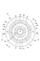
- FIG. 2 is a plan view of the antenna shown in FIG. 1 viewed from below.
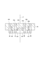
- 3 is an enlarged cross-sectional view of the metal plate and the plurality of protrusions of the antenna shown in FIG. 1 and 3 show a cross section of the metal plate 40 taken along the line III-III in FIG.
- the metal plate 40 is formed with a plurality of openings 40h penetrating the metal plate 40 in the axis Z direction.
- Some of the plurality of openings 40h extend along the first circle CC1 with the axis Z as the center. That is, the plurality of openings 40h along the first circle CC1 have an arc-like and belt-like shape along the first circle CC1 as a planar shape in a plane orthogonal to the axis Z.
- the other part of the plurality of openings 40h extends along the second circle CC2 having a diameter larger than the diameter of the first circle CC1 with the axis Z as the center. It is extended.
- the plurality of openings 40h along the second circle CC2 have an arc-like and belt-like shape along the second circle CC2 as a planar shape in a plane orthogonal to the axis Z.
- the plurality of openings 40h are provided symmetrically with respect to the axis Z.
- the antenna 14 further includes a plurality of protrusions 42 extending to the processing space S through the plurality of openings 40h.
- these protrusions 42 are in contact with the dielectric plate 38 at their upper ends and extend below the lower surface of the metal plate 40.
- each of the plurality of projecting portions 42 has a planar shape following the corresponding opening among the plurality of openings 40 h as a cross-sectional shape in a plane orthogonal to the axis Z. That is, the projecting portion 42 passing through the opening 40h provided along the first circle CC1 has an arc-like and strip-like cross-sectional shape that follows the planar shape of the corresponding opening provided along the first circle CC1. is doing. Further, the projecting portion 42 passing through the opening 40h provided along the second circle CC2 has an arc-shaped and belt-like cross-sectional shape that follows the planar shape of the corresponding opening provided along the second circle CC2. is doing.
- the plurality of protrusions 42 are made of a dielectric, and are made of, for example, quartz. Note that a film made of Y 2 O 3 or quartz may be provided on the lower surface of the metal plate 40, particularly on the region of the metal plate 40 facing the processing space S.
- the microwave generated by the microwave generator 28 is guided through the tuner 30, the waveguide 32, the mode converter 34, and the coaxial waveguide 16. It propagates to the WG, that is, the dielectric plate 38.
- the microwave propagated through the dielectric plate 38 becomes a standing wave in the waveguide WG.
- the microwave leaks from the waveguide WG to the plurality of protrusions 42 that pass through the plurality of openings 40 h of the metal plate 40 and is supplied to the processing space S.
- the microwave leaking from the metal plate 40 concentrates on the plurality of projecting portions 42 instead of the entire region below the metal plate 40.
- the plasma generation position of the processing gas is concentrated in the vicinity of the plurality of protrusions 42. Therefore, the plasma processing apparatus 10 is excellent in controllability of the plasma generation position.
- the plurality of projecting portions 42 are provided along concentric first and second circles, and are provided symmetrically about the axis Z. Therefore, in the plasma processing apparatus 10, the plasma generation position can be distributed in the radial direction with respect to the axis Z, and can be distributed in the circumferential direction on the axis Z. As a result, according to the plasma processing apparatus 10, the plasma density distribution in the circumferential direction and the radial direction with respect to the axis Z can be made uniform. Further, according to the plasma processing apparatus 10, not only can the plasma localization directly under the antenna 14 be generated when a large amount of processing gas is supplied directly under the antenna 14, but also in the supply of the processing gas with a medium to low flow rate, Optimal plasma density control can be realized.
- the plasma processing apparatus 10 may further include a plurality of plungers 44.
- Each of the plurality of plungers 44 includes a reflecting plate 44a and a position adjusting mechanism 44b.
- the reflecting plates 44a of the plurality of plungers 44 are provided so as to face the plurality of protrusions 42 provided along the first circle CC1 via the waveguide WG. Yes.
- the reflecting plate 44a of the plunger 44 is connected to a position adjusting mechanism 44b for adjusting the position in the axis Z direction.
- the position of the peak of the standing wave in the waveguide WG can be adjusted by adjusting the position of the reflecting plate 44a using the position adjusting mechanism 44b.
- the ratio of the power of the microwave that leaks to the protrusion 42 provided along the first circle CC1 and the power of the microwave that leaks to the protrusion 42 provided along the second circle CC1. Can be adjusted. This makes it possible to adjust the plasma density distribution in the radial direction with respect to the axis Z.
- the plurality of plungers 44 may be provided such that the plurality of protrusions 42 provided along the second circle CC2 and the reflection plate 44a face each other, or all of the plungers 44 may be provided.
- the protrusion 42 and the reflection plate 44a may be provided so as to face each other.
- the metal plate 40 is provided with a plurality of gas injection ports 40 i for supplying a processing gas to the processing space S. These gas injection ports 40i are opened downward.
- the plurality of gas injection ports 40i are arranged along two concentric circles centered on the axis Z.
- the metal plate 40 is formed with an annular gas line 40b connected to the gas injection ports 40i arranged along the inner circle of the two concentric circles.
- a gas line 40c extending toward the peripheral edge of the metal plate 40 is connected to the gas line 40b.
- the gas line 40 c is connected to a port 40 d provided on the lower surface of the metal plate 40.
- a gas source 25 is connected to the port 40d through a gas line provided in the side wall 12a of the processing container 12. Similar to the gas source 24c, the gas source 25 is a gas source of a processing gas, and is configured so that the flow rate of the processing gas can be controlled.
- the metal plate 40 is formed with an annular gas line 40e connected to the gas injection ports 40i arranged along the outer circle of the two concentric circles.
- a gas line 40f extending toward the peripheral edge of the metal plate 40 is connected to the gas line 40e.
- the gas line 40 f is connected to a port 40 g provided on the lower surface of the metal plate 40.
- a gas source 26 is connected to the port 40g via a gas line provided in the side wall 12a of the processing container 12.
- the gas source 26 is a gas source of a processing gas, and is configured to be able to control the flow rate of the processing gas.
- the processing gas is supplied from above the processing space S downward.
- a plurality of gas injection ports 40i are provided.
- the gas injection ports 40i are arranged along two concentric circles. Therefore, in the plasma processing apparatus 10, the processing gas can be supplied from above the processing space S toward the target substrate W, and the flow rate distribution of the processing gas in the radial direction with respect to the axis Z can be adjusted. Is possible.
- the plurality of gas injection ports 40i may be arranged along three or more concentric circles.
- a heater HT is provided on the cooling jacket 36.
- the heater HT heats the metal plate 40 via the cooling jacket 36.
- the antenna 14 can be cooled by the cooling jacket 36.
- the plasma processing apparatus 10 has been described in detail.
- the plasma processing apparatus 10 has the effect of excellent controllability of the plasma generation position. This effect is achieved at a high pressure such as 1 Torr (133.3 Pa) or more in the processing container 12. It is especially effective in some cases.
- a high pressure such as 1 Torr (133.3 Pa) or more in the processing container 12. It is especially effective in some cases.
- 1 Torr 133.3 Pa
- the behavior of the flow of electrons and ions constituting the plasma in the processing vessel 12 can be expressed by the following transport equation.
- the plasma does not contain negative ions.
- ⁇ , ⁇ e , and ⁇ i indicate the fluxes of plasma, electrons, and ions, respectively
- D is an ambipolar diffusion coefficient
- n is a plasma density.
- the ambipolar diffusion coefficient D can be expressed by the following equation (2).
- mu e, mu i respectively, electrons are the mobility of ions, D e, the D i are each electron diffusion coefficient of ions.
- the mobility and diffusion coefficient of the particle type s are expressed by the following equations (3) and (4), respectively.
- Equation (3) and (4) q s is the charge amount of the particle type s
- k B is the Boltzmann constant
- T s is the temperature of the particle type s
- m s is the mass of the particle type s
- ⁇ sm is the particle type s. It is the collision frequency between and neutral particles. Assuming that all ions are monovalent cations, substituting (3) and (4) into (2), It becomes.
- the pressure in the processing container 12 when the pressure in the processing container 12 is high and when the pressure is low, the same power microwave is input, and the generation amount of electrons and ions is equal. In case it is kept equal. Further, when the pressure in the processing container 12 increases, the collision frequency ⁇ sm between the particle type s and the neutral particles increases. From the equation (5), when the pressure in the processing container 12 increases, the ambipolar diffusion coefficient D Is smaller than the diffusion coefficient when the pressure in the processing container 12 is low. Therefore, from the relationship of the expression (1), in order to make the plasma flux ⁇ when the pressure in the processing container 12 is high equal to the plasma flux ⁇ when the pressure in the processing container 12 is low, it is strong. A plasma density gradient is required.
- the frequency of electrons causing inelastic collisions increases, and the travel distance from the generation of electrons to the loss of energy due to inelastic collisions is shortened. For this reason, when the pressure in the processing container 12 increases, a phenomenon that the plasma is localized may occur even if the plasma is diffused in a wide region.
- the plasma generation position is determined by the standing wave mode in the dielectric, and even if the microwave input position is defined by a slot plate, etc. It is difficult to obtain sufficient plasma generation position controllability.
- the plasma processing apparatus 10 since the microwaves are concentrated on the plurality of protrusions 42 whose area in contact with the processing space S is limited, the plasma generation position is located near the protrusions 42 even under high pressure. It is possible to control. Therefore, the plasma processing apparatus 10 is excellent in controllability of the plasma generation position even under high pressure.
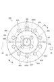
- FIG. 4 is a plan view of an antenna according to another embodiment as viewed from below.
- FIG. 5 is an enlarged cross-sectional view showing a metal plate and a plurality of protrusions of an antenna according to another embodiment, and shows a cross section taken along the line VV of FIG.
- a plurality of openings 40Ah are provided in the metal plate 40A of the antenna 14A shown in FIG.
- the plurality of openings 40Ah are arranged along the concentric circles CC1 and CC2, and are provided symmetrically about the axis Z.
- the plurality of openings 40Ah have a circular shape as a planar shape in a plane orthogonal to the axis Z.
- the antenna 14A has a plurality of protrusions 42A that are rod-shaped, that is, cylindrical, that pass through the plurality of openings 40Ah. These projecting portions 42A are in contact with the dielectric plate 38 at their upper ends, and extend in the axis Z direction downward from the lower surface of the metal plate 40A.
- the antenna 14 ⁇ / b> A having such a configuration has a plurality of cylindrical protrusions 42 ⁇ / b> A, but can exhibit the same effect as that exhibited by the antenna 14. Therefore, the plurality of protrusions may have any shape as long as they extend from the opening provided in the metal plate of the antenna to the lower side of the metal plate so as to contact the processing space S with a limited area.
- FIG. 6 is a perspective view showing the configuration of the plasma processing apparatus used in the experimental example.
- the plasma processing apparatus 100 shown in FIG. 6 includes four dielectric rods SP1 to SP4 at the top of the processing vessel 112.
- the rods SP1 to SP4 have a diameter of 40 mm and a length of 353 mm, and are arranged in parallel to each other at 100 mm intervals. Further, as shown in FIG. 6, these rods are arranged in one direction in the order of rods SP1, SP3, SP2, and SP4.
- the plasma processing apparatus 100 includes two rectangular waveguides 114 and 116.
- the cross-sectional size of the rectangular waveguides 114 and 116 is 109.2 mm ⁇ 54.6 mm in conformity with the EIA standard WR-430.
- the waveguides 114 and 116 extend in a direction orthogonal to the extending direction of the rods SP1 to SP4, and are provided so that the rods SP1 to SP4 are interposed therebetween.
- the waveguide 114 has a plunger 118 at its reflective end, and the waveguide 116 has a plunger 120 at its reflective end.
- rods SP1 and SP2 are located in the waveguide of the waveguide 114, and the other ends of the rods SP1 and SP2 are terminated before the waveguide of the waveguide 116. Specifically, one end of each of the rods SP1 and SP2 enters the waveguide 114 with a length of 30 mm. Further, one ends of the rods SP3 and SP4 are located in the waveguide of the waveguide 116, and the other ends of the rods SP3 and SP4 are terminated before the waveguide of the waveguide 114. Specifically, one end of each of the rods SP3 and SP4 enters the waveguide 116 with a length of 30 mm.
- the plunger 122 has a reflecting plate 122a and a position adjusting mechanism 122b.
- the reflecting plate 122a faces one end of the rod SP1 through the waveguide of the waveguide 114.
- the position adjusting mechanism 122b has a function of adjusting the position of the reflecting plate 122a from one surface (indicated by reference numeral 114a) of the waveguide 114 that defines the waveguide.
- the plunger 124 includes a reflecting plate 124a and a position adjusting mechanism 124b.
- the reflection plate 124a is opposed to one end of the rod SP2 through the waveguide of the waveguide 114.
- the position adjusting mechanism 124 b can adjust the position of the reflecting plate 124 a from the one surface 114 a of the waveguide 114.
- plungers 126 and 128 are attached to the waveguide 116.
- the plunger 126 has a reflecting plate 126a and a position adjusting mechanism 126b.
- the reflection plate 126a is opposed to one end of the rod SP3 through the waveguide of the waveguide 116.
- the position adjusting mechanism 126b can adjust the position of the reflector 126a from one surface (indicated by reference numeral 116a) of the waveguide 116 that defines the waveguide.
- the plunger 128 has a reflecting plate 128a and a position adjusting mechanism 128b.
- the reflection plate 128a is opposed to one end of the rod SP4 through the waveguide of the waveguide 116.
- the position adjusting mechanism 128b can adjust the position of the reflecting plate 128a from the one surface 116a of the waveguide 116 that defines the waveguide.
- the pressure in the processing container 112 was set to 100 mTorr (13.33 Pa), and in Experimental Example 2, the pressure in the processing container 112 was set to 1 Torr (133.3 Pa).
- the distance between the reflector 118a of the plunger 118 and the axis line of the rod SP1 was 85 mm.
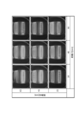
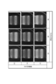
- FIG. 7 shows an image of the plasma emission state of Experimental Example 1
- FIG. 8 shows an image of the plasma emission state of Experimental Example 2.
- images obtained by photographing the light emission state of the plasma under the set values of the distance d1 and the distance d2 are shown in a matrix in association with the set values of the distance d1 and the distance d2.
- the relatively high luminance portion indicates the light emission of the plasma in the vicinity of the rods SP1 and SP2. Therefore, as a result of Experimental Example 1 and Experimental Example 2, it was confirmed that the plasma generation position can be controlled in the vicinity of the rods SP1 and SP2. From this, it is possible to concentrate the plasma generation position in the vicinity of the dielectric member by a configuration in which the dielectric member extending from the waveguide is in contact with the processing space in the processing container with a limited area. It was confirmed that it was possible.
- distances d1 and d2 that is, the distance of the reflecting plate 122a from the waveguide of the waveguide 114, and the distance of the reflecting plate 124a from the waveguide of the waveguide 114 It was confirmed that the ratio of the brightness of the plasma in the vicinity of the rod SP1 and the brightness of the plasma in the vicinity of the rod SP2 changes relatively by adjusting the. Therefore, as a result of Experimental Examples 1 and 2, it was confirmed that the ratio of the plasma density in the vicinity of the rod SP1 and the plasma density in the vicinity of the rod SP2 can be adjusted by adjusting the distances d1 and d2.
- the electric field strength of the plasma processing apparatus 100 was calculated by simulation with the same settings as in Experimental Example 1 and Experimental Example 2.
- the distance d1 and the distance d2 were changed as parameters
- the electric field strength P1 in the rod SP1 and the electric field strength P2 in the rod SP2 were calculated
- P1 / (P1 + P2) was obtained as the ratio of the electric field strength.
- FIG. 9 the horizontal axis represents the set value of the distance d1
- the vertical axis represents the set value of the distance d2.
- the ratio P1 / (P1 + P2) of the electric field intensity calculated under the setting value of the distance d1 and the setting value of the distance d2 is shown in association with the setting value of the distance d1 and the setting value of the distance d2. .
- the portion indicating the ratio P1 / (P1 + P2) of the electric field strength of the same set values as the set values of the distance d1 and the distance d2 in the experimental examples 1 and 2 is circled.
- the electric field intensity ratio P1 / (P1 + P2) in the portion surrounded by a circle in FIG. 9 is consistent with the plasma emission state of Experimental Examples 1 and 2.
- the density distribution of plasma concentrated in the vicinity of a plurality of dielectric members is adjusted by adjusting the distance from the waveguide of the reflector of the plunger. It was confirmed that it can be adjusted.
- the plurality of protrusions made of a dielectric are arranged along two concentric circles, that is, the first circle CC1 and the second circle CC2. It may be provided along the above concentric circles.
- DESCRIPTION OF SYMBOLS 10 Plasma processing apparatus, 12 ... Processing container, 14 ... Antenna, 28 ... Microwave generator, 36 ... Cooling jacket, 38 ... Dielectric plate, 40 ... Metal plate, 40h ... Opening, 40i ... Gas injection port, 42 ... Projection, 44 ... plunger, 44a ... reflector, 44b ... position adjusting mechanism, CC1 ... first circle, CC2 ... second circle, HT ... heater, WG ... waveguide, Z ... axis, 14A ... antenna, 40A ... Metal plate, 40Ah ... Opening, 42A ... Projection.
Landscapes
- Physics & Mathematics (AREA)
- Engineering & Computer Science (AREA)
- Plasma & Fusion (AREA)
- Chemical & Material Sciences (AREA)
- Analytical Chemistry (AREA)
- Spectroscopy & Molecular Physics (AREA)
- Electromagnetism (AREA)
- Chemical Kinetics & Catalysis (AREA)
- Materials Engineering (AREA)
- Mechanical Engineering (AREA)
- Metallurgy (AREA)
- Organic Chemistry (AREA)
- General Chemical & Material Sciences (AREA)
- Plasma Technology (AREA)
- Chemical Vapour Deposition (AREA)
- Drying Of Semiconductors (AREA)
Abstract
Description

ここで、プラズマは負イオンを含まないプラズマであるとする。(1)式において、Γ、Γe、Γiはそれぞれプラズマ、電子、イオンの流束を示しており、Dは両極性拡散係数であり、nは、プラズマ密度である。また、両極性拡散係数Dは、下記の(2)式で表わすことができる。

(2)式において、μe,μiはそれぞれ、電子、イオンの移動度であり、De,Diはそれぞれ電子、イオンの拡散係数である。粒子種sの移動度、拡散係数はそれぞれ以下の(3)式、(4)式で表される。


(3)、(4)式において、qsは粒子種sの電荷量、kBはボルツマン定数、Tsは粒子種sの温度、msは粒子種sの質量、νsmは粒子種sと中性粒子との衝突周波数である。イオンはすべて1価の陽イオンであると仮定し、(2)式に(3)、(4)式を代入すると、

Claims (7)
- 処理空間を画成する処理容器と、
前記処理空間の上方に設けられたアンテナであり、所定の軸線を中心とする円盤形状の導波路を有する該アンテナと、
前記アンテナに接続されたマイクロ波発生器と、
前記処理容器内に設けられたステージであり、前記所定の軸線と交差するよう前記処理空間を介して前記アンテナと対面する該ステージと、
を備え、
前記アンテナは、前記導波路を下方から画成する金属板を含み、
前記金属板には、前記所定の軸線を中心とする第1の円及び該所定の軸線を中心とし前記第1の円よりも大径の第2の円に沿って複数の開口が設けられており、
前記アンテナは、前記複数の開口を通って前記処理空間内に延び出した誘電体製の複数の突出部を含む、
プラズマ処理装置。 - 前記複数の突出部のうち、前記第1の円及び第2の円の少なくとも一方に沿って設けられた開口を通る突出部と前記導波路を介して対峙する反射板を有し、前記所定の軸線が延在する方向において前記導波路からの前記反射板の距離を調整可能なプランジャを更に備える、請求項1に記載のプラズマ処理装置。
- 前記金属板には、前記処理空間に処理ガスを供給するための複数のガス噴射口が設けられている、請求項1又は2に記載のプラズマ処理装置。
- 前記複数のガス噴射口は、前記所定の軸線を中心とする少なくとも二つの同心円に沿って設けられている、請求項1~3の何れか一項に記載のプラズマ処理装置。
- 前記導波路の上に設けられた冷却ジャケットと、
前記金属板を加熱するヒータと、
を更に備える、請求項1~4の何れか一項に記載のプラズマ処理装置。 - 前記複数の突出部は、前記所定の軸線が延在する方向に延びる棒状の誘電体により構成されており、該複数の突出部は、前記第1の円及び前記第2の円において前記所定の軸線に対して軸対称となるように配列されている、請求項1~5の何れか一項に記載のプラズマ処理装置。
- 前記複数の突出部は、前記所定の軸線に直交する断面において弧状の形状を有し、該複数の突出部は、前記第1の円及び前記第2の円において前記所定の軸線に対して軸対称となるように配列されている、請求項1~5の何れか一項に記載のプラズマ処理装置。
Priority Applications (2)
| Application Number | Priority Date | Filing Date | Title |
|---|---|---|---|
| US14/416,441 US20150194290A1 (en) | 2012-07-25 | 2013-04-12 | Plasma processing apparatus |
| KR20157000729A KR20150036045A (ko) | 2012-07-25 | 2013-04-12 | 플라즈마 처리 장치 |
Applications Claiming Priority (2)
| Application Number | Priority Date | Filing Date | Title |
|---|---|---|---|
| JP2012164833A JP2014026773A (ja) | 2012-07-25 | 2012-07-25 | プラズマ処理装置 |
| JP2012-164833 | 2012-07-25 |
Publications (1)
| Publication Number | Publication Date |
|---|---|
| WO2014017130A1 true WO2014017130A1 (ja) | 2014-01-30 |
Family
ID=49996949
Family Applications (1)
| Application Number | Title | Priority Date | Filing Date |
|---|---|---|---|
| PCT/JP2013/061067 Ceased WO2014017130A1 (ja) | 2012-07-25 | 2013-04-12 | プラズマ処理装置 |
Country Status (5)
| Country | Link |
|---|---|
| US (1) | US20150194290A1 (ja) |
| JP (1) | JP2014026773A (ja) |
| KR (1) | KR20150036045A (ja) |
| TW (1) | TW201419948A (ja) |
| WO (1) | WO2014017130A1 (ja) |
Families Citing this family (9)
| Publication number | Priority date | Publication date | Assignee | Title |
|---|---|---|---|---|
| JP2017004665A (ja) * | 2015-06-08 | 2017-01-05 | 東京エレクトロン株式会社 | プラズマ処理装置 |
| US20190151192A1 (en) | 2016-05-19 | 2019-05-23 | Yohachi Yamashita | Ultrasonic irradiation apparatus and system, and ultrasonic irradiation method |
| JP6850636B2 (ja) * | 2017-03-03 | 2021-03-31 | 東京エレクトロン株式会社 | プラズマ処理装置 |
| JP6960813B2 (ja) * | 2017-09-20 | 2021-11-05 | 東京エレクトロン株式会社 | グラフェン構造体の形成方法および形成装置 |
| JP7026498B2 (ja) * | 2017-12-12 | 2022-02-28 | 東京エレクトロン株式会社 | アンテナ及びプラズマ成膜装置 |
| KR102267544B1 (ko) * | 2018-01-05 | 2021-06-21 | 박상규 | 마이크로파 시스템 |
| JP7221115B2 (ja) * | 2019-04-03 | 2023-02-13 | 東京エレクトロン株式会社 | プラズマ処理方法及びプラズマ処理装置 |
| JP2024067696A (ja) * | 2022-11-07 | 2024-05-17 | 日新電機株式会社 | プラズマ処理装置 |
| US20250259819A1 (en) * | 2024-02-08 | 2025-08-14 | Tokyo Electron Limited | Apparatus for plasma processing |
Citations (5)
| Publication number | Priority date | Publication date | Assignee | Title |
|---|---|---|---|---|
| JPH10134995A (ja) * | 1996-10-28 | 1998-05-22 | Toshiba Corp | プラズマ処理装置及びプラズマ処理方法 |
| JP2004186303A (ja) * | 2002-12-02 | 2004-07-02 | Tokyo Electron Ltd | プラズマ処理装置 |
| JP2006040609A (ja) * | 2004-07-23 | 2006-02-09 | Naohisa Goto | プラズマ処理装置および方法、並びにフラットパネルディスプレイ装置の製造方法 |
| JP2007188722A (ja) * | 2006-01-12 | 2007-07-26 | Tokyo Electron Ltd | プラズマ処理装置 |
| WO2010140526A1 (ja) * | 2009-06-01 | 2010-12-09 | 東京エレクトロン株式会社 | プラズマ処理装置及びプラズマ処理装置の給電方法 |
Family Cites Families (11)
| Publication number | Priority date | Publication date | Assignee | Title |
|---|---|---|---|---|
| EP0264913B1 (en) * | 1986-10-20 | 1994-06-22 | Hitachi, Ltd. | Plasma processing apparatus |
| JP2993675B2 (ja) * | 1989-02-08 | 1999-12-20 | 株式会社日立製作所 | プラズマ処理方法及びその装置 |
| EP0688038B1 (en) * | 1994-06-14 | 2001-12-19 | Sumitomo Metal Industries, Ltd. | Microwave plasma processing system |
| JP4393844B2 (ja) * | 2003-11-19 | 2010-01-06 | 東京エレクトロン株式会社 | プラズマ成膜装置及びプラズマ成膜方法 |
| KR20050079860A (ko) * | 2004-02-07 | 2005-08-11 | 삼성전자주식회사 | 마이크로 웨이브 공급장치, 이를 이용한 플라즈마공정장치 및 플라즈마 공정방법 |
| JP2006324551A (ja) * | 2005-05-20 | 2006-11-30 | Shibaura Mechatronics Corp | プラズマ発生装置及びプラズマ処理装置 |
| JP4944198B2 (ja) * | 2007-06-11 | 2012-05-30 | 東京エレクトロン株式会社 | プラズマ処理装置および処理方法 |
| KR101196075B1 (ko) * | 2007-09-28 | 2012-11-01 | 도쿄엘렉트론가부시키가이샤 | 플라즈마 처리 장치 |
| JP5222744B2 (ja) * | 2009-01-21 | 2013-06-26 | 国立大学法人東北大学 | プラズマ処理装置 |
| JP2010277969A (ja) * | 2009-06-01 | 2010-12-09 | Tokyo Electron Ltd | プラズマ処理装置及びプラズマ処理装置の給電方法 |
| US8415884B2 (en) * | 2009-09-08 | 2013-04-09 | Tokyo Electron Limited | Stable surface wave plasma source |
-
2012
- 2012-07-25 JP JP2012164833A patent/JP2014026773A/ja active Pending
-
2013
- 2013-04-12 WO PCT/JP2013/061067 patent/WO2014017130A1/ja not_active Ceased
- 2013-04-12 US US14/416,441 patent/US20150194290A1/en not_active Abandoned
- 2013-04-12 KR KR20157000729A patent/KR20150036045A/ko not_active Withdrawn
- 2013-07-19 TW TW102125942A patent/TW201419948A/zh unknown
Patent Citations (5)
| Publication number | Priority date | Publication date | Assignee | Title |
|---|---|---|---|---|
| JPH10134995A (ja) * | 1996-10-28 | 1998-05-22 | Toshiba Corp | プラズマ処理装置及びプラズマ処理方法 |
| JP2004186303A (ja) * | 2002-12-02 | 2004-07-02 | Tokyo Electron Ltd | プラズマ処理装置 |
| JP2006040609A (ja) * | 2004-07-23 | 2006-02-09 | Naohisa Goto | プラズマ処理装置および方法、並びにフラットパネルディスプレイ装置の製造方法 |
| JP2007188722A (ja) * | 2006-01-12 | 2007-07-26 | Tokyo Electron Ltd | プラズマ処理装置 |
| WO2010140526A1 (ja) * | 2009-06-01 | 2010-12-09 | 東京エレクトロン株式会社 | プラズマ処理装置及びプラズマ処理装置の給電方法 |
Also Published As
| Publication number | Publication date |
|---|---|
| KR20150036045A (ko) | 2015-04-07 |
| US20150194290A1 (en) | 2015-07-09 |
| JP2014026773A (ja) | 2014-02-06 |
| TW201419948A (zh) | 2014-05-16 |
Similar Documents
| Publication | Publication Date | Title |
|---|---|---|
| WO2014017130A1 (ja) | プラズマ処理装置 | |
| JP5808697B2 (ja) | ドライエッチング装置及びドライエッチング方法 | |
| JP5717888B2 (ja) | プラズマ処理装置 | |
| US5938883A (en) | Plasma processing apparatus | |
| KR102523730B1 (ko) | 이중 주파수 표면파 플라즈마 소스 | |
| KR101008746B1 (ko) | 플라즈마 처리 장치 및 플라즈마 처리 방법 | |
| US20040219737A1 (en) | Method and apparatus for processing a workpiece with a plasma | |
| JP5630667B2 (ja) | 基板処理装置 | |
| JP7085828B2 (ja) | プラズマ処理装置 | |
| JPH088095A (ja) | プラズマ処理用高周波誘導プラズマ源装置 | |
| JP2012238845A (ja) | プラズマ処理装置 | |
| JP5522887B2 (ja) | プラズマ処理装置 | |
| JP3254069B2 (ja) | プラズマ装置 | |
| KR20140103844A (ko) | 플라즈마 처리 장치 | |
| US20140251541A1 (en) | Plasma processing apparatus | |
| JP2019110047A (ja) | プラズマ処理装置 | |
| US10665428B2 (en) | Plasma processing apparatus | |
| JP4900768B2 (ja) | プラズマ発生装置及びプラズマ処理装置 | |
| JP2019160519A (ja) | アンテナ装置、および、プラズマ処理装置 | |
| JP2001015297A (ja) | プラズマ装置 | |
| KR101434145B1 (ko) | 멀티 레이저 스캐닝 라인을 갖는 유도 결합 플라즈마반응기 | |
| JP2920852B2 (ja) | マイクロ波プラズマ装置 | |
| JP7760389B2 (ja) | プラズマ処理装置 | |
| JP2016091603A (ja) | マイクロ波プラズマ処理装置 | |
| JP5382958B2 (ja) | プラズマ発生装置及びプラズマ処理装置 |
Legal Events
| Date | Code | Title | Description |
|---|---|---|---|
| 121 | Ep: the epo has been informed by wipo that ep was designated in this application |
Ref document number: 13822615 Country of ref document: EP Kind code of ref document: A1 |
|
| ENP | Entry into the national phase |
Ref document number: 20157000729 Country of ref document: KR Kind code of ref document: A |
|
| WWE | Wipo information: entry into national phase |
Ref document number: 14416441 Country of ref document: US |
|
| NENP | Non-entry into the national phase |
Ref country code: DE |
|
| 122 | Ep: pct application non-entry in european phase |
Ref document number: 13822615 Country of ref document: EP Kind code of ref document: A1 |