WO2014016884A1 - 計算機システム、データ処理方法、及び、記録媒体 - Google Patents
計算機システム、データ処理方法、及び、記録媒体 Download PDFInfo
- Publication number
- WO2014016884A1 WO2014016884A1 PCT/JP2012/068565 JP2012068565W WO2014016884A1 WO 2014016884 A1 WO2014016884 A1 WO 2014016884A1 JP 2012068565 W JP2012068565 W JP 2012068565W WO 2014016884 A1 WO2014016884 A1 WO 2014016884A1
- Authority
- WO
- WIPO (PCT)
- Prior art keywords
- procedure
- flowchart
- node
- flow
- identifiers
- Prior art date
Links
Images


Classifications
-
- G—PHYSICS
- G06—COMPUTING; CALCULATING OR COUNTING
- G06Q—INFORMATION AND COMMUNICATION TECHNOLOGY [ICT] SPECIALLY ADAPTED FOR ADMINISTRATIVE, COMMERCIAL, FINANCIAL, MANAGERIAL OR SUPERVISORY PURPOSES; SYSTEMS OR METHODS SPECIALLY ADAPTED FOR ADMINISTRATIVE, COMMERCIAL, FINANCIAL, MANAGERIAL OR SUPERVISORY PURPOSES, NOT OTHERWISE PROVIDED FOR
- G06Q10/00—Administration; Management
- G06Q10/06—Resources, workflows, human or project management; Enterprise or organisation planning; Enterprise or organisation modelling
Definitions
- the present invention relates to a computer system, and more particularly to a non-primary recording medium storing a computer system for generating a flowchart, a data processing method, and a data processing program.
- the business procedure expressed by the flowchart includes a business procedure that tends to be an individual, or knowledge and know-how held by an employee.
- Patent Document 1 cannot automatically generate a “prepared flowchart” necessary for generating a partial flow. That is, even when the method described in Patent Document 1 is used, a person has to create a “prepared flowchart”, and as a result, a cost for creating the flowchart is required.
- the created flowchart may indicate a process flow (path) that is not actually executed. This occurs when a flowchart is created by a person, independently of the flow of processing actually executed in the computer system.
- the flow of processing that is not actually executed in this way has a problem that it is difficult for a person to notice when creating a flowchart, and that the flow of work is difficult to understand when employees use the flowchart.
- the present invention aims to provide a system for automatically generating a flowchart in accordance with a person's business in order to solve the above-described problems.
- a computer system having a processor and a memory, the computer system including an identifier indicating a plurality of executed processes, and each of the processes is executed.
- a plurality of execution paths indicating an order, and a flow generation unit that generates a flowchart based on each of the execution paths, wherein the flow generation unit has the same number of the processes as the first process executed are extracted from the plurality of execution paths, a first determination is performed to determine whether or not the identifiers of the extracted processes are the same, and the result of the first determination
- a common process symbol including the same process identifier is generated, and as a result of the first determination, the extracted process identifiers Out of If at least one is different from the other identifiers, a plurality of non-common processing symbols each including an identifier of the extracted processing, which is determined to be at least one different in the first determination, are generated and the generated
- the flowchart including at least one of the common
- FIG. 6 is a flowchart illustrating processing for generating a flowchart from an execution path according to the first exemplary embodiment. It is explanatory drawing which shows the example of a display of the flowchart produced
- the computer system according to the first embodiment generates a flowchart according to the work on the business system actually performed by the user.
- FIG. 1 is a block diagram illustrating a computer system according to the first embodiment.
- the computer system includes a flow generation server 10, an execution server 20, a network 150, and a client 160.
- the execution server 20 is a computer system that provides a service to the client 160 via the network 150 by executing a business system implemented by a program.
- the execution server 20 includes a processor 173, an auxiliary storage device 172, and a main storage device 170.
- the client 160 is a computer system for a user to work using a service provided by the execution server 20.
- the client 160 includes a processor 163 and a main storage device 161 and is connected to the input device 120 and the output device 130.
- the flow generation server 10 is a computer system that generates a flowchart showing a user's work procedure based on an input from the client 160.
- the flow generation server 10 includes a processor 140, a main storage device 100, and an auxiliary storage device 110.
- the network 150 is a network for connecting the execution server 20, the client 160, and the flow generation server 10.
- the network 150 may be a network such as the Internet, a LAN, or a WAN, for example.
- the processor 173 in the execution server 20 is an arithmetic device such as a CPU, and executes a program by reading data stored in the auxiliary storage device 172, a source program, and the like into the main storage device 170.
- the auxiliary storage device 172 holds data, source programs, and the like.
- the main storage device 170 is a storage area that holds a program executed by the processor.
- the main storage device 170 holds a travel expense application system 171.
- the travel expense application system 171 is a business system implemented by a program, and provides a service to a user in the first embodiment.
- the service provided by the travel expense application system 171 is referred to as travel expense application work.
- the processor 163 in the client 160 is an arithmetic device such as a CPU, and executes a program using the main storage device 161.
- the main storage device 161 holds a program executed by the processor.
- the main storage device 161 holds a screen display unit 162.
- the screen display unit 162 is a program for displaying the execution result of the travel expense application system 171 of the execution server 20 on the output device 130.
- the screen display unit 162 receives an instruction from the user via the input device 120. Then, the screen display unit 162 transmits an instruction from the user to the execution server 20 via the network 150.
- the processor 140 of the flow generation server 10 is an arithmetic device such as a CPU.
- the processor 140 executes the program by reading data stored in the auxiliary storage device 110, a source program, and the like into the main storage device 100.
- the auxiliary storage device 172 stores a node storage table 111, an execution path storage table 112, and a flow storage table 113.
- the node storage table 111 includes nodes indicating processing executed in the travel expense application system 171.
- the node in this embodiment is data indicating processing executed in the business system.
- One node represents one process.
- the process in the present embodiment indicates a process executed by a user's work. For this reason, one operation by the user corresponds to one node.
- the execution path storage table 112 is a table including execution paths.
- the execution path in the present embodiment indicates the executed node and the order in which the nodes are executed.
- the flow storage table 113 is a table for storing a flowchart generated in the flow generation server 10.
- the main storage device 100 holds a node generation unit 101, a node display unit 102, an execution path generation unit 103, a flow generation unit 104, and a flow display unit 105.
- the node generation unit 101 is a program for generating a node from the business system (travel expense application system 171).
- the node display unit 102 is a program for displaying the nodes stored in the node storage table 111 on the output device 130 connected to the client 160.
- the execution path generation unit 103 is a program that generates an execution path based on information indicating the executed node.
- the flow generation unit 104 is a program that generates a flowchart based on the execution paths stored in the execution path storage table 112.
- the flow display unit 105 is a program for causing the output device 130 connected to the client 160 to display the flowchart stored in the flow storage table 113.
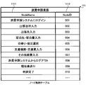
- FIG. 2 is an explanatory diagram illustrating the node storage table 111 according to the first embodiment.
- the node storage table 111 includes a node name 1111 and a node ID 1112. Each entry in the node storage table 111 indicates each node.
- the node name 1111 includes a name indicating each node.
- the name included in the node name 1111 is a character string that allows the user to identify the content of the process.
- the node ID 1112 is an identifier that uniquely indicates each node.
- the node generation unit 101 generates a node based on the travel expense application system 171 based on the travel expense application system 171, and stores the generated node in the node storage table 111.
- the node generation unit 101 may extract, for example, a source program indicating a process for causing the user to select a process from the travel expense application system 171.
- the node generation unit 101 stores, in the node name 1111, the name of the process selected by the user (such as the name of the screen displayed to the user) included in the extracted source program. Then, the node generation unit 101 assigns a unique identifier to the node ID 1112 of the entry whose value is stored in the node name 1111.
- the node display unit 102 transmits the node name indicated by the node name 1111 to the screen display unit 162 of the client 160.
- the screen display unit 162 displays the transmitted node name on the output device 130.
- the user selects the node name displayed on the output device 130 with the input device 120. For example, when the travel expense application system 171 is executed, the user selects a node name according to the order of work performed by the user.
- the screen display unit 162 receives the node name selected by the user, and transmits the selected node name to the execution path generation unit 103.
- the screen display unit 162 may transmit the received node name to the travel expense application system 171 and cause the travel expense application system 171 to execute processing.
- FIG. 3 is an explanatory diagram illustrating processing for generating an execution path according to the first embodiment.
- the node selection result 40 shown in FIG. 3 indicates the node name displayed to the user, the node name selected by the user, and the order in which the user selected the node name.
- the node selection result 40 includes nodes 40a to 40j.
- Nodes 40a to 40j are node names displayed to the user by the screen display unit 162.
- the node selection result 40 illustrated in FIG. 3 indicates that the user has selected processing in the order of the node 40a, the node 40b, the node 40d, the node 40e, the node 40f, the node 40g, the node 40h, and the node 40j.
- the execution path generation unit 103 generates the node selection result 40 based on the node name and the order in which the node names are selected transmitted from the screen display unit 162.
- the execution path generation unit 103 generates an execution path 41 based on the node selection result 40.
- the execution path 41 is an array including, as elements, a node ID corresponding to the selected node name.
- the execution path 41 has node IDs in the order in which the node names indicated by the node selection result 40 are selected.
- the execution path generation unit 103 refers to the node selection result 40 and the node storage table 111, and extracts the node ID 1112 of the entry including the node name of the node selection result 40 in the node name 1111. As a result, the execution path generation unit 103 stores the node ID corresponding to the node name in the execution path 41.
- execution path 41 shown in FIG. 3 includes only the node ID, but each element of the execution path 41 may include a node ID and a node name.
- the execution path of this embodiment has element numbers (not shown) in order from the top of each element.
- an element number of 1 is assigned to the first element of the array. The element number increases by 1 as the number of elements increases by one.
- FIG. 4 is an explanatory diagram illustrating the execution path storage table 112 according to the first embodiment.
- execution path storage table 112 the execution path generated by the execution path generation unit 103 is stored for each business system in which the node indicated by the execution path is executed.
- the execution path storage table 112 shown in FIG. 4 includes the execution path of the travel expense application system 171.
- Execution paths of the travel expense application system 171 in FIG. 4 are an execution path 41 and an execution path 42.
- FIG. 5 is a flowchart illustrating processing for generating a flowchart from the execution path according to the first embodiment.
- the flow generation unit 104 starts the processing shown in FIG. 5 periodically or at a timing such as when an instruction from an administrator or the like is received.
- the flow generation unit 104 first acquires all execution paths from the execution path storage table 112 (601).
- execution paths relating to a plurality of business systems are stored in the execution path storage table 112, the flow generation unit 104 acquires all execution paths of the business system that generates the flowchart in accordance with an instruction from an administrator or the like.
- the flow generation unit 104 holds the parameter i in the main storage device 100. Then, the flow generation unit 104 stores 1 as an initial value in the parameter i (602).
- the parameter i indicates an element number in the execution path.
- the flow generation unit 104 extracts the element having the element number indicated by the parameter i in each execution path acquired in step 601. Then, the extracted elements are compared with each other. Then, as a result of the comparison, the flow generation unit 104 determines whether or not the node IDs of the elements having the element number indicated by the parameter i match in each execution path (603).
- the flow generation unit 104 determines that there is an element with a different node ID among the elements with the element number indicated by the parameter i even if any execution path does not include the element with the element number indicated by the parameter i. It's okay. Thus, even when the number of elements included in each execution path is different, the flow generation unit 104 can execute the processing shown in FIG.
- the flow generation unit 104 uses the same node name and the same node ID as the elements having the element numbers indicated by the parameters i.
- One node (common node) is generated.
- the flow generation unit 104 generates a symbol indicating the common node in order to express the common node in the flowchart (604).
- step 604 when there is a common node generated in step 604 executed last time, the flow generation unit 104 connects the symbol of the previously generated common node and the symbol of the newly generated common node with an arrow. To do.
- the arrow for connecting the common node symbols used in step 604 indicates that the flow of processing proceeds from the previously generated common node to the newly generated common node.
- step 604 the flow generation unit 104 adds 1 to the parameter i (605), and returns to step 603.
- step 603 If the result of determination in step 603 is that there is an element with a different node ID among the elements of the element number indicated by the parameter i in each execution path, the flow generation unit 104 generates a branch node. Further, the flow generation unit 104 generates a symbol indicating the branch node in order to represent the branch node in the flowchart (606).
- the branch node is a node indicating that the process flow executed by the common node branches into a plurality of different process flows according to a predetermined condition.
- the branch node is a node indicating that the process is divided by the determination by the user or the determination by the system.
- step 606 when there is a common node that has already been generated, the flow generation unit 104 connects the symbol indicating the last generated common node and the symbol indicating the generated branch node with an arrow.
- the arrow connecting the common node symbol and the branch node symbol used in step 606 indicates that the processing flow advances from the common node to the branch node.
- the flow generation unit 104 extracts an element having an element number equal to or greater than the value indicated by the parameter i for each execution path.
- the flow generation unit 104 extracts a plurality of elements having an element number equal to or greater than the value indicated by the parameter i for each execution path.
- the flow generation unit 104 generates a node (non-common node) having the extracted node name and node ID of each execution path for each execution path (607).
- the flow generation unit 104 generates a symbol indicating a non-common node.
- a plurality of non-common nodes generated for each execution path are described as a non-common node group. Non-common nodes are included in the non-common node group according to the execution order indicated by each execution path.
- step 607 the flow generation unit 104 connects the symbol of the branch node generated in step 606 and the symbol of the leading non-common node of the non-common node group with an arrow.
- the arrow connecting the branch node symbol and the non-common node symbol used in step 607 indicates that the processing flow branches from the branch node to each non-common node.
- step 607 when the non-common node group includes a plurality of non-common nodes, the flow generation unit 104 connects the symbols of the non-common nodes with arrows indicating the order of execution.
- the flow generation unit 104 can generate a flowchart including a symbol indicating a common node or a symbol indicating a non-common node. Therefore, the flow generation unit 104 stores the generated flowchart in the flow storage table 113 in step 607.
- FIG. 6 is an explanatory diagram illustrating a display example of the flowchart 50 generated by the flowchart generation processing according to the first embodiment.
- FIG. 6 shows a flowchart 50 generated by the processing shown in FIG. 5 and a screen example when the flowchart 50 is displayed on the output device 130.
- the flowchart 50 includes a common node 51, a branch node 52, and a non-common node 53.
- the common node 51 indicates a common node generated in step 604 shown in FIG. 5, and the branch node 52 indicates a branch node generated in step 606 shown in FIG.
- non-common node 53 indicates a non-common node generated in step 607 shown in FIG.
- the non-common node 53 illustrated in FIG. 6 includes two non-common node groups.
- the flow display unit 105 may transmit the flowchart 50 illustrated in FIG. 6 to the client 160 and cause the output device 130 to display the flowchart 50 via the screen display unit 162. Further, the screen display unit 162 may display the flowchart 50 shown in FIG. 6 together with the execution result of the processing by the travel expense application system 171.
- the user can grasp which process in the work procedure is being executed in the travel expense application work provided by the travel expense application system 171 by referring to the flowchart 50. As a result, the user can perform the work efficiently and accurately.
- the flow generation unit 104 described above generates a flowchart expressed by symbols and the like shown in FIG. 6, but if the user can recognize the flow of processing, the flowchart expressed by symbols and the like other than the flowchart shown in FIG. It may be generated.
- the flow generation unit 104 may represent an arrow with a straight line if the user can recognize the flow of processing.
- the computer system generates a flowchart according to the work actually performed by the user. Therefore, the computer system can generate a highly accurate flowchart including only the flow of the actually performed process. For this reason, when the user refers to the flowchart generated by the first embodiment, the user can accurately grasp the work procedure.
- the computer system of the first embodiment can reduce the labor and time for creating the flowchart.
- the configuration of the computer system in the second embodiment is the same as that of the first embodiment shown in FIG.
- the difference between the second embodiment and the first embodiment is only the flowchart generation processing by the flow generation unit 104.
- FIG. 7 is a flowchart showing a process for generating the flowchart of the second embodiment.
- steps 801 to 805 are the same as steps 601 to 605 shown in FIG. 5. For this reason, only processing different from the processing shown in FIG. 5 will be described below.
- the flow generation unit 104 determines the element number of the last element in each execution path. j is acquired (806). The element number j may have a different value depending on the execution path.
- the flow generation unit 104 extracts the element with the element number j acquired in step 806 from each execution path, and compares the node IDs of the extracted elements with each other. Then, as a result of the comparison, the flow generation unit 104 determines whether all the node IDs of the element with the element number j in each execution path match (807).
- step 807 when all the node IDs of the element with element number j match, the flow generation unit 104 generates one common node including the same node ID and node name as the element with element number j of each execution path. In addition, the flow generation unit 104 generates a symbol indicating the common node (808).
- step 808 when there is a common node generated in step 808 executed last time, the flow generation unit 104 connects the previously generated common node symbol and the newly generated common node symbol by an arrow. To do.
- the arrow for connecting the common node symbols used in step 808 indicates that the flow of processing proceeds from the newly generated common node to the previously generated common node.
- step 809 the flow generation unit 104 subtracts 1 from the element number j of each execution path (809). After step 809, the flow generation unit 104 returns to step 807.
- step 807 if even one node ID of the element of element number j of each execution path is different, the flow generation unit 104 generates a branch node.
- the flow generation unit 104 generates a symbol indicating a branch node and a merging point (810).
- the junction point in the present embodiment is a symbol indicating that the flow of a plurality of processes executed by the non-common node continues to one common process.
- step 810 the flow generation unit 104 connects the symbol of the common node generated last in step 804 and the symbol of the branch node by an arrow.
- the arrow connecting the common node symbol and the branch node symbol used here indicates that the flow of processing proceeds from the common node to the branch node.
- step 810 the flow generation unit 104 connects the last generated common node in step 808 to the junction point by an arrow.
- the arrow connecting the common node symbol and the merge point used here indicates that the flow of processing proceeds from the merge point to the common node.
- the flow generation unit 104 extracts the elements from the element number j to the parameter i of each execution path for each execution path. Then, the flow generation unit 104 generates a non-common node including the node name and node ID of each extracted element for each execution path. In addition, the flow generation unit 104 generates a symbol indicating a non-common node (811). Each generated non-common node is included in a plurality of non-common node groups as in the first embodiment.
- step 811 the flow generation unit 104 connects the symbol of the leading non-common node of each generated non-common node group and the symbol of the branch node generated in step 810 with an arrow.
- the arrow connecting the branch node symbol and the non-common node symbol used here indicates that the flow of processing branches from the branch node to each non-common node.
- step 811 the flow generation unit 104 connects the symbol of the non-common node at the end of the generated non-common node group and the confluence with an arrow.
- the arrow connecting the symbol of the non-common node and the merging point used here indicates that the flow of processing proceeds from the non-common node to the merging point.
- the flow generation unit 104 generates a flowchart through the above-described processing.
- the flow generation unit 104 stores the generated flowchart in the flow storage table 113.
- FIG. 8 is an explanatory diagram illustrating a display example of the flowchart 60 generated by the flowchart generation processing of the second embodiment.
- FIG. 8 shows a flowchart 60 generated by the process shown in FIG. 7 and an example in which the flowchart 60 is displayed.
- the flowchart 60 includes a common node 61, a branch node 62, a non-common node 63, a meeting point 64, and a common node 65.
- the common node 61 indicates a common node generated in step 804 shown in FIG. 7, and the branch node 62 indicates a branch node generated in step 810 shown in FIG.
- non-common node 63 indicates a non-common node generated in step 811 shown in FIG.
- the non-common node 63 includes two non-common node groups.
- the common node 65 corresponds to a non-common node at the end of the non-common node 53 illustrated in FIG.
- merge point 64 is a merge point generated in step 810 shown in FIG.
- the common node 65 is a common node generated in step 808 shown in FIG.
- the flow display unit 105 may display the flowchart 60 stored in the flow storage table 113 on the output device 130 via the screen display unit 162.
- the flow generation unit 104 described above generates a flowchart represented by symbols and the like shown in FIG. 8, but if the user can recognize the flow of processing, the flowchart represented by symbols and the like other than the flowchart shown in FIG. It may be generated.
- the merge point 64 may be represented by a combined arrow.
- the process included in the flowchart as a non-common node in the first embodiment can also be included in the flowchart as a common node.
- the computer system according to the second embodiment can generate a flowchart in which the user can easily grasp the work procedure.
- the computer system determines whether or not it is necessary to generate a flowchart again based on a flowchart given in advance and an execution path. As a result, even when a flowchart has already been generated, it is possible to correct a flowchart that does not accurately represent the work actually performed by the user.
- FIG. 9 is a block diagram illustrating the computer system of the third embodiment.
- the computer system shown in FIG. 9 has only a configuration for performing the processing of the third embodiment.
- the computer system according to the third embodiment includes at least the flow generation server 10, the network 150, and the client 160.
- the client 160 according to the third embodiment is a computer that has the same physical configuration as the client 160 according to the first embodiment, receives instructions from the user, and displays a flowchart to the user.
- the network 150 in the third embodiment is the same as the network 150 in the first embodiment.
- the flow generation server 10 includes the processor 140, the main storage device 100, and the auxiliary storage device 110, as in the first embodiment.
- the main storage device 100 according to the third embodiment includes a test history recording unit 201, a flow development unit 202, a flow comparison unit 203, a flow regeneration unit 204, and a flow display unit 105.
- the test history recording unit 201 is a program that generates an execution path indicating processing executed in the test.
- the flow development unit 202 is a program that analyzes a flowchart given in advance and calculates the number of processing flows (routes) based on the flowchart.
- the flow comparison unit 203 is a program that determines whether or not the number of processing flows calculated based on the flowchart and the number of execution paths are the same.
- the flow regeneration unit 204 is the same as the flow generation unit 104 of the first and second embodiments, and is a program that generates a flowchart based on the execution path.
- the flow display unit 105 is the same as the flow display unit 105 of the first and second embodiments.
- the auxiliary storage device 110 includes a test history table 211 and a flow storage table 113.
- the flow storage table 113 is a table for holding a flowchart generated by the processing of the third embodiment.
- the test history table 211 is a table for holding execution paths in the third embodiment.
- the test history table 211 corresponds to the execution path storage table 112 of the first and second embodiments.
- the flow generation server 10 can perform the processing of the first embodiment or the second embodiment and the third embodiment.
- the flow generation server 10 uses the program and table shown in FIG. 1 and the program shown in FIG.
- the computer system shown in FIG. 9 may have an execution server 20.
- FIG. 10 is an explanatory diagram showing an outline of processing by the computer system of the third embodiment.
- the computer system according to the third embodiment generates a flowchart relating to the business A (corresponding to the travel expense application system 171 according to the first and second embodiments) by the processing described below.
- the user in the third embodiment creates a flowchart of the job A to be tested (71).
- the flowchart created here is input to the client 160.
- Each symbol included in the flowchart is assigned a node including a node name and a node ID by a program of the client 160 or by a user.
- the user transmits the flowchart created by the user to the flow generation server 10 via the client 160, the network 150, and the like.
- the flow generation server 10 receives the flowchart created by the user (72).
- the user tests the job A using the client 160 based on the flowchart created in step 71 (73). For example, in step 73, the user displays the created flowchart on the output device 130 of the client 160, and displays each symbol of the flowchart indicating the flow of processing that needs to be tested according to the test items held in advance by the user. select.
- the client 160 transmits the node name and node ID of the node indicated by each symbol selected by the user to the flow generation server 10.
- the test history recording unit 201 After step 73 or during execution of step 73, the test history recording unit 201 generates an execution path based on the node name and node ID transmitted from the client 160. Then, the test history recording unit 201 stores the generated execution path in the test history table 211 (74).
- the test history recording unit 201 generates n execution paths (n is an arbitrary positive number).
- execution paths T1 to Tn are stored as test execution results. Similar to the execution path of the first embodiment, the execution paths T1 to Tn include a plurality of arrays including node IDs and node names.
- the flow development unit 202 analyzes the flowchart received in step 72, and calculates the number of processing flows represented by the flowchart as a result of the analysis (75). In step 75 shown in FIG. 10, the flow development unit 202 calculates the number m of process flows.
- the flow comparison unit 203 determines whether or not the number n of execution paths generated in step 74 is the same as the number m of process flows calculated in step 75 (76). When the number m of process flows and the number n of execution paths are the same number, there is no need to change the flowchart received by the flow regeneration unit 204 in step 72. Therefore, the flow comparison unit 203 ends the process shown in FIG. 10 (78).
- the flow regeneration unit 204 regenerates the flowchart relating to the job A by the process of generating the flowchart shown in the first embodiment or the second embodiment (77).
- the process for regenerating the flowchart executed in step 77 is the same as the process shown in FIG. 5 of the first embodiment or the process shown in FIG. 7 of the second embodiment.
- the flow regeneration unit 204 regenerates the flowchart using the execution path stored in the test history table 211 instead of the execution path storage table 112 by the process illustrated in FIG. 5 or FIG.
- the flow display unit 105 transmits the regenerated flowchart to the screen display unit 162 of the client 160, and the screen display unit 162 displays the regenerated flowchart on the output device 130. May be. Further, when the computer system shown in the third embodiment has the execution server 20 as in the computer system of the first or second embodiment, the regenerated flowchart and the screen of the job A executed in the execution server 20 are displayed. You may display simultaneously.
- the flowchart for calculating the processing flow in step 75 is a flowchart created by the user, but is generated by the processing for generating the flowchart in the first or second embodiment. It may be a flowchart.
- the computer system of the third embodiment regenerates the flowchart when a time has elapsed since the flowchart was generated by the processing in the first embodiment or the second embodiment and the work procedure by the user differs from the flowchart. May be.
- the flow development unit 202 may acquire the flowchart stored in the flow storage table 113 in step 75 and calculate the processing flow of the acquired flowchart.
- FIG. 11 is an explanatory diagram showing a flowchart 80 created by the user of the third embodiment.
- a flowchart 80 shown in FIG. 11 is a specific example of a flowchart created by the user and received by the flow generation server 10 in step 72.
- the flow development unit 202 calculates the number m of process flows based on the flowchart 80.
- the flowchart 80 includes a common node 81, a branch node 82, a non-common node 83, a common node 85, a branch node 86, a non-common node 87, and a termination node 89.
- the end node in this embodiment is a node that has no processing to be executed after the processing of the own node is completed.
- the flowchart 80 includes routes A to F.
- the route A is a route through which the process proceeds through the first connection destination of the branch node 82 (the connection destination on the left side shown in FIG. 11).
- the route B is a route in which the process proceeds along the route A and the first connection destination of the branch node 86 (the connection destination on the left side in FIG. 11).
- the route C is a route in which the process proceeds along the route A and the second connection destination of the branch node 86 (the connection destination on the right side shown in FIG. 11).
- the route D is a route through which processing proceeds through the second connection destination of the branch node 82 (the connection destination on the right side shown in FIG. 11) and passes through the first connection destination of the branch node 86.
- the route E is a route in which the process proceeds along the route D and the first connection destination of the branch node 86.
- the route F is a route in which the process advances along the route D and advances along the second connection destination of the branch node 86.
- FIG. 12 is an explanatory diagram showing the flow of processing included in the flowchart 80 of the third embodiment.
- a plurality of paths B, C, E, and F shown in FIG. 12 show the flow of all processes shown in the flowchart 80 shown in FIG.
- FIG. 13 is an explanatory diagram illustrating the branch information 90 regarding the connection destination of the branch node according to the third embodiment.
- the branch information 90 is an array held in the main storage device 100 for each branch node included in the flowchart.
- the flow development unit 202 holds the same number of branch information 90 as the number of branch nodes included in the flowchart 80 in the main storage device 100.
- Branch information 90 includes a branch ID 91 and a connection array.
- the branch ID 91 includes an identifier assigned to each branch node included in the flowchart 80.
- connection array indicates a path that the process proceeds from the branch node indicated by the branch ID 91.
- the connection arrangement shown in FIG. 13 includes a path 1 (92), a path 2 (93), and a NULL 94 as elements.
- Route 1 (92) is an element indicating the first connection destination of the branch node.
- Path 2 (93) is an element indicating the second connection destination of the branch node.
- the branch information 90 shown in FIG. 13 indicates the branch information 90 when the branch node is connected to two connection destinations.
- the connection array includes at least the same number of elements as the number of connection destinations to be connected.
- NULL94 includes a NULL value and is stored at the end of the connection array.
- the flow development unit 202 uses the branch information 90 to calculate the number of processes included in the flowchart.
- FIG. 14 is a flowchart showing a process for calculating the number of processes in the flowchart 80 of the third embodiment.
- the processing shown in FIG. 14 corresponds to step 75 shown in FIG.
- the process shown in FIG. 14 is a process of calculating the number of routes from the first node in the flowchart 80 (for example, the “login to travel expense application system” node shown in FIG. 11) to the terminal node 89. That is, it is a process of calculating the number of routes B, C, E, and F shown in FIG.
- the flow development unit 202 calculates the number m of processing flows represented by the flowchart 80 by calculating the number of routes.
- the flow development unit 202 follows the pattern of all branches at all branch nodes from the top node to the end node 89 in the flowchart 80, and from the top node to the end node. Calculate the number of routes.
- the flow development unit 202 starts the processing shown in FIG. 14 in step 75 after step 74 shown in FIG.
- the flow development unit 202 first stores 0 as an initial value in the parameter m (301).
- the parameter m is held in the main storage device 100.
- the parameter m indicates the number of paths from the top node to the end node in the flowchart 80, that is, the number of processing flows in the flowchart 80.
- the flow development unit 202 acquires the first node of the flowchart 80 (302). After step 302, the flow development unit 202 determines whether the acquired node is a common node or a non-common node (303).
- step 303 If it is determined in step 303 that the acquired node is a common node or a non-common node, the flow development unit 202 acquires the next node in the flowchart 80 (304). After step 304, the flow development unit 202 returns to step 303.
- the flow development unit 202 determines whether the acquired node is a branch node (305). When the acquired node is a branch node, the flow development unit 202 loads the branch information 90 related to the acquired node that is a branch node on the stack held in the main storage device 100 (306).
- branch information 90 related to the branch nodes through which the flow development unit 202 has followed the flowchart 80 is accumulated in the order of passage. All elements other than null 94 in the branch information 90 put on the stack in step 306 include a value indicating that it is empty or unconfirmed.
- step 306 the flow development unit 202 acquires the next node in the flowchart 80 (307). After step 307, the flow development unit 202 returns to step 303.
- step 305 if the acquired node is not a branch node, that is, if the acquired node is the terminal node 89, the flow development unit 202 executes step 308.
- step 308 to step 315 is processing that is executed when the flow development unit 202 follows the flowchart 80 from the head node to the terminal node 89. Therefore, in step 308, the flow development unit 202 adds 1 to the parameter m indicating the number of processing flows in the flowchart 80 (308).
- the flow development unit 202 refers to the stack held in the main storage device 100 and determines whether or not the stack is empty.
- step 308 if it is determined in step 309 that the stack is empty, the empty stack indicates that the path of the flowchart 80 followed by the flow development unit 202 does not include any branch node. . For this reason, since there is no other path of the flowchart 80 other than the path of the flowchart 80 followed by the flow development section 202, the flow development section 202 executes step 315 and ends the calculation processing of the number of paths.
- step 312 if it is determined in step 309 that the stack is empty, the empty stack indicates that the flow development unit 202 has followed the pattern of all routes connected to all branch nodes. Show. Therefore, the flow development unit 202 executes Step 315 and ends the route number calculation process.
- step 309 when it is determined that the stack is not empty and includes the branch information 90, the stack indicates that another branch node or another path to be followed by the flow development unit 202 still remains. Therefore, the flow development unit 202 extracts the branch information 90 from the top of the stack (310).
- the branch information 90 at the top of the stack is the branch information 90 that is loaded latest.
- step 310 the flow development unit 202 sets the connection destination of the branch node that the flow development unit 202 has reached up to step 308 among the elements of the connection array of the branch information 90 extracted in step 310. , “ ⁇ ” is stored (311).
- the value stored in the element of the connection array may be any value other than “ ⁇ ”.
- step 311 whether or not the flow development unit 202 can identify one element in which “x” or “null” is not stored among the elements of the connection array of the branch information 90 extracted in step 310. Is determined (312). Thereby, the flow development unit 202 determines whether there is a route to be followed next.
- the flow development unit 202 When it is determined that there is no element in which “x” or “null” is not stored in the connection array elements of the extracted branch information 90, the flow development unit 202 returns to Step 309. Here, since the flow development unit 202 does not return the fetched branch information 90 to the stack, the flow development unit 202 returns the number of paths of branch nodes indicated by the branch information 90 remaining in the stack after returning to step 309. Can count.
- the flow development unit 202 determines the extracted branch information. 90 is again loaded on the stack (313). As a result, the flow development unit 202 can count the paths that have not been traced in the branch node indicated by the extracted branch information 90.
- step 313 the flow development unit 202 determines that the element specified in step 312 (that is, the element in which “x” or “null” of the branch information 90 loaded on the stack again in step 313 is not stored) is stored.
- a node (non-common node) connected to the connection destination of the branch node shown is acquired (314).
- step 314 the flow development unit 202 returns to step 303 and determines whether the acquired node is a common node or a non-common node.
- step 309 If it is determined in step 309 that the stack is empty, the flow development unit 202 outputs the value of the parameter m to the flow comparison unit 203 (314). Then, the flow development unit 202 ends the processing illustrated in FIG.
- the flow development unit 202 stores values indicating “confirming” and “confirmed” in the connection array element. May be. In this case, in step 306 and step 313, the flow development unit 202 stores the value “under confirmation” in the element indicating the connection destination to be traced next. In step 311, the flow development unit 202 updates the element storing “confirming” with the value of “confirmed”. In step 312, the flow development unit 202 determines whether one element that does not store “confirmed” or “null” can be specified. As a result, the flow development unit 202 can store the information of the connection destination that has been reached in the branch information 90.
- FIG. 15 is an explanatory diagram showing changes in the stack when calculating the number of processes in the flowchart 80 of the third embodiment.
- FIG. 15 shows the stack change when the flow development unit 202 calculates the number of processes in the flowchart 80 shown in FIG. 11 by the process shown in FIG.
- the state of each stack shown in FIG. 15 corresponds to paths A to F shown in FIG.
- branch information 90 (branch ID 91 is “001”) of the branch node 82 through steps 305 and 306. , Put on the stack (A).
- the flow development unit 202 After stacking the branch information 90 of the branch node 82 on the stack, the flow development unit 202 performs the first connection destination of the branch node 82 (the “one-day” side shown in FIG. 11) in steps 307, 303, and 304. The route A passing through and the common node 85 are traced. In step 305 and step 306, the flow development unit 202 loads the branch information 90 (branch ID 91 is “002”) of the branch node 86 on the stack (B).
- the flow development unit 202 After stacking the branch information 90 of the branch node 86 on the stack, the flow development unit 202 performs the first connection destination of the branch node 86 (“no receipt” shown in FIG. 11) in steps 307, 303, and 304.
- step 310 the flow development unit 202 extracts the branch information 90 of the branch node 86 from the stack. Then, the flow development unit 202 stores “x” in the element of the connection array indicating the first connection destination of the branch node 86 in the branch information 90 of the branch node 86.
- step 312 since there is an element in which “x” or “null” is not stored in the branch information 90 of the branch node 86 (step 312), the flow development unit 202 determines the branch node 86 in step 313. The branch information 90 is loaded again on the stack (C).
- the flow development unit 202 determines the second branch node 86 among the branch information 90 of the branch node 86 extracted in steps 310 and 311.
- “ ⁇ ” is stored in the element of the connection array at the connection destination.
- all of “ ⁇ ” or “null” are stored in the connection array of the branch information 90 of the branch node 86 (step 312).
- Step 311 extracts the branch information 90 of the branch node 82 from the stack. This is because the branch information 90 of the branch node 86 is already taken out, and therefore the branch information 90 of the branch node 82 is stacked at the top.
- step 311 the flow development unit 202 stores “x” in the element indicating the first connection destination of the branch node 82 in the branch information 90 of the branch node 82.
- step 312 since there is an element in which “x” or “null” is not stored in the branch information 90 of the branch node 82 (step 312), the flow development unit 202 determines that the branch node 82 The branch information 90 is loaded again on the stack (D).
- step 314, step 303, and step 304, and the route D passing through the second connection destination (the “stay” side shown in FIG. 11) of the branch node 82 and the common node 85 follow.
- step 305 and step 306 the branch information 90 of the branch node 86 is loaded on the stack (E).
- step 310 the flow development unit 202 extracts the branch information 90 of the branch node 86 from the stack.
- step 311 “ ⁇ ” is stored in the element of the first connection destination connection array of the branch node 86.
- step 313 the flow development unit 202 loads the branch information 90 of the branch node 86 on the stack again (F).
- the flow development unit 202 follows the route F that passes through the second connection destination of the branch node 86 in step 314, step 303, and step 304.
- step 310 the flow development unit 202 extracts the branch information 90 of the branch node 86, and stores “x” in the element of the second connection destination connection array of the branch node 86 in step 311.
- all of “ ⁇ ” or “null” are stored in the connection array of the branch information 90 of the branch node 86 (step 312).
- step 311 “x” is stored in the element of the connection array of the second connection destination of the branch node 82.
- “x” or “null” is all stored in the connection array of the branch information 90 of the branch node 82 (step 312).
- step 309 the flow development unit 202 determines that the stack is empty.
- step 309 the flow development unit 202 outputs the value “4” of the parameter m to the flow comparison unit 203 as the number of processing flows included in the flowchart.
- step 75 shown in FIG. 10 is completed.
- the third embodiment it is possible to determine whether or not it is necessary to regenerate the flowchart by calculating the number of processing flows included in the flowchart, and it is necessary to perform wasteful regeneration processing of the flowchart. There is no.
- a flowchart including only a process that is really necessary for the user can be regenerated by an execution path generated based on an actually performed test.
- the execution path generation unit 103 generates an execution path using the nodes stored in the node storage table 111.
- the execution path generation unit 413 according to the fourth embodiment dynamically generates an execution path from log information acquired based on a user's work.
- FIG. 16 is a block diagram illustrating the computer system of the fourth embodiment.
- the computer system of the fourth embodiment includes a flow generation server 10, an execution server 20, and a client 160.
- the client 160 according to the fourth embodiment is the same as the client 160 according to the first embodiment.
- the flow generation server 10 has a flow generation unit 104 and a flow display unit 105 in the main storage device 100, and an execution path storage table 112 and a flow storage table 113 in the auxiliary storage device 110. This is the same as the flow generation server 10 of the first embodiment. However, the flow generation server 10 of the fourth embodiment does not include the node generation unit 101, the node display unit 102, and the node storage table 111, but includes the execution path generation unit 413. 10 and the flow generation server 10 of the first embodiment are different.
- the execution server 20 of the fourth embodiment is the same as the execution server 20 of the first embodiment in that the main storage device 170 includes a travel expense application system 171. However, the execution server 20 of the fourth embodiment is different from the execution server 20 of the first embodiment in that the execution server 20 of the fourth embodiment has a log information storage table 174 in the auxiliary storage device 172.
- FIG. 17 is an explanatory diagram illustrating processing performed by the execution path generation unit 413 according to the fourth embodiment.
- the user transmits an instruction to the travel expense application system 171 by inputting necessary information on the operation screen related to the travel expense application system 171 displayed on the output device 130 of the client 160.
- a screen transition 401 illustrated in FIG. 17 indicates a transition of a screen displayed to the user.
- a screen transition 401 shown in FIG. 17 includes a screen 402, a screen 403, and a screen 404, and indicates that the screen 402, the screen 403, and the screen 404 are displayed to the user in this order.
- the travel expense application system 171 receives an instruction from the user via the input device 120 until the user completes the travel expense application business and ends it. Then, the travel expense application system 171 records, in the log information storage table 174, log information indicating what input is made on which screen by the user in accordance with the received instruction from the user.
- the log information storage table 174 includes a user ID indicating a user who has made a travel expense application.
- the log 405 is log information corresponding to the screen 402
- the log 406 is log information corresponding to the screen 403
- the log 407 is log information corresponding to the screen 404.
- the execution path generation unit 413 generates a node from the log information stored in the log information storage table 174, and generates an execution path including the generated node. Then, the execution path generation unit 413 stores the generated execution path in the execution path storage table 112.
- the execution path generation unit 413 extracts a log including “screen information XX (X is an arbitrary positive number)” at the head, which is included in the log information storage table 174. Then, the execution path generation unit 413 further extracts a character string following “: (colon)” from the extracted log, and generates a node using the extracted character string as a node name. Further, the execution path generation unit 413 assigns a node ID to the generated node.
- a node 17 includes a node 408, a node 409, and a node 410.
- a node 408 is a node generated based on the log 405.
- a node 409 is a node generated based on the log 406.
- the node 410 is a node generated based on the log 407.
- the log information table 174 stores the flow of processing from when the user starts travel expense application work by the travel expense application system 171 to when it ends. For this reason, the execution path generation part 413 can generate
- the execution path generation unit 413 can generate an execution path for each user. Since the flow generation unit 104 generates a flowchart based on the execution path generated by the execution path generation unit 413, the flow generation unit 104 can generate a flowchart for each user.
- the execution path generation unit 413 when the user works on the travel expense application work provided by the travel expense application system 171, the execution path generation unit 413 generates an execution path according to the operation result in the work, and therefore the flow generation server 10 There is no need to hold nodes in advance. For this reason, the amount of data held by the flow generation server 10 can be reduced.
- the execution path generation unit 413 dynamically generates the execution path, so that the execution path can be generated quickly.
- the flow generation server 10 in the first to fourth embodiments may implement functions implemented by a program by a device such as a physical integrated circuit.
- the plurality of programs included in the main storage device 100 may be implemented by a single program.
- One program may be implemented by a plurality of subprograms.
- a program and a table for realizing each function of the present embodiment can be stored in a storage device such as a hard disk or an SSD (Solid State Drive), and further, an IC card or an SD card. Or can be stored in a recording medium such as a DVD.
- a storage device such as a hard disk or an SSD (Solid State Drive)
- an IC card or an SD card can be stored in a recording medium such as a DVD.
- the auxiliary storage device in the present embodiment does not need to hold the data according to the table format, and may hold the data by any method as long as the data can be held.
- the execution path storage table 112 may be the execution path storage storage unit 112.
- the computer system of this embodiment includes the flow generation server 10, the execution server 20, and the client 160.
- the functions of the flow generation server 10, the execution server 20, and the client 160 can be performed by one computer. May be implemented.
Abstract
計算機システムは、実行された複数の処理を示す識別子を含み、かつ、各処理が実行された順番を示す、複数の実行パスと、各実行パスに基づいて、フローチャートを生成するフロー生成部と、を有し、フロー生成部は、最初に実行された処理から同じ数の処理が実行された処理の識別子を、複数の実行パスから抽出し、当該抽出された各処理の識別子が同じか否かを判定する第1の判定を実行し、第1の判定の結果、抽出された各処理の識別子が同じである場合、同じである各処理の識別子を含む一つの共通処理記号を生成し、第1の判定の結果、抽出された各処理の識別子のうち少なくとも一つが他の識別子と異なる場合、第1の判定において少なくとも一つが異なると判定された、抽出された処理の識別子を各々含む複数の非共通処理記号を生成し、生成された共通処理記号、及び、生成された非共通処理記号の少なくとも一つを含むフローチャートを生成する。
Description
本発明は、計算機システムに関し、特に、フローチャートを生成する計算機システム、データ処理方法及びデータ処理プログラムを格納した非一次的記録媒体に関する。
近年では、業務における作業の効率化を意図し、フローチャートによって表現された業務手順を、従業者間で共有することが多い。フローチャートによって表現される業務手順には、属人化されがちな業務手順、又は、従業者が保持する知識及びノウハウ等が含まれる。
しかし、このようなフローチャートは、従業者、又は、従業者から委託された人によって作成されなければならない。人によってフローチャートが作成される結果、フローチャートを作成するためのコストが必要になり、また、作成されるフローチャートの品質が安定しないなどの問題が生じる。
このような問題を解決するため、従来から、フローチャートを自動で生成する技術が求められている。
従来において、予め用意されたフローチャートについて、このフローチャートを構成する各プロセスの実行主体がコンピュータなのか人なのかを判定し、実行主体がコンピュータである場合、予め定義された「条件」に基づいて「部分フロー」を生成する方法が提案されている(例えば、特許文献1参照)。
しかし、特許文献1に記載された方法は、部分フローを生成するために必要な「予め用意されたフローチャート」を自動で生成することができない。つまり、特許文献1に記載された方法を用いた場合も、人が「予め用意されたフローチャート」を作成しなければならず、その結果、フローチャートを作成するためのコストが必要になる。
また、人が業務手順を表現するフローチャートを作成する場合、作成されたフローチャートが、実際には実行されない処理の流れ(経路)を示す場合がある。これは、計算機システムにおいて実際に実行される処理の流れとは独立して、フローチャートが人によって作成されることにより発生する。
このように実際には実行されない処理の流れは、フローチャート作成時には人によって気づかれにくく、従業員等によるフローチャートの利用時には、業務の流れをわかりにくくさせるという課題がある。
本発明は、前述のような課題を解決するため、人の業務に沿ったフローチャートを自動的に生成するシステムの提供を目的とする。
本発明の代表的な一形態によると、プロセッサ、及び、メモリを有する計算機システムであって、前記計算機システムは、実行された複数の処理を示す識別子を含み、かつ、前記各処理が実行された順番を示す、複数の実行パスと、前記各実行パスに基づいて、フローチャートを生成するフロー生成部と、を有し、前記フロー生成部は、最初に実行された前記処理から同じ数の前記処理が実行された前記処理の識別子を、前記複数の実行パスから抽出し、当該抽出された各処理の識別子が同じか否かを判定する第1の判定を実行し、前記第1の判定の結果、前記抽出された各処理の識別子が同じである場合、前記同じである各処理の識別子を含む一つの共通処理記号を生成し、前記第1の判定の結果、前記抽出された各処理の識別子のうち少なくとも一つが他の前記識別子と異なる場合、前記第1の判定において少なくとも一つが異なると判定された、前記抽出された処理の識別子を各々含む複数の非共通処理記号を生成し、前記生成された共通処理記号、及び、前記生成された非共通処理記号の少なくとも一つを含む前記フローチャートを生成する。
本発明の一実施形態によると、実際に実行された処理に沿った精度の高いフローチャートを作成することができる。
以下、フロー自動生成方法およびプログラムの実施形態として、実施例をもとに図面で説明する。
本実施例1の計算機システムは、ユーザが実際に行った業務システムへの作業に従って、フローチャートを生成する。
図1は、本実施例1の計算機システムを示すブロック図である。
本実施例1の計算機システムは、フロー生成サーバ10、実行サーバ20、ネットワーク150、及び、クライアント160を備える。
実行サーバ20は、プログラムによって実装された業務システムを実行することによって、ネットワーク150を介してクライアント160に、サービスを提供する計算機システムである。実行サーバ20は、プロセッサ173、補助記憶装置172、及び、主記憶装置170を有する。
クライアント160は、実行サーバ20によって提供されるサービスを用いて、ユーザが作業をするための計算機システムである。クライアント160は、プロセッサ163及び主記憶装置161を有し、入力装置120及び出力装置130に接続される。
フロー生成サーバ10は、クライアント160からの入力に基づいて、ユーザの作業手順を示すフローチャートを生成する計算機システムである。フロー生成サーバ10は、プロセッサ140、主記憶装置100、及び、補助記憶装置110を有する。
ネットワーク150は、実行サーバ20、クライアント160、及び、フロー生成サーバ10を接続するためのネットワークである。ネットワーク150は、例えば、インターネット、LAN、又は、WAN等のネットワークでもよい。
実行サーバ20におけるプロセッサ173は、CPU等の演算装置であり、補助記憶装置172に格納されるデータ、及び、ソースプログラム等を主記憶装置170に読み出すことによって、プログラムを実行する。補助記憶装置172は、データ、及び、ソースプログラム等を保持する。主記憶装置170は、プロセッサが実行するプログラムを保持する記憶領域である。
主記憶装置170は、旅費申請システム171を保持する。旅費申請システム171は、プログラムによって実装された業務システムであり、実施例1においてユーザにサービスを提供する。以下において、旅費申請システム171が提供するサービスを、旅費申請業務と記載する。
クライアント160におけるプロセッサ163は、CPU等の演算装置であり、主記憶装置161を用いてプログラムを実行する。主記憶装置161は、プロセッサが実行するプログラムを保持する。
主記憶装置161は、画面表示部162を保持する。画面表示部162は、実行サーバ20の旅費申請システム171の実行結果等を出力装置130に表示するためのプログラムである。また、画面表示部162は、入力装置120を介してユーザからの指示を受け付ける。そして、画面表示部162は、ネットワーク150を介して実行サーバ20に、ユーザからの指示を送信する。
フロー生成サーバ10のプロセッサ140は、CPU等の演算装置である。プロセッサ140は、補助記憶装置110に格納されるデータ、及び、ソースプログラム等を主記憶装置100に読み出すことによって、プログラムを実行する。
補助記憶装置172には、ノード格納テーブル111、実行パス格納テーブル112、及び、フロー格納テーブル113が格納される。ノード格納テーブル111は、旅費申請システム171において実行される処理を示すノードを含む。
本実施例におけるノードとは、業務システムにおいて実行される処理を示すデータである。一つのノードは、一つの処理を示す。また、本実施例における処理とは、ユーザによる作業によって実行される処理を示す。このため、ユーザによる一つの作業は、一つのノードに対応する。
実行パス格納テーブル112は、実行パスを含むテーブルである。本実施例における実行パスとは、実行されたノードと、ノードが実行された順番とを示す。
フロー格納テーブル113は、フロー生成サーバ10において生成されたフローチャートを格納するためのテーブルである。
主記憶装置100は、ノード生成部101、ノード表示部102、実行パス生成部103、フロー生成部104、及び、フロー表示部105を保持する。
ノード生成部101は、業務システム(旅費申請システム171)からノードを生成するためのプログラムである。ノード表示部102は、ノード格納テーブル111に格納されるノードを、クライアント160に接続される出力装置130に表示させるためのプログラムである。
実行パス生成部103は、実行されたノードを示す情報に基づいて、実行パスを生成するプログラムである。フロー生成部104は、実行パス格納テーブル112に格納される実行パスに基づいて、フローチャートを生成するプログラムである。フロー表示部105は、フロー格納テーブル113に格納されるフローチャートを、クライアント160に接続される出力装置130に表示させるためのプログラムである。
図2は、本実施例1のノード格納テーブル111を示す説明図である。
ノード格納テーブル111は、ノード名1111、及び、ノードID1112を含む。ノード格納テーブル111に各エントリは、各ノードを示す。
ノード名1111は、各ノードを示す名称を含む。ノード名1111に含まれる名称は、ユーザが処理の内容を識別できる文字列である。ノードID1112は、各ノードを一意に示す識別子である。
図2に示す111には、旅費申請システム171によって実行されるノードが含まれる。ノード生成部101は、旅費申請システム171に基づいて、旅費申請システム171に基づいてノードを生成し、生成されたノードをノード格納テーブル111に格納する。
ノード生成部101は、ノードを生成するために、例えば、ユーザに処理を選択させる処理を示すソースプログラムを、旅費申請システム171から抽出してもよい。この場合、ノード生成部101は、抽出されたソースプログラムに含まれる、ユーザが選択する処理の名称(ユーザに表示される画面の名称等)を、ノード名1111に格納する。そして、ノード生成部101は、ノード名1111に値を格納されたエントリのノードID1112に、一意な識別子を割当てる。
ノード表示部102は、クライアント160の画面表示部162に、ノード名1111が示すノード名を送信する。画面表示部162は、送信されたノード名を出力装置130に表示する。
ユーザは、出力装置130に表示されたノード名を、入力装置120によって選択する。例えば、ユーザは、旅費申請システム171を実行した際に、自らが行った作業の順番に従って、ノード名を選択する。
画面表示部162は、ユーザによって選択されたノード名を受け付け、選択されたノード名を実行パス生成部103に送信する。
ここで、画面表示部162は、受信したノード名を旅費申請システム171に送信し、旅費申請システム171に処理を実行させてもよい。
図3は、本実施例1の実行パスを生成する処理を示す説明図である。
図3に示すノード選択結果40は、ユーザに表示されたノード名と、ユーザが選択したノード名と、ユーザがノード名を選択した順番とを示す。ノード選択結果40には、ノード40a~ノード40jが含まれる。
ノード40a~ノード40jは、画面表示部162によってユーザに表示されたノード名である。図3に示すノード選択結果40は、ユーザが、ノード40a、ノード40b、ノード40d、ノード40e、ノード40f、ノード40g、ノード40h、及び、ノード40jの順番に、処理を選択したことを示す。
実行パス生成部103は、画面表示部162から送信された、ノード名とノード名が選択された順番とに基づいて、ノード選択結果40を生成する。
そして、実行パス生成部103は、ノード選択結果40に基づいて、実行パス41を生成する。実行パス41は、選択されたノード名に対応するノードIDを要素に含む配列である。実行パス41は、ノード選択結果40が示すノード名が選択された順番にノードIDを有する。
実行パス生成部103は、ノード選択結果40とノード格納テーブル111とを参照し、ノード選択結果40のノード名をノード名1111に含むエントリのノードID1112を抽出する。これによって、実行パス生成部103は、ノード名に対応するノードIDを実行パス41に格納する。
なお、図3に示す実行パス41には、ノードIDのみが含まれるが、実行パス41の各要素には、ノードIDとノード名とが含まれてもよい。
また、本実施例の実行パスは各要素の先頭から順に要素番号(図示されていない)を有する。本実施例の実行パスは、配列の先頭の要素に1の要素番号が割り当てられる。また、要素番号は、要素が一つ増えるに従い1ずつ増加する。
図4は、本実施例1の実行パス格納テーブル112を示す説明図である。
実行パス格納テーブル112には、実行パス生成部103によって生成された実行パスが、実行パスが示すノードが実行される業務システムごとに格納される。図4に示す実行パス格納テーブル112は、旅費申請システム171の実行パスを含む。図4における旅費申請システム171の実行パスは、実行パス41及び実行パス42である。
図5は、本実施例1の実行パスからフローチャートを生成する処理を示すフローチャートである。
フロー生成部104は、定期的、又は、管理者等の指示を受信した際等のタイミングにおいて、図5に示す処理を開始する。フロー生成部104は、図5に示す処理において、最初に、実行パス格納テーブル112から実行パスをすべて取得する(601)。なお、実行パス格納テーブル112に複数の業務システムに関する実行パスが格納される場合、フロー生成部104は、管理者等の指示に従い、フローチャートを生成する業務システムの実行パスをすべて取得する。
ステップ601の後、フロー生成部104は、主記憶装置100にパラメータiを保持する。そして、フロー生成部104は、パラメータiに初期値として1を格納する(602)。パラメータiは、実行パスにおける要素番号を示す。
ステップ602の後、フロー生成部104は、ステップ601において取得された各実行パスにおいて、パラメータiが示す要素番号の要素を抽出する。そして抽出された要素を相互に比較する。そして、フロー生成部104は、比較の結果、パラメータiが示す要素番号の要素のノードIDが各実行パスにおいてすべて一致するか否かを判定する(603)。
なお、フロー生成部104は、いずれかの実行パスが、パラメータiが示す要素番号の要素を含まない場合も、パラメータiが示す要素番号の要素のうち、ノードIDが異なる要素があると判定してよい。これによって、各実行パスに含まれる要素の数が異なる場合も、フロー生成部104は、図5に示す処理を実行可能である。
ステップ603における判定の結果、パラメータiが示す要素番号の要素のノードIDが各実行パスにおいてすべて一致する場合、フロー生成部104は、パラメータiが示す要素番号の要素と同じノード名及び同じノードIDのノード(共通ノード)を一つ生成する。ここで、フロー生成部104は、フローチャートにおいて共通ノードを表現するため、共通ノードを示す記号を生成する(604)。
フロー生成部104は、ステップ604において、前回実行されたステップ604において生成された共通ノードがある場合、前回生成された共通ノードの記号と新たに生成された共通ノードの記号とを、矢印によって接続する。ステップ604において用いられる共通ノードの記号を接続するための矢印は、処理の流れが前回生成された共通ノードから新たに生成された共通ノードへ進むことを示す。
ステップ604の後、フロー生成部104は、パラメータiに、1を加算し(605)、ステップ603に戻る。
ステップ603における判定の結果、各実行パスにおけるパラメータiが示す要素番号の要素のうち、ノードIDが一つでも異なる要素がある場合、フロー生成部104は、分岐ノードを生成する。また、フロー生成部104は、フローチャートにおいて分岐ノードを表現するため、分岐ノードを示す記号を生成する(606)。
本実施例における分岐ノードとは、共通ノードによって実行されていた処理の流れが、所定の条件によって、複数の異なる処理の流れに分岐することを示すノードである。また、分岐ノードは、ユーザによる判断、または、システムによる判定によって、処理がわかれることを示すノードである。
フロー生成部104は、ステップ606において、既に生成された共通ノードがある場合、最後に生成された共通ノードを示す記号と生成された分岐ノードを示す記号とを矢印によって接続する。ステップ606において用いられる共通ノードの記号と分岐ノードの記号とを接続する矢印は、処理の流れが共通ノードから分岐ノードへ進むことを示す。
ステップ606の後、フロー生成部104は、パラメータiが示す値以上の要素番号の要素を、実行パス毎に抽出する。パラメータiが示す値以上の要素番号の要素が、各実行パスに複数含まれる場合、フロー生成部104は、パラメータiが示す値以上の要素番号の複数の要素を、実行パス毎に抽出する。
そして、フロー生成部104は、抽出された各実行パスの要素のノード名とノードIDのノード(非共通ノード)を、実行パス毎に生成する(607)。また、フロー生成部104は、非共通ノードを示す記号を生成する。ここで、実行パス毎に生成された複数の非共通ノードを、非共通ノード群と記載する。非共通ノードは、各実行パスが示す実行された順番によって、非共通ノード群に含まれる。
フロー生成部104は、ステップ607において、ステップ606において生成された分岐ノードの記号と非共通ノード群の先頭の非共通ノードの記号とを矢印によって接続する。ステップ607において用いられる分岐ノードの記号と非共通ノードの記号とを接続する矢印は、処理の流れが分岐ノードから各非共通ノードに分岐することを示す。
また、フロー生成部104は、ステップ607において、非共通ノード群に複数の非共通ノードが含まれる場合、実行された順を示す矢印によって、各非共通ノードの記号を接続する。
前述の処理によって、フロー生成部104は、共通ノードを示す記号、又は、非共通ノードを示す記号を含むフローチャートを生成できる。このため、フロー生成部104は、ステップ607において、生成されたフローチャートを、フロー格納テーブル113に格納する。
図6は、本実施例1のフローチャートの生成処理によって生成されたフローチャート50の表示例を示す説明図である。
図6は、図5に示す処理によって生成されるフローチャート50と、フローチャート50を出力装置130に表示した場合の画面例とを示す。フローチャート50には、共通ノード51、分岐ノード52、及び、非共通ノード53が含まれる。共通ノード51は、図5に示すステップ604において生成される共通ノードを示し、分岐ノード52は、図5に示すステップ606において生成される分岐ノードを示す。
また、非共通ノード53は、図5に示すステップ607において生成される非共通ノードを示す。図6に示す非共通ノード53は、二つの非共通ノード群を含む。
フロー表示部105は、図6に示すフローチャート50をクライアント160に送信し、画面表示部162を介して、出力装置130にフローチャート50を表示させてもよい。また、画面表示部162は、旅費申請システム171による処理の実行結果とともに、図6に示すフローチャート50を表示してもよい。
ユーザは、フローチャート50を参照することによって、旅費申請システム171が提供する旅費申請業務において、作業手順の中のいずれの処理を実行しているかを把握することができる。この結果、ユーザは効率的に、かつ、正確に、業務を遂行することができる。
なお、前述のフロー生成部104は、図6に示す記号等によって表現されたフローチャートを生成するが、ユーザが処理の流れを認識できれば、図6に示すフローチャート以外の記号等によって表現されたフローチャートを生成してもよい。例えば、フロー生成部104は、ユーザが処理の流れを認識できれば、矢印を直線によって表現してもよい。
実施例1によれば、計算機システムは、ユーザによって実際に行われた作業に従ってフローチャートを生成するため、実際に行われた処理の流れのみを含む精度の高いフローチャートを生成できる。このため、ユーザが、実施例1によって生成されたフローチャートを参照した場合、ユーザは正確に作業手順を把握することができる。
また、ユーザが自らフローチャートを作成することはないため、実施例1の計算機システムは、フローチャートの作成のための労力及び時間を低減することができる。
実施例1によるフローチャートの生成処理は、フローチャートにおいて最初に出現する分岐を示す分岐ノードのみを生成した。実施例2によるフローチャートの生成処理は、最後に出現する分岐ノードを生成する。
実施例2における計算機システムの構成は、図1に示す実施例1の構成と同じである。実施例2と実施例1との相違点は、フロー生成部104によるフローチャートの生成処理のみである。
図7は、本実施例2のフローチャートを生成するための処理を示すフローチャートである。
図7に示す処理のうち、ステップ801~ステップ805は、図5に示すステップ601~ステップ605と同じ処理である。このため、以下において、図5に示す処理と異なる処理のみについて説明する。
ステップ803における判定の結果、各実行パスにおけるパラメータiが示す要素番号の要素のうち、ノードIDが一つでも異なる要素がある場合、フロー生成部104は、各実行パスの最後の要素の要素番号jを取得する(806)。なお、要素番号jは、実行パスによって値が異なってもよい。
ステップ806の後、フロー生成部104は、ステップ806において取得された要素番号jの要素を各実行パスから抽出し、抽出された複数の要素のノードIDを相互に比較する。そして、フロー生成部104は、比較の結果、各実行パスにおける要素番号jの要素のノードIDがすべて一致するか否かを判定する(807)。
ステップ807において、要素番号jの要素のノードIDがすべて一致する場合、フロー生成部104は、各実行パスの要素番号jの要素と同じノードID及びノード名を含む共通ノードを一つ生成する。また、フロー生成部104は、共通ノードを示す記号を生成する(808)。
フロー生成部104は、ステップ808において、前回実行されたステップ808において生成された共通ノードがある場合、前回生成された共通ノードの記号と新たに生成された共通ノードの記号とを、矢印によって接続する。ステップ808において用いられる共通ノードの記号を接続するための矢印は、処理の流れが新たに生成された共通ノードから前回生成された共通ノードへ進むことを示す。
そして、フロー生成部104は、各実行パスの要素番号jから、各々1を減算する(809)。ステップ809の後、フロー生成部104は、ステップ807に戻る。
ステップ807において、各実行パスの要素番号jの要素のノードIDが一つでも異なる場合、フロー生成部104は、分岐ノードを生成する。ここで、フロー生成部104は、分岐ノードを示す記号と合流点とを生成する(810)。本実施例における合流点とは、非共通ノードによって実行されていた複数の処理の流れが一つの共通した処理に継続することを示す記号である。
ステップ804において生成された共通ノードがある場合、ステップ810においてフロー生成部104は、ステップ804において最後に生成された共通ノードの記号と分岐ノードの記号とを矢印によって接続する。ここで用いられる共通ノードの記号と分岐ノードの記号とを接続する矢印は、共通ノードから分岐ノードへ処理の流れが進むことを示す。
また、ステップ808において生成された共通ノードがある場合、ステップ810においてフロー生成部104は、ステップ808に最後に生成された共通ノードと合流点とを矢印によって接続する。ここで用いられる共通ノードの記号と合流点とを接続する矢印は、合流点から共通ノードへ処理の流れが進むことを示す。
ステップ810の後、フロー生成部104は、各実行パスの要素番号jからパラメータiまでの要素を、実行パス毎に抽出する。そして、フロー生成部104は、抽出された各要素のノード名とノードIDとを含む非共通ノードを、実行パス毎に生成する。また、フロー生成部104は、非共通ノードを示す記号を生成する(811)。生成された各非共通ノードは、実施例1と同じく複数の非共通ノード群に含まれる。
フロー生成部104は、ステップ811において、生成された各非共通ノード群の先頭の非共通ノードの記号と、ステップ810において生成された分岐ノードの記号とを、矢印によって接続する。ここで用いられる分岐ノードの記号と非共通ノードの記号とを接続する矢印は、処理の流れが分岐ノードから各非共通ノードへ分岐することを示す。
また、フロー生成部104は、ステップ811において、生成された非共通ノード群の終端の非共通ノードの記号と合流点とを、矢印によって接続する。ここで用いられる非共通ノードの記号と合流点とを接続する矢印は、処理の流れが非共通ノードから合流点に進むことを示す。
前述の処理によって、フロー生成部104は、フローチャートを生成する。そして、ステップ811において、フロー生成部104は、生成されたフローチャートをフロー格納テーブル113に格納する。
図8は、本実施例2のフローチャートの生成処理によって生成されたフローチャート60の表示例を示す説明図である。
図8は、図7に示す処理によって生成されるフローチャート60と、フローチャート60を表示した例を示す。フローチャート60には、共通ノード61、分岐ノード62、非共通ノード63、合流点64、及び、共通ノード65が含まれる。共通ノード61は、図7に示すステップ804において生成される共通ノードを示し、分岐ノード62は、図7に示すステップ810において生成される分岐ノードを示す。
また、非共通ノード63は、図7に示すステップ811において生成される非共通ノードを示す。非共通ノード63は、二つの非共通ノード群を含む。また、共通ノード65は、図6に示す非共通ノード53の終端の非共通ノードに相当する。
また、合流点64は、図7に示すステップ810において生成される合流点である。また、共通ノード65は、図7に示すステップ808において生成される共通ノードを示す。
フロー表示部105は、実施例1と同じく、フロー格納テーブル113に格納されるフローチャート60を、画面表示部162を介して出力装置130に表示してもよい。
なお、前述のフロー生成部104は、図8に示す記号等によって表現されたフローチャートを生成するが、ユーザが処理の流れを認識できれば、図8に示すフローチャート以外の記号等によって表現されたフローチャートを生成してもよい。例えば、合流点64は、結合された矢印によって表現されてもよい。
実施例2によれば、実施例1において非共通ノードとしてフローチャートに含まれる処理も、共通ノードとしてフローチャートに含めることが可能である。これによって、実施例2の計算機システムは、ユーザが作業手順を把握しやすいフローチャートを生成できる。
実施例3の計算機システムは、あらかじめ与えられたフローチャートと、実行パスとに基づいて、再度フローチャートを生成する必要があるか否かを判定する。これによって、既にフローチャートが生成されている場合においても、ユーザが実際に行う作業を正確に表現できていないフローチャートを訂正することができる。
図9は、本実施例3の計算機システムを示すブロック図である。
図9に示す計算機システムは、実施例3の処理を行うために有する構成のみを有する。
実施例3の計算機システムは、フロー生成サーバ10、ネットワーク150、及び、クライアント160を少なくとも有する。
実施例3におけるクライアント160は、実施例1のクライアント160と同じ物理的な構成を有し、ユーザによる指示を受け付け、ユーザにフローチャートを表示するための計算機である。実施例3におけるネットワーク150も、実施例1におけるネットワーク150と同じである。
フロー生成サーバ10は、実施例1と同じく、プロセッサ140、主記憶装置100、及び、補助記憶装置110を有する。実施例3の主記憶装置100は、テスト履歴記録部201、フロー展開部202、フロー比較部203、フロー再生成部204、及び、フロー表示部105を含む。
テスト履歴記録部201は、テストにおいて実行された処理を示す実行パスを生成するプログラムである。フロー展開部202は、あらかじめ与えられたフローチャートを解析し、フローチャートに基づいて処理の流れ(経路)の数を算出するプログラムである。
フロー比較部203は、フローチャートに基づいて算出された処理の流れの数と実行パスの数とが同じ数か否かを判定するプログラムである。
フロー再生成部204は、実施例1及び実施例2のフロー生成部104と同じであり、実行パスに基づいてフローチャートを生成するプログラムである。フロー表示部105は、実施例1及び実施例2のフロー表示部105と同じである。
補助記憶装置110は、テスト履歴テーブル211、及び、フロー格納テーブル113を含む。フロー格納テーブル113は、実施例3の処理によって生成されたフローチャートを保持するためのテーブルである。
テスト履歴テーブル211は、実施例3における実行パスを保持するためのテーブルである。テスト履歴テーブル211は、実施例1及び実施例2の実行パス格納テーブル112に相当する。
なお、フロー生成サーバ10が、実施例1又は実施例2と、実施例3との処理を行うことができ、この場合、フロー生成サーバ10は、図9に示すプログラム及びテーブルの他に、図1に示すプログラム及びテーブルを有する。また、図9に示す計算機システムは、実行サーバ20を有してもよい。
図10は、本実施例3の計算機システムによる処理の概要を示す説明図である。
以下に示す処理によって、実施例3の計算機システムは、業務A(実施例1及び実施例2における旅費申請システム171に相当)に関するフローチャートを生成する。
実施例3におけるユーザは、まず、テスト対象である業務Aのフローチャートを作成する(71)。ここで作成されるフローチャートは、クライアント160に入力される。そして、フローチャートに含まれる各記号には、クライアント160が有するプログラムによって、又は、ユーザによって、ノード名とノードIDとを含むノードが割当てられる。
そして、ユーザは、クライアント160及びネットワーク150等を介して、自らが作成したフローチャートをフロー生成サーバ10に送信する。フロー生成サーバ10は、ユーザによって作成されたフローチャートを受信する(72)。
また、ユーザは、ステップ71において作成されたフローチャートに基づいて、クライアント160を用いて、業務Aをテストする(73)。例えば、ステップ73において、ユーザは、作成されたフローチャートをクライアント160の出力装置130に表示させ、あらかじめユーザが保持していたテスト項目に従って、テストする必要がある処理の流れを示すフローチャートの各記号を選択する。クライアント160は、ユーザが選択した各記号が示すノードのノード名とノードIDとを、フロー生成サーバ10に送信する。
ステップ73の後、又は、ステップ73の実行中において、テスト履歴記録部201は、クライアント160から送信されたノード名とノードIDとに基づいて、実行パスを生成する。そして、テスト履歴記録部201は、生成された実行パスをテスト履歴テーブル211に格納する(74)。
図10に示すステップ74において、テスト履歴記録部201は、n個(nは、任意の正数)の実行パスを生成する。
図10に示すテスト履歴テーブル211には、T1~Tnの実行パスが、テストの実行結果として格納される。T1~Tnの実行パスは、実施例1の実行パスと同じく、ノードID及びノード名が含まれる複数の配列を含む。
ステップ74の後、フロー展開部202は、ステップ72において受信したフローチャートを解析し、解析の結果、フローチャートが表現する処理の流れの数を算出する(75)。図10に示すステップ75において、フロー展開部202は、処理の流れの数mを算出する。
ステップ75の後、フロー比較部203は、ステップ74において生成された実行パスの数nと、ステップ75において算出された処理の流れの数mとが同じ数か否かを判定する(76)。処理の流れの数mと実行パスの数nとが同じ数である場合、フロー再生成部204がステップ72において受信したフローチャートを変更する必要はない。このため、フロー比較部203は、図10に示す処理を終了する(78)。
処理の流れの数mよりも実行パスの数nが少ない場合、ステップ72において受信したフローチャートには無駄な処理の流れが含まれる。このため、フロー再生成部204は、業務Aに関するフローチャートを、実施例1又は実施例2に示すフローチャートを生成する処理によって再度生成し直す(77)。
なお、ユーザは、自らが作成したフローチャートに基づいてテストを実行するため、処理の流れの数mを実行パスの数nが上回ることはない。
ステップ77において実行されるフローチャートを再生成する処理は、実施例1の図5に示す処理、又は、実施例2の図7に示す処理と同じである。フロー再生成部204は、図5又は図7に示す処理によって、実行パス格納テーブル112の代わりにテスト履歴テーブル211に格納された実行パスを用いて、フローチャートを再生成する。
ステップ77の後、実施例3のフロー表示部105は、再生成されたフローチャートをクライアント160の画面表示部162に送信し、画面表示部162は、再生成されたフローチャートを出力装置130に表示してもよい。また、実施例3に示す計算機システムが、実施例1又は実施例2の計算機システムと同じく実行サーバ20を有する場合、再生成されたフローチャートと、実行サーバ20において実行される業務Aとの画面を同時に表示してもよい。
なお、前述の実施例3において、ステップ75において処理の流れを算出するフローチャートは、ユーザによって作成されたフローチャートであったが、実施例1又は実施例2におけるフローチャートを生成する処理によって、生成されたフローチャートでもよい。例えば、実施例1又は実施例2における処理によってフローチャートを生成してから時間が経過し、ユーザによる作業手順とフローチャートとに相違が発生した場合に、実施例3の計算機システムは、フローチャートを再生成してもよい。
この場合、フロー展開部202は、ステップ75においてフロー格納テーブル113に格納されていたフローチャートを取得し、取得されたフローチャートの処理の流れを算出してもよい。
図11は、本実施例3のユーザによって作成されたフローチャート80を示す説明図である。
図11に示すフローチャート80は、ステップ72においてフロー生成サーバ10が受信する、ユーザによって作成されたフローチャートの具体例である。フロー展開部202は、フローチャート80に基づいて、処理の流れの数mを算出する。
フローチャート80には、共通ノード81、分岐ノード82、非共通ノード83、共通ノード85、分岐ノード86、非共通ノード87、及び、終端ノード89が含まれる。
本実施例における終端ノードとは、自ノードの処理が終了した後、実行される処理が無いノードである。
また、フローチャート80は、経路A~Fを含む。経路Aは、処理が分岐ノード82の一つ目の接続先(図11に示す左側の接続先)を進む経路である。経路Bは、処理が経路Aを進み、かつ、分岐ノード86の一つ目の接続先(図11に示す左側の接続先)を進む経路である。経路Cは、処理が経路Aを進み、かつ、分岐ノード86の二つ目の接続先(図11に示す右側の接続先)を進む経路である。
経路Dは、処理が分岐ノード82の二つ目の接続先(図11に示す右側の接続先)を進み、かつ、分岐ノード86の一つ目の接続先を経由する経路である。経路Eは、処理が経路Dを進み、かつ、分岐ノード86の一つ目の接続先を進む経路である。経路Fは、処理が経路Dを進み、かつ、分岐ノード86の二つ目の接続先を進む経路である。
このため、フローチャート80に含まれる処理の流れは、経路B、C、E、Fによって表現される。
図12は、本実施例3のフローチャート80に含まれる処理の流れを示す説明図である。
図12に示す複数の経路B、C、E、Fは、図11に示すフローチャート80が示すすべての処理の流れを示す。
図13は、本実施例3の分岐ノードの接続先に関する分岐情報90を示す説明図である。
分岐情報90は、フローチャートに含まれる分岐ノードごとに、主記憶装置100に保持される配列である。フロー展開部202は、主記憶装置100に、フローチャート80に含まれる分岐ノードの数と同じ数の分岐情報90を保持する。
分岐情報90は、分岐ID91、及び、接続配列を含む。分岐ID91は、フローチャート80に含まれる各分岐ノードに割り当てられる識別子を含む。
接続配列は、分岐ID91が示す分岐ノードから処理が進む経路を示す。図13に示す接続配列は、要素として、経路1(92)、経路2(93)、及び、NULL94を含む。
経路1(92)は、分岐ノードの一つ目の接続先を示す要素である。経路2(93)は、分岐ノードの二つ目の接続先を示す要素である。
図13に示す分岐情報90は、分岐ノードが二つの接続先と接続される場合の分岐情報90を示す。分岐ノードが三つ以上の接続先と接続される場合、接続配列には、接続される接続先の数と同じ数の要素が少なくとも含まれる。
NULL94は、NULL値を含み、接続配列の最後に格納される。フロー展開部202は、分岐情報90を用いることによって、フローチャートに含まれる処理の数を算出する。
図14は、本実施例3のフローチャート80の処理の流れの数を算出する処理を示すフローチャートである。
図14に示す処理は、図10に示すステップ75に対応する。
図14に示す処理は、フローチャート80の先頭のノード(例えば、図11に示す「旅費申請システムにログイン」のノード)から終端ノード89までの経路の数を算出する処理である。すなわち、図12に示す経路B、C、E、Fの数を算出する処理である。フロー展開部202は、経路の数を算出することによって、フローチャート80が表現する処理の流れの数mを算出する。
このため、フロー展開部202は、図14に示す処理において、フローチャート80の先頭のノードから終端ノード89まで、すべての分岐ノードにおけるすべての分岐のパターンをたどり、先頭のノードから終端のノードまでの経路の数を算出する。
フロー展開部202は、図10に示すステップ74の後、ステップ75において図14に示す処理を開始する。
図14に示す処理において、フロー展開部202は、まず、パラメータmに、初期値として0を格納する(301)。パラメータmは、主記憶装置100に保持される。パラメータmは、フローチャート80の先頭のノードから終端のノードまでの経路の数、すなわち、フローチャート80の処理の流れの数を示す。
ステップ301の後、フロー展開部202は、フローチャート80の先頭のノードを取得する(302)。ステップ302の後、フロー展開部202は、取得されたノードが共通ノード又は非共通ノードであるか否かを判定する(303)。
ステップ303において、取得されたノードが共通ノード又は非共通ノードであると判定された場合、フロー展開部202は、フローチャート80の次のノードを取得する(304)。ステップ304の後、フロー展開部202は、ステップ303に戻る。
ステップ303において、取得されたノードが共通ノード又は非共通ノードではないと判定された場合、フロー展開部202は、取得されたノードが分岐ノードか否かを判定する(305)。取得されたノードが分岐ノードである場合、フロー展開部202は、分岐ノードである取得されたノードに関する分岐情報90を、主記憶装置100に保持されたスタックに積む(306)。
主記憶装置100に保持されるスタックには、フロー展開部202がフローチャート80をたどる際に経由した分岐ノードに関する分岐情報90が、経由した順に蓄積される。ステップ306においてスタックに積まれる分岐情報90の、null94以外のすべての要素には、空か、又は、未確認であることを示す値が含まれる。
ステップ306の後、フロー展開部202は、フローチャート80の次のノードを取得する(307)。ステップ307の後、フロー展開部202は、ステップ303に戻る。
ステップ305の判定の結果、取得されたノードが分岐ノードではない場合、すなわち、取得されたノードが終端ノード89である場合、フロー展開部202は、ステップ308を実行する。
ステップ308~ステップ315の処理は、フロー展開部202が先頭ノードから終端ノード89までフローチャート80をたどった場合に実行される処理である。このため、ステップ308において、フロー展開部202は、フローチャート80の処理の流れの数を示すパラメータmに1を加算する(308)。
ステップ308の後、フロー展開部202は、主記憶装置100に保持されたスタックを参照し、スタックが空か否かを判定する。
ステップ308の後、スタックが空であるとステップ309において判定された場合、空のスタックは、フロー展開部202がたどってきたフローチャート80の経路には、分岐ノードが一つも含まれないことを示す。このため、フロー展開部202がたどってきたフローチャート80の経路以外、他のフローチャート80の経路は存在しないため、フロー展開部202は、ステップ315を実行し、経路の数の算出処理を終了する。
また、ステップ312の後、スタックが空であるとステップ309において判定された場合、空のスタックは、フロー展開部202がすべての分岐ノードに接続されるすべての経路のパターンをたどり終わったことを示す。このため、フロー展開部202は、ステップ315を実行し、経路の数の算出処理を終了する。
ステップ309において、スタックは空ではなく、分岐情報90を含むと判定された場合、スタックは、フロー展開部202がたどるべき他の分岐ノード又は他の経路がまだ残っていることを示す。このため、フロー展開部202は、スタックの最上部から分岐情報90を取り出す(310)。スタックの最上部の分岐情報90は、最も遅くに積まれた分岐情報90である。
ステップ310の後、フロー展開部202は、ステップ310において取り出された分岐情報90の接続配列の要素の中で、ステップ308までにフロー展開部202がたどってきた分岐ノードの接続先を示す要素に、“×”を格納する(311)。
なお、接続配列の要素に“×”が格納されている場合、要素が示す接続先を含む経路は、パラメータmに既に含まれることを示す。このため、接続配列の要素に格納される値は、“×”以外のいずれの値でもよい。
ステップ311の後、フロー展開部202は、ステップ310において取り出された分岐情報90の接続配列の要素の中で、“×”又は“null”が格納されていない要素を一つ特定できるか否かを判定する(312)。これによって、フロー展開部202は、次にたどるべき経路があるか否かを判定する。
取り出された分岐情報90の接続配列の要素の中で、“×”又は“null”が格納されていない要素がないと判定された場合、フロー展開部202は、ステップ309に戻る。ここで、フロー展開部202は、取り出された分岐情報90をスタックに戻さないため、フロー展開部202は、ステップ309に戻った後、スタックに残る分岐情報90が示す分岐ノードの経路の数を数えることができる。
取り出された分岐情報90の接続配列の要素の中で、“×”又は“null”が格納されていない要素を一つ特定できると判定された場合、フロー展開部202は、取り出された分岐情報90をスタックに再度積む(313)。これによって、フロー展開部202は、取り出された分岐情報90が示す分岐ノードにおいて、まだたどられていない経路を数えることができる。
ステップ313の後、フロー展開部202は、ステップ312において特定された要素(すなわち、ステップ313において再度スタックに積まれた分岐情報90の、“×”又は“null”が格納されていない要素)が示す分岐ノードの接続先に接続されるノード(非共通ノード)を取得する(314)。ステップ314の後、フロー展開部202は、ステップ303に戻り、取得されたノードが共通ノードか非共通ノードかを判定する。
ステップ309において、スタックが空であると判定された場合、フロー展開部202は、パラメータmの値をフロー比較部203に出力する(314)。そして、フロー展開部202は、ステップ314の後、図14に示す処理を終了する。
なお、分岐情報90の接続配列の要素が“×”以外の値を格納する場合、フロー展開部202は、接続配列の要素に、“確認中”、及び“確認済み”を示す値を格納してもよい。この場合、フロー展開部202は、ステップ306及びステップ313において、次にたどる接続先を示す要素に“確認中”の値を格納する。そして、フロー展開部202は、ステップ311において、“確認中”が格納された要素を、“確認済み”の値によって更新する。また、フロー展開部202は、ステップ312において、“確認済み”又は“null”が格納されていない要素を一つ特定できるか否かを判定する。これによって、フロー展開部202は、分岐情報90に、たどってきた接続先の情報を格納することができる。
図15は、本実施例3のフローチャート80の処理の数を算出する際のスタックの変化を示す説明図である。
フロー展開部202が、図14に示す処理によって、図11に示すフローチャート80の処理の数を算出する場合の、スタックの変化を図15に示す。図15に示す各スタックの状態は、図11に示す経路A~Fに対応する。
フロー展開部202が、ステップ301~ステップ304によって、共通ノード81をたどった後、フロー展開部202は、ステップ305及びステップ306によって、分岐ノード82の分岐情報90(分岐ID91が“001”)を、スタックに積む(A)。
分岐ノード82の分岐情報90をスタックに積んだ後、フロー展開部202は、ステップ307、ステップ303及びステップ304によって、分岐ノード82の一つ目の接続先(図11に示す“日帰り”側)を経由する経路Aと、共通ノード85とをたどる。そして、フロー展開部202は、ステップ305及びステップ306によって、分岐ノード86の分岐情報90(分岐ID91が“002”)を、スタックに積む(B)。
分岐ノード86の分岐情報90をスタックに積んだ後、フロー展開部202は、ステップ307、ステップ303及びステップ304によって、分岐ノード86の一つ目の接続先(図11に示す“領収書なし”側)を経由する経路Bをたどる。そして、フロー展開部202は、ステップ305において、取得されたノードが終端ノード89であると判定し、ステップ308を実行する(パラメータm=1)。
ステップ308の後、スタックは空ではないため(ステップ309)、ステップ310において、フロー展開部202は、分岐ノード86の分岐情報90をスタックから取り出す。そして、フロー展開部202は、分岐ノード86の分岐情報90のうち、分岐ノード86の一つ目の接続先を示す接続配列の要素に“×”を格納する。
ステップ311の後、分岐ノード86の分岐情報90には、“×”又は“null”が格納されていない要素があるため(ステップ312)、フロー展開部202は、ステップ313において、分岐ノード86の分岐情報90をスタックに再度積む(C)。
そして、フロー展開部202は、ステップ314、ステップ303、及び、ステップ304によって、分岐ノード86の二つ目の接続先(図11に示す“領収書あり”側)を経由する経路Cをたどる。そして、フロー展開部202は、ステップ305において、取得されたノードが終端ノード89であると判定した場合、ステップ308を実行する(パラメータm=2)。
ステップ308の後、スタックは空ではないため(ステップ309)、フロー展開部202は、ステップ310及びステップ311によって、取り出された分岐ノード86の分岐情報90のうち、分岐ノード86の二つ目の接続先の接続配列の要素に“×”を格納する。ここで、分岐ノード86の分岐情報90の接続配列には、すべて“×”又は“null”が格納される(ステップ312)。
このため、フロー展開部202は、ステップ309に戻り、ステップ311において、分岐ノード82の分岐情報90を、スタックから取り出す。これは、分岐ノード86の分岐情報90は既に取り出された後であるため、分岐ノード82の分岐情報90が最も上部に積まれているためである。
フロー展開部202は、ステップ311において、分岐ノード82の分岐情報90のうち、分岐ノード82の一つ目の接続先を示す要素に“×”を格納する。
ステップ311の後、分岐ノード82の分岐情報90には、“×”又は“null”が格納されていない要素があるため(ステップ312)、フロー展開部202は、ステップ313において、分岐ノード82の分岐情報90をスタックに再度積む(D)。
そして、フロー展開部202は、ステップ314、ステップ303、及び、ステップ304によって、分岐ノード82の二つ目の接続先(図11に示す“宿泊”側)を経由する経路Dと、共通ノード85とをたどる。そして、ステップ305及びステップ306によって、分岐ノード86の分岐情報90を、スタックに積む(E)。
分岐ノード86の分岐情報90をスタックに積んだ後、フロー展開部202は、ステップ307、ステップ303及びステップ304によって、分岐ノード86の一つ目の接続先を経由する経路Eをたどる。そして、フロー展開部202は、ステップ305において、取得されたノードが終端ノード89であると判定し、ステップ308を実行する(パラメータm=3)。
フロー展開部202は、ステップ310において分岐ノード86の分岐情報90をスタックから取り出す。そして、ステップ311において、分岐ノード86の一つ目の接続先の接続配列の要素に“×”を格納する。そして、フロー展開部202は、ステップ313において、分岐ノード86の分岐情報90をスタックに再度積む(F)。
そして、フロー展開部202は、ステップ314、ステップ303、及び、ステップ304によって、分岐ノード86の二つ目の接続先を経由する経路Fをたどる。そして、取得されたノードが終端ノード89である場合(ステップ305)、フロー展開部202は、ステップ308を実行する(パラメータm=4)。
フロー展開部202は、ステップ310において、分岐ノード86の分岐情報90を取り出し、ステップ311において、分岐ノード86の二つ目の接続先の接続配列の要素に“×”を格納する。ここで、分岐ノード86の分岐情報90の接続配列には、すべて“×”又は“null”が格納される(ステップ312)。
このため、フロー展開部202は、ステップ309に戻り、ステップ310において、分岐ノード82の分岐情報90を取り出す。そして、ステップ311において、分岐ノード82の二つ目の接続先の接続配列の要素に“×”を格納する。ここで、分岐ノード82の分岐情報90の接続配列には、すべて“×”又は“null”が格納される(ステップ312)。
このため、分岐ノード82の分岐情報90はスタックに戻されない(G)。そして、フロー展開部202は、ステップ309において、スタックが空であると判定する。フロー展開部202は、ステップ309において、フローチャートに含まれる処理の流れの数として、パラメータmの値“4”をフロー比較部203に出力する。
以上によって、図10に示すステップ75が終了する。
実施例3によれば、フローチャートに含まれる処理の流れの数を算出することによって、フローチャートを再生成する必要があるか否かを判定することができ、フローチャートの無駄な再生成処理をする必要がない。また、実際に行われるテストに基づいて生成された実行パスによって、ユーザが真に必要な処理のみを含むフローチャートを再生成できる。
実施例1及び実施例2において、実行パス生成部103は、ノード格納テーブル111に格納されるノードを用いて実行パスを生成した。実施例4における実行パス生成部413は、ユーザによる作業に基づいて取得されたログ情報から実行パスを動的に生成する。
図16は、本実施例4の計算機システムを示すブロック図である。
実施例4の計算機システムは、実施例1の計算機システムと同じく、フロー生成サーバ10、実行サーバ20、及び、クライアント160を備える。実施例4のクライアント160は、実施例1のクライアント160と同じである。
実施例4のフロー生成サーバ10は、主記憶装置100にフロー生成部104、及びフロー表示部105を有し、また、補助記憶装置110に実行パス格納テーブル112及びフロー格納テーブル113を有する点において、実施例1のフロー生成サーバ10と同じである。しかし、実施例4のフロー生成サーバ10が、ノード生成部101、ノード表示部102、及び、ノード格納テーブル111を有さず、実行パス生成部413を有する点において、実施例4のフロー生成サーバ10と実施例1のフロー生成サーバ10とは異なる。
実施例4の実行サーバ20は、主記憶装置170に旅費申請システム171を有する点において、実施例1の実行サーバ20と同じである。しかし、実施例4の実行サーバ20が、補助記憶装置172にログ情報格納テーブル174を有する点において、実施例4の実行サーバ20と実施例1の実行サーバ20とは異なる。
図17は、本実施例4の実行パス生成部413による処理を示す説明図である。
ユーザは、クライアント160の出力装置130に表示された、旅費申請システム171に関する操作画面に必要な情報を入力することによって、旅費申請システム171に指示を送信する。図17に示す画面遷移401は、ユーザに表示された画面の遷移を示す。
図17に示す画面遷移401は、画面402、画面403、及び、画面404を含み、画面402、画面403、画面404の順にユーザに表示されたことを示す。
旅費申請システム171は、ユーザが旅費申請業務を開始してから終了するまで、入力装置120を介してユーザからの指示を受信する。そして、旅費申請システム171は、受信したユーザからの指示に従って、ユーザによっていずれの画面にどのような入力がされたかを示すログ情報を、ログ情報格納テーブル174に記録する。
図17に示すログ情報格納テーブル174は、ログ405、ログ406、及び、ログ407を含む。また、ログ情報格納テーブル174は、旅費申請業務を行ったユーザを示すユーザIDを含む。
ログ405は、画面402に対応するログ情報であり、ログ406は、画面403に対応するログ情報であり、ログ407は、画面404に対応するログ情報である。
実施例4の実行パス生成部413は、ログ情報格納テーブル174に格納されたログ情報からノードを生成し、生成されたノードを含む実行パスを生成する。そして、実行パス生成部413は、生成された実行パスを実行パス格納テーブル112に格納する。
例えば、実施例4の実行パス生成部413は、ログ情報格納テーブル174に含まれる、先頭に“画面情報XX(Xは、任意の正数)”を含むログを抽出する。そして、実行パス生成部413は、抽出されたログから、“:(コロン)”の後に続く文字列をさらに抽出し、抽出された文字列をノード名としてノードを生成する。また、実行パス生成部413は、生成されたノードにノードIDを割り当てる。
図17に示す実行パスには、ノード408、ノード409、及びノード410が含まれる。ノード408は、ログ405に基づいて生成されたノードである。ノード409は、ログ406に基づいて生成されたノードである。ノード410は、ログ407に基づいて生成されたノードである。
ログ情報テーブル174には、ユーザが旅費申請システム171による旅費申請業務を開始してから終了するまでの処理の流れが格納される。このため、実行パス生成部413は、ユーザが旅費申請業務を開始してから終了するまでの実行パスを生成でき、ユーザによる作業のすべてを実行パスとして取得することができる。
また、ログ情報テーブル174には、ユーザIDが格納されるため、実行パス生成部413は、ユーザごとの実行パスを生成できる。そして、フロー生成部104は、実行パス生成部413によって生成された実行パスに基づいてフローチャートを生成するため、各ユーザのためのフローチャートを生成することができる。
さらに、実施例4によれば、旅費申請システム171が提供する旅費申請業務に関してユーザが作業した場合、作業における操作結果に従って、実行パス生成部413が実行パスを生成するため、フロー生成サーバ10があらかじめノードを保持する必要がない。このため、フロー生成サーバ10が保持するデータ量を低減できる。
また、ユーザが作業している間も、実施例4の実行パス生成部413は実行パスを動的に生成するため、実行パスを速やかに生成できる。
なお、本発明は前述した実施例に限定されるものではなく、様々な変形例が含まれる。前述した実施例は本発明をわかりやすく説明するために詳細に説明したものであり、必ずしも全ての構成を備えるものに限定されるものではない。
また、実施例1~実施例4におけるフロー生成サーバ10は、プログラムによって実装される機能を、物理的な集積回路等の装置によって実装してもよい。また、本実施例において主記憶装置100が有する複数のプログラムは、一つのプログラムによって実装されてもよい。また、一つのプログラムは、複数のサブプログラムによって実装されてもよい。
また、本実施例の各機能を実現するためのプログラム及びテーブル等は、ハードディスク、又は、SSD(Solid State Drive)等の記憶装置に格納されることが可能であり、さらに、ICカード、SDカード、又は、DVD等の記録媒体に格納されることが可能である。
また、本実施例における補助記憶装置は、テーブルのフォーマットによってデータを保持する必要はなく、データを保持できればいかなる方法によってデータを保持してもよい。例えば、実行パス格納テーブル112は、実行パス格納記憶部112であってもよい。
また、本実施例の計算機システムは、フロー生成サーバ10、実行サーバ20、及び、クライアント160を有したが、例えば、フロー生成サーバ10、実行サーバ20、及び、クライアント160の機能を一つの計算機によって実装してもよい。
業務システムにおけるユーザインタフェース等、ユーザが作業手順を把握する必要があるシステムに適用可能である。
Claims (12)
- プロセッサ、及び、メモリを有する計算機システムであって、
前記計算機システムは、
実行された複数の処理を示す識別子を含み、かつ、前記各処理が実行された順番を示す、複数の実行パスと、
前記各実行パスに基づいて、フローチャートを生成するフロー生成部と、を有し、
前記フロー生成部は、
最初に実行された前記処理から同じ数の前記処理が実行された前記処理の識別子を、前記複数の実行パスから抽出し、当該抽出された各処理の識別子が同じか否かを判定する第1の判定を実行し、
前記第1の判定の結果、前記抽出された各処理の識別子が同じである場合、前記同じである各処理の識別子を含む一つの共通処理記号を生成し、
前記第1の判定の結果、前記抽出された各処理の識別子のうち少なくとも一つが他の前記識別子と異なる場合、前記第1の判定において少なくとも一つが異なると判定された、前記抽出された処理の識別子を各々含む複数の非共通処理記号を生成し、
前記生成された共通処理記号、及び、前記生成された非共通処理記号の少なくとも一つを含む前記フローチャートを生成することを特徴とする計算機システム。 - 請求項1に記載された計算機システムであって、
前記フロー生成部は、前記第1の判定の結果、前記抽出された各処理が異なる場合、
最後に実行される前記処理までに同じ数の前記処理が実行される前記各処理の識別子を、前記複数の実行パスから抽出し、当該抽出された各処理の識別子が同じか否かを判定する第2の判定を実行し、
前記第2の判定の結果、前記抽出された各処理の識別子が同じである場合、前記同じである各処理の識別子を含む一つの共通処理記号を生成し、
前記第2の判定の結果、前記抽出された各処理の識別子のうち少なくとも一つが異なる場合、前記第2の判定において少なくとも一つが異なると判定された、前記抽出された処理の識別子を各々含む複数の非共通処理記号を生成することを特徴とする計算機システム。 - 請求項1又は2に記載された計算機システムであって、
前記計算機システムは、
所定の前記フローチャートを入力される入力装置と、
前記ユーザによって実行された処理手順に基づいて、前記各実行パスを生成する記録部と、
前記入力装置に入力された前記所定のフローチャートが表現する処理の流れの数を算出するフロー展開部と、
前記フロー展開部によって算出された処理の流れの数と、前記記録部によって生成された前記各実行パスの数とを比較するフロー比較部と、を有し、
前記フロー生成部は、前記フロー比較部による比較の結果、前記算出された処理の流れの数よりも前記生成された各実行パスの数が少ない場合、前記記録部によって生成された各実行パスに基づいて、前記フローチャートを生成することを特徴とする計算機システム。 - 請求項1又は2に記載された計算機システムであって、
前記計算機システムは、
ユーザに情報を表示する出力装置と、
前記フローチャートを、前記出力装置に表示するフロー表示部と、
前記フローチャートが示す処理を実行する業務システムと、を有し、
前記業務システムは、前記フローチャートが示す各処理の実行結果を、前記出力装置に表示し、
前記フロー表示部は、前記業務システムが前記ユーザに表示する各実行結果とともに、前記フローチャートを前記出力装置に表示することを特徴とする計算機システム。 - プロセッサ、及び、メモリを有する計算機システムによるデータ処理方法であって、
前記方法は、
前記プロセッサが、実行された複数の処理を示す識別子を含み、かつ、前記各処理が実行された順番を示す、複数の実行パスを、前記メモリに格納する格納手順と、
前記プロセッサが、前記各実行パスに基づいて、フローチャートを生成するフロー生成手順と、を含み、
前記フロー生成手順は、
前記プロセッサが、最初に実行された前記処理から同じ数の前記処理が実行された前記処理の識別子を、前記複数の実行パスから抽出し、当該抽出された各処理の識別子が同じか否かを判定する第1の判定を実行する手順と、
前記プロセッサが、前記第1の判定の結果、前記抽出された各処理の識別子が同じである場合、前記同じである各処理の識別子を含む一つの共通処理記号を生成する手順と、
前記プロセッサが、前記第1の判定の結果、前記抽出された各処理の識別子のうち少なくとも一つが他の前記識別子と異なる場合、前記第1の判定において少なくとも一つが異なると判定された、前記抽出された処理の識別子を各々含む複数の非共通処理記号を生成する手順と、
前記プロセッサが、前記生成された共通処理記号、及び、前記生成された非共通処理記号の少なくとも一つを含む前記フローチャートを生成する手順と、を含むことを特徴とするデータ処理方法。 - 請求項5に記載されたデータ処理方法であって、
前記フロー生成手順は、前記第1の判定の結果、前記抽出された各処理が異なる場合、
前記プロセッサが、最後に実行される前記処理までに同じ数の前記処理が実行される前記各処理の識別子を、前記複数の実行パスから抽出し、当該抽出された各処理の識別子が同じか否かを判定する第2の判定を実行する手順と、
前記第2の判定の結果、前記抽出された各処理の識別子が同じである場合、前記同じである各処理の識別子を含む一つの共通処理記号を生成する手順と、
前記第2の判定の結果、前記抽出された各処理の識別子のうち少なくとも一つが異なる場合、前記第2の判定において少なくとも一つが異なると判定された、前記抽出された処理の識別子を各々含む複数の非共通処理記号を生成する手順と、を含むことを特徴とするデータ処理方法。 - 請求項5又は6に記載されたデータ処理方法であって、
前記計算機システムは、所定の前記フローチャートを入力される入力装置を、さらに有し、
前記方法は、
前記プロセッサが、前記ユーザによって実行された処理手順に基づいて、前記各実行パスを生成する記録手順と、
前記プロセッサが、前記入力装置に入力された前記所定のフローチャートが表現する処理の流れの数を算出するフロー展開手順と、
前記プロセッサが、前記フロー展開手順によって算出された処理の流れの数と、前記記録手順によって生成された前記各実行パスの数とを比較するフロー比較手順と、を有し、
前記フロー生成手順は、前記フロー比較手順による比較の結果、前記算出された処理の流れの数よりも前記生成された各実行パスの数が少ない場合、前記プロセッサが、前記記録手順によって生成された各実行パスに基づいて、前記フローチャートを生成する手順を含むことを特徴とするデータ処理方法。 - 請求項5又は6に記載されたデータ処理方法であって、
前記計算機システムは、ユーザに情報を表示する出力装置を、さらに有し、
前記方法は、
前記フローチャートを、前記出力装置に表示するフロー表示手順と、
前記フローチャートが示す処理を実行する業務実行手順と、を有し、
前記業務実行手順は、前記プロセッサが、前記フローチャートが示す各処理の実行結果を、前記出力装置に表示する手順を含み、
前記フロー表示手順は、前記プロセッサが、前記業務実行手順が前記ユーザに表示する各実行結果とともに、前記フローチャートを前記出力装置に表示する手順を含むことを特徴とするデータ処理方法。 - データ処理プログラムを格納する非一時的な記録媒体であって、
計算機システムは、プロセッサ、及び、前記データ処理プログラムを保持するメモリを、有し、
前記データ処理プログラムは、前記プロセッサに、
実行された複数の処理を示す識別子を含み、かつ、前記各処理が実行された順番を示す、複数の実行パスを、前記メモリに格納する格納手順と、
前記各実行パスに基づいて、フローチャートを生成するフロー生成手順と、を実行させ、
前記フロー生成手順は、
最初に実行された前記処理から同じ数の前記処理が実行された前記処理の識別子を、前記複数の実行パスから抽出し、当該抽出された各処理の識別子が同じか否かを判定する第1の判定を実行する手順と、
前記第1の判定の結果、前記抽出された各処理の識別子が同じである場合、前記同じである各処理の識別子を含む一つの共通処理記号を生成する手順と、
前記第1の判定の結果、前記抽出された各処理の識別子のうち少なくとも一つが他の前記識別子と異なる場合、前記第1の判定において少なくとも一つが異なると判定された、前記抽出された処理の識別子を各々含む複数の非共通処理記号を生成する手順と、
前記生成された共通処理記号、及び、前記生成された非共通処理記号の少なくとも一つを含む前記フローチャートを生成する手順と、を含むデータ処理プログラムを格納する非一時的な記録媒体。 - 請求項9に記載された記録媒体であって、
前記データ処理プログラムの前記フロー生成手順は、前記第1の判定の結果、前記抽出された各処理が異なる場合、
最後に実行される前記処理までに同じ数の前記処理が実行される前記各処理の識別子を、前記複数の実行パスから抽出し、当該抽出された各処理の識別子が同じか否かを判定する第2の判定を実行する手順と、
前記第2の判定の結果、前記抽出された各処理の識別子が同じである場合、前記同じである各処理の識別子を含む一つの共通処理記号を生成する手順と、
前記第2の判定の結果、前記抽出された各処理の識別子のうち少なくとも一つが異なる場合、前記第2の判定において少なくとも一つが異なると判定された、前記抽出された処理の識別子を各々含む複数の非共通処理記号を生成する手順と、を含むデータ処理プログラムを格納する記録媒体。 - 請求項9又は10に記載された記録媒体であって、
前記計算機システムは、所定の前記フローチャートを入力される入力装置を、さらに有し、
前記データ処理プログラムは、前記プロセッサに、
前記ユーザによって実行された処理手順に基づいて、前記各実行パスを生成する記録手順と、
前記入力装置に入力された前記所定のフローチャートが表現する処理の流れの数を算出するフロー展開手順と、
前記フロー展開手順によって算出された処理の流れの数と、前記記録手順によって生成された前記各実行パスの数とを比較するフロー比較手順と、を実行させ、
前記フロー生成手順は、前記フロー比較手順による比較の結果、前記算出された処理の流れの数よりも前記生成された各実行パスの数が少ない場合、前記記録手順によって生成された各実行パスに基づいて、前記フローチャートを生成する手順を含むデータ処理プログラムを格納する記録媒体。 - 請求項9又は10に記載された記録媒体であって、
前記計算機システムは、ユーザに情報を表示する出力装置を、さらに有し、
前記データ処理プログラムは、前記プロセッサに、
前記フローチャートを、前記出力装置に表示するフロー表示手順と、
前記フローチャートが示す処理を実行する業務実行手順と、を実行させ、
前記業務実行手順は、前記フローチャートが示す各処理の実行結果を、前記出力装置に表示する手順を含み、
前記フロー表示手順は、前記業務実行手順が前記ユーザに表示する各実行結果とともに、前記フローチャートを前記出力装置に表示する手順を含むデータ処理プログラムを格納する記録媒体。
Priority Applications (1)
| Application Number | Priority Date | Filing Date | Title |
|---|---|---|---|
| PCT/JP2012/068565 WO2014016884A1 (ja) | 2012-07-23 | 2012-07-23 | 計算機システム、データ処理方法、及び、記録媒体 |
Applications Claiming Priority (1)
| Application Number | Priority Date | Filing Date | Title |
|---|---|---|---|
| PCT/JP2012/068565 WO2014016884A1 (ja) | 2012-07-23 | 2012-07-23 | 計算機システム、データ処理方法、及び、記録媒体 |
Publications (1)
| Publication Number | Publication Date |
|---|---|
| WO2014016884A1 true WO2014016884A1 (ja) | 2014-01-30 |
Family
ID=49996721
Family Applications (1)
| Application Number | Title | Priority Date | Filing Date |
|---|---|---|---|
| PCT/JP2012/068565 WO2014016884A1 (ja) | 2012-07-23 | 2012-07-23 | 計算機システム、データ処理方法、及び、記録媒体 |
Country Status (1)
| Country | Link |
|---|---|
| WO (1) | WO2014016884A1 (ja) |
Cited By (1)
| Publication number | Priority date | Publication date | Assignee | Title |
|---|---|---|---|---|
| CN113837816A (zh) * | 2021-11-25 | 2021-12-24 | 北京中电普华信息技术有限公司 | 电费计算模型生成方法、装置、存储介质和设备 |
Citations (9)
| Publication number | Priority date | Publication date | Assignee | Title |
|---|---|---|---|---|
| JP2004164449A (ja) * | 2002-11-15 | 2004-06-10 | Hitachi Ltd | ビジネスプロセス変換方法 |
| JP2004206438A (ja) * | 2002-12-25 | 2004-07-22 | Mitsubishi Electric Corp | ヒューマンエラー評価支援装置及びプログラム |
| JP2006302032A (ja) * | 2005-04-21 | 2006-11-02 | Ntt Data Corp | ビジネスプロセス例外処理生成支援装置およびプログラム |
| JP2007122651A (ja) * | 2005-10-31 | 2007-05-17 | Fujitsu Ltd | 部分フロー定義生成プログラム、部分フロー定義生成方法、および部分フロー定義生成装置 |
| JP2008293101A (ja) * | 2007-05-22 | 2008-12-04 | Hitachi Ins Software Ltd | 業務プロセス構築支援システム、業務プロセス構築支援方法、及び業務プロセス構築支援プログラム |
| JP2008310570A (ja) * | 2007-06-14 | 2008-12-25 | Hitachi Ltd | 電文解析方法、電文解析装置、及び電文解析プログラム |
| JP2010191709A (ja) * | 2009-02-18 | 2010-09-02 | Fuji Xerox Co Ltd | 業務管理支援装置、業務管理支援プログラム、業務管理支援システム、情報処理装置、及び文書管理装置 |
| JP2010224955A (ja) * | 2009-03-24 | 2010-10-07 | Toshiba Corp | ワークフロー処理装置、プログラム及び方法 |
| JP2010224956A (ja) * | 2009-03-24 | 2010-10-07 | Toshiba Corp | ワークフロー処理装置、プログラム及び方法 |
-
2012
- 2012-07-23 WO PCT/JP2012/068565 patent/WO2014016884A1/ja active Application Filing
Patent Citations (9)
| Publication number | Priority date | Publication date | Assignee | Title |
|---|---|---|---|---|
| JP2004164449A (ja) * | 2002-11-15 | 2004-06-10 | Hitachi Ltd | ビジネスプロセス変換方法 |
| JP2004206438A (ja) * | 2002-12-25 | 2004-07-22 | Mitsubishi Electric Corp | ヒューマンエラー評価支援装置及びプログラム |
| JP2006302032A (ja) * | 2005-04-21 | 2006-11-02 | Ntt Data Corp | ビジネスプロセス例外処理生成支援装置およびプログラム |
| JP2007122651A (ja) * | 2005-10-31 | 2007-05-17 | Fujitsu Ltd | 部分フロー定義生成プログラム、部分フロー定義生成方法、および部分フロー定義生成装置 |
| JP2008293101A (ja) * | 2007-05-22 | 2008-12-04 | Hitachi Ins Software Ltd | 業務プロセス構築支援システム、業務プロセス構築支援方法、及び業務プロセス構築支援プログラム |
| JP2008310570A (ja) * | 2007-06-14 | 2008-12-25 | Hitachi Ltd | 電文解析方法、電文解析装置、及び電文解析プログラム |
| JP2010191709A (ja) * | 2009-02-18 | 2010-09-02 | Fuji Xerox Co Ltd | 業務管理支援装置、業務管理支援プログラム、業務管理支援システム、情報処理装置、及び文書管理装置 |
| JP2010224955A (ja) * | 2009-03-24 | 2010-10-07 | Toshiba Corp | ワークフロー処理装置、プログラム及び方法 |
| JP2010224956A (ja) * | 2009-03-24 | 2010-10-07 | Toshiba Corp | ワークフロー処理装置、プログラム及び方法 |
Cited By (1)
| Publication number | Priority date | Publication date | Assignee | Title |
|---|---|---|---|---|
| CN113837816A (zh) * | 2021-11-25 | 2021-12-24 | 北京中电普华信息技术有限公司 | 电费计算模型生成方法、装置、存储介质和设备 |
Similar Documents
| Publication | Publication Date | Title |
|---|---|---|
| Jena et al. | A novel approach for test case generation from UML activity diagram | |
| EP2683117B1 (en) | A method and system for network transaction monitoring using transaction flow signatures | |
| JP6782778B2 (ja) | データ処理方法及び装置 | |
| US20140280833A1 (en) | System and method for efficiently managing network changes | |
| EP2107514A1 (en) | Process monitoring | |
| JP2012221501A (ja) | トランザクショントレースグラフと論理的サブシステムのマップとの関係の可視化 | |
| JP2012221500A (ja) | 論理的なサブシステムのマップを介してのフローによるトランザクショントレースの可視化 | |
| JP2015522895A5 (ja) | ||
| JP2012069098A5 (ja) | ネットワーク化されたビジネスプロセスのネットワーク参加者に関するサービス品質を管理するための方法、および管理するための動作をコンピュータに実行させることができる命令を格納するコンピュータ読み取り可能な記録媒体 | |
| WO2017090475A1 (ja) | 情報処理システム、関数作成方法および関数作成プログラム | |
| WO2010058785A1 (ja) | 経路計算順決定方法、プログラムおよび計算装置 | |
| WO2014016884A1 (ja) | 計算機システム、データ処理方法、及び、記録媒体 | |
| KR101985871B1 (ko) | 병렬 처리 기법을 이용한 사물인터넷 데이터 기반 프로세스 이상 현상 진단 방법 및 그 장치 | |
| CN112860496A (zh) | 故障修复操作推荐方法、装置及存储介质 | |
| JP2012174179A (ja) | 監視制御システム向け動作定義生成装置 | |
| JP6738637B2 (ja) | 業務フロー分析プログラム、業務フロー分析方法、および業務フロー分析装置 | |
| WO2015019488A1 (ja) | 管理システム及びその管理システムによるイベント解析方法 | |
| JP5177792B2 (ja) | データ集計方法およびデータ集計装置 | |
| JP6157166B2 (ja) | 部品生成システムおよび方法ならびにプログラム | |
| JP6897580B2 (ja) | 切り分け作業特定装置、切り分け作業特定方法及びプログラム | |
| JP5464305B2 (ja) | 評価装置、評価方法、および、評価プログラム | |
| JP6728840B2 (ja) | 画像処理サーバ、振分装置及びプログラム | |
| JP2016071725A (ja) | ワークフロー制御プログラム、ワークフロー制御方法及び情報処理装置 | |
| JP2019200631A (ja) | Kpiツリー作成支援システムおよびkpiツリー作成支援方法 | |
| JP2006215713A (ja) | ワークフローシステムの先行業務指示及び廃止方法 |
Legal Events
| Date | Code | Title | Description |
|---|---|---|---|
| 121 | Ep: the epo has been informed by wipo that ep was designated in this application |
Ref document number: 12881887 Country of ref document: EP Kind code of ref document: A1 |
|
| NENP | Non-entry into the national phase |
Ref country code: DE |
|
| 122 | Ep: pct application non-entry in european phase |
Ref document number: 12881887 Country of ref document: EP Kind code of ref document: A1 |
|
| NENP | Non-entry into the national phase |
Ref country code: JP |