WO2014013904A1 - 回転コネクタ装置 - Google Patents
回転コネクタ装置 Download PDFInfo
- Publication number
- WO2014013904A1 WO2014013904A1 PCT/JP2013/068691 JP2013068691W WO2014013904A1 WO 2014013904 A1 WO2014013904 A1 WO 2014013904A1 JP 2013068691 W JP2013068691 W JP 2013068691W WO 2014013904 A1 WO2014013904 A1 WO 2014013904A1
- Authority
- WO
- WIPO (PCT)
- Prior art keywords
- connector
- fixing member
- support
- portions
- connector device
- Prior art date
- Legal status (The legal status is an assumption and is not a legal conclusion. Google has not performed a legal analysis and makes no representation as to the accuracy of the status listed.)
- Ceased
Links
Images



Classifications
-
- H—ELECTRICITY
- H01—ELECTRIC ELEMENTS
- H01R—ELECTRICALLY-CONDUCTIVE CONNECTIONS; STRUCTURAL ASSOCIATIONS OF A PLURALITY OF MUTUALLY-INSULATED ELECTRICAL CONNECTING ELEMENTS; COUPLING DEVICES; CURRENT COLLECTORS
- H01R35/00—Flexible or turnable line connectors, i.e. the rotation angle being limited
- H01R35/02—Flexible line connectors without frictional contact members
- H01R35/025—Flexible line connectors without frictional contact members having a flexible conductor wound around a rotation axis
-
- B—PERFORMING OPERATIONS; TRANSPORTING
- B60—VEHICLES IN GENERAL
- B60R—VEHICLES, VEHICLE FITTINGS, OR VEHICLE PARTS, NOT OTHERWISE PROVIDED FOR
- B60R16/00—Electric or fluid circuits specially adapted for vehicles and not otherwise provided for; Arrangement of elements of electric or fluid circuits specially adapted for vehicles and not otherwise provided for
- B60R16/02—Electric or fluid circuits specially adapted for vehicles and not otherwise provided for; Arrangement of elements of electric or fluid circuits specially adapted for vehicles and not otherwise provided for electric constitutive elements
- B60R16/023—Electric or fluid circuits specially adapted for vehicles and not otherwise provided for; Arrangement of elements of electric or fluid circuits specially adapted for vehicles and not otherwise provided for electric constitutive elements for transmission of signals between vehicle parts or subsystems
- B60R16/027—Electric or fluid circuits specially adapted for vehicles and not otherwise provided for; Arrangement of elements of electric or fluid circuits specially adapted for vehicles and not otherwise provided for electric constitutive elements for transmission of signals between vehicle parts or subsystems between relatively movable parts of the vehicle, e.g. between steering wheel and column
Definitions
- the present invention relates to a rotary connector device.
- Patent Document 1 discloses a rotary connector device that is provided in a vehicle steering device and electrically connects a vehicle body side (fixed side) and a steering wheel side (rotation side).
- FIG. 9 is an exploded perspective view of a rotary connector device 201 according to a conventional example represented by the rotary connector device disclosed in Patent Document 1.
- the rotary connector device 201 includes a body 101 fixed to the vehicle body side, a bottom cover 102 supported by the body 101, a terminal block 104 assembled to the bottom cover 102, and between the bottom cover 102 and the terminal block 104.
- the moving block 103 is provided so as to be rotatable and rotates integrally with a steering shaft (not shown).
- a ring-shaped fixed electrode (not shown) is provided on the lower surface of the ring-shaped disk portion 148, and this fixed electrode is connected to a power source on the vehicle body side via a wiring (not shown).
- a movable electrode (not shown) is embedded in a ring-shaped disk portion 131, and this movable electrode is connected to a steering wheel side device (for example, a steering heater) via a wiring (not shown).
- the movable electrode has a movable contact (not shown) extending upward on the terminal block 104 side, and this movable contact is formed when the moving block 103 is assembled between the bottom cover 102 and the terminal block 104.
- the terminal block 104 is held in contact with the fixed electrode.
- the moving block 103 rotates in conjunction with the operation of the steering wheel, the movable contact slides on the surface of the ring-shaped fixed contact, and the electrical connection between the fixed electrode and the movable electrode is maintained. ing.
- an annular wall 101a is provided so as to surround a rotor 110 that rotates integrally with a steering shaft (not shown), and the steering device is provided on both sides of the annular wall 101a.
- Mounting portions 106a and 106b of lever switches (not shown) provided on the left and right of the are provided.
- the left and right lever switches (not shown) attached to the attachment portions 106 a and 106 b are connected to each other via the connection cord 105.
- connection cord 105 connects the cord portion 153 to the outer side. It is provided along the outer periphery of the peripheral wall 120.
- the connectors 151 and 152 at both ends of the cord portion 153 are supported by connector support portions 123 and 124 provided on the bottom cover 102 side.
- an inner peripheral wall 122 having a smaller diameter than the outer peripheral wall 120 is provided inside the outer peripheral wall 120, and by providing connector support portions 123 and 124 across the outer peripheral wall 120 and the inner peripheral wall 122, The support strength of the connector support parts 123 and 124 in the bottom cover 102 is ensured.
- the outer peripheral wall surrounding the outer periphery of the ring-shaped disk portion 148 is provided in the terminal block 104.
- Notch portions 114 and 115 are provided in 145 so that the outer peripheral wall 145 does not interfere with the connector support portions 123 and 124 and the connectors 151 and 152 attached to the connector support portions 123 and 124.
- the moving block 103 is rotatably provided inside the inner peripheral wall 122 of the bottom cover 102.
- An inner peripheral wall 136 surrounding the opening 135 is provided at the inner diameter edge of the ring-shaped disk portion 131, and the rotor 110 attached to the steering shaft (not shown) is connected to the inner peripheral wall 136 on the axis X. It penetrates in the axial direction.
- An outer peripheral wall 130 extending upward on the terminal block 104 side is provided on the outer peripheral edge of the disk portion 131, and the moving block 103 is formed with an outer diameter slightly smaller than the inner peripheral wall 122 of the bottom cover 102. ing.
- the outer peripheral wall 130 of the moving block 103 is surrounded by the inner peripheral wall 122 of the bottom cover 102, the outer diameter of the moving block 103 cannot be increased in accordance with the diameter increase of the opening 135. . Therefore, if the diameter of the opening 135 is increased under the situation where the outer diameter cannot be increased, the radial width of the disk portion 131 becomes narrower. Therefore, the radial direction necessary for embedding the movable electrode is reduced. There is a risk that the width cannot be secured.
- a rotating member that rotates integrally with the steering shaft and a fixing member that is supported by a body that is fixed to the vehicle body are provided so as to be relatively rotatable on the same axis.
- the outer diameter of the rotating member can be expanded to the outer diameter of the fixed member. Therefore, the diameter of the steering shaft can be increased without increasing the outer diameter of the fixing member while ensuring the radial width necessary for the slip ring mechanism in the rotating member. Further, even if the outer diameter of the rotating member is increased to the outer diameter of the fixing member, the outer diameter of the fixing member does not change. Therefore, when the outer diameter of the rotating member is increased in accordance with the increase in the diameter of the steering shaft, There is no need to change the position of the mounting portion of the lever switch provided on the radially outer side. Thereby, in the rotary connector device provided with the slip ring mechanism, it is possible to cope with an increase in the diameter of the steering shaft without affecting the layout of the lever switch.
- FIG. 1 is an exploded perspective view of the rotary connector device 200.
- FIG. 2 is a plan view of the rotary connector device 200 as viewed from the side opposite to the steering wheel, and shows the lever switch 90 attached to the switch attachment portion 19 in phantom lines.
- 3 is a cross-sectional view taken along the line BB in FIG. In the following description, the upper side in FIG.
- the rotary connector device 200 includes a body 1, a bottom cover 2, a moving block 3, a terminal block 4, and a connection cord 5.
- the body 1 is made of non-conductive resin, and is fixedly attached to a bracket (not shown) on the vehicle body side.
- An opening 15 through which a steering shaft (not shown) fixed to a steering wheel (not shown) is inserted is provided at the center of the body 1 so as to penetrate the body 1 in the axial direction of the axis X.
- Switch mounting portions 18 and 19 are provided on both sides of the opening 15 when viewed from the axial direction.
- a lever switch 90 is attached to the switch attachment portion 19 of the body 1 from the radial direction of the axis X, and the switch attachment portion 18 located on the opposite side across the opening 15.
- a lever switch (not shown) is attached from the radial direction of the axis X.
- the lever switch 90 in the embodiment includes a vehicle headlamp switch, a turn signal switch, a wiper switch, and the like.
- a ring-shaped recess 13 is formed on the upper surface of the body 1 on the bottom cover 2 side when viewed from the axial direction.
- a plurality of engagement pieces (not shown) for engaging with the bottom cover 2 are provided on the inner peripheral surface of the recess 13 at predetermined intervals along the circumferential direction.
- Each of the engaging pieces snap-engages with engaging claws 25 provided on the outer peripheral surface of the outer wall 20 of the bottom cover 2, so that the bottom cover 2 is fixed to the body 1. It has come to be.
- the rotor 10 connected to a steering wheel (not shown) is provided so as to penetrate in the axis X direction. It is provided so as to be rotatable around the axis X.
- the rotor 10 has a cylindrical shape, and the rotor 10 is provided with a plurality of engagement pieces 11 and a plurality of projecting portions 17 bulging radially outward at intervals in the circumferential direction around the axis X. It has been.
- the rotor 10 is connected to a moving block 3 described later so that the rotor 10 and the moving block 3 rotate integrally around the axis X, and the rotor 10 is engaged with the protrusion 17.
- the pieces 11 are respectively engaged with the notches 37 and the engaging claws 38 of the moving block 3 so as to be connected to the moving block 3.
- a rotor housing 7 attached to a steer shaft (not shown) is connected to the lower portion of the rotor 10, and the rotor housing 7 that rotates integrally with the rotor 10 is rotatably supported at the lower portion of the body 1. Yes.
- a connector support portion 12 that supports the connector portion 22 of the bottom cover 2 is provided on the outer diameter side of the recess 13 in the body 1, and the connector support portion 12 is sandwiched between the opening 15.
- a body engaging portion 14 for fixing the body 1 to the vehicle body side by engaging the body 1 with an engaging portion (not shown) on the vehicle body side is provided at the opposite position.
- a ring-shaped accommodation space S is formed on the upper side of the rotor housing 7 when viewed from the axial direction.
- the body 1 constitutes an outer peripheral wall and a bottom wall
- the rotor 10 constitutes an inner peripheral wall
- the bottom cover 2 constitutes a lid that closes the opening on the bottom cover 2 side (the upper side in FIG. 3) of the accommodation space S.
- a flat cable 81 for energizing an electric signal or the like between the vehicle body side and the steering wheel side is housed in a state of being wound around the spacer 8, and one end of the flat cable 81 is The other end is connected to the connector 71 (see FIG. 1) of the rotor housing 7.
- the bottom cover 2 is adapted to be attached to the body 1 in a state of being housed in the recess 13 of the body 1 and is made of a nonconductive resin.
- the bottom cover 2 has a through hole 21a through which the rotor 10 is inserted at the center of the ring-shaped disk portion 21 as viewed from the axial direction.
- a ring-shaped inner peripheral rib 26 surrounding the through hole 21a is provided on the inner diameter side of the disk portion 21, and an outer wall 20 surrounding the outer peripheral edge of the disk portion 21 over the entire circumference is provided on the outer diameter side. It has been.
- the inner peripheral rib 26 and the outer wall 20 are formed so as to extend upward on the terminal block 4 side, and the outer wall 20 extends further upward than the inner peripheral rib 26.
- the outer wall 20 is formed with a rectangular engagement piece 27 projecting upward from the terminal block 4 side as viewed from the radial direction.
- a plurality of engagement pieces 27 are provided at intervals in the circumferential direction around the axis X, and each engagement piece 27 is used to snap-engage an engagement claw 47 of the terminal block 4 to be described later.
- An opening 27a is provided penetrating in the thickness direction.
- a cord engaging portion 24 is provided at a portion facing the connector portion 22 across the through hole 21 a.
- the cord engaging portions 24 are formed to protrude upward on the terminal block 4 side, and three cord engaging portions 24 are provided at intervals in the circumferential direction around the axis X.
- the engagement pieces 27 described above are located between the cord engagement portions 24, and the cord engagement portion 24 includes a central claw 28 a located between the engagement pieces 27 and both sides of the engagement pieces 27. Are provided with cooperative claws 28b and 28c.
- the height of the central claw 28a and the link claw 28b, 28c in the direction of the axis X is substantially the same, and when the rotary connector device 200 is assembled, the same axis as the inner peripheral rib 46 of the terminal block 4 The height is set to be the height in the X direction.
- claw 28a is formed wider than the cooperation nail
- tip projections 29a, 29b, 29c are provided at the upper end on the terminal block 104 side so as to protrude radially outward, and below these tip projections 29a, 29b, 29c.
- the cord portion 53 of the connection cord 5 to be described later is locked (see FIG. 2).
- FIG. 4A and 4B are diagrams for explaining the terminal block 4, in which FIG. 4A is a perspective view of the terminal block 4 viewed from the side opposite to the steering wheel, and FIG. 4B is a connector provided on the terminal block 4. It is a top view which expands and shows the part of the support part 41, (C) is AA sectional drawing in (B).
- FIG. 5 is a plan view of the terminal block 4 as viewed from the bottom cover 2 side.
- the terminal block 4 has a through hole 48 a through which the rotor 10 is inserted at the center of the ring-shaped disk portion 48 when viewed from the axial direction.
- a ring-shaped inner peripheral rib 46 surrounding the through hole 48a is provided on the inner diameter side of the disk portion 48.
- the disk portion 48 is provided with flange portions 40 and 40 that are thinner than the disk portion 48 at positions that align with the switch mounting portions 18 and 19 (see FIG. 1) of the body 1.
- FIG. 1 As shown in FIG.
- the flange portions 40, 40 are formed by denting portions that match the switch mounting portions 18, 19 in the disc portion 48 on the bottom cover 2 side, A thickness h1 of the flange portions 40, 40 in the axis X direction is smaller than a thickness h of the disk portion 48 in the axis X direction. (H> h1).
- a connector support portion 41 for supporting connectors 51, 52 of the connection cord 5 described later. , 41 are formed to protrude upward.
- the configuration of the connector support 41 will be described later in detail.
- a connector mounting portion 44 is provided at a position adjacent to one flange portion 40 in the disk portion 48 so as to protrude radially outward.
- the connector mounting portion 44 is formed with a screw hole 44a penetrating in the thickness direction, and the terminal block 4 is fixed to the body 1 by screws (not shown) inserted through the screw holes 44a. It has become so.
- a plurality of engaging claws 47 projecting radially outward are provided on the outer peripheral edge of the disk portion 48 of the terminal block 4 at intervals in the circumferential direction. When the terminal block 4 and the bottom cover 2 are assembled, the engaging claw 47 snap-engages with the opening 27 a of the engaging piece 27 formed on the outer wall 20 of the bottom cover 2, so that the terminal block 4 Is fixed to the bottom cover 2.
- the terminal block 4 is formed of a non-conductive resin, and ring-shaped fixed electrodes 61 and 62 are provided in the disk portion 48 by insert molding as viewed from the axial direction. As shown in FIG. 5, the fixed electrodes 61 and 62 are exposed on the lower surface of the disc portion 48 on the bottom cover 2 side, and the fixed electrode 61 having a smaller diameter than the fixed electrode 62 is provided on the fixed electrode 62. Located on the inner diameter side. The fixed electrodes 61 and 62 are connected to the terminals of the connector portion 45 via wiring (not shown) embedded in the terminal block 4, and when a vehicle body side connector is connected to the connector portion 45. Electric power is supplied to the fixed electrodes 61 and 62 from the vehicle body side.
- the moving block 3 has a through hole 30 a through which the rotor 10 is inserted at the center of the ring-shaped disk portion 31 when viewed from the axial direction.
- a ring-shaped inner peripheral rib 36 surrounding the through hole 30 a is formed on the inner diameter side of the disk portion 31, and an outer peripheral rib 30 is formed on the outer peripheral edge of the disk portion 31 over the entire circumference.
- the inner peripheral ribs 36 and the outer peripheral ribs 30 are formed to extend upward on the terminal block 4 side, and the inner peripheral ribs 36 extend higher than the outer peripheral ribs 30.
- a notch 37 is provided at a position facing the through hole 30 a, and the notch 37 protrudes from the rotor 10 when the rotor 10 and the moving block 3 are connected to each other.
- the portion 17 is fitted from the axial direction, and the rotor 10 and the moving block 3 are connected so as not to be relatively rotatable in the circumferential direction around the axis X.
- an engaging claw 38 is provided on the surface of the inner peripheral rib 36 on the side of the through hole 30a so as to protrude radially inward.
- a plurality of the engaging claws 38 are provided at intervals in the circumferential direction around the axis X.
- FIG. 6 is a plan view of the movable electrodes 66 and 67 embedded in the moving block 3 as viewed from the terminal block 4 side.
- the disc portion 31 (see FIG. 1) of the moving block 3 formed of non-conductive resin, substantially ring-shaped movable electrodes 66 and 67 are embedded by insert molding as viewed from the axial direction.
- the movable electrode 66 is formed with a smaller diameter than the movable electrode 67.
- the movable electrode 66 is positioned on the inner diameter side, and the movable electrode 67 is positioned on the outer diameter side.
- the movable electrodes 66 and 67 are embedded in the disk portion 31 by insert molding, the movable electrodes 66 and 67 are connected to each other by a plurality of narrow portions 69 and formed into a single ring-shaped disk. At this time, the narrow portion 69 is cut, so that the movable electrode 66 on the inner diameter side and the movable electrode 67 on the outer diameter side are divided into two, and the two movable electrodes are formed in the disk portion 31. It is to be provided in.
- arm portions 66b and 67b having contacts 66a and 67a formed at the tips are provided along the circumferential direction.
- a plurality of these arm portions 66b and 67b are provided at intervals in the circumferential direction around the axis X, and the tip ends (contact points 66a and 67a) of these arm portions 66b and 67b are on the terminal block 4 side.
- the base ends 66c and 67c are bent so as to be positioned above.
- the contacts 66 a and 67 a of the movable electrodes 66 and 67 are connected to the fixed electrodes 61 and 62 of the terminal block 4 from the axial direction of the axis X.
- the contact state between the contact points 66a and 67a of the movable electrodes 66 and 67 and the fixed electrodes 61 and 62 is maintained by the urging force of the arm portions 66b and 67b.
- the contacts 66a and 67a of the movable electrodes 66 and 67 also rotate around the axis X.
- the fixed electrodes 61 and 62 of the terminal block 4 described above have a circular shape along the locus drawn by the contacts 66a and 67a when the moving block 3 rotates around the axis X, so that it is linked to the operation of the steering wheel.
- the contact state between the movable electrodes 66 and 67 and the fixed electrodes 61 and 62 is maintained.
- the movable electrodes 66 and 67 are connected to the steering heater via a wiring (not shown), the power supplied from the vehicle body side to the fixed electrodes 61 and 62 is interrupted via the movable electrodes 66 and 67. Power is supplied to the steering heater side.
- the connector support parts 41 and 41 provided in the terminal block 4 will be described.
- the connector support portions 41, 41 are provided at positions that are symmetrical with respect to the through hole 48a. Therefore, in the following description, the connector support part 41 located on the right side in FIG. 4A will be described, and the description of the connector support part 41 located on the left side will be omitted.
- the connector support portion 41 includes an inner diameter side support portion 411 and an outer diameter side support portion 412, and the inner diameter side support portion 411 and the outer diameter side support portion 412 are connected to the terminal block 4.
- the flange portion 40 is extended in a direction perpendicular to the flange portion 40 (upper side in FIG. 4C).
- the inner diameter side support portion 411 is provided at a position near the center in the circumferential direction of the flange portion 40, and the outer diameter side support portion 412 is provided close to one side in the circumferential direction of the flange portion 40.
- the inner diameter side support portion 411 and the outer diameter side support portion 412 are located on the same straight line Ln, and a part of the outer diameter side support portion 412 is the outer peripheral edge 40a of the flange portion 40. And projecting radially outward (see FIG. 5).
- the inner diameter side support part 411 and the outer diameter side support part 412 include side edge parts 411a and 412a, and support parts 411b and 412b extending from both sides of the side edge parts 411a and 412a in the direction orthogonal to the side edge parts 411a and 412a. Are formed in a U-shape when viewed from the axial direction.
- a claw 411c is provided between the support portions 411b and 411b in the side edge portion 411a of the inner diameter side support portion 411 so as to protrude in the same direction as the support portion 411b, and in the side edge portion 412a of the outer diameter side support portion 412.
- a claw 412c is also provided between the support portions 412b and 412b so as to protrude in the same direction as the support portion 412b.
- the claws 411c and 412c function as guides and stoppers for attaching the connector 51 to the inner diameter side support portion 411 and the outer diameter side support portion 412. Therefore, the upper surfaces of the claws 411c and 412c are inclined so that the heights ha of the claws 411c and 412c become lower as they move away from the side edge portions 411a and 412a in order to make the claws 411c and 412c function as a guide. Further, the lower surfaces of the claws 411c and 412c are parallel to the flange portion 40 in order to cause the claws 411c and 412c to function as retainers.
- FIG. 7 is a cross-sectional view taken along the line AA in FIG. 2 and is a view for explaining the configuration around the connector support portion 41.
- the fixed electrodes 61 and 62 embedded in the disk portion 48 are exposed on the lower surface of the terminal block 4, and the mold for forming the claw 411 c (see FIG. 4) is It is difficult to remove from the side.
- the outer diameter side support portion 411b of the inner diameter side support portion 411 is formed with a die cutting hole 411d for pulling out the mold in the lateral direction (see FIG. 4B).
- the outer diameter side support portion 412 has a mold for forming the claw 412c because the side edge portion 412a side where the claw 412c is provided projects radially outward from the outer peripheral edge 40a of the flange portion 40. Can be pulled out from below. Therefore, in the outer diameter side support portion 412, a die-cutting hole 412d for pulling the die downward is formed in the lower portion between the support portion 412b and the support portion 412b ((C) in FIG. 4). (See FIG. 5).
- FIG. 8 is a perspective view of the connection cord 5.
- the connection cord 5 includes connectors 51 and 52 to which a connector terminal 91 (see FIG. 2) on the lever switch 90 side is connected, and a cord portion 53 that connects them to each other.
- the connectors 51 and 52 include rectangular parallelepiped connector main body portions 55 and 56 and thin plate-like supported portions 57 and 58 that support the connector main body portions 55 and 56.
- the connector main body portions 55 and 56 are provided so as to protrude in a direction orthogonal to the supported portions 57 and 58.
- Terminal holes 55a and 56a into which connector terminals 91 (see FIG. 2) on the lever switch 90 side are inserted are provided in the connector main bodies 55 and 56.
- the terminal holes 55a and 56a are connected to the connector main body 55, In the width direction of 56, a plurality are provided at intervals.
- the supported portions 57 and 58 have a rectangular shape when viewed from the front, and the connector main body portions 55 and 56 are provided along the lower side edges 57 a and 58 a in the height direction of the supported portions 57 and 58. It has been.
- the width W1 of the supported portions 57 and 58 is larger than the width W2 of the connector main body portions 55 and 56, and the portions of the supported portions 57 and 58 that protrude laterally from the connector main body portions 55 and 56 are
- the supported portions 571 and 581 are supported by the inner diameter side support portion 411 and the outer diameter side support portion 412 of the connector support portion 41.
- Engagement projections 571a and 581a are provided on both sides of the supported portions 57 and 58 in the width direction so as to protrude in the width direction.
- the engagement projections 571a and 581a are provided from the connector support portion 41 of the connectors 51 and 52, respectively. It functions as a retainer to prevent the dropout.
- the connector 51 is formed by inserting the supported portions 571 and 571 on both sides in the width direction between the inner diameter side support portion 411 and the support portions 411 b and 411 b of the outer diameter side support portion 412. It can be attached to the support portion 41.
- the connector 51 When the connector 51 is pushed downward on the flange portion 40 side, the connector 51 moves to a position where it abuts on the flange portion 40 while elastically deforming the engagement protrusion 571a of the supported portion 571. Then, the engagement protrusion 571a of the connector 51 and the claws 411c, 412c of the connector support portion 41 are arranged at positions where they overlap in the width direction of the connector 51, so that the connector 51 is prevented from falling off from the connector support portion 41. In this state, it is held by the connector support portion 41.
- the connector 51 in the connector support portion 41 has a slight play. Will be supported. Therefore, when the lever switch 90 is connected to the connector 51, the connector 51 and the lever switch 90 can be reliably connected even if a slight positional deviation occurs between the connector 51 and the lever switch 90. . Further, a supported portion 571 is provided so as to protrude in the width direction of the connector main body portion 55, and a support width W (see FIG. 4C) in the connector supporting portion 41 of the supported portion 571 is secured. Therefore, the connector 51 is supported by the connector support portion 41 with sufficient support strength.
- the through holes 21a, 48a, 30a of the respective disk portions 21, 48, 31 are provided in order to cope with the increase in diameter of the steering shaft. Is larger than the inner diameters of the through holes 125, 149, 135 of the corresponding disk parts 121, 148, 131 in the conventional rotary connector device 201.
- the bottom cover 102 of the conventional rotary connector device 201 corresponding to the inner peripheral wall 122 provided inside the outer peripheral wall 120 is deleted. Is expanded to an outer diameter slightly smaller than the outer wall 20 of the bottom cover 2. Therefore, the radial width W3 (see FIG. 1) of the disk portion 31 of the moving block 3 is the same as the radial width of the disk portion 131 of the moving block 103 in the secondary rotary connector device 201. A radial width necessary to embed the movable electrode 31 is secured.
- the outer diameter of the disk portion 31 of the moving block 3 is set to the outer wall 20 of the bottom cover 2.
- the outer diameters of the disk portions 21 and 48 in the bottom cover 2 and the terminal block 4 are the same as the outer diameters of the corresponding disk portions 121 and 148 in the conventional rotary connector device 201 even if the outer diameter is slightly smaller than the outer diameter. It has become.
- the outer diameter of the moving block 3 is It is possible to expand to an outer diameter slightly smaller than the outer wall 20. Therefore, even if the inner diameters of the through holes 21a, 48a, 30a of the respective disk portions 21, 48, 31 of each member (the bottom cover 2, the terminal block 4, the moving block 3) of the rotary connector device 200 are enlarged, the bottom cover 2 In the moving block 3, a radial width W3 for embedding the movable electrode can be secured without increasing the outer diameter of the disk portions 21 and 48 in the terminal block 4.
- the embodiment is configured as described above, and a moving block 3 that rotates integrally with a steering shaft (not shown), and a fixing member (terminal block 4, bottom cover 2) supported by a body 1 fixed to the vehicle body side. Are provided such that they can rotate relative to each other on the same axis X,
- the moving block 3 and the terminal block 4 are movable having fixed electrodes 61 and 62 (conductive rings) provided on the terminal block 4 and contacts 66a and 67a provided on the moving block 3 and sliding on the fixed electrodes 61 and 62.
- a connector support portion 41 that is a holding portion of the connectors 51 and 52 connected to the lever switch 90 is provided on the opposite side of the terminal block 4 from the moving block 3 in the axial direction of the axis X.
- the outer diameter of the moving block 3 can be expanded to the outer diameter of the terminal block 4. Therefore, the diameter of the steering shaft can be increased while ensuring the radial width necessary for the slip ring mechanism (the width necessary for disposing the movable electrodes 66 and 67) in the moving block 3.
- the switch mounting portions 18 and 19 of the lever switch 90 are provided on the radially outer side of the terminal block 4 when viewed from the axial direction, and even if the outer diameter of the moving block 3 is expanded to the outer diameter of the terminal block 4. The layout of the lever switch 90 is not affected. Therefore, in the rotary connector device provided with the slip ring mechanism, the diameter of the steering shaft can be increased without affecting the layout of the lever switch 90.
- the fixing member is composed of a bottom cover 2 and a terminal block 4 assembled to the bottom cover 2 from the axial direction of the axis X, and a ring-shaped disk portion 21 of the bottom cover 2 and a ring of the terminal block 4
- the disc-shaped disk portion 48 is arranged with a gap in the axial direction of the axis X
- the moving block 3 is located between these disk portions 21 and 48 in the axial direction of the axis X
- the bottom cover 2 has an outer wall 20 that surrounds the outer periphery of the moving block 3 at a predetermined interval and contacts the outer periphery of the disk portion 48 of the terminal block 4.
- the thickness h1 in the axial direction of the flange portion 40 which is a portion where the connector support portion 41 is provided in the terminal block 4, is set to be thinner than the thickness h of other portions.
- the connector support portions 123 and 124 are provided on the upper portions of the outer peripheral wall 120 and the inner peripheral wall 122 of the bottom cover 102 (see FIG. 9).
- a connector support portion 41 is provided on the terminal block 4 attached to the upper portion of the outer wall 20 of the bottom cover 2. Therefore, although the position of the connector support part 41 in the direction of the axis X is shifted upward as compared with the case of the conventional rotary connector device 201, the thickness of the flange part 40 provided with the connector support part 41 is reduced. Thereby, the position shift of the axial direction of the connector support part 41 is suppressed.
- the lever switch can be implemented without greatly changing the position of the connector mounting portion in the conventional rotary connector device 201 and the position of the connector on the lever switch side attached to the connector mounting portion in the axial direction of the axis X. Can be directly attached to the rotary connector device 200 according to the embodiment
- the connector support portion 41 is provided on the surface of the terminal block 4 on the side opposite to the bottom cover 2, so that the connector support is provided in the conventional rotary connector device 201.
- the inner peripheral wall 122 provided to support the portions 123 and 124 can be deleted. Therefore, the outer diameter of the moving block 3 is expanded to an outer diameter slightly smaller than the outer wall 20 of the rotary connector device 200 (corresponding to the outer peripheral wall 120 in the conventional rotary connector device 201), and the radial direction of the disc portion 21 is increased. The width can be secured.
- the connectors 51 and 52 of the connection cord 5 connected to the lever switch are attached to the connector support portion 41 and protrude in the direction orthogonal to the axis X, and the connector main portions 55 and 56.
- the connector support portion 41 includes an inner diameter side support portion 411 that supports one supported portion 571, 581 in the width direction of the connector main body portions 55, 56 over the entire length in the width direction, and the other supported portion 571, 581.
- an outer diameter side support portion 412 that supports the entire length in the width direction.
- the range of the predetermined support width W (refer FIG.4 (C)) in the to-be-supported parts 571 and 582 provided in the both sides of the connectors 51 and 52 is the inner diameter side support part 411 and an outer diameter side. Since it is supported by the support portion 412, the support strength of the connectors 51 and 52 can be ensured.
- the inner diameter side support portion 411 and the outer diameter side support portion 412 have a substantially U-shaped cross section when viewed in the axial direction, and both the thickness direction of the plate-like supported portions 571 and 581 are the support portions. Since the connectors 51 and 52 are supported with sufficient support strength, the supported portions 571 and 581 of the connectors 51 and 52 are attached to the connector support portion 41. Can be easily performed.
- Engagement protrusions 571a and 581a projecting outward in the width direction are provided on the supported portions 571 and 581 of the connectors 51 and 52, and the side edge portions 411a of the inner diameter side support portion 411 and the outer diameter side support portion 412 are provided.
- 412a is provided with claws 411c and 412c which are engaged with the engaging protrusions 571a and 581a so as to protrude toward the supported portions 571 and 581.
- the engagement protrusions 571a and 581a and the claws 411c and 412c are formed to have protrusion lengths that overlap each other when viewed from the axial direction of the axis X.
- the connector main body portions 55 and 56 of the connectors 51 and 52 and the supported portions 57 and 58 are the upper surfaces 40b and 40b of the flange portions 40 and 40 (see FIG. 4C).
- the upper surfaces 40b and 40b of the flange portions 40 and 40 are flat surfaces orthogonal to the axis X.
- the connectors 151 and 152 are supported by the connector support portions 123 and 124 provided on the outer peripheral wall 120 and the inner peripheral wall 122 of the bottom cover 102. Therefore, the connector main body 55 A supported portion 154 (see FIG. 9) is provided so as to protrude downward from the bottom (bottom cover side), and the supported strength of the connectors 151 and 152 is ensured by the supported portion 154.
- the connector support portion 41 is provided on the terminal block 4 attached to the upper portion of the outer wall 20 of the bottom cover 2, and it is necessary to suppress the axial displacement of the connector support portion 41. Therefore, it is difficult to provide the supported portion 154 in the case of the conventional rotary connector device.
- the positional deviation in the axial direction of the axis X of the connectors 51 and 52 can be suppressed.
- the position of the connector mounting portions 106a and 106b in the conventional rotary connector device 201 and the position of the connector on the lever switch side attached to the mounting portions 106a and 106b can be changed without greatly changing the axial direction of the axis X.
- the switch can be directly attached to the rotary connector device 200 according to the embodiment.
- the number of contact points at which the movable electrode contacts the fixed electrode is not limited to three at the inner and outer peripheral sides as shown in FIG.
- the claws 41c, 41d, 43c, and 43d are projected in a direction parallel to the supported portions 57 and 58. May be put out.
- a conductive ring (fixed electrodes 61 and 62) is provided on the terminal block 4 side, and a sliding contact (movable electrodes 66 and 67) for sliding the conductive ring is provided on the moving block 3 side.
- the case of the slip ring mechanism having the above configuration has been described as an example.
- a sliding contact is provided on the terminal block 4 side, a conductive ring is provided on the moving block 3 side, and the conductive ring rotates as a movable electrode in conjunction with the operation of the steering wheel.
- a slip ring mechanism configured as described above may be used.
Landscapes
- Engineering & Computer Science (AREA)
- Mechanical Engineering (AREA)
- Steering Controls (AREA)
Description
本発明は、回転コネクタ装置に関する。
車両のステアリング装置に設けられて車体側(固定側)とステアリングホイール側(回転側)とを電気的に接続する回転コネクタ装置として、例えば特許文献1に開示されたものがある。
図9は、特許文献1に開示された回転コネクタ装置に代表される従来例にかかる回転コネクタ装置201の分解斜視図である。
回転コネクタ装置201は、車体側に固定されるボディ101と、ボディ101で支持されるボトムカバー102と、ボトムカバー102に組付けられるターミナルブロック104と、ボトムカバー102とターミナルブロック104との間で回転可能に設けられて、ステアリングシャフト(図示せず)と一体に回転するムービングブロック103と、を備えて構成される。
回転コネクタ装置201は、車体側に固定されるボディ101と、ボディ101で支持されるボトムカバー102と、ボトムカバー102に組付けられるターミナルブロック104と、ボトムカバー102とターミナルブロック104との間で回転可能に設けられて、ステアリングシャフト(図示せず)と一体に回転するムービングブロック103と、を備えて構成される。
ターミナルブロック104では、リング状の円盤部148の下面にリング状の固定電極(図示せず)が設けられており、この固定電極は、図示しない配線を介して車体側の電源に接続されている。
ムービングブロック103では、リング状の円盤部131に可動電極(図示せず)が埋め込まれており、この可動電極は、ステアリングハンドル側の装置(例えば、ステアリングヒータ)に図示しない配線を介して接続されている。
可動電極は、ターミナルブロック104側の上方に延びる可動接点(図示せず)を有しており、この可動接点は、ムービングブロック103がボトムカバー102とターミナルブロック104との間に組み込まれた際に、前記したターミナルブロック104の固定電極に接触した状態で保持されるようになっている。
そして、ステアリングホイールの操作に連動してムービングブロック103が回転すると、可動接点がリング状の固定接点の表面を摺動し、固定電極と可動電極との電気的な接続が維持されるようになっている。
ムービングブロック103では、リング状の円盤部131に可動電極(図示せず)が埋め込まれており、この可動電極は、ステアリングハンドル側の装置(例えば、ステアリングヒータ)に図示しない配線を介して接続されている。
可動電極は、ターミナルブロック104側の上方に延びる可動接点(図示せず)を有しており、この可動接点は、ムービングブロック103がボトムカバー102とターミナルブロック104との間に組み込まれた際に、前記したターミナルブロック104の固定電極に接触した状態で保持されるようになっている。
そして、ステアリングホイールの操作に連動してムービングブロック103が回転すると、可動接点がリング状の固定接点の表面を摺動し、固定電極と可動電極との電気的な接続が維持されるようになっている。
そのため、回転コネクタ装置201では、ターミナルブロック104に設けられた固定電極(図示せず)と、ムービングブロック103に設けられた可動電極(図示せず)とから構成されるスリップリング機構を介して、車体側から、ステアリングホイール側に設けられた装置に電源が供給されるようになっている。
ここで、回転コネクタ装置201のボディ101では、ステアリングシャフト(図示せず)と一体に回転するロータ110を囲むように環状壁101aが設けられており、この環状壁101aの両側には、ステアリング装置の左右に設けられるレバースイッチ(図示せず)の取付部106a、106bが設けられている。そして、これら取付部106a、106bに取り付けられた左右のレバーススイッチ(図示せず)は、接続コード105を介して互いに接続されている。
回転コネクタ装置201のボディ101では、取付部106a、106bの内側(環状壁101a側)に、ボトムカバー102の外側周壁120が位置しているので、接続コード105は、そのコード部153を、外側周壁120の外周に沿わせて設けられている。そして、コード部153の両端のコネクタ151、152は、ボトムカバー102側に設けたコネクタ支持部123、124に支持されている。
ボトムカバー102では、外側周壁120の内側に、外側周壁120よりも小径の内側周壁122が設けられており、これら外側周壁120と内側周壁122に跨ってコネクタ支持部123、124を設けることで、ボトムカバー102におけるコネクタ支持部123、124の支持強度を確保している。
そして、コネクタ支持部123、124は、外側周壁120と内側周壁122からターミナルブロック104側の上方に突出して設けられているため、ターミナルブロック104では、リング状の円盤部148の外周を囲む外周壁145に切欠部114、115を設けて、外周壁145が、コネクタ支持部123、124や、このコネクタ支持部123、124に取り付けられたコネクタ151、152と干渉しないようにされている。
ムービングブロック103は、ボトムカバー102の内側周壁122の内側で、回転可能に設けられている。リング状の円盤部131の内径縁には、開口135を囲む内周壁136が設けられており、この内周壁136の内側を、ステアリングシャフト(図示せず)に取り付けられるロータ110が、軸線Xの軸方向に貫通するようになっている。
そして、円盤部131の外周縁には、ターミナルブロック104側の上方に延びる外周壁130が設けられており、ムービングブロック103は、ボトムカバー102の内側周壁122よりも僅かに小さい外径に形成されている。
そして、円盤部131の外周縁には、ターミナルブロック104側の上方に延びる外周壁130が設けられており、ムービングブロック103は、ボトムカバー102の内側周壁122よりも僅かに小さい外径に形成されている。
ここで、車両のステアリングシャフトをより大径のものに変更しようとすると、ムービングブロック103の開口135の径を大きくする必要がある。
しかし、ムービングブロック103の外周壁130は、ボトムカバー102の内側周壁122に囲まれているため、開口135の拡径に応じてムービングブロック103の外径を大きくすることができないようになっている。
そのため、外径を大きくすることができない状況のもとで、開口135の径を大きくすると、円盤部131の径方向の幅が狭くなってしまうので、可動電極を埋め込むのに必要な径方向の幅を確保できなくなる虞がある。
しかし、ムービングブロック103の外周壁130は、ボトムカバー102の内側周壁122に囲まれているため、開口135の拡径に応じてムービングブロック103の外径を大きくすることができないようになっている。
そのため、外径を大きくすることができない状況のもとで、開口135の径を大きくすると、円盤部131の径方向の幅が狭くなってしまうので、可動電極を埋め込むのに必要な径方向の幅を確保できなくなる虞がある。
そこで、円盤部131の径方向の幅を確保するために、ボトムカバー102の内側周壁122と外側周壁120の径を大きくすることが考えられるが、この場合には、ボトムカバー102自体が大径化するため、レバースイッチなどのレイアウトに影響が生じる虞がある。
よって、スリップリング機構を備える回転コネクタ装置において、レバースイッチのレイアウトに影響を与えずに、ステアリングシャフトの大径化に対応できるようにすることが求められている。
本発明は、ステアリングシャフトと一体に回転する回転部材と、車体側に固定されたボディで支持された固定部材とが、同軸上で相対回転可能に設けられており、
前記回転部材と前記固定部材とが、前記回転部材と前記固定部材のうちの一方に設けた導電リングと、他方に設けられて前記導電リングを摺動する摺動接触子とからなるスリップリング機構を介して電気的に接続され、
前記ボディにおける前記固定部材の径方向外側に、レバースイッチの取付部が設けられた回転コネクタ装置において、
前記レバースイッチに接続されるコネクタの支持部を、前記固定部材における前記回転部材とは反対側に設けた構成の回転コネクタ装置とした。
前記回転部材と前記固定部材とが、前記回転部材と前記固定部材のうちの一方に設けた導電リングと、他方に設けられて前記導電リングを摺動する摺動接触子とからなるスリップリング機構を介して電気的に接続され、
前記ボディにおける前記固定部材の径方向外側に、レバースイッチの取付部が設けられた回転コネクタ装置において、
前記レバースイッチに接続されるコネクタの支持部を、前記固定部材における前記回転部材とは反対側に設けた構成の回転コネクタ装置とした。
本発明によれば、回転部材の径方向外側にコネクタの支持部が位置していないので、回転部材の外径を固定部材の外径まで広げることができる。よって、スリップリング機構に必要な径方向の幅を回転部材において確保しつつ、固定部材の外径を拡げることなくステアリングシャフトの大径化に対応できる。
また、回転部材の外径を固定部材の外径まで広げても、固定部材の外径は変わらないので、回転部材の外径をステアリングシャフトの大径化に対応させて広げるにあたり、固定部材の径方向外側に設けられたレバースイッチの取付部の位置を変える必要がない。
これにより、スリップリング機構を備える回転コネクタ装置において、レバースイッチのレイアウトに影響を与えずに、ステアリングシャフトの大径化に対応できる。
また、回転部材の外径を固定部材の外径まで広げても、固定部材の外径は変わらないので、回転部材の外径をステアリングシャフトの大径化に対応させて広げるにあたり、固定部材の径方向外側に設けられたレバースイッチの取付部の位置を変える必要がない。
これにより、スリップリング機構を備える回転コネクタ装置において、レバースイッチのレイアウトに影響を与えずに、ステアリングシャフトの大径化に対応できる。
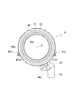
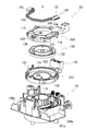
図1は、回転コネクタ装置200の分解斜視図である。図2は、回転コネクタ装置200をステアリングホイールとは反対側から見た平面図であり、スイッチ取付部19に取り付けられるレバースイッチ90を、仮想線で示した図である。
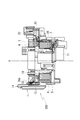
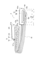
図3は、図2におけるB-B断面図である。
なお、以下においては、図1における上側を上方、下側を下方として説明する。
図3は、図2におけるB-B断面図である。
なお、以下においては、図1における上側を上方、下側を下方として説明する。
図1に示すように、回転コネクタ装置200は、ボディ1と、ボトムカバー2と、ムービングブロック3と、ターミナルブロック4と、接続コード5とを有する。
まず、ボディ1について説明する。
ボディ1は、非導電性の樹脂で形成されており、車体側の不図示のブラケットに固定して取り付けられている。
ボディ1の中央部には、ステアリングホイール(図示せず)に固定されたステアリングシャフト(図示せず)を挿通させる開口15が、ボディ1を軸線Xの軸方向に貫通して設けられており、軸方向から見て、この開口15を挟んだ両側には、スイッチ取付部18、19が設けられている。
ボディ1は、非導電性の樹脂で形成されており、車体側の不図示のブラケットに固定して取り付けられている。
ボディ1の中央部には、ステアリングホイール(図示せず)に固定されたステアリングシャフト(図示せず)を挿通させる開口15が、ボディ1を軸線Xの軸方向に貫通して設けられており、軸方向から見て、この開口15を挟んだ両側には、スイッチ取付部18、19が設けられている。
図2に示すように、ボディ1のスイッチ取付部19には、軸線Xの径方向から、レバースイッチ90が取り付けられるようになっており、開口15を挟んで反対側に位置するスイッチ取付部18にも、軸線Xの径方向から、レバースイッチ(図示せず)が取り付けられるようになっている。
ここで、実施の形態におけるレバースイッチ90には、車両の前照灯のスイッチ、ターンシグナルスイッチ、ワイパースイッチなどが設けられている。
ここで、実施の形態におけるレバースイッチ90には、車両の前照灯のスイッチ、ターンシグナルスイッチ、ワイパースイッチなどが設けられている。
図1に示すように、ボディ1におけるボトムカバー2側の上面には、軸方向から見てリング状の凹部13が形成されている。この凹部13の内周面には、ボトムカバー2と係合するための係合片(図示せず)が、周方向に沿って所定間隔で複数設けられており、ボトムカバー2が図中上側からこの凹部13に取り付けられた際に、係合片の各々が、ボトムカバー2の外壁20の外周面に設けられた係合爪25にスナップ係合して、ボトムカバー2がボディ1に固定されるようになっている。
凹部13の内径側に位置する開口15内には、ステアリングホイール(図示せず)に連結されたロータ10が、軸線X方向に貫通して設けられており、このロータ10は、開口15内で軸線X周りに回転可能に設けられている。
ロータ10は、筒形状を成しており、このロータ10には、係合片11と、径方向外側に膨出した突出部17とが、軸線X周りの周方向で間隔を空けて複数設けられている。
実施の形態では、ロータ10は、後記するムービングブロック3に連結されて、ロータ10とムービングブロック3が軸線X周りに一体に回転するようになっており、ロータ10は、突出部17と係合片11を、それぞれムービングブロック3の切欠部37と係合爪38に係合させて、ムービングブロック3に連結されるようになっている。
ロータ10は、筒形状を成しており、このロータ10には、係合片11と、径方向外側に膨出した突出部17とが、軸線X周りの周方向で間隔を空けて複数設けられている。
実施の形態では、ロータ10は、後記するムービングブロック3に連結されて、ロータ10とムービングブロック3が軸線X周りに一体に回転するようになっており、ロータ10は、突出部17と係合片11を、それぞれムービングブロック3の切欠部37と係合爪38に係合させて、ムービングブロック3に連結されるようになっている。
ロータ10の下部には、ステアリンシャフト(図示せず)に装着されるロータハウジング7が連結されており、ロータ10と一体に回転するロータハウジング7は、ボディ1の下部で回転可能に支持されている。
図1に示すように、ボディ1における凹部13の外径側には、ボトムカバー2のコネクタ部22を支持するコネクタ支持部12が設けられており、開口15を挟んでこのコネクタ支持部12と反対側の位置には、ボディ1を車体側の係合部(図示せず)に係合させて、ボディ1を車体側に固定するためのボディ係合部14が設けられている。
図3に示すように、ロータハウジング7の上側には、軸方向から見てリング状の収容空間Sが形成されており、この収容空間Sでは、ボディ1が外周壁と底壁を構成し、ロータ10が内周壁を構成し、ボトムカバー2が、収容空間Sのボトムカバー2側(図3において上側)の開口を塞ぐ蓋を構成している。
収容空間S内には、車体側とステアリングホイール側間の電気信号等の通電を行うためのフラットケーブル81が、スペーサ8に巻き回された状態で収容されており、フラットケーブル81の一端は、ボトムカバー2のコネクタ部22の端子に接続され、他端は、ロータハウジング7のコネクタ部71(図1参照)に接続されている。
収容空間S内には、車体側とステアリングホイール側間の電気信号等の通電を行うためのフラットケーブル81が、スペーサ8に巻き回された状態で収容されており、フラットケーブル81の一端は、ボトムカバー2のコネクタ部22の端子に接続され、他端は、ロータハウジング7のコネクタ部71(図1参照)に接続されている。
次に、ボトムカバー2について説明する。
図1に示すように、ボトムカバー2は、ボディ1の凹部13に収納された状態でボディ1に取り付けられるようになっており、非導電性の樹脂で形成されている。
ボトムカバー2は、軸方向から見てリング状の円盤部21の中央部に、ロータ10を挿通させるための貫通穴21aを有している。円盤部21における内径側には、貫通穴21aを囲むリング状の内周リブ26が設けられており、外径側には、円盤部21の外周縁を全周に亘って囲む外壁20が設けられている。
これら内周リブ26と外壁20は、ターミナルブロック4側の上方に延出して形成されており、外壁20のほうが、内周リブ26よりも上方まで延びている。
図1に示すように、ボトムカバー2は、ボディ1の凹部13に収納された状態でボディ1に取り付けられるようになっており、非導電性の樹脂で形成されている。
ボトムカバー2は、軸方向から見てリング状の円盤部21の中央部に、ロータ10を挿通させるための貫通穴21aを有している。円盤部21における内径側には、貫通穴21aを囲むリング状の内周リブ26が設けられており、外径側には、円盤部21の外周縁を全周に亘って囲む外壁20が設けられている。
これら内周リブ26と外壁20は、ターミナルブロック4側の上方に延出して形成されており、外壁20のほうが、内周リブ26よりも上方まで延びている。
外壁20には、径方向から見て矩形形状の係合片27が、ターミナルブロック4側の上方に向けて突設して形成されている。係合片27は、軸線X周りの周方向で、間隔を空けて複数設けられており、係合片27の各々には、後記するターミナルブロック4の係合爪47をスナップ係合させるための開口27aが、厚み方向に貫通して設けられている。
外壁20では、貫通穴21aを挟んでコネクタ部22と対向する部位に、コード係合部24が設けられている。コード係合部24は、ターミナルブロック4側の上方に向けて突出して形成されており、軸線X周りの周方向で間隔を空けて3つ設けられている。
これらコード係合部24の間には、前記した係合片27が位置しており、コード係合部24は、係合片27の間に位置する中央爪28aと、係合片27の両側に位置する連携爪28b、28cと、を備えている。中央爪28aと連携爪28b、28cの軸線X方向の高さは、それぞれほぼ同一に形成されており、回転コネクタ装置200が組み立てられた際に、ターミナルブロック4の内周リブ46とほぼ同じ軸線X方向の高さとなるように設定されている。
これらコード係合部24の間には、前記した係合片27が位置しており、コード係合部24は、係合片27の間に位置する中央爪28aと、係合片27の両側に位置する連携爪28b、28cと、を備えている。中央爪28aと連携爪28b、28cの軸線X方向の高さは、それぞれほぼ同一に形成されており、回転コネクタ装置200が組み立てられた際に、ターミナルブロック4の内周リブ46とほぼ同じ軸線X方向の高さとなるように設定されている。
また、中央爪28aは、連携爪28b、28cよりも幅広に形成されている。中央爪28aと連携爪28b、28cでは、ターミナルブロック104側の上端に、径方向外側に突出して先端突起29a、29b、29cが設けられており、これら先端突起29a、29b、29cの下側に、後記する接続コード5のコード部53が係止されるようになっている(図2参照)。
次に、ターミナルブロック4について説明する。
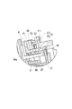
図4は、ターミナルブロック4を説明する図であり、(A)は、ターミナルブロック4をステアリングホイールとは反対側から見た斜視図であり、(B)は、ターミナルブロック4に設けられたコネクタ支持部41の部分を拡大して示す平面図であり、(C)は、(B)におけるA-A断面図である。図5は、ターミナルブロック4をボトムカバー2側から見た平面図である。
図4は、ターミナルブロック4を説明する図であり、(A)は、ターミナルブロック4をステアリングホイールとは反対側から見た斜視図であり、(B)は、ターミナルブロック4に設けられたコネクタ支持部41の部分を拡大して示す平面図であり、(C)は、(B)におけるA-A断面図である。図5は、ターミナルブロック4をボトムカバー2側から見た平面図である。
図4に示すように、ターミナルブロック4は、軸方向から見てリング状の円盤部48の中央部に、ロータ10を挿通させるための貫通穴48aを有している。円盤部48の内径側には、貫通穴48aを囲むリング状の内周リブ46が設けられている。
円盤部48には、前記したボディ1のスイッチ取付部18、19(図1参照)と整合する位置に、円盤部48よりも薄肉のフランジ部40、40が設けられている。
図1に示すように、実施の形態では、フランジ部40、40は、円盤部48におけるスイッチ取付部18、19と整合する部分を、ボトムカバー2側の下方に凹ませて形成されており、フランジ部40、40の軸線X方向の厚みh1は、円盤部48の軸線X方向の厚みhよりも小さくなっている。(h>h1)。
円盤部48には、前記したボディ1のスイッチ取付部18、19(図1参照)と整合する位置に、円盤部48よりも薄肉のフランジ部40、40が設けられている。
図1に示すように、実施の形態では、フランジ部40、40は、円盤部48におけるスイッチ取付部18、19と整合する部分を、ボトムカバー2側の下方に凹ませて形成されており、フランジ部40、40の軸線X方向の厚みh1は、円盤部48の軸線X方向の厚みhよりも小さくなっている。(h>h1)。
このフランジ部40、40の上面40b(図4の(C)参照:ボトムカバー2とは反対側の面)には、後記する接続コード5のコネクタ51、52を支持するためのコネクタ支持部41、41が上方に突出して形成されている。なお、このコネクタ支持部41の構成については、後に詳細に説明する。
図1に示すように、円盤部48における、一方のフランジ部40に隣接する位置には、径方向外側に突出して、コネクタ取付部44が設けられている。
このコネクタ取付部44には、厚み方向に貫通してネジ穴44aが形成されており、ターミナルブロック4は、ネジ穴44aに挿通させたネジ(図示せず)により、ボディ1に対して固定されるようになっている。
また、ターミナルブロック4の円盤部48の外周縁では、径方向外側に突出する係合爪47が、周方向に間隔を空けて複数設けられている。この係合爪47は、ターミナルブロック4とボトムカバー2とが組付けられた際に、ボトムカバー2の外壁20に形成された係合片27の開口27aとスナップ係合して、ターミナルブロック4がボトムカバー2に固定されるようになっている。
このコネクタ取付部44には、厚み方向に貫通してネジ穴44aが形成されており、ターミナルブロック4は、ネジ穴44aに挿通させたネジ(図示せず)により、ボディ1に対して固定されるようになっている。
また、ターミナルブロック4の円盤部48の外周縁では、径方向外側に突出する係合爪47が、周方向に間隔を空けて複数設けられている。この係合爪47は、ターミナルブロック4とボトムカバー2とが組付けられた際に、ボトムカバー2の外壁20に形成された係合片27の開口27aとスナップ係合して、ターミナルブロック4がボトムカバー2に固定されるようになっている。
ターミナルブロック4は、非導電性の樹脂で形成されており、円盤部48の内部には、軸方向から見てリング状の固定電極61、62が、インサート成形により設けられている。
図5に示すように、これら固定電極61、62は、円盤部48のボトムカバー2側の下面に露出して設けられており、固定電極62よりも小径の固定電極61は、固定電極62の内径側に位置している。
固定電極61、62は、ターミナルブロック4内に埋め込まれた配線(図示せず)を介して、コネクタ部45の端子に接続されており、このコネクタ部45に車体側のコネクタが接続されると、車体側から固定電極61、62に電力が供給されるようになっている。
図5に示すように、これら固定電極61、62は、円盤部48のボトムカバー2側の下面に露出して設けられており、固定電極62よりも小径の固定電極61は、固定電極62の内径側に位置している。
固定電極61、62は、ターミナルブロック4内に埋め込まれた配線(図示せず)を介して、コネクタ部45の端子に接続されており、このコネクタ部45に車体側のコネクタが接続されると、車体側から固定電極61、62に電力が供給されるようになっている。
図1に示すように、ムービングブロック3は、軸方向から見てリング状の円盤部31の中央部に、ロータ10を挿通させるための貫通穴30aを有している。円盤部31の内径側には、貫通穴30aを囲むリング状の内周リブ36が形成されており、円盤部31の外周縁には、全周に亘って外周リブ30が形成されている。
内周リブ36と外周リブ30は、それぞれターミナルブロック4側の上方に延出して形成されており、内周リブ36のほうが、外周リブ30よりも上方に延びている。
内周リブ36と外周リブ30は、それぞれターミナルブロック4側の上方に延出して形成されており、内周リブ36のほうが、外周リブ30よりも上方に延びている。
内周リブ36では、貫通穴30aを挟んで対向する位置に、切欠部37が設けられており、この切欠部37には、ロータ10とムービングブロック3とを連結した際に、ロータ10の突出部17が軸方向から嵌合して、ロータ10とムービングブロック3とが軸線X周りの周方向で相対回転不能に連結されるようになっている。
また、内周リブ36の貫通穴30a側の面には、径方向内側に突出して係合爪38が設けられている。この係合爪38は、軸線X周りの周方向で間隔を空けて複数設けられており、ロータ10とムービングブロック3とを連結した際に、係合爪38が、ロータ10側の係合片11の開口にスナップ係合して、ムービングブロック3のロータ10からの脱落が阻止されるようになっている。
また、内周リブ36の貫通穴30a側の面には、径方向内側に突出して係合爪38が設けられている。この係合爪38は、軸線X周りの周方向で間隔を空けて複数設けられており、ロータ10とムービングブロック3とを連結した際に、係合爪38が、ロータ10側の係合片11の開口にスナップ係合して、ムービングブロック3のロータ10からの脱落が阻止されるようになっている。
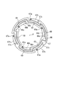
図6は、ムービングブロック3に埋め込まれる可動電極66、67を、ターミナルブロック4側から見た平面図である。
非導電性の樹脂で形成されたムービングブロック3の円盤部31(図1参照)の内部には、軸方向から見て略リング状の可動電極66、67が、インサート成形により埋め込まれている。
可動電極66は、可動電極67よりも小径で形成されており、円盤部31では、内径側に可動電極66が、外径側に可動電極67が、それぞれ位置している。
ここで、これら可動電極66、67は、インサート成形により円盤部31に埋め込まれる前の段階では、複数の幅狭部69で繋がれて1枚のリング状の円盤に形成されており、インサート成形される際に、幅狭部69が切断されることで、内径側の可動電極66と外径側の可動電極67との2つに分割されて、2系統の可動電極が、円盤部31内に設けられるようになっている。
非導電性の樹脂で形成されたムービングブロック3の円盤部31(図1参照)の内部には、軸方向から見て略リング状の可動電極66、67が、インサート成形により埋め込まれている。
可動電極66は、可動電極67よりも小径で形成されており、円盤部31では、内径側に可動電極66が、外径側に可動電極67が、それぞれ位置している。
ここで、これら可動電極66、67は、インサート成形により円盤部31に埋め込まれる前の段階では、複数の幅狭部69で繋がれて1枚のリング状の円盤に形成されており、インサート成形される際に、幅狭部69が切断されることで、内径側の可動電極66と外径側の可動電極67との2つに分割されて、2系統の可動電極が、円盤部31内に設けられるようになっている。
可動電極66、67では、先端に接点66a、67aが形成された腕部66b、67bが、周方向に沿って設けられている。
実施の形態では、これら腕部66b、67bは、軸線X周りの周方向に間隔を空けて複数設けられており、これら腕部66b、67bの先端(接点66a、67a)側がターミナルブロック4側の上方に位置するように、その基端66c、67c側が折り曲げられている。
実施の形態では、これら腕部66b、67bは、軸線X周りの周方向に間隔を空けて複数設けられており、これら腕部66b、67bの先端(接点66a、67a)側がターミナルブロック4側の上方に位置するように、その基端66c、67c側が折り曲げられている。
そのため、ムービングブロック3がボトムカバー2とターミナルブロック4の間に配置された際に、可動電極66、67の接点66a、67aが、軸線Xの軸方向からターミナルブロック4の固定電極61、62に接触し、腕部66b、67bの付勢力により、可動電極66、67の接点66a、67aと固定電極61、62との接触状態が保持されるようになっている。
ここで、ロータ10と一体にムービングブロック3が軸線X周りに回転すると、可動電極66、67の接点66a、67aもまた軸線X周りに回転することになる。
前記したターミナルブロック4の固定電極61、62は、ムービングブロック3が軸線X周りに回転するときの接点66a、67aが描く軌跡に沿って円形を成しているので、ステアリングホイールの操作に連動して、ムービングブロック3がターミナルブロック4に対して相対回転する際に、可動電極66、67と固定電極61、62との接触状態が維持されるようになっている。
前記したターミナルブロック4の固定電極61、62は、ムービングブロック3が軸線X周りに回転するときの接点66a、67aが描く軌跡に沿って円形を成しているので、ステアリングホイールの操作に連動して、ムービングブロック3がターミナルブロック4に対して相対回転する際に、可動電極66、67と固定電極61、62との接触状態が維持されるようになっている。
よって、可動電極66、67が図示しない配線を介してステアリングヒータに接続されている場合には、車体側から固定電極61、62に供給された電力が、可動電極66、67を介して途切れることなくステアリングヒータ側に給電されるようになっている。
次に、ターミナルブロック4に設けられたコネクタ支持部41、41について説明する。なお、ターミナルブロック4においてコネクタ支持部41、41は、貫通穴48aを挟んで左右対称となる位置に設けられている。
そのため、以下の説明においては、図4の(A)において右側に位置するコネクタ支持部41について説明をし、左側に位置するコネクタ支持部41については、その説明を省略する。
そのため、以下の説明においては、図4の(A)において右側に位置するコネクタ支持部41について説明をし、左側に位置するコネクタ支持部41については、その説明を省略する。
図4に示すように、コネクタ支持部41は、内径側支持部411と、外径側支持部412とを備えており、これら内径側支持部411と外径側支持部412は、ターミナルブロック4のフランジ部40から、このフランジ部40に対して直交する方向(図4の(C)において上側)に延出して形成されている。
内径側支持部411は、フランジ部40の周方向における中央寄りの位置に設けられており、外径側支持部412は、フランジ部40の周方向における一方側に近接して設けられている。
軸方向から見て、内径側支持部411と外径側支持部412は、同一直線Ln上に位置しており、外径側支持部412は、その一部が、フランジ部40の外周縁40aから径方向外側に突出して設けられている(図5参照)。
内径側支持部411と外径側支持部412は、側縁部411a、412aと、この側縁部411a、412aの両側から、側縁部411a、412aの直交方向に延びる支持部411b、412bと、を備えており、軸方向から見てコ字形状に形成されている。
軸方向から見て、内径側支持部411と外径側支持部412は、同一直線Ln上に位置しており、外径側支持部412は、その一部が、フランジ部40の外周縁40aから径方向外側に突出して設けられている(図5参照)。
内径側支持部411と外径側支持部412は、側縁部411a、412aと、この側縁部411a、412aの両側から、側縁部411a、412aの直交方向に延びる支持部411b、412bと、を備えており、軸方向から見てコ字形状に形成されている。
内径側支持部411の側縁部411aにおける支持部411b、411bの間には、支持部411bと同方向に突出して爪411cが設けられており、外径側支持部412の側縁部412aにおける支持部412b、412bの間にも、支持部412bと同方向に突出して爪412cが設けられている。
実施の形態では、これら爪411c、412cは、内径側支持部411と外径側支持部412にコネクタ51を取り付けるときのガイド、および抜け止めとして機能するようになっている。
そのため、爪411c、412cの上面は、爪411c、412cをガイドとして機能させるために、爪411c、412cの高さhaが側縁部411a、412aから離れるにつれて低くなる向きに傾斜している。また、爪411c、412cの下面は、爪411c、412cを抜け止めとして機能させるために、フランジ部40に対して平行となっている。
そのため、爪411c、412cの上面は、爪411c、412cをガイドとして機能させるために、爪411c、412cの高さhaが側縁部411a、412aから離れるにつれて低くなる向きに傾斜している。また、爪411c、412cの下面は、爪411c、412cを抜け止めとして機能させるために、フランジ部40に対して平行となっている。
図7は、図2におけるA-A断面図であって、コネクタ支持部41周りの構成を説明する図である。
図7に示すように、ターミナルブロック4の下面には、円盤部48に埋め込まれた固定電極61、62が露出しており、爪411c(図4参照)を形成するための金型を、下側から抜くことが困難となっている。そのため、内径側支持部411の外径側の支持部411bには、横方向に金型を抜くための型抜き穴411dが形成されている(図4の(B)参照)。
また、外径側支持部412は、爪412cが設けられた側縁部412a側が、フランジ部40の外周縁40aよりも径方向外側に突出しているので、爪412cを形成するための金型を、下側から抜くことができるようになっている。そのため、外径側支持部412では、支持部412bと支持部412bの間の下部には、下方向に金型を抜くための型抜き穴412dが形成されている(図4の(C)、図5参照)。
図7に示すように、ターミナルブロック4の下面には、円盤部48に埋め込まれた固定電極61、62が露出しており、爪411c(図4参照)を形成するための金型を、下側から抜くことが困難となっている。そのため、内径側支持部411の外径側の支持部411bには、横方向に金型を抜くための型抜き穴411dが形成されている(図4の(B)参照)。
また、外径側支持部412は、爪412cが設けられた側縁部412a側が、フランジ部40の外周縁40aよりも径方向外側に突出しているので、爪412cを形成するための金型を、下側から抜くことができるようになっている。そのため、外径側支持部412では、支持部412bと支持部412bの間の下部には、下方向に金型を抜くための型抜き穴412dが形成されている(図4の(C)、図5参照)。
次に、接続コード5とその取り付け状態について説明する。
図8は、接続コード5の斜視図である。
図8は、接続コード5の斜視図である。
図8に示すように、接続コード5は、レバースイッチ90側のコネクタ端子91(図2参照)が接続されるコネクタ51、52と、これらを互いに接続するコード部53と、から構成される。
図8および図4の(C)に示すように、コネクタ51、52は、直方体形状のコネクタ本体部55、56と、コネクタ本体部55、56を支持する薄板状の被支持部57、58とから構成されており、被支持部57、58においてコネクタ本体部55、56は、当該被支持部57、58の直交方向に突出して設けられている。
図8および図4の(C)に示すように、コネクタ51、52は、直方体形状のコネクタ本体部55、56と、コネクタ本体部55、56を支持する薄板状の被支持部57、58とから構成されており、被支持部57、58においてコネクタ本体部55、56は、当該被支持部57、58の直交方向に突出して設けられている。
コネクタ本体部55、56内には、レバースイッチ90側のコネクタ端子91(図2参照)が挿入される端子穴55a、56aが設けられており、端子穴55a、56aは、コネクタ本体部55、56の幅方向で、間隔を空けて複数設けられている。
被支持部57、58は、正面視において矩形形状を有しており、コネクタ本体部55、56は、被支持部57、58の高さ方向における下側の側縁57a、58aに沿って設けられている。
被支持部57、58の幅W1は、コネクタ本体部55、56の幅W2よりも大きくなっており、被支持部57、58におけるコネクタ本体部55、56から側方に突出する部分は、前記したコネクタ支持部41の内径側支持部411と外径側支持部412で支持される被支持部571、581となっている。
被支持部57、58における幅方向の両側には、幅方向に突出して係合突起571a、581aが設けられており、係合突起571a、581aは、コネクタ51、52のコネクタ支持部41からの脱落を防止するための抜け止めとして機能するようになっている。
被支持部57、58は、正面視において矩形形状を有しており、コネクタ本体部55、56は、被支持部57、58の高さ方向における下側の側縁57a、58aに沿って設けられている。
被支持部57、58の幅W1は、コネクタ本体部55、56の幅W2よりも大きくなっており、被支持部57、58におけるコネクタ本体部55、56から側方に突出する部分は、前記したコネクタ支持部41の内径側支持部411と外径側支持部412で支持される被支持部571、581となっている。
被支持部57、58における幅方向の両側には、幅方向に突出して係合突起571a、581aが設けられており、係合突起571a、581aは、コネクタ51、52のコネクタ支持部41からの脱落を防止するための抜け止めとして機能するようになっている。
以下、コネクタ51、52のコネクタ支持部41への取り付けを、コネクタ51の場合を例に挙げて説明する。
図4に示すように、コネクタ51は、幅方向における両側の被支持部571、571を、内径側支持部411と外径側支持部412の支持部411b、411bの間に挿入して、コネクタ支持部41に取り付けられるようになっている。
図4に示すように、コネクタ51は、幅方向における両側の被支持部571、571を、内径側支持部411と外径側支持部412の支持部411b、411bの間に挿入して、コネクタ支持部41に取り付けられるようになっている。
コネクタ51をフランジ部40側の下方に押し込むと、コネクタ51は、被支持部571の係合突起571aを弾性変形させながら、フランジ部40に当接する位置まで移動する。そうすると、コネクタ51の係合突起571aと、コネクタ支持部41の爪411c、412cとが、コネクタ51の幅方向で重なる位置に配置されるので、コネクタ51は、コネクタ支持部41からの脱落が阻止された状態で、コネクタ支持部41に保持されることになる。
ここで、コネクタ51の被支持部571と、内径側支持部411および外径側支持部412との間に僅かな隙間が設けられているので、コネクタ支持部41においてコネクタ51は、若干の遊びを持って支持されることになる。よって、コネクタ51にレバースイッチ90を接続する際に、コネクタ51とレバースイッチ90との間に僅かな位置ずれが生じていてもコネクタ51とレバースイッチ90とを確実に接続できるようになっている。
また、被支持部571が、コネクタ本体部55の幅方向に突出して設けられており、この被支持部571のコネクタ支持部41における支持幅W(図4の(C)参照)が確保されているので、コネクタ51は、十分な支持強度を持って、コネクタ支持部41に支持されるようになっている。
また、被支持部571が、コネクタ本体部55の幅方向に突出して設けられており、この被支持部571のコネクタ支持部41における支持幅W(図4の(C)参照)が確保されているので、コネクタ51は、十分な支持強度を持って、コネクタ支持部41に支持されるようになっている。
ここで、実施の形態にかかる回転コネクタ装置200の各部材(ボトムカバー2、ターミナルブロック4、ムービングブロック3)と、従来例にかかる回転コネクタ装置201の各部材(ボトムカバー102、ターミナルブロック104、ムービングブロック103)との相違点を説明する。
回転コネクタ装置200の各部材(ボトムカバー2、ターミナルブロック4、ムービングブロック3)では、ステアリングシャフトの大径化に対応するために、各円盤部21、48、31の貫通孔21a、48a、30aの内径が、従来の回転コネクタ装置201における対応する円盤部121、148、131の貫通孔125、149、135の内径よりも大きくなっている。
さらに、回転コネクタ装置200のボトムカバー2では、従来の回転コネクタ装置201のボトムカバー102で外側周壁120の内側に設けられていた内側周壁122に相当するものが削除されているので、ムービングブロック3の外径が、ボトムカバー2の外壁20よりも僅かに小さい外径まで広げられている。
そのため、ムービングブロック3の円盤部31の径方向の幅W3(図1参照)は、従の回転コネクタ装置201におけるムービングブロック103の円盤部131の径方向の幅と同になっており、円盤部31に可動電極を埋め込むのに必要な径方向の幅が確保されている。
そのため、ムービングブロック3の円盤部31の径方向の幅W3(図1参照)は、従の回転コネクタ装置201におけるムービングブロック103の円盤部131の径方向の幅と同になっており、円盤部31に可動電極を埋め込むのに必要な径方向の幅が確保されている。
そして、ボトムカバー2の外壁20は、従来の回転コネクタ装置201のボトムカバー102における外側周壁120と同じ外径であるので、ムービングブロック3の円盤部31の外径を、ボトムカバー2の外壁20よりも僅かに小さい外径まで広げても、ボトムカバー2とターミナルブロック4における円盤部21、48の外径は、従来の回転コネクタ装置201における対応する円盤部121、148の外径と同じになっている。
このように、実施の形態にかかる回転コネクタ装置200では、従来の回転コネクタ装置201のボトムカバー102に設けられていた内側周壁122に相当するものを削除したので、ムービングブロック3の外径が、外壁20よりも僅かに小さい外径まで拡大可能とされている。
そのため、回転コネクタ装置200の各部材(ボトムカバー2、ターミナルブロック4、ムービングブロック3)の各円盤部21、48、31の貫通孔21a、48a、30aの内径を拡大しても、ボトムカバー2とターミナルブロック4における円盤部21、48の外径を大径化させることなく、ムービングブロック3において、可動電極を埋め込むための径方向の幅W3を確保できるようになっている。
そのため、回転コネクタ装置200の各部材(ボトムカバー2、ターミナルブロック4、ムービングブロック3)の各円盤部21、48、31の貫通孔21a、48a、30aの内径を拡大しても、ボトムカバー2とターミナルブロック4における円盤部21、48の外径を大径化させることなく、ムービングブロック3において、可動電極を埋め込むための径方向の幅W3を確保できるようになっている。
実施形態は以上のように構成され、ステアリングシャフト(図示せず)と一体に回転するムービングブロック3と、車体側に固定されたボディ1で支持された固定部材(ターミナルブロック4、ボトムカバー2)とが、同一の軸線X上で互いに相対回転可能に設けられており、
ムービングブロック3とターミナルブロック4とが、ターミナルブロック4に設けた固定電極61、62(導電リング)と、ムービングブロック3に設けられて固定電極61、62を摺動する接点66a、67aを有する可動電極66、67(摺動接触子)とからなるスリップリング機構を介して電気的に接続され、
ボディ1における固定部材(ターミナルブロック4、ボトムカバー2)の径方向外側に、レバースイッチ90のスイッチ取付部18、19が設けられた回転コネクタ装置200において、
レバースイッチ90に接続されるコネクタ51、52の保持部であるコネクタ支持部41を、軸線Xの軸方向でターミナルブロック4におけるムービングブロック3とは反対側に設けた構成とした。
ムービングブロック3とターミナルブロック4とが、ターミナルブロック4に設けた固定電極61、62(導電リング)と、ムービングブロック3に設けられて固定電極61、62を摺動する接点66a、67aを有する可動電極66、67(摺動接触子)とからなるスリップリング機構を介して電気的に接続され、
ボディ1における固定部材(ターミナルブロック4、ボトムカバー2)の径方向外側に、レバースイッチ90のスイッチ取付部18、19が設けられた回転コネクタ装置200において、
レバースイッチ90に接続されるコネクタ51、52の保持部であるコネクタ支持部41を、軸線Xの軸方向でターミナルブロック4におけるムービングブロック3とは反対側に設けた構成とした。
このように構成すると、ムービングブロック3の径方向外側にコネクタ支持部41が位置していないので、ムービングブロック3の外径をターミナルブロック4の外径まで広げることができる。よって、スリップリング機構に必要な径方向の幅(可動電極66、67を配置するのに必要な幅)をムービングブロック3において確保しつつ、ステアリングシャフトの大径化に対応できる。
また、レバースイッチ90のスイッチ取付部18、19は、軸方向から見て、ターミナルブロック4の径方向外側に設けられており、ムービングブロック3の外径をターミナルブロック4の外径まで広げてもレバースイッチ90のレイアウトに影響が及ぶことがない。
よって、スリップリング機構を備える回転コネクタ装置において、レバースイッチ90のレイアウトに影響を与えずに、ステアリングシャフトの大径化に対応させることができる。
また、レバースイッチ90のスイッチ取付部18、19は、軸方向から見て、ターミナルブロック4の径方向外側に設けられており、ムービングブロック3の外径をターミナルブロック4の外径まで広げてもレバースイッチ90のレイアウトに影響が及ぶことがない。
よって、スリップリング機構を備える回転コネクタ装置において、レバースイッチ90のレイアウトに影響を与えずに、ステアリングシャフトの大径化に対応させることができる。
固定部材は、ボトムカバー2と、このボトムカバー2に軸線Xの軸方向から組み付けられるターミナルブロック4とから構成されていると共に、ボトムカバー2のリング状の円盤部21と、ターミナルブロック4のリング状の円盤部48とが軸線Xの軸方向で間隔をあけて配置されており、
ムービングブロック3は、軸線Xの軸方向におけるこれら円盤部21、48の間に位置しており、
ボトムカバー2は、ムービングブロック3の外周を所定間隔で囲むと共に、ターミナルブロック4の円盤部48の外周に接触する外壁20を有しており、
ターミナルブロック4におけるコネクタ支持部41が設けられる部位であるフランジ部40の軸方向の厚みh1を、他の部位の厚みhよりも薄くした構成とした。
ムービングブロック3は、軸線Xの軸方向におけるこれら円盤部21、48の間に位置しており、
ボトムカバー2は、ムービングブロック3の外周を所定間隔で囲むと共に、ターミナルブロック4の円盤部48の外周に接触する外壁20を有しており、
ターミナルブロック4におけるコネクタ支持部41が設けられる部位であるフランジ部40の軸方向の厚みh1を、他の部位の厚みhよりも薄くした構成とした。
従来の回転コネクタ装置では、ボトムカバー102の外側周壁120と内側周壁122との上部にコネクタ支持部123、124が設けられていたが(図9参照)、実施の形態にかかる回転コネクタ装置200では、ボトムカバー2の外壁20の上部に取り付けられるターミナルブロック4に、コネクタ支持部41が設けられている。
そのため、軸線X方向におけるコネクタ支持部41の位置が、従来の回転コネクタ装置201の場合に比べて上側にズレてしまうことになるが、コネクタ支持部41が設けられるフランジ部40の厚みを薄くすることで、コネクタ支持部41の軸方向の位置ズレが抑えられるようになっている。
そのため、従来の回転コネクタ装置201におけるコネクタ取付部の位置や、このコネクタ取付部に取り付けられるレバースイッチ側のコネクタの位置を、軸線Xの軸方向で大きく変更することなく、レバースイッチを、実施の形態にかかる回転コネクタ装置200にそのまま取り付けることができる
そのため、軸線X方向におけるコネクタ支持部41の位置が、従来の回転コネクタ装置201の場合に比べて上側にズレてしまうことになるが、コネクタ支持部41が設けられるフランジ部40の厚みを薄くすることで、コネクタ支持部41の軸方向の位置ズレが抑えられるようになっている。
そのため、従来の回転コネクタ装置201におけるコネクタ取付部の位置や、このコネクタ取付部に取り付けられるレバースイッチ側のコネクタの位置を、軸線Xの軸方向で大きく変更することなく、レバースイッチを、実施の形態にかかる回転コネクタ装置200にそのまま取り付けることができる
特に、実施の形態にかかる回転コネクタ装置200では、コネクタ支持部41を、ターミナルブロック4におけるボトムカバー2とは反対側の面に設けた構成とすることで、従来の回転コネクタ装置201においてコネクタ支持部123、124を支持するために設けていた内側周壁122を削除できるようにした。
そのため、ムービングブロック3の外径を、回転コネクタ装置200の外壁20(従来の回転コネクタ装置201における外側周壁120に相当)よりも僅かに小さい外径まで広げて、円板部21の径方向の幅を確保できるようになっている。
この場合、ステアリングシャフトの大径化に合わせてムービングブロック3の貫通穴21aを大径化しても、ボトムカバー2(外壁40)を大径化する必要がないので、ボトムカバー2の径方向外側に位置するスイッチ取付部18、19の位置を、ステアリングシャフトの大径化に際して、変更する必要がない。
また、ボトムカバー2の外壁を大径化する必要がないので、ボトムカバー2に組み付けられるターミナルブロック4(円盤部48)の外径も、ステアリングシャフトの大径化に際して変更する(大径化する)必要がない。
よって、回転コネクタ装置200が組み付けられるステアリング装置(図示せず)側に、大きな設計変更が必要になるなどの影響が及ぶことが好適に防止されることになる。
そのため、ムービングブロック3の外径を、回転コネクタ装置200の外壁20(従来の回転コネクタ装置201における外側周壁120に相当)よりも僅かに小さい外径まで広げて、円板部21の径方向の幅を確保できるようになっている。
この場合、ステアリングシャフトの大径化に合わせてムービングブロック3の貫通穴21aを大径化しても、ボトムカバー2(外壁40)を大径化する必要がないので、ボトムカバー2の径方向外側に位置するスイッチ取付部18、19の位置を、ステアリングシャフトの大径化に際して、変更する必要がない。
また、ボトムカバー2の外壁を大径化する必要がないので、ボトムカバー2に組み付けられるターミナルブロック4(円盤部48)の外径も、ステアリングシャフトの大径化に際して変更する(大径化する)必要がない。
よって、回転コネクタ装置200が組み付けられるステアリング装置(図示せず)側に、大きな設計変更が必要になるなどの影響が及ぶことが好適に防止されることになる。
レバースイッチに接続される接続コード5のコネクタ51、52は、コネクタ支持部41に取り付けられた状態で、軸線Xの直交方向に突出するコネクタ本体部55、56と、このコネクタ本体部55、56の幅方向における両側から、幅方向に突出する板状の被支持部571、571、581、581とを備えており、
コネクタ支持部41は、コネクタ本体部55、56の幅方向における一方の被支持部571、581を、幅方向の全長に亘って支持する内径側支持部411と、他方の被支持部571、581を、幅方向の全長に亘って支持する外径側支持部412と、を備える構成とした。
コネクタ支持部41は、コネクタ本体部55、56の幅方向における一方の被支持部571、581を、幅方向の全長に亘って支持する内径側支持部411と、他方の被支持部571、581を、幅方向の全長に亘って支持する外径側支持部412と、を備える構成とした。
このように構成すると、コネクタ51、52の両側に設けられた被支持部571、582における所定の支持幅W(図4の(C)参照)の範囲が、内径側支持部411と外径側支持部412で支持されるので、コネクタ51、52の支持強度を確保することができる。
特に、内径側支持部411と外径側支持部412が、軸方向から見た断面が略コ字形状となっており、板状の被支持部571、581の厚み方向の両面が、支持部411b、412bに挟み込まれた状態で支持されるようにしたので、コネクタ51、52が十分な支持強度で支持されと共に、コネクタ51、52の被支持部571、581のコネクタ支持部41への取付を容易に行えることになる。
コネクタ51、52の被支持部571、581には、幅方向における外側に突出する係合突起571a、581aが設けられており、内径側支持部411と外径側支持部412の側縁部411a、412aには、係合突起571a、581aに係止させる爪411c、412cが、被支持部571、581側に突出して設けられており、
係合突起571a、581aと、爪411c、412cは、軸線Xの軸方向から見て互いに重なる突出長さに形成されている構成とした。
係合突起571a、581aと、爪411c、412cは、軸線Xの軸方向から見て互いに重なる突出長さに形成されている構成とした。
このように構成すると、コネクタ51、52の被支持部571、581の内径側支持部411と外径側支持部412からの脱落が、係合突起571a、581aと爪411c、412cにより阻止されるので、コネクタ51、52を、それぞれ対応するコネクタ支持部41、41で確実に支持させることができる。
ターミナルブロック4におけるフランジ部40、40では、コネクタ51、52のコネクタ本体部55、56と、被支持部57、58が、フランジ部40、40の上面40b、40b(図4の(C)参照)に接して設けられており、このフランジ部40、40の上面40b、40bは、軸線Xに直交する平坦面となっている構成とした。
従来の回転コネクタ装置では、ボトムカバー102の外側周壁120と内側周壁122との上部に設けたコネクタ支持部123、124に、コネクタ151、152を支持させる構成となっていたので、コネクタ本体部55から下側(ボトムカバー側)に突出して被支持部154(図9参照)が設けられており、この被支持部154によりコネクタ151、152の支持強度を確保していた。
実施の形態の回転コネクタ装置では、ボトムカバー2の外壁20の上部に取り付けられるターミナルブロック4に、コネクタ支持部41が設けられており、コネクタ支持部41の軸方向の位置ズレを抑える必要があるので、従来回転コネクタ装置の場合の被支持部154を設けることが困難であった。
そのため、上記のように構成することで、コネクタ支持部41で支持されるコネクタ51、52の支持強度を確保しつつ、コネクタ51、52の軸線Xの軸方向の位置ズレを抑えることができるので、従来の回転コネクタ装置201におけるコネクタの取付部106a、106bの位置や、この取付部106a、106bに取り付けられるレバースイッチ側のコネクタの位置を、軸線Xの軸方向で大きく変更することなく、レバースイッチを、実施の形態にかかる回転コネクタ装置200にそのまま取り付けることができる。
実施の形態の回転コネクタ装置では、ボトムカバー2の外壁20の上部に取り付けられるターミナルブロック4に、コネクタ支持部41が設けられており、コネクタ支持部41の軸方向の位置ズレを抑える必要があるので、従来回転コネクタ装置の場合の被支持部154を設けることが困難であった。
そのため、上記のように構成することで、コネクタ支持部41で支持されるコネクタ51、52の支持強度を確保しつつ、コネクタ51、52の軸線Xの軸方向の位置ズレを抑えることができるので、従来の回転コネクタ装置201におけるコネクタの取付部106a、106bの位置や、この取付部106a、106bに取り付けられるレバースイッチ側のコネクタの位置を、軸線Xの軸方向で大きく変更することなく、レバースイッチを、実施の形態にかかる回転コネクタ装置200にそのまま取り付けることができる。
なお、本発明は上記の実施形態に限定されるものではなく、その技術的思想の範囲内でなしうるさまざまな変更、改良が含まれる。
例えば、本実施形態で可動電極が固定電極に接する接点は、図8に示すような内周側と外周側において3か所ずつとは限らない。例えば、内周側に4か所、外周側に5か所設けることもできる。
また、本実施形態では、被支持部57、58と平行な方向に爪41c、41d、43c、43dを出していたが、爪41c、41d、43c、43dを被支持部57、58を横切る方向に出してもよい。
例えば、本実施形態で可動電極が固定電極に接する接点は、図8に示すような内周側と外周側において3か所ずつとは限らない。例えば、内周側に4か所、外周側に5か所設けることもできる。
また、本実施形態では、被支持部57、58と平行な方向に爪41c、41d、43c、43dを出していたが、爪41c、41d、43c、43dを被支持部57、58を横切る方向に出してもよい。
さらに、上記した実施の形態では、ターミナルブロック4側に導電リング(固定電極61、62)を設け、ムービングブロック3側に導電リングを摺動する摺動接触子(可動電極66、67)を設けた構成のスリップリング機構の場合を例に挙げて説明をした。
実施の形態にかかる回転コネクタ装置において、ターミナルブロック4側に摺動接触子を設けると共に、ムービングブロック3側に導電リングを設けて、ステアリングホイールの操作に連動して、導電リングが可動電極として回転する構成のスリップリング機構としても良い。
実施の形態にかかる回転コネクタ装置において、ターミナルブロック4側に摺動接触子を設けると共に、ムービングブロック3側に導電リングを設けて、ステアリングホイールの操作に連動して、導電リングが可動電極として回転する構成のスリップリング機構としても良い。
1 ボディ
2 ボトムカバー
3 ムービングブロック
4 ターミナルブロック
5 接続コード
7 ロータハウジング
8 スペーサ
10 ロータ
11 係合片
12 コネクタ支持部
13 凹部
14 ボディ係合部
15 開口
17 突出部
18、19 スイッチ取付部
20 外壁
21 円盤部
21a 貫通穴
22 コネクタ部
24 コード係合部
25 係合爪
26 内周リブ
27 係合片
27a 開口
28a 中央爪
28b 連携爪
30 外周リブ
30a 貫通穴
31 円盤部
36 内周リブ
37 切欠部
38 係合爪
40 フランジ部
40a 外周縁
40b 上面
41 コネクタ支持部
41c 爪
44 コネクタ取付部
46 内周リブ
47 係合爪
48 円盤部
48a 貫通穴
51、52 コネクタ
53 コード部
55、56 コネクタ本体部
55a、56a 端子穴
57、58 被支持部
57a、58a 側縁
61、62 固定電極
66、67 可動電極
66a、67a 接点
66b、67b 腕部
66c、67c 基端
71 コネクタ部
81 フラットケーブル
90 レバースイッチ
91 コネクタ端子
200 回転コネクタ装置
411 内径側支持部
412 外径側支持部
571、581 被支持部
571a、581a 係合突起
X 軸線
2 ボトムカバー
3 ムービングブロック
4 ターミナルブロック
5 接続コード
7 ロータハウジング
8 スペーサ
10 ロータ
11 係合片
12 コネクタ支持部
13 凹部
14 ボディ係合部
15 開口
17 突出部
18、19 スイッチ取付部
20 外壁
21 円盤部
21a 貫通穴
22 コネクタ部
24 コード係合部
25 係合爪
26 内周リブ
27 係合片
27a 開口
28a 中央爪
28b 連携爪
30 外周リブ
30a 貫通穴
31 円盤部
36 内周リブ
37 切欠部
38 係合爪
40 フランジ部
40a 外周縁
40b 上面
41 コネクタ支持部
41c 爪
44 コネクタ取付部
46 内周リブ
47 係合爪
48 円盤部
48a 貫通穴
51、52 コネクタ
53 コード部
55、56 コネクタ本体部
55a、56a 端子穴
57、58 被支持部
57a、58a 側縁
61、62 固定電極
66、67 可動電極
66a、67a 接点
66b、67b 腕部
66c、67c 基端
71 コネクタ部
81 フラットケーブル
90 レバースイッチ
91 コネクタ端子
200 回転コネクタ装置
411 内径側支持部
412 外径側支持部
571、581 被支持部
571a、581a 係合突起
X 軸線
Claims (5)
- ステアリングシャフトと一体に回転する回転部材と、車体側に固定されたボディで支持された固定部材とが、同軸上で相対回転可能に設けられており、
前記回転部材と前記固定部材とが、前記回転部材と前記固定部材のうちの一方に設けた導電リングと、他方に設けられて前記導電リングを摺動する摺動接触子とからなるスリップリング機構を介して電気的に接続され、
前記ボディにおける前記回転部材と前記固定部材の径方向外側に、レバースイッチの取付部が設けられた回転コネクタ装置において、
前記レバースイッチに接続されるコネクタの支持部を、前記固定部材における前記回転部材とは反対側に設けたことを特徴とする回転コネクタ装置とした。 - 前記固定部材は、前記回転部材の回転軸の軸方向で間隔をあけて配置された第1の固定部材と第2の固定部材とから構成され、
前記回転部材は、前記軸方向における前記第1の固定部材と前記第2の固定部材の間に位置しており、
前記第2の固定部材は、前記回転部材の外周を所定間隔で囲むと共に、前記第1の固定部材の外周に接触する周壁を有しており、
前記第1の固定部材における前記支持部が設けられた部位の前記軸方向の厚みを、他の部位よりも薄くしたことを特徴とする請求項1に記載の回転コネクタ装置。 - 前記レバースイッチに接続されるコネクタは、
前記回転軸の直交方向に突出するコネクタ本体部と、
前記コネクタ本体部の幅方向における両側から、前記幅方向に突出する板状の支持リブと、を備えており、
前記コネクタの支持部は、
前記幅方向における一方の支持リブを、前記幅方向の全長に亘って支持する第1の支持部と、
他方の支持リブを、前記幅方向の全長に亘って支持する第2の支持部と、を備えることを特徴とする請求項2に記載の回転コネクタ装置。 - 前記一方の支持リブと前記他方の支持リブには、前記幅方向における外側に突出する突起が設けられており、前記第1の支持部と前記第2の支持部には、前記突起を係止させる係止部が、前記一方の支持リブと前記他方の支持リブ側に突出して設けられており、
前記突起と前記係止部は、前記軸方向から見て互いに重なる突出長さに形成されていることを特徴とする請求項3に記載の回転コネクタ装置。 - 前記第1の固定部材における前記コネクタの保持部が設けられる部位では、前記コネクタ本体部と前記支持リブが、前記回転部材とは反対側の面に接して設けられていることを特徴とする請求項4に記載の回転コネクタ装置。
Applications Claiming Priority (2)
| Application Number | Priority Date | Filing Date | Title |
|---|---|---|---|
| JP2012-159860 | 2012-07-18 | ||
| JP2012159860A JP5937908B2 (ja) | 2012-07-18 | 2012-07-18 | 回転コネクタ装置 |
Publications (1)
| Publication Number | Publication Date |
|---|---|
| WO2014013904A1 true WO2014013904A1 (ja) | 2014-01-23 |
Family
ID=49948734
Family Applications (1)
| Application Number | Title | Priority Date | Filing Date |
|---|---|---|---|
| PCT/JP2013/068691 Ceased WO2014013904A1 (ja) | 2012-07-18 | 2013-07-08 | 回転コネクタ装置 |
Country Status (2)
| Country | Link |
|---|---|
| JP (1) | JP5937908B2 (ja) |
| WO (1) | WO2014013904A1 (ja) |
Cited By (1)
| Publication number | Priority date | Publication date | Assignee | Title |
|---|---|---|---|---|
| CN111740265A (zh) * | 2020-08-24 | 2020-10-02 | 宁波纬诚科技股份有限公司 | 一种可旋转插座 |
Families Citing this family (1)
| Publication number | Priority date | Publication date | Assignee | Title |
|---|---|---|---|---|
| KR101556419B1 (ko) | 2009-12-04 | 2015-10-02 | 대성전기공업 주식회사 | 혼 스위치 유니트 |
Citations (4)
| Publication number | Priority date | Publication date | Assignee | Title |
|---|---|---|---|---|
| JPH1074573A (ja) * | 1996-09-02 | 1998-03-17 | Alps Electric Co Ltd | 回転コネクタ |
| JPH10172705A (ja) * | 1996-12-16 | 1998-06-26 | Alps Electric Co Ltd | ハンドルユニット |
| JP2002150864A (ja) * | 2000-11-14 | 2002-05-24 | Niles Parts Co Ltd | 車両用コンビネーションスイッチ |
| JP2007012521A (ja) * | 2005-07-01 | 2007-01-18 | Yazaki Corp | 回転コネクタ装置 |
-
2012
- 2012-07-18 JP JP2012159860A patent/JP5937908B2/ja not_active Expired - Fee Related
-
2013
- 2013-07-08 WO PCT/JP2013/068691 patent/WO2014013904A1/ja not_active Ceased
Patent Citations (4)
| Publication number | Priority date | Publication date | Assignee | Title |
|---|---|---|---|---|
| JPH1074573A (ja) * | 1996-09-02 | 1998-03-17 | Alps Electric Co Ltd | 回転コネクタ |
| JPH10172705A (ja) * | 1996-12-16 | 1998-06-26 | Alps Electric Co Ltd | ハンドルユニット |
| JP2002150864A (ja) * | 2000-11-14 | 2002-05-24 | Niles Parts Co Ltd | 車両用コンビネーションスイッチ |
| JP2007012521A (ja) * | 2005-07-01 | 2007-01-18 | Yazaki Corp | 回転コネクタ装置 |
Cited By (1)
| Publication number | Priority date | Publication date | Assignee | Title |
|---|---|---|---|---|
| CN111740265A (zh) * | 2020-08-24 | 2020-10-02 | 宁波纬诚科技股份有限公司 | 一种可旋转插座 |
Also Published As
| Publication number | Publication date |
|---|---|
| JP5937908B2 (ja) | 2016-06-22 |
| JP2014022193A (ja) | 2014-02-03 |
Similar Documents
| Publication | Publication Date | Title |
|---|---|---|
| JP7647948B2 (ja) | 軸流ファン | |
| US7594819B2 (en) | Rotary connector | |
| JP6635338B2 (ja) | 回転装置 | |
| JP2013114830A (ja) | 防水型コネクタ、防水型コネクタの実装構造及び実装方法 | |
| JP2018006282A (ja) | レバー式コネクタ | |
| JP5271752B2 (ja) | 回転コネクタの取付構造 | |
| JP2015116102A (ja) | モータ | |
| JP5937908B2 (ja) | 回転コネクタ装置 | |
| JP6571715B2 (ja) | モータ及びそのモータを備える回転装置 | |
| JP5628715B2 (ja) | スイッチ装置 | |
| CN112152365B (zh) | 马达 | |
| JP6856067B2 (ja) | モータ及びモータの製造方法 | |
| WO2017172569A1 (en) | Connector | |
| JP2016213093A (ja) | 回転コネクタ | |
| JP6008271B2 (ja) | 自動変速機用コントロールスイッチ | |
| CN111373636A (zh) | 马达 | |
| JP6360870B2 (ja) | 回転コネクタ及び回転コネクタの組立方法 | |
| CN111434010A (zh) | 马达 | |
| JP6643064B2 (ja) | 同軸ケーブルコネクタ、キャリア付き同軸ケーブルコネクタ及び同軸ケーブルコネクタの製造方法 | |
| JP5118561B2 (ja) | ランプソケット及び照明器具 | |
| KR20010087216A (ko) | 회전형 전기부품 | |
| JP6555286B2 (ja) | ジャック | |
| JP5054504B2 (ja) | ランプソケット及び照明器具 | |
| JP5060271B2 (ja) | ランプソケット及び照明器具 | |
| JP2008112662A (ja) | シールドコネクタ |
Legal Events
| Date | Code | Title | Description |
|---|---|---|---|
| 121 | Ep: the epo has been informed by wipo that ep was designated in this application |
Ref document number: 13819441 Country of ref document: EP Kind code of ref document: A1 |
|
| NENP | Non-entry into the national phase |
Ref country code: DE |
|
| 122 | Ep: pct application non-entry in european phase |
Ref document number: 13819441 Country of ref document: EP Kind code of ref document: A1 |