WO2014010677A1 - ベーン機械のベーン摩耗予測構造 - Google Patents
ベーン機械のベーン摩耗予測構造 Download PDFInfo
- Publication number
- WO2014010677A1 WO2014010677A1 PCT/JP2013/068998 JP2013068998W WO2014010677A1 WO 2014010677 A1 WO2014010677 A1 WO 2014010677A1 JP 2013068998 W JP2013068998 W JP 2013068998W WO 2014010677 A1 WO2014010677 A1 WO 2014010677A1
- Authority
- WO
- WIPO (PCT)
- Prior art keywords
- vane
- wear
- cylinder chamber
- groove
- rotor
- Prior art date
- Legal status (The legal status is an assumption and is not a legal conclusion. Google has not performed a legal analysis and makes no representation as to the accuracy of the status listed.)
- Ceased
Links
Images





Classifications
-
- F—MECHANICAL ENGINEERING; LIGHTING; HEATING; WEAPONS; BLASTING
- F04—POSITIVE - DISPLACEMENT MACHINES FOR LIQUIDS; PUMPS FOR LIQUIDS OR ELASTIC FLUIDS
- F04C—ROTARY-PISTON, OR OSCILLATING-PISTON, POSITIVE-DISPLACEMENT MACHINES FOR LIQUIDS; ROTARY-PISTON, OR OSCILLATING-PISTON, POSITIVE-DISPLACEMENT PUMPS
- F04C18/00—Rotary-piston pumps specially adapted for elastic fluids
- F04C18/30—Rotary-piston pumps specially adapted for elastic fluids having the characteristics covered by two or more of groups F04C18/02, F04C18/08, F04C18/22, F04C18/24, F04C18/48, or having the characteristics covered by one of these groups together with some other type of movement between co-operating members
- F04C18/34—Rotary-piston pumps specially adapted for elastic fluids having the characteristics covered by two or more of groups F04C18/02, F04C18/08, F04C18/22, F04C18/24, F04C18/48, or having the characteristics covered by one of these groups together with some other type of movement between co-operating members having the movement defined in group F04C18/08 or F04C18/22 and relative reciprocation between the co-operating members
- F04C18/344—Rotary-piston pumps specially adapted for elastic fluids having the characteristics covered by two or more of groups F04C18/02, F04C18/08, F04C18/22, F04C18/24, F04C18/48, or having the characteristics covered by one of these groups together with some other type of movement between co-operating members having the movement defined in group F04C18/08 or F04C18/22 and relative reciprocation between the co-operating members with vanes reciprocating with respect to the inner member
- F04C18/3441—Rotary-piston pumps specially adapted for elastic fluids having the characteristics covered by two or more of groups F04C18/02, F04C18/08, F04C18/22, F04C18/24, F04C18/48, or having the characteristics covered by one of these groups together with some other type of movement between co-operating members having the movement defined in group F04C18/08 or F04C18/22 and relative reciprocation between the co-operating members with vanes reciprocating with respect to the inner member the inner and outer member being in contact along one line or continuous surface substantially parallel to the axis of rotation
-
- F—MECHANICAL ENGINEERING; LIGHTING; HEATING; WEAPONS; BLASTING
- F01—MACHINES OR ENGINES IN GENERAL; ENGINE PLANTS IN GENERAL; STEAM ENGINES
- F01C—ROTARY-PISTON OR OSCILLATING-PISTON MACHINES OR ENGINES
- F01C21/00—Component parts, details or accessories not provided for in groups F01C1/00 - F01C20/00
- F01C21/08—Rotary pistons
- F01C21/0809—Construction of vanes or vane holders
- F01C21/0818—Vane tracking; control therefor
- F01C21/0854—Vane tracking; control therefor by fluid means
- F01C21/0863—Vane tracking; control therefor by fluid means the fluid being the working fluid
-
- F—MECHANICAL ENGINEERING; LIGHTING; HEATING; WEAPONS; BLASTING
- F04—POSITIVE - DISPLACEMENT MACHINES FOR LIQUIDS; PUMPS FOR LIQUIDS OR ELASTIC FLUIDS
- F04C—ROTARY-PISTON, OR OSCILLATING-PISTON, POSITIVE-DISPLACEMENT MACHINES FOR LIQUIDS; ROTARY-PISTON, OR OSCILLATING-PISTON, POSITIVE-DISPLACEMENT PUMPS
- F04C18/00—Rotary-piston pumps specially adapted for elastic fluids
- F04C18/30—Rotary-piston pumps specially adapted for elastic fluids having the characteristics covered by two or more of groups F04C18/02, F04C18/08, F04C18/22, F04C18/24, F04C18/48, or having the characteristics covered by one of these groups together with some other type of movement between co-operating members
- F04C18/34—Rotary-piston pumps specially adapted for elastic fluids having the characteristics covered by two or more of groups F04C18/02, F04C18/08, F04C18/22, F04C18/24, F04C18/48, or having the characteristics covered by one of these groups together with some other type of movement between co-operating members having the movement defined in group F04C18/08 or F04C18/22 and relative reciprocation between the co-operating members
- F04C18/356—Rotary-piston pumps specially adapted for elastic fluids having the characteristics covered by two or more of groups F04C18/02, F04C18/08, F04C18/22, F04C18/24, F04C18/48, or having the characteristics covered by one of these groups together with some other type of movement between co-operating members having the movement defined in group F04C18/08 or F04C18/22 and relative reciprocation between the co-operating members with vanes reciprocating with respect to the outer member
- F04C18/3562—Rotary-piston pumps specially adapted for elastic fluids having the characteristics covered by two or more of groups F04C18/02, F04C18/08, F04C18/22, F04C18/24, F04C18/48, or having the characteristics covered by one of these groups together with some other type of movement between co-operating members having the movement defined in group F04C18/08 or F04C18/22 and relative reciprocation between the co-operating members with vanes reciprocating with respect to the outer member the inner and outer member being in contact along one line or continuous surfaces substantially parallel to the axis of rotation
-
- F—MECHANICAL ENGINEERING; LIGHTING; HEATING; WEAPONS; BLASTING
- F04—POSITIVE - DISPLACEMENT MACHINES FOR LIQUIDS; PUMPS FOR LIQUIDS OR ELASTIC FLUIDS
- F04C—ROTARY-PISTON, OR OSCILLATING-PISTON, POSITIVE-DISPLACEMENT MACHINES FOR LIQUIDS; ROTARY-PISTON, OR OSCILLATING-PISTON, POSITIVE-DISPLACEMENT PUMPS
- F04C2220/00—Application
- F04C2220/10—Vacuum
-
- F—MECHANICAL ENGINEERING; LIGHTING; HEATING; WEAPONS; BLASTING
- F04—POSITIVE - DISPLACEMENT MACHINES FOR LIQUIDS; PUMPS FOR LIQUIDS OR ELASTIC FLUIDS
- F04C—ROTARY-PISTON, OR OSCILLATING-PISTON, POSITIVE-DISPLACEMENT MACHINES FOR LIQUIDS; ROTARY-PISTON, OR OSCILLATING-PISTON, POSITIVE-DISPLACEMENT PUMPS
- F04C2240/00—Components
- F04C2240/20—Rotors
-
- F—MECHANICAL ENGINEERING; LIGHTING; HEATING; WEAPONS; BLASTING
- F04—POSITIVE - DISPLACEMENT MACHINES FOR LIQUIDS; PUMPS FOR LIQUIDS OR ELASTIC FLUIDS
- F04C—ROTARY-PISTON, OR OSCILLATING-PISTON, POSITIVE-DISPLACEMENT MACHINES FOR LIQUIDS; ROTARY-PISTON, OR OSCILLATING-PISTON, POSITIVE-DISPLACEMENT PUMPS
- F04C2270/00—Control; Monitoring or safety arrangements
- F04C2270/16—Wear
Definitions
- the present invention relates to a vane wear prediction structure of a vane machine that enables prediction of vane wear by deterioration operation.
- An electric vehicle that runs on a motor using a secondary battery as a power source uses an electric vacuum pump that is a vane mechanism to ensure the negative pressure required for the assist brake system (ensure assist power). It has been.
- the vacuum pump employs a structure in which a circular cylinder chamber having a suction hole and a discharge hole, a rotor rotatably accommodated in the cylinder chamber, and a plurality of vanes (plate shape) are combined.
- a plurality of vane grooves are formed radially on the outer peripheral surface of the rotor, the base end side of the vane is housed in these vane grooves so that the vane can move forward and backward, and the tip of the vane is brought into contact with the inner peripheral surface of the cylinder chamber.
- a structure by centrifugal force or a spring member that partitions the cylinder chamber into a plurality of parts is used. That is, the negative pressure is generated by sliding the vane along the inner peripheral surface of the cylinder chamber by the rotation of the rotor.
- the vacuum pump employs a vane that can withstand the normal use period, thereby extending the life of the vane so that the pump function is not lost. Nevertheless, it is conceivable that the wear of the vane reaches the wear limit depending on the usage situation beyond the expected.
- an object of the present invention is to provide a vane wear prediction structure for a vane machine that can predict that the wear of the vane is close to the wear limit due to the rapid performance deterioration.
- the present invention provides the rotor with a communication passage that relays the inside of the vane groove to communicate two different chambers in the cylinder chamber, and the passage portion of the communication passage that relays the inside of the vane groove has
- the vane is normally closed by the vane contained in the vane groove, and is opened when the vane wear proceeds by a predetermined amount (claim 1).
- the opening in the passage portion of the communication path is when the vane is worn close to the wear limit (Claim 2).
- the vane has a through-hole communicating with two different chambers so that the deterioration operation is more easily induced.
- the through-hole is normally closed by the wall surface of the vane groove, and the vane wears a predetermined amount.
- the structure that appears outside the vane groove as it progresses is also used (claim 3).
- the vane machine is intentionally induced to deteriorate by using the communication passage formed in the rotor, so that the vane machine may suddenly deteriorate in performance due to vane wear. It is possible to predict that the vane has approached the wear limit from the fact that it has approached, that is, from the determination of the operating condition of the vane mechanism (claim 1).
- the whole sectional view which shows the electric vacuum pump (vane mechanism) which concerns on the 1st Embodiment of this invention with the assist brake system of the electric vehicle which employ
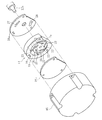
- the disassembled perspective view which shows the structure of the pump part of the same electric vacuum pump.
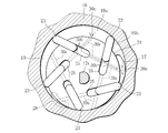
- the front view which shows a part of communicating path formed in the rotor of the pump part.
- the perspective view which shows each part of the communication path.
- the front view which shows the driving
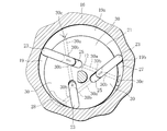
- the front view of the pump part which shows the principal part of the 2nd Embodiment of this invention.
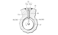
- the front view of the pump part which shows the principal part of the 4th Embodiment of this invention.
- FIG. 1 shows an electric vacuum pump (corresponding to the vane mechanism of the present application) to which the present invention is applied, together with an assist brake system of an electric vehicle (electric vehicle) incorporating the pump, and FIGS. 2 to 5 show parts of the electric vacuum pump.
- FIG. 1 is a dash panel that partitions the inside and outside of a compartment 2 of an electric vehicle (electric vehicle), and 4 is installed on the lower side of the dash panel 1.
- the negative pressure booster 5 is a hydraulic master cylinder device connected to the output side of the booster 4.
- a brake pedal 8 is provided at the end of the operating rod 6 that extends from the master cylinder device 5 into the vehicle compartment 2 through the diaphragm plate 4 a built in the booster 4.
- the hydraulic output section 5a of the master cylinder device 5 is connected to a brake device (not shown) such as a disc brake or a drum brake that applies a braking force to each wheel (front and rear wheels) of the electric vehicle via a hydraulic pipe 9.
- a brake device such as a disc brake or a drum brake that applies a braking force to each wheel (front and rear wheels) of the electric vehicle via a hydraulic pipe 9.
- the brake pedal 8 When the brake pedal 8 is depressed, the hydraulic pressure can be supplied to the brake device of each wheel while being assisted by the negative pressure (applying brake force). That is, since an electric vehicle does not have an engine that is a source of negative pressure unlike a vehicle equipped with an engine, a vacuum pump that is a vane machine, such as an electric vacuum pump 10, is provided in the negative pressure inlet portion 4 b of the booster 4. Is connected.
- the negative pressure required for assisting the brake operation is supplied from the electric vacuum pump 10 to the booster 4.
- the electric vacuum pump 10 and the booster 4 are connected by a
- the electric vacuum pump 10 includes, for example, a rotary vane type pump unit 14 connected (directly connected) to an output shaft 12a (rotary shaft) of a horizontally oriented motor unit 12, and a bottomed cylindrical pump cover 15 around the pump unit 14.
- the structure covered with is used.
- the pump unit 14 is provided with flat-shaped pump covers 18 a and 18 b on both sides of the circular pump ring 16 to form a circular cylinder chamber 19 therein.
- a circular rotor 21 connected to the output shaft 12 a of the motor unit 12 is accommodated in the cylinder chamber 19.
- the rotor 21 is disposed at a position eccentric from the center of the pump ring 16 (cylinder chamber 19), and is driven to rotate about the eccentric position.
- a plurality of, here five, vanes 23 are installed on the outer peripheral surface of the rotor 21 at regular intervals so as to protrude.
- five vane grooves 25 are provided on the outer peripheral surface of the rotor 21 at equal intervals in an oblique direction.
- the vane grooves 25 are all formed by grooves extending in the width direction of the rotor 21.
- Each vane 23 uses a vane formed in a plate shape with a carbon member so that smooth sliding can be performed without using lubricating oil (non-lubricating oil type).
- Each vane 23 is formed in a square shape corresponding to the width dimension (pump ring width) of the vane groove 25.
- Each vane 23 is slidably received in each vane groove 25 from the base end side, and the tip end side of each vane 23 is installed so as to be able to jump out (retract). That is, each vane 23 protrudes outward by a centrifugal force generated by the rotation of the rotor 21 to generate a negative pressure.
- each vane 23 comes into contact with the inner peripheral surface of the cylinder chamber 19 (the inner peripheral surface of the pump ring 16) to partition the cylinder chamber 19 into a plurality of parts. Further, each vane 23 moves while contacting the inner peripheral surface of the cylinder chamber 19 according to the rotation of the rotor 21 (sliding), for example, from the suction hole 27 formed in the pump cover 18a, for example, the pump unit 14 Air in the booster 4 is scraped out through a negative pressure suction part 17a (shown in FIG. 1) provided in the frame part 17 that supports the connection hose 11 connected to the negative pressure suction part 17a.
- a negative pressure suction part 17a shown in FIG. 1
- the scraped air is discharged to the outside (outside air) from, for example, a discharge hole 28 formed in the pump cover 18a, and the negative pressure generated at this time is supplied to the negative pressure chamber 4c partitioned by the diaphragm plate 4a.
- the negative pressure generated by the electric vacuum pump 10 is supplied to the booster 4 as a force for assisting the brake operation.
- each vane 23 a vane having a performance that can sufficiently withstand a normal assumed usage period is employed. In other words, each vane 23 strives to extend its life and prevent breakage in an assumed use situation. Even so, it is conceivable that the wear of each vane 23 reaches the wear limit and causes breakage depending on the usage situation more than expected. For example, an unlubricated electric vacuum pump using carbon vanes as a lubricant has a high tendency. Therefore, each part of the rotor 21 is provided with a vane wear prediction structure that makes it possible to predict that the wear limit of the vane 23 has been approached as shown in FIGS. This structure is configured by providing the communication path 30 in the rotor 21.
- the communication passage 30 is a passage that relays through the vane groove 25 and communicates with two different chambers in the cylinder chamber 19. When the wear of the vane 23 approaches the wear limit, the vane 23 relays the vane groove 25. Opening the passage portion intentionally induces an operation with a considerably deteriorated performance from an operation that normally exhibits normal performance.
- the communication passage 30 is formed using a straight through hole 30a that is easy to process.
- the through hole 30 a is inserted into the bottom of each vane groove 25, for example, the bottom of the center in the width direction, and the tip of a drill tool (not shown) is inserted.
- the tip of a drill tool (not shown) is inserted.
- a passage through the vane groove 25, that is, the vane groove 25 is interposed in the middle, and the vane 23 in the vane groove 25 is here between two different chambers.
- a communication passage 30 is formed to communicate between the two chambers on both sides of the wall.
- the opening 30b of the through hole 30a that opens on both wall surfaces of the vane groove 25 is normally closed by the wall surface of the vane 23 as indicated by a solid line in FIG.
- the wear limit part where a sudden pump function failure occurs due to vane wear
- the opening position is determined so that the two chambers 19a and 19b (two different chambers) arranged near the suction hole 27 communicate with each other at a predetermined position, that is, in the initial stage of suction, and the wear of the vane 23 reaches the wear limit.
- the two chambers 19 a and 19 b on both sides of the vane partitioned by the vane 23 in the initial stage of suction are connected through the communication passage 30. In other words, the pump performance is deteriorated.
- the communication path 30 may have a structure using one vane groove 25 instead of a structure using two adjacent vane grooves 25.
- the communication passages 30 are formed from the outer peripheral surfaces of the rotors on both sides of each vane groove 25 toward the bottom wall surface of the vane groove 25 and drilled in an oblique direction with a drill tool or the like, so that the bottom side of the vane groove 25 is formed.
- You may comprise from the structure of the V-shaped through-hole which connects the two chambers which made vertices apex. With this structure, it is possible to predict that the wear of the vane 23 is approaching the wear limit. That is, as shown in FIG. 5, in the electric vacuum pump 10, as the rotor 21 is driven (rotated) by the motor unit 12, each vane 23 on the outer peripheral surface protrudes outward by centrifugal force, The portion is pressed against the inner peripheral surface of the cylinder chamber 19.
- each vane 23 moves while being in contact with the inner peripheral surface of the cylinder chamber 19. At this time, due to a change (small) in the space volume of the chamber partitioned by each vane 23, air is scraped out from the suction hole 27 and exhausted from the discharge hole 28 to the atmosphere. Thereby, the negative pressure generated by the electric vacuum pump 10 is applied to the booster 4. By the operation of the electric vacuum pump 10 (normal operation), wear at the tip of each vane 23 gradually proceeds.
- the electric vacuum pump 10 Due to the occurrence of this leakage, the electric vacuum pump 10 is not an operation that exhibits the normal pump performance until then, but a considerably deteriorated pump operation in which the performance of scraping air is inferior. From the intentionally induced deterioration operation of the electric vacuum pump 10, the current operation state of the electric vacuum pump 10 is changed to a situation where the pump function may be lost due to vane wear (a situation where performance deterioration occurs suddenly). ). That is, it is possible to determine, that is, to predict that the vane 23 is approaching the wear limit from the change in the operating state of the electric vacuum pump 10 caused by the communication passage 30.
- FIG. 7 shows a main part of the second embodiment of the present invention.
- the present invention is applied to an electric vacuum pump having three vanes 23.
- the same parts as those in the first embodiment are denoted by the same reference numerals, and the description thereof is omitted. Even such an electric vacuum pump has the same effects as those of the first embodiment.
- 8 to 11 show the main part of the third embodiment of the present invention.
- the vane 23 is provided with a communication structure, so that the two chambers 19a, 19a, 19b (two different chambers) are communicated with each other so that the deterioration operation in the electric vacuum pump is easily induced.
- this embodiment is different from the first embodiment in the structure on the vane 23 side, that is, each vane 23 communicates with two different chambers 19 a and 19 b in the cylinder chamber 19.
- a through-hole 40 is formed, and the through-hole 40 is normally blocked by the wall surface of the vane groove 25, so that when the wear of the vane 23 progresses to a predetermined amount, here the wear limit L, it appears outside the vane groove 25. It is a thing.
- the through hole 40 of the vane 23 is provided so as to penetrate the vane portion accommodated in the vane groove 25 in the thickness direction.
- a rectangular opening is used for the through hole 40.
- the through hole 40 is positioned in front of the wear limit L of the vane 23 indicated by a one-dot chain line in FIG. When the vicinity of the wear limit of the vane 23 approaches the inner peripheral surface of the cylinder chamber 19, the through hole 40 starts to appear outside the vane groove 25 at the initial stage of suction.
- the through hole 40 appears outside the vane groove 25. That is, the through hole 40 is disposed in the cylinder chamber 19. Then, the two chambers 19a and 19b that should be partitioned by the vane 23 are communicated with each other through the through-opening 40, and the air in the chamber 19a leaks into the chamber 19b (adjacent chamber). This air leakage is performed together with the air leakage from the communication passage 30 described in the first embodiment, and causes a large amount of air leakage. For this reason, the electric vacuum pump is easily induced to operate with degraded pump performance.
- FIGS. 8 to 11 the same parts as those in the first embodiment are denoted by the same reference numerals, and the description thereof is omitted.
- FIG. 12 shows a main part of the fourth embodiment of the present invention.
- the present invention is applied to a vane machine in which a vane is provided on the inner peripheral surface of a cylinder chamber, for example, a vane compressor, instead of an electric vacuum pump (vane machine) in which a vane is provided in a rotor.
- the vane compressor accommodates a rotor 47 in a circular cylinder chamber 46 formed by a cylinder ring 45 so as to be eccentrically rotatable, and is provided with a vane groove 48 on the inner peripheral surface of the cylinder chamber 46.
- the vane 49 is accommodated in the groove 48 so as to protrude, and the tip of the vane 49 is configured to contact the outer peripheral surface of the rotor 47.
- the volume of the cylinder chamber 46 partitioned by the vane 49 is changed to perform the compression operation.
- communication passages 51 are provided so that when a predetermined amount of wear of the vane 49 has progressed, an operation with degraded compressor performance is induced.
- the communication passage 51 is formed by, for example, penetrating through the cylinder chamber 19 while crossing the front end side of the vane groove 48, for example, two through holes 51a on both sides of the cylinder ring 45 with the vane groove 48 interposed therebetween. Constructed (X form).
- a communication passage 51 is formed on the cylinder chamber 46 side, which relays the inside of the vane groove 48 and communicates two different chambers 46a and 46b in the cylinder chamber 46.
- the intersecting portion (passage portion) that relays the inside of the vane groove 48 of the communication passage 51 is normally closed by the vane 49 in the vane groove 48, and the wear of the vane 49 reaches a predetermined amount, here near the wear limit of the vane 49. It will be released as it progresses. As a result, even in the vane type compressor, it is possible to predict that the vane 49 is approaching the wear limit as in the first embodiment.
- the present invention may be applied to a vane machine using other vanes.
- the present invention is not limited to the first to fourth embodiments described above, and may be implemented in various ways without departing from the spirit of the present invention.
- the communication path 30 of the above-described embodiment is formed from a through hole
- the present invention is not limited to this, and a communication groove may be formed by forming a through groove on the side surface of the rotor 21 or the cylinder ring 45.
- the structure is not limited.
- the structure in which the two chambers on both sides of the vane are communicated with each other has been described.
- any structure may be used as long as the two chambers in the cylinder chamber communicate with each other. .
Landscapes
- Engineering & Computer Science (AREA)
- Mechanical Engineering (AREA)
- General Engineering & Computer Science (AREA)
- Rotary Pumps (AREA)
- Applications Or Details Of Rotary Compressors (AREA)
Description
本発明は、ベーン摩耗の予測を劣化運転により可能としたベーン機械のベーン摩耗予測構造に関する。
二次電池を電力源にモータ走行を行う電気自動車(電動車両)は、アシストブレーキシステムに求められる負圧を確保するために(アシスト力の確保)、ベーン機構である電動式のバキュームポンプが用いられている。
バキュームポンプ(ベーン機構)には、吸入穴、吐出穴を備える円形のシリンダ室、同シリンダ室内に回転自在に収められたロータ、複数枚のベーン(プレート状)を組み合わせた構造が用いられる。多くは、ロータの外周面に放射状に複数のベーン溝を形成し、これらベーン溝内にベーンの基端側を進退自在に収め、ベーンの先端部をシリンダ室の内周面と接触させることによって、シリンダ室内を複数に仕切る構造(遠心力やばね部材などによる)が用いられる。つまり、ロータの回転によりベーンをシリンダ室の内周面に沿って摺動させることで、負圧を発生させるようにしてある。
バキュームポンプ(ベーン機構)には、吸入穴、吐出穴を備える円形のシリンダ室、同シリンダ室内に回転自在に収められたロータ、複数枚のベーン(プレート状)を組み合わせた構造が用いられる。多くは、ロータの外周面に放射状に複数のベーン溝を形成し、これらベーン溝内にベーンの基端側を進退自在に収め、ベーンの先端部をシリンダ室の内周面と接触させることによって、シリンダ室内を複数に仕切る構造(遠心力やばね部材などによる)が用いられる。つまり、ロータの回転によりベーンをシリンダ室の内周面に沿って摺動させることで、負圧を発生させるようにしてある。
こうした負圧を発生させる際、ベーンの先端部は、シリンダ室の内周面と摺接するため摩耗する。通常、ベーンは、摩耗が進むと、ベーン溝内から外へ次第に繰り出されるが、摩耗限界に達するまで、ベーンが繰り出されると、ベーン強度の不足(ベーン全長が短くなるため)から、ベーンが破断するおそれがある。
ブレーキシステムに用いられるバキュームポンプは、作動時間に比例してベーンの摩耗が進むため、ベーンが摩耗限界を達すると、急激にバキュームポンプの機能を失陥させ、ブレーキシステムに大きな影響を与えてしまう。特にカーボン部材から形成したベーンを用い、潤滑油を用いずに、ベーン廻りの潤滑を行わせるバキュームポンプは、こうした摩耗の影響を受けやすい。
ブレーキシステムに用いられるバキュームポンプは、作動時間に比例してベーンの摩耗が進むため、ベーンが摩耗限界を達すると、急激にバキュームポンプの機能を失陥させ、ブレーキシステムに大きな影響を与えてしまう。特にカーボン部材から形成したベーンを用い、潤滑油を用いずに、ベーン廻りの潤滑を行わせるバキュームポンプは、こうした摩耗の影響を受けやすい。
そのため、バキュームポンプでは、通常の使用期間では十分に耐えるベーンを採用して、ベーンの寿命を延ばし、ポンプ機能が失われないように努めている。それでも、想定以上の使用状況により、ベーンの摩耗が摩耗限界に達することが考えられる。
従来は、引用文献1,2に開示されているようにベーンの側面に溝部を形成して、ベーンの気密性を高めたり、ベーンの潤滑性を高めたりする技術が提案されているだけである。
従来は、引用文献1,2に開示されているようにベーンの側面に溝部を形成して、ベーンの気密性を高めたり、ベーンの潤滑性を高めたりする技術が提案されているだけである。
このため、ベーンの摩耗限界に達する前の状況を知る由もなかった。
そこで、本発明の目的は、ベーンの摩耗が、急激な性能劣化をもたらす摩耗が摩耗限界に近付いたことを予測可能としたベーン機械のベーン摩耗予測構造を提供することにある。
そこで、本発明の目的は、ベーンの摩耗が、急激な性能劣化をもたらす摩耗が摩耗限界に近付いたことを予測可能としたベーン機械のベーン摩耗予測構造を提供することにある。
本発明は、上記目的を達成するために、ロータに、ベーン溝内を中継して、シリンダ室内の異なる二室を連通する連通路を設け、ベーン溝内を中継する連通路の通路部分が、ベーン溝に収めたベーンによって、常時は閉じ、ベーンの摩耗が所定量、進行すると開放される構成とした(請求項1)。
これにより、ベーン機械の運転にて、ベーンの摩耗が所定量まで進み、ベーンの全長が短くなると、それまでベーンによって閉じられていた連通路のベーン溝内を中継する通路部分が開放される。すると、ベーンで仕切られるはずの二室は、連通路を通じて連通する。これで、二室間で漏れが生じ、ベーン機械は、今までの正規性能を発揮する運転でなく、それよりもかなり性能が劣化した運転に変わる。
この意図的に誘発された劣化運転から、現在の状況が、ベーン摩耗が原因で急激に性能劣化が生じるおそれのある状況に近付いたこと、すなわちベーンが摩耗限界に近付いた状況であることの予測が行える。
この意図的に誘発された劣化運転から、現在の状況が、ベーン摩耗が原因で急激に性能劣化が生じるおそれのある状況に近付いたこと、すなわちベーンが摩耗限界に近付いた状況であることの予測が行える。
好ましくは、ベーンが摩耗限界に近付いていることの予測が正確に行われるよう、連通路の通路部分における開放は、ベーンが摩耗限界の近くまで摩耗したときであることとした(請求項2)。
好ましくは、さらに劣化運転が誘発されやすくなるよう、ベーンは、異なる二室を連通する貫通口を有し、この貫通口が、常時はベーン溝の壁面により塞がれ、ベーンの摩耗が所定量、進行するとベーン溝外に現れる構成も用いることとした(請求項3)。
好ましくは、さらに劣化運転が誘発されやすくなるよう、ベーンは、異なる二室を連通する貫通口を有し、この貫通口が、常時はベーン溝の壁面により塞がれ、ベーンの摩耗が所定量、進行するとベーン溝外に現れる構成も用いることとした(請求項3)。
本発明によれば、ロータに形成した連通路を用いて、意図的にベーン機械の劣化運転を誘発させることで、ベーン機械は、ベーン摩耗が原因で急激に性能劣化が生じるおそれのある状況に近付いたこと、すなわちベーン機構の運転状況の判別から、ベーンが摩耗限界に近付いた状況であることを予測することができる(請求項1)。
また、ベーンが摩耗限界に近付いていることを正確に予測することができる(請求項2)。
また、ベーン機械の劣化運転は、ベーンに形成した貫通口により、一層、誘発されやすくなる(請求項3)。
また、ベーン機械の劣化運転は、ベーンに形成した貫通口により、一層、誘発されやすくなる(請求項3)。
以下、本発明を図1ないし図6に示す第1の実施形態にもとづいて説明する。
図1は本発明を適用した電動バキュームポンプ(本願のベーン機構に相当)を、同ポンプを組み込んだ電気自動車(電動車両)のアシストブレーキシステムと共に示し、図2~5は同電動バキュームポンプの各部の構造を示している。
まず、図1を参照してアシストブレーキシステムaの概略を説明すると、図中1は電気自動車(電動車両)の車室2の内外を仕切るダッシュパネル、4は同ダッシュパネル1の下段側に据付けた負圧式の倍力装置、5は同倍力装置4の出力側に接続された油圧式のマスタシリンダ装置である。マスタシリンダ装置5から倍力装置4内蔵のダイヤフラムプレート4aを通じ車室2内へ延びているオペレーティングロッド6の端部には、ブレーキペダル8が設けられている。
図1は本発明を適用した電動バキュームポンプ(本願のベーン機構に相当)を、同ポンプを組み込んだ電気自動車(電動車両)のアシストブレーキシステムと共に示し、図2~5は同電動バキュームポンプの各部の構造を示している。
まず、図1を参照してアシストブレーキシステムaの概略を説明すると、図中1は電気自動車(電動車両)の車室2の内外を仕切るダッシュパネル、4は同ダッシュパネル1の下段側に据付けた負圧式の倍力装置、5は同倍力装置4の出力側に接続された油圧式のマスタシリンダ装置である。マスタシリンダ装置5から倍力装置4内蔵のダイヤフラムプレート4aを通じ車室2内へ延びているオペレーティングロッド6の端部には、ブレーキペダル8が設けられている。
またマスタシリンダ装置5の油圧出力部5aは、油圧配管9を介して、電気自動車の各車輪(前後輪)に制動力を付与するディスク式ブレーキやドラム式ブレーキなどブレーキ装置(図示しない)が接続され、ブレーキペダル8を踏み込むと、負圧でアシストされながら、各輪のブレーキ装置へ油圧を供給できるようにしている(ブレーキ力の付与)。
すなわち、電気自動車は、エンジン搭載車のような負圧発生源となるエンジンが無いため、倍力装置4の負圧入口部4bには、ベーン機械であるところのバキュームポンプ、例えば電動バキュームポンプ10が接続される。これで、電動バキュームポンプ10から倍力装置4へ、ブレーキ操作のアシストに求められる負圧が供給されるようにしている。ちなみに電動バキュームポンプ10と倍力装置4間は、接続ホース11により接続され、アシストブレーキシステムaの全体を構成している。
すなわち、電気自動車は、エンジン搭載車のような負圧発生源となるエンジンが無いため、倍力装置4の負圧入口部4bには、ベーン機械であるところのバキュームポンプ、例えば電動バキュームポンプ10が接続される。これで、電動バキュームポンプ10から倍力装置4へ、ブレーキ操作のアシストに求められる負圧が供給されるようにしている。ちなみに電動バキュームポンプ10と倍力装置4間は、接続ホース11により接続され、アシストブレーキシステムaの全体を構成している。
電動バキュームポンプ10は、例えば横向きのモータ部12の出力軸12a(回転軸)に、ロータリベーン式のポンプ部14を連結(直結)し、ポンプ部14の周りを有底筒形のポンプカバー15で覆う構造が用いられている。
具体的には、図2に示されるようにポンプ部14は、円形のポンプリング16の両側に、それぞれ平板状のポンプカバー18a,18bを据付けて、内部に円形のシリンダ室19を形成する。このシリンダ室19内に、モータ部12の出力軸12aと連結した円形のロータ21が収められる。ロータ21は、ポンプリング16(シリンダ室19)の中心とは偏心した位置に配置され、この偏心した位置を中心に回転駆動される。
具体的には、図2に示されるようにポンプ部14は、円形のポンプリング16の両側に、それぞれ平板状のポンプカバー18a,18bを据付けて、内部に円形のシリンダ室19を形成する。このシリンダ室19内に、モータ部12の出力軸12aと連結した円形のロータ21が収められる。ロータ21は、ポンプリング16(シリンダ室19)の中心とは偏心した位置に配置され、この偏心した位置を中心に回転駆動される。
このロータ21の外周面には、等間隔で、複数枚、ここでは5枚のベーン23が突出可能に据付けられている。具体的には、ロータ21の外周面には、5個のベーン溝25が、斜めの向きで等間隔に設けられている。ベーン溝25は、いずれもロータ21の幅方向に渡る溝で形成されている。各ベーン23には、いずれも潤滑油を用いずに円滑な摺動が行えるよう(無潤滑油式)、カーボン部材でプレート状に形成したベーンが用いられている。各ベーン23は、ベーン溝25の幅寸法(ポンプリング幅)に応じた角形形状に形成されている。これら各ベーン23が基端側から各ベーン溝25内に摺動自在に収められ、各ベーン23の先端側を周囲へ飛び出し可能(進退可能)に据付けている。つまり、各ベーン23は、ロータ21の回転により生ずる遠心力にて、外側へ張り出て、負圧を発生させる。
すなわち、ロータ21の回転により、各ベーン23の先端部は、シリンダ室19の内周面(ポンプリング16の内周面)と接触してシリンダ室19を複数に仕切る。さらに各ベーン23が、ロータ21の回転にしたがい、シリンダ室19の内周面と接しながら移動することにより(摺動)、例えばポンプカバー18aに形成してある吸入穴27から、例えばポンプ部14を支えるフレーム部17に設けた負圧吸入部17a(図1に図示)、同負圧吸入部17aとつながる接続ホース11を通じて、倍力装置4内の空気が掻き出されるようにしている。つまり、掻き出した空気は、例えばポンプカバー18aに形成された吐出穴28から外部(外気)へ吐出され、このとき発生する負圧が、ダイヤフラムプレート4aで仕切られた負圧室4cへ供給される。これで、電動バキュームポンプ10の発生する負圧が、ブレーキ操作をアシストする力として、倍力装置4へ供給される。
ここで、各ベーン23は、通常の想定し得る使用期間では十分に耐える性能を有するベーンが採用されている。つまり、各ベーン23は、寿命を延ばし、想定し得る使用状況では破断が生じないように努めている。それでも、想定以上の使用状況により、各ベーン23の摩耗が摩耗限界に達して破断を招くことが考えられる。例えば、カーボン製ベーンを潤滑材として用いる無潤滑式の電動バキュームポンプは、その傾向が高い。
そこで、ロータ21の各部には、図3~図5に示されるようなベーン23の摩耗限界に近付いたことを予測可能にするベーン摩耗予測構造が設けられている。同構造は、ロータ21に連通路30を設けて構成されるものである。連通路30は、ベーン溝25内を中継して、シリンダ室19内の異なる二室を連通する通路で構成され、ベーン23の摩耗が摩耗限界に近付くと、ベーン23がベーン溝25を中継する通路部分を開放して、意図的に、通常の正規性能を発揮している運転から、それよりもかなり性能の劣化した運転を誘発するものである。
そこで、ロータ21の各部には、図3~図5に示されるようなベーン23の摩耗限界に近付いたことを予測可能にするベーン摩耗予測構造が設けられている。同構造は、ロータ21に連通路30を設けて構成されるものである。連通路30は、ベーン溝25内を中継して、シリンダ室19内の異なる二室を連通する通路で構成され、ベーン23の摩耗が摩耗限界に近付くと、ベーン23がベーン溝25を中継する通路部分を開放して、意図的に、通常の正規性能を発揮している運転から、それよりもかなり性能の劣化した運転を誘発するものである。
ここでは、連通路30は、加工しやすい直線状の貫通孔30aを用いて形成している。具体的には図3~図5に示されるように貫通孔30aは、各ベーン溝25の底部、例えば幅方向中央の底部分へ、ドリル工具(図示しない)の先端部を差し込み、ベーン溝25の全長に沿ってドリル加工を行い、隣接するベーン溝25の底側の両壁面を突き通し、そのままロータ21の外周面まで突き抜けるまでドリル加工を施すことによって形成されている。つまり、貫通孔30aは、ベーン溝25の底部から、同ベーン溝25と隣接するベーン溝25内を貫通して、ロータ21の外周面に開口する。このベーン溝25の底部から延びる貫通孔30aの組合わせから、ベーン溝25を中継した通路、すなわち途中にベーン溝25を介在させて、異なる二室間、ここでは当該ベーン溝25内のベーン23を挟んだ両側の二室間を連通する連通路30を形成している。
さらに述べると、ベーン溝25の両壁面に開口する貫通孔30aの開口部30bは、例えば図3中の実線のように通常時は、ベーン23の壁面によって閉じられ、ベーン23の先端部での摩耗が所定量まで進行したとき、具体的には例えば図3中の二点鎖線のように摩耗限界(ベーン摩耗を原因として急激なポンプ機能の失陥が生じるとされる部位)の近くまで摩耗したときに開放される位置に形成されている。
特に開放する位置は、所定位置、すなわち吸入初期のとき、吸入穴27の近くに配置される二室19a,19b(異なる二室)を連通させるように位置決められ、ベーン23の摩耗が摩耗限界に近付くと、吸入初期のベーン23で仕切られるベーン両側の二室19a,19bを連通路30を通じ連通させる。つまり、ポンプ性能の劣化した運転が行える構造としている。
特に開放する位置は、所定位置、すなわち吸入初期のとき、吸入穴27の近くに配置される二室19a,19b(異なる二室)を連通させるように位置決められ、ベーン23の摩耗が摩耗限界に近付くと、吸入初期のベーン23で仕切られるベーン両側の二室19a,19bを連通路30を通じ連通させる。つまり、ポンプ性能の劣化した運転が行える構造としている。
ちなみに、連通路30は、隣合う2つのベーン溝25を利用した構造でなく、1つのベーン溝25を利用した構造でもよい。例えば連通路30は、各ベーン溝25の両側のロータの外周面から、ベーン溝25の底側の壁面に向かい、ドリル工具などで、斜め方向からそれぞれ穿設して、ベーン溝25の底側を頂点とした二室を連通するV形の貫通孔の構造から構成しても構わない。
同構造により、ベーン23の摩耗が摩耗限界に近付いていることの予測が行える。
すなわち、図5に示されるように電動バキュームポンプ10は、モータ部12によりロータ21が駆動(回転)されるにしたがい、外周面上の各ベーン23が、遠心力により外側へ張り出て、先端部をシリンダ室19の内周面に押し付ける。
同構造により、ベーン23の摩耗が摩耗限界に近付いていることの予測が行える。
すなわち、図5に示されるように電動バキュームポンプ10は、モータ部12によりロータ21が駆動(回転)されるにしたがい、外周面上の各ベーン23が、遠心力により外側へ張り出て、先端部をシリンダ室19の内周面に押し付ける。
すると、各ベーン23は、シリンダ室19の内周面と接触しながら移動する。このときの各ベーン23で仕切られた室の空間容積の変化(小)により、吸入穴27から空気を掻き出し、吐出穴28から大気へ排気する。これにより、電動バキュームポンプ10で発生した負圧が倍力装置4へ与えられる。
こうした電動バキュームポンプ10の作動により(通常運転)、各ベーン23の先端部における摩耗は次第に進行する。
こうした電動バキュームポンプ10の作動により(通常運転)、各ベーン23の先端部における摩耗は次第に進行する。
このとき、ベーン先端部が、想定を越えるポンプ機能の稼働などから、摩耗限界(急激にポンプ性能の失陥が生じるとされる)に近付くまで摩耗が進行したとする(ベーン全長:短)。
すると、図6に示されるようにベーン23の大きく張り出す吸入初期の段階のとき、全長の短くなったベーン23により、同段階にある二つのベーン溝25の壁面の開口部30bが開放され始まる。
すると、図6に示されるようにベーン23の大きく張り出す吸入初期の段階のとき、全長の短くなったベーン23により、同段階にある二つのベーン溝25の壁面の開口部30bが開放され始まる。
これにより、図6に示されるようにベーン23で仕切られるはずの初期段階の二室19a,19b(隣室)は、二つのベーン溝25の各開口部30bを中継部として、貫通孔30aを通じ、連通し始める。すると、室19a内に閉じ込められる空気は、図6中の矢印に示されるように二つのベーン溝25、連通路30を通じ、ロータ21の外周面に開口する開口部30cから、隣室の室19bに漏れ出す。この漏れの発生により、電動バキュームポンプ10は、それまでの正規のポンプ性能を発揮する運転でなく、空気を掻き出す性能が劣る、かなり劣化したポンプ運転となる。
この意図的に誘発された電動バキュームポンプ10の劣化運転から、現在の電動バキュームポンプ10の運転状況が、ベーン摩耗が原因でポンプ機能の失陥するおそれのある状況(急激に性能劣化が生じる状況)に近付いていることと認識できる。つまり、連通路30がもたらす電動バキュームポンプ10の運転状況の変化から、ベーン23が摩耗限界に近付いているとの判別、すなわち予測ができる。
この意図的に誘発された電動バキュームポンプ10の劣化運転から、現在の電動バキュームポンプ10の運転状況が、ベーン摩耗が原因でポンプ機能の失陥するおそれのある状況(急激に性能劣化が生じる状況)に近付いていることと認識できる。つまり、連通路30がもたらす電動バキュームポンプ10の運転状況の変化から、ベーン23が摩耗限界に近付いているとの判別、すなわち予測ができる。
それ故、この予測から、電動バキュームポンプ10(ベーン機械)における不測の事態の発生を未然に回避することができる。しかも、ベーン23の交換時期も知ることができ、安全性や信頼性の向上を図ることができる。カーボン製のベーン23を用いて、潤滑油を不要(無潤滑油式)とした電動バキュームポンプ10(ベーン機械)には有効である。
特に、ベーン23の摩耗限界の近くで連通路30を開放(開口部30bの開放)させたことにより、ベーン23が摩耗限界の直前の状況であることを、正確に予測することができる。
むろん、電動バキュームポンプ10を用いたアシストブレーキシステムaは、この予測により、たとえ電動バキュームポンプ10が想定を越える稼働をしていても、アシスト機能が損傷する事態を未然に回避することができる。
特に、ベーン23の摩耗限界の近くで連通路30を開放(開口部30bの開放)させたことにより、ベーン23が摩耗限界の直前の状況であることを、正確に予測することができる。
むろん、電動バキュームポンプ10を用いたアシストブレーキシステムaは、この予測により、たとえ電動バキュームポンプ10が想定を越える稼働をしていても、アシスト機能が損傷する事態を未然に回避することができる。
図7は、本発明の第2の実施形態の要部を示す。
本実施形態は、3枚のベーン23を有して構成される電動バキュームポンプに本発明を適用したものである。図7において、第1の実施形態と同じ部分には同一符号を付してその説明を省略した。
このような電動バキュームポンプでも、第1の実施形態と同様の作用効果を奏する。
図8~図11は、本発明の第3の実施形態の要部を示す。
本実施形態は、第1の実施形態のようにロータ21に隣室19a,19bを連通させる構造を設けるだけでなく、ベーン23にも連通構造を設けて、吸入初期の段階にある二室19a,19b(異なる二室)を連通させ、電動バキュームポンプにおける劣化運転を誘発されやすくしたものである。
本実施形態は、3枚のベーン23を有して構成される電動バキュームポンプに本発明を適用したものである。図7において、第1の実施形態と同じ部分には同一符号を付してその説明を省略した。
このような電動バキュームポンプでも、第1の実施形態と同様の作用効果を奏する。
図8~図11は、本発明の第3の実施形態の要部を示す。
本実施形態は、第1の実施形態のようにロータ21に隣室19a,19bを連通させる構造を設けるだけでなく、ベーン23にも連通構造を設けて、吸入初期の段階にある二室19a,19b(異なる二室)を連通させ、電動バキュームポンプにおける劣化運転を誘発されやすくしたものである。
同実施形態は、図8、図9および図10に示されるように第1の実施形態に、ベーン23側の構造、すなわち各ベーン23にシリンダ室19内の異なる二室19a,19bを連通させる貫通口40を形成し、同貫通口40が、常時はベーン溝25の壁面により塞がれ、ベーン23の摩耗が所定量、ここでは摩耗限界Lに進行すると、ベーン溝25外に現れるようにしたものである。
具体的には、ベーン23の貫通口40は、ベーン溝25内に収められるベーン部分に厚み方向を貫通するように設けられる。ここでは、貫通口40には、例えば角形の開口部が用いられる。同貫通口40は、図8中に一点鎖線で示すベーン23の摩耗限界L(ベーン摩耗を原因として急激なポンプ機能の失陥が生じるとされる部位)の手前、摩耗限界Lの直前位置に配置され、ベーン23の摩耗限界付近がシリンダ室19の内周面に近付くと、吸入初期の段階のとき、貫通口40がベーン溝25外に現れ始めるようにしている。
具体的には、ベーン23の貫通口40は、ベーン溝25内に収められるベーン部分に厚み方向を貫通するように設けられる。ここでは、貫通口40には、例えば角形の開口部が用いられる。同貫通口40は、図8中に一点鎖線で示すベーン23の摩耗限界L(ベーン摩耗を原因として急激なポンプ機能の失陥が生じるとされる部位)の手前、摩耗限界Lの直前位置に配置され、ベーン23の摩耗限界付近がシリンダ室19の内周面に近付くと、吸入初期の段階のとき、貫通口40がベーン溝25外に現れ始めるようにしている。
これにより、図11に示されるようにベーン23の摩耗が摩耗限界に近付くと、貫通口40が、ベーン溝25外に現れる。つまり、貫通口40は、シリンダ室19内に配置される。すると、ベーン23で仕切られるはずの二室19a,19bは、貫通口40で連通され、室19aの空気が室19b(隣室)に漏れる。
この空気の漏れが、第1の実施形態で述べた連通路30からの空気の漏れと共に行われ、大量の空気の漏れをもたらす。このため、電動バキュームポンプは、ポンプ性能を劣化させた運転が誘発されやすくなる。
なお、図8~図11において、第1の実施形態と同じ部分には同一符号を付してその説明を省略した。
この空気の漏れが、第1の実施形態で述べた連通路30からの空気の漏れと共に行われ、大量の空気の漏れをもたらす。このため、電動バキュームポンプは、ポンプ性能を劣化させた運転が誘発されやすくなる。
なお、図8~図11において、第1の実施形態と同じ部分には同一符号を付してその説明を省略した。
図12は、本発明の第4の実施形態の要部を示す。
本実施形態は、ロータにベーンを設けた電動バキュームポンプ(ベーン機械)でなく、シリンダ室の内周面にベーンを設けたベーン機械、例えばベーン式コンプレッサに本発明を適用したものである。
具体的には、ベーン式コンプレッサは、シリンダリング45で形成される円形のシリンダ室46内にロータ47を偏心回転可能に収め、シリンダ室46の内周面に、ベーン溝48を設け、同ベーン溝48内にベーン49を突出可能に収め、同ベーン49の先端部をロータ47の外周面に接触させる構造で構成され、ロータ47をシリンダ室46の内周面と接触させながら回転することにより、ベーン49で仕切られるシリンダ室46内の容積が変化して圧縮運転を行う。
本実施形態は、ロータにベーンを設けた電動バキュームポンプ(ベーン機械)でなく、シリンダ室の内周面にベーンを設けたベーン機械、例えばベーン式コンプレッサに本発明を適用したものである。
具体的には、ベーン式コンプレッサは、シリンダリング45で形成される円形のシリンダ室46内にロータ47を偏心回転可能に収め、シリンダ室46の内周面に、ベーン溝48を設け、同ベーン溝48内にベーン49を突出可能に収め、同ベーン49の先端部をロータ47の外周面に接触させる構造で構成され、ロータ47をシリンダ室46の内周面と接触させながら回転することにより、ベーン49で仕切られるシリンダ室46内の容積が変化して圧縮運転を行う。
このうち、ベーン溝48を挟んだシリンダリング45の両側には、ベーン49の摩耗が所定量、進行したとき、コンプレッサ性能を劣化させた運転が誘発されるよう、連通路51が設けてある。同連通路51は、例えばベーン溝48を挟んだシリンダリング45の両側に、ベーン溝48の先端側とクロスしながらシリンダ室19に突き抜ける貫通路、例えば2本の貫通孔51aを穿設して構成される(X形)。これで、シリンダ室46側に、ベーン溝48内を中継し、シリンダ室46内の異なる二室46a,46bを連通する連通路51を形成している。連通路51のベーン溝48内を中継する交差部分(通路部分)は、ベーン溝48内のベーン49によって、常時は閉じ、ベーン49の摩耗が所定量、ここではベーン49の摩耗限界の近くまで進行すると開放されるようにしてある。
これにより、ベーン式コンプレッサでも、第1の実施形態と同様、ベーン49が摩耗限界に近付いているとの予測ができる。むろん、他のベーンを用いたベーン機械に本発明を適用しても構わない。
これにより、ベーン式コンプレッサでも、第1の実施形態と同様、ベーン49が摩耗限界に近付いているとの予測ができる。むろん、他のベーンを用いたベーン機械に本発明を適用しても構わない。
なお、本発明は、上記した第1~4の実施形態に限定されるものではなく、本発明の主旨を逸脱しない範囲内で種々可変して実施してもよい。例えば上述した実施形態の連通路30は、貫通孔から形成したが、これに限らず、ロータ21やシリンダリング45の側面に貫通溝を形成して連通孔を構成してもよく、連通孔の構造には限定されるものではない。また第1~3の実施形態では、ベーン両側の二室を連通する構造を挙げたが、シリンダ室内の異なる二室を連通させる構造であればよく、要は劣化運転を誘発しさえすればよい。
10 電動バキュームポンプ(ベーン機械)
19 シリンダ室
21 ロータ
23 ベーン
25 ベーン溝
30 連通路
30a 貫通孔
40 貫通口
19 シリンダ室
21 ロータ
23 ベーン
25 ベーン溝
30 連通路
30a 貫通孔
40 貫通口
Claims (3)
- 円形のシリンダ室と、同シリンダ室内に設けられたロータと、前記シリンダ室の内周面および前記ロータの外周面のうちの一方に形成されたベーン溝と、同ベーン溝内に突出自在に収められ、先端部が前記シリンダ室の内周面および前記ロータの外周面のうちの他方の周面と接し前記シリンダ室内を複数の室に仕切るベーンとを有し、前記ベーンが、先端部での摩耗にしたがい前記ベーン溝内から繰り出されるベーン機械において、
前記ロータに、前記ベーン溝内を中継して、前記シリンダ室内の異なる二室を連通する連通路を設け、
前記ベーン溝内を中継する前記連通路の通路部分が、前記ベーン溝に収めた前記ベーンによって、常時は閉じ、前記ベーンの摩耗が所定量、進行すると開放される
ことを特徴とするベーン機械のベーン摩耗予測構造。 - 前記連通路の通路部分は、前記ベーンが摩耗限界の近くまで摩耗したとき、開放するものであることを特徴とする請求項1に記載のベーン機械のベーン摩耗予測構造。
- 更に、前記ベーンは、前記異なる二室を連通する貫通口を有し、
前記貫通口が、常時はベーン溝の壁面により塞がれ、前記ベーンの摩耗が所定量、進行すると前記ベーン溝外に現れる
ことを特徴とする請求項1または請求項2に記載のベーン機械のベーン摩耗予測構造。
Applications Claiming Priority (2)
| Application Number | Priority Date | Filing Date | Title |
|---|---|---|---|
| JP2012-156544 | 2012-07-12 | ||
| JP2012156544A JP5816140B2 (ja) | 2012-07-12 | 2012-07-12 | ベーン機械のベーン摩耗予測構造 |
Publications (1)
| Publication Number | Publication Date |
|---|---|
| WO2014010677A1 true WO2014010677A1 (ja) | 2014-01-16 |
Family
ID=49916118
Family Applications (1)
| Application Number | Title | Priority Date | Filing Date |
|---|---|---|---|
| PCT/JP2013/068998 Ceased WO2014010677A1 (ja) | 2012-07-12 | 2013-07-11 | ベーン機械のベーン摩耗予測構造 |
Country Status (2)
| Country | Link |
|---|---|
| JP (1) | JP5816140B2 (ja) |
| WO (1) | WO2014010677A1 (ja) |
Cited By (1)
| Publication number | Priority date | Publication date | Assignee | Title |
|---|---|---|---|---|
| US12049827B2 (en) | 2022-03-31 | 2024-07-30 | Goodrich Corporation | Vane wearing detection |
Families Citing this family (2)
| Publication number | Priority date | Publication date | Assignee | Title |
|---|---|---|---|---|
| JP6826660B2 (ja) | 2017-04-28 | 2021-02-03 | 株式会社ミクニ | ベーンポンプ |
| DE112017007488B4 (de) * | 2017-04-28 | 2024-03-14 | Mikuni Corporation | Flügelzellenpumpe |
Citations (3)
| Publication number | Priority date | Publication date | Assignee | Title |
|---|---|---|---|---|
| JPS62108582U (ja) * | 1985-12-26 | 1987-07-10 | ||
| JPH0211885A (ja) * | 1988-06-30 | 1990-01-16 | Ulvac Corp | 油回転真空ポンプ |
| JP2006144682A (ja) * | 2004-11-22 | 2006-06-08 | Matsushita Electric Ind Co Ltd | 気体ポンプ |
-
2012
- 2012-07-12 JP JP2012156544A patent/JP5816140B2/ja not_active Expired - Fee Related
-
2013
- 2013-07-11 WO PCT/JP2013/068998 patent/WO2014010677A1/ja not_active Ceased
Patent Citations (3)
| Publication number | Priority date | Publication date | Assignee | Title |
|---|---|---|---|---|
| JPS62108582U (ja) * | 1985-12-26 | 1987-07-10 | ||
| JPH0211885A (ja) * | 1988-06-30 | 1990-01-16 | Ulvac Corp | 油回転真空ポンプ |
| JP2006144682A (ja) * | 2004-11-22 | 2006-06-08 | Matsushita Electric Ind Co Ltd | 気体ポンプ |
Cited By (1)
| Publication number | Priority date | Publication date | Assignee | Title |
|---|---|---|---|---|
| US12049827B2 (en) | 2022-03-31 | 2024-07-30 | Goodrich Corporation | Vane wearing detection |
Also Published As
| Publication number | Publication date |
|---|---|
| JP5816140B2 (ja) | 2015-11-18 |
| JP2014020213A (ja) | 2014-02-03 |
Similar Documents
| Publication | Publication Date | Title |
|---|---|---|
| JP4165608B1 (ja) | ベーン式バキュームポンプ | |
| JP5816140B2 (ja) | ベーン機械のベーン摩耗予測構造 | |
| KR101519698B1 (ko) | 베인 로터리 압축기 | |
| CN106968949B (zh) | 真空泵 | |
| JP2014005795A (ja) | 回転型圧縮機 | |
| JP2009529116A (ja) | 静止及び回転シリンダ部品がある羽根型機械 | |
| JP5949386B2 (ja) | ベーン型圧縮機 | |
| JP4702145B2 (ja) | 斜板式圧縮機 | |
| CN103016339A (zh) | 轴密封装置及使用该轴密封装置的泵装置 | |
| JP5964848B2 (ja) | ロータリーピストン機械、特にロータリーエンジン | |
| JP6008098B2 (ja) | バキュームポンプの耐久寿命判定装置 | |
| US9358967B2 (en) | Rotary pump and braking system having the same | |
| JP2008157175A (ja) | 回転式ポンプ | |
| JP5598222B2 (ja) | 軸シール装置とそれを用いたポンプ装置及びブレーキ液圧制御装置 | |
| JP6120486B2 (ja) | ベーン機械のベーン摩耗予測構造 | |
| CN204532827U (zh) | 密闭型压缩机 | |
| KR20130057901A (ko) | 베인 로터리 압축기 | |
| JP2014125907A (ja) | 回転式ポンプおよびそれを備えたブレーキ装置 | |
| JP2009264160A (ja) | ベーンロータリ型圧縮機 | |
| JP2015148206A (ja) | 回転式ポンプ | |
| JP2007309281A (ja) | ベーンロータリ型圧縮機 | |
| JP3975857B2 (ja) | 回転式ポンプ及びその回転式ポンプを備えたブレーキ装置 | |
| JP2012036807A (ja) | ベーンポンプ | |
| RU2602951C1 (ru) | Лопастной вакуумный насос | |
| JP2009091973A (ja) | 真空ポンプ |
Legal Events
| Date | Code | Title | Description |
|---|---|---|---|
| 121 | Ep: the epo has been informed by wipo that ep was designated in this application |
Ref document number: 13817100 Country of ref document: EP Kind code of ref document: A1 |
|
| NENP | Non-entry into the national phase |
Ref country code: DE |
|
| 122 | Ep: pct application non-entry in european phase |
Ref document number: 13817100 Country of ref document: EP Kind code of ref document: A1 |