WO2014010451A1 - ヒドロホルミル化触媒損失防止法 - Google Patents
ヒドロホルミル化触媒損失防止法 Download PDFInfo
- Publication number
- WO2014010451A1 WO2014010451A1 PCT/JP2013/068008 JP2013068008W WO2014010451A1 WO 2014010451 A1 WO2014010451 A1 WO 2014010451A1 JP 2013068008 W JP2013068008 W JP 2013068008W WO 2014010451 A1 WO2014010451 A1 WO 2014010451A1
- Authority
- WO
- WIPO (PCT)
- Prior art keywords
- glass fiber
- rhodium
- mist
- wire mesh
- candle filter
- Prior art date
- Legal status (The legal status is an assumption and is not a legal conclusion. Google has not performed a legal analysis and makes no representation as to the accuracy of the status listed.)
- Ceased
Links
Images



Classifications
-
- C—CHEMISTRY; METALLURGY
- C07—ORGANIC CHEMISTRY
- C07C—ACYCLIC OR CARBOCYCLIC COMPOUNDS
- C07C45/00—Preparation of compounds having >C = O groups bound only to carbon or hydrogen atoms; Preparation of chelates of such compounds
- C07C45/49—Preparation of compounds having >C = O groups bound only to carbon or hydrogen atoms; Preparation of chelates of such compounds by reaction with carbon monoxide
- C07C45/50—Preparation of compounds having >C = O groups bound only to carbon or hydrogen atoms; Preparation of chelates of such compounds by reaction with carbon monoxide by oxo-reactions
-
- B—PERFORMING OPERATIONS; TRANSPORTING
- B01—PHYSICAL OR CHEMICAL PROCESSES OR APPARATUS IN GENERAL
- B01D—SEPARATION
- B01D46/00—Filters or filtering processes specially modified for separating dispersed particles from gases or vapours
- B01D46/24—Particle separators, e.g. dust precipitators, using rigid hollow filter bodies
- B01D46/2403—Particle separators, e.g. dust precipitators, using rigid hollow filter bodies characterised by the physical shape or structure of the filtering element
- B01D46/2407—Filter candles
Definitions
- the present invention relates to a process for producing aldehydes by hydroformylating an olefin with carbon monoxide and hydrogen (hereinafter, a mixture of carbon monoxide and hydrogen is used as synthesis gas) in the presence of a rhodium-phosphorus compound complex. It relates to a method for preventing the loss of rhodium catalyst from the reactor using a specially modified candle filter in order to keep the loss of expensive rhodium catalyst almost completely to zero.
- Rhodium is a precious and expensive precious metal that produces only a dozen tons a year worldwide. Therefore, in the industry using rhodium, it is important to use it while preventing loss for as long as possible.
- gaseous olefin and synthesis gas are fed into a hydroformylation reactor containing a rhodium-phosphorus complex catalyst dissolved in an organic solvent, and the aldehyde produced in the reaction is combined with unreacted olefin gas and synthesis gas. Evaporate and remove the resulting aldehyde from the reactor.
- rhodium catalyst is entrained and lost along with the crude aldehyde mist in evaporating the aldehyde from the reactor. Therefore, the activity of the reaction may be reduced due to the loss of the physical catalyst.
- a mist separator specially devised to remove the mist containing the rhodium catalyst almost completely and prevent loss of the rhodium catalyst is installed at the steam outlet from the reactor. (See FIG. 1).
- This mist removal operation is an important operation along with the reaction in the process of producing aldehydes by a hydroformylation reaction.
- Non-patent Document 1 Normally, general-purpose mist separators used in chemical equipment are often used individually, such as cyclones, demisters, and filters, but this method is difficult to meet the performance requirements of the hydroformylation reaction process. Therefore, the separation of the mist containing the rhodium catalyst has been devised so that it can be almost completely removed by arranging the devices having the following separation functions in three stages. First stage: cyclone separator, second stage: demister, and third stage: candle filter, and in particular, the structure of the third stage candle filter is important for almost complete removal.
- a mist separator provided at the reactor outlet is used to prevent loss of rhodium catalyst entrained by the product aldehyde evaporated and removed from the reactor.
- Conventional candle filters are fragile, and glass fibers attached to the inside are also bonded with an adhesive. As a result, a part of the candle filter was damaged in the first half of the long-term continuous operation, and the rhodium catalyst was lost.
- a candle filter with a strong structure is used.
- the hydroformylation reaction process (using a rhodium-phosphorus compound complex catalyst) for producing aldehydes is accompanied by the aldehyde evaporated and removed from the reactor. Loss of rhodium catalyst can be prevented, and long-term continuous operation for two years or more is possible.
- the adhesive is not used for attaching the member for removing mist provided at the reactor outlet, the members are overlapped and bundled with a wire mesh band, A method to prevent loss of rhodium catalyst by installing a candle filter that can withstand continuous operation.
- the candle filter is a combination of wire mesh, wire mesh band and glass fiber in the order of 3 to 7 pairs, cotton belt, wire mesh, punching plate, a total of 12
- the present invention improves the mist separator candle filter in the process of hydroformylating olefins in the presence of rhodium-phosphorus compound complexes with carbon monoxide and hydrogen to produce aldehydes, reducing the loss of rhodium catalyst from the reactor. It relates to a method to prevent. According to the present invention, the amount of annual loss of the rhodium catalyst can be made extremely small, and continuous operation for 2 years can be performed while maintaining the amount, so that the cost of the rhodium catalyst can be suppressed.
- the present invention relates to loss of rhodium catalyst. That is, in the process of producing aldehydes by hydroformylating an olefin with carbon monoxide and hydrogen in the presence of a rhodium-phosphorus compound complex, a mist separator is used to remove aldehyde mist in the gas evaporated from the reactor.
- the present invention relates to a method for preventing the loss of rhodium catalyst from a reactor. When the conventional candle filter was used, the rhodium concentration in the produced aldehyde after the start of operation was 5 wt ppb or less.
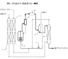
- Outline flow sheet A flow sheet for equipment installation in the reaction system of the present invention is shown in FIG. The case where propylene was used as an olefin was illustrated.
- Propylene and synthesis gas as raw materials are removed from catalyst poisons in purification towers 1 and 2, respectively.
- Purified propylene is fed to the reactor 3 of the reaction system.
- Butyraldehyde as a reaction product is evaporated from the reactor together with the unreacted gas, and a very small amount of rhodium catalyst contained in the evaporated product is separated by the mist separator 4 and returned to the reactor in the reaction system.
- the mixture of evaporated butyraldehyde, unreacted propylene and synthesis gas is cooled by the condenser 5. Further, the gas-liquid separator 6 separates liquid butyraldehyde, gaseous unreacted propylene, and synthesis gas.
- Gaseous propylene and synthesis gas are circulated to the reaction system via the circulation blower 7.
- the condensed butyraldehyde is fed to the top of the countercurrent tower 8 and a predetermined amount of purified synthesis gas supplied to the reaction system is supplied from the lower part of the countercurrent tower 8 to remove propylene dissolved in butyraldehyde. To do. Crude butyraldehyde is extracted from the lower part of the countercurrent tower 8.
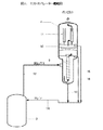
- FIG. 2 shows the arrangement of equipment and the gas flow in the mist separator of the present invention.
- the reaction product gas generated in the reactor 3 described with reference to FIG. 2 is introduced from the upper part of the reactor 3 into the first stage separator (cyclone separator 9) of the mist separator 4 through the pipe 12. Most of the mist contained in the reaction product gas is removed by the cyclone separator 9, and the mist returns from the pipe line 13 to the reactor 3 through the pipe line 14. The reaction product gas from which most of the mist has been removed is further separated by a second stage separator (demister 10). The mist returns from the line 16 to the reactor 3 via the line 14. The reaction product gas that has passed through the demister 10 is introduced into a third stage separator (candle filter 11) to further remove a trace amount of residual mist. The mist returns from the line 15 to the reactor 3 via the line 14. The reaction product gas from which the mist has been removed is also almost completely separated from the rhodium catalyst, and is introduced into the next step from the upper gas outlet of the mist separator 4.
- the wire mesh (40-60 mesh) 25 the glass fiber ( ⁇ 0.8 ⁇ m) 24, the glass fiber ( ⁇ 3 ⁇ m) 23, wire mesh band (40-60 mesh) 22, glass fiber ( ⁇ 1.3 ⁇ m) 21, glass fiber ( ⁇ 0.8 ⁇ m) 20, cotton belt (100-150 mesh) 19, wire mesh (40-60 mesh) 18 is a structure in which nine types of members such as a punching plate 17 are attached.
- Glass fiber ( ⁇ 0.8 ⁇ m) 24, glass fiber ( ⁇ 3 ⁇ m) 23, glass fiber ( ⁇ m1.3) 21, and glass fiber ( ⁇ 0.8 ⁇ m) 20 have joints in the circumferential direction and the longitudinal direction. Since the adhesive was used, it was deteriorated by the reaction product, and it was a cause of slipping off. Furthermore, the arrangement of the glass fibers caused a shortage of tightening force due to the tightening band, and increased the cause of the slipping.
- wire mesh (40 to 60 mesh) 25 the wire mesh band (40 to 60 mesh) 29, and the glass from the side in contact with the vapor containing mist.
- Use of this in the structure prevents loss of the rhodium-phosphorus complex.
- the glass fiber 23 used in the candle filter described with reference to FIG. 5 was used by winding the circumferential and longitudinal joints together with an adhesive as an integral unit.
- FIG. 6 will be described.
- the gas containing the mist that has passed through the second stage separator (demister 10) of the mist separator 4 flows from the outside to the inside of the third stage separator (candle filter 11). Is guided to the mist outlet via the seal pipe 30 and the seal pan 31. The gas from which the mist has been removed is transferred from the upper part of the mist separator 4 to the next process.
- These four candle filters 11 are sealed by a seal pipe 30 and a seal pot 31, and have both a prevention of backflow and a safety measure when a differential pressure is increased.
- FIG. 7 shows how to attach the glass fiber 27 of the candle filter 11 of the present invention.
- FIG. 7 will be described.
- the first and second windings are shifted by 90 degrees so that the overlapping portions do not overlap, and the positions of the overlapping portions are sequentially in the range of 90 to 180 degrees.
- the bonded portion was peeled off due to the deterioration of the adhesive, and the sliding was induced.
- Glass fiber winding schematic of the present invention overlap
- the method of winding the glass fiber 27 of the candle filter 11 of the present invention is firmly bound by the overlap shown in FIG. 8 and the wire shown in FIG.
- the above-mentioned overlap applies to all glass fibers.
- FIG. 8 will be described.
- the method of winding the glass fiber 27 of the present invention was improved by preventing the short pass of the gas by winding the overlap portion so as to be shifted by 90 degrees for each turn.
- This figure shows the overlap of the first and second layers.
- the wire is firmly bound with a wire shown in FIG.
- FIG. 9 will be described.
- the wire mesh band 28 for preventing slipping of the present invention is wound in a spiral shape while being overlapped. In addition to this, it is firmly attached by the tight binding with the wire shown in FIG. 4 and the tightening band to prevent slippage.
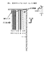
- FIG. 1 The structure of a conventional candle filter is shown in FIG.
- the structure consists of a wire mesh (40-60 mesh) 25, glass fiber ( ⁇ 0.8 ⁇ m) 24, glass fiber ( ⁇ 3 ⁇ m) 23, wire mesh strip (40-60 mesh) 22, glass fiber from the side through which steam containing mist passes. ( ⁇ 1.3 ⁇ m) 21, glass fiber ( ⁇ 0.8 ⁇ m) 20, cotton band (100 to 150 mesh) 19, wire mesh (40 to 60 mesh) 18 are wound around the punching plate 17. ing.
- the glass fiber ( ⁇ 0.8 ⁇ m) 24, the glass fiber ( ⁇ 3 ⁇ m) 23, the glass fiber ( ⁇ 1.3 ⁇ m) 21, and the glass fiber ( ⁇ 0.8 ⁇ m) 20 are arranged in the circumferential direction and the longitudinal direction.
- Table 2 shows the annual loss rate of rhodium from the cumulative amount of rhodium charged into the reactor for one year and the cumulative amount of loss calculated from the rhodium analysis results in the product aldehyde for one year. It is a thing. As a result, it was found that the rhodium loss rate in the reactor reached 4% in one year. In addition, one year (360 days) after the operation, the operation was stopped and the candle filter was confirmed. As a result, the glass fiber was slipped off. It was speculated that the adhesive used for joining the glass fibers deteriorated due to the erosion of the reaction product, and because the arrangement was poor, the fastening by the fastening band was insufficient, and it was dropped due to the weight of the recovered mist.
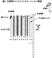
- Example 1 The structure of the candle filter of the present invention is shown in FIG.
- the structure consists of a wire mesh (40 to 60 mesh) 25, a wire mesh band (40 to 60 mesh) 29, a glass fiber ( ⁇ 0.8 ⁇ m) 24, a wire mesh band (40 to 60 mesh) 28 from the side through which steam containing mist passes.
- Glass fiber ( ⁇ 3 ⁇ m) 27, wire mesh band (40-60 mesh) 26, glass fiber ( ⁇ 3 ⁇ m) 23, wire mesh band (40-60 mesh) 22, glass fiber ( ⁇ 1.3 ⁇ m) 21, glass fiber ( ⁇ 0.8 ⁇ m) ) 20, cotton belt (100 to 150 mesh) 19, wire mesh (40 to 60 mesh) 18, 12 kinds of members are wound around the punching plate 17.
- the glass fibers are not bonded by an adhesive, and are attached by the method and arrangement shown in FIGS.
- the glass fiber layer is overlapped and wound as shown in FIGS. 7 and 8 and is not provided with an adhesive joint. Further, as shown in FIGS. 4 and 9, a wire mesh band is attached to the glass fiber layer, and the wire mesh band is wound in a spiral shape to prevent slipping off.
- Table 3 shows the annual loss rate of rhodium from the cumulative amount of rhodium charged into the reactor for one year and the cumulative amount of loss calculated from the rhodium analysis results in the produced aldehyde for one year. It is a thing. As a result, the rhodium loss rate in the reactor in the first year was 0.64%, and the loss rate in the second year was also 0.56%, and the rhodium loss was almost completely suppressed. The loss rate for two years was 1.08%, which was a significant improvement compared to using a conventional mist separator. Moreover, even if two years (730 days) have passed since the operation, no slipping of the glass fiber was confirmed, and it was found that the effect brought about by the modification of the candle filter was very large.
- Example 2 Normal continuous operation was performed for 2 years in the same manner as in Example 1 except that the conventional mist separator was used in the first year and the operation was continued by replacing the improved mist separator of the present invention in the second year. The results are shown in Table 4.
- the present invention is industrially used in 90% or more when propylene is used as an olefin raw material.
- Normal butyraldehyde and isobutyl aldehyde are produced in a 10: 1 ratio from the hydroformylation reaction of propylene.
- the following derivatives are mass-produced from normal butyraldehyde.
- Product name Use Butyl acrylate Polymer raw material 2-ethylhexyl acrylate Polymer raw material Normal butyl acetate
- Solvent Ethylene glycol monobutyl ether Solvent Normal Butanol Solvent Di (2-ethylhexyl) phthalate Plasticizer
Landscapes
- Chemical & Material Sciences (AREA)
- Organic Chemistry (AREA)
- Chemical Kinetics & Catalysis (AREA)
- Filtering Materials (AREA)
- Organic Low-Molecular-Weight Compounds And Preparation Thereof (AREA)
- Filtering Of Dispersed Particles In Gases (AREA)
- Low-Molecular Organic Synthesis Reactions Using Catalysts (AREA)
Description
本発明はオレフィンを一酸化炭素および水素(以下、一酸化炭素と水素との混合物を合成ガスとする。)とでロジウム-リン化合物錯体の存在においてヒドロホルミル化して、アルデヒド類を製造するプロセスにおいて、高価なロジウム触媒の損失をほぼ完全にゼロに抑えるために、特別に改良したキャンドルフィルターを用いて、反応器からのロジウム触媒の損失を防止する方法に関する。
ロジウムは全世界で年間十数トンしか産出しない貴重でかつ高価な貴金属である。従って、ロジウムを使用する工業では、できるだけ長期間かつ損失を防止して利用することが肝要である。
ヒドロホルミル化プロセスは、有機溶剤中に溶解したロジウム-リン錯体触媒を保有するヒドロホルミル化反応器内に気体状オレフィンと合成ガスをフィードし、反応で生成するアルデヒドを未反応のオレフィンガスおよび合成ガスと共に蒸発させ、生成するアルデヒドを反応器から除去する。しかし、反応器からアルデヒドを蒸発させる際に、ロジウム触媒が粗アルデヒドのミストと共に同伴され損失する。そのため、かかる物理的な触媒の損失による反応の活性低下を生ずることがある。
ロジウム触媒を含むミストをほぼ完全に除去し、ロジウム触媒の損失を防止するために特別に工夫したミストセパレーターを反応器からの蒸気排出口に設置してある。(図1参照)。このミスト除去操作は、ヒドロホルミル化反応にてアルデヒド類を製造するプロセスにおいては反応と並ぶ重要な操作である。
ミスト除去操作は、分離に関する単位操作の中で非常に難しい操作である。また、文献や専門書に種々の方法・装置が紹介されているが実際に応用するとその通りに行かないことが多い(非特許文献1)。
通常、化学装置に用いられる汎用型のミストセパレーターは、サイクロン、デミスター、フィルターなど個々に単独で使われるケースが多いが、この方法ではヒドロホルミル化反応プロセスで要求される性能確保には対応困難であるため、ロジウム触媒を含むミストの分離は次に示すそれぞれの分離機能に特徴を持った装置を3段階に配し、ほぼ完全に除去できるように工夫してある。
第一段:サイクロンセパレーター、第二段:デミスター、および第三段:キャンドルフィルターであり、特に第三段のキャンドルフィルターの構造は、ほぼ完全に除去するために重要である。
通常、化学装置に用いられる汎用型のミストセパレーターは、サイクロン、デミスター、フィルターなど個々に単独で使われるケースが多いが、この方法ではヒドロホルミル化反応プロセスで要求される性能確保には対応困難であるため、ロジウム触媒を含むミストの分離は次に示すそれぞれの分離機能に特徴を持った装置を3段階に配し、ほぼ完全に除去できるように工夫してある。
第一段:サイクロンセパレーター、第二段:デミスター、および第三段:キャンドルフィルターであり、特に第三段のキャンドルフィルターの構造は、ほぼ完全に除去するために重要である。
ヒドロホルミル化プロセスのミストセパレーターに用いられたキャンドルフィルターは、ミスト除去のための部材の一部を接着剤で取り付けられているものが多く、蒸発してくる有機物で接着剤が劣化してグラスファイバーがずり落ち、ミスト分離機能が低下して、このミストの漏洩が物理的な触媒の損失を来たすことがあった。そのために、その都度ロジウム触媒を追加する必要性が生ずるという問題点があった。
大塚英二著 分離システム 上 4.7章 丸善(株) (1975)
アルデヒド類を製造するヒドロホルミル化反応プロセス(ロジウム-リン化合物錯体触媒使用)において、反応器から蒸発除去される製品アルデヒドに同伴されるロジウム触媒損失を防止するため、反応器出口に設けたミストセパレーターに、図2の如く強固な構造のキャンドルフィルターを取り付ける。
従来のキャンドルフィルターは、脆弱で、かつ内部に取り付けるグラスファイバーなども接着剤で接着されていた。その結果、長期連続運転の前半期にキャンドルフィルターの一部に破損をきたし、ロジウム触媒の損失を生じていた。
従来使用していたキャンドルフィルターの問題点を明確にし、これを解決するために強固な構造のキャンドルフィルターとする。
従来のキャンドルフィルターは、脆弱で、かつ内部に取り付けるグラスファイバーなども接着剤で接着されていた。その結果、長期連続運転の前半期にキャンドルフィルターの一部に破損をきたし、ロジウム触媒の損失を生じていた。
従来使用していたキャンドルフィルターの問題点を明確にし、これを解決するために強固な構造のキャンドルフィルターとする。
上記課題を解決するために、以下に記載の項目を実施すれば、アルデヒド類を製造するヒドロホルミル化反応プロセス(ロジウム-リン化合物錯体触媒使用)において、反応器から蒸発除去されるアルデヒドに同伴されるロジウム触媒の損失を防止でき、2年間以上の長期連続運転が可能となる。
(1) アルデヒド類を製造するヒドロホルミル化反応プロセスにおいて、反応器出口に設けたミスト除去のための部材取り付けに接着剤を用いず、部材同士をオーバーラップさせ、金網帯で束ね、二年間以上の連続運転に耐えうる構造のキャンドルフィルターを取り付けることによってロジウム触媒の損失を防止する方法。
(2) キャンドルフィルターが、ミストを含む蒸気が通過する側から、金網、金網帯とグラスファイバーとの組み合わせを3組から7組、コットン帯、金網、パンチングプレートの順であり、合計で12個から24個からなる部材を取り付けた構造である(1)に記載のロジウム触媒の損失を防止する方法。
(3) キャンドルフィルターの部材の接合に、金網帯とグラスファイバーとの組み合わせで強固に本体に取り付けて、通過する蒸気の力に耐えうる強度を保持し、グラスファイバーのずり落ちを防止する(1)または(2)に記載のロジウム触媒の損失を防止する方法。
(4) ミストセパレーターで、生成アルデヒド中のロジウムの濃度を5重量ppb以下にすることができるキャンドルフィルターを用いる(1)から(3)のいずれか1項に記載のロジウム触媒の損失を防止する方法。
本発明は、オレフィンを一酸化炭素および水素でロジウム-リン化合物錯体の存在において、ヒドロホルミル化してアルデヒド類を製造するプロセスにおいて、ミストセパレーターのキャンドルフィルターを改良し、反応器からのロジウム触媒の損失を防止する方法に関する。本発明によれば、ロジウム触媒の年間ロス量を極微量にでき、かつ、それを維持したまま2年間の連続運転が可能となるため、ロジウム触媒のコストを抑えることができる。
以下、本発明を実施の形態に即して詳細に説明する。
ヒドロホルミル化反応プロセスの連続運転において、反応器からストリッピングされる蒸気に含まれるミストの量が多いとロジウム触媒の損失を生ずる。
このミストの量をできる限りゼロに近づけることができるキャンドルフィルターを発明することによりこの問題を解決できることを見出した。
ヒドロホルミル化反応プロセスの連続運転において、反応器からストリッピングされる蒸気に含まれるミストの量が多いとロジウム触媒の損失を生ずる。
このミストの量をできる限りゼロに近づけることができるキャンドルフィルターを発明することによりこの問題を解決できることを見出した。
(問題箇所の特定化)
本発明は、ロジウム触媒の損失に関するものである。
即ち、オレフィンを一酸化炭素および水素でロジウム-リン化合物錯体の存在においてヒドロホルミル化して、アルデヒド類を製造するプロセスにおいて、反応器から蒸発除去される気体中のアルデヒドのミストを除去するため、ミストセパレーターのキャンドルフィルターを改良し、反応器からのロジウム触媒の損失を防止する方法に関する。
従来法のキャンドルフィルターを用いた際は、運転開始後の生成アルデヒド中のロジウム濃度は、5重量ppb以下であった。しかし、運転開始後6ヶ月で、5重量ppbを超え、その後は50~60重量ppbに上昇し、12月後には100重量ppbに達した。
運転停止後、キャンドルフィルターの状況をチェックしたところ、グラスファイバーがずり落ちていることがわかった。
アルデヒドのミスト除去のためのキャンドルフィルターは、図1に示す反応系のミストセパレーター4に取り付けられる。ミストは、セパレーターのサイクロンセパレーター部で大部分のミストが除去される。大部分のミストを分離されたアルデヒド類の蒸気を含む気体はデミスターで更にミストを除かれ、残存する極少量のミストはキャンドルフィルターでほぼ完全に除去されるが、運転時間の経過と共にミストによる自重の増加に加えて、接着剤で接合していたグラスファイバーが劣化し、ずり落ちが発生することが判明した。このずれ落ちを防止し、更に強固な構造にして、ロジウム触媒損失防止対策を実施した。
本発明は、ロジウム触媒の損失に関するものである。
即ち、オレフィンを一酸化炭素および水素でロジウム-リン化合物錯体の存在においてヒドロホルミル化して、アルデヒド類を製造するプロセスにおいて、反応器から蒸発除去される気体中のアルデヒドのミストを除去するため、ミストセパレーターのキャンドルフィルターを改良し、反応器からのロジウム触媒の損失を防止する方法に関する。
従来法のキャンドルフィルターを用いた際は、運転開始後の生成アルデヒド中のロジウム濃度は、5重量ppb以下であった。しかし、運転開始後6ヶ月で、5重量ppbを超え、その後は50~60重量ppbに上昇し、12月後には100重量ppbに達した。
運転停止後、キャンドルフィルターの状況をチェックしたところ、グラスファイバーがずり落ちていることがわかった。
アルデヒドのミスト除去のためのキャンドルフィルターは、図1に示す反応系のミストセパレーター4に取り付けられる。ミストは、セパレーターのサイクロンセパレーター部で大部分のミストが除去される。大部分のミストを分離されたアルデヒド類の蒸気を含む気体はデミスターで更にミストを除かれ、残存する極少量のミストはキャンドルフィルターでほぼ完全に除去されるが、運転時間の経過と共にミストによる自重の増加に加えて、接着剤で接合していたグラスファイバーが劣化し、ずり落ちが発生することが判明した。このずれ落ちを防止し、更に強固な構造にして、ロジウム触媒損失防止対策を実施した。
(概略フローシート)
本発明の反応系における機器設置のフローシートを図1に示す。オレフィンとしてプロピレンを用いる場合を例示した。
本発明の反応系における機器設置のフローシートを図1に示す。オレフィンとしてプロピレンを用いる場合を例示した。
図1について説明する。
原料のプロピレンおよび合成ガスは、精製塔1および2で、それぞれ触媒毒を除去される。精製されたプロピレンは、反応系の反応器3にフィードされる。反応生成物のブチルアルデヒドは、未反応ガスと一緒に反応器から蒸発し、ミストセパレーター4で蒸発物中に含まれる極微量のロジウム触媒を分離して、反応系の反応器に戻される。蒸発したブチルアルデヒド、未反応プロピレン、合成ガスの混合物は、凝縮器5で冷却される。更に、気液分離器6で液体ブチルアルデヒドと気体の未反応プロピレンと合成ガスに分離される。気体のプロピレン、合成ガスは、循環ブロアー7を経て反応系に循環される。凝縮したブチルアルデヒドは、向流塔8の塔頂部にフィードし、反応系に供給される精製合成ガスの所定量を向流塔8の下部から供給し、ブチルアルデヒドに溶解しているプロピレンを除去する。向流塔8の下部から粗ブチルアルデヒドが抜き出される。
原料のプロピレンおよび合成ガスは、精製塔1および2で、それぞれ触媒毒を除去される。精製されたプロピレンは、反応系の反応器3にフィードされる。反応生成物のブチルアルデヒドは、未反応ガスと一緒に反応器から蒸発し、ミストセパレーター4で蒸発物中に含まれる極微量のロジウム触媒を分離して、反応系の反応器に戻される。蒸発したブチルアルデヒド、未反応プロピレン、合成ガスの混合物は、凝縮器5で冷却される。更に、気液分離器6で液体ブチルアルデヒドと気体の未反応プロピレンと合成ガスに分離される。気体のプロピレン、合成ガスは、循環ブロアー7を経て反応系に循環される。凝縮したブチルアルデヒドは、向流塔8の塔頂部にフィードし、反応系に供給される精製合成ガスの所定量を向流塔8の下部から供給し、ブチルアルデヒドに溶解しているプロピレンを除去する。向流塔8の下部から粗ブチルアルデヒドが抜き出される。
(ミストセパレーター概略図)
本発明のミストセパレーターにおける機器の配列とガスの流れを図2に示す。
本発明のミストセパレーターにおける機器の配列とガスの流れを図2に示す。
図2について説明する
反応器3で生成した反応生成ガスは、反応器3の上部から管路12によりミストセパレータ4の第1段分離器(サイクロンセパレータ9)に導入される。サイクロンセパレータ9で反応生成ガスに含まれる大部分のミストは除去され、ミストは管路13より管路14を経由して反応器3へ戻る。大部分のミストを除かれた反応生成ガスは、第2段分離器(デミスター10)により更にミストを分離する。ミストは管路16より管路14を経由して反応器3に戻る。
デミスター10を通過した反応生成ガスは第3段分離器(キャンドルフィルター11)に導入され更に極微量の残存ミストを除去する。ミストは管路15より管路14を経由して反応器3へ戻る。
ミストを除去した反応生成ガスは、同時にロジウム触媒もほぼ完全に分離され、ミストセパレータ4の上部ガス出口より、次工程に導入される。
反応器3で生成した反応生成ガスは、反応器3の上部から管路12によりミストセパレータ4の第1段分離器(サイクロンセパレータ9)に導入される。サイクロンセパレータ9で反応生成ガスに含まれる大部分のミストは除去され、ミストは管路13より管路14を経由して反応器3へ戻る。大部分のミストを除かれた反応生成ガスは、第2段分離器(デミスター10)により更にミストを分離する。ミストは管路16より管路14を経由して反応器3に戻る。
デミスター10を通過した反応生成ガスは第3段分離器(キャンドルフィルター11)に導入され更に極微量の残存ミストを除去する。ミストは管路15より管路14を経由して反応器3へ戻る。
ミストを除去した反応生成ガスは、同時にロジウム触媒もほぼ完全に分離され、ミストセパレータ4の上部ガス出口より、次工程に導入される。
(従来のキャンドルフィルターエレメント略図)
従来のキャンドルフィルター部材の材質と配列構成を図3に示す。
従来のキャンドルフィルター部材の材質と配列構成を図3に示す。
図3について説明する
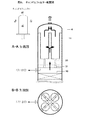
ロジウム触媒損失が生じたキャンドルフィルター部材の配列と構成は、ミストを含む蒸気が通過する側から、金網(40~60メッシュ)25、グラスファイバー(φ0.8μm)24、グラスファイバー(φ3μm)23、金網帯(40~60メッシュ)22、グラスファイバー(φ1.3μm)21、グラスファイバー(φ0.8μm)20、コットン帯(100~150メッシュ)19、金網(40~60メッシュ)18、パンチングプレート17の9種類の部材を取り付けた構造である。
グラスファイバー(φ0.8μm)24、グラスファイバー(φ3μm)23、グラスファイバー(φμm1.3)21、グラスファイバー(φ0.8μm)20は、円周方向および長手方向に接合部を有し、接合には接着剤を用いていたために、反応生成物により劣化し、ずり落ち脱落への原因となっていた。更にグラスファイバー同士の配列で、締め付けバンドによる締め付け力不足を生じさせ、ずり落ちの要因を増長していた。
ロジウム触媒損失が生じたキャンドルフィルター部材の配列と構成は、ミストを含む蒸気が通過する側から、金網(40~60メッシュ)25、グラスファイバー(φ0.8μm)24、グラスファイバー(φ3μm)23、金網帯(40~60メッシュ)22、グラスファイバー(φ1.3μm)21、グラスファイバー(φ0.8μm)20、コットン帯(100~150メッシュ)19、金網(40~60メッシュ)18、パンチングプレート17の9種類の部材を取り付けた構造である。
グラスファイバー(φ0.8μm)24、グラスファイバー(φ3μm)23、グラスファイバー(φμm1.3)21、グラスファイバー(φ0.8μm)20は、円周方向および長手方向に接合部を有し、接合には接着剤を用いていたために、反応生成物により劣化し、ずり落ち脱落への原因となっていた。更にグラスファイバー同士の配列で、締め付けバンドによる締め付け力不足を生じさせ、ずり落ちの要因を増長していた。
(本発明のキャンドルフィルターエレメント略図)
本発明のキャンドルフィルター部材の材質と配列構成を図4に示す。
本発明のキャンドルフィルター部材の材質と配列構成を図4に示す。
図4について説明する
触媒損失防止のための好適なキャンドルフィルター部材の配列と構成は、ミストを含む蒸気に接する側から金網(40~60メッシュ)25、金網帯(40~60メッシュ)29、グラスファイバー(φ0.8μm)24、金網帯(40~60メッシュ)28、グラスファイバー(φ3μm)27、金網帯(40~60メッシュ)26、グラスファイバー(φ3μm)23、金網帯(40~60メッシュ)22、グラスファイバー(φ1.3μm)21、グラスファイバー(φ0.8μm)20、コットン帯(100~150メッシュ)19、金網(40~60メッシュ)18、パンチングプレート17の13個の部材を取り付けた構造で、これを用いることでロジウム-リン錯体の損失を防止する。
触媒損失防止のための好適なキャンドルフィルター部材の配列と構成は、ミストを含む蒸気に接する側から金網(40~60メッシュ)25、金網帯(40~60メッシュ)29、グラスファイバー(φ0.8μm)24、金網帯(40~60メッシュ)28、グラスファイバー(φ3μm)27、金網帯(40~60メッシュ)26、グラスファイバー(φ3μm)23、金網帯(40~60メッシュ)22、グラスファイバー(φ1.3μm)21、グラスファイバー(φ0.8μm)20、コットン帯(100~150メッシュ)19、金網(40~60メッシュ)18、パンチングプレート17の13個の部材を取り付けた構造で、これを用いることでロジウム-リン錯体の損失を防止する。
(従来のグラスファイバー接合部(接着部)略図)
従来のキャンドルフィルター部材のグラスファイバー接着部を図5に示す。
従来のキャンドルフィルター部材のグラスファイバー接着部を図5に示す。
図5について説明する
キャンドルフィルターに用いたグラスファイバー23は、それぞれ円周方向と長手方向の接合部を接着剤で張り合わせ一体ものとして巻きつけ使用していた。
キャンドルフィルターに用いたグラスファイバー23は、それぞれ円周方向と長手方向の接合部を接着剤で張り合わせ一体ものとして巻きつけ使用していた。
(本発明のキャンドルフィルター配置図)
本発明のキャンドルフィルターの設置状況を図6に示す。
本発明のキャンドルフィルターの設置状況を図6に示す。
図6について説明する。
ミストセパレーター4の第2段目分離器(デミスター10)を通過したミストを含むガスは、第3段目分離器(キャンドルフィルター11)の外側から内側へと流れ、この間にミストを除かれ、ミストはシールパイプ30、シールパン31を経由してミスト出口へ導かれる。ミストを除かれたガスは、ミストセパレータ4の上部より次工程へ移送される。これら4本のキャンドルフィルター11はシールパイプ30、シールポット31によりシールされ、逆流の防止と差圧増加時の安全対策も兼ね備えている。
ミストセパレーター4の第2段目分離器(デミスター10)を通過したミストを含むガスは、第3段目分離器(キャンドルフィルター11)の外側から内側へと流れ、この間にミストを除かれ、ミストはシールパイプ30、シールパン31を経由してミスト出口へ導かれる。ミストを除かれたガスは、ミストセパレータ4の上部より次工程へ移送される。これら4本のキャンドルフィルター11はシールパイプ30、シールポット31によりシールされ、逆流の防止と差圧増加時の安全対策も兼ね備えている。
(本発明のグラスファイバーの取り付け方(平面図))
本発明のキャンドルフィルター11のグラスファイバー27の取り付け方を図7に示す。
本発明のキャンドルフィルター11のグラスファイバー27の取り付け方を図7に示す。
図7について説明する。
本発明のグラスファイバー27の接合は、オーバーラップ部を重ならない様にするために、一巻き目と二巻き目は接合部を90度ずらし、順次オーバーラップ部の位置を90~180度の範囲でずらしてガスのショートパスを防止する。
従来のグラスファイバー23は、接着剤を用いて接合したために、接着剤の劣化により接合部が剥がれ、ずり落ちを誘発した。
本発明のグラスファイバー27の接合は、オーバーラップ部を重ならない様にするために、一巻き目と二巻き目は接合部を90度ずらし、順次オーバーラップ部の位置を90~180度の範囲でずらしてガスのショートパスを防止する。
従来のグラスファイバー23は、接着剤を用いて接合したために、接着剤の劣化により接合部が剥がれ、ずり落ちを誘発した。
(本発明のグラスファイバー巻き付け略図(オーバーラップ))
本発明のキャンドルフィルター11のグラスファイバー27の巻き付け方は図8に示したオーバーラップと図4に示した針金により強固に緊縛する。
尚、上述のオーバーラップは全てのグラスファイバーに適用する。
本発明のキャンドルフィルター11のグラスファイバー27の巻き付け方は図8に示したオーバーラップと図4に示した針金により強固に緊縛する。
尚、上述のオーバーラップは全てのグラスファイバーに適用する。
図8について説明する。
本発明のグラスファイバー27の巻き付け方は、オーバラップ部を、一巻毎に90度ずらす様に巻きつけ、ガスのショートパス防止に改良を加えた。本図は一層目と二層目のオーバーラップ部を示した。ずり落ち防止には図4に示す針金で強固に緊縛する。
本発明のグラスファイバー27の巻き付け方は、オーバラップ部を、一巻毎に90度ずらす様に巻きつけ、ガスのショートパス防止に改良を加えた。本図は一層目と二層目のオーバーラップ部を示した。ずり落ち防止には図4に示す針金で強固に緊縛する。
(本発明のズリ落ち防止用金網巻き付け略図)
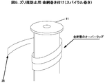
本発明のキャンドルフィルター11のズリ落ち防止用金網の巻き方を図9に示す金網の巻き方と図4に示した針金及び締め付けバンドにて強固に取り付ける。
尚、上述の巻き方は全ての金網帯に適用する。
本発明のキャンドルフィルター11のズリ落ち防止用金網の巻き方を図9に示す金網の巻き方と図4に示した針金及び締め付けバンドにて強固に取り付ける。
尚、上述の巻き方は全ての金網帯に適用する。
図9について説明する。
本発明のズリ落ち防止用の金網帯28はオーバーラップさせながらスパイラル状に巻き付ける。これに加え図4に示した針金による緊縛と締め付けバンドによって強固に取り付け、ズリ落ちを防止する。
本発明のズリ落ち防止用の金網帯28はオーバーラップさせながらスパイラル状に巻き付ける。これに加え図4に示した針金による緊縛と締め付けバンドによって強固に取り付け、ズリ落ちを防止する。
以下、本発明に関わる反応器からのロジウム触媒の損失を防止する方法を実施例に基づいてさらに詳しく説明する。しかしながら本発明はこれらの実施例に制限されるものではない。
[比較例1]
従来のキャンドルフィルターの構造を図3に示す。その構造は、ミストを含む蒸気が通過する側から金網(40~60メッシュ)25、グラスファイバー(φ0.8μm)24、グラスファイバー(φ3μm)23、金網帯(40~60メッシュ)22、グラスファイバー(φ1.3μm)21、グラスファイバー(φ0.8μm)20、コットン帯(100~150メッシュ)19、金網(40~60メッシュ)18の8種類の部材をパンチングプレート17に巻きつけた構成となっている。図5および7に示すようにグラスファイバー(φ0.8μm)24、グラスファイバー(φ3μm)23、グラスファイバー(φ1.3μm)21、グラスファイバー(φ0.8μm)20は、円周方向および長手方向に接合部を有し、接合には接着剤を用いている。
従来のキャンドルフィルターを設置した設備で通常運転を開始した。運転中は一定期間毎に反応器内の液を抜き出し、反応液中のロジウム濃度および生成アルデヒド中のロジウム濃度を分析した。それらの分析結果を表1に示す。60日毎に所定量のロジウムを追加しているため、反応液中のロジウム濃度は初期250重量ppmから徐々に増加し、1年後には約430重量ppmに達する。従来のキャンドルフィルターを使用した場合、生成アルデヒド中のロジウム濃度は初期2重量ppbしか検出されなかったものが、1年後には95重量ppbとなっていた。
表2は反応器に投入されたロジウムの1年間の累積量と、生成アルデヒド中のロジウム分析結果より算出したロス量の1年分の積算量とから、ロジウムの1年当たりのロス率を求めたものである。その結果、1年で反応器内のロジウムロス率は4%までに達することが分かった。
また、運転から1年(360日)経過後、運転を停止してキャンドルフィルターを確認したところ、グラスファイバーがずり落ちていた。グラスファイバー同士の接合に用いた接着剤が反応生成物の浸食により劣化し、また配列が悪いために、締め付けバンドによる締め付けが不十分となり、回収ミストの自重により脱落したものと推測された。
従来のキャンドルフィルターの構造を図3に示す。その構造は、ミストを含む蒸気が通過する側から金網(40~60メッシュ)25、グラスファイバー(φ0.8μm)24、グラスファイバー(φ3μm)23、金網帯(40~60メッシュ)22、グラスファイバー(φ1.3μm)21、グラスファイバー(φ0.8μm)20、コットン帯(100~150メッシュ)19、金網(40~60メッシュ)18の8種類の部材をパンチングプレート17に巻きつけた構成となっている。図5および7に示すようにグラスファイバー(φ0.8μm)24、グラスファイバー(φ3μm)23、グラスファイバー(φ1.3μm)21、グラスファイバー(φ0.8μm)20は、円周方向および長手方向に接合部を有し、接合には接着剤を用いている。
従来のキャンドルフィルターを設置した設備で通常運転を開始した。運転中は一定期間毎に反応器内の液を抜き出し、反応液中のロジウム濃度および生成アルデヒド中のロジウム濃度を分析した。それらの分析結果を表1に示す。60日毎に所定量のロジウムを追加しているため、反応液中のロジウム濃度は初期250重量ppmから徐々に増加し、1年後には約430重量ppmに達する。従来のキャンドルフィルターを使用した場合、生成アルデヒド中のロジウム濃度は初期2重量ppbしか検出されなかったものが、1年後には95重量ppbとなっていた。
表2は反応器に投入されたロジウムの1年間の累積量と、生成アルデヒド中のロジウム分析結果より算出したロス量の1年分の積算量とから、ロジウムの1年当たりのロス率を求めたものである。その結果、1年で反応器内のロジウムロス率は4%までに達することが分かった。
また、運転から1年(360日)経過後、運転を停止してキャンドルフィルターを確認したところ、グラスファイバーがずり落ちていた。グラスファイバー同士の接合に用いた接着剤が反応生成物の浸食により劣化し、また配列が悪いために、締め付けバンドによる締め付けが不十分となり、回収ミストの自重により脱落したものと推測された。
(アルデヒド中のロジウム濃度の分析方法)
分析方法;原子吸光分析法を基本とする。
試料をグラファイト製の電気炉で加熱して原子化(ガス化)し、ロジウム固有の波長の光の吸収量から試料中のロジウム含有量を求める方法である。(ファーネス法)
測定装置は、原子吸光分析装置(サーモエレクトロン社製 SOLAAR M6 mkII)を使用した。検出限界は1重量ppbである。
必要であればサンプル液を反応溶媒ブチルアルデヒドで適切な倍率に希釈し、測定装置に掛けて測定する。
分析方法;原子吸光分析法を基本とする。
試料をグラファイト製の電気炉で加熱して原子化(ガス化)し、ロジウム固有の波長の光の吸収量から試料中のロジウム含有量を求める方法である。(ファーネス法)
測定装置は、原子吸光分析装置(サーモエレクトロン社製 SOLAAR M6 mkII)を使用した。検出限界は1重量ppbである。
必要であればサンプル液を反応溶媒ブチルアルデヒドで適切な倍率に希釈し、測定装置に掛けて測定する。
[実施例1]
本発明のキャンドルフィルターの構造を図4に示す。その構造は、ミストを含む蒸気が通過する側から金網(40~60メッシュ)25、金網帯(40~60メッシュ)29、グラスファイバー(φ0.8μm)24、金網帯(40~60メッシュ)28、グラスファイバー(φ3μm)27、金網帯(40~60メッシュ)26、グラスファイバー(φ3μm)23、金網帯(40~60メッシュ)22、グラスファイバー(φ1.3μm)21、グラスファイバー(φ0.8μm)20、コットン帯(100~150メッシュ)19、金網(40~60メッシュ)18の12種類の部材をパンチングプレート17に巻きつけた構成となっている。グラスファイバーは接着剤による接合をせず、図7から9に示した方法、配列で取り付けている。グラスファイバー層は図7および8に示すようにオーバラップして巻き、接着剤による接合部を設けていない。さらに図4および9に示すようにグラスファイバー層に金網帯を付け、金網帯はスパイラル状に巻き、ずり落ち防止を図っている。
本発明のキャンドルフィルターの構造を図4に示す。その構造は、ミストを含む蒸気が通過する側から金網(40~60メッシュ)25、金網帯(40~60メッシュ)29、グラスファイバー(φ0.8μm)24、金網帯(40~60メッシュ)28、グラスファイバー(φ3μm)27、金網帯(40~60メッシュ)26、グラスファイバー(φ3μm)23、金網帯(40~60メッシュ)22、グラスファイバー(φ1.3μm)21、グラスファイバー(φ0.8μm)20、コットン帯(100~150メッシュ)19、金網(40~60メッシュ)18の12種類の部材をパンチングプレート17に巻きつけた構成となっている。グラスファイバーは接着剤による接合をせず、図7から9に示した方法、配列で取り付けている。グラスファイバー層は図7および8に示すようにオーバラップして巻き、接着剤による接合部を設けていない。さらに図4および9に示すようにグラスファイバー層に金網帯を付け、金網帯はスパイラル状に巻き、ずり落ち防止を図っている。
本発明のキャンドルフィルターを設置した設備で通常運転を開始した。運転中は一定期間毎に反応器内の液を抜き出し、反応液中のロジウム濃度および生成アルデヒド中のロジウム濃度を分析した。それらの分析結果を表1に示す。60日毎に所定量のロジウムを追加しているため、反応液中のロジウム濃度は初期250重量ppmから徐々に増加し、1年後には約430重量ppmに達する。本発明のキャンドルフィルターを使用した場合、生成アルデヒド中のロジウム濃度は初期に2重量ppbしか検出されず、しかも2年後もその濃度は3重量ppbとほとんど増加が見られなかった。
表3は反応器に投入されたロジウムの1年間の累積量と、生成アルデヒド中のロジウム分析結果より算出したロス量の1年分の積算量とから、ロジウムの1年当たりのロス率を求めたものである。その結果、1年目の反応器内のロジウムロス率は0.64%であり、2年目のロス率も0.56%とロジウムの損失をほぼ完全に抑えることができた。2年間のロス率は1.08%であり、従来型のミストセパレーターを使用した場合に比べ、大幅に改善された。
また、運転から2年(730日)経過しても、グラスファイバーのずり落ちは確認できず、キャンドルフィルターの改造がもたらす効果が非常に大きいことがわかった。
表3は反応器に投入されたロジウムの1年間の累積量と、生成アルデヒド中のロジウム分析結果より算出したロス量の1年分の積算量とから、ロジウムの1年当たりのロス率を求めたものである。その結果、1年目の反応器内のロジウムロス率は0.64%であり、2年目のロス率も0.56%とロジウムの損失をほぼ完全に抑えることができた。2年間のロス率は1.08%であり、従来型のミストセパレーターを使用した場合に比べ、大幅に改善された。
また、運転から2年(730日)経過しても、グラスファイバーのずり落ちは確認できず、キャンドルフィルターの改造がもたらす効果が非常に大きいことがわかった。
表1 反応液中と生成アルデヒド液中のロジウム濃度の推移

表2 従来のミストセパレーターでのロジウム触媒ロス率

表3 2年連続運転における本発明のミストセパレーターでのロジウム触媒ロス率

[実施例2]
1年目は従来のミストセパレーターを使用し、2年目に本発明の改良ミストセパレーターに交換して運転を継続した以外は、実施例1と同様に通常の連続運転を2年間行った。
その結果を表4に示した。
1年目は従来のミストセパレーターを使用し、2年目に本発明の改良ミストセパレーターに交換して運転を継続した以外は、実施例1と同様に通常の連続運転を2年間行った。
その結果を表4に示した。
表4 2年連続運転における本発明のミストセパレーターの効果

発明品のフィルターを使用した場合、実施例1、2ともに1年間のロジウムロス率は0.5%台であり、その効果は歴然である。
従来のフィルターでは、構造上の欠陥から、反応器より蒸発する生成アルデヒドに同伴されるロジウムのロス率が1年間で4%に達していた。しかし、本発明による改良型のキャンドルフィルターを用いることにより年間0.5~0.6%に抑えることができる。ロジウムのミスト同伴ロスの抑制量は年間1kg以上になり、その経済効果は大きい。
発明品のフィルターを使用した場合、実施例1、2ともに1年間のロジウムロス率は0.5%台であり、その効果は歴然である。
従来のフィルターでは、構造上の欠陥から、反応器より蒸発する生成アルデヒドに同伴されるロジウムのロス率が1年間で4%に達していた。しかし、本発明による改良型のキャンドルフィルターを用いることにより年間0.5~0.6%に抑えることができる。ロジウムのミスト同伴ロスの抑制量は年間1kg以上になり、その経済効果は大きい。
本発明が工業的に用いられるのは、オレフィン原料としてプロピレンを用いる場合が90%以上である。プロピレンのヒドロホルミル化反応から10:1の比率でノルマルブチルアルデヒドとイソブチルアルデヒトが製造される。ノルマルブチルアルデヒドからは、下記の誘導体が製品として量産されている。
製品名 用途
アクリル酸ブチル ポリマー原料
アクリル酸2-エチルヘキシル ポリマー原料
酢酸ノルマルブチル 溶剤
エチレングリコールモノブチルエーテル 溶剤
ノルマルブタノール 溶剤
ジ(2-エチルヘキシル)フタレート 可塑剤
製品名 用途
アクリル酸ブチル ポリマー原料
アクリル酸2-エチルヘキシル ポリマー原料
酢酸ノルマルブチル 溶剤
エチレングリコールモノブチルエーテル 溶剤
ノルマルブタノール 溶剤
ジ(2-エチルヘキシル)フタレート 可塑剤
また、イソブチルアルデヒドからは、下記の誘導体が製品として量産されている。
製品名 用途
イソブタノール 溶剤
2,2,4-トリメチル-1,3-ペンタンジオールモノイソブチレート 造膜助剤
これらの製品は、工業的に重要な製品である。これら製品の原料となるブチルアルデヒドの製造に本発明は利用される。
製品名 用途
イソブタノール 溶剤
2,2,4-トリメチル-1,3-ペンタンジオールモノイソブチレート 造膜助剤
これらの製品は、工業的に重要な製品である。これら製品の原料となるブチルアルデヒドの製造に本発明は利用される。
1 精製塔
2 精製塔
3 反応器
4 ミストセパレーター
5 凝縮器
6 気液分離器
7 循環ブロワー
8 向流塔
9 サイクロンセパレーター
10 デミスター
11 キャンドルフィルター
12 管路
13 管路
14 管路
15 管路
16 管路
17 パンチングプレート
18 金網(40~60メッシュ)
19 コットン帯(100~150メッシュ)
20 グラスファイバー(φ0.8μm)
21 グラスファイバー(φ1.3μm)
22 金網帯(40~60メッシュ)
23 グラスファイバー(φ3.0μm)
24 グラスファイバー(φ0.8μm)
25 金網(40~60メッシュ)
26 金網帯(40~60メッシュ)
27 グラスファイバー(φ3μm)
28 金網帯(40~60メッシュ)
29 金網帯(40~60メッシュ)
30 シールパイプ
31 シールポット
2 精製塔
3 反応器
4 ミストセパレーター
5 凝縮器
6 気液分離器
7 循環ブロワー
8 向流塔
9 サイクロンセパレーター
10 デミスター
11 キャンドルフィルター
12 管路
13 管路
14 管路
15 管路
16 管路
17 パンチングプレート
18 金網(40~60メッシュ)
19 コットン帯(100~150メッシュ)
20 グラスファイバー(φ0.8μm)
21 グラスファイバー(φ1.3μm)
22 金網帯(40~60メッシュ)
23 グラスファイバー(φ3.0μm)
24 グラスファイバー(φ0.8μm)
25 金網(40~60メッシュ)
26 金網帯(40~60メッシュ)
27 グラスファイバー(φ3μm)
28 金網帯(40~60メッシュ)
29 金網帯(40~60メッシュ)
30 シールパイプ
31 シールポット
Claims (4)
- アルデヒド類を製造するヒドロホルミル化反応プロセスにおいて、反応器出口に設けたミスト除去のための部材取り付けに接着剤を用いず、部材同士をオーバーラップさせ、金網帯で束ね、二年間以上の連続運転に耐えうる構造のキャンドルフィルターを取り付けることによってロジウム触媒の損失を防止する方法。
- キャンドルフィルターが、ミストを含む蒸気が通過する側から、金網、金網帯とグラスファイバーとの組み合わせを3組から7組、コットン帯、金網、パンチングプレートの順であり、合計で12個から24個からなる部材を取り付けた構造である請求項1に記載のロジウム触媒の損失を防止する方法。
- キャンドルフィルターの部材の接合に、金網帯とグラスファイバーとの組み合わせで本体に取り付けて、通過する蒸気の力に耐えうる強度を保持し、グラスファイバーのずり落ちを防止する請求項1または2に記載のロジウム触媒の損失を防止する方法。
- ミストセパレーターにおいて、アルデヒド中のロジウムの濃度を5重量ppb以下にすることができるキャンドルフィルターを用いる請求項1から3のいずれか1項に記載のロジウム触媒の損失を防止する方法。
Priority Applications (2)
| Application Number | Priority Date | Filing Date | Title |
|---|---|---|---|
| CN201380036486.8A CN104428278B (zh) | 2012-07-10 | 2013-07-01 | 防止铑催化剂的损失的方法 |
| JP2014524743A JP6183364B2 (ja) | 2012-07-10 | 2013-07-01 | ヒドロホルミル化触媒損失防止法 |
Applications Claiming Priority (2)
| Application Number | Priority Date | Filing Date | Title |
|---|---|---|---|
| JP2012-154293 | 2012-07-10 | ||
| JP2012154293 | 2012-07-10 |
Publications (1)
| Publication Number | Publication Date |
|---|---|
| WO2014010451A1 true WO2014010451A1 (ja) | 2014-01-16 |
Family
ID=49915915
Family Applications (1)
| Application Number | Title | Priority Date | Filing Date |
|---|---|---|---|
| PCT/JP2013/068008 Ceased WO2014010451A1 (ja) | 2012-07-10 | 2013-07-01 | ヒドロホルミル化触媒損失防止法 |
Country Status (3)
| Country | Link |
|---|---|
| JP (1) | JP6183364B2 (ja) |
| CN (1) | CN104428278B (ja) |
| WO (1) | WO2014010451A1 (ja) |
Cited By (2)
| Publication number | Priority date | Publication date | Assignee | Title |
|---|---|---|---|---|
| WO2016030207A1 (de) * | 2014-08-29 | 2016-03-03 | Dürr Systems GmbH | Reinigungsvorrichtung, verwendung einer reinigungsvorrichtung und verfahren zum reinigen eines abgasstroms |
| JP2017521242A (ja) * | 2014-06-19 | 2017-08-03 | サビック グローバル テクノロジーズ ベスローテン フェンノートシャップ | 向上した均一触媒反応器システム |
Citations (2)
| Publication number | Priority date | Publication date | Assignee | Title |
|---|---|---|---|---|
| JPS6227007A (ja) * | 1985-07-18 | 1987-02-05 | アマフィルター メンブランテクニック ゲゼルシャフト ミット ベシュレンクテル ハフツンク | 巻付け膜キヤンドルフイルタ− |
| WO2010115511A1 (de) * | 2009-04-07 | 2010-10-14 | Oxea Gmbh | Verfahren zur aufarbeitung eines flüssigen hydroformylierungsaustrags |
Family Cites Families (5)
| Publication number | Priority date | Publication date | Assignee | Title |
|---|---|---|---|---|
| US4247486A (en) * | 1977-03-11 | 1981-01-27 | Union Carbide Corporation | Cyclic hydroformylation process |
| DE102008002187A1 (de) * | 2008-06-03 | 2009-12-10 | Evonik Oxeno Gmbh | Verfahren zur Herstellung von C5-Aldehydgemischen mit hohem n-Pentanalanteil |
| CN102115433B (zh) * | 2010-12-06 | 2013-09-11 | 淄博诺奥化工有限公司 | 一种乙烯低压羰基合成生产丙醛的方法 |
| CN202036884U (zh) * | 2011-03-12 | 2011-11-16 | 江苏新宏大集团有限公司 | 混装式纤维除雾器 |
| CN202128993U (zh) * | 2011-06-23 | 2012-02-01 | 上海闰铭精密技术有限公司 | 油雾收集器 |
-
2013
- 2013-07-01 JP JP2014524743A patent/JP6183364B2/ja active Active
- 2013-07-01 CN CN201380036486.8A patent/CN104428278B/zh active Active
- 2013-07-01 WO PCT/JP2013/068008 patent/WO2014010451A1/ja not_active Ceased
Patent Citations (2)
| Publication number | Priority date | Publication date | Assignee | Title |
|---|---|---|---|---|
| JPS6227007A (ja) * | 1985-07-18 | 1987-02-05 | アマフィルター メンブランテクニック ゲゼルシャフト ミット ベシュレンクテル ハフツンク | 巻付け膜キヤンドルフイルタ− |
| WO2010115511A1 (de) * | 2009-04-07 | 2010-10-14 | Oxea Gmbh | Verfahren zur aufarbeitung eines flüssigen hydroformylierungsaustrags |
Cited By (2)
| Publication number | Priority date | Publication date | Assignee | Title |
|---|---|---|---|---|
| JP2017521242A (ja) * | 2014-06-19 | 2017-08-03 | サビック グローバル テクノロジーズ ベスローテン フェンノートシャップ | 向上した均一触媒反応器システム |
| WO2016030207A1 (de) * | 2014-08-29 | 2016-03-03 | Dürr Systems GmbH | Reinigungsvorrichtung, verwendung einer reinigungsvorrichtung und verfahren zum reinigen eines abgasstroms |
Also Published As
| Publication number | Publication date |
|---|---|
| CN104428278B (zh) | 2017-03-08 |
| JPWO2014010451A1 (ja) | 2016-06-23 |
| JP6183364B2 (ja) | 2017-08-23 |
| CN104428278A (zh) | 2015-03-18 |
Similar Documents
| Publication | Publication Date | Title |
|---|---|---|
| EP2280920B1 (de) | Verfahren zur herstellung von c5-aldehydgemischen mit hohem n-pentanalanteil | |
| US8282899B2 (en) | Absorption method for recovering gas contaminants at high purity | |
| JP5386590B2 (ja) | メタノール−オレフィンプロセスのための吸収装置及び脱メタン装置 | |
| BR112015014628B8 (pt) | processo para produzir ácido acético, e, método para separar ou remover acetaldeído | |
| JP6183364B2 (ja) | ヒドロホルミル化触媒損失防止法 | |
| JP5676011B2 (ja) | Fccプロセス用の吸収体脱メタン塔 | |
| CN101381309A (zh) | 草酸二甲酯合成过程中双塔流程分离低浓度碳酸二甲酯的方法 | |
| US20180361319A1 (en) | Method for improved reactve monomer production with membrane filtration | |
| JP6592593B2 (ja) | フェノールの精製方法 | |
| CN101289359A (zh) | 利用离子液体从醚生产工艺的烯烃进料中除去乙腈的方法 | |
| JPS5827961B2 (ja) | 蒸留性混合物の精留方法 | |
| KR102580069B1 (ko) | 압력 변동 증류를 사용한 메탄올/메틸 메타크릴레이트 공비혼합물의 파괴 | |
| CN102781890A (zh) | 从烃物流除去含氧污染物的方法 | |
| KR102298467B1 (ko) | 코크스 오븐 가스 내의 나프탈렌의 감소 | |
| CN108713052B (zh) | 丙烷脱氢方法中废气与c3烃的分离 | |
| US8471088B2 (en) | Solvent quality control in extraction processes | |
| WO2013160420A1 (en) | Method for reducing organic impurities in waste water | |
| CN102884029B (zh) | 用于生产低含氧化合物的烯烃流的方法和设备 | |
| US9138658B2 (en) | Solvent quality control in extraction processes | |
| CN205974322U (zh) | 用于生产纯化的甲醇的设备 | |
| US10059651B2 (en) | Separation process | |
| IL199054A (en) | Method of purifying beta-phenylethyl alcohol | |
| RU2664800C2 (ru) | Способ регулирования тепла, включающий охлаждение расширением и рециркуляцию охлажденного газа | |
| EP2406203B1 (de) | Verfahren und vorrichtung zur verminderung von olefinverlusten bei der entfernung von kohlendioxid aus einem olefinstrom aus dehydrierungsreaktionen | |
| US8686212B2 (en) | Process for treatment of ethylene |
Legal Events
| Date | Code | Title | Description |
|---|---|---|---|
| 121 | Ep: the epo has been informed by wipo that ep was designated in this application |
Ref document number: 13816514 Country of ref document: EP Kind code of ref document: A1 |
|
| ENP | Entry into the national phase |
Ref document number: 2014524743 Country of ref document: JP Kind code of ref document: A |
|
| NENP | Non-entry into the national phase |
Ref country code: DE |
|
| 122 | Ep: pct application non-entry in european phase |
Ref document number: 13816514 Country of ref document: EP Kind code of ref document: A1 |