WO2014010404A1 - 太陽電池用導電性接着剤、並びに太陽電池モジュール、及びその製造方法 - Google Patents
太陽電池用導電性接着剤、並びに太陽電池モジュール、及びその製造方法 Download PDFInfo
- Publication number
- WO2014010404A1 WO2014010404A1 PCT/JP2013/067310 JP2013067310W WO2014010404A1 WO 2014010404 A1 WO2014010404 A1 WO 2014010404A1 JP 2013067310 W JP2013067310 W JP 2013067310W WO 2014010404 A1 WO2014010404 A1 WO 2014010404A1
- Authority
- WO
- WIPO (PCT)
- Prior art keywords
- conductive adhesive
- solar cell
- solar
- fluorene
- mass
- Prior art date
- Legal status (The legal status is an assumption and is not a legal conclusion. Google has not performed a legal analysis and makes no representation as to the accuracy of the status listed.)
- Ceased
Links
Images


Classifications
-
- C—CHEMISTRY; METALLURGY
- C08—ORGANIC MACROMOLECULAR COMPOUNDS; THEIR PREPARATION OR CHEMICAL WORKING-UP; COMPOSITIONS BASED THEREON
- C08G—MACROMOLECULAR COMPOUNDS OBTAINED OTHERWISE THAN BY REACTIONS ONLY INVOLVING UNSATURATED CARBON-TO-CARBON BONDS
- C08G18/00—Polymeric products of isocyanates or isothiocyanates
- C08G18/06—Polymeric products of isocyanates or isothiocyanates with compounds having active hydrogen
- C08G18/28—Polymeric products of isocyanates or isothiocyanates with compounds having active hydrogen characterised by the compounds used containing active hydrogen
- C08G18/40—High-molecular-weight compounds
- C08G18/48—Polyethers
- C08G18/4854—Polyethers containing oxyalkylene groups having four carbon atoms in the alkylene group
-
- C—CHEMISTRY; METALLURGY
- C09—DYES; PAINTS; POLISHES; NATURAL RESINS; ADHESIVES; COMPOSITIONS NOT OTHERWISE PROVIDED FOR; APPLICATIONS OF MATERIALS NOT OTHERWISE PROVIDED FOR
- C09J—ADHESIVES; NON-MECHANICAL ASPECTS OF ADHESIVE PROCESSES IN GENERAL; ADHESIVE PROCESSES NOT PROVIDED FOR ELSEWHERE; USE OF MATERIALS AS ADHESIVES
- C09J9/00—Adhesives characterised by their physical nature or the effects produced, e.g. glue sticks
- C09J9/02—Electrically-conducting adhesives
-
- C—CHEMISTRY; METALLURGY
- C08—ORGANIC MACROMOLECULAR COMPOUNDS; THEIR PREPARATION OR CHEMICAL WORKING-UP; COMPOSITIONS BASED THEREON
- C08G—MACROMOLECULAR COMPOUNDS OBTAINED OTHERWISE THAN BY REACTIONS ONLY INVOLVING UNSATURATED CARBON-TO-CARBON BONDS
- C08G18/00—Polymeric products of isocyanates or isothiocyanates
- C08G18/06—Polymeric products of isocyanates or isothiocyanates with compounds having active hydrogen
- C08G18/08—Processes
- C08G18/0804—Manufacture of polymers containing ionic or ionogenic groups
- C08G18/0819—Manufacture of polymers containing ionic or ionogenic groups containing anionic or anionogenic groups
- C08G18/0823—Manufacture of polymers containing ionic or ionogenic groups containing anionic or anionogenic groups containing carboxylate salt groups or groups forming them
-
- C—CHEMISTRY; METALLURGY
- C08—ORGANIC MACROMOLECULAR COMPOUNDS; THEIR PREPARATION OR CHEMICAL WORKING-UP; COMPOSITIONS BASED THEREON
- C08G—MACROMOLECULAR COMPOUNDS OBTAINED OTHERWISE THAN BY REACTIONS ONLY INVOLVING UNSATURATED CARBON-TO-CARBON BONDS
- C08G18/00—Polymeric products of isocyanates or isothiocyanates
- C08G18/06—Polymeric products of isocyanates or isothiocyanates with compounds having active hydrogen
- C08G18/08—Processes
- C08G18/10—Prepolymer processes involving reaction of isocyanates or isothiocyanates with compounds having active hydrogen in a first reaction step
- C08G18/12—Prepolymer processes involving reaction of isocyanates or isothiocyanates with compounds having active hydrogen in a first reaction step using two or more compounds having active hydrogen in the first polymerisation step
-
- C—CHEMISTRY; METALLURGY
- C08—ORGANIC MACROMOLECULAR COMPOUNDS; THEIR PREPARATION OR CHEMICAL WORKING-UP; COMPOSITIONS BASED THEREON
- C08G—MACROMOLECULAR COMPOUNDS OBTAINED OTHERWISE THAN BY REACTIONS ONLY INVOLVING UNSATURATED CARBON-TO-CARBON BONDS
- C08G18/00—Polymeric products of isocyanates or isothiocyanates
- C08G18/06—Polymeric products of isocyanates or isothiocyanates with compounds having active hydrogen
- C08G18/28—Polymeric products of isocyanates or isothiocyanates with compounds having active hydrogen characterised by the compounds used containing active hydrogen
- C08G18/65—Low-molecular-weight compounds having active hydrogen with high-molecular-weight compounds having active hydrogen
- C08G18/66—Compounds of groups C08G18/42, C08G18/48, or C08G18/52
- C08G18/6666—Compounds of group C08G18/48 or C08G18/52
- C08G18/6692—Compounds of group C08G18/48 or C08G18/52 with compounds of group C08G18/34
-
- C—CHEMISTRY; METALLURGY
- C08—ORGANIC MACROMOLECULAR COMPOUNDS; THEIR PREPARATION OR CHEMICAL WORKING-UP; COMPOSITIONS BASED THEREON
- C08L—COMPOSITIONS OF MACROMOLECULAR COMPOUNDS
- C08L63/00—Compositions of epoxy resins; Compositions of derivatives of epoxy resins
-
- C—CHEMISTRY; METALLURGY
- C08—ORGANIC MACROMOLECULAR COMPOUNDS; THEIR PREPARATION OR CHEMICAL WORKING-UP; COMPOSITIONS BASED THEREON
- C08L—COMPOSITIONS OF MACROMOLECULAR COMPOUNDS
- C08L71/00—Compositions of polyethers obtained by reactions forming an ether link in the main chain; Compositions of derivatives of such polymers
-
- C—CHEMISTRY; METALLURGY
- C08—ORGANIC MACROMOLECULAR COMPOUNDS; THEIR PREPARATION OR CHEMICAL WORKING-UP; COMPOSITIONS BASED THEREON
- C08L—COMPOSITIONS OF MACROMOLECULAR COMPOUNDS
- C08L75/00—Compositions of polyureas or polyurethanes; Compositions of derivatives of such polymers
- C08L75/04—Polyurethanes
-
- C—CHEMISTRY; METALLURGY
- C09—DYES; PAINTS; POLISHES; NATURAL RESINS; ADHESIVES; COMPOSITIONS NOT OTHERWISE PROVIDED FOR; APPLICATIONS OF MATERIALS NOT OTHERWISE PROVIDED FOR
- C09J—ADHESIVES; NON-MECHANICAL ASPECTS OF ADHESIVE PROCESSES IN GENERAL; ADHESIVE PROCESSES NOT PROVIDED FOR ELSEWHERE; USE OF MATERIALS AS ADHESIVES
- C09J163/00—Adhesives based on epoxy resins; Adhesives based on derivatives of epoxy resins
-
- C—CHEMISTRY; METALLURGY
- C09—DYES; PAINTS; POLISHES; NATURAL RESINS; ADHESIVES; COMPOSITIONS NOT OTHERWISE PROVIDED FOR; APPLICATIONS OF MATERIALS NOT OTHERWISE PROVIDED FOR
- C09J—ADHESIVES; NON-MECHANICAL ASPECTS OF ADHESIVE PROCESSES IN GENERAL; ADHESIVE PROCESSES NOT PROVIDED FOR ELSEWHERE; USE OF MATERIALS AS ADHESIVES
- C09J171/00—Adhesives based on polyethers obtained by reactions forming an ether link in the main chain; Adhesives based on derivatives of such polymers
-
- C—CHEMISTRY; METALLURGY
- C09—DYES; PAINTS; POLISHES; NATURAL RESINS; ADHESIVES; COMPOSITIONS NOT OTHERWISE PROVIDED FOR; APPLICATIONS OF MATERIALS NOT OTHERWISE PROVIDED FOR
- C09J—ADHESIVES; NON-MECHANICAL ASPECTS OF ADHESIVE PROCESSES IN GENERAL; ADHESIVE PROCESSES NOT PROVIDED FOR ELSEWHERE; USE OF MATERIALS AS ADHESIVES
- C09J171/00—Adhesives based on polyethers obtained by reactions forming an ether link in the main chain; Adhesives based on derivatives of such polymers
- C09J171/08—Polyethers derived from hydroxy compounds or from their metallic derivatives
- C09J171/10—Polyethers derived from hydroxy compounds or from their metallic derivatives from phenols
-
- H—ELECTRICITY
- H01—ELECTRIC ELEMENTS
- H01B—CABLES; CONDUCTORS; INSULATORS; SELECTION OF MATERIALS FOR THEIR CONDUCTIVE, INSULATING OR DIELECTRIC PROPERTIES
- H01B1/00—Conductors or conductive bodies characterised by the conductive materials; Selection of materials as conductors
- H01B1/20—Conductive material dispersed in non-conductive organic material
- H01B1/22—Conductive material dispersed in non-conductive organic material the conductive material comprising metals or alloys
-
- H—ELECTRICITY
- H10—SEMICONDUCTOR DEVICES; ELECTRIC SOLID-STATE DEVICES NOT OTHERWISE PROVIDED FOR
- H10F—INORGANIC SEMICONDUCTOR DEVICES SENSITIVE TO INFRARED RADIATION, LIGHT, ELECTROMAGNETIC RADIATION OF SHORTER WAVELENGTH OR CORPUSCULAR RADIATION
- H10F19/00—Integrated devices, or assemblies of multiple devices, comprising at least one photovoltaic cell covered by group H10F10/00, e.g. photovoltaic modules
- H10F19/90—Structures for connecting between photovoltaic cells, e.g. interconnections or insulating spacers
- H10F19/902—Structures for connecting between photovoltaic cells, e.g. interconnections or insulating spacers for series or parallel connection of photovoltaic cells
- H10F19/906—Structures for connecting between photovoltaic cells, e.g. interconnections or insulating spacers for series or parallel connection of photovoltaic cells characterised by the materials of the structures
-
- H—ELECTRICITY
- H10—SEMICONDUCTOR DEVICES; ELECTRIC SOLID-STATE DEVICES NOT OTHERWISE PROVIDED FOR
- H10F—INORGANIC SEMICONDUCTOR DEVICES SENSITIVE TO INFRARED RADIATION, LIGHT, ELECTROMAGNETIC RADIATION OF SHORTER WAVELENGTH OR CORPUSCULAR RADIATION
- H10F77/00—Constructional details of devices covered by this subclass
- H10F77/60—Arrangements for cooling, heating, ventilating or compensating for temperature fluctuations
- H10F77/63—Arrangements for cooling directly associated or integrated with photovoltaic cells, e.g. heat sinks directly associated with the photovoltaic cells or integrated Peltier elements for active cooling
-
- C—CHEMISTRY; METALLURGY
- C08—ORGANIC MACROMOLECULAR COMPOUNDS; THEIR PREPARATION OR CHEMICAL WORKING-UP; COMPOSITIONS BASED THEREON
- C08G—MACROMOLECULAR COMPOUNDS OBTAINED OTHERWISE THAN BY REACTIONS ONLY INVOLVING UNSATURATED CARBON-TO-CARBON BONDS
- C08G2190/00—Compositions for sealing or packing joints
-
- C—CHEMISTRY; METALLURGY
- C08—ORGANIC MACROMOLECULAR COMPOUNDS; THEIR PREPARATION OR CHEMICAL WORKING-UP; COMPOSITIONS BASED THEREON
- C08G—MACROMOLECULAR COMPOUNDS OBTAINED OTHERWISE THAN BY REACTIONS ONLY INVOLVING UNSATURATED CARBON-TO-CARBON BONDS
- C08G2650/00—Macromolecular compounds obtained by reactions forming an ether link in the main chain of the macromolecule
- C08G2650/28—Macromolecular compounds obtained by reactions forming an ether link in the main chain of the macromolecule characterised by the polymer type
- C08G2650/56—Polyhydroxyethers, e.g. phenoxy resins
-
- Y—GENERAL TAGGING OF NEW TECHNOLOGICAL DEVELOPMENTS; GENERAL TAGGING OF CROSS-SECTIONAL TECHNOLOGIES SPANNING OVER SEVERAL SECTIONS OF THE IPC; TECHNICAL SUBJECTS COVERED BY FORMER USPC CROSS-REFERENCE ART COLLECTIONS [XRACs] AND DIGESTS
- Y02—TECHNOLOGIES OR APPLICATIONS FOR MITIGATION OR ADAPTATION AGAINST CLIMATE CHANGE
- Y02E—REDUCTION OF GREENHOUSE GAS [GHG] EMISSIONS, RELATED TO ENERGY GENERATION, TRANSMISSION OR DISTRIBUTION
- Y02E10/00—Energy generation through renewable energy sources
- Y02E10/50—Photovoltaic [PV] energy
Definitions
- the present invention relates to a conductive adhesive for solar cells, a solar cell module, and a manufacturing method thereof.
- Solar cells are expected as a new energy source because they directly convert clean and inexhaustible sunlight into electricity.
- the solar cell is used, for example, as a solar cell module in which a plurality of solar cells are connected via tab wires.
- a type in which solder is applied to the surface of the copper wire has been used.
- the electrode of the photovoltaic cell and the tab wire were connected via solder.
- solder connection since a high temperature is required for solder connection, the panel of the light receiving surface is cracked or warped, and a short circuit due to solder that has leaked out (leaked) from the tab wire has occurred, causing problems.
- a conductive adhesive has been used as a connection material instead of solder.
- a solar battery module in which a surface electrode of a solar battery cell and a tab wire are connected via a conductive adhesive has been proposed (see, for example, Patent Document 1).
- this proposed technique has a problem that it is difficult to achieve both high adhesion between the solar battery cell and the tab wire and high connection reliability.
- the present invention relates to a solar cell conductive adhesive capable of achieving both high adhesion between solar cells and tab wires and high connection reliability, and a solar cell using the solar cell conductive adhesive.
- An object is to provide a battery module and a manufacturing method thereof.
- a conductive adhesive for solar cells comprising at least a fluorene-type phenoxy resin, a fluorene-type epoxy resin, a curing agent, and conductive particles.
- a conductive adhesive for solar cells comprising at least a fluorene-type phenoxy resin, a fluorene-type epoxy resin, a curing agent, and conductive particles.
- a conductive adhesive for solar cells comprising at least a fluorene-type phenoxy resin, a fluorene-type epoxy resin, a curing agent, and conductive particles.
- ⁇ 3> The conductive adhesive for solar cells according to any one of ⁇ 1> to ⁇ 2>, wherein the content of the conductive particles is 2% by mass to 25% by mass.
- the storage elastic modulus at ⁇ 40 ° C. after curing is 3.0 ⁇ 10 9 Pa to 4.1 ⁇ 10 9 Pa, and the storage elastic modulus at 170 ° C. after curing is 1.9 ⁇ .
- ⁇ 5> The temperature of the main dispersion tan ⁇ peak after curing is 190 ° C.
- the main dispersion tan ⁇ peak value after curing is 0.40 or more.
- It is a conductive adhesive for solar cells.
- a solar battery cell having an electrode, a tab wire, and a cured product of a conductive adhesive, The electrode of the solar battery cell and the tab wire are connected using a cured product of the conductive adhesive, The solar cell module, wherein the conductive adhesive is a solar cell conductive adhesive according to any one of ⁇ 1> to ⁇ 6>.
- the conductive adhesive is connected so that the electrode and the tab wire are connected via a cured product formed by curing the conductive adhesive by heating.
- the above-mentioned problems can be solved and the object can be achieved, and the solar cell can achieve both high adhesion between the solar cell and the tab wire and high connection reliability.
- a conductive adhesive, a solar cell module using the solar cell conductive adhesive, and a method for manufacturing the solar cell module can be provided.
- FIG. 1 is a schematic top view showing an example of a thin film solar cell module.
- FIG. 2 is an exploded perspective view showing an example of a crystalline solar cell module.
- FIG. 3 is a schematic cross-sectional view showing an example of a crystalline solar cell module.
- FIG. 4 is a schematic top view of a solar battery cell model.
- the conductive adhesive for solar cells of the present invention contains at least a fluorene type phenoxy resin, a fluorene type epoxy resin, a curing agent, and conductive particles, and further contains other components as necessary.
- the said electrically conductive adhesive for solar cells is used in order to connect the electrode and tab wire of a photovoltaic cell.
- the fluorene type phenoxy resin is not particularly limited as long as it is a phenoxy resin having a fluorene skeleton, and can be appropriately selected according to the purpose.
- Fluorene is an aromatic hydrocarbon having a tricyclic structure and is represented by the following structural formula (1).
- the fluorene skeleton means a divalent organic group containing the fluorene.
- Examples of the fluorene skeleton include a divalent fluorene group in which two hydrogen atoms at the 9-position of the fluorene are eliminated.
- fluorene-type phenoxy resin examples include (i) a phenoxy resin obtained by a reaction between a polyhydric phenol having a fluorene skeleton and an epihalohydrin, (ii) a polyhydric phenol having a fluorene skeleton, and a bifunctional epoxy compound. And (iii) a phenoxy resin obtained by reaction of a diglycidyl ether of a polyhydric phenol having a fluorene skeleton with another polyhydric phenol.
- Examples of the polyhydric phenol having a fluorene skeleton include compounds represented by the following general formula (1).
- the ring Z 1 and the ring Z 2 are the same or different and each represents an aromatic hydrocarbon ring
- R 1a , R 1b , R 2a and R 2b are the same or different and are substituents.
- k1 and k2 are the same or different and each represents an integer of 0 to 4, m1 and m2 each represents 0 or an integer of 1 or more, and n1 and n2 each represents 0 or an integer of 1 or more.
- the plurality of R 1a , R 1b , R 2a and R 2b may be the same or different from each other.
- n1 + n2 is 2 or more.
- N1 is preferably 1, and n2 is preferably 1.
- Examples of the aromatic hydrocarbon ring include a benzene ring and a naphthalene ring.
- substituent include an alkyl group having 1 to 6 carbon atoms.
- Examples of the alkyl group having 1 to 6 carbon atoms include a methyl group and an ethyl group.
- Examples of the compound represented by the general formula (1) include 9,9-bis (hydroxyphenyl) fluorene, 9,9-bis (alkyl-hydroxyphenyl) fluorene, and the like.
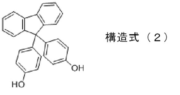
- Examples of the 9,9-bis (hydroxyphenyl) fluorene include 9,9-bis (4-hydroxyphenyl) fluorene (a compound represented by the following structural formula (2)).
- Examples of the 9,9-bis (alkyl-hydroxyphenyl) fluorene include 9,9-bis (4-hydroxy-3-methylphenyl) fluorene and 9,9-bis (4-hydroxy-3,5-dimethyl). Phenyl) fluorene and the like.
- epihalohydrin examples include epichlorohydrin.
- the bifunctional epoxy compound is not particularly limited and may be appropriately selected depending on the intended purpose. Examples thereof include bisphenol A type epoxy resin, bisphenol F type epoxy resin, and bisphenol S type epoxy resin.
- Examples of the other polyhydric phenols include bisphenol A, bisphenol F, and bisphenol S.
- the method for producing the fluorene type phenoxy resin is not particularly limited and may be appropriately selected depending on the intended purpose.
- a known method for producing a phenoxy resin can be referred to.
- a method for producing the fluorene type phenoxy resin for example, a method for producing a phenoxy resin described in JP-A-2008-255308 can be referred to.
- the fluorene type phenoxy resin may be a commercially available product.
- FX293 made by Nippon Steel Chemical Co., Ltd.
- FX280S made by Nippon Steel Chemical Co., Ltd.
- the content of the fluorene type phenoxy resin is not particularly limited and may be appropriately selected depending on the intended purpose, but is preferably 10% by mass to 40% by mass, and more preferably 20% by mass to 30% by mass.
- the content is less than 10% by mass, the adhesiveness may decrease, and when it exceeds 40% by mass, the connection reliability may decrease.
- the content is within the more preferable range, it is advantageous in that both adhesiveness and connection reliability are more excellent.
- the fluorene type epoxy resin is not particularly limited as long as it is an epoxy resin having a fluorene skeleton, and can be appropriately selected according to the purpose.
- fluorene type epoxy resin examples include (iv) an epoxy resin obtained by a reaction between the polyhydric phenol having the fluorene skeleton and the epihalohydrin, (v) a polyhydric phenol having the fluorene skeleton, and the bifunctional compound. Epoxy resin obtained by reaction with a functional epoxy compound, (vi) epoxy resin obtained by reaction of diglycidyl ether of polyhydric phenol having the fluorene skeleton with the other polyhydric phenol, and the like.
- a phenoxy resin and an epoxy resin can be manufactured using the same raw material, and can be manufactured separately by controlling reaction conditions (for example, mixture ratio).
- the method for producing the fluorene type epoxy resin is not particularly limited and may be appropriately selected depending on the intended purpose.
- a known method for producing an epoxy resin can be referred to.
- the method for producing the fluorene type epoxy resin for example, the method for producing an epoxy resin described in JP2012-102228A can be referred to.
- the fluorene type epoxy resin may be a commercially available product.
- the commercially available products include Oxol CG50 (manufactured by Osaka Gas Chemical Co., Ltd.) and Oxol CG500 (manufactured by Osaka Gas Chemical Co., Ltd.).
- the content of the fluorene type epoxy resin is not particularly limited and may be appropriately selected depending on the intended purpose, but is preferably 10% by mass to 40% by mass, and more preferably 20% by mass to 30% by mass.
- the content is less than 10% by mass, the connection reliability may be lowered, and when it exceeds 40% by mass, the adhesiveness may be lowered.
- the content is within the more preferable range, it is advantageous in that both adhesiveness and connection reliability are more excellent.
- the mass ratio (A: B) between the fluorene type phenoxy resin (A) and the fluorene type epoxy resin (B) is not particularly limited and may be appropriately selected depending on the intended purpose. : 3.0 to 3.0: 1.0 is preferable, and 1.0: 1.5 to 1.5: 1.0 is more preferable.
- the mass ratio (A: B) if the ratio of the fluorene-type phenoxy resin (A) is smaller than the preferable range, the adhesiveness may be reduced.
- the mass ratio (A: B) the When the ratio of the fluorene type phenoxy resin (A) is larger than the preferable range, the connection reliability may be lowered. When the mass ratio (A: B) is within the more preferable range, it is advantageous in that both adhesion and connection reliability are more excellent.
- ⁇ Curing agent> There is no restriction
- the imidazole curing agent include 2-ethyl 4-methylimidazole.
- the anionic curing agent include organic amines.
- the cationic curing agent include a sulfonium salt, an onium salt, and an aluminum chelating agent. Of these, imidazole curing agents are preferred.
- the curing agent is a curing agent that reacts with an epoxy group of the fluorene type epoxy resin or a curing agent that initiates polymerization of the epoxy group.
- the content of the curing agent is not particularly limited and may be appropriately selected depending on the intended purpose, but is preferably 10% by mass to 50% by mass, more preferably 20% by mass to 40% by mass, and 25% by mass. From 35% by weight is particularly preferred.
- the said silver coat copper powder is copper powder which covered at least one part of the surface with silver.
- connection reliability is further improved.
- the silver-coated copper powder is such that at least a part of the surface of the copper powder is coated with silver.
- the silver-coated copper powder may be one in which the entire surface of the copper powder is coated with silver, or a part of the surface of the copper powder may be coated with silver.
- the silver is coated unevenly over the entire copper powder surface while exposing the copper powder surface in places rather than the silver being unevenly distributed on a part of the copper powder surface. It is preferable that By coating without uneven distribution, silver-coated copper powder with uniform conductivity can be obtained.
- the coated silver is in a state of adhering to the surface of the copper powder in the form of dots or meshes.
- the silver-coated copper powder may be coated with a fatty acid.
- a fatty acid By covering the silver-coated copper powder with the fatty acid, the surface of the silver-coated copper powder is smoothed.
- a stearic acid etc. are mentioned.
- the silver ion solution is added to the dispersion to promote the reduction reaction, and further, the reducing agent is added to completely reduce and precipitate the silver powder on the surface of the copper powder.
- a method of depositing a film for example, see JP-A-1-119602.
- a method in which silver is coated on the surface of copper particles by a substitution reaction between silver ions and metallic copper in an organic solvent-containing solution containing silver ions see, for example, JP-A-2006-161081).
- the copper powder processed into flakes is heat treated to oxidize the copper powder surface, and then the copper powder is removed from the copper powder surface in an alkaline solution and washed with water, and then the copper powder surface in an acidic solution. Then, the oxide is pickled and washed with water, and then a reducing agent is added to the acidic solution in which the copper powder is dispersed to adjust the pH to prepare a copper powder slurry.
- the silver ion solution is continuously added to the copper powder slurry.
- a method of forming a silver layer on the surface of copper powder by electroless displacement plating and reduction type electroless plating for example, see JP 2010-174411 A). Among these, the method [5] is preferable.
- the average particle diameter of the conductive particles is not particularly limited and may be appropriately selected depending on the intended purpose, but is preferably 1 ⁇ m to 50 ⁇ m, more preferably 3 ⁇ m to 30 ⁇ m, and particularly preferably 5 ⁇ m to 20 ⁇ m.
- the average particle diameter can be measured by, for example, a particle size distribution measuring device (Microtrac MT3100, manufactured by Nikkiso Co., Ltd.).
- the content of the conductive particles is not particularly limited and may be appropriately selected depending on the intended purpose, but is preferably 2% by mass to 25% by mass, more preferably 2% by mass to 15% by mass, and 2% by mass. % To 10% by mass is more preferable, and 3.5% to 6.5% by mass is particularly preferable.
- the content is less than 2% by mass, the connection reliability may be lowered, and when it exceeds 25% by mass, the adhesiveness and the connection reliability may be lowered.
- the content is within the particularly preferable range, it is advantageous in that adhesiveness and connection reliability are more excellent.
- the other components are not particularly limited and may be appropriately selected depending on the purpose.
- silane coupling agents for example, silane coupling agents, rubbers, fillers, softeners, accelerators, anti-aging agents, organic solvents, ion catchers Agents and the like.
- the content of the other components is not particularly limited and can be appropriately selected depending on the purpose.
- the temperature (Tg) of the main dispersion tan ⁇ peak after curing of the conductive adhesive for solar cells is not particularly limited and may be appropriately selected depending on the intended purpose, but is preferably 190 ° C. or higher, preferably 190 ° C. to 225 ° C is more preferable, and 193 ° C to 215 ° C is particularly preferable. Connection reliability may fall that the said temperature is less than 190 degreeC.
- the main dispersion tan ⁇ peak value after curing of the conductive adhesive for solar cells is not particularly limited and may be appropriately selected depending on the intended purpose, but is preferably 0.40 or more, preferably 0.40 to 0.00. 50 is more preferable, and 0.45 to 0.50 is particularly preferable.
- the storage elastic modulus at ⁇ 40 ° C. after curing of the conductive adhesive for solar cells is not particularly limited and may be appropriately selected depending on the intended purpose. 10 9 Pa to 4.1 ⁇ 10 9 Pa is preferable. The storage elastic modulus at ⁇ 40 ° C. after curing is considered as a physical quantity related to adhesion. The storage elastic modulus at 170 ° C. after curing of the conductive adhesive for solar cells is not particularly limited and may be appropriately selected depending on the intended purpose. From the viewpoint of connection reliability, 1.9 ⁇ 10 8 Pa to 2.2 ⁇ 10 8 Pa is preferable. The storage elastic modulus at 170 ° C. after curing is considered as a physical quantity related to connection reliability.
- the temperature (Tg) of the main dispersion tan ⁇ peak after curing of the conductive adhesive for solar cell, the main dispersion tan ⁇ peak value, the storage elastic modulus at ⁇ 40 ° C., and the storage elastic modulus at 170 ° C. are, for example, It can be measured by this method.
- a conductive adhesive film having an average thickness of 20 ⁇ m is formed on the peeled PET using the conductive adhesive for solar cells. Subsequently, the conductive adhesive film is placed in a heating furnace at 200 ° C. and heated for 30 minutes to cure the conductive adhesive film and obtain a cured product.
- the cured product is peeled off from the peeled PET, cut into a 3.5 mm ⁇ 0.4 mm strip, and used as a measurement sample.
- a dynamic viscoelasticity measuring device (frequency 11 Hz)
- the measurement sample is heated from ⁇ 60 ° C. to 200 ° C. at a heating rate of 3 ° C./min.
- the main dispersion tan ⁇ peak value, the temperature at which the main dispersion tan ⁇ peak appears, the storage elastic modulus at ⁇ 40 ° C., and the storage elastic modulus at 170 ° C. are obtained.
- the dynamic viscoelasticity measuring device include DDV-01FP (manufactured by ORIENTEC).
- the solar cell conductive adhesive may be in the form of a liquid or a film.
- the solar battery module of the present invention has at least a solar battery cell, a tab wire, and a cured product of a conductive adhesive, and, if necessary, a sealing resin, a moisture-proof backsheet, a glass plate, etc. It has other members.
- the tab wire and the electrode of the solar battery cell are connected using a cured product of the conductive adhesive.
- the said conductive adhesive is the said conductive adhesive for solar cells of this invention.
- the solar battery cell is not particularly limited as long as it has electrodes, and can be appropriately selected according to the purpose.
- the solar battery cell has at least a photoelectric conversion element as a photoelectric conversion unit, a finger electrode, and a bus bar electrode. Furthermore, it has other members as required.
- Examples of the solar battery cell include a thin film solar battery cell and a crystalline solar battery cell.
- Examples of the thin film solar cell include an amorphous silicon solar cell, a CdS / CdTe solar cell, a dye-sensitized solar cell, an organic thin film solar cell, a microcrystalline silicon solar cell (tandem solar cell). Cell).
- Examples of the crystalline solar battery cell include a single crystal silicon solar battery cell and a polycrystalline silicon solar battery cell.
- the solar battery cell may have a bus bar-less structure without a bus bar electrode. There is no restriction
- the finger electrode is an electrode that collects electricity generated in the photoelectric conversion unit.
- the finger electrode is formed on the solar battery cell in a direction substantially orthogonal to the tab line.
- the bus bar electrode is an electrode that further collects electricity collected by the finger electrodes and transmits the electricity to the tab wire.
- the bus bar electrode is an electrode that further collects electricity collected by the finger electrodes and transmits the electricity to the tab wire.
- electricity is directly transmitted from the finger electrode to the tab wire.
- the tab line is not particularly limited as long as it is a line that electrically connects adjacent solar cells, and can be appropriately selected according to the purpose. There is no restriction
- the sealing resin is not particularly limited and may be appropriately selected depending on the purpose.
- ethylene / vinyl acetate copolymer (EVA), ethylene / vinyl acetate / triallyl isocyanurate (EVAT) examples include polyvinyl butyrate (PVB), polyisobutylene (PIB), silicone resin, polyurethane resin, and the like.
- ⁇ Dampproof back sheet> There is no restriction
- PET polyethylene terephthalate
- Al aluminum
- PET aluminum
- Al polyethylene
- PE polyethylene
- Glass plate> There is no restriction
- the solar cell module may be a thin film solar cell module using the thin film solar cell or a crystalline solar cell module using the crystal solar cell.
- FIG. 1 is a schematic top view showing an example of a thin-film solar cell module 200.
- thin-film solar cells 32 made of thin-film photoelectric conversion elements are arranged in series on a substrate 38 in a planar direction.
- the surface electrode (not shown) of the thin film solar cell 32c at one end and the surface electrode (not shown) of the thin film solar cell 32d at the other end are provided with a conductive adhesive layer (not shown).
- a tab wire 3 for power extraction is connected.
- FIG. 2 is an exploded perspective view showing an example of a crystalline solar cell module.
- the crystalline solar cell module 1 includes strings 4 in which a plurality of crystalline solar cells 2 are connected in series by tab wires 3 serving as interconnectors, and further includes a matrix 5 in which a plurality of strings 4 are arranged.
- the solar cell module 1 is laminated together with a matrix 5 sandwiched between sealing resin sheets 6 and a front cover 7 provided on the light receiving surface side and a moisture-proof back sheet 8 provided on the back surface side. Is done.
- the crystalline solar cell module 1 is formed by attaching a metal frame 9 such as aluminum around the periphery.
- each crystalline solar cell 2X, 2Y, 2Z of the crystalline solar cell module has a crystalline photoelectric conversion element 10 made of a silicon substrate.
- the crystalline photoelectric conversion element 10 is provided with a bus bar electrode 11 serving as a surface electrode on the light receiving surface side and a finger electrode 12 serving as a collecting electrode formed in a direction substantially orthogonal to the bus bar electrode 11.
- the crystalline photoelectric conversion element 10 is provided with an Al back electrode 13 made of aluminum on the back side opposite to the light receiving surface. Then, the bus bar electrode 11 on the surface of the solar battery cell 2 and the Al back electrode 13 of the adjacent solar battery cell 2 are electrically connected by the tab wire 3, thereby constituting the strings 4 connected in series. .
- the connection between the tab wire 3 and the bus bar electrode 11 and the connection between the tab wire 3 and the Al back electrode 13 are performed by, for example, the conductive adhesive film 17.
- the manufacturing method of the solar cell module of the present invention includes at least a disposing step, a covering step, a pressing step, and a heating step, and further includes other steps as necessary.
- the manufacturing method of the solar cell module of this invention can be used suitably for manufacture of the said solar cell module of this invention.
- the conductive adhesive is connected to the electrode and the tab wire via a cured product formed by curing the conductive adhesive by heating on the electrode of the solar battery cell. And if it is the process of arrange
- Examples of the solar battery cell include the solar battery cell exemplified in the description of the solar battery module of the present invention.
- Examples of the tab lines include the tab lines exemplified in the description of the solar cell module of the present invention.
- the said conductive adhesive is the said conductive adhesive for solar cells of this invention.
- the conductive adhesive may be in a liquid form or a film form.
- a film-like conductive adhesive (conductive adhesive film) slit to the same width as the bus bar electrode is placed on the bus bar electrode of the solar battery cell. Subsequently, a copper foil (tab wire) having the same width as the bus bar electrode is placed on the conductive adhesive film.
- positioning process can be performed by the above.
- a tab line with an adhesive layer having the same width as the bus bar electrode of the solar battery cell is prepared.
- the tab line with the adhesive layer is, for example, a film-like conductive adhesive (conductive adhesive film) is placed on a copper foil, and the copper foil on which the conductive adhesive film is placed is connected to the bus bar electrode of the solar battery cell. It is obtained by slitting to the same width.
- the tab line with the adhesive layer is placed on the bus bar electrode of the solar battery cell so that the bus bar electrode and the adhesive layer of the tab line with the adhesive layer are in contact with each other.
- positioning process can be performed by the above.
- the covering step is not particularly limited as long as it is a step of covering the solar battery cell with a sealing resin and further covering the sealing resin with either a moisture-proof backsheet or a glass plate. Can be selected as appropriate.
- the above solar cell module manufacturing method is preferably performed using a decompression laminator.
- the method using the reduced pressure laminator can be carried out with reference to the method described in JP 2010-283059 A, for example.
- the sealing resin, the moisture-proof backsheet, and the glass plate are not particularly limited and can be appropriately selected according to the purpose.
- examples thereof include a sealing resin, the moisture-proof backsheet, and the glass plate.
- the pressing step is not particularly limited as long as it is a step of pressing either the moisture-proof backsheet or the glass plate, and can be appropriately selected according to the purpose.
- the pressure to press and the time to press are arbitrary.
- the heating step is not particularly limited as long as it is a step of heating the heating stage on which the solar battery cell is placed, and can be appropriately selected according to the purpose.
- the sealing resin can be heated by heating the heating stage. Further, the conductive adhesive can be heated.
- the heating temperature in the heating step is not particularly limited and may be appropriately selected depending on the intended purpose, but is preferably 50 ° C to 250 ° C, more preferably 100 ° C to 200 ° C.
- sealing may be insufficient.
- the heating temperature exceeds 250 ° C., the organic resin contained in the conductive adhesive, the sealing resin, or the like may be thermally decomposed. is there.
- the heating temperature is within the more preferable range, it is advantageous in terms of sealing reliability.
- the heating time in the heating step is not particularly limited and may be appropriately selected depending on the intended purpose, but is preferably 1 second to 1 hour, more preferably 5 seconds to 30 minutes, and particularly preferably 10 seconds to 20 minutes. preferable. If the heating time is less than 1 second, sealing may be insufficient. When the heating time is within the particularly preferable range, it is advantageous in terms of sealing reliability.
- the order of starting the pressing step and the heating step is not particularly limited and may be appropriately selected depending on the purpose.
- the solar cell By performing the pressing step and the heating step, the solar cell can be sealed, and the electrode of the solar cell and the tab wire can be connected via a cured product of the conductive adhesive. .
- the solar cell module of the present invention is manufactured. Further, for example, the solar cell module of the present invention can be manufactured by forming a matrix in which a plurality of strings in which a plurality of solar cells are directly connected are arranged and sealing the matrix.
- the average thickness is a value obtained by measuring the thickness of 10 arbitrary points to be measured and averaging them.
- the average width is a value obtained by measuring the widths of arbitrary 10 points to be measured and averaging them.
- the 500 g of this flaky copper powder was heat-treated in the atmosphere at 250 ° C. for 5 minutes (oxidation treatment). Thereafter, the oxidized copper powder was added to a mortar and coarsely crushed. 500 g of this copper powder was added to 1,000 mL of a 1% by mass potassium hydroxide aqueous solution and stirred for 20 minutes, followed by primary decantation treatment, and further 1,000 mL of pure water was added and stirred for several minutes.
- a sixth decantation treatment was performed, and 2,500 mL of a 1% by mass sodium potassium tartrate aqueous solution was added and stirred for several minutes to form a copper slurry.
- a dilute sulfuric acid or potassium hydroxide solution was added to the copper slurry to adjust the pH of the copper slurry to 3.5 to 4.5.
- 500 g of the silver-coated copper powder obtained as described above was placed in a tubular furnace and heat-treated at 200 ° C. for 30 minutes in a reducing atmosphere under a hydrogen stream (3.0 L / min to 3.5 L / min).
- the heat-treated silver-coated copper powder was pulverized in a mortar.
- 500 g of the crushed silver-coated copper powder was dispersed in 1,000 mL of a 0.5% by mass isopropyl stearate solution and stirred for 30 minutes.
- Example 1 ⁇ Production of solar cell module model> -Production of conductive adhesive film- 25 parts by mass of fluorene type phenoxy resin (FX293, manufactured by Nippon Steel Chemical Co., Ltd.), 25 parts by mass of fluorene type epoxy resin (Oxol CG50, manufactured by Osaka Gas Chemical Co., Ltd.), acrylic rubber (Taisan Resin SGP3, manufactured by Nagase ChemteX Corporation) 15 parts by mass, curing agent (imidazole-based curing agent, NovaCure HX3941HP, manufactured by Asahi Kasei E-Materials Co., Ltd.), and conductive particles (silver-coated copper powder obtained in Production Example 1, average particle size 10 ⁇ m) 5 masses Parts were mixed to prepare a conductive adhesive composition.
- fluorene type phenoxy resin FX293, manufactured by Nippon Steel Chemical Co., Ltd.
- Fluorene type epoxy resin Oxol CG50, manufactured by Osaka Gas Chemical
- the obtained conductive adhesive composition was applied onto a polyethylene terephthalate film (release film) having a thickness of 50 ⁇ m whose surface was subjected to a release treatment.
- a conductive adhesive film having an average thickness of 25 ⁇ m was obtained.
- a copper foil was produced by laminating the conductive adhesive film on a copper foil (average thickness 150 ⁇ m) and laminating the conductive adhesive film. Subsequently, the copper foil on which the conductive adhesive film was laminated was slit to an average width of 1.5 mm to produce a tab wire with an adhesive layer.
- a glass substrate on which a finger electrode 12 as shown in FIG. 4 and a pattern with a bus bar electrode 11 substantially orthogonal to the finger electrode 12 was formed was produced.
- a silver paste was screen-printed and fired on a glass substrate (length 64 mm ⁇ width 64 mm ⁇ thickness 2.8 mm) to form a pattern of finger electrodes 12 and bus bar electrodes 11 as shown in FIG.
- the average width of the finger electrodes was 100 ⁇ m.
- the average width of the bus bar electrode was 2 mm.
- the obtained solar cell model with tab wires was covered with a sealing resin, and the sealing resin was further covered with a moisture-proof backsheet.
- a sealing resin an ethylene / vinyl acetate copolymer having a thickness of 500 ⁇ m was used.
- a PET film was used for the back sheet.
- sealing with the sealing resin was performed using a reduced pressure laminator. Specifically, vacuuming was performed at 100 ° C. for 5 minutes, followed by laminating at a press time of 5 minutes and 0.1 MPa, and then curing in an oven at 155 ° C. for 45 minutes.
- a solar cell module model was obtained.
- Example preparation A conductive adhesive film having an average thickness of 20 ⁇ m was formed on the peeled PET. Subsequently, the conductive adhesive film was placed in a heating furnace at 200 ° C. and heated for 30 minutes to cure the conductive adhesive film, thereby obtaining a cured product. The cured product was peeled from the peeled PET and cut into a 3.5 mm ⁇ 0.4 mm strip to obtain a measurement sample. Main dispersion tan ⁇ peak when the measurement sample was heated from ⁇ 60 ° C.
- Table 1 shows the mass ratio of the fluorene type phenoxy resin and the fluorene type epoxy resin while maintaining the total amount (50 parts by mass) of the fluorene type phenoxy resin and the fluorene type epoxy resin in the production of the conductive adhesive film of Example 1.
- a conductive adhesive film, a solar cell model with a tab line, and a solar cell module model were produced and evaluated in the same manner as in Example 1 except that the mass ratio was changed to that described in. The results are shown in Table 1.
- Example 6 In the production of the conductive adhesive film of Example 1, while maintaining the blending amounts of 25 parts by mass of fluorene type phenoxy resin, 25 parts by mass of fluorene type epoxy resin, 15 parts by mass of acrylic rubber, and 30 parts by mass of curing agent, The conductive adhesive film and the tab wire were the same as in Example 1 except that the blending amount of the conductive particles was changed so that the content of the conductive particles in the conductive adhesive composition was the content shown in Table 1. An attached solar cell model and a solar cell module model were prepared and evaluated. The results are shown in Table 1.
- Table 2 shows the mass ratio of the fluorene type phenoxy resin and the fluorene type epoxy resin while maintaining the total amount (50 parts by mass) of the fluorene type phenoxy resin and the fluorene type epoxy resin in the production of the conductive adhesive film of Example 1.
- a conductive adhesive film, a solar cell model with a tab line, and a solar cell module model were produced and evaluated in the same manner as in Example 1 except that the mass ratio was changed to that described in. The results are shown in Table 2.
- Example 10 In the production of the conductive adhesive film of Example 1, while maintaining the blending amounts of 25 parts by mass of fluorene type phenoxy resin, 25 parts by mass of fluorene type epoxy resin, 15 parts by mass of acrylic rubber, and 30 parts by mass of curing agent, The conductive adhesive film and the tab wire were the same as in Example 1 except that the blending amount of the conductive particles was changed so that the content of the conductive particles in the conductive adhesive composition was the content shown in Table 2. An attached solar cell model and a solar cell module model were prepared and evaluated. The results are shown in Table 2.
- Example 12 In the production of the conductive adhesive film of Example 1, a conductive adhesive film and a tab were obtained in the same manner as in Example 1 except that the fluorene type phenoxy resin was changed to a fluorene type phenoxy resin (FX280S, manufactured by Nippon Steel Chemical Co., Ltd.). A solar cell model with a line and a solar cell module model were prepared and evaluated. The results are shown in Table 2.
- Example 13 In the production of the conductive adhesive film of Example 1, a conductive adhesive film was obtained in the same manner as in Example 1 except that the fluorene type epoxy resin was changed to a fluorene type epoxy resin (Ocsol CG500, manufactured by Osaka Gas Chemical Co., Ltd.). A solar cell model with a tab line and a solar cell module model were prepared and evaluated. The results are shown in Table 2.
- Example 14 In the production of the conductive adhesive film of Example 1, except that the conductive particles were changed to nickel particles (HCA-1, manufactured by Inco), the conductive adhesive film and the sun with tab wire were the same as in Example 1. A battery cell model and a solar cell module model were produced and evaluated. The results are shown in Table 2.
- Example 6 Comparative Examples 1 to 6
- the conductive adhesive film, the solar cell model with tab wire, and the solar cell A module model was created and evaluated. The results are shown in Table 3.
- the bisphenol type phenoxy resin used in Comparative Examples 1, 5 and 6 is PKHH (manufactured by InChem).
- the fluorene type phenoxy resin used in Comparative Examples 2 to 4 is FX293 (manufactured by Nippon Steel Chemical Co., Ltd.).
- the fluorene type epoxy resin used in Comparative Example 1 is Oxol CG50 (manufactured by Osaka Gas Chemical Co., Ltd.).
- the naphthalene type epoxy resin used in Comparative Examples 2 and 6 is HP4710 (manufactured by DIC Corporation).
- the phenol novolac type epoxy resin used in Comparative Example 3 is N540 (manufactured by DIC Corporation).
- the bisphenol A type epoxy resin used in Comparative Examples 4 and 5 is YL980 (manufactured by Mitsubishi Chemical Corporation).
- the mass ratio (A: B) of the fluorene type phenoxy resin (A) and the fluorene type epoxy resin (B) is extremely excellent in both adhesiveness and connection reliability. It was confirmed that 1.5: 1.0 was particularly preferable (for example, see Examples 1, 8 and 9). It was confirmed that the content of the conductive particles is particularly preferably 2 to 10 parts by mass because both the adhesiveness and the connection reliability are very excellent (see, for example, Examples 1, 10 and 11). ). As a kind of electroconductive particle, since both adhesiveness and connection reliability were very excellent, it has confirmed that a silver coat copper powder was especially preferable (for example, refer Example 1). On the other hand, in Comparative Examples 1 to 6 using a resin that is not a fluorene type as either phenoxy resin or epoxy resin, at least one of adhesiveness and connection reliability was insufficient (evaluation criterion “ ⁇ ”). .
- the solar cell module of the present invention is excellent in adhesiveness and connection reliability, it can be particularly suitably used for a solar cell module that requires durability.
Landscapes
- Chemical & Material Sciences (AREA)
- Organic Chemistry (AREA)
- Chemical Kinetics & Catalysis (AREA)
- Health & Medical Sciences (AREA)
- Polymers & Plastics (AREA)
- Medicinal Chemistry (AREA)
- Spectroscopy & Molecular Physics (AREA)
- Physics & Mathematics (AREA)
- Dispersion Chemistry (AREA)
- Engineering & Computer Science (AREA)
- Manufacturing & Machinery (AREA)
- Adhesives Or Adhesive Processes (AREA)
- Photovoltaic Devices (AREA)
- Pigments, Carbon Blacks, Or Wood Stains (AREA)
- Conductive Materials (AREA)
Description
本発明は、太陽電池用導電性接着剤、並びに太陽電池モジュール、及びその製造方法に関する。
太陽電池は、クリーンで無尽蔵に供給される太陽光を直接電気に変換するため、新しいエネルギー源として期待されている。
前記太陽電池は、例えば、タブ線を介して複数の太陽電池セルを接続した太陽電池モジュールとして用いられている。
従来のタブ線は、銅線表面にハンダを塗布したタイプが使用されていた。そして、太陽電池セルの電極とタブ線とは、ハンダを介して接続されていた。しかし、ハンダ接続には高温が必要であることから、受光面のパネル割れや反り、タブ線からはみ出した(漏洩した)ハンダによるショートなどが発生し、不具合の原因となっていた。
従来のタブ線は、銅線表面にハンダを塗布したタイプが使用されていた。そして、太陽電池セルの電極とタブ線とは、ハンダを介して接続されていた。しかし、ハンダ接続には高温が必要であることから、受光面のパネル割れや反り、タブ線からはみ出した(漏洩した)ハンダによるショートなどが発生し、不具合の原因となっていた。
そこで、ハンダに代わる接続材料として導電性接着剤が使用されてきている。例えば、太陽電池セルの表面電極とタブ線とが導電性接着剤を介して接続された太陽電池モジュールが提案されている(例えば、特許文献1参照)。
しかし、この提案の技術では、太陽電池セルとタブ線との高い接着性、及び高い接続信頼性を両立することが困難であるという問題がある。
しかし、この提案の技術では、太陽電池セルとタブ線との高い接着性、及び高い接続信頼性を両立することが困難であるという問題がある。
したがって、太陽電池セルとタブ線との高い接着性、及び高い接続信頼性を両立させることができる太陽電池用導電性接着剤、並びに該太陽電池用導電性接着剤を用いた太陽電池モジュール、及びその製造方法の提供が求められているのが現状である。
本発明は、従来における前記諸問題を解決し、以下の目的を達成することを課題とする。即ち、本発明は、太陽電池セルとタブ線との高い接着性、及び高い接続信頼性を両立させることができる太陽電池用導電性接着剤、並びに該太陽電池用導電性接着剤を用いた太陽電池モジュール、及びその製造方法を提供することを目的とする。
前記課題を解決するための手段としては、以下の通りである。即ち、
<1> 太陽電池セルの電極とタブ線とを接続させるために用いられ、
フルオレン型フェノキシ樹脂と、フルオレン型エポキシ樹脂と、硬化剤と、導電性粒子とを少なくとも含有することを特徴とする太陽電池用導電性接着剤である。
<2> フルオレン型フェノキシ樹脂(A)と、フルオレン型エポキシ樹脂(B)との質量比率(A:B)が、1.0:3.0~3.0:1.0である前記<1>に記載の太陽電池用導電性接着剤である。
<3> 導電性粒子の含有量が、2質量%~25質量%である前記<1>から<2>のいずれかに記載の太陽電池用導電性接着剤である。
<4> 硬化後の-40℃での貯蔵弾性率が、3.0×10⁹Pa~4.1×10⁹Paであり、硬化後の170℃での貯蔵弾性率が、1.9×10⁸Pa~2.2×10⁸Paである前記<1>から<3>のいずれかに記載の太陽電池用導電性接着剤である。
<5> 硬化後の主分散tanδピークの温度が、190℃以上であり、硬化後の主分散tanδピーク値が、0.40以上である前記<1>から<4>のいずれかに記載の太陽電池用導電性接着剤である。
<6> 導電性粒子が、銀コート銅粉である前記<1>から<5>のいずれかに記載の太陽電池用導電性接着剤である。
<7> 電極を有する太陽電池セルと、タブ線と、導電性接着剤の硬化物とを有し、
前記太陽電池セルの電極と前記タブ線とが、前記導電性接着剤の硬化物を用いて接続され、
前記導電性接着剤が、前記<1>から<6>のいずれかに記載の太陽電池用導電性接着剤であることを特徴とする太陽電池モジュールである。
<8> 電極を有する太陽電池セルの前記電極上に、加熱により導電性接着剤が硬化して形成される硬化物を介して前記電極とタブ線とが接続されるように、前記導電性接着剤及び前記タブ線を配置する配置工程と、
前記太陽電池セルを封止用樹脂により覆い、更に前記封止用樹脂を防湿性バックシート及びガラスプレートのいずれかにより覆う被覆工程と、
前記防湿性バックシート及びガラスプレートのいずれかを押圧する押圧工程と、
前記太陽電池セルが載置された加熱ステージを加熱する加熱工程と、を少なくとも含み、
前記導電性接着剤が、前記<1>から<6>のいずれかに記載の太陽電池用導電性接着剤であることを特徴とする太陽電池モジュールの製造方法である。
<1> 太陽電池セルの電極とタブ線とを接続させるために用いられ、
フルオレン型フェノキシ樹脂と、フルオレン型エポキシ樹脂と、硬化剤と、導電性粒子とを少なくとも含有することを特徴とする太陽電池用導電性接着剤である。
<2> フルオレン型フェノキシ樹脂(A)と、フルオレン型エポキシ樹脂(B)との質量比率(A:B)が、1.0:3.0~3.0:1.0である前記<1>に記載の太陽電池用導電性接着剤である。
<3> 導電性粒子の含有量が、2質量%~25質量%である前記<1>から<2>のいずれかに記載の太陽電池用導電性接着剤である。
<4> 硬化後の-40℃での貯蔵弾性率が、3.0×10⁹Pa~4.1×10⁹Paであり、硬化後の170℃での貯蔵弾性率が、1.9×10⁸Pa~2.2×10⁸Paである前記<1>から<3>のいずれかに記載の太陽電池用導電性接着剤である。
<5> 硬化後の主分散tanδピークの温度が、190℃以上であり、硬化後の主分散tanδピーク値が、0.40以上である前記<1>から<4>のいずれかに記載の太陽電池用導電性接着剤である。
<6> 導電性粒子が、銀コート銅粉である前記<1>から<5>のいずれかに記載の太陽電池用導電性接着剤である。
<7> 電極を有する太陽電池セルと、タブ線と、導電性接着剤の硬化物とを有し、
前記太陽電池セルの電極と前記タブ線とが、前記導電性接着剤の硬化物を用いて接続され、
前記導電性接着剤が、前記<1>から<6>のいずれかに記載の太陽電池用導電性接着剤であることを特徴とする太陽電池モジュールである。
<8> 電極を有する太陽電池セルの前記電極上に、加熱により導電性接着剤が硬化して形成される硬化物を介して前記電極とタブ線とが接続されるように、前記導電性接着剤及び前記タブ線を配置する配置工程と、
前記太陽電池セルを封止用樹脂により覆い、更に前記封止用樹脂を防湿性バックシート及びガラスプレートのいずれかにより覆う被覆工程と、
前記防湿性バックシート及びガラスプレートのいずれかを押圧する押圧工程と、
前記太陽電池セルが載置された加熱ステージを加熱する加熱工程と、を少なくとも含み、
前記導電性接着剤が、前記<1>から<6>のいずれかに記載の太陽電池用導電性接着剤であることを特徴とする太陽電池モジュールの製造方法である。
本発明によれば、従来における前記諸問題を解決し、前記目的を達成することができ、太陽電池セルとタブ線との高い接着性、及び高い接続信頼性を両立させることができる太陽電池用導電性接着剤、並びに該太陽電池用導電性接着剤を用いた太陽電池モジュール、及びその製造方法を提供することができる。
(太陽電池用導電性接着剤)
本発明の太陽電池用導電性接着剤は、少なくともフルオレン型フェノキシ樹脂と、フルオレン型エポキシ樹脂と、硬化剤と、導電性粒子とを含有し、更に必要に応じて、その他の成分を含有する。
前記太陽電池用導電性接着剤は、太陽電池セルの電極とタブ線とを接続させるために用いられる。
本発明の太陽電池用導電性接着剤は、少なくともフルオレン型フェノキシ樹脂と、フルオレン型エポキシ樹脂と、硬化剤と、導電性粒子とを含有し、更に必要に応じて、その他の成分を含有する。
前記太陽電池用導電性接着剤は、太陽電池セルの電極とタブ線とを接続させるために用いられる。
<フルオレン型フェノキシ樹脂>
前記フルオレン型フェノキシ樹脂としては、フルオレン骨格を有するフェノキシ樹脂であれば、特に制限はなく、目的に応じて適宜選択することができる。
前記フルオレン型フェノキシ樹脂としては、フルオレン骨格を有するフェノキシ樹脂であれば、特に制限はなく、目的に応じて適宜選択することができる。
フルオレンは、3環構造をもつ芳香族炭化水素であって、下記構造式(1)で表される。

前記フルオレン骨格とは、前記フルオレンを含む2価の有機基を意味する。前記フルオレン骨格としては、例えば、前記フルオレンの9位の位置の2つ水素原子が脱離した2価のフルオレン基などが挙げられる。
前記フルオレン型フェノキシ樹脂としては、例えば、(i)フルオレン骨格を有する多価フェノールと、エピハロヒドリンとの反応により得られるフェノキシ樹脂、(ii)フルオレン骨格を有する多価フェノールと、二官能性エポキシ化合物との反応により得られるフェノキシ樹脂、(iii)フルオレン骨格を有する多価フェノールのジグリシジルエーテルと、その他の多価フェノールとの反応により得られるフェノキシ樹脂などが挙げられる。
前記フルオレン骨格を有する多価フェノールとしては、例えば、下記一般式(1)で表される化合物などが挙げられる。

ただし、前記一般式(1)中、同一又は異なって環Z1及び環Z2は、芳香族炭化水素環を表し、R1a、R1b、R2a及びR2bは、同一又は異なって置換基を表す。k1及びk2は、同一又は異なって0~4の整数を表し、m1及びm2は、それぞれ0又は1以上の整数を表し、n1及びn2は、それぞれ0又は1以上の整数を表す。m1、m2、k1又はk2が、それぞれ2以上である場合、複数のR1a、R1b、R2a及びR2bは、それぞれ、同一又は異なっていてもよい。n1+n2は、2以上である。
前記n1は、1が好ましく、前記n2は、1が好ましい。
前記n1は、1が好ましく、前記n2は、1が好ましい。
前記芳香族炭化水素環としては、例えば、ベンゼン環、ナフタレン環などが挙げられる。
前記置換基としては、例えば、炭素数1~6のアルキル基などが挙げられる。前記炭素数1~6のアルキル基としては、例えば、メチル基、エチル基などが挙げられる。
前記置換基としては、例えば、炭素数1~6のアルキル基などが挙げられる。前記炭素数1~6のアルキル基としては、例えば、メチル基、エチル基などが挙げられる。
前記一般式(1)で表される化合物としては、例えば、9,9-ビス(ヒドロキシフェニル)フルオレン、9,9-ビス(アルキル-ヒドロキシフェニル)フルオレンなどが挙げられる。前記9,9-ビス(ヒドロキシフェニル)フルオレンとしては、例えば、9,9-ビス(4-ヒドロキシフェニル)フルオレン(下記構造式(2)で表される化合物)などが挙げられる。前記9,9-ビス(アルキル-ヒドロキシフェニル)フルオレンとしては、例えば、9,9-ビス(4-ヒドロキシ-3-メチルフェニル)フルオレン、9,9-ビス(4-ヒドロキシ-3,5-ジメチルフェニル)フルオレンなどが挙げられる。
前記エピハロヒドリンとしては、例えば、エピクロロヒドリンなどが挙げられる。
前記二官能性エポキシ化合物としては、特に制限はなく、目的に応じて適宜選択することができ、例えば、ビスフェノールA型エポキシ樹脂、ビスフェノールF型エポキシ樹脂、ビスフェノールS型エポキシ樹脂などが挙げられる。
前記その他の多価フェノールとしては、例えば、ビスフェノールA、ビスフェノールF、ビスフェノールSなどが挙げられる。
前記フルオレン型フェノキシ樹脂を製造する方法としては、特に制限はなく、目的に応じて適宜選択することができ、例えば、公知のフェノキシ樹脂の製造方法を参考にすることができる。前記フルオレン型フェノキシ樹脂を製造する方法は、例えば、特開2008-255308号公報に記載のフェノキシ樹脂の製造方法を参考にすることができる。
前記フルオレン型フェノキシ樹脂は、市販品であってもよい。前記市販品としては、例えば、FX293(新日鉄化学株式会社製)、FX280S(新日鉄化学株式会社製)などが挙げられる。
前記フルオレン型フェノキシ樹脂の含有量としては、特に制限はなく、目的に応じて適宜選択することができるが、10質量%~40質量%が好ましく、20質量%~30質量%がより好ましい。前記含有量が、10質量%未満であると、接着性が低下することがあり、40質量%を超えると、接続信頼性が低下することがある。前記含有量が、前記より好ましい範囲内であると、接着性及び接続信頼性の両方がより優れる点で有利である。
<フルオレン型エポキシ樹脂>
前記フルオレン型エポキシ樹脂としては、フルオレン骨格を有するエポキシ樹脂であれば、特に制限はなく、目的に応じて適宜選択することができる。
前記フルオレン型エポキシ樹脂としては、フルオレン骨格を有するエポキシ樹脂であれば、特に制限はなく、目的に応じて適宜選択することができる。
前記フルオレン型エポキシ樹脂としては、例えば、(iv)前記フルオレン骨格を有する多価フェノールと、前記エピハロヒドリンとの反応により得られるエポキシ樹脂、(v)前記フルオレン骨格を有する多価フェノールと、前記二官能性エポキシ化合物との反応により得られるエポキシ樹脂、(vi)前記フルオレン骨格を有する多価フェノールのジグリシジルエーテルと、前記その他の多価フェノールとの反応により得られるエポキシ樹脂などが挙げられる。
なお、フェノキシ樹脂とエポキシ樹脂は、同じ原料を用いて製造することができ、反応条件(例えば、配合比率)を制御することにより造り分けることができる。
なお、フェノキシ樹脂とエポキシ樹脂は、同じ原料を用いて製造することができ、反応条件(例えば、配合比率)を制御することにより造り分けることができる。
前記フルオレン型エポキシ樹脂を製造する方法としては、特に制限はなく、目的に応じて適宜選択することができ、例えば、公知のエポキシ樹脂の製造方法を参考にすることができる。前記フルオレン型エポキシ樹脂を製造する方法は、例えば、特開2012-102228号公報に記載のエポキシ樹脂の製造方法を参考にすることができる。
前記フルオレン型エポキシ樹脂は、市販品であってもよい。前記市販品としては、例えば、オクゾールCG50(大阪ガスケミカル株式会社製)、オクゾールCG500(大阪ガスケミカル株式会社製)などが挙げられる。
前記フルオレン型エポキシ樹脂の含有量としては、特に制限はなく、目的に応じて適宜選択することができるが、10質量%~40質量%が好ましく、20質量%~30質量%がより好ましい。前記含有量が、10質量%未満であると、接続信頼性が低下することがあり、40質量%を超えると、接着性が低下することがある。前記含有量が、前記より好ましい範囲内であると、接着性及び接続信頼性の両方がより優れる点で有利である。
前記フルオレン型フェノキシ樹脂(A)と、前記フルオレン型エポキシ樹脂(B)との質量比率(A:B)としては、特に制限はなく、目的に応じて適宜選択することができるが、1.0:3.0~3.0:1.0が好ましく、1.0:1.5~1.5:1.0がより好ましい。前記質量比率(A:B)において、前記フルオレン型フェノキシ樹脂(A)の割合が、前記好ましい範囲よりも小さいと、接着性が低下することがあり、前記質量比率(A:B)において、前記フルオレン型フェノキシ樹脂(A)の割合が、前記好ましい範囲よりも大きいと、接続信頼性が低下することがある。前記質量比率(A:B)が、前記より好ましい範囲内であると、接着性及び接続信頼性の両方がより優れる点で有利である。
<硬化剤>
前記硬化剤としては、特に制限はなく、目的に応じて適宜選択することができ、例えば、イミダゾール系硬化剤、アニオン系硬化剤、カチオン系硬化剤などが挙げられる。前記イミダゾール系硬化剤としては、例えば、2-エチル4-メチルイミダゾールなどが挙げられる。前記アニオン系硬化剤としては、例えば、有機アミン類などが挙げられる。前記カチオン系硬化剤としては、例えば、スルホニウム塩、オニウム塩、アルミニウムキレート剤などが挙げられる。
これらの中でも、イミダゾール系硬化剤が好ましい。
前記硬化剤としては、特に制限はなく、目的に応じて適宜選択することができ、例えば、イミダゾール系硬化剤、アニオン系硬化剤、カチオン系硬化剤などが挙げられる。前記イミダゾール系硬化剤としては、例えば、2-エチル4-メチルイミダゾールなどが挙げられる。前記アニオン系硬化剤としては、例えば、有機アミン類などが挙げられる。前記カチオン系硬化剤としては、例えば、スルホニウム塩、オニウム塩、アルミニウムキレート剤などが挙げられる。
これらの中でも、イミダゾール系硬化剤が好ましい。
前記硬化剤は、前記フルオレン型エポキシ樹脂のエポキシ基と反応する硬化剤又は前記エポキシ基の重合を開始させる硬化剤である。
前記硬化剤の含有量としては、特に制限はなく、目的に応じて適宜選択することができるが、10質量%~50質量%が好ましく、20質量%~40質量%がより好ましく、25質量%~35質量%が特に好ましい。
<導電性粒子>
前記導電性粒子としては、特に制限はなく、目的に応じて適宜選択することができ、例えば、金粉、銀粉、銅粉、ニッケル粉、金コート銅粉、銀コート銅粉などが挙げられる。
これらの中でも、銀コート銅粉が好ましい。
前記導電性粒子としては、特に制限はなく、目的に応じて適宜選択することができ、例えば、金粉、銀粉、銅粉、ニッケル粉、金コート銅粉、銀コート銅粉などが挙げられる。
これらの中でも、銀コート銅粉が好ましい。
-銀コート銅粉-
前記銀コート銅粉とは、表面の少なくとも一部を銀で覆った銅粉である。前記銀コート銅粉を用いることにより、接続信頼性がより優れる。また、発電効率が低下しない太陽電池用導電性接着剤を得ることもできる。
前記銀コート銅粉とは、表面の少なくとも一部を銀で覆った銅粉である。前記銀コート銅粉を用いることにより、接続信頼性がより優れる。また、発電効率が低下しない太陽電池用導電性接着剤を得ることもできる。
前記銀コート銅粉は、言い換えれば、銅粉の表面の少なくとも一部に銀がコートされているものである。前記銀コート銅粉は、銅粉の表面の全体が銀によりコートされているものであってもよいし、銅粉の表面の一部が銀によりコートされているものであってもよい。一部をコートする場合、銀が銅粉の表面の一部に偏在しているものよりも、銅粉表面を所々露出させながら銀が銅粉表面の全体に亘って偏在せずにコートしているものであるのが好ましい。偏在せずにコートすることにより、導通性が均一な銀コート銅粉を得ることができる。この場合、コートしている銀は銅粉の表面に点状、網目状などの形状で付着している状態となっている。
銅粉の粒径としては、特に制限はなく、目的に応じて適宜選択することができる。
前記銀コート銅粉は、脂肪酸により被覆されていてもよい。前記銀コート銅粉が前記脂肪酸により被覆されていることにより、銀コート銅粉の表面が平滑化される。前記脂肪酸としては、特に制限はなく、目的に応じて適宜選択することができ、例えば、ステアリン酸などが挙げられる。
前記銀コート銅粉の製造方法としては、特に制限はなく、目的に応じて適宜選択することができ、例えば、以下の[1]~[5]の方法などが挙げられる。
[1]硝酸銀、炭酸アンモニウム塩、及びEDTA(エチレンジアミン四酢酸)三ナトリウムの銀錯塩溶液を用いて金属銅粉の表面に金属銀を析出させる方法(例えば、特公昭57-59283号公報参照)。
[2]硝酸銀、アンモニア水、及びEDTAの銀錯塩溶液を用いて金属銅粉の表面に金属銀を析出させる方法(例えば、特開昭61-3802号公報参照)。
[3]キレート化剤溶液に銅粉を分散させた後、分散液に銀イオン溶液を加えて還元反応を促し、更に還元剤を添加して完全に還元析出させて、銅粉の表面に銀被膜を析出させる方法(例えば、特開平1-119602号公報参照)。
[4]銀イオンが存在する有機溶媒含有溶液中で、銀イオンと金属銅との置換反応により、銀を銅粒子の表面に被覆する方法(例えば、特開2006-161081号公報参照)。
[5]フレーク状に加工した銅粉を熱処理して銅粉表面を酸化し、次に、銅粉をアルカリ性溶液中で銅粉表面の有機物を除去及び水洗した後、酸性溶液中で銅粉表面の酸化物を酸洗及び水洗し、その後、この銅粉を分散させた酸性溶液中に還元剤を添加しpHを調整して銅粉スラリーを作製し、この銅粉スラリーに銀イオン溶液を連続的に添加することにより、無電解置換メッキと還元型無電解メッキにより銅粉表面に銀層を形成する方法(例えば、特開2010-174311号公報参照)。
これらの中でも、[5]の方法が好ましい。
[1]硝酸銀、炭酸アンモニウム塩、及びEDTA(エチレンジアミン四酢酸)三ナトリウムの銀錯塩溶液を用いて金属銅粉の表面に金属銀を析出させる方法(例えば、特公昭57-59283号公報参照)。
[2]硝酸銀、アンモニア水、及びEDTAの銀錯塩溶液を用いて金属銅粉の表面に金属銀を析出させる方法(例えば、特開昭61-3802号公報参照)。
[3]キレート化剤溶液に銅粉を分散させた後、分散液に銀イオン溶液を加えて還元反応を促し、更に還元剤を添加して完全に還元析出させて、銅粉の表面に銀被膜を析出させる方法(例えば、特開平1-119602号公報参照)。
[4]銀イオンが存在する有機溶媒含有溶液中で、銀イオンと金属銅との置換反応により、銀を銅粒子の表面に被覆する方法(例えば、特開2006-161081号公報参照)。
[5]フレーク状に加工した銅粉を熱処理して銅粉表面を酸化し、次に、銅粉をアルカリ性溶液中で銅粉表面の有機物を除去及び水洗した後、酸性溶液中で銅粉表面の酸化物を酸洗及び水洗し、その後、この銅粉を分散させた酸性溶液中に還元剤を添加しpHを調整して銅粉スラリーを作製し、この銅粉スラリーに銀イオン溶液を連続的に添加することにより、無電解置換メッキと還元型無電解メッキにより銅粉表面に銀層を形成する方法(例えば、特開2010-174311号公報参照)。
これらの中でも、[5]の方法が好ましい。
前記導電性粒子の平均粒径としては、特に制限はなく、目的に応じて適宜選択することができるが、1μm~50μmが好ましく、3μm~30μmがより好ましく、5μm~20μmが特に好ましい。前記平均粒径が、1μm未満であると、接続信頼性が不足することがあり、50μmを超えると、太陽電池セルが破損することがある。前記平均粒径が、前記特に好ましい範囲内であると、長期信頼性の点で有利である。
前記平均粒径は、例えば、粒度分布測定装置(マイクロトラックMT3100、日機装株式会社製)などにより測定することができる。
前記平均粒径は、例えば、粒度分布測定装置(マイクロトラックMT3100、日機装株式会社製)などにより測定することができる。
前記導電性粒子の含有量としては、特に制限はなく、目的に応じて適宜選択することができるが、2質量%~25質量%が好ましく、2質量%~15質量%がより好ましく、2質量%~10質量%が更に好ましく、3.5質量%~6.5質量%が特に好ましい。前記含有量が、2質量%未満であると、接続信頼性が低下することあり、25質量%を超えると、接着性及び接続信頼性が低下することがある。前記含有量が、前記特に好ましい範囲内であると、接着性及び接続信頼性がより優れる点で有利である。
<その他の成分>
前記その他の成分としては、特に制限はなく、目的に応じて適宜選択することができ、例えば、シランカップリング剤、ゴム、充填剤、軟化剤、促進剤、老化防止剤、有機溶剤、イオンキャッチャー剤などが挙げられる。前記その他の成分の含有量は、特に制限はなく、目的に応じて適宜選択することができる。
前記その他の成分としては、特に制限はなく、目的に応じて適宜選択することができ、例えば、シランカップリング剤、ゴム、充填剤、軟化剤、促進剤、老化防止剤、有機溶剤、イオンキャッチャー剤などが挙げられる。前記その他の成分の含有量は、特に制限はなく、目的に応じて適宜選択することができる。
-ゴム-
前記ゴムとしては、特に制限はなく、目的に応じて適宜選択することができ、例えば、アクリルゴムなどが挙げられる。
前記ゴムの含有量としては、特に制限はなく、目的に応じて適宜選択することができるが、5質量%~25質量%が好ましく、10質量%~20質量%がより好ましい。
前記ゴムとしては、特に制限はなく、目的に応じて適宜選択することができ、例えば、アクリルゴムなどが挙げられる。
前記ゴムの含有量としては、特に制限はなく、目的に応じて適宜選択することができるが、5質量%~25質量%が好ましく、10質量%~20質量%がより好ましい。
前記太陽電池用導電性接着剤の硬化後の主分散tanδピークの温度(Tg)としては、特に制限はなく、目的に応じて適宜選択することができるが、190℃以上が好ましく、190℃~225℃がより好ましく、193℃~215℃が特に好ましい。前記温度が、190℃未満であると、接続信頼性が低下することがある。
前記太陽電池用導電性接着剤の硬化後の主分散tanδピーク値としては、特に制限はなく、目的に応じて適宜選択することができるが、0.40以上が好ましく、0.40~0.50がより好ましく、0.45~0.50が特に好ましい。前記ピーク値が、0.40未満であると、接着性が低下することがある。
前記太陽電池用導電性接着剤の硬化後の-40℃での貯蔵弾性率としては、特に制限はなく、目的に応じて適宜選択することができるが、接着性の点から、3.0×10⁹Pa~4.1×10⁹Paが好ましい。硬化後の-40℃での貯蔵弾性率は、接着性に関連する物理量と考えられる。
前記太陽電池用導電性接着剤の硬化後の170℃での貯蔵弾性率としては、特に制限はなく、目的に応じて適宜選択することができるが、接続信頼性の点から、1.9×10⁸Pa~2.2×10⁸Paが好ましい。硬化後の170℃での貯蔵弾性率は、接続信頼性に関連する物理量と考えられる。
前記太陽電池用導電性接着剤の硬化後の主分散tanδピーク値としては、特に制限はなく、目的に応じて適宜選択することができるが、0.40以上が好ましく、0.40~0.50がより好ましく、0.45~0.50が特に好ましい。前記ピーク値が、0.40未満であると、接着性が低下することがある。
前記太陽電池用導電性接着剤の硬化後の-40℃での貯蔵弾性率としては、特に制限はなく、目的に応じて適宜選択することができるが、接着性の点から、3.0×10⁹Pa~4.1×10⁹Paが好ましい。硬化後の-40℃での貯蔵弾性率は、接着性に関連する物理量と考えられる。
前記太陽電池用導電性接着剤の硬化後の170℃での貯蔵弾性率としては、特に制限はなく、目的に応じて適宜選択することができるが、接続信頼性の点から、1.9×10⁸Pa~2.2×10⁸Paが好ましい。硬化後の170℃での貯蔵弾性率は、接続信頼性に関連する物理量と考えられる。
前記太陽電池用導電性接着剤の硬化後の主分散tanδピークの温度(Tg)、主分散tanδピーク値、-40℃での貯蔵弾性率、及び170℃での貯蔵弾性率は、例えば、以下の方法により測定できる。
前記太陽電池用導電性接着剤を用い、剥離処理したPET上に平均厚みが20μmの導電性接着フィルムを形成する。続いて、その導電性接着フィルムを200℃の加熱炉に入れ、30分間加熱することで前記導電性接着フィルムを硬化させ、硬化物を得る。その硬化物を前記剥離処理したPETから剥離し、3.5mm×0.4mmの短冊状に切り出し、測定試料とする。
動的粘弾性測定器(周波数11Hz)を用い、測定試料を-60℃から200℃まで昇温速度3℃/分間で昇温させる。そしてその際の、主分散tanδピーク値、主分散tanδピークが現れる温度、-40℃での貯蔵弾性率、及び170℃での貯蔵弾性率を求める。
前記動的粘弾性測定器としては、例えば、DDV-01FP(ORIENTEC社製)などが挙げられる。
前記太陽電池用導電性接着剤を用い、剥離処理したPET上に平均厚みが20μmの導電性接着フィルムを形成する。続いて、その導電性接着フィルムを200℃の加熱炉に入れ、30分間加熱することで前記導電性接着フィルムを硬化させ、硬化物を得る。その硬化物を前記剥離処理したPETから剥離し、3.5mm×0.4mmの短冊状に切り出し、測定試料とする。
動的粘弾性測定器(周波数11Hz)を用い、測定試料を-60℃から200℃まで昇温速度3℃/分間で昇温させる。そしてその際の、主分散tanδピーク値、主分散tanδピークが現れる温度、-40℃での貯蔵弾性率、及び170℃での貯蔵弾性率を求める。
前記動的粘弾性測定器としては、例えば、DDV-01FP(ORIENTEC社製)などが挙げられる。
前記太陽電池用導電性接着剤は、液状であってもよいし、フィルム状であってもよい。
(太陽電池モジュール)
本発明の太陽電池モジュールは、少なくとも太陽電池セルと、タブ線と、導電性接着剤の硬化物とを有し、更に必要に応じて、封止用樹脂、防湿性バックシート、ガラスプレートなどのその他の部材を有する。
前記タブ線と前記太陽電池セルの電極とは、前記導電性接着剤の硬化物を用いて接続されている。
前記導電性接着剤は、本発明の前記太陽電池用導電性接着剤である。
本発明の太陽電池モジュールは、少なくとも太陽電池セルと、タブ線と、導電性接着剤の硬化物とを有し、更に必要に応じて、封止用樹脂、防湿性バックシート、ガラスプレートなどのその他の部材を有する。
前記タブ線と前記太陽電池セルの電極とは、前記導電性接着剤の硬化物を用いて接続されている。
前記導電性接着剤は、本発明の前記太陽電池用導電性接着剤である。
<太陽電池セル>
前記太陽電池セルとしては、電極を有する限り、特に制限はなく、目的に応じて適宜選択することができ、例えば、光電変換部としての光電変換素子と、フィンガー電極と、バスバー電極とを少なくとも有し、更に必要に応じて、その他の部材を有する。
前記太陽電池セルとしては、電極を有する限り、特に制限はなく、目的に応じて適宜選択することができ、例えば、光電変換部としての光電変換素子と、フィンガー電極と、バスバー電極とを少なくとも有し、更に必要に応じて、その他の部材を有する。
前記太陽電池セルとしては、例えば、薄膜系太陽電池セル、結晶系太陽電池セルなどが挙げられる。前記薄膜系太陽電池セルとしては、例えば、非晶質シリコン太陽電池セル、CdS/CdTe太陽電池セル、色素増感太陽電池セル、有機薄膜太陽電池セル、微結晶シリコン太陽電池セル(タンデム型太陽電池セル)などが挙げられる。前記結晶系太陽電池セルとしては、例えば、単結晶シリコン太陽電池セル、多結晶シリコン太陽電池セルなどが挙げられる。
前記太陽電池セルは、バスバー電極を有さないバスバーレス構造であってもよい。
前記太陽電池セルの平均厚みとしては、特に制限はなく、目的に応じて適宜選択することができる。
前記太陽電池セルは、バスバー電極を有さないバスバーレス構造であってもよい。
前記太陽電池セルの平均厚みとしては、特に制限はなく、目的に応じて適宜選択することができる。
-フィンガー電極-
前記フィンガー電極は、前記光電変換部において生成した電気を収集する電極である。前記フィンガー電極は、前記太陽電池セル上において、前記タブ線とほぼ直交する方向に形成されている。
前記フィンガー電極の材質、形状、大きさ、構造としては、特に制限はなく、目的に応じて適宜選択することができる。
前記フィンガー電極は、前記光電変換部において生成した電気を収集する電極である。前記フィンガー電極は、前記太陽電池セル上において、前記タブ線とほぼ直交する方向に形成されている。
前記フィンガー電極の材質、形状、大きさ、構造としては、特に制限はなく、目的に応じて適宜選択することができる。
-バスバー電極-
前記バスバー電極は、前記フィンガー電極で収集した電気を更に収集し前記タブ線へ伝える電極である。
前記バスバー電極の材質、形状、大きさ、構造としては、特に制限はなく、目的に応じて適宜選択することができる。
なお、バスバーレス構造の太陽電池セルでは、前記フィンガー電極から直接前記タブ線へ電気が伝えられる。
前記バスバー電極は、前記フィンガー電極で収集した電気を更に収集し前記タブ線へ伝える電極である。
前記バスバー電極の材質、形状、大きさ、構造としては、特に制限はなく、目的に応じて適宜選択することができる。
なお、バスバーレス構造の太陽電池セルでは、前記フィンガー電極から直接前記タブ線へ電気が伝えられる。
<タブ線>
前記タブ線としては、隣接する前記太陽電池セルの各間を電気的に接続する線であれば、特に制限はなく、目的に応じて適宜選択することができる。
前記タブ線の材質、形状、大きさ、構造としては、特に制限はなく、目的に応じて適宜選択することができる。
前記タブ線としては、隣接する前記太陽電池セルの各間を電気的に接続する線であれば、特に制限はなく、目的に応じて適宜選択することができる。
前記タブ線の材質、形状、大きさ、構造としては、特に制限はなく、目的に応じて適宜選択することができる。
<封止用樹脂>
前記封止用樹脂としては、特に制限はなく、目的に応じて適宜選択することができ、例えば、エチレン/酢酸ビニル共重合体(EVA)、エチレン/酢酸ビニル/トリアリルイソシアヌレート(EVAT)、ポリビニルブチラート(PVB)、ポリイソブチレン(PIB)、シリコーン樹脂、ポリウレタン樹脂などが挙げられる。
前記封止用樹脂としては、特に制限はなく、目的に応じて適宜選択することができ、例えば、エチレン/酢酸ビニル共重合体(EVA)、エチレン/酢酸ビニル/トリアリルイソシアヌレート(EVAT)、ポリビニルブチラート(PVB)、ポリイソブチレン(PIB)、シリコーン樹脂、ポリウレタン樹脂などが挙げられる。
<防湿性バックシート>
前記防湿性バックシートとしては、特に制限はなく、目的に応じて適宜選択することができ、例えば、ポリエチレンテレフタレート(PET)、アルミニウム(Al)、PETとAlとポリエチレン(PE)の積層体などが挙げられる。
前記防湿性バックシートとしては、特に制限はなく、目的に応じて適宜選択することができ、例えば、ポリエチレンテレフタレート(PET)、アルミニウム(Al)、PETとAlとポリエチレン(PE)の積層体などが挙げられる。
<ガラスプレート>
前記ガラスプレートとしては、特に制限はなく、目的に応じて適宜選択することができ、例えば、ソーダ石灰フロートガラスプレートなどが挙げられる。
前記ガラスプレートとしては、特に制限はなく、目的に応じて適宜選択することができ、例えば、ソーダ石灰フロートガラスプレートなどが挙げられる。
前記太陽電池モジュールは、前記薄膜系太陽電池セルを用いた薄膜系太陽電池モジュールであってもよいし、前記結晶系太陽電池セルを用いた結晶系太陽電池モジュールであってもよい。
本発明の太陽電池モジュールの一例を、図を用いて説明する。
図1は、薄膜系太陽電池モジュール200の一例を示す概略上面図である。図1の薄膜系太陽電池モジュール200は、基材38上に、薄膜系光電変換素子からなる薄膜系太陽電池セル32が、直列に平面方向に配列されている。そして、一方の末端の薄膜系太陽電池セル32cの表面電極(不図示)及び他方の末端の薄膜系太陽電池セル32dの表面電極(不図示)には、導電性接着層(不図示)を介して、電力取り出し用のタブ線3が接続されている。
図1は、薄膜系太陽電池モジュール200の一例を示す概略上面図である。図1の薄膜系太陽電池モジュール200は、基材38上に、薄膜系光電変換素子からなる薄膜系太陽電池セル32が、直列に平面方向に配列されている。そして、一方の末端の薄膜系太陽電池セル32cの表面電極(不図示)及び他方の末端の薄膜系太陽電池セル32dの表面電極(不図示)には、導電性接着層(不図示)を介して、電力取り出し用のタブ線3が接続されている。
図2は、結晶系太陽電池モジュールの一例を示す分解斜視図である。結晶系太陽電池モジュール1は、複数の結晶系太陽電池セル2がインターコネクタとなるタブ線3によって直列に接続されたストリングス4を有し、更にストリングス4を複数配列したマトリクス5を備える。そして、太陽電池モジュール1は、マトリクス5が封止用樹脂のシート6で挟まれ、受光面側に設けられた表面カバー7及び裏面側に設けられた防湿性のバックシート8とともに一括してラミネートされる。最後に、周囲にアルミニウムなどの金属フレーム9が取り付けられることにより、結晶系太陽電池モジュール1が形成される。
また、図3に示すように、結晶系太陽電池モジュールの各結晶系太陽電池セル2X、2Y、2Zは、シリコン基板からなる結晶系光電変換素子10を有する。結晶系光電変換素子10には、受光面側に表面電極となるバスバー電極11と、バスバー電極11とほぼ直交する方向に形成された集電極であるフィンガー電極12とが設けられている。また、結晶系光電変換素子10には、受光面と反対の裏面側に、アルミニウムからなるAl裏面電極13が設けられている。
そして、タブ線3によって、太陽電池セル2の表面のバスバー電極11と、隣接する太陽電池セル2のAl裏面電極13とが電気的に接続され、これにより直列に接続されたストリングス4を構成する。タブ線3とバスバー電極11との接続、及びタブ線3とAl裏面電極13との接続は、例えば、導電性接着フィルム17によって行う。
そして、タブ線3によって、太陽電池セル2の表面のバスバー電極11と、隣接する太陽電池セル2のAl裏面電極13とが電気的に接続され、これにより直列に接続されたストリングス4を構成する。タブ線3とバスバー電極11との接続、及びタブ線3とAl裏面電極13との接続は、例えば、導電性接着フィルム17によって行う。
(太陽電池モジュールの製造方法)
本発明の太陽電池モジュールの製造方法は、配置工程と、被覆工程と、押圧工程と、加熱工程とを少なくとも含み、更に必要に応じて、その他の工程を含む。
本発明の太陽電池モジュールの製造方法は、本発明の前記太陽電池モジュールの製造に好適に用いることができる。
本発明の太陽電池モジュールの製造方法は、配置工程と、被覆工程と、押圧工程と、加熱工程とを少なくとも含み、更に必要に応じて、その他の工程を含む。
本発明の太陽電池モジュールの製造方法は、本発明の前記太陽電池モジュールの製造に好適に用いることができる。
<配置工程>
前記配置工程としては、太陽電池セルの電極上に、加熱により導電性接着剤が硬化して形成される硬化物を介して前記電極とタブ線とが接続されるように、前記導電性接着剤及び前記タブ線を配置する工程であれば、特に制限はなく、目的に応じて適宜選択することができる。
前記配置工程としては、太陽電池セルの電極上に、加熱により導電性接着剤が硬化して形成される硬化物を介して前記電極とタブ線とが接続されるように、前記導電性接着剤及び前記タブ線を配置する工程であれば、特に制限はなく、目的に応じて適宜選択することができる。
前記太陽電池セルとしては、例えば、本発明の前記太陽電池モジュールの説明において例示した前記太陽電池セルなどが挙げられる。
前記タブ線としては、例えば、本発明の前記太陽電池モジュールの説明において例示した前記タブ線などが挙げられる。
前記導電性接着剤は、本発明の前記太陽電池用導電性接着剤である。前記導電性接着剤は、液状であってもよいし、フィルム状であってもよい。
前記タブ線としては、例えば、本発明の前記太陽電池モジュールの説明において例示した前記タブ線などが挙げられる。
前記導電性接着剤は、本発明の前記太陽電池用導電性接着剤である。前記導電性接着剤は、液状であってもよいし、フィルム状であってもよい。
前記配置工程の一例を説明する。
前記太陽電池セルのバスバー電極上に、前記バスバー電極と同じ幅にスリットしたフィルム状の導電性接着剤(導電性接着フィルム)を置く。続いて、前記導電性接着フィルム上に、前記バスバー電極と同じ幅の銅箔(タブ線)を置く。以上により配置工程を行うことができる。
前記太陽電池セルのバスバー電極上に、前記バスバー電極と同じ幅にスリットしたフィルム状の導電性接着剤(導電性接着フィルム)を置く。続いて、前記導電性接着フィルム上に、前記バスバー電極と同じ幅の銅箔(タブ線)を置く。以上により配置工程を行うことができる。
前記配置工程の他の一例を説明する。
まず、前記太陽電池セルのバスバー電極と同じ幅の接着層付きタブ線を用意する。前記接着層付きタブ線は、例えば、銅箔上にフィルム状の導電性接着剤(導電性接着フィルム)を載せ、導電性接着フィルムが載った前記銅箔を、前記太陽電池セルのバスバー電極と同じ幅になるようにスリットすることにより得られる。
前記太陽電池セルのバスバー電極上に、前記バスバー電極と前記接着層付きタブ線の接着層とが接するように、前記接着層付きタブ線を置く。以上により配置工程を行うことができる。
まず、前記太陽電池セルのバスバー電極と同じ幅の接着層付きタブ線を用意する。前記接着層付きタブ線は、例えば、銅箔上にフィルム状の導電性接着剤(導電性接着フィルム)を載せ、導電性接着フィルムが載った前記銅箔を、前記太陽電池セルのバスバー電極と同じ幅になるようにスリットすることにより得られる。
前記太陽電池セルのバスバー電極上に、前記バスバー電極と前記接着層付きタブ線の接着層とが接するように、前記接着層付きタブ線を置く。以上により配置工程を行うことができる。
<被覆工程>
前記被覆工程としては、前記太陽電池セルを封止用樹脂により覆い、更に前記封止用樹脂を防湿性バックシート及びガラスプレートのいずれかにより覆う工程であれば、特に制限はなく、目的に応じて適宜選択することができる。
前記被覆工程としては、前記太陽電池セルを封止用樹脂により覆い、更に前記封止用樹脂を防湿性バックシート及びガラスプレートのいずれかにより覆う工程であれば、特に制限はなく、目的に応じて適宜選択することができる。
以上のような前記太陽電池モジュールの製造方法は、減圧ラミネーターを用いて行うことが好ましい。前記減圧ラミネーターを用いる方法は、例えば、特開2010-283059号公報に記載の方法を参考にして行うことができる。
前記封止用樹脂、前記防湿性バックシート、及び前記ガラスプレートとしては、特に制限はなく、目的に応じて適宜選択することができ、例えば、本発明の前記太陽電池モジュールの説明において例示した前記封止用樹脂、前記防湿性バックシート、及び前記ガラスプレートがそれぞれ挙げられる。
<押圧工程及び加熱工程>
前記押圧工程としては、前記防湿性バックシート及びガラスプレートのいずれかを押圧する工程であれば、特に制限はなく、目的に応じて適宜選択することができる。押圧する圧力、及び押圧する時間は、任意である。
前記押圧工程としては、前記防湿性バックシート及びガラスプレートのいずれかを押圧する工程であれば、特に制限はなく、目的に応じて適宜選択することができる。押圧する圧力、及び押圧する時間は、任意である。
前記加熱工程としては、前記太陽電池セルが載置された加熱ステージを加熱する工程であれば、特に制限はなく、目的に応じて適宜選択することができる。前記加熱ステージを加熱することにより、前記封止用樹脂を加熱することができる。また、前記導電性接着剤を加熱することができる。
前記加熱工程における加熱温度としては、特に制限はなく、目的に応じて適宜選択することができるが、50℃~250℃が好ましく、100℃~200℃がより好ましい。前記加熱温度が、50℃未満であると、封止が不十分となることがあり、250℃を超えると、導電性接着剤、封止用樹脂などに含まれる有機樹脂が熱分解することがある。前記加熱温度が、前記より好ましい範囲内であると、封止の信頼性の点で有利である。
前記加熱工程における加熱時間としては、特に制限はなく、目的に応じて適宜選択することができるが、1秒間~1時間が好ましく、5秒間~30分間がより好ましく、10秒間~20分間が特に好ましい。前記加熱時間が、1秒間未満であると、封止が不十分となることがある。前記加熱時間が、前記特に好ましい範囲内であると、封止の信頼性の点で有利である。
前記押圧工程、及び前記加熱工程を開始する順序としては、特に制限はなく、目的に応じて適宜選択することができる。
前記押圧工程及び前記加熱工程を行うことにより、前記太陽電池セルを封止するとともに、前記太陽電池セルの電極と前記タブ線とを前記導電性接着剤の硬化物を介して接続することができる。
以上のようにすることにより、本発明の太陽電池モジュールが製造される。
また、例えば、太陽電池セルを直接に複数接続したストリングスを更に複数配列したマトリクスを形成し、それを封止することにより、本発明の太陽電池モジュールを作製することもできる。
また、例えば、太陽電池セルを直接に複数接続したストリングスを更に複数配列したマトリクスを形成し、それを封止することにより、本発明の太陽電池モジュールを作製することもできる。
以下、本発明の実施例を説明するが、本発明は、これらの実施例に何ら限定されるものではない。
なお、以下の実施例において、平均厚みは、測定対象の任意の10点について厚みを測定し、それを平均した値である。平均幅は、測定対象の任意の10点について幅を測定し、それを平均した値である。
なお、以下の実施例において、平均厚みは、測定対象の任意の10点について厚みを測定し、それを平均した値である。平均幅は、測定対象の任意の10点について幅を測定し、それを平均した値である。
(製造例1)
<銀コート銅粉の製造>
アトマイズ法と呼ばれる製法により得られたアトマイズ銅粉に機械的粉砕を行って得られた銅粉を使用した。なお、機械的粉砕時には、銅粉同士の凝集による粗大化を防止する目的で脂肪酸が添加されていると推測される。具体的には、日本アトマイズ加工社製のフレーク銅粉(AFS-Cu 7μm)を使用した。この銅粉は、レーザー回折散乱式粒度分布測定法による重量累積粒径D50が7.9μmであった。
<銀コート銅粉の製造>
アトマイズ法と呼ばれる製法により得られたアトマイズ銅粉に機械的粉砕を行って得られた銅粉を使用した。なお、機械的粉砕時には、銅粉同士の凝集による粗大化を防止する目的で脂肪酸が添加されていると推測される。具体的には、日本アトマイズ加工社製のフレーク銅粉(AFS-Cu 7μm)を使用した。この銅粉は、レーザー回折散乱式粒度分布測定法による重量累積粒径D50が7.9μmであった。
このフレーク状の銅粉500gを大気中で250℃、5分間熱処理した(酸化処理)。その後、酸化処理した銅粉を乳鉢に加えて、粗砕した。この銅粉500gを、1質量%水酸化カリウム水溶液1,000mLに加えて20分間攪拌し、続いて、1次デカンテーション処理を行い、更に純水1,000mLを加えて数分間攪拌処理した。
その後、2次デカンテーション処理を行い、硫酸濃度15g/Lの硫酸水溶液2,500mLを加えて30分間攪拌した(酸洗浄)。更に、前記硫酸水溶液による酸洗浄をもう1回繰り返した。更に3次デカンテーション処理を行い、純水2,500mLを加えて数分間攪拌した。そして、4次デカンテーション処理を行い、ろ過洗浄、及び吸引脱水することで、フレーク状の銅粉と溶液とをろ別し、更にフレーク状の銅粉を90℃で2時間乾燥した。
次いで、乾燥済みのフレーク状の銅粉に硫酸濃度7.5g/Lの硫酸水溶液2,500mLを加えて、30分間攪拌した。更に、5次デカンテーション処理を行い、純水2,500mLを加えて数分間攪拌した。
更に、6次デカンテーション処理を行い、1質量%酒石酸ナトリウムカリウム水溶液2,500mLを加えて数分間攪拌し、銅スラリーを形成した。該銅スラリーに希硫酸又は水酸化カリウム溶液を加えて、銅スラリーのpHを3.5~4.5になるように調整した。
pHを調整した銅スラリーに硝酸銀アンモニア溶液1,000mL(硝酸銀87.5gを水に添加してアンモニア水を加え、1,000mLとして調整したもの)を、30分間かけてゆっくりと添加しながら、置換反応処理、及び還元反応処理を行い、更に30分間攪拌して銀コート銅粉を得た。
その後、7次デカンテーション処理を行い、純水3,500mLを加えて数分間攪拌した。更に8次デカンテーション処理を行い、純水3,500mLを加えて数分間攪拌した。そして、ろ過洗浄、及び吸引脱水することで銀コート銅粉と溶液とをろ別し、銀コート銅粉を90℃で2時間乾燥した。
上記により得られた銀コート銅粉500gを管状炉に入れ、水素気流下(3.0L/分間~3.5L/分間)の還元性雰囲気中で200℃で30分間熱処理した。熱処理済みの銀コート銅粉を乳鉢で粉砕した。そして、粉砕後の銀コート銅粉500gを0.5質量%ステアリン酸イソプロピルアルコール溶液1,000mLに分散させ、30分間攪拌した。
そして、ろ過洗浄、及び吸引脱水することで、熱処理済みのステアリン酸処理した銀コート銅粉と溶液とをろ別し、更に90℃で2時間乾燥し、ステアリン酸処理した銀コート銅粉を得た。
なお、銀コート銅粉を製造する上記方法は、特開2010-174311号公報を参照して行うことができる。
なお、銀コート銅粉を製造する上記方法は、特開2010-174311号公報を参照して行うことができる。
(実施例1)
<太陽電池モジュールモデルの作製>
-導電性接着フィルムの作製-
フルオレン型フェノキシ樹脂(FX293、新日鉄化学株式会社製)25質量部、フルオレン型エポキシ樹脂(オクゾールCG50、大阪ガスケミカル株式会社製)25質量部、アクリルゴム(テイサンレジンSGP3、ナガセケムテックス株式会社製)15質量部、硬化剤(イミダゾール系硬化剤、ノバキュアHX3941HP、旭化成イーマテリアルズ株式会社製)30質量部、及び導電性粒子(製造例1で得た銀コート銅粉、平均粒径10μm)5質量部を混合して、導電性接着組成物を調製した。
次に、得られた導電性接着組成物を、表面が剥離処理された厚みが50μmのポリエチレンテレフタレートフィルム(剥離フィルム)上に塗布した。80℃のオーブンで5分間加熱処理して成膜することで、平均厚みが25μmの導電性接着フィルムを得た。
<太陽電池モジュールモデルの作製>
-導電性接着フィルムの作製-
フルオレン型フェノキシ樹脂(FX293、新日鉄化学株式会社製)25質量部、フルオレン型エポキシ樹脂(オクゾールCG50、大阪ガスケミカル株式会社製)25質量部、アクリルゴム(テイサンレジンSGP3、ナガセケムテックス株式会社製)15質量部、硬化剤(イミダゾール系硬化剤、ノバキュアHX3941HP、旭化成イーマテリアルズ株式会社製)30質量部、及び導電性粒子(製造例1で得た銀コート銅粉、平均粒径10μm)5質量部を混合して、導電性接着組成物を調製した。
次に、得られた導電性接着組成物を、表面が剥離処理された厚みが50μmのポリエチレンテレフタレートフィルム(剥離フィルム)上に塗布した。80℃のオーブンで5分間加熱処理して成膜することで、平均厚みが25μmの導電性接着フィルムを得た。
-ラミネート及びスリット-
銅箔(平均厚み150μm)に、前記導電性接着フィルムをラミネートし、前記導電性接着フィルムを積層させた銅箔を作製した。続いて、前記導電性接着フィルムを積層させた銅箔を平均幅1.5mmにスリットし、接着層付きタブ線を作製した。
銅箔(平均厚み150μm)に、前記導電性接着フィルムをラミネートし、前記導電性接着フィルムを積層させた銅箔を作製した。続いて、前記導電性接着フィルムを積層させた銅箔を平均幅1.5mmにスリットし、接着層付きタブ線を作製した。
-太陽電池セルモデルの作製-
太陽電池セルモデル2’として、図4に示すようなフィンガー電極12及びフィンガー電極12にほぼ直交するバスバー電極11によるパターンが形成されたガラス基板を作製した。ガラス基板(縦64mm×横64mm×厚み2.8mm)上に銀ペーストをスクリーン印刷及び焼成することにより、図4に示すようなフィンガー電極12及びバスバー電極11のパターンを形成した。フィンガー電極の平均幅は、100μmとした。バスバー電極の平均幅は、2mmとした。
太陽電池セルモデル2’として、図4に示すようなフィンガー電極12及びフィンガー電極12にほぼ直交するバスバー電極11によるパターンが形成されたガラス基板を作製した。ガラス基板(縦64mm×横64mm×厚み2.8mm)上に銀ペーストをスクリーン印刷及び焼成することにより、図4に示すようなフィンガー電極12及びバスバー電極11のパターンを形成した。フィンガー電極の平均幅は、100μmとした。バスバー電極の平均幅は、2mmとした。
-太陽電池モジュールモデルの作製-
太陽電池セルモデル2’のバスバー電極11上に接着層付きタブ線を仮貼りした。前記仮貼りする条件は、加熱温度70℃、圧力0.5MPa、1秒間とし、加熱ツールを用いて行った。
続いて、シリコンラバー緩衝材(200μm)を介して、加熱ツールを用いて前記タブ線を、押圧力2MPa、加熱温度180℃、時間15秒間で加熱押圧することで、前記バスバー電極と前記タブ線とを導電性接着フィルムを介して電気的に接続した。以上により、タブ線付き太陽電池セルモデルを得た。
太陽電池セルモデル2’のバスバー電極11上に接着層付きタブ線を仮貼りした。前記仮貼りする条件は、加熱温度70℃、圧力0.5MPa、1秒間とし、加熱ツールを用いて行った。
続いて、シリコンラバー緩衝材(200μm)を介して、加熱ツールを用いて前記タブ線を、押圧力2MPa、加熱温度180℃、時間15秒間で加熱押圧することで、前記バスバー電極と前記タブ線とを導電性接着フィルムを介して電気的に接続した。以上により、タブ線付き太陽電池セルモデルを得た。
得られたタブ線付き太陽電池セルモデルを封止用樹脂により覆い、更に前記封止用樹脂を防湿性のバックシートにより覆った。前記封止用樹脂には、厚み500μmのエチレン/酢酸ビニル共重合体を用いた。バックシートにはPETフィルムを用いた。
そして、減圧ラミネーターを用いて前記封止用樹脂による封止を行った。具体的は、100℃にて真空引きを5分間行った後、プレス時間5分間、0.1MPaにてラミネートし、その後、オーブンにて155℃、45分間で硬化を行った。
以上により、太陽電池モジュールモデルを得た。
そして、減圧ラミネーターを用いて前記封止用樹脂による封止を行った。具体的は、100℃にて真空引きを5分間行った後、プレス時間5分間、0.1MPaにてラミネートし、その後、オーブンにて155℃、45分間で硬化を行った。
以上により、太陽電池モジュールモデルを得た。
<評価>
以下の評価を行った。結果を表1に示す。
以下の評価を行った。結果を表1に示す。
-主分散tanδピーク値、主分散tanδピーク温度(Tg)、-40℃での貯蔵弾性率、及び170℃での貯蔵弾性率-
〔試料調製〕
剥離処理したPET上に平均厚みが20μmの導電性接着フィルムを形成した。続いて、その導電性接着フィルムを200℃の加熱炉に入れ、30分間加熱することで前記導電性接着フィルムを硬化させ、硬化物を得た。その硬化物を前記剥離処理したPETから剥離し、3.5mm×0.4mmの短冊状に切り出し、測定試料を得た。
動的粘弾性測定器(DDV-01FP、ORIENTEC社製、周波数11Hz)を用い、測定試料を-60℃から200℃まで昇温速度3℃/分間で昇温させた際の、主分散tanδピーク値、主分散tanδピークが現れる温度、-40℃での貯蔵弾性率、及び170℃での貯蔵弾性率を求めた。
〔試料調製〕
剥離処理したPET上に平均厚みが20μmの導電性接着フィルムを形成した。続いて、その導電性接着フィルムを200℃の加熱炉に入れ、30分間加熱することで前記導電性接着フィルムを硬化させ、硬化物を得た。その硬化物を前記剥離処理したPETから剥離し、3.5mm×0.4mmの短冊状に切り出し、測定試料を得た。
動的粘弾性測定器(DDV-01FP、ORIENTEC社製、周波数11Hz)を用い、測定試料を-60℃から200℃まで昇温速度3℃/分間で昇温させた際の、主分散tanδピーク値、主分散tanδピークが現れる温度、-40℃での貯蔵弾性率、及び170℃での貯蔵弾性率を求めた。
-接着性-
タブ線付き太陽電池セルモデルからタブ線を引張強度50cm/minで90°方向に剥離したときの剥離強度(N/mm)を、剥離強度試験機(テンシロン、オリエンテック社製)を用いて測定し、下記評価基準で評価した。
〔評価基準〕
◎:2.0N/mm以上
○:1.5N/mm以上2.0N/mm未満
△:1.0N/mm以上1.5N/mm未満
×:1.0N/mm未満
タブ線付き太陽電池セルモデルからタブ線を引張強度50cm/minで90°方向に剥離したときの剥離強度(N/mm)を、剥離強度試験機(テンシロン、オリエンテック社製)を用いて測定し、下記評価基準で評価した。
〔評価基準〕
◎:2.0N/mm以上
○:1.5N/mm以上2.0N/mm未満
△:1.0N/mm以上1.5N/mm未満
×:1.0N/mm未満
-接続信頼性-
2本のタブ線(Cu箔、1.5mm幅、厚み200μm)の先端2mmの部分を、Ag電極(ベタ電極)が形成されたガラス基板上に導電性接着フィルムを用いて熱圧着(180℃、2MPa、10秒間)し測定試料を作製した。なお、2本のタブ線の先端部分の距離は3mmであった。
得られた測定試料の初期、及びサイクル試験後の抵抗をデジタルマルチメータ(横河電気株式会社製、デジタルマルチメータ7555)を用いて測定し、下記評価基準で評価した。なお、-40℃から100℃への昇温(昇温速度2℃/分間)、100℃での35分間ホールド、100℃から-40℃への降温(降温速度2℃/分間)、及び-40℃での35分間ホールドを1サイクルとし、それを1,000サイクル行う試験と3,000サイクル行う試験とを行った。
〔評価基準〕
◎:4mΩ未満
○:4mΩ以上5mΩ未満
△:5mΩ以上6mΩ未満
×:6mΩ以上
2本のタブ線(Cu箔、1.5mm幅、厚み200μm)の先端2mmの部分を、Ag電極(ベタ電極)が形成されたガラス基板上に導電性接着フィルムを用いて熱圧着(180℃、2MPa、10秒間)し測定試料を作製した。なお、2本のタブ線の先端部分の距離は3mmであった。
得られた測定試料の初期、及びサイクル試験後の抵抗をデジタルマルチメータ(横河電気株式会社製、デジタルマルチメータ7555)を用いて測定し、下記評価基準で評価した。なお、-40℃から100℃への昇温(昇温速度2℃/分間)、100℃での35分間ホールド、100℃から-40℃への降温(降温速度2℃/分間)、及び-40℃での35分間ホールドを1サイクルとし、それを1,000サイクル行う試験と3,000サイクル行う試験とを行った。
〔評価基準〕
◎:4mΩ未満
○:4mΩ以上5mΩ未満
△:5mΩ以上6mΩ未満
×:6mΩ以上
(実施例2~5)
実施例1の導電性接着フィルムの作製において、フルオレン型フェノキシ樹脂及びフルオレン型エポキシ樹脂の合計量(50質量部)を保持したままで、フルオレン型フェノキシ樹脂及びフルオレン型エポキシ樹脂の質量比率を表1に記載の質量比率に変更した以外は、実施例1と同様にして、導電性接着フィルム、タブ線付き太陽電池セルモデル、及び太陽電池モジュールモデルを作製し、評価を行った。結果を表1に示す。
実施例1の導電性接着フィルムの作製において、フルオレン型フェノキシ樹脂及びフルオレン型エポキシ樹脂の合計量(50質量部)を保持したままで、フルオレン型フェノキシ樹脂及びフルオレン型エポキシ樹脂の質量比率を表1に記載の質量比率に変更した以外は、実施例1と同様にして、導電性接着フィルム、タブ線付き太陽電池セルモデル、及び太陽電池モジュールモデルを作製し、評価を行った。結果を表1に示す。
(実施例6及び7)
実施例1の導電性接着フィルムの作製において、フルオレン型フェノキシ樹脂25質量部、フルオレン型エポキシ樹脂25質量部、アクリルゴム15質量部、及び硬化剤30質量部の配合量を保持したままで、導電性接着組成物における導電性粒子の含有量が表1に記載の含有量になるように導電性粒子の配合量を変えた以外は、実施例1と同様にして、導電性接着フィルム、タブ線付き太陽電池セルモデル、及び太陽電池モジュールモデルを作製し、評価を行った。結果を表1に示す。
実施例1の導電性接着フィルムの作製において、フルオレン型フェノキシ樹脂25質量部、フルオレン型エポキシ樹脂25質量部、アクリルゴム15質量部、及び硬化剤30質量部の配合量を保持したままで、導電性接着組成物における導電性粒子の含有量が表1に記載の含有量になるように導電性粒子の配合量を変えた以外は、実施例1と同様にして、導電性接着フィルム、タブ線付き太陽電池セルモデル、及び太陽電池モジュールモデルを作製し、評価を行った。結果を表1に示す。
(実施例8及び9)
実施例1の導電性接着フィルムの作製において、フルオレン型フェノキシ樹脂及びフルオレン型エポキシ樹脂の合計量(50質量部)を保持したままで、フルオレン型フェノキシ樹脂及びフルオレン型エポキシ樹脂の質量比率を表2に記載の質量比率に変更した以外は、実施例1と同様にして、導電性接着フィルム、タブ線付き太陽電池セルモデル、及び太陽電池モジュールモデルを作製し、評価を行った。結果を表2に示す。
実施例1の導電性接着フィルムの作製において、フルオレン型フェノキシ樹脂及びフルオレン型エポキシ樹脂の合計量(50質量部)を保持したままで、フルオレン型フェノキシ樹脂及びフルオレン型エポキシ樹脂の質量比率を表2に記載の質量比率に変更した以外は、実施例1と同様にして、導電性接着フィルム、タブ線付き太陽電池セルモデル、及び太陽電池モジュールモデルを作製し、評価を行った。結果を表2に示す。
(実施例10及び11)
実施例1の導電性接着フィルムの作製において、フルオレン型フェノキシ樹脂25質量部、フルオレン型エポキシ樹脂25質量部、アクリルゴム15質量部、及び硬化剤30質量部の配合量を保持したままで、導電性粒子の導電性接着組成物における含有量が表2に記載の含有量になるように導電性粒子の配合量を変えた以外は、実施例1と同様にして、導電性接着フィルム、タブ線付き太陽電池セルモデル、及び太陽電池モジュールモデルを作製し、評価を行った。結果を表2に示す。
実施例1の導電性接着フィルムの作製において、フルオレン型フェノキシ樹脂25質量部、フルオレン型エポキシ樹脂25質量部、アクリルゴム15質量部、及び硬化剤30質量部の配合量を保持したままで、導電性粒子の導電性接着組成物における含有量が表2に記載の含有量になるように導電性粒子の配合量を変えた以外は、実施例1と同様にして、導電性接着フィルム、タブ線付き太陽電池セルモデル、及び太陽電池モジュールモデルを作製し、評価を行った。結果を表2に示す。
(実施例12)
実施例1の導電性接着フィルムの作製において、フルオレン型フェノキシ樹脂をフルオレン型フェノキシ樹脂(FX280S、新日鉄化学株式会社製)に変更した以外は、実施例1と同様にして、導電性接着フィルム、タブ線付き太陽電池セルモデル、及び太陽電池モジュールモデルを作製し、評価を行った。結果を表2に示す。
実施例1の導電性接着フィルムの作製において、フルオレン型フェノキシ樹脂をフルオレン型フェノキシ樹脂(FX280S、新日鉄化学株式会社製)に変更した以外は、実施例1と同様にして、導電性接着フィルム、タブ線付き太陽電池セルモデル、及び太陽電池モジュールモデルを作製し、評価を行った。結果を表2に示す。
(実施例13)
実施例1の導電性接着フィルムの作製において、フルオレン型エポキシ樹脂をフルオレン型エポキシ樹脂(オクゾールCG500、大阪ガスケミカル株式会社製)に変更した以外は、実施例1と同様にして、導電性接着フィルム、タブ線付き太陽電池セルモデル、及び太陽電池モジュールモデルを作製し、評価を行った。結果を表2に示す。
実施例1の導電性接着フィルムの作製において、フルオレン型エポキシ樹脂をフルオレン型エポキシ樹脂(オクゾールCG500、大阪ガスケミカル株式会社製)に変更した以外は、実施例1と同様にして、導電性接着フィルム、タブ線付き太陽電池セルモデル、及び太陽電池モジュールモデルを作製し、評価を行った。結果を表2に示す。
(実施例14)
実施例1の導電性接着フィルムの作製において、導電性粒子をニッケル粒子(HCA-1、インコ社製)に変更した以外は、実施例1と同様にして、導電性接着フィルム、タブ線付き太陽電池セルモデル、及び太陽電池モジュールモデルを作製し、評価を行った。結果を表2に示す。
実施例1の導電性接着フィルムの作製において、導電性粒子をニッケル粒子(HCA-1、インコ社製)に変更した以外は、実施例1と同様にして、導電性接着フィルム、タブ線付き太陽電池セルモデル、及び太陽電池モジュールモデルを作製し、評価を行った。結果を表2に示す。
(比較例1~6)
実施例1において、フェノキシ樹脂及びエポキシ樹脂を表3に記載のフェノキシ樹脂及びエポキシ樹脂にした以外は、実施例1と同様にして、導電性接着フィルム、タブ線付き太陽電池セルモデル、及び太陽電池モジュールモデルを作製し、評価を行った。結果を表3に示す。
実施例1において、フェノキシ樹脂及びエポキシ樹脂を表3に記載のフェノキシ樹脂及びエポキシ樹脂にした以外は、実施例1と同様にして、導電性接着フィルム、タブ線付き太陽電池セルモデル、及び太陽電池モジュールモデルを作製し、評価を行った。結果を表3に示す。

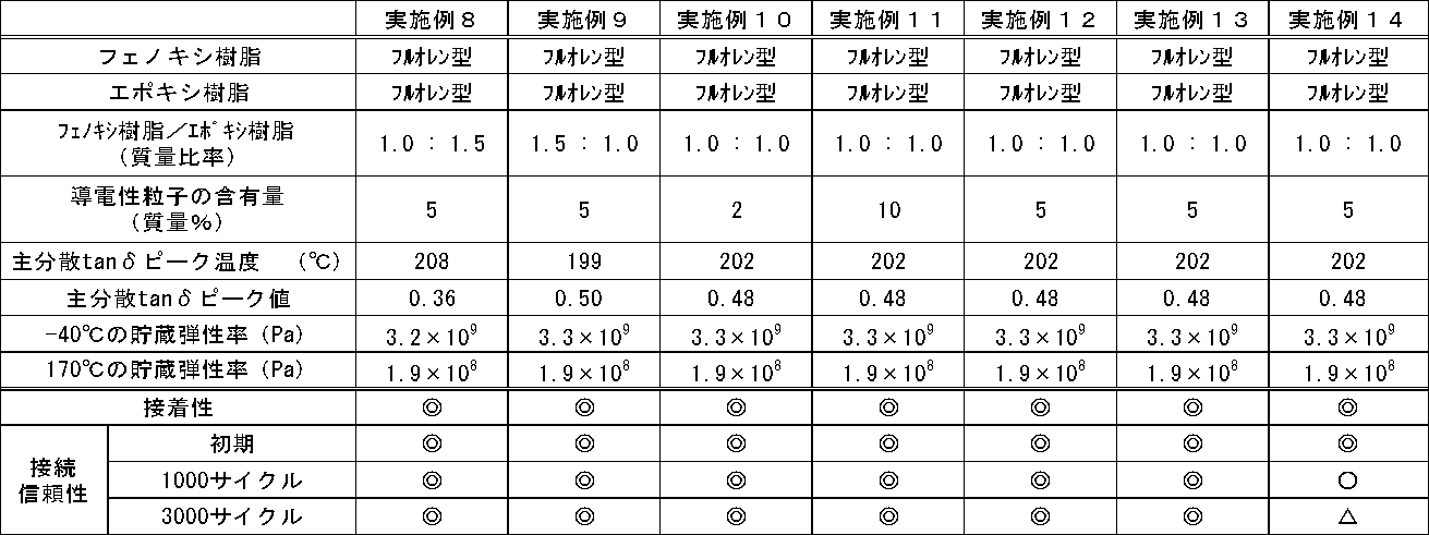

なお、比較例1、5及び6で用いたビスフェノール型フェノキシ樹脂は、PKHH(InChem社製)である。
比較例2~4で用いたフルオレン型フェノキシ樹脂は、FX293(新日鉄化学株式会社製)である。
比較例1で用いたフルオレン型エポキシ樹脂は、オクゾールCG50(大阪ガスケミカル株式会社製)である。
比較例2及び6で用いたナフタレン型エポキシ樹脂は、HP4710(DIC株式会社製)である。
比較例3で用いたフェノールノボラック型エポキシ樹脂は、N540(DIC株式会社製)である。
比較例4及び5で用いたビスフェノールA型エポキシ樹脂は、YL980(三菱化学株式会社製)である。
比較例2~4で用いたフルオレン型フェノキシ樹脂は、FX293(新日鉄化学株式会社製)である。
比較例1で用いたフルオレン型エポキシ樹脂は、オクゾールCG50(大阪ガスケミカル株式会社製)である。
比較例2及び6で用いたナフタレン型エポキシ樹脂は、HP4710(DIC株式会社製)である。
比較例3で用いたフェノールノボラック型エポキシ樹脂は、N540(DIC株式会社製)である。
比較例4及び5で用いたビスフェノールA型エポキシ樹脂は、YL980(三菱化学株式会社製)である。
実施例1~14で作製した太陽電池モジュールモデルは、接着性及び接続信頼性が優れていることが確認できた。
フルオレン型フェノキシ樹脂(A)とフルオレン型エポキシ樹脂(B)との質量比率(A:B)としては、接着性及び接続信頼性の両方が非常に優れることから、1.0:1.5~1.5:1.0が特に好ましいことが確認できた(例えば、実施例1、8及び9参照)。
導電性粒子の含有量としては、接着性及び接続信頼性の両方が非常に優れることから、2質量部~10質量部が特に好ましいことが確認できた(例えば、実施例1、10及び11参照)。
導電性粒子の種類としては、接着性及び接続信頼性の両方が非常に優れることから、銀コート銅粉が特に好ましいことが確認できた(例えば、実施例1参照)。
一方、フェノキシ樹脂及びエポキシ樹脂のいずれかにフルオレン型ではない樹脂を用いた比較例1~6では、接着性及び接続信頼性の少なくともいずれかが不十分(評価基準の「×」)であった。
フルオレン型フェノキシ樹脂(A)とフルオレン型エポキシ樹脂(B)との質量比率(A:B)としては、接着性及び接続信頼性の両方が非常に優れることから、1.0:1.5~1.5:1.0が特に好ましいことが確認できた(例えば、実施例1、8及び9参照)。
導電性粒子の含有量としては、接着性及び接続信頼性の両方が非常に優れることから、2質量部~10質量部が特に好ましいことが確認できた(例えば、実施例1、10及び11参照)。
導電性粒子の種類としては、接着性及び接続信頼性の両方が非常に優れることから、銀コート銅粉が特に好ましいことが確認できた(例えば、実施例1参照)。
一方、フェノキシ樹脂及びエポキシ樹脂のいずれかにフルオレン型ではない樹脂を用いた比較例1~6では、接着性及び接続信頼性の少なくともいずれかが不十分(評価基準の「×」)であった。
本発明の太陽電池モジュールは、接着性及び接続信頼性に優れることから、耐久性が要求される太陽電池モジュールに特に好適に用いることができる。
1 結晶系太陽電池モジュール
2 結晶系太陽電池セル
3 タブ線
4 ストリングス
5 マトリクス
6 シート
7 表面カバー
8 バックシート
9 金属フレーム
10 結晶系光電変換素子
11 バスバー電極
12 フィンガー電極
13 Al裏面電極
17 導電性接着フィルム
32 薄膜系太陽電池セル
38 基材
200 薄膜系太陽電池モジュール
2 結晶系太陽電池セル
3 タブ線
4 ストリングス
5 マトリクス
6 シート
7 表面カバー
8 バックシート
9 金属フレーム
10 結晶系光電変換素子
11 バスバー電極
12 フィンガー電極
13 Al裏面電極
17 導電性接着フィルム
32 薄膜系太陽電池セル
38 基材
200 薄膜系太陽電池モジュール
Claims (8)
- 太陽電池セルの電極とタブ線とを接続させるために用いられ、
フルオレン型フェノキシ樹脂と、フルオレン型エポキシ樹脂と、硬化剤と、導電性粒子とを少なくとも含有することを特徴とする太陽電池用導電性接着剤。 - フルオレン型フェノキシ樹脂(A)と、フルオレン型エポキシ樹脂(B)との質量比率(A:B)が、1.0:3.0~3.0:1.0である請求項1に記載の太陽電池用導電性接着剤。
- 導電性粒子の含有量が、2質量%~25質量%である請求項1から2のいずれかに記載の太陽電池用導電性接着剤。
- 硬化後の-40℃での貯蔵弾性率が、3.0×10⁹Pa~4.1×10⁹Paであり、硬化後の170℃での貯蔵弾性率が、1.9×10⁸Pa~2.2×10⁸Paである請求項1から3のいずれかに記載の太陽電池用導電性接着剤。
- 硬化後の主分散tanδピークの温度が、190℃以上であり、硬化後の主分散tanδピーク値が、0.40以上である請求項1から4のいずれかに記載の太陽電池用導電性接着剤。
- 導電性粒子が、銀コート銅粉である請求項1から5のいずれかに記載の太陽電池用導電性接着剤。
- 電極を有する太陽電池セルと、タブ線と、導電性接着剤の硬化物とを有し、
前記太陽電池セルの電極と前記タブ線とが、前記導電性接着剤の硬化物を用いて接続され、
前記導電性接着剤が、請求項1から6のいずれかに記載の太陽電池用導電性接着剤であることを特徴とする太陽電池モジュール。 - 電極を有する太陽電池セルの前記電極上に、加熱により導電性接着剤が硬化して形成される硬化物を介して前記電極とタブ線とが接続されるように、前記導電性接着剤及び前記タブ線を配置する配置工程と、
前記太陽電池セルを封止用樹脂により覆い、更に前記封止用樹脂を防湿性バックシート及びガラスプレートのいずれかにより覆う被覆工程と、
前記防湿性バックシート及びガラスプレートのいずれかを押圧する押圧工程と、
前記太陽電池セルが載置された加熱ステージを加熱する加熱工程と、を少なくとも含み、
前記導電性接着剤が、請求項1から6のいずれかに記載の太陽電池用導電性接着剤であることを特徴とする太陽電池モジュールの製造方法。
Priority Applications (2)
| Application Number | Priority Date | Filing Date | Title |
|---|---|---|---|
| CN201380035411.8A CN104412392A (zh) | 2012-07-09 | 2013-06-25 | 太阳能电池用导电性粘接剂以及太阳能电池模块及其制造方法 |
| KR20157003029A KR20150032572A (ko) | 2012-07-09 | 2013-06-25 | 태양 전지용 도전성 접착제, 및 태양 전지 모듈, 및 그의 제조 방법 |
Applications Claiming Priority (2)
| Application Number | Priority Date | Filing Date | Title |
|---|---|---|---|
| JP2012153656A JP5877133B2 (ja) | 2012-07-09 | 2012-07-09 | 太陽電池用導電性接着剤、並びに太陽電池モジュール、及びその製造方法 |
| JP2012-153656 | 2012-07-09 |
Publications (1)
| Publication Number | Publication Date |
|---|---|
| WO2014010404A1 true WO2014010404A1 (ja) | 2014-01-16 |
Family
ID=49915870
Family Applications (1)
| Application Number | Title | Priority Date | Filing Date |
|---|---|---|---|
| PCT/JP2013/067310 Ceased WO2014010404A1 (ja) | 2012-07-09 | 2013-06-25 | 太陽電池用導電性接着剤、並びに太陽電池モジュール、及びその製造方法 |
Country Status (5)
| Country | Link |
|---|---|
| JP (1) | JP5877133B2 (ja) |
| KR (1) | KR20150032572A (ja) |
| CN (1) | CN104412392A (ja) |
| TW (1) | TW201410838A (ja) |
| WO (1) | WO2014010404A1 (ja) |
Cited By (1)
| Publication number | Priority date | Publication date | Assignee | Title |
|---|---|---|---|---|
| TWI659079B (zh) * | 2014-02-03 | 2019-05-11 | 日商迪睿合股份有限公司 | Method for measuring reaction rate of acrylic adhesive and acrylic adhesive |
Families Citing this family (4)
| Publication number | Priority date | Publication date | Assignee | Title |
|---|---|---|---|---|
| JP6175935B2 (ja) * | 2013-06-25 | 2017-08-09 | 日立化成株式会社 | 太陽電池用接続材料、これを用いた太陽電池モジュール及びその製造方法 |
| CN106018965B (zh) * | 2016-05-16 | 2018-11-23 | 云南瑞博检测技术股份有限公司 | 一种光学玻璃上制备的精密电阻的检测方法 |
| JP6438102B2 (ja) * | 2017-10-19 | 2018-12-12 | デクセリアルズ株式会社 | 接続体、及び接続体の製造方法 |
| KR20230157294A (ko) * | 2021-03-05 | 2023-11-16 | 가부시끼가이샤 레조낙 | 필름상 접착제, 다이싱·다이본딩 일체형 필름, 및 반도체장치 및 그 제조 방법 |
Citations (4)
| Publication number | Priority date | Publication date | Assignee | Title |
|---|---|---|---|---|
| JP2008135654A (ja) * | 2006-11-29 | 2008-06-12 | Sanyo Electric Co Ltd | 太陽電池モジュール |
| WO2008152711A1 (ja) * | 2007-06-13 | 2008-12-18 | Hitachi Chemical Company, Ltd. | 回路接続用フィルム状接着剤 |
| JP2011032491A (ja) * | 2010-11-09 | 2011-02-17 | Sony Chemical & Information Device Corp | 異方性導電フィルム |
| JP2012074288A (ja) * | 2010-09-29 | 2012-04-12 | Yokohama Rubber Co Ltd:The | 導電性組成物および太陽電池セル |
-
2012
- 2012-07-09 JP JP2012153656A patent/JP5877133B2/ja active Active
-
2013
- 2013-06-25 WO PCT/JP2013/067310 patent/WO2014010404A1/ja not_active Ceased
- 2013-06-25 CN CN201380035411.8A patent/CN104412392A/zh active Pending
- 2013-06-25 KR KR20157003029A patent/KR20150032572A/ko not_active Withdrawn
- 2013-07-02 TW TW102123656A patent/TW201410838A/zh unknown
Patent Citations (4)
| Publication number | Priority date | Publication date | Assignee | Title |
|---|---|---|---|---|
| JP2008135654A (ja) * | 2006-11-29 | 2008-06-12 | Sanyo Electric Co Ltd | 太陽電池モジュール |
| WO2008152711A1 (ja) * | 2007-06-13 | 2008-12-18 | Hitachi Chemical Company, Ltd. | 回路接続用フィルム状接着剤 |
| JP2012074288A (ja) * | 2010-09-29 | 2012-04-12 | Yokohama Rubber Co Ltd:The | 導電性組成物および太陽電池セル |
| JP2011032491A (ja) * | 2010-11-09 | 2011-02-17 | Sony Chemical & Information Device Corp | 異方性導電フィルム |
Cited By (1)
| Publication number | Priority date | Publication date | Assignee | Title |
|---|---|---|---|---|
| TWI659079B (zh) * | 2014-02-03 | 2019-05-11 | 日商迪睿合股份有限公司 | Method for measuring reaction rate of acrylic adhesive and acrylic adhesive |
Also Published As
| Publication number | Publication date |
|---|---|
| CN104412392A (zh) | 2015-03-11 |
| KR20150032572A (ko) | 2015-03-26 |
| JP5877133B2 (ja) | 2016-03-02 |
| TW201410838A (zh) | 2014-03-16 |
| JP2014017368A (ja) | 2014-01-30 |
Similar Documents
| Publication | Publication Date | Title |
|---|---|---|
| CN103890966B (zh) | 导电性粘接剂以及使用该导电性粘接剂的太阳能电池模块及其制造方法 | |
| JP5875867B2 (ja) | 導電性接着剤、太陽電池及びその製造方法、並びに太陽電池モジュール | |
| JP5446420B2 (ja) | 太陽電池モジュール及びその製造方法 | |
| JP5877133B2 (ja) | 太陽電池用導電性接着剤、並びに太陽電池モジュール、及びその製造方法 | |
| JP5960408B2 (ja) | 導電性接着剤、太陽電池モジュール、及び太陽電池モジュールの製造方法 | |
| TW200834943A (en) | Solar cell module | |
| CN107980179B (zh) | 窄正面母线上具有正面母线胶带的光伏电池 | |
| CN105097068B (zh) | 导电胶、太阳能电池串及其制备方法 | |
| CN109659068B (zh) | 全铝背场晶体硅太阳能电池用低温固化型背面银浆 | |
| JP5889738B2 (ja) | 太陽電池モジュール及びその製造方法 | |
| JP2016048807A (ja) | 導電性接着剤、並びに、それを用いた太陽電池モジュール、及びその製造方法 | |
| JP2016178312A (ja) | 太陽電池用導電性接着剤及びこれを用いた接続方法、太陽電池モジュール、太陽電池モジュールの製造方法 | |
| KR101400133B1 (ko) | 은 페이스트 조성물 및 이를 이용하여 제조된 태양전지 | |
| JP2016160415A (ja) | 導電性組成物、太陽電池セルおよび太陽電池モジュール | |
| TWI537985B (zh) | A conductive adhesive for a solar cell and a method of connecting the solar cell module and a solar cell module using the same | |
| JP5844091B2 (ja) | 導電性組成物、太陽電池セルおよび太陽電池モジュール | |
| CN103563011A (zh) | 导电材料 | |
| CN116913576A (zh) | 导电浆料和异质结太阳能电池 | |
| JP5692347B2 (ja) | 導電接着剤 | |
| CN103943167B (zh) | 一种Ag(V,Nb)/稀土晶体硅太阳电池合金浆料及其制备方法 | |
| CN103943166B (zh) | 一种Ag(Pb,Sn)/稀土晶体硅太阳电池复合浆料及其制备方法 | |
| HK1196710A (en) | Conductive adhesive, solar cell module using same, and method for manufacturing solar cell module | |
| HK1195671A (en) | Solar cell conductive adhesive and connection method using same, solar cell module, and method for producing solar cell module | |
| HK1187153A (zh) | 太阳能电池模块及太阳能电池模块的制造方法 | |
| JP2017188620A (ja) | 接続部付太陽電池セル及び太陽電池モジュール |
Legal Events
| Date | Code | Title | Description |
|---|---|---|---|
| 121 | Ep: the epo has been informed by wipo that ep was designated in this application |
Ref document number: 13816406 Country of ref document: EP Kind code of ref document: A1 |
|
| NENP | Non-entry into the national phase |
Ref country code: DE |
|
| ENP | Entry into the national phase |
Ref document number: 20157003029 Country of ref document: KR Kind code of ref document: A |
|
| 122 | Ep: pct application non-entry in european phase |
Ref document number: 13816406 Country of ref document: EP Kind code of ref document: A1 |