WO2014010364A1 - 車両の運転席用シート装置 - Google Patents
車両の運転席用シート装置 Download PDFInfo
- Publication number
- WO2014010364A1 WO2014010364A1 PCT/JP2013/066312 JP2013066312W WO2014010364A1 WO 2014010364 A1 WO2014010364 A1 WO 2014010364A1 JP 2013066312 W JP2013066312 W JP 2013066312W WO 2014010364 A1 WO2014010364 A1 WO 2014010364A1
- Authority
- WO
- WIPO (PCT)
- Prior art keywords
- seat
- driver
- armrest
- vehicle
- cushion
- Prior art date
- Legal status (The legal status is an assumption and is not a legal conclusion. Google has not performed a legal analysis and makes no representation as to the accuracy of the status listed.)
- Ceased
Links
Images



Classifications
-
- B—PERFORMING OPERATIONS; TRANSPORTING
- B60—VEHICLES IN GENERAL
- B60N—SEATS SPECIALLY ADAPTED FOR VEHICLES; VEHICLE PASSENGER ACCOMMODATION NOT OTHERWISE PROVIDED FOR
- B60N2/00—Seats specially adapted for vehicles; Arrangement or mounting of seats in vehicles
- B60N2/02—Seats specially adapted for vehicles; Arrangement or mounting of seats in vehicles the seat or part thereof being movable, e.g. adjustable
- B60N2/04—Seats specially adapted for vehicles; Arrangement or mounting of seats in vehicles the seat or part thereof being movable, e.g. adjustable the whole seat being movable
- B60N2/06—Seats specially adapted for vehicles; Arrangement or mounting of seats in vehicles the seat or part thereof being movable, e.g. adjustable the whole seat being movable slidable
-
- B—PERFORMING OPERATIONS; TRANSPORTING
- B60—VEHICLES IN GENERAL
- B60N—SEATS SPECIALLY ADAPTED FOR VEHICLES; VEHICLE PASSENGER ACCOMMODATION NOT OTHERWISE PROVIDED FOR
- B60N2/00—Seats specially adapted for vehicles; Arrangement or mounting of seats in vehicles
- B60N2/02—Seats specially adapted for vehicles; Arrangement or mounting of seats in vehicles the seat or part thereof being movable, e.g. adjustable
- B60N2/04—Seats specially adapted for vehicles; Arrangement or mounting of seats in vehicles the seat or part thereof being movable, e.g. adjustable the whole seat being movable
- B60N2/14—Seats specially adapted for vehicles; Arrangement or mounting of seats in vehicles the seat or part thereof being movable, e.g. adjustable the whole seat being movable rotatable, e.g. to permit easy access
-
- B—PERFORMING OPERATIONS; TRANSPORTING
- B60—VEHICLES IN GENERAL
- B60N—SEATS SPECIALLY ADAPTED FOR VEHICLES; VEHICLE PASSENGER ACCOMMODATION NOT OTHERWISE PROVIDED FOR
- B60N2/00—Seats specially adapted for vehicles; Arrangement or mounting of seats in vehicles
- B60N2/24—Seats specially adapted for vehicles; Arrangement or mounting of seats in vehicles for particular purposes or particular vehicles
- B60N2/245—Seats specially adapted for vehicles; Arrangement or mounting of seats in vehicles for particular purposes or particular vehicles for handicapped persons
-
- B—PERFORMING OPERATIONS; TRANSPORTING
- B60—VEHICLES IN GENERAL
- B60N—SEATS SPECIALLY ADAPTED FOR VEHICLES; VEHICLE PASSENGER ACCOMMODATION NOT OTHERWISE PROVIDED FOR
- B60N2/00—Seats specially adapted for vehicles; Arrangement or mounting of seats in vehicles
- B60N2/75—Arm-rests
- B60N2/753—Arm-rests movable to an inoperative position
-
- A—HUMAN NECESSITIES
- A61—MEDICAL OR VETERINARY SCIENCE; HYGIENE
- A61G—TRANSPORT, PERSONAL CONVEYANCES, OR ACCOMMODATION SPECIALLY ADAPTED FOR PATIENTS OR DISABLED PERSONS; OPERATING TABLES OR CHAIRS; CHAIRS FOR DENTISTRY; FUNERAL DEVICES
- A61G3/00—Ambulance aspects of vehicles; Vehicles with special provisions for transporting patients or disabled persons, or their personal conveyances, e.g. for facilitating access of, or for loading, wheelchairs
- A61G3/02—Loading or unloading personal conveyances; Facilitating access of patients or disabled persons to, or exit from, vehicles
- A61G3/06—Transfer using ramps, lifts or the like
- A61G3/062—Transfer using ramps, lifts or the like using lifts connected to the vehicle
-
- B—PERFORMING OPERATIONS; TRANSPORTING
- B60—VEHICLES IN GENERAL
- B60N—SEATS SPECIALLY ADAPTED FOR VEHICLES; VEHICLE PASSENGER ACCOMMODATION NOT OTHERWISE PROVIDED FOR
- B60N2205/00—General mechanical or structural details
- B60N2205/30—Seat or seat parts characterised by comprising plural parts or pieces
Definitions
- the present invention relates to a vehicle seat device for a driver's seat capable of moving a seat body on which a passenger with a physical disability is seated between a driver's seat position and a passenger's boarding / exiting position in a passenger compartment.
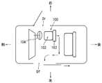
- the driver seat device 100 has a mechanism that slides the seat body 102 at the right front position (driver seat position) in the passenger compartment back to a fixed position and further slides the seat body 102 to the left side of the passenger compartment. It has. Then, the driver seat device 100 slides the seat main body 102 horizontally slid to the left side of the passenger compartment by a predetermined amount, and further horizontally rotates in the direction of the left entrance / exit Df, and from the entrance Df to the outside of the passenger compartment. It is configured to move. As a result, the seat body 102 at the driver's seat position can be moved out of the passenger compartment without interfering with the handle 104.
- the above-described vehicle seat device for a driver's seat is configured such that the seat body 102 at the right front position in the passenger compartment is slid laterally to the left side of the passenger compartment and moved out of the passenger compartment from the left entrance / exit Df. Therefore, it takes a long time for passengers to get on and off. In order to shorten the boarding / alighting time, it is preferable that the passenger can get on and off the boarding / exiting port Dr on the driver's seat side.
- a driver's seat device for a vehicle includes a seat body for the driver's seat, an armrest, and a seat moving device, and the seat body for the driver's seat includes a seat cushion and a seat back.
- the seat back is fixed at the position of the driver's seat in the passenger compartment, the seat cushion is configured to be movable separately from the seat back, and the armrest is coupled to the seat cushion.
- the seat moving device can move the seat cushion of the seat body between the driver seat position and the boarding / exiting position outside the passenger compartment by using a driver's seat side entrance / exit.
- the seat body for the driver's seat can be separated from the seat cushion fixed to the driver's seat position in the passenger compartment. For this reason, the seat cushion separated from the seat back does not interfere with the handle. Then, the seat cushion can be moved between the driver's seat position and the boarding / alighting position outside the passenger compartment through the entrance / exit on the driver's seat side by the seat moving device.
- the occupant can get into the driver's seat from the entrance / exit on the driver's side while sitting on the seat cushion, or get off the driver's seat.
- the boarding / alighting time to the driver's seat of a vehicle can be shortened compared with the driver's seat device for the conventional vehicle.
- the armrest is provided in the seat cushion, even if the seat cushion is separated from the seat back, the seating posture of the occupant is stabilized by the occupant gripping the armrest.
- the armrest is configured to be rotatable in the vertical direction between the use position and the storage position. For this reason, when not using the armrest, the armrest does not get in the way by storing it in the storage position. Furthermore, since the armrest rotates in the vertical direction, the space required to move the armrest between the use position and the storage position can be reduced.
- the seat movement device includes a rotation mechanism that horizontally rotates the seat cushion of the seat body at the driver's seat position in a direction facing the entrance / exit on the driver's seat side, and the armrest is operated by the seat cushion. It is provided on the side away from the handle when it rotates horizontally in the direction facing the entrance on the seat side. For this reason, the armrest does not interfere with the handle when the seat cushion is horizontally rotated from the driver's seat position toward the driver's seat entrance / exit.
- the seat moving device is configured to be operable with the armrest in the use position. That is, when the armrest is in the standby position, the seat moving device does not operate. Therefore, when the seat cushion is moving between the driver's seat position in the passenger compartment and the entry / exit position outside the passenger compartment, the armrest is always in the use position, so that the passenger can safely get on and off by gripping the armrest. Become.
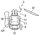
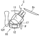
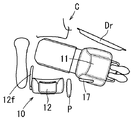
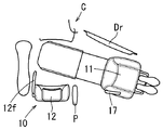
- FIG. 6 is a schematic plan view illustrating a movement operation of a seat cushion of the driver seat device.
- FIG. 6 is a schematic plan view illustrating a movement operation of a seat cushion of the driver seat device.
- FIG. 6 is a schematic plan view illustrating a movement operation of a seat cushion of the driver seat device.
- FIG. 6 is a schematic plan view illustrating a movement operation of a seat cushion of the driver seat device.
- FIG. 6 is a schematic plan view illustrating a movement operation of a seat cushion of the driver seat device. It is a schematic top view showing the movement operation
- the vehicle seat device for a driver's seat according to the present embodiment is used when a passenger with a physical disability gets on and off the driver's seat of the vehicle.
- front and rear, right and left and up and down in the figure correspond to front and rear, left and right and up and down of the vehicle.
- the driver seat device S is used as a driver seat of the vehicle C and includes a seat body 10 and a seat moving device 200.
- the seat moving device 200 moves the seat cushion 11 of the seat body 10 between a driver seat position in the vehicle interior and a boarding / alighting position outside the vehicle interior.
- the seat body 10 includes a seat cushion 11, a seat back 12, a seat cushion frame 15 (see FIG. 2 and the like), and a seat back frame (not shown).
- the seat cushion 11 and the seat back 12 of the seat body 10 are separable.
- the seat back 12 is installed at a driver seat position in the passenger compartment via a seat back frame (not shown).
- the seat cushion 11 is connected to the seat moving device 200 via a seat cushion frame 15.
- the seat cushion 11 is combined with the seat back 12 at the driver seat position to constitute a driver seat.
- the left armrest 12f is attached to the seatback frame of the seatback 12 as shown in FIG.
- a right armrest 17 is connected to the seat cushion frame 15 of the seat cushion 11 so as to be vertically rotatable between a use position and a standby position.
- the use position of the armrest 17 is a position where the armrest body 17m is held almost horizontally as shown in FIG. 1 and the like, and the standby position is a vertical direction so that the armrest body 17m is along the seat back 12. It is a position.
- the seat back 12 is configured to be tiltable with respect to the seat cushion 11 by a reclining mechanism (not shown).
- the seat cushion 11 since the seat cushion 11 is separated from the seat back 12 and can move independently, the seat cushion 11 does not interfere with the handle 18 during the movement.
- the seat moving device 200 for moving the seat cushion 11 includes a front / rear slide mechanism 20, a rotating mechanism 30, an elevating mechanism 50, and an outer / inner slide mechanism 70, as shown in the schematic side views of FIGS. ing.
- the front / rear slide mechanism 20 is installed on the floor F in the passenger compartment.
- the rotation mechanism 30 is installed on the front / rear slide base 21 of the front / rear slide mechanism 20.
- the elevating mechanism 50 and the outer / inner slide mechanism 70 are installed on the rotation base 35 of the rotation mechanism 30.
- the seat cushion 11 of the seat body 10 is installed on the outer / inner slide mechanism 70.
- the front / rear slide mechanism 20 of the seat moving device 200 is a mechanism that moves the seat body 10 in the vehicle front-rear direction in the vehicle interior.
- the front / rear slide mechanism 20 includes a pair of left and right fixed-side rails 22, a front / rear slide base 21, and a drive unit 24.
- the pair of left and right fixed rails 22 are installed on the fixed base 23 of the vehicle floor F so as to extend in the vehicle front-rear direction.
- the front / rear slide base 21 is supported by the stationary rails 22 in a state in which the front / rear slide base 21 can slide back and forth.
- a rotating mechanism 30 is installed on the front / rear slide base 21.
- the rotation mechanism 30 is a mechanism that horizontally rotates the seat body 10 by about 100 ° between a vehicle front-facing position and a lateral position facing the entrance / exit D (right side), and can rotate horizontally with respect to the front / rear slide base 21.
- a rotation base 35 is provided.
- An elevating mechanism 50 is installed on the rotation base 35.
- the elevating mechanism 50 is a mechanism for elevating the seat body 10 outside the passenger compartment, and includes a lateral slide mechanism 40 (see FIG. 6), a four-bar linkage mechanism 51, an elevating base 55, have.
- the horizontal slide mechanism 40 is a horizontal drive source.
- the four-bar linkage mechanism 51 rotates in the vertical direction in response to the sliding operation of the horizontal slide base 44 of the horizontal slide mechanism 40.
- the lifting base 55 is lifted and lowered by the four-bar linkage mechanism 51.
- the seat body 10 is installed on the lift base 55 via the outer / inner slide mechanism 70.
- the outer / inner slide mechanism 70 includes a seat base 75 that supports the seat body 10, and the seat base 75 is attached to the lift base 55 of the lift mechanism 50. It is configured to slide in the front-rear direction.
- the getting-off switch is operated with the right armrest 17 in the use position. Accordingly, as shown in FIGS. 7A to 7C, the rotation mechanism 30 of the seat moving device 200 rotates the seat cushion 11 of the seat body 10 clockwise. That is, in a state where the seat back 12 is fixed at the driver's seat position, only the seat cushion 11 is rotated to the right while being separated from the seat back 12. Thereby, the seat cushion 11 does not interfere with the handle 18.
- the seat cushion 11 is separated from the handle 18 and does not interfere with the handle 18 when the seat cushion 11 rotates to the right. The occupant can sit on the seat cushion 11 in a stable posture by leaning on the right armrest 17.
- the front / rear slide mechanism 20 slides the front / rear slide base 21 forward. That is, the seat cushion 11 rotates to the right (rotating slide) while moving forward. Thereby, as shown in FIG. 7C, interference between the seat cushion 11 and the center pillar P of the vehicle C is avoided.
- the outer / inner slide mechanism 70 When the seat cushion 11 rotates about 90 ° and faces the entrance / exit D, the outer / inner slide mechanism 70 operates and, as shown in FIGS. 2, 5, and 7D, the seat cushion 11 is operated. Advances with respect to the lifting base 55 of the lifting mechanism 50. As a result, the seat cushion 11 is swung out of the passenger compartment from the entrance D (outside slide).
- the four-bar link mechanism 51 rotates downward as shown in FIGS. 3, 6, and 7E.
- the seat cushion 11 moves forward together with the lifting base 55 and descends horizontally.
- the elevating mechanism 50 stops.
- the seat cushion 11 When the occupant gets on the vehicle C, the occupant seated on the seat cushion 11 sets the armrest 17 at the use position and operates the occupant switch, so that the seat moving device 200 operates in the reverse operation. As a result, the seat cushion 11 on which an occupant is placed moves to the driver seat position and constitutes a driver seat together with the seat back 12.
- the driver seat device S provides the following advantages.
- the seat body 10 for the driver's seat can be separated from the seat cushion 12 with respect to the seat back 12 fixed at the driver's seat position in the passenger compartment. For this reason, the seat cushion 11 separated from the seat back 12 does not interfere with the handle 18.
- the seat cushion 11 can be moved by the seat moving device 200 between the driver seat position and the boarding / alighting position outside the passenger compartment through the driver's seat entrance D. Therefore, the occupant can get into the driver's seat from the entrance / exit D on the driver's seat side while sitting on the seat cushion 11 or get off the driver's seat.
- the boarding / alighting time to the driver's seat of a vehicle can be shortened compared with the conventional driver's seat device.
- the armrest 17 is provided in the seat cushion 11, even if the seat cushion 11 is separated from the seat back 12, the seating posture of the occupant is stabilized by the occupant gripping the armrest 17.
- the armrest 17 rotates in the vertical direction between the use position and the storage position, the space required to move the armrest 17 between the use position and the storage position can be reduced.
- the armrest 17 is provided on the side away from the handle 18 when the seat cushion 11 rotates horizontally in a direction facing the entrance / exit D on the driver's seat side. For this reason, the armrest 17 does not interfere with the handle 18 when the seat cushion 11 is horizontally rotated from the driver's seat position toward the driver's seat entrance / exit D.
- the seat moving device 200 is configured to be operable in a state where the armrest 17 is in the use position. That is, when the armrest 17 is in the standby position, the sheet moving device 200 does not operate. Therefore, when the seat cushion 11 is moving between the driver's seat position in the passenger compartment and the entry / exit position outside the passenger compartment, the armrest 17 is always in the use position, so that the occupant leans on the armrest 17 and safely gets on and off. it can.
- the present invention is not limited to the above embodiment, and can be modified without departing from the gist of the present invention.
- the seat cushion 11 of the seat body 10 is entirely separated from the seat back 12 is shown.
- a configuration in which the seating portion (portion other than the rear end portion) of the seat back 12 is separated from the seat back 12 is also possible.
- the seat moving device 200 can operate in a state where the armrest 17 is in the use position.
- the seat moving device 200 can be operated even when the armrest 17 is in the standby position.
- the driver seat for a right-hand drive vehicle is shown, but the present invention can also be applied to a driver seat for a left-hand drive vehicle.
Landscapes
- Engineering & Computer Science (AREA)
- Aviation & Aerospace Engineering (AREA)
- Transportation (AREA)
- Mechanical Engineering (AREA)
- Seats For Vehicles (AREA)
Description
本発明は、体の不自由な乗員が着座するシート本体を車室内の運転席位置と乗降位置との間で移動させることが可能な車両の運転席用シート装置に関する。
関連する車両の運転席用シート装置が特開2007-168469号に記載されている。この運転席用シート装置100は、図8に示すように、車室内の右前位置(運転席位置)にあるシート本体102を定位置まで後スライドさせ、さらに、車室の左側まで横スライドさせる機構を備えている。そして、運転席用シート装置100は車室の左側まで横スライドされたシート本体102を一定量前スライドさせ、さらに左側の乗降口Dfの方向に水平回転させて、その乗降口Dfから車室外に移動させるように構成されている。これにより、運転席位置にあるシート本体102をハンドル104と干渉することなく車室外まで移動させられる。
しかし、上記した車両の運転席用シート装置は、車室内の右前位置にあるシート本体102を車室の左側まで横スライドして、左側の乗降口Dfから車室外に移動するように構成されているため、乗員の乗降に要する時間が長い。乗降時間短縮を図るためには、乗員が運転席側の乗降口Drから乗り降りできるようにするのが好ましい。しかし、運転席位置にあるシート本体102を乗降口Drの方向に水平右回転させるときに、シート本体102のシートバック103がハンドル104と干渉するため、シート本体102を右側の乗降口Drから車室外に移動させることはできない。故に、シートバックがハンドルに干渉することなく車室外まで移動でき、且つ乗員がより短い時間で乗降できる、運転席用シート装置が望まれている。
本発明の1つの特徴によると、車両の運転席用シート装置は、運転席用のシート本体と、アームレストと、シート移動装置とを有し、運転席用のシート本体はシートクッションとシートバックとを備えており、そのシートバックが車室内の運転席位置に固定されており、前記シートクッションが前記シートバックと分離して移動可能に構成されており、アームレストは前記シートクッションに連結されており、シート移動装置は運転席側の乗降口を利用して、前記シート本体のシートクッションを前記運転席位置と車室外の乗降位置との間で移動させることができる。
本発明によると、運転席用のシート本体は、車室内の運転席位置に固定されたシートバックに対してシートクッションが分離可能である。このため、シートバックと分離したシートクッションはハンドルと干渉しない。そして、シートクッションがシート移動装置によって運転席側の乗降口を通って運転席位置と車室外の乗降位置との間で移動できるようになる。
したがって、乗員はシートクッションに着座した状態で運転席側の乗降口から運転席に乗り込み、あるいは運転席から降りることが可能である。これにより、従来の車両の運転席用シート装置と比較して、車両の運転席への乗降時間を短縮できる。
ここで、シートクッションにはアームレストが設けられているため、シートクッションがシートバックから離れても、乗員がアームレストを把持することで乗員の着座姿勢が安定する。
別の特徴においては、アームレストは、使用位置と格納位置との間で上下方向に回動可能に構成されている。このため、アームレストを使用しないときは格納位置に格納することでそのアームレストが邪魔にならない。さらに、アームレストは上下方向に回動するため、アームレストを使用位置と格納位置との間で移動させるのに必要なスペースを小さくできる。
別の特徴においては、シート移動装置は、運転席位置にあるシート本体のシートクッションを運転席側の乗降口を向く方向に水平回転させる回転機構を備えており、アームレストは、前記シートクッションが運転席側の乗降口を向く方向に水平回転する際に、前記ハンドルから離れる側に設けられている。このため、シートクッションを運転席位置から運転席側の乗降口を向く方向に水平回転させる際に、アームレストがハンドルと干渉しない。
さらに別の特徴においては、シート移動装置は、アームレストが使用位置にある状態で動作可能に構成されている。即ち、アームレストが待機位置にある状態では、シート移動装置が動作しない。このため、シートクッションが車室内の運転席位置と車室外の乗降位置との間を移動している状態ではアームレストが必ず使用位置にあるため、乗員はアームレストを把持して安全に乗降できるようになる。
以下、図1~図7(E)に基づいて、本発明の実施形態に係る車両の運転席用シート装置の説明を行なう。本実施形態に係る車両の運転席用シート装置は、体の不自由な乗員が車両の運転席に乗降する際に使用される。ここで、図中の前後左右及び上下は、車両の前後左右及び上下に対応している。
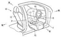
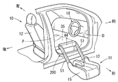
運転席用シート装置Sは、図1等に示すように、車両Cの運転席として使用され、シート本体10と、シート移動装置200とから構成されている。シート移動装置200は、シート本体10のシートクッション11を車室内の運転席位置と車室外の乗降位置との間で移動させる。
シート本体10は、図1に示すように、シートクッション11と、シートバック12と、シートクッション用フレーム15(図2等参照)と、シートバック用フレーム(図示省略)とから構成されている。シート本体10のシートクッション11とシートバック12とは分離可能である。シートバック12は、シートバック用フレーム(図示省略)を介して車室内の運転席位置に設置されている。シートクッション11は、シートクッション用フレーム15を介してシート移動装置200に連結されている。そして、シートクッション11は、図1に示すように、運転席位置で前記シートバック12と組み合わされて、運転席を構成している。
シートバック12のシートバック用フレームには、図1等に示すように、左側のアームレスト12fが取付けられている。また、シートクッション11のシートクッション用フレーム15には、右側のアームレスト17が使用位置と待機位置との間で上下回転可能な状態で連結されている。ここで、アームレスト17の使用位置とは、図1等に示すように、アームレスト本体17mがほぼ水平に保持される位置であり、待機位置とはアームレスト本体17mがシートバック12に沿うように縦向きとなる位置である。なお、運転席位置では、シートバック12はリクライニング機構(図示省略)によってシートクッション11に対して傾斜可能に構成されている。
上記のように、シートクッション11がシートバック12から分離して単独で移動可能な構成のため、そのシートクッション11が移動途中でハンドル18と干渉しない。
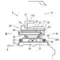
シートクッション11を移動させるシート移動装置200は、図4~図6の模式側面図に示すように、前後スライド機構20と、回転機構30と、昇降機構50と、外内スライド機構70とを備えている。前後スライド機構20は、車室内のフロアF上に設置されている。回転機構30は、前後スライド機構20の前後スライドベース21上に設置されている。昇降機構50及び外内スライド機構70は、その回転機構30の回転ベース35上に設置されている。外内スライド機構70上にシート本体10のシートクッション11が設置されている。
シート移動装置200の前後スライド機構20は、車室内でシート本体10を車両前後方向に移動させる機構である。前後スライド機構20は、図4等に示すように、左右一対の固定側レール22と、前後スライドベース21と、駆動部24とから構成されている。左右一対の固定側レール22は、車両フロアFの固定ベース23上で車両前後方向に延びるように設置されている。前後スライドベース21は、それらの固定側レール22に前後スライド可能な状態で支持される。
前後スライドベース21上には、回転機構30が設置されている。回転機構30は、シート本体10を車両前向き位置と乗降口D側(右側)を向いた横向き位置との間で約100°水平回転させる機構であり、前後スライドベース21に対して水平回転可能な回転ベース35を備えている。
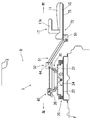
回転ベース35上には、昇降機構50が設置されている。昇降機構50は、図4~図6に示すように、車室外でシート本体10を昇降させる機構であり、横スライド機構40(図6参照)と、四節リンク機構51と、昇降ベース55とを有している。横スライド機構40は、水平方向の駆動源となる。四節リンク機構51は、横スライド機構40の横スライドベース44のスライド動作を受けて上下方向に回動する。昇降ベース55は、四節リンク機構51により昇降させられる。そして、昇降ベース55上に外内スライド機構70を介してシート本体10が設置されている。
外内スライド機構70は、図5、図6に示すように、シート本体10を支持するシート用ベース75を備えており、昇降機構50の昇降ベース55に対してシート用ベース75をシート本体10の前後方向にスライドさせるように構成されている。
次に、図5に基づいて運転席用シート装置Sの動作について説明する。運転席位置においてシート本体10に着座している乗員が降車するときには、車両Cの運転席ドアDrを開放した後、右側のアームレスト17が使用位置にある状態で降車スイッチが操作される。これにより、図7(A)~(C)に示すように、シート移動装置200の回転機構30がシート本体10のシートクッション11を右回転させる。即ち、シートバック12が運転席位置に固定されている状態で、シートバック12から分離してシートクッション11のみが右回転する。これにより、シートクッション11がハンドル18と干渉しない。さらに、シートクッション11のアームレスト17は右側にあるため、シートクッション11が右回転する際にハンドル18から離れ、ハンドル18と干渉しない。そして、乗員は右側のアームレスト17に寄り掛かることで、安定した姿勢でシートクッション11に着座できる。
このようにして、シートクッション11が一定角度右回転した後、前後スライド機構20が前後スライドベース21を前方にスライドさせる。即ち、シートクッション11は、前方に移動しつつ、右回転する(回転スライド)。これにより、図7(C)に示すように、シートクッション11と車両CのセンターピラーPとの干渉が回避される。
そして、シートクッション11が約90°回転して乗降口D側を向くと、外内スライド機構70が動作して、図2、図5、及び図7(D)に示すように、シートクッション11が昇降機構50の昇降ベース55に対して前進する。これにより、シートクッション11が乗降口Dから車室外に振出される(外スライド)。
次に、横スライド機構40の横スライドベース44が四節リンク機構51を前進させることで、図3、図6、及び図7(E)に示すように、四節リンク機構51が下方に回動し、昇降ベース55と共にシートクッション11が前進しつつ水平に下降する。そして、シートクッション11が乗降位置に到達したときに、昇降機構50が停止する。
また、乗員が車両Cに乗車するときには、シートクッション11に着座した乗員がアームレスト17を使用位置にセットして乗車スイッチを操作することで、上記と逆の動作でシート移動装置200が動作する。これにより、乗員を乗せたシートクッション11が運転席位置まで移動して、シートバック12と共に運転席を構成する。
本実施形態に係る運転席用シート装置Sは、次のような利点をもたらす。運転席用のシート本体10は、車室内の運転席位置に固定されたシートバック12に対してシートクッション11が分離可能である。このため、シートバック12から分離されたシートクッション11はハンドル18と干渉しない。そして、シートクッション11がシート移動装置200によって、運転席側の乗降口Dを通って運転席位置と車室外の乗降位置との間で移動できる。したがって、乗員はシートクッション11に着座した状態で運転席側の乗降口Dから運転席に乗り込み、あるいは運転席から降りることが可能である。これにより、従来の運転席用シート装置と比較して、車両の運転席への乗降時間を短縮できる。
ここで、シートクッション11にはアームレスト17が設けられているため、シートクッション11がシートバック12から離れても、乗員がアームレスト17を把持することで乗員の着座姿勢が安定する。
また、アームレスト17は、使用位置と格納位置との間で上下方向に回動するため、アームレスト17を使用位置と格納位置との間で移動させるのに必要なスペースを小さくできる。また、アームレスト17は、シートクッション11が運転席側の乗降口Dを向く方向に水平回転する際に、ハンドル18から離れる側に設けられている。このため、シートクッション11が運転席位置から運転席側の乗降口Dを向く方向に水平回転される際に、アームレスト17がハンドル18と干渉しない。
また、シート移動装置200は、アームレスト17が使用位置にある状態で動作可能に構成されている。即ち、アームレスト17が待機位置にある状態では、シート移動装置200は動作しない。このため、シートクッション11が車室内の運転席位置と車室外の乗降位置との間を移動している状態ではアームレスト17が必ず使用位置にあるため、乗員はアームレスト17に寄り掛かって安全に乗降できる。
ここで、本発明は上記実施形態に限定されるものではなく、本発明の要旨を逸脱しない範囲における変更が可能である。例えば、本実施形態では、シート本体10のシートクッション11を全体的にシートバック12から分離させる例が示された。しかし、シートバック12の着座部分(後端部分以外の部分)をシートバック12に対して分離させる構成でも可能である。
また、本実施形態では、アームレスト17が使用位置にある状態でシート移動装置200が動作可能である例が示された。しかし、例えば、シートクッション11に着座センサを設け、着座センサが乗員を検出しないときには、アームレスト17が待機位置にあるときでもシート移動装置200を動作させることは可能である。また、本実施形態では、右ハンドルの車両における運転席用シートが示されたが、左ハンドルの車両における運転席用シートに本発明を適用することも可能である。
Claims (4)
- 運転席用のシート本体と、アームレストと、シート移動装置とを有する車両の運転席用シート装置であって、
前記運転席用のシート本体は、シートクッションとシートバックとを備えており、前記シートバックは車室内の運転席位置に固定されており、前記シートクッションは前記シートバックと分離して移動可能に構成されており、
前記アームレストは、前記シートクッションに連結されており、
前記シート移動装置は、運転席側の乗降口を利用して、前記シート本体のシートクッションを前記運転席位置と車室外の乗降位置との間で移動させることができるようになっている車両の運転席用シート装置。 - 請求項1に記載された車両の運転席用シート装置であって、
前記アームレストは、使用位置と格納位置との間で上下方向に回動可能に構成されている車両の運転席用シート装置。 - 請求項1又は請求項2のいずれかに記載された車両の運転席用シート装置であって、
前記シート移動装置は、前記運転席位置にある前記シート本体の前記シートクッションを前記運転席側の乗降口を向く方向に水平回転させる回転機構を備えており、
前記アームレストは、前記シートクッションが前記運転席側の乗降口を向く方向に水平回転する際に、ハンドルから離れる側に設けられている車両の運転席用シート装置。 - 請求項2又は請求項3のいずれかに記載された車両の運転席用シート装置であって、
前記シート移動装置は、前記アームレストが前記使用位置にある状態で動作可能なように構成されている車両の運転席用シート装置。
Applications Claiming Priority (2)
| Application Number | Priority Date | Filing Date | Title |
|---|---|---|---|
| JP2012157528A JP2014019212A (ja) | 2012-07-13 | 2012-07-13 | 車両の運転席用シート装置 |
| JP2012-157528 | 2012-07-13 |
Publications (1)
| Publication Number | Publication Date |
|---|---|
| WO2014010364A1 true WO2014010364A1 (ja) | 2014-01-16 |
Family
ID=49915832
Family Applications (1)
| Application Number | Title | Priority Date | Filing Date |
|---|---|---|---|
| PCT/JP2013/066312 Ceased WO2014010364A1 (ja) | 2012-07-13 | 2013-06-13 | 車両の運転席用シート装置 |
Country Status (2)
| Country | Link |
|---|---|
| JP (1) | JP2014019212A (ja) |
| WO (1) | WO2014010364A1 (ja) |
Cited By (1)
| Publication number | Priority date | Publication date | Assignee | Title |
|---|---|---|---|---|
| CN108909544A (zh) * | 2018-08-17 | 2018-11-30 | 吉林大学 | 一种行动不便者使用的汽车全自动后座装置 |
Families Citing this family (12)
| Publication number | Priority date | Publication date | Assignee | Title |
|---|---|---|---|---|
| US9694292B2 (en) * | 2015-04-09 | 2017-07-04 | Philadelphia Toboggan Coasters, Inc. | Amusement ride transfer accessibility device for the physically-disabled |
| US10908045B2 (en) | 2016-02-23 | 2021-02-02 | Deka Products Limited Partnership | Mobility device |
| US11399995B2 (en) | 2016-02-23 | 2022-08-02 | Deka Products Limited Partnership | Mobility device |
| CA3278463A1 (en) | 2016-02-23 | 2025-10-27 | Deka Products Limited Partnership | Mobility device control system |
| US10926756B2 (en) | 2016-02-23 | 2021-02-23 | Deka Products Limited Partnership | Mobility device |
| EP3443426B1 (en) | 2016-04-14 | 2022-10-26 | DEKA Products Limited Partnership | A transporter and a control method for a transporter |
| TWM528164U (zh) * | 2016-04-28 | 2016-09-11 | Hong-Huan Xu | 輪椅與汽車座椅之結合機構 |
| USD846452S1 (en) | 2017-05-20 | 2019-04-23 | Deka Products Limited Partnership | Display housing |
| JP6928805B2 (ja) * | 2017-09-20 | 2021-09-01 | トヨタ車体株式会社 | 車両用シート装置 |
| JP2021527204A (ja) | 2018-06-07 | 2021-10-11 | デカ・プロダクツ・リミテッド・パートナーシップ | 配送多目的サービス実行のためのシステムおよび方法 |
| KR102898358B1 (ko) | 2020-02-24 | 2025-12-10 | 현대자동차주식회사 | 차량용 암레스트장치 및 이의 작동 제어방법 |
| US20250222833A1 (en) * | 2024-01-04 | 2025-07-10 | GM Global Technology Operations LLC | Vehicle seats and methods for promoting access to a vehicle |
Citations (5)
| Publication number | Priority date | Publication date | Assignee | Title |
|---|---|---|---|---|
| JPH07213557A (ja) * | 1993-12-01 | 1995-08-15 | Hoover Universal Inc | 車両シ−ト構体 |
| JPH10297328A (ja) * | 1997-04-23 | 1998-11-10 | Kanto Auto Works Ltd | 回転リヤシートの構造 |
| JPH10315964A (ja) * | 1997-05-19 | 1998-12-02 | Kinki Sharyo Co Ltd | 車両用簡易回転シート |
| JPH1111190A (ja) * | 1997-06-19 | 1999-01-19 | Nissan Motor Co Ltd | 車両用座席装置 |
| JP2005034326A (ja) * | 2003-07-18 | 2005-02-10 | Toyota Auto Body Co Ltd | シート装置およびこれを用いた車両用シート |
-
2012
- 2012-07-13 JP JP2012157528A patent/JP2014019212A/ja active Pending
-
2013
- 2013-06-13 WO PCT/JP2013/066312 patent/WO2014010364A1/ja not_active Ceased
Patent Citations (5)
| Publication number | Priority date | Publication date | Assignee | Title |
|---|---|---|---|---|
| JPH07213557A (ja) * | 1993-12-01 | 1995-08-15 | Hoover Universal Inc | 車両シ−ト構体 |
| JPH10297328A (ja) * | 1997-04-23 | 1998-11-10 | Kanto Auto Works Ltd | 回転リヤシートの構造 |
| JPH10315964A (ja) * | 1997-05-19 | 1998-12-02 | Kinki Sharyo Co Ltd | 車両用簡易回転シート |
| JPH1111190A (ja) * | 1997-06-19 | 1999-01-19 | Nissan Motor Co Ltd | 車両用座席装置 |
| JP2005034326A (ja) * | 2003-07-18 | 2005-02-10 | Toyota Auto Body Co Ltd | シート装置およびこれを用いた車両用シート |
Cited By (2)
| Publication number | Priority date | Publication date | Assignee | Title |
|---|---|---|---|---|
| CN108909544A (zh) * | 2018-08-17 | 2018-11-30 | 吉林大学 | 一种行动不便者使用的汽车全自动后座装置 |
| CN108909544B (zh) * | 2018-08-17 | 2024-05-17 | 吉林大学 | 一种行动不便者使用的汽车全自动后座装置 |
Also Published As
| Publication number | Publication date |
|---|---|
| JP2014019212A (ja) | 2014-02-03 |
Similar Documents
| Publication | Publication Date | Title |
|---|---|---|
| WO2014010364A1 (ja) | 車両の運転席用シート装置 | |
| CN102328605B (zh) | 车辆用座椅的控制装置 | |
| JP6675276B2 (ja) | 車両用シート装置 | |
| US8827367B2 (en) | Vehicle seat | |
| US8398356B2 (en) | Automotive wheelchair mobility system | |
| EP2455254A1 (en) | Vehicle seat | |
| JP6928805B2 (ja) | 車両用シート装置 | |
| JP4352971B2 (ja) | フットレスト装置およびオットマン装置付き乗物用シートの制御方法 | |
| JP6346226B2 (ja) | 車両用シート制御装置 | |
| JP7821551B2 (ja) | 車両用シート装置 | |
| JP5655227B2 (ja) | 車両のシート駆動装置 | |
| JP5888155B2 (ja) | 車両用シート装置 | |
| JP4720416B2 (ja) | 車両用シート | |
| JP5193126B2 (ja) | 車椅子乗車可能な自動車 | |
| JP5771538B2 (ja) | 自動車に用いる折りたたみシート | |
| JP7312090B2 (ja) | 乗降制御装置 | |
| JP3578093B2 (ja) | 車両用シート | |
| JP4244773B2 (ja) | 車両用シート | |
| JP2005145281A (ja) | 車両の乗降補助装置 | |
| JP7420455B2 (ja) | 車両用シート | |
| JP7592358B2 (ja) | 車両用シート装置 | |
| JP2019155964A (ja) | 車両用ステップ構造 | |
| JP5493592B2 (ja) | 車両用シート | |
| JP4389832B2 (ja) | 車両用シート | |
| JP2014088088A (ja) | 車両用シート装置 |
Legal Events
| Date | Code | Title | Description |
|---|---|---|---|
| 121 | Ep: the epo has been informed by wipo that ep was designated in this application |
Ref document number: 13816804 Country of ref document: EP Kind code of ref document: A1 |
|
| NENP | Non-entry into the national phase |
Ref country code: DE |
|
| 122 | Ep: pct application non-entry in european phase |
Ref document number: 13816804 Country of ref document: EP Kind code of ref document: A1 |