WO2014010179A1 - 車両用視界支援装置 - Google Patents
車両用視界支援装置 Download PDFInfo
- Publication number
- WO2014010179A1 WO2014010179A1 PCT/JP2013/003851 JP2013003851W WO2014010179A1 WO 2014010179 A1 WO2014010179 A1 WO 2014010179A1 JP 2013003851 W JP2013003851 W JP 2013003851W WO 2014010179 A1 WO2014010179 A1 WO 2014010179A1
- Authority
- WO
- WIPO (PCT)
- Prior art keywords
- mask
- vehicle
- transmittance
- image
- end line
- Prior art date
- Legal status (The legal status is an assumption and is not a legal conclusion. Google has not performed a legal analysis and makes no representation as to the accuracy of the status listed.)
- Ceased
Links
Images



Classifications
-
- H—ELECTRICITY
- H04—ELECTRIC COMMUNICATION TECHNIQUE
- H04N—PICTORIAL COMMUNICATION, e.g. TELEVISION
- H04N7/00—Television systems
- H04N7/18—Closed-circuit television [CCTV] systems, i.e. systems in which the video signal is not broadcast
- H04N7/183—Closed-circuit television [CCTV] systems, i.e. systems in which the video signal is not broadcast for receiving images from a single remote source
Definitions
- the present disclosure relates to a vehicular visibility support device.
- Patent Document 1 discloses a technique for acquiring a captured image from an in-vehicle camera that captures the periphery of a vehicle and displaying a mask transparently on the acquired captured image.
- the risk prediction region is emphasized by transparently superimposing a mask outside the risk prediction region, and the transmittance is changed according to the risk level of the risk prediction region, the vehicle speed of the host vehicle, and the like. I am letting.
- the present disclosure relates to a technique for acquiring a captured image from an in-vehicle camera that captures the surroundings of a vehicle, and transparently displaying a mask on the acquired captured image of a light emitter around a road (for example, a lighting device attached to a building).
- the purpose is to reduce the possibility that the driver of the vehicle will be dazzled by light.
- an acquisition section that acquires a captured image from an in-vehicle camera that captures the surroundings of the vehicle, and a representative value of luminance in a predetermined detection region in the captured image is small.
- a transmittance setting section for setting the transmittance as small as possible, a superposition section for superimposing the mask of transmittance on the mask area in the display image based on the acquired captured image, and the mask transparently superimposed on the mask
- a display control section for displaying a display image on a display unit.
- the vehicle vision support system is mounted on a vehicle and, as shown in FIG. 1, an in-vehicle camera 1, an ECU 2 (corresponding to an example of an Electronic Control Unit, a vehicle vision support device), and a display unit 3 It has.
- the in-vehicle camera 1 is fixedly mounted in the vicinity of the rear end of the vehicle.
- the vehicle-mounted camera 1 has a predetermined range behind the vehicle (for example, a range in which the driver can see with a normal room mirror). Images are taken repeatedly (for example, at a cycle of 1/30 seconds), and video signals of the captured images in the predetermined range obtained as a result of the shooting are sequentially output to the ECU 2.
- the ECU 2 is configured to repeatedly input the above-described captured image from the in-vehicle camera 1 and repeatedly input vehicle speed information and shift range information from the vehicle. Then, the ECU 2 superimposes a gradation mask on the captured image input from the in-vehicle camera 1 and inputs the video signal of the captured image after superimposition to the display unit 3.
- ECU2 may be a microcomputer provided with CPU, RAM, ROM, and I / O, for example.
- the display unit 3 is a device that displays a photographed image represented by a video signal input from the ECU 2, and a position at which a driver in the vehicle can see the displayed photographed image (for example, a position of a room mirror, a dashboard) At the center of the door, the position of the door mirror, etc.).
- each section is expressed as S100, for example.
- each section can be divided into a plurality of subsections, while a plurality of sections can be combined into one section.
- each section configured in this manner can be referred to as a device, module, or means.
- ECU 2 (in other words, CPU) first activates the in-vehicle camera 1 in S110. Accordingly, the in-vehicle camera 1 repeatedly captures a predetermined range behind the vehicle, and sequentially outputs a video signal of a captured image in the predetermined range obtained as a result of the imaging to the ECU 2.
- the ECU 2 starts to repeatedly execute the processes of S120 to S160.
- vehicle speed information and shift position information are acquired from the vehicle as vehicle information.
- the video signal of the latest photographed image is acquired from the in-vehicle camera 1.
- Various corrections are performed on the captured image represented by the video signal, and the corrected captured image is used as a display image.
- the correction includes trimming that cuts out and discards the top, bottom, left, and right edges of the photographed image, and distortion correction that corrects distortion.
- the corrected display image corresponds to an example of a display image based on the captured image.
- a specification of a mask image (hereinafter referred to as a gradation mask) is generated.
- a gradation mask according to the generated specification is created, and the created gradation mask is applied to a mask target range in the display image. Is transparently superimposed on.
- the gradation mask GM will be described with reference to FIG. 3, in S150, the ECU 2 uses the entire range from the predetermined mask lower end line ML to the mask upper end line MU in the display image 10 as a mask region, and the gradation mask GM having the same shape as the mask region. And the created gradation mask GM is transparently superimposed on the entire mask area.
- the position of the mask upper end line MU coincides with the upper end of the display image.
- the position of the mask bottom line ML is one of the specifications of the gradation mask, and is generated in S140.
- “transparently superimpose” means that a portion of the image for display that is covered by the gradation mask GM (an image other than the gradation mask GM) is also superimposed so that the gradation mask GM can be seen through. That means.
- the transmittance of the gradation mask GM is 100% (that is, total transmission) at the position of the mask lower end line ML, and monotonously decreases from the mask lower end line ML to the mask upper end line MU (for example, the primary distance from the mask upper end line). And the minimum transmittance becomes the position at the position of the mask upper end line MU.
- the minimum transmittance is one of the specifications of the gradation mask, and is generated in S140.
- the transmittance is 100% (total transmission) at the position of the mask lower end line ML is to smoothly change the display color from the end of the mask region to the portion adjacent to the mask region. If, for example, the transmittance is 80% at the position of the mask lower end line ML, a line appears between the mask region and the portion adjacent to the mask region.
- the gradation mask GM itself is a black or gray single color image without a pattern.
- the color is black or gray (so-called achromatic color).
- a chromatic color such as red or blue
- the color of a signboard or the like that is transmitted and displayed in the mask area is greatly different from the original color. This is because the driver may feel uncomfortable.
- the video signal of the display image on which the gradation mask is transparently superimposed is input to the display unit 3.
- the display unit 3 displays the display image on the driver.
- the ECU 2 sets the position of the mask lower end line ML based on the vehicle speed acquired in the immediately preceding S120.
- the default position of the mask lower end line ML is determined in advance and recorded in the ROM of the ECU 2 or the like.
- This default position may be set, for example, to be parallel to the horizontal line shown in the display image and at the same height as the horizontal line when the host vehicle is on a horizontal road surface.
- the position of the horizontal line in the display image is corrected when creating the display image from the specifications of the in-vehicle camera 1, the mounting position of the in-vehicle camera 1 on the vehicle, the mounting angle of the in-vehicle camera 1 on the vehicle, and the captured image. Can be specified in advance when the ECU 2 is attached to the vehicle.
- this default position may be set to be parallel to the horizontal line shown in the display image and higher than the horizontal line when the host vehicle is on a horizontal road surface, for example.
- the position in the display image that corresponds to the target position of 6 meters above the ground (the height of a general traffic light) at a point 100 meters away from the vehicle-mounted camera 1 in front of the vehicle is determined by the vehicle-mounted camera 1. If the specifications, the mounting position of the vehicle-mounted camera 1 on the vehicle, the mounting angle of the vehicle-mounted camera 1 on the vehicle, and the content of correction when creating the display image from the captured image are determined, the ECU 2 is mounted on the vehicle. Sometimes it can be specified in advance. Therefore, the position in the display image where the target position is reflected may be set in advance as the default position of the mask lower end line ML.
- the position of the mask bottom line ML is set to a position offset upward from the default position in the display image, and the offset amount is increased as the vehicle speed decreases. That is, as the vehicle speed decreases, the position of the mask lower end line ML is increased.
- the offset amount is set to zero.
- the offset amount is increased as the vehicle speed decreases with a linear function of the vehicle speed, and when the vehicle speed is 0 km / h, The offset amount may be such that the mask lower end line ML coincides with the mask upper end line MU.
- the reason why the mask area is narrowed as the vehicle speed is low is that the lower the vehicle speed, the higher the necessity of looking at the back. Also, the lower the vehicle speed, the smaller the inter-vehicle distance, and the lower the inter-vehicle distance, the higher the upper end position of the other vehicle (following vehicle) in the display image.
- the detection area is a partial area in the mask area.
- the representative value B of the luminance is a representative value based on the luminance distribution of all the pixels in the detection region, and may adopt an average value, a mode value, or a median value. May be.
- the minimum transmittance (transmittance in the mask upper end line MU) is set based on the luminance representative value B calculated in the immediately preceding S143.
- the minimum transmittance may be set as a linear function of the luminance representative value B.
- the reason why the gradation mask GM is superimposed is to prevent the driver of the vehicle from being dazzled by a light emitter around the road (for example, a lighting device attached to a building).
- the driver feels dazzling around the road around the road when the surroundings are dark, for example, at night. Under the bright daytime sky, even if the illuminants around the road shine brightly, it is unlikely that the driver will be dazzled by it.
- the minimum transmittance set for the mask upper end line MU is reduced as the luminance representative value B is smaller (luminance is smaller as a whole) (transmission). Hard to do).
- the transmittance of the region from the mask upper end line MU to the mask lower end line ML also changes (except for the mask lower end line ML itself). That is, if the minimum transmittance decreases, the transmittance of almost the entire mask region decreases. If the minimum transmittance increases, the transmittance of the entire mask region increases.
- the minimum transmittance set in the mask upper end line MU when the surroundings of daytime are bright, not only at night, but in this case, the upper part of the display image is darkened by the gradation mask GM.
- the driver who sees it may get the wrong impression, such as whether the sky is cloudy or raining, and the driver may feel uncomfortable without making a mistake is there.
- the whole is bright during the daytime when the brightness is high as a whole, the effect of anti-glare can be achieved to some extent only by making the gradation mask GM dark.
- the brightness is low as a whole, even if the brightness is greatly reduced by the gradation mask GM, there is not much discomfort.
- the reason why the detection area is within the mask area is that it is desirable to set the transmittance of the gradation mask GM according to the luminance of the place where the gradation mask GM is superimposed. If the detection area is set outside the mask area, for example, on the road surface, the brightness of the road is likely to fluctuate due to headlights, etc., and the transmittance of the gradation mask GM changes rapidly, resulting in driver discomfort. May be given.
- the transmittance of the gradation mask GM is determined based on the shift position acquired in the immediately preceding S120. At this time, the method for determining the transmittance differs depending on whether or not the shift position is reverse.
- the minimum transmittance set in the immediately preceding S145 is set as the transmittance of the mask upper end line MU, the transmittance of the mask lower end line ML is set to 100%, and the transmittance of the mask area therebetween is set as the mask lower end. It is determined to monotonously decrease from the line ML to the mask upper end line MU (for example, linearly decrease with respect to the distance from the mask lower end line ML).
- the transmittance of the entire gradation mask GM is set to 100% regardless of the setting content of S145. That is, the transmittance is set so as to produce the same effect as when the gradation mask GM is not superimposed. The reason for this is to make it easier to see the camera image by showing the entire display image showing the rear without superimposing the gradation mask GM when the vehicle moves backward.
- a gradation mask GM is created according to the specifications (transmittance and shape) of the gradation mask GM determined as described above, and the created gradation mask GM is used as a mask area of the display image. Superimpose.
- the transmittance at the mask upper end line MU in the mask area becomes the above minimum transmittance (for example, 70%), and the transmittance from the mask upper end line to the mask lower end line. Is increased, and superposition is performed by a known alpha blend process so that the transmittance becomes 100% at the mask lower end line ML.
- the display image after the superimposition is displayed on the display unit 3.
- FIG. 6 compares the display image 10 (left image) before the gradation mask GM is superimposed with the display image 10 (right image) after the gradation mask GM is superimposed.
- the brightness of the light 20 at the upper right is weakened, so that the possibility that the driver is dazzled by the light 20 is reduced.
- the ECU 2 sets a smaller transmittance as the representative value of the luminance in the predetermined detection area in the captured image is smaller.
- the ECU 2 functions as an example of the acquisition section by executing S130, functions as an example of the lower end setting section by executing S141, and sets the transmittance by executing S145 and 147. It functions as an example of a section, functions as an example of a superposition section by executing S150, and functions as an example of a display control section by executing S160.
- the gradation mask GM has a transmittance of 100% (total transmission) in the mask lower end line ML.
- the transmittance of the gradation mask GM is other than 100% (for example, 80%) at the position of the mask lower end line ML. It may be.
- the detection area is the luminance detection lines L1 to L3 in the mask area.
- the detection area may be a pixel group selected at random in the mask area. The entire mask area may be used.
- the detection region may be a region including a part inside the mask region and a part outside the mask region, or a part outside the mask region. It may be a region including only.
- the color of the gradation mask GM is a black or gray achromatic color.
- the color of the gradation mask GM may be a chromatic color.
- the image obtained as a result of correcting the captured image acquired from the in-vehicle camera 1 is used as the display image, but the captured image acquired from the in-vehicle camera 1 is used as the display image as it is. Also good.
- the gradation mask GM with non-uniform transmittance is illustrated as a mask to be superimposed on the mask area of the display image.
- a mask with uniform transmittance is superimposed. It may be.
- the uniform transmittance is reduced as the luminance representative values in the detection regions L1 to L3 are smaller, the driver of the host vehicle is caused by the light from the light emitter around the road.
- the objective of the present disclosure is achieved to reduce the possibility of being dazzled.
- photographs the predetermined range of the back of a vehicle
- photography range of the vehicle-mounted camera 1 is not restricted to the back of a vehicle, Even in the front of a vehicle. It may be on the side.
Landscapes
- Engineering & Computer Science (AREA)
- Multimedia (AREA)
- Signal Processing (AREA)
- Closed-Circuit Television Systems (AREA)
- Traffic Control Systems (AREA)
Abstract
車載カメラ(1)は、車両の周囲を撮影する。この車両にある視界支援装置(2)は前記車載カメラから撮影画像を取得し(S130)、撮影画像に基づく表示用画像中の所定の検出領域内の輝度の代表値が小さいほど小さい透過率を設定し(S145)、表示用画像中のマスク領域に、当該透過率のマスクを重畳し(S150)、マスクが透過的に重畳された表示用画像をディスプレイユニット(3)に表示させる(S160)。これによって、道路周辺の発光体の光によって自車両のドライバーが眩惑されてしまう可能性を低減する。
Description
本開示は、2012年7月12日に出願された日本出願番号2012-156640号に基づくもので、ここにその記載内容を援用する。
本開示は、車両用視界支援装置に関するものである。
従来、車両の周囲を撮影する車載カメラから撮影画像を取得し、取得した撮影画像にマスクを透過的に表示させる技術が、特許文献1に記載されている。この特許文献1に記載の技術では、危険予測領域外にマスクを透過的に重畳させることで危険予測領域を引き立たせ、危険予測領域の危険度、自車両の車速等に応じて透過率を変化させている。
しかし、特許文献1のように危険予測領域の危険度や自車両の車速に基づいて透過率を変化させるのでは、道路周辺の建物に取り付けられた照明装置によって自車両のドライバが眩惑されてしまうことは防げない。
本開示は、車両の周囲を撮影する車載カメラから撮影画像を取得し、取得した撮影画像にマスクを透過的に表示させる技術において、道路周辺の発光体(例えば建物に取り付けられた照明装置)の光によって自車両のドライバーが眩惑されてしまう可能性を低減することを目的とする。
上記目的を達成するための本開示の一つの観点では、車両の周囲を撮影する車載カメラから撮影画像を取得する取得セクションと、前記撮影画像中の所定の検出領域内の輝度の代表値が小さいほど小さい透過率を設定する透過率設定セクションと、取得した撮影画像に基づく表示用画像中のマスク領域に、前記透過率のマスクを重畳する重畳セクションと、前記マスクが透過的に重畳された前記表示用画像をディスプレイユニットに表示させる表示制御セクションと、を備えた車両用視界支援装置である。
このように、撮影画像中の所定の検出領域内の輝度の代表値が小さいほど小さい透過率を設定することで、周囲が全体として暗く、道路周辺の発光体によって自車両のドライバーが眩惑されてしまう可能性が高い場合に、マスクの透過率が小さくなって発光体の輝度が抑えられるので、自車両のドライバーが眩惑されてしまう可能性が低減される。
本開示についての上記目的およびその他の目的、特徴や利点は、添付の図面を参照しながら下記の詳細な記述により、より明確になる。
本開示の実施形態に係る車両用視界支援システムの構成図であり、
ECUが実行する処理のフローチャートであり、
表示用画像に重畳されるグラデーションマスクを例示する図であり、
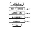
グラデーションマスク仕様生成処理の詳細を示すフローチャートであり、
輝度Bと最小透過率との関係を示すグラフであり、
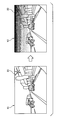
グラデーションマスクの重畳前後における表示用画像の変化を示す図である。
以下、本開示の一実施形態について説明する。本実施形態に係る車両用視界支援システムは、車両に搭載され、図1に示すように、車載カメラ1、ECU2(Electronic Control Unit、車両用視界支援装置の一例に相当する)、およびディスプレイユニット3を備えている。
車載カメラ1は、車両の後端付近に固定して搭載され、車両の周囲を、具体的には、車両の後方の所定範囲(例えば、通常のルームミラーでドライバーが見ることができる範囲)を繰り返し(例えば、1/30秒周期で)撮影し、撮影の結果得た当該所定範囲の撮影画像の映像信号をECU2に逐次出力する。
ECU2には、車載カメラ1から上記撮影画像が繰り返し入力されると共に、車両から車速の情報およびシフトレンジの情報が繰り返し入力されるようになっている。そしてECU2は、車載カメラ1から入力された撮影画像にグラデーションマスクを重畳し、重畳後の撮影画像の映像信号をディスプレイユニット3に入力する。ECU2は、例えば、CPU、RAM、ROM、I/Oを備えたマイクロコンピュータであってもよい。
ディスプレイユニット3は、ECU2から入力された映像信号の表す撮影画像を表示する装置であり、表示された撮影画像を車内のドライバーが見ることができるような位置(例えば、ルームミラーの位置、ダッシュボードの中央、ドアミラーの位置等)に配置される。
以下、このような構成の車両用視界支援システムの作動について説明する。ECU2は、電源が投入されて起動すると、図2に示す処理を実行するようになっている。
ここで、この出願に記載されるフローチャート、あるいは、フローチャートの処理は、複数のセクション(あるいはステップと言及される)から構成され、各セクションは、たとえば、S100と表現される。さらに、各セクションは、複数のサブセクションに分割されることができる、一方、複数のセクションが合わさって一つのセクションにすることも可能である。さらに、このように構成される各セクションは、デバイス、モジュール、ミーンズとして言及されることができる。
ECU2(言い替えれば、CPU)は、まずS110で、車載カメラ1を起動する。これにより、車載カメラ1が、車両の後方の所定範囲を繰り返し撮影し、撮影の結果得た当該所定範囲の撮影画像の映像信号をECU2に逐次出力するようになる。
続いてECU2は、S120~160の処理を繰り返し実行し始める。S120では、車両情報として、車速の情報およびシフト位置の情報を車両から取得する。
続いてS130では、車載カメラ1から、最新の撮影画像の映像信号を取得する。そして、この映像信号が表す撮影画像に対して各種補正を施し、補正後の撮影画像を表示用画像とする。
補正としては、撮影画像の上下左右の各端部を切り取って捨てるトリミング、歪みを補正する歪み補正等がある。補正後の表示用画像は、撮影画像に基づく表示用画像の一例に相当する。
続いてS140では、マスク画像(以下、グラデーションマスクという)の仕様を生成し、続くS150では、生成した仕様に従ったグラデーションマスクを作成し、作成したグラデーションマスクを、表示用画像中のマスク対象範囲に透過的に重畳する。
ここで、図3を参照してグラデーションマスクGMについて説明する。図3に例示するように、ECU2は、S150では、表示用画像10中の所定のマスク下端ラインMLからマスク上端ラインMUまでの全範囲をマスク領域とし、当該マスク領域と同じ形状のグラデーションマスクGMを作成し、作成したグラデーションマスクGMをマスク領域全体に透過的に重畳させる。
マスク上端ラインMUの位置は、表示用画像の上端と一致している。マスク下端ラインMLの位置は、グラデーションマスクの仕様の1つであり、S140で生成される。
なお、「透過的に重畳させる」とは、表示用画像中でグラデーションマスクGMに覆われる部分の画像(グラデーションマスクGM以外の画像)も、グラデーションマスクGMを透過して見えるように、重畳されることをいう。
このグラデーションマスクGMの透過率は、マスク下端ラインMLの位置では100%(すなわち、全透過)であり、マスク下端ラインMLからマスク上端ラインMUまで単調減少(例えば、マスク上端ラインからの距離の一次関数となるように減少)していき、マスク上端ラインMUの位置で最小透過率となる。最小透過率は、グラデーションマスクの仕様の1つであり、S140で生成される。
マスク下端ラインMLの位置で透過率100%(全透過)とするのは、マスク領域の端部からマスク領域に隣接する部分にかけて表示色を滑らかに変化させるためである。マスク下端ラインMLの位置で例えば透過率が80%となっていると、マスク領域とマスク領域に隣接する部分との間に線が見えてしまう。
グラデーションマスクGM自体は、黒色または灰色の単色で模様がない画像とする。色を黒または灰色(いわゆる無彩色)とするのは、赤や青等の有彩色を用いると、マスク領域において透過して表示される看板等の色が、本来の色と大きく異なってしまい、ドライバーに違和感を与えてしまう可能性があるからである。
続いてS160では、グラデーションマスクが透過的に重畳された当該表示用画像の映像信号をディスプレイユニット3に入力する。これにより、ディスプレイユニット3が当該表示用画像をドライバーに表示する。
ここで、S140におけるグラデーションマスクの仕様生成処理について詳細に説明する。グラデーションマスクの仕様生成処理においてECU2は、図4に示すように、まずS141で、直前のS120で取得した車速に基づいて、マスク下端ラインMLの位置を設定する。
まず、マスク下端ラインMLのデフォルト位置は、あらかじめ定められてECU2のROM等に記録されている。
このデフォルト位置は、例えば、自車両が水平な路面にいる場合に表示用画像に映る水平線に対して平行かつ当該水平線と同じ高さになるように設定されていてもよい。表示用画像中の水平線の位置は、車載カメラ1の仕様、車載カメラ1の車両への取り付け位置、車載カメラ1の車両への取り付け角度、および、撮影画像から表示用画像を作成するときの補正の内容が決まっていれば、ECU2の車両への取り付け時にあらかじめ特定することができる。
また、このデフォルト位置は、例えば、自車両が水平な路面にいる場合に表示用画像に映る水平線に対して平行かつ、当該水平線よりも高い位置になるように設定されていてもよい。
例えば、車載カメラ1から車両後方正面に100メートル離れた地点の地上6メートル(一般的な信号機の高さ)の目標位置が、表示用画像中のどの位置に相当するかは、車載カメラ1の仕様、車載カメラ1の車両への取り付け位置、車載カメラ1の車両への取り付け角度、および、撮影画像から表示用画像を作成するときの補正の内容が決まっていれば、ECU2の車両への取り付け時にあらかじめ特定することができる。そこで、この目標位置が映る表示用画像中の位置を、マスク下端ラインMLのデフォルト位置としてあらかじめ設定してもよい。
そして、マスク下端ラインMLの位置は、表示用画像中でデフォルト位置から上にオフセットされた位置とし、そのオフセット量は、車速が小さくなるほど大きくする。すなわち、車速が小さくなるほどマスク下端ラインMLの位置を高くする。
例えば、車速が時速50km以上である場合は、オフセット量をゼロとし、車速が時速50kmから0kmまでは、車速の一次関数で車速の減少と共にオフセット量を増加させ、車速が時速0kmの場合は、マスク下端ラインMLがマスク上端ラインMUと一致するようなオフセット量としてもよい。
このように車速が低いほどマスク領域を狭くするのは、車速が低いほど、後方をしっかり見る必要性が高くなるためである。また、車速が低いほど、車間距離が小さくなり、車間距離が小さくなるほど、表示用画像中で他車両(後続車両)の上端位置が高くなるからである。
続いてS143では、検出領域内の輝度を取得し、それら輝度の代表値Bを算出する。検出領域は、マスク領域中の一部の領域とする。例えば、図3に示すように、マスク領域中に3本の一画素幅の輝度検知ラインL1~L3を設定し、その輝度検知ラインL1~L3内の全領域を検出領域とする。輝度の代表値Bは、検出領域内の全画素の輝度分布に基づいた代表値であり、平均値を採用してもよいし、最頻値を採用してもよいし、中央値を採用してもよい。
続いてS145では、直前のS143で算出した輝度代表値Bに基づいて最小透過率(マスク上端ラインMUにおける透過率)を設定する。
具体的には、輝度代表値Bが小さいほど、最小透過率を小さくする(透過し難くする)。例えば、図5に示すように、輝度代表値Bの一次関数として最小透過率を設定してもよい。
このようにするのは、グラデーションマスクGMを重畳するのは、道路周辺の発光体(例えば建物に取り付けられた照明装置)によって自車両のドライバーが眩惑されてしまうことを防ぐためだからである。
つまり、道路周辺の発光体をドライバーが眩しいと感じるのは、夜間である等の理由で周囲が暗い場合である。昼間の明るい空の下では、道路周辺の発光体が明るく光っていたとしても、ドライバーがそれに眩惑される可能性は低い。
そこで本実施形態では、周囲が全体として暗い場合において特に眩惑を防ぐため、輝度代表値Bが小さい(輝度が全体として小さい)ほど、マスク上端ラインMUに設定される最小透過率を小さくする(透過し難くする)。
なお、最小透過率の変化に応じて、マスク上端ラインMUからマスク下端ラインMLまでの領域の透過率も(マスク下端ラインMLそのものを除いて)変化する。つまり、最小透過率が減少すれば、マスク領域のほぼ全体の透過率が減少し、最小透過率が増大すれば、マスク領域のほぼ全体の透過率が増大する。
もちろん、夜間に限らず昼間の周囲が明るい場合においてマスク上端ラインMUに設定される最小透過率を小さくすることも可能であるが、その場合は、グラデーションマスクGMによって表示用画像中の上部が暗くなってしまい、それを見たドライバーが、空が曇っているのか、雨が降っているのか等の誤った印象を受けてしまい、勘違いをしないまでも、ドライバーが違和感を覚えてしまう可能性がある。また、全体として輝度が高い昼間等は、全体が明るいので、グラデーションマスクGMで少し暗くするたけで、防眩の効果をある程度達成できる。逆に、全体として輝度が低い夜間等は、グラデーションマスクGMで輝度を大きく下げても違和感はさほどない。
ここで、検出領域をマスク領域内とするのは、グラデーションマスクGMを重畳する場所の輝度に応じてグラデーションマスクGMの透過率を設定することが望ましいからである。また、検出領域をマスク領域外の例えば路面の位置に設定すると、道路はヘッドライト等によって明るさが変動しやすいので、グラデーションマスクGMの透過率がめまぐるしく変化してしまい、その結果ドライバーに不快感を与えてしまう可能性がある。
続いてS147では、直前のS120で取得したシフト位置に基づいて、グラデーションマスクGMの透過率を決定する。この際、シフト位置がリバースであるか否かに応じて、透過率の決定方法が異なる。
シフト位置がリバースでない場合は、直前のS145で設定した最小透過率をマスク上端ラインMUの透過率とし、マスク下端ラインMLの透過率を100%とし、その間のマスク領域の透過率を、マスク下端ラインMLからマスク上端ラインMUまで単調減少(例えば、マスク下端ラインMLからの距離に対して線形的に減少)するよう、決定する。
シフト位置がリバースである場合は、S145の設定内容にかかわらず、グラデーションマスクGM全体の透過率を100%とする。すなわち、グラデーションマスクGMを重畳しないのと同じ効果がもたらされるよう、透過率を設定する。このようにするのは、車両が後退する場面では、後方が映った表示用画像の全体をグラデーションマスクGMの重畳なしで見せることで、カメラ映像を見易くするためである。
S147の後、図2のS150に進み、上記のように決定したグラデーションマスクGMの仕様(透過率および形状)に従って、グラデーションマスクGMを作成し、作成したグラデーションマスクGMを表示用画像のマスク領域に重畳する。
その際、シフト位置がリバースでない場合は、S147で決定した通り、マスク領域のマスク上端ラインMUにおいて透過率が上記の最小透過率(例えば70%)となり、マスク上端ラインからマスク下端ラインまで透過率が大きくなり、マスク下端ラインMLで透過率が100%となるよう、周知のアルファブレンド処理で重畳を行う。そして、S160では、この重畳後の表示用画像をディスプレイユニット3に表示させる。
図6に、グラデーションマスクGMが重畳される前の表示用画像10(左側の画像)と、グラデーションマスクGMが重畳された後の表示用画像10(右側の画像)を比較表示する。
この図に例示するように、グラデーションマスクGMが重畳された表示用画像では、右上のライト20の輝度が弱まるので、ドライバーがライト20によって眩惑される可能性が低下する。
以上説明した通り、ECU2は、撮影画像中の所定の検出領域内の輝度の代表値が小さいほど小さい透過率を設定する。これにより、周囲が全体として暗く、道路周辺の発光体によって自車両のドライバーが眩惑されてしまう可能性が高い場合に、グラデーションマスクGMの透過率が小さくなって発光体の輝度が抑えられるので、自車両のドライバーが眩惑されてしまう可能性が低減される。
なお、上記実施形態において、ECU2が、S130を実行することで取得セクションの一例として機能し、S141を実行することで下端設定セクションの一例として機能し、S145、147を実行することで透過率設定セクションの一例として機能し、S150を実行することで重畳セクションの一例として機能し、S160を実行することで表示制御セクションの一例として機能する。
(他の実施形態)
以上、本開示の実施形態について説明したが、本開示の範囲は、上記実施形態のみに限定されるものではなく、本開示の各機能を実現し得る種々の形態を包含するものである。例えば、以下のような形態も許容される。
以上、本開示の実施形態について説明したが、本開示の範囲は、上記実施形態のみに限定されるものではなく、本開示の各機能を実現し得る種々の形態を包含するものである。例えば、以下のような形態も許容される。
(1)上記実施形態では、グラデーションマスクGMは、マスク下端ラインMLにおいて透過率が100%(全透過)となっている。しかし、マスク領域とマスク領域に隣接する部分との間に線が見えてしまうことが許される場合は、マスク下端ラインMLの位置でグラデーションマスクGMの透過率が100%以外(例えば80%)となっていてもよい。
(2)また、上記実施形態では、検出領域は、マスク領域中の輝度検知ラインL1~L3であったが、検出領域は、マスク領域中のランダムに選んだ画素群であってもよいし、マスク領域全体でもよい。
あるいは、グラデーションマスクGMの透過率がめまぐるしく変化することが許される場合、検出領域はマスク領域内の一部とマスク領域外の一部を含む領域であってもよいし、マスク領域外の一部のみを含む領域であってもよい。
(3)また、上記実施形態では、グラデーションマスクGMの色を黒または灰色の無彩色としている。しかし、表示用画像中の看板等の色が、本来の色と大きく異なってしまうことが許される場合は、グラデーションマスクGMの色を有彩色としてもよい。
(4)上記実施形態では、車載カメラ1から取得した撮影画像に対して補正を行った結果の画像を表示用画像として用いているが、車載カメラ1から取得した撮影画像をそのまま表示用画像としてもよい。
(5)また、上記実施形態では、表示用画像のマスク領域に重畳するマスクとして、透過率が一様でないグラデーションマスクGMを例示しているが、透過率が一様のマスクを重畳するようになっていてもよい。
このようになっていても、検出領域L1~L3内の輝度代表値が小さいほど当該一様の透過率を小さくするようになっていれば、道路周辺の発光体の光によって自車両のドライバーが眩惑されてしまう可能性を低減するという本開示の目的は達成される。
(6)また、上記実施形態では、車載カメラ1は、車両の後方の所定範囲を撮影するようになっているが、車載カメラ1の撮影範囲は、車両の後方に限らず、車両の前方でも側方でもよい。
本開示は、実施例に準拠して記述されたが、本開示は当該実施例や構造に限定されるものではないと理解される。本開示は、様々な変形例や均等範囲内の変形をも包含する。加えて、様々な組み合わせや形態、さらには、それらに一要素のみ、それ以上、あるいはそれ以下、を含む他の組み合わせや形態をも、本開示の範疇や思想範囲に入るものである。
本開示は、実施例に準拠して記述されたが、本開示は当該実施例や構造に限定されるものではないと理解される。本開示は、様々な変形例や均等範囲内の変形をも包含する。加えて、様々な組み合わせや形態、さらには、それらに一要素のみ、それ以上、あるいはそれ以下、を含む他の組み合わせや形態をも、本開示の範疇や思想範囲に入るものである。
Claims (5)
- 車両の周囲を撮影する車載カメラ(1)から撮影画像を取得する取得セクション(S130)と、
前記撮影画像中の所定の検出領域(L1~L3)内の輝度の代表値が小さいほど小さい透過率を設定する透過率設定セクション(S145、S147)と、
取得した撮影画像に基づく表示用画像(10)中のマスク領域に、前記透過率のマスク(GM)を重畳する重畳セクション(S150)と、
前記マスクが透過的に重畳された前記表示用画像をディスプレイユニット(3)に表示させる表示制御セクション(S160)と、を備えた車両用視界支援装置(2)。 - 前記透過率設定セクションは、前記代表値に基づいて最小透過率を設定し、
前記マスク領域は、前記表示用画像中の所定のマスク下端ライン(ML)よりも上方の領域であり、
前記重畳セクションは、前記マスク領域のマスク上端ライン(MU)において透過率が前記最小透過率となり、前記マスク上端ラインから前記マスク下端ラインまで透過率が大きくなるように作成した前記マスクを、前記表示用画像中の前記マスク領域に重畳することを特徴とする請求項1に記載の車両用視界支援装置。 - 前記マスク下端ラインは、前記車両が水平な路面にいる場合の水平線に対して平行かつ前記水平線と同じ高さ又はより上方に位置するように設定されていることを特徴とする請求項1または2に記載の車両用視界支援装置。
- 前記マスク領域は、前記表示用画像中の所定のマスク下端ライン(ML)よりも上方の領域であり、
前記車両の車速が小さいほど前記マスク下端ラインを高く設定する下端設定セクション(141)を備えたことを特徴とする請求項1ないし3のいずれか1つに記載の車両用視界支援装置。 - 前記検出領域は、前記マスク領域に含まれることを特徴とする請求項1ないし4のいずれか1つに記載の車両用視界支援装置。
Applications Claiming Priority (2)
| Application Number | Priority Date | Filing Date | Title |
|---|---|---|---|
| JP2012156640A JP2014021543A (ja) | 2012-07-12 | 2012-07-12 | 車両用視界支援装置および車両用視界支援プログラム |
| JP2012-156640 | 2012-07-12 |
Publications (1)
| Publication Number | Publication Date |
|---|---|
| WO2014010179A1 true WO2014010179A1 (ja) | 2014-01-16 |
Family
ID=49915664
Family Applications (1)
| Application Number | Title | Priority Date | Filing Date |
|---|---|---|---|
| PCT/JP2013/003851 Ceased WO2014010179A1 (ja) | 2012-07-12 | 2013-06-20 | 車両用視界支援装置 |
Country Status (2)
| Country | Link |
|---|---|
| JP (1) | JP2014021543A (ja) |
| WO (1) | WO2014010179A1 (ja) |
Cited By (1)
| Publication number | Priority date | Publication date | Assignee | Title |
|---|---|---|---|---|
| GB2527091A (en) * | 2014-06-11 | 2015-12-16 | Nissan Motor Mfg Uk Ltd | Anti-glare mirror |
Families Citing this family (2)
| Publication number | Priority date | Publication date | Assignee | Title |
|---|---|---|---|---|
| JP2017028349A (ja) * | 2015-07-15 | 2017-02-02 | 株式会社デンソー | 映像処理装置、運転支援表示システム、及び映像処理方法 |
| DE102017116849A1 (de) * | 2017-07-25 | 2019-01-31 | Mekra Lang Gmbh & Co. Kg | Indirektes Sichtsystem für ein Fahrzeug |
Citations (4)
| Publication number | Priority date | Publication date | Assignee | Title |
|---|---|---|---|---|
| JPH06105194A (ja) * | 1992-09-16 | 1994-04-15 | Murakami Kaimeidou:Kk | 車載カメラ用オプトエレクトロニックフィルタ |
| JPH09214827A (ja) * | 1996-02-02 | 1997-08-15 | Mitsubishi Electric Corp | 車載カメラ装置 |
| WO2006114962A1 (ja) * | 2005-04-20 | 2006-11-02 | Autonetworks Technologies, Ltd. | 車載カメラシステム |
| JP2010058631A (ja) * | 2008-09-03 | 2010-03-18 | Mazda Motor Corp | 車両用情報表示装置 |
-
2012
- 2012-07-12 JP JP2012156640A patent/JP2014021543A/ja active Pending
-
2013
- 2013-06-20 WO PCT/JP2013/003851 patent/WO2014010179A1/ja not_active Ceased
Patent Citations (4)
| Publication number | Priority date | Publication date | Assignee | Title |
|---|---|---|---|---|
| JPH06105194A (ja) * | 1992-09-16 | 1994-04-15 | Murakami Kaimeidou:Kk | 車載カメラ用オプトエレクトロニックフィルタ |
| JPH09214827A (ja) * | 1996-02-02 | 1997-08-15 | Mitsubishi Electric Corp | 車載カメラ装置 |
| WO2006114962A1 (ja) * | 2005-04-20 | 2006-11-02 | Autonetworks Technologies, Ltd. | 車載カメラシステム |
| JP2010058631A (ja) * | 2008-09-03 | 2010-03-18 | Mazda Motor Corp | 車両用情報表示装置 |
Cited By (1)
| Publication number | Priority date | Publication date | Assignee | Title |
|---|---|---|---|---|
| GB2527091A (en) * | 2014-06-11 | 2015-12-16 | Nissan Motor Mfg Uk Ltd | Anti-glare mirror |
Also Published As
| Publication number | Publication date |
|---|---|
| JP2014021543A (ja) | 2014-02-03 |
Similar Documents
| Publication | Publication Date | Title |
|---|---|---|
| JP5251947B2 (ja) | 車両用画像表示装置 | |
| US8514282B2 (en) | Vehicle periphery display device and method for vehicle periphery image | |
| EP2794353B1 (en) | Vehicle rear monitoring system | |
| JP4254887B2 (ja) | 車両用画像表示システム | |
| EP2476587B1 (en) | Vehicle surrounding monitor apparatus | |
| JP5783279B2 (ja) | 画像処理装置 | |
| CN110877572A (zh) | 周边监视装置 | |
| US20170282813A1 (en) | Image display control device and image display system | |
| US20160059700A1 (en) | Vehicle control apparatus | |
| JP2009017020A (ja) | 画像処理装置及び表示画像生成方法 | |
| EP2476588A1 (en) | Vehicle surrounding monitor apparatus | |
| JP5966513B2 (ja) | 車両の後側方撮影装置 | |
| JP5464741B2 (ja) | 画像合成装置、及び、画像合成方法 | |
| CN109074685B (zh) | 用于调整图像的方法、设备、系统和计算机可读存储介质 | |
| CN108463998A (zh) | 驾驶辅助装置以及驾驶辅助方法 | |
| JP2005223605A (ja) | 画像処理方法、画像処理システムおよび画像処理装置 | |
| JP2008285105A (ja) | 情報表示装置 | |
| JP6424449B2 (ja) | 後方状況表示装置、後方状況表示方法 | |
| CN111216635B (zh) | 车载装置 | |
| JP3961969B2 (ja) | 車両周辺画像処理システム | |
| WO2014010179A1 (ja) | 車両用視界支援装置 | |
| JP2011008459A (ja) | 車載カメラ装置 | |
| CN109987027A (zh) | 一种半挂车环视盲区显示规划的设计方法 | |
| JP6168024B2 (ja) | 撮影画像表示装置、撮影画像表示方法および撮影画像表示プログラム | |
| JP2018113622A (ja) | 画像処理装置、画像処理システム、及び、画像処理方法 |
Legal Events
| Date | Code | Title | Description |
|---|---|---|---|
| 121 | Ep: the epo has been informed by wipo that ep was designated in this application |
Ref document number: 13816992 Country of ref document: EP Kind code of ref document: A1 |
|
| NENP | Non-entry into the national phase |
Ref country code: DE |
|
| 122 | Ep: pct application non-entry in european phase |
Ref document number: 13816992 Country of ref document: EP Kind code of ref document: A1 |